


High Resolution Series |
Subwoofer |
HRS-8, HRS-10, and HRS-12 |
User's Manual |
Important Safety
Instructions
1.Read Instructions
2.Keep these Instructions
3.Heed all Warnings.
4.Follow all Instructions
5.Do not use this apparatus near water.
6.Clean only with dry cloth.
7.Do not install near any heat sources such as radiators, heat registers, stoves, or other apparatus (including amplifiers) that produce heat.
8.Unplug this apparatus during lightning storms or when unused for long periods of time.
9.Refer all servicing to qualified service personnel. Servicing is required when the apparatus has been damaged in any way, such as a power-supply cord or plug is damaged, liquid has been spilled or objects have fallen into the apparatus, the apparatus has been exposed to rain or moisture, does not operate normally, or has been dropped.
10.Ventilation — The apparatus should be situated so that its location or position does not interfere with its proper ventilation. For example, the apparatus should not be situated on a bed, sofa, rug, or similar surface that may block any ventilation openings; or placed in a built-in installation such as
a bookcase, cabinet, or closed equipment rack that may impede the flow of air through ventilation openings.
11.Power Sources — The apparatus should be connected to a power supply only of the type described in these operation instructions or as marked on the apparatus.
12.Power Cord Protection — Power-supply cords should be routed so that they are not likely to be walked upon or pinched by items placed upon or against them, paying particular attention to cords at plugs, convenience
receptacles, and the point where they exit the apparatus.
13.Non-use Periods—The power cord of the apparatus should be unplugged from the outlet when unused for a long period of time.
14.Object and Liquid Entry — Care should be taken so that objects do not fall into and liquids are not spilled into the inside of the apparatus.
15.Servicing — The user should not attempt to service the apparatus beyond those means described in this operating manual. All other servicing should be referred to qualified service personnel.
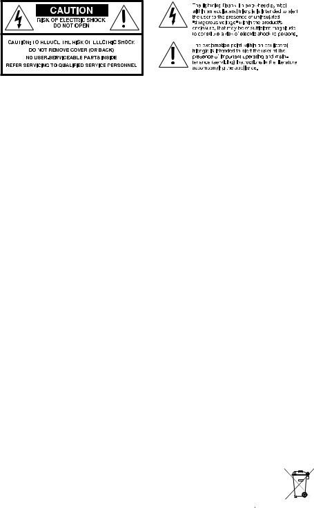
16.To Prevent Electric Shock, do not use this polarized plug with an extension cord, receptacle or other outlet unless the blades can be fully inserted to prevent blade exposure.
Pour préevenir les chocs électriques ne pas utiliser cette fiche polariseé avec un prolongateur, un prise de courant ou une autre sortie de courant, sauf si les lames peuvent être insérées à fond sans laisser aucune pariie à découvert.
17.Grounding or Polarization — Precautions should be taken so that the grounding or polarization means of the Component is not defeated.
This apparatus does not exceed the Class
A/Class B (whichever is applicable) limits for radio noise emissions from digital apparatus as set out in the radio interference regulations of the Canadian Department of Communications.
ATTENTION — Le présent appareil numérique n'émet pas de bruits radioélectriques dépassant las limites applicables aux appareils numériques de class A/de class B
(selon le cas) prescrites dans le règlement sur le brouillage radioélectrique
édicté par les ministere des communications du Canada.


 User's Manual

18. This equipment has been tested and found to comply with the limits for a Class
B digital device, pursuant to Part15 of the
FCC Rules. These limits are designed to provide reasonable protection against
harmful interference in a residential installation. This equipment generates, uses and can radiate radio frequency energy and, if not installed and used in accordance with the instructions, may cause harmful interference to radio communications. However, there is no guarantee that interference will not occur in a particular installation.
If this equipment does cause harmful interference to radio or television reception, which can be determined by turning the
equipment off and on, the user is encouraged to try to correct the interference by one or more of the following measures:
Reorient or relocate the receiving antenna.
Increase the separation between the equipment and receiver.
Connect the equipment into an outlet on a circuit different from that to which the receiver is connected.
Consult the dealer or an experienced radio/TV technician for help.
19. Caution: Changes or modifications not expressly approved by Sunfire could void the user's authority to operate this equipment.
WARNING:THIS SUBWOOFER IS CAPABLE OF PRODUCING |
|
VERY HIGH SOUND PRESSURE LEVELS. YOU MUST TAKE |
|
EVERY PRECAUTION TO PROTECT YOUR HEARING FROM |
|
PERMANENT DAMAGE. |
|
Contents |
|
Safety Instructions......................................... |
2 |
Introduction.................................................... |
4 |
Features......................................................... |
4 |
Overview........................................................ |
5 |
Control Panel Features.................................. |
6 |
Installation...................................................... |
8 |
Connections................................................... |
9 |
Location....................................................... |
10 |
System Configurations................................. |
11 |
Adjusting the Controls.................................. |
15 |
Specifications............................................... |
16 |
Troubleshooting Guide................................. |
17 |
Limited Warranty.......................................... |
19 |
Service Assistance....................................... |
19 |
To find out more about this and other Sunfire products, please visit our website: www.sunfire.com

 User's Manual
Introduction
Thank you for purchasing a Sunfire
High Resolution Series Subwoofer. We hope you enjoy it and the music it makes as much as we have enjoyed creating it for you.
The big breakthrough features of the subwoofer are its uncanny 1,000W Tracking Downconverter amplifier, and its long throw, High Back-emf woofer. These powerful forces combine to produce as much bass as several 15 inch drivers mounted in a cabinet the size of a small refrigerator! And, the High Resolution Series' extended frequency response means that your subwoofer is the perfect match to virtually any loudspeaker.
Unpacking
Your Sunfire subwoofer should reach you in perfect condition. If you do notice any shipping damage, please contact your Sunfire Dealer immediately.
Gently lift out the unit and remove all the packing material. It is important to save all the packing materials and the box in case your subwoofer ever needs to be moved or shipped for repair.
Make sure that you keep your sales receipt. It is the only way to establish the duration of your Limited Warranty and it may come in useful for insurance purposes.
Please take a moment to fill out and mail the Sunfire Customer Response card. Also read the serial number located on the control panel and record it here:
Features
•Patented high-pressure, High Backemf, extra-long-throw design
•High efficiency Tracking Downconverter amplifier
•Low distortion
•Premium quality driver
•Extremely compact size
•Automatic signal-sensing turn-on and standby mode
•Line-level inputs
•Speaker-level binding post inputs
•Line-level high-pass outputs
•Phase control
•Crossover frequency control
•Volume control
•Soft clipping circuit allows graceful overload and prevents speaker damage due to clipping
Care
To maintain the speaker cabinet’s finish, first unplug the power cord and then use a soft cloth to clean the surfaces.
If your Sunfire subwoofer needs servicing, please read the troubleshooting section on page 21. If a problem persists, contact your nearest authorized Sunfire
Dealer.
Serial Number:
Purchased from:
Date:

 User's Manual

Overview
The Sunfire HRS subwoofers are designed to give you the best possible low-frequency sound quality for your
Home Theater and music playback experience. They incorporate a tremendously powerful built-in amplifier to produce tight, seismic, denture-rumbling bass that you can feel as well as hear.
There are three models in the high resolution series: the HRS-8, HRS-10, and the HRS-12. (The number represents the driver diameter in inches.) The control panel, connections and operation are the same for each subwoofer model, and this manual covers all three models.
Each subwoofer has controls for adjusting the crossover frequency, phase, and volume. They also have line-level and speaker-level inputs for easy incorporation into existing systems, or as part of a subwoofer/satellite speaker combination.
The Driver
To have lots of bass requires the movement of lots of air. To achieve this, the subwoofer's driver has been designed to travel back and forth approximately five times further than a normal driver. This gives lots of air movement and massive bass performance.
The Tracking Downconverter
Amplifier
The large movement range of the driver generates greater air pressure inside the box than a conventional driver. In order to create this range of movement, we designed a drive amplifier that is much more powerful than an ordinary amplifier.
A signal compressor circuit kicks in automatically if the input signal level reaches a level that would overload the driver. This maintains a ceiling on the output without clipping.
If the input signal is driven even further, a ‘soft clipping’ circuit is enabled. This allows the driver to put more sound into the room to satiate the power hungry user, but without distortion or damage to the driver. This produces extremely high sound pressure levels (SPL) in your room without the driver banging against its mechanical stops.
Sub/LFE
In this manual, the term “Sub/LFE” is used to denote the subwoofer or Low Frequency Effects output, commonly found on Home Theater processors and receivers.

 User's Manual
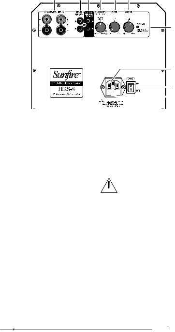
Control Panel Features
5 |
6 7 |
8 |
9 |
10 |
1
3
2


 4
4
1. Power Indicator
This light is bright when the subwoofer is on, and dim when the subwoofer is in standby mode.
2. Power Switch
Press the top of this rocker switch to turn on the subwoofer.
The subwoofer has an automatic signal-detection circuit. After approximately fifteen minutes with no signal, the subwoofer will go into its quiet standby mode. The presence of an audio signal will turn it back on.
4. AC Line Fuse
The subwoofer is supplied with a conservative slow-blow type fuse to protect the electronics. If this fuse fails, replace it with the exact same type and current rating for your local AC voltage, as marked on the control panel near the fuse holder.
Note: Always unplug the power cord from your AC outlet before
 removing the fuse. To replace or inspect the fuse, use a small flatended screwdriver to gently pry out the
fuse carrier and fuse.
Normally you can leave the switch on, and let the subwoofer turn on when a signal is present, or off when it's not.
At night, or if you go out, or on vacation, you can press the bottom of the power switch to turn the subwoofer off.
3. IEC Power Connector
The subwoofer comes with a detachable linecord that attaches here. Make sure it is firmly pushed into place.
Connect the other end to an AC outlet that is properly configured for the type of plug and has the correct voltage for your model.
5. Speaker-Level Inputs
If you are using a receiver which only has speaker-level outputs, you can connect it using the speaker-level inputs (see the hookup diagram on page 14). They can accept bare wire, banana, or dual-banana connectors.
If you experience excessive noise or hum using the line-level inputs, try using the speaker-level inputs. This may lower the background noise level.

 User's Manual
 Loading...