


Operating Instructions • Warning Information • Parts Breakdown
SPECIFICATIONS
Fluid Orifice................................................................................... |
1.3mm |
|
Air Inlet: .......................................................................................... |
1/4" NPT |
|
Rec. Max. Inlet Pressure....................................................................... |
60 |
PSI |
CFM:........................................................................................... |
7.2 at 50 |
PSI |
Nozzle Pressure.................................................................................... |
47 |
PSI |
Cup Size.............................................................................................. |
1000cc |
|
Some dust created by power sanding, sawing, grinding, drilling, and other construction activities contains chemicals known to cause cancer, birth defects or other reproductive harm. Some examples of these chemicals are:
•lead from lead-based paints,
•crystalline silica from bricks and cement and other masonry products, and
•arsenic and chromium from chemically-treated lumber.
Your risk from these exposures varies, depending on how often you do this type of work. To reduce your exposure to these chemicals: work in a well ventilated area, and work with approved safety equipment,
such as those dust masks that are specially designed to filter out microscopic particles.
Always read instructions before using power tools
Always wear safety goggles
Wear hearing protection
Avoid prolonged exposure to vibration
SX70C
Spray Gun
and Cup
SX70C: Parts Breakdown & Operating Manual |
|
rev. 04/28/06 |
 - FOLLOW THESE RULES FOR SAFE OPERATION!
•During cleaning and flushing, solvents can be forcefully expelled from fluid and air passages. Some solvents can cause eye injury.
•Be sure all in the area are wearing impact-resistant eye and face protection.
•Even small projectiles can injure eyes and cause blindness.
•Air under pressure can cause severe injury. Always shut off air supply, drain hose of air pressure and disconnect tool from air supply when not in use, before changing accessories or when making repairs. Never direct air at yourself or anyone else. Whipping hoses can cause serious injury. Always check for damaged or loose hoses and fittings. Never use quick change couplings at tool. They add weight and could fail due to vibration. Instead, add a hose whip and connect coupling between air supply and hose whip, or between hose whip and leader hose. Do not exceed maxmum air inlet pressure of 60 PSI.
•Always use tool a safe distance from other people in work area.
•Maintain tools with care. Keep tools clean and oiled for best and safest performance. Follow instructions for lubricating and changing accessories. Wiping or cleaning rags and other flammable waste materials must be placed in a tightly closed metal container and disposed of later in the proper fashion.
•Do not wear loose or ill-fitting clothing; remove watches and rings.
•Do not over reach. Keep proper footing and balance at all times. Slipping, tripping and falling can be a major cause of serious injury or death. Be aware of excess hose left on the walking or work surface.
•Do not force tool. It will do the job better and safer at the rate for which it was designed.
•Do not abuse hoses or connectors. Never carry tool by the hose or yank hose to disconnect from air supply. Keep hoses from heat, oil and sharp edges. Check hoses for weak or worn condition before each use, making certain that all connections are secure.
•High sound levels can cause permanent hearing loss. Protect yourself from noise.
Noise levels vary with work surface. Wear ear protection.
•When possible, secure work with clamps or vise so both hands are free to operate tool.
•Repetitive work motions, awkward positions and exposure to vibration can be harmful to hands and arms.
•Avoid inhaling dust or handling debris from work processes which can be harmful to your health.
•Operators and maintenance personnel must be physcally able to handle the bulk, weight and power of this tool.
•This tool is not intended for using in explosive atmospheres and is not insulated for contact with electric power sources.
•Solvent and coatings can be highly flammable or combustible especially when sprayed. Adequate exhaust must be provided to keep air free of accumulations of flammable vapors.
• Smoking must never be allowed in the spray area.
•Fire extinguishing equipment must be present in the spray area.
•Never spray near sources of ignition such as pilot lights, welders, etc.
•Halogenated hydrocarbon solvents — for example, methylene chloride — are not chemcally compatible with the aluminum that might be used in many system components. The chemical reaction caused by these solvents reacting with aluminum can become violent and lead to an equipment explosion. Guns with stainless steel fluid passages may be used with these solvents. However, aluminum is widely used in other spray application equipment - such as material pumps, cups and reglators, valves, etc. Check all other equipment items before use and make sure they can also be used safely with these solvents. Read the label or data sheet for the material you intend to spray. If in doubt as to whether or not a coating or cleaning material is compatble, contact your material supplier.
•Sprayed materials may be harmful if inhaled, or if there is contact with the skin. Adequate exhaust must be provided to keep the air free of accumulations of toxic materials. Use a mask or respirator whenever there is a chance of inhaling sprayed materials. The mask must be compatble with the material being sprayed and its concentration.
SX70C: Parts Breakdown & Operating Manual |
2 |
rev. 04/28/06 |

Air supply
Air |
Length of Pipe (ft.) |
||||
Flow |
|||||
|
|
|
|
||
CFM |
|
|
|
|
|
50 |
100 |
150 |
200 |
||
10 |
1/2" |
3/4" |
3/4" |
|
|
|
|
|
|
|
|
20 |
3/4" |
3/4" |
3/4" |
3/4" |
|
|
|
|
|
|
|
30 |
3/4" |
3/4" |
1" |
1" |
|
|
|
|
|
|
|
40 |
1" |
1" |
1" |
1" |
|
|
|
|
|
|
|
50 |
1" |
1" |
1" |
1" |
|
|
|
|
|
|
|
70 |
1" |
1" |
1-1/4" |
1-1/4" |
|
|
|
|
|
|
|
Pitch pipe back toward air receiver
|
Compressor Unit |
Install drain at |
|
|
|
|
|
|
|
each low point |
|
|
|
|
Oil & Water |
|
|
|
Extractor |
Drain |
|
25 Feet |
Drain |
|
|
||
|
|
or More |
|
|
|
Oil and Water Extractor should be at least 25 ft. |
|
|
|
from the compressor, farther if possible. |
|
Never mount oil and water extractor on or near the air compressor.
During compression, air temperature is greatly increased. As the air cools down to room temperture, moisture condenses in the air line, on its way to the spray gun. Therefore, always mount the oil and water extractor at a point in the air supply system where the compressed air temperature is lowest.
Drain air lines properly.
Pitch all air lines back towards the compressor so that condensed moisture will flow back into the air receiver where it can be drained off. Each low point in an air line acts as a water trap. Such points should be fitted with an easily accessible drain. See diagram above.
TYPES OF INSTALLATION
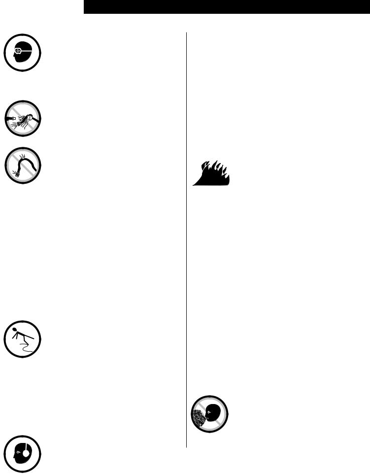
This spray gun is rugged in construction, and is built to yield exceptional value. The life of this product and the efficiency of its operation depend upon a knowledge of its construction, use and maintenance.
|
Fluid Control Screw |
|
|
Air Inlet |
Oil and |
|
Water |
|
|
|
|
|
Atomization |
Extractor |
Fluid |
Pressure |
|
Gauge |
|
|
Siphon Cup |
|
|
|
|
|
|
Air Hose |
|
SIPHON FEED CUP HOOKUP
Air pressure for atomization is reglated at extractor. Amount of fluid is adjusted by fluid control screw on gun, viscosity of paint, and air pressure.
|
Fluid Control Screw |
|
|
|
Air Inlet |
|
Oil and |
|
|
Atomization |
Water |
|
|
Extractor |
|
|
Cup |
Pressure |
|
Fluid |
|
||
Regulator |
Gauge |
|
|
Siphon Cup |
|
||
|
|
|
|
PRESSURE FEED CUP HOOKUP
For |
fine |
finishing |
with |
limited |
spraying. |
Air |
pressure |
for atomization |
is reglated at |
||
extractor; fluid pressure at cup regulator. For heavy fluids and internal mix nozzle spraying, fluid adjusted by control screw on gun.
Air Hose
SX70C: Parts Breakdown & Operating Manual |
|
rev. 04/28/06 |
FOR BEST PERFORMANCE,
PLEASE BE SURE TO DO THE FOLLOWING
BEFORE USING THIS TOOL
•Tighten the gun to the cup securely with the nut and fitting supplied.
•Be sure to have the proper air pressure at the gun to operate. Proper air pressure for this tool should not exceed 50 PSI.
•Adjust fluid control screw and spray width adjustment screw to your desired pattern before using on production.
•Clean all parts after use.
Adjustments
|
Trigger pivot |
||
|
|
|
Spray width |
|
|
|
|
|
|
|
adjustment screw |
Fluid |
|
|
Turn right for round, |
|
|
left for fan. |
|
pack |
|
|
|
|
|
|
|
|
|
|
Fluid Control Screw |
|
|
|
Turn right to decrease |
|
|
|
flow, left to increase. |
|
|
Air |
|
|
|
Valve |
|
spraying
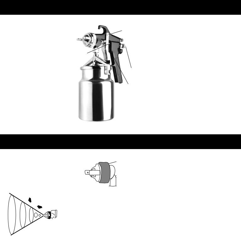
In normal use, the nozzle wings are horzontal as shown here. This provides a vertical fan-shaped pattern which gives maxmum, even material coverage as the gun is moved back and forth parallel to the surface being finished.
Set inlet pressure at no more than 60 PSI. For optimum performance, some materials may spray better at PSI ratings below 60 PSI. If unsure, always test at PSI ratings before using on final production. Try spray. If it is too fine, decrease the air pressure or open fluid control screw. If the spray is too thick, close the fluid control screw. Reglate the pattern width and repeat adjustment of spray as needed.
Spray pattern may be infinitely adjusted from round to flat.
SX70C: Parts Breakdown & Operating Manual |
4 |
rev. 04/28/06 |

Operation
Proper handling of the gun is essential for obtaining a good finish. The gun should be held at a right angle to the surface being covered, and moved parallel with it. For precise control of the gun and material, the trigger should be released before the end of the stroke.
Hold the gun from 6 to 12 inches away from the surface depending
Even and wet coat
6 to 12 inches
Start |
Pull |
Release |
End of |
stroke |
trigger |
trigger |
Stroke |
RIGHT
on material and atomizing pressure. For a uniform finish, lap each stroke over the preceding stroke, making sure the spray is smooth and wet.
Using the lowest |
possible atomizing air pressure will reduce |
||
overspray and provide maxmum efficiency. |
|||
|
|
|
|
|
|
|
|
|
Light Coat |
Heavy Coat |
|
WRONG
Cleaning and Maintenance
SPRAY GUN
1.Submerge the front end of the gun in solvent just until the fluid connection is covered.
2.Paint that has built up on the gun should be removed using a bristle brush and solvent.
3.Never submerge all of the spray gun in solvent because:
•This will dissolve the lubricant in the leather packings and on wear surfaces, causing them to dry out and resulting in difficult operation and faster wear.
•Air passages in the gun will become clogged with dirty solvent.
4.Using a rag moistened with solvent, wipe down the outside of the gun.
5.Oil gun daily. Use a drop of lightweight machine oil on:
A.fluid needle packing
B.air valve packing
C.trigger pivot point
See Fig. 1 for Location of Above Points.
6.NOTE: Do not soak rubber o-rings or seals in paint thinner. O-rings and seals can be wiped clean with paint thinner but soaking can cause these items to
deteriorate over time.
7.Caution: Do not use lubricants which contain silcone. Silcone may cause defects in the finish application.
CAUTION
To avoid cross-threading, all spray gun parts should be screwed in hand tight initially. If the parts can not easily be turned by hand, be sure you have the correct parts, unscrew, realign, and try again. NEVER use excessive force in matching parts.
AIR NOZZLE, FLUID NOZZLE, AIR VALVE ASSEMBLY
1.All nozzles and needles are made to exact standards. They should be handled carefully.
2.To clean nozzles, immerse them in solvent until any dried material is dissolved, then blow them clean.
3.Do not use metal or sharp instrument to probe any of the holes in the nozzles.
4.Air flow should occur before fluid flow when the gun is triggered. It may be necessary to adjust the fluid control screw to make sure air flows before fluid.
5.Do not alter the gun in any way.
SIPHON CUP
Turn off air supply. Disconnect cup from lid. Raise tube out of material and pull trigger to allow remaining material to drain back to the cup. Empty the cup of material. Clean the cup, lid and tube. Add some thinner
to cup. Reassemble. Turn on air supply and spray with
proper cleaning solvent. Repeat with clean solvent
if necessary. Remove solvent, disconnect gun, remove air cap and clean. Wipe gun and cup with rag dampened
with solvent.
C
A
B
Fig. 1
SX70C: Parts Breakdown & Operating Manual |
5 |
rev. 04/28/06 |
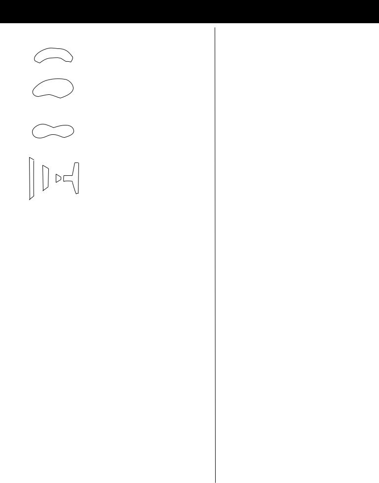
Troubleshooting
|
SPRAY PATTERN/ |
PROBLEM |
|
SOLUTION |
|||
|
Condition |
One side of nozzle wing is |
|
Soak nozzle in solvent to loosen clog, then blow air through |
|||
|
|
|
until clean. To clean orifices use a broom straw or toothpick. |
||||
|
|
clogged. |
|
||||
|
|
|
Never try and detach dried material with sharp tool. |
||||
|
|
|
|
|
|||
|
|
|
|
|
|
|
|
|
|
A.) |
Loose air nozzle. |
|
A.) |
Tighten air nozzle. |
|
|
|
B.) |
Material around outside of |
|
B.) |
Take off air nozzle and wipe off fluid tip, |
|
|
|
|
air nozzle has dried. |
|
|
using rag moistened with thinner. |
|
|
|
|
|
|
|
|
|
|
|
A.) |
Atomization air pressure is set |
A.) |
Reduce air pressure. |
||
|
|
|
too high. |
|
B.) |
Increase material control by turning fluid |
|
|
|
|
|
|
|||
|
|
B.) |
Trying to spray a thin material |
|
control screw to left, while reducing spray |
||
|
|
|
in too wide a pattern. |
|
|
width by turning spray width adjustment |
|
|
|
|
|
|
|
screw to right. |
|
|
|
|
|
|
|
|
|
|
|
A.) |
Packing around needle valve |
|
A.) |
Back up knurled nut, put a few drops of |
|
|
|
|
is dried out. |
|
|
machine oil on packing, re-tighten nut. |
|
|
|
B. |
Fluid nozzle loosely installed, |
B.) |
Take off fluid nozzle, clean rear of nozzle and |
||
|
|
|
or dirt between nozzle |
|
|
seat in gun body. Replace nozzle and bring in |
|
|
|
|
and body. |
|
|
tight to body. |
|
|
|
C.) |
Loose or defective swivel nut |
C.) |
Tighten or change out swivel nut. |
||
|
Spitting |
|
on siphon cup. |
|
|
|
|
|
|
|
|
|
|
|
|
|
Improper spray pattern. |
A.) |
Gun improperly adjusted. |
|
A.) |
Readjust gun. Follow instructions carefully. |
|
|
B.) |
Dirty air cap. |
|
B.) |
Clean air cap. |
||
|
|
|
|||||
|
|
C.) |
Fluid tip obstructed. |
|
C.) |
Clean. |
|
|
|
D.) |
Sluggish needle. |
|
D.) |
Lubricate. |
|
|
|
|
|
|
|
|
|
|
Unable to get round spray. |
Fan adjustment screw not |
|
Clean or replace. |
|||
|
seating properly. |
|
|||||
|
|
|
|
|
|
||
|
|
|
|
|
|
|
|
|
|
A.) |
No air pressure at gun. |
|
|
|
|
|
|
B.) |
Fluid pressure too low with |
|
A.) |
Check air supply and air lines. |
|
|
|
|
|
|
|
||
|
Will not spray. |
|
internal mix cap and |
|
B.) |
Increase fluid pressure at tank. |
|
|
|
pressure tank. |
|
C.) |
Open fluid control screw. |
||
|
|
C.) |
Fluid control screw not |
|
|||
|
|
|
D.) |
Thin material or change to pressure feed. |
|||
|
|
|
open enough. |
|
|||
|
|
|
|
|
|
|
|
|
|
D.) |
Fluid too heavy for |
|
|
|
|
|
|
|
suction feed. |
|
|
|
|
|
|
|
|
|
|
|
|
|
Fluid leakage from |
A.) |
Packing nut loose. |
|
A.) |
Tighten, but not so tight as to grip needle. |
|
|
packing nut. |
B.) |
Packing worn or dry. |
|
B.) |
Replace packing or lubricate. |
|
|
|
|
|||||
|
|
|
|
|
|
|
|
|
|
A.) |
Dry packing. |
|
A.) |
Lubricate. |
|
|
Dripping from fluid tip. |
B.) |
Sluggish needle. |
|
B.) |
Lubricate. |
|
|
|
C.) |
Tight packing nut. |
|
C.) |
Adjust. |
|
|
|
D.) |
Worn fluid nozzle or needle. |
|
D.) |
For pressure feed, replace with new fluid nozzle |
|
|
|
|
|
|
|
and needle. |
|
|
|
|
|
|
|
|
|
|
Thin, sandy coarse finish. |
A.) |
Gun held too far from surface. |
A.) |
Move gun closer to surface. |
||
|
|
B.) |
Atomization pressure set |
|
B.) |
Adjust atomization pressure. |
|
|
|
|
too high. |
|
|
|
|
|
|
|
|
|
|
|
|
|
Thick, dimpled finish |
Gun held too close to surface. |
|
Move gun further from surface. |
|||
|
resembling orange peel. |
|
|||||
|
|
|
|
|
|
|
|
SX70C: Parts Breakdown & Operating Manual |
6 |
|
rev. 04/28/06 |
||||

SX70C Parts breakdown & parts list
ITEM NO. |
PART NO. |
DESCRIPTION |
QTY. |
|
1 |
RS70C01 |
Air Cap (1.3mm) |
|
1 |
2 |
RS70C02 |
Fluid Nozzle (1.3mm) |
|
1 |
3 |
RS70C03 |
Nozzle Seat |
|
1 |
4 |
RS70C04 |
Two-Headed Screw |
|
1 |
5 |
* |
Gun Body |
|
1 |
6 |
|
Trigger Stud |
|
1 |
7 |
* |
Trigger Crossbolt |
|
1 |
8 |
RS70C08 |
Air Valve Adjusting Packing Set |
|
1 |
9 |
RS70C09 |
Needle Assy. (1.3mm) (incl.#10,11) |
1 |
|
10 |
|
Needle Packing Set (included w/ #9) |
|
1 |
11 |
|
Needle Adjusting Pole (included w/ #9) |
1 |
|
12 |
* |
Gasket |
|
1 |
13 |
RS70C13 |
Spring Housing |
|
1 |
14 |
* |
Needle Spring |
|
1 |
15 |
RS70C15 |
Adjusting Screw |
|
1 |
|
* |
|
|
|
16 |
|
Air Valve Stem |
|
1 |
ITEM NO. |
PART NO. |
DESCRIPTION |
QTY. |
|
|
|
|
17 |
* |
Air Valve Spring |
1 |
18 |
RS70C18 |
Air Valve Screw Cap |
1 |
19 |
* |
Gasket |
1 |
20 |
RS70C20 |
Air Valve Screw I |
1 |
21 |
RS70C21 |
Air Valve Screw II |
1 |
22 |
* |
Air Valve Gasket |
1 |
23 |
RS70C23 |
Air Inlet Screw |
1 |
24 |
RS70C24 |
Screw |
1 |
25 |
RS70C25 |
Trigger |
1 |
26 |
* |
Airproof Ring |
1 |
27 |
RS70C27 |
Needle Nut |
1 |
28 |
RS70C28 |
Paint Cup Lid Assembly (incl.#29) |
1 |
29 |
RS70C29 |
Paint Cup Gasket |
1 |
30 |
RS70C30 |
Paint Cup |
1 |
|
|
|
|
Only items identified by part numbers are available separately. Items marked with an asterisk (*) are available only in the repair kit, RS70CRK.
SX70C: Parts Breakdown & Operating Manual |
|
rev. 04/28/06 |
 Loading...