


 Loading...
HIGH TECH SECURES YOUR FUTURE
DGA 2500
Diagnostic Gas Analyser
 Operator’s Manual

Operator’s Manual
DGA 2500
Software Version V 2.1.0.14
Models: EEEA132
Diagnostic Gas Analyser
Copyright 2002 Snap-on UK Holdings Ltd.
All rights reserved
Part number |
: ZEEEAGB132A |
Rev.:C |
PCN |
: 02 E 0293 |
|
Doc. No.: ZEEEAGB132A Operator’s Manual Rev.: C |
i |

|
|
|
|
|
|
|
|
Doc. No.: ZEEEAGB132A Operator’s Manual Rev.: C |
ii |
||

DISCLAIMER OF WARRANTIES AND LIMITATIONS OF LIABILITIES
Whilst the authors have taken due care in the preparation of this manual, nothing contained herein:
•modifies or alters in any way the standard terms and conditions of the purchase, lease or rental agreement under the terms of which the equipment to which this manual relates was acquired,
•increases in any way the liability to the customer or to third parties.
TO THE READER
Whilst every effort has been made to ensure that the information contained in this manual is correct, complete and up-to date, the right to change any part of this document at any time without prior notice is reserved.
äBefore installing, maintaining or operating this unit, please read this manual carefully, paying extra attention to the safety warnings and precautions.
a
Copyright 2002 Snap-on UK Holdings Ltd
All Rights Reserved
Sun Electric Europe B.V.
Spaklerweg 69
1099 BB Amsterdam
The Netherlands
Tel: +31.20.5682.622
Fax: +31.20.6947.962
Web-site:
http://www.Sun-diagnostics.com
Doc. No.: ZEEEAGB132A Operator’s Manual Rev.: C |
iii |
|
|
|
|
|
|
|
|
iv |
DGA 2500 |
2002 - 11 |
|


 Table of Contents
1
1.1
1.2
Table of Contents . . . . . . . . . . . . . . . . . . . . . . . . . . . . . .1
Notes on User Documentation . . . . . . . . . . . . . . . . . . . .5
Safety . . . . . . . . . . . . . . . . . . . . . . . . . . . . . . . . . . . . . . . .7
Safety Notice . . . . . . . . . . . . . . . . . . . . . . . . . . . . . . . . . . . . . . . . . . . 7 1.1.1 Read all Instructions . . . . . . . . . . . . . . . . . . . . . . . . . . . . . . . 8 Conventions . . . . . . . . . . . . . . . . . . . . . . . . . . . . . . . . . . . . . . . . . . . . 8
2 Product Specification . . . . . . . . . . . . . . . . . . . . . . . . . . .9
2.1 General . . . . . . . . . . . . . . . . . . . . . . . . . . . . . . . . . . . . . . . . . . . . . . . 9
2.2 Gas Bench . . . . . . . . . . . . . . . . . . . . . . . . . . . . . . . . . . . . . . . . . . . . . 9
2.2.1 Propane Equivilance Factor . . . . . . . . . . . . . . . . . . . . . . . . 10
3 Introduction . . . . . . . . . . . . . . . . . . . . . . . . . . . . . . . . . . 11
3.1 The DGA 2500 . . . . . . . . . . . . . . . . . . . . . . . . . . . . . . . . . . . . . . . . . 11
3.2 Maintenance . . . . . . . . . . . . . . . . . . . . . . . . . . . . . . . . . . . . . . . . . . . 12
3.3 Options . . . . . . . . . . . . . . . . . . . . . . . . . . . . . . . . . . . . . . . . . . . . . . . 13
4 Functional Description . . . . . . . . . . . . . . . . . . . . . . . . .15
4.1 Platform Layout . . . . . . . . . . . . . . . . . . . . . . . . . . . . . . . . . . . . . . . . 15
4.2 Gas Module Layout . . . . . . . . . . . . . . . . . . . . . . . . . . . . . . . . . . . . . 15
4.3 Common Program Elements . . . . . . . . . . . . . . . . . . . . . . . . . . . . . . 17
4.4 Gas Analyser Icons . . . . . . . . . . . . . . . . . . . . . . . . . . . . . . . . . . . . . 17
5 System and Gas Analyser General Screens . . . . . . . .21
5.1 Gas Analyser Menu . . . . . . . . . . . . . . . . . . . . . . . . . . . . . . . . . . . . . 22 5.2 The Gas Analyser System Menu . . . . . . . . . . . . . . . . . . . . . . . . . . . 24
Doc. No.: ZEEEAGB132A Operator’s Manual |
1 |

TABLE OF CONTENTS
5.3 Gas Analyser Maintenance Menu . . . . . . . . . . . . . . . . . . . . . . . . . . .25
5.4 Gas Analyser System Settings . . . . . . . . . . . . . . . . . . . . . . . . . . . . .26
5.5 Gas Analyser System Information . . . . . . . . . . . . . . . . . . . . . . . . . .28
5.6 Print . . . . . . . . . . . . . . . . . . . . . . . . . . . . . . . . . . . . . . . . . . . . . . . . .29
6 Preparatory Steps . . . . . . . . . . . . . . . . . . . . . . . . . . . . .31
6.1 Connections . . . . . . . . . . . . . . . . . . . . . . . . . . . . . . . . . . . . . . . . . . .31
6.1.1 Power Connections . . . . . . . . . . . . . . . . . . . . . . . . . . . . . . .31 6.1.2 Data Connections . . . . . . . . . . . . . . . . . . . . . . . . . . . . . . . .31 6.1.3 Gas Module Pneumatic Connections . . . . . . . . . . . . . . . . .32
6.2 Start-Up . . . . . . . . . . . . . . . . . . . . . . . . . . . . . . . . . . . . . . . . . . . . . . .32
6.2.1 Power Up . . . . . . . . . . . . . . . . . . . . . . . . . . . . . . . . . . . . . .32 6.2.2 Gas Analyser Start-up . . . . . . . . . . . . . . . . . . . . . . . . . . . . .33 6.2.3 Warm up . . . . . . . . . . . . . . . . . . . . . . . . . . . . . . . . . . . . . . .33 6.2.4 Zero-calibration . . . . . . . . . . . . . . . . . . . . . . . . . . . . . . . . . .34
6.3 Daily Leak Check . . . . . . . . . . . . . . . . . . . . . . . . . . . . . . . . . . . . . . .35 6.4 HC Residue Check . . . . . . . . . . . . . . . . . . . . . . . . . . . . . . . . . . . . . .36 6.5 Settings . . . . . . . . . . . . . . . . . . . . . . . . . . . . . . . . . . . . . . . . . . . . . . .37
6.5.1 Fuel Type Selection . . . . . . . . . . . . . . . . . . . . . . . . . . . . . .37 6.5.2 Speed Factor Setting . . . . . . . . . . . . . . . . . . . . . . . . . . . . .37 6.5.3 Lambda/AFR Selection . . . . . . . . . . . . . . . . . . . . . . . . . . . .37
6.6 Vehicle Connections . . . . . . . . . . . . . . . . . . . . . . . . . . . . . . . . . . . . .38
6.6.1 RPM Pick-Up . . . . . . . . . . . . . . . . . . . . . . . . . . . . . . . . . . .38 6.6.2 Oil Temperature Probe . . . . . . . . . . . . . . . . . . . . . . . . . . . .38
7 Operation — General . . . . . . . . . . . . . . . . . . . . . . . . . . |
39 |
7.1 Testing Tips . . . . . . . . . . . . . . . . . . . . . . . . . . . . . . . . . . . . . . . . . . . .39
7.2 Measurement Procedure . . . . . . . . . . . . . . . . . . . . . . . . . . . . . . . . .40
7.3 Shut Down Procedure . . . . . . . . . . . . . . . . . . . . . . . . . . . . . . . . . . . .41
8 Operation – The Free Measurement Procedure . . . . .43
8.1 The Free Measurement Screen . . . . . . . . . . . . . . . . . . . . . . . . . . . .44
8.2 Free Measurement Vehicle Setup . . . . . . . . . . . . . . . . . . . . . . . . . . |
46 |
8.3 Saving and Loading Vehicle Setups . . . . . . . . . . . . . . . . . . . . . . . . .48 8.4 Editing Limit Sets . . . . . . . . . . . . . . . . . . . . . . . . . . . . . . . . . . . . . . .49 8.5 Free Measurement Test Procedure . . . . . . . . . . . . . . . . . . . . . . . . .50 8.6 Storing Data in the Data Buffers . . . . . . . . . . . . . . . . . . . . . . . . . . . .51 8.7 The Print Preview Window . . . . . . . . . . . . . . . . . . . . . . . . . . . . . . . .54
2 |
DGA 2500 |
2002 - 11 |

8.8 Printing Test Results . . . . . . . . . . . . . . . . . . . . . . . . . . . . . . . . . . . . |
55 |
9 Operation – The SUN EEC Test Procedure . . . . . . . . .57
9.1 Introduction . . . . . . . . . . . . . . . . . . . . . . . . . . . . . . . . . . . . . . . . . . . 57 9.2 SUN EEC Test Vehicle Set-up . . . . . . . . . . . . . . . . . . . . . . . . . . . . . 58 9.3 Editing Limit Sets . . . . . . . . . . . . . . . . . . . . . . . . . . . . . . . . . . . . . . . 61 9.4 Saving and Loading Vehicle Set-ups . . . . . . . . . . . . . . . . . . . . . . . . 62 9.5 Test Procedure Summary . . . . . . . . . . . . . . . . . . . . . . . . . . . . . . . . . 64 9.6 Initialization Phase . . . . . . . . . . . . . . . . . . . . . . . . . . . . . . . . . . . . . . 65
9.7 Fast Idle Preconditioning Phase . . . . . . . . . . . . . . . . . . . . . . . . . . . |
66 |
9.8 Fast Idle Measurement Phase . . . . . . . . . . . . . . . . . . . . . . . . . . . . . 70
9.9 Normal Idle Preconditioning Phase . . . . . . . . . . . . . . . . . . . . . . . . . 72
9.10 Normal Idle Measurement Phase . . . . . . . . . . . . . . . . . . . . . . . . . . . 74
9.11 Results Phase . . . . . . . . . . . . . . . . . . . . . . . . . . . . . . . . . . . . . . . . . 78
10 Maintenance . . . . . . . . . . . . . . . . . . . . . . . . . . . . . . . . . .81
10.1 System Checks . . . . . . . . . . . . . . . . . . . . . . . . . . . . . . . . . . . . . . . . 81
10.2 Leak Check (Vacuum) . . . . . . . . . . . . . . . . . . . . . . . . . . . . . . . . . . . 81
10.3 Leak Check (Gas) . . . . . . . . . . . . . . . . . . . . . . . . . . . . . . . . . . . . . . 84
10.4 Gas Calibration Check . . . . . . . . . . . . . . . . . . . . . . . . . . . . . . . . . . . 87
10.5 Check and/or Install the O2 Cell . . . . . . . . . . . . . . . . . . . . . . . . . . . |
88 |
10.6 Routine Maintenance Procedures . . . . . . . . . . . . . . . . . . . . . . . . . . 92
10.6.1 Periodic Checks . . . . . . . . . . . . . . . . . . . . . . . . . . . . . . . . . 92
10.6.2 Filters . . . . . . . . . . . . . . . . . . . . . . . . . . . . . . . . . . . . . . . . . 92
10.6.3 Sample Probe and Hose . . . . . . . . . . . . . . . . . . . . . . . . . . 93
10.6.4 Test Leads . . . . . . . . . . . . . . . . . . . . . . . . . . . . . . . . . . . . . 94
10.6.5 O2 Cell . . . . . . . . . . . . . . . . . . . . . . . . . . . . . . . . . . . . . . . . 94
10.6.6 NO Cell (Optional) . . . . . . . . . . . . . . . . . . . . . . . . . . . . . . . 94
10.6.7 General . . . . . . . . . . . . . . . . . . . . . . . . . . . . . . . . . . . . . . . 95
10.7 Error, Warning and System Status Messages . . . . . . . . . . . . . . . . . 95
10.7.1 Automatic Pop-up Windows . . . . . . . . . . . . . . . . . . . . . . . . 95
10.8 The Error/Warning Button . . . . . . . . . . . . . . . . . . . . . . . . . . . . . . . . 97
10.9 Maintenance Parts . . . . . . . . . . . . . . . . . . . . . . . . . . . . . . . . . . . . . 100
Index . . . . . . . . . . . . . . . . . . . . . . . . . . . . . . . . . . . . . . .101
Doc. No.: ZEEEAGB132A Operator’s Manual Rev.: C |
3 |

TABLE OF CONTENTS
4 |
DGA 2500 |
2002 - 11 |
Notes on User
Documentation
The DGA 2500 user documentation contains instructions for the safe operation and efficient use of the unit.
This important information is designed for the prevention of injury to the operator and/or other persons and for the avoidance of damage to the unit or vehicles connected thereto.
The user documentation comprises:
•The SUN® Diagnostic Platform Operator’s manual containing an introduction to the SUN® Diagnostic Platform system together with safety and operating instructions that are common to all system modules.
•The DGA 2500 Operator’s Manual describing the DGA 2500 module in detail and providing instructions for carrying out complete Free Measurement and SUN ECC vehicle test procedures.
•The appropriate Operator’s Manual or Manuals relating to any jurisdiction specific test programs (e.g. MOT, AU etc.) that may be installed.
Whilst no documentation is supplied in printed form, this documentation is included on the CD-ROM and will be installed on the unit PC during the installation of the software.
To access the documentation:
•press F1 on the keyboard or the F1 or help button on the remote control.
or
• Click the “Help” button in the program toolbar.
Doc. No.: ZEEEAGB132A Operator’s Manual |
5 |

C H A P T E R NOTES ON USER DOCUMENTATION
6 |
DGA 2500 |
2002 - 11 |
1 Safety
All Safety Precautions relevant to the unit are described in the Safety Precautions book, part number: EAZ0007E04A
Figure 1-1 part number: EAZ0007E04A
The Safety Precautions book should be fully understood by every operator. We suggest that (a copy of) of the Safety Precautions book be stored near the unit, in sight of the operator.
The Operator’s Manual will contain specific warnings and cautions when possible dangerous situations may be encountered during the described procedures.
1.1 Safety Notice
Read this manual thoroughly before operating the unit.
The unit is intended for use by properly trained, skilled professional automotive technicians. The safety messages presented in the Safety Precautions book and throughout this manual are reminders to the operator to exercise extreme care when using this unit.
There are many variations in procedures, techniques, tools, and parts for servicing vehicles, as well as in the skill of the individual doing the work. Because of the vast number of test applications and variations in the
Doc. No.: ZEEEAGB132A Operator’s Manual |
7 |

C H A P T E R 1 |
SAFETY |
products that can be tested with this instrument, we cannot possibly anticipate or provide advice or safety messages to cover every situation. It is the automotive technician’s responsibility to be knowledgeable of the system being tested. It is essential to use proper service methods and test procedures and to perform tests in an appropriate and acceptable manner that does not endanger your safety, the safety of others in the work area, or vehicle or equipment being tested.
It is assumed the operator has a thorough understanding of vehicle systems before using the unit. Understanding of these system principles and operating theories is necessary for competent, safe and accurate use of this unit.
Before using the unit, always refer to and follow safety messages and applicable test procedures provided by the manufacturer of the vehicle or equipment being tested.
Warning:
äUse equipment only as described in the manual.
1.1.1Read all Instructions
Read, understand and follow all safety messages and instructions in the
Safety Precautions book, this manual and on the unit.
1.2 Conventions
This manual contains text styles that ask you to pay extra attention:
Note:
p Suggestion or explaination.
Caution:
c Stresses that the following action may cause damage to the unit or objects attached to it.
Warning:
äStresses that the following action may cause (severe) injury to the operator or others.
Warning:
äThe operator must have full knowledge of all information stated in the Operator’s Manual.
8 |
DGA 2500 |
2002 - 11 |

2 Product Specification
2.1 General
Refer to the SUN® Diagnostic Platform Operator’s Manual for details of the Power Supply (3.1: ‘Power Supply’) and Dimensions
(3.2: ‘Dimensions’) of the Diagnostic Platform and for the Minimum PC Specifications (3.3: ‘Minimum PC Specifications’).
2.2 Gas Bench
Table 2-1 Operation & Storage
Operating Conditions
Max. ambient temp. |
+40 °C |
|
|
Min. ambient temp. |
+5 °C |
|
|
Rel. humidity: |
up to 90%, non-condensing |
|
|
Max atmospheric |
700 – 1100 mbar |
pressure variation |
|
|
|
Storage Conditions |
|
|
|
Temperature: |
-20 to +55 °C |
|
|
Rel. humidity: |
Up to 90%, non-condensing |
|
|
Table 2-2 Measurements
Parameter |
Range/ |
Accuracy: Relative/Absolute |
|
|
Resolution |
|
|
|
|
|
|
%vol CO: |
0.000 |
– 9.999 |
±5%/±0.03* |
|
10.00 |
–14.00 |
|
|
|
|
|
%vol CO2: |
0.00 – 18.00 |
±5%/±0.5%* |
|
Doc. No.: ZEEEAGB132A Operator’s Manual |
9 |

C H A P T E R 2 PRODUCT SPECIFICATION
Table 2-2 Measurements
Parameter |
Range/ |
Accuracy: Relative/Absolute |
|
|
Resolution |
|
|
|
|
|
|
ppmvol HC: |
0 |
– 2000 |
±5%/10ppm* |
|
2000 – 5000 |
±5%/10ppm |
|
|
5000 – 9000 |
±10% |
|
|
|
|
|
%vol O2: |
0 |
– 25.00 |
±5%/±0.1* |
ppmvol NO (option): |
0 |
– 5000 |
±5%/25ppm (at room temperature) |
|
|
|
|
rpm |
0 |
– 9999 |
±1.0% |
|
|
|
|
°C: |
0 |
– 120 |
|
|
|
|
|
°F: |
14 –302 |
|
|
|
|
|
|
Note:
p*accuracy according to OIML Class 0
2.2.1 Propane Equivilance Factor
The P.E.F. value is 0.530.
10 |
DGA 2500 |
2002 - 11 |

3 Introduction
3.1 The DGA 2500
The SUN® DGA 2500 is a versatile, high-performance PC-based test instrument for the analysis of motor vehicle exhaust gases. The unit is designed to meet the performance requirements of OIML Class 1 and 0 and ISO 3930.
The basic configuration of the unit comprises:
-A gas analysis module containing a Siemens “Sibench” gas bench.
-A rpm/oil temperature module (ROTI) for the measurement of engine speed and oil temperature. The unit is supplied with a Grey inductive pick-up (P/N EAX0048E03A; for use with conventional HT ignition systems) as standard equipment.
-An exhaust probe and hose assembly, used for the collection of the gas sample from the vehicle tailpipe.
The DGA 2500 forms part of the SUN® Diagnostic Platform System. Refer to the SUN® Diagnostic Platform Operator’s Manual (2: ‘The SUN Diagnostic Platform’) for an introduction to the system as a whole.
The addition of an optional USB to 4 x RS232 connector enables a smoke module, for testing diesel emissions, and a Portable Data Link, used to obtain information from the vehicle engine management system, to be connected to the system via the Gas Analyser. This connector can also be used for external communication with, for example, the customer’s central computer system.
Specific software versions will be available for performing the emissions tests specified by separate national or international jurisdictions. Although this jurisdiction specific software may alter the DGA 2500 standard software described herein, this manual is also applicable to these specific programs when used in conjunction with the specific documentation relating to such programs.
Doc. No.: ZEEEAGB132A Operator’s Manual |
11 |

C H A P T E R 3 |
INTRODUCTION |
With the standard software the unit is capable of measuring the concentrations of up to five gases in vehicle exhaust emissions:
-Carbon Monoxide, Carbon Dioxide and Hydrocarbons (CO, CO2 and HC) by infra red absorption.
-Oxygen (O2) by an operator changeable electrochemical cell.
-Oxides of Nitrogen (NO) by electrochemical cell. The NO cell is optional and is NOT operator changeable.
In addition to the gas measurements the unit also displays:
-Lambda (λ) according to Brettschneider.
-Engine speed (rpm) via the ROTI module. An inductive rpm pickup, to be placed on a secondary ignition cable, is supplied as standard equipment. A capacitive pick-up, for use on a primary or injector wire, and a primary ECU/RPM adapter, for connection to a square wave from the engine management system, are available as options, thus making the analyser suitable for conventional, wasted spark and direct ignition systems.
-Oil temperature via the ROTI module by means of an oil temperature probe substituted for the oil dipstick.
Note:
pIn cases where a Portable Data Link is connected to the analyser, rpm and oil temperature data will be obtained via the PDL.
CO corrigé (COc) may be displayed using a formula corrected for fuel type.
3.2 Maintenance
Details of the maintenance operations that should be carried out by the operator are included in this manual together with a list of operator service messages and a list of maintenance parts.
All maintenance operations, other than those specifically described in this manual, must be carried out by trained service personnel authorised by the manufacturer.
In particular, full gas calibrations must only be performed by a qualified representative of the manufacturer.
12 |
DGA 2500 |
2002 - 11 |

OPTIONS
3.3 Options
The optional parts are available for the DGA 2500 are shown by the table.
Table 3-1 Options
Part No. |
Description |
|
|
EAK0245E01A |
Serial Interface Board Kit |
|
|
EAK0245E02A |
NO Sensor Kit |
|
|
EAK0245E04A |
PRIM/ECU rpm adaptor Kit |
|
|
EAX0048E06A |
Capacitive rpm Pick-up Kit |
|
|
7009E9322-69 |
Exhaust Probe Kit (High Temperature) |
|
|
Doc. No.: ZEEEAGB132A Operator’s Manual Rev.: C |
13 |

C H A P T E R 3 |
INTRODUCTION |
14 |
DGA 2500 |
2002 - 11 |

4 Functional Description
4.1 Platform Layout
Refer to the SUN® Diagnostic Platform Operator’s Manual (4.1: ‘General Layout’) for details of the Diagnostic Platform general layout .
4.2 Gas Module Layout
1 |
2 |
3 |
4 |
5 |
6 |
7 |
8 |
9 |
10 |
11 |
12 |
|||||||||||
|
|
|
|
|
|
|
|
|
|
|
|
|
|
|
|
|
|
|
|
|
|
|
|
|
|
|
|
|
|
|
|
|
|
|
|
|
|
|
|
|
|
|
|
|
|
|
|
|
|
|
|
|
|
|
|
|
|
|
|
|
|
|
|
|
|
|
|
|
|
|
|
|
|
|
|
|
|
|
|
|
|
|
|
|
|
|
|
|
|
|
|
|
|
|
|
|
|
|
|
|
|
|
|
|
|
|
|
|
|
|
|
|
|
|
|
|
|
|
|
|
|
|
|
|
|
|
|
|
|
|
|
|
|
|
|
|
|
|
|
|
|
|
|
|
|
|
|
|
|
|
|
|
|
|
|
|
|
|
|
|
|
|
|
|
|
|
|
|
|
|
|
|
|
|
|
|
|
|
|
|
|
|
|
|
|
|
|
|
|
|
|
|
|
|
|
|
|
|
|
|
|
|
|
|
|
|
|
|
|
|
|
|
|
|
|
|
|
|
|
|
|
|
|
|
|
|
|
|
|
|
|
|
|
|
|
|
|
|
|
|
|
|
|
|
|
|
|
|
|
|
|
|
18 |
17 |
16 |
15 14 |
13 |
Figure 4-1 The Gas Module - Rear Panel
1.3 x USB connections (used for connection to ROTI module,Infa red reciever etc)
2.USB connection for PC interface
Doc. No.: ZEEEAGB132A Operator’s Manual |
15 |

C H A P T E R 4 FUNCTIONAL DESCRIPTION
3.4 x RS232 connections (used for connection to Smoke Module, Portable Data Link etc)
4.DC power output (for use with future options)
5.Clean air inlet (with charcoal filter (p/n 7096E9061-99) to filter incoming air)
6.Primary filter (p/n 7096E9062-98)
7.Calibration gas inlet (used for the supply of calibration gas to the unit)
8.Gas Filter (white, p/n 7096E9061-03)
9.Gas sample inlet (connection point for exhaust probe/sample hose assembly)
10.Water filter (blue, IDN-8G, p/n 7096E9061-02)
11.NO sensor (Behind cover plate; optional; p/n 7096E4060-20).
12.O2 Sensor (behind cover plate; p/n 7096E4060-31)
13.115/230 V~ in (115/230 V~ from cabinet power distribution system)
14.Voltage selector switch (selects 115 V~ or 230 V~)
15.115/230 V~ out (may be used as power supply for optional or other equipment)
16.NO outlet (gas sample outlet from NO sensor)
17.Water outlet (connect a tube to this outlet to drain water from the water removal system)
18.Gas sample outlet (outlet for gas sample from gas bench)
16 |
DGA 2500 |
2002 - 11 |
COMMON PROGRAM ELEMENTS
4.3 Common Program Elements
For details of program elements that are common across the SUN®
Diagnostic Platform system, refer to the following sections of the
Diagnostic Platform Operator’s Manual:
•For details of screen elements, refer to the Diagnotstic Platform Manual 4.2: ‘Screen Elements’.
•For details of buttons together with an illustrated guide to icons used in common by all system modules, refer to the Diagnostic Platform Manual 4.3: ‘Buttons’.
•For details of the use of drop-down menus, refer to the Diagnostic Platform Manual 4.4: ‘Drop-down Menus’.
•For details of Diagnostic Platform System Screens, refer to the Diagnostic Platform Manual 5: ‘Diagnostic Platform System Screens’.
•For details of controls and navigation, refer to the Diagnostic Platform Manual 6.1: ‘Navigation’.
4.4Gas Analyser Icons
The toolbar and menu icons shown in the tables are specific to the Gas
Analyser.
Table 4-1 Gas Analyser Toolbar Icons
Icon |
Name |
Desription |
|
|
|
|
Gas Analyser |
Use this button to return to the Gas Analyser |
|
Main Menu. |
|
|
|
|
|
|
|
|
Vehicle Setup |
Use this button to access the vehicle setup |
|
screens (see 8.2: ‘Free Measurement Vehicle |
|
|
|
Setup’ and 9.2: ‘SUN EEC Test Vehicle Set-up’). |
|
|
|
|
Print Preview |
Use this button to preview the data to be printed. |
|
|
|
Doc. No.: ZEEEAGB132A Operator’s Manual Rev.: C |
17 |
C H A P T E R 4 FUNCTIONAL DESCRIPTION
Table 4-1 Gas Analyser Toolbar Icons
Icon |
Name |
Desription |
|
|
|
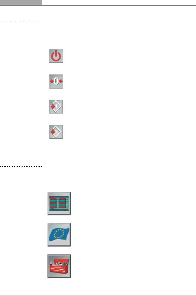
|
Standby |
Use this button to place the unit in standby |
|
mode. |
|
|
|
|
|
|
|
|
Zero- |
Use this button to manually initiate a zero- |
|
calibration |
calibration (see 6.2: ‘Start-Up’). |
|
|
|
|
|
Indicates that limit set 1 is currently applied; click |
|
Toggle Limits 1 |
to toggle to limit set 2; (see 8.2: ‘Free |
|
Measurement Vehicle Setup’ and 8.5: ‘Free |
|
|
|
|
|
|
Measurement Test Procedure’). |
|
|
|
|
|
Indicates that limit set 2 is currently applied: click |
|
Toggle Limits 2 |
to toggle to limit set 1; (see 8.2: ‘Free |
|
Measurement Vehicle Setup’ and 8.5: ‘Free |
|
|
|
|
|
|
Measurement Test Procedure’). |
|
|
|
|
|
|
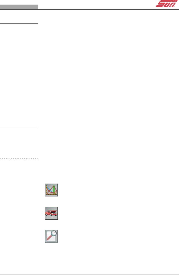
Table 4-2 Gas Analyser Menu Icons
Icon |
Name |
Description |
|
|
|
|
Free |
Selects the Free Measurement Program (see |
|
||
|
8: ‘Operation – The Free Measurement |
|
|
Measurement |
|
|
Procedure’) |
|
|
|
|
|
|
|
|
|
|
|
EU |
Selects the EU test procedure (see |
|
||
|
9: ‘Operation – The SUN EEC Test |
|
|
|
Procedure’)1 |
|
|
|
|
|
|
|
Gas Analyser |
Selects the The Gas Analyser System Menu |
|
||
|
System Setup |
|
|
|
|
|
|
|
|
|
|
18 |
DGA 2500 |
2002 - 11 |
GAS ANALYSER ICONS
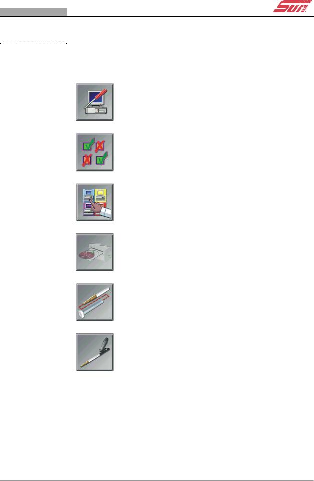
Table 4-2 Gas Analyser Menu Icons
Icon |
Name |
Description |
|
|
|
|
Maintenance |
Selects the Gas Analyser Maintenance Menu |
|
||
|
|
|
|
|
|
|
Setings |
Selects the Gas Analyser System Settings |
|
||
|
|
|
|
|
|
|
Gas Analyser |
|
|
|
|
|
System |
Selects Gas Analyser System Information |
|
Infomation |
|
|
|
|
|
|
|
|
Gas analyser |
Allows updated softwareto be loaded. |
|
||
|
Software |
|
|
Currently disabled. |
|
|
Update |
|
|
|
|
|
|
|
|
|
|
|
|
Initiates the Leak Check (Vacuum) |
|
Leak Check |
maintenance procedure. |
|
|
|
|
(Vacuum) |
|
|
|
|
|
|
|
|
Leak Check |
Initiates the Leak Check (Gas) maintenance |
|
||
|
(Gas) |
procedure. |
|
|
|
|
|
|
Doc. No.: ZEEEAGB132A Operator’s Manual Rev.: C |
19 |
C H A P T E R 4 FUNCTIONAL DESCRIPTION
Table 4-2 Gas Analyser Menu Icons
Icon |
Name |
Description |
|
|
|
|
Gas Calibration |
Initiates the Gas Calibration Check |
|
||
|
Check |
maintenance procedure. |
|
|
|
|
|
|
|
Check/install |
Initiates the Check and/or Install the O2 Cell |
|
||
|
O2 Cell |
maintenance procedure. |
|
|
|
|
|
|
1If a specific national test procedure is installed on the unit, the EU icon button will be replaced by the button relating to that procedure.
20 |
DGA 2500 |
2002 - 11 |

5 System and Gas Analyser
General Screens
This Chapter contains:
•A description of the DGA 2500 Gas Analyser System Screens. Gas Analyser System Screens are defined as being screens shown by the DGA 2500 that do not relate to a specific test procedure. These Screens comprise:
-The Gas Analyser Main Menu (5.1: ‘Gas Analyser Menu’).
-The Gas Analyser System Menu (5.2: ‘The Gas Analyser System Menu’).
-The Gas Analyser Maintenance Menu (5.3: ‘Gas Analyser Maintenance Menu’).
-The Gas Analyser System Settings Screen (5.4: ‘Gas Analyser System Settings’).
-The Gas Analyser System Information Window (5.5: ‘Gas Analyser System Information’).
•Details of the procedure to be followed in order to obtain a printout of the DGA 2500 gas analysis test results (5.6: ‘Print’).
Descriptions of the SUN® Diagnostic Platfrom Startup and General System Setup screens may be found in the Diagnostic Platform Operator’s Manual (5.1: ‘The Diagnostic Platform Main Menu’ & 5.2: ‘The General System Setup Screen’).
Doc. No.: ZEEEAGB132A Operator’s Manual |
21 |
C H A P T E R 5 SYSTEM AND GAS ANALYSER GENERAL SCREENS
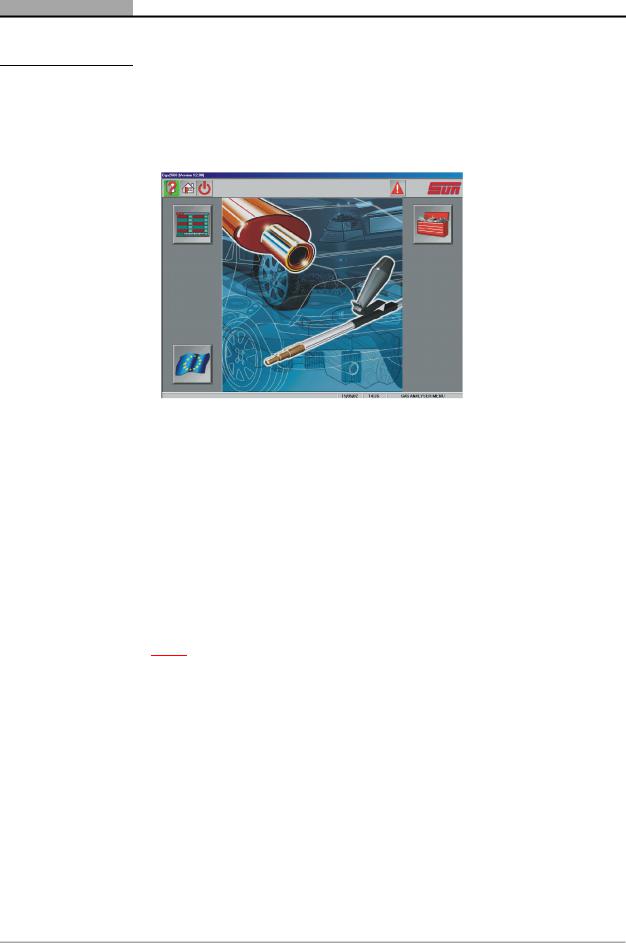
5.1 Gas Analyser Menu
.
Figure 5-1 The Gas Analyser Menu
•To access the Gas Analyser Menu , select the “Gas Analyser” option from The Diagnostic Platform Main Menu (see the SUN® Diagnostic Platform Operator’s Manual 5.1: ‘The Diagnostic Platform Main Menu’).
The following options may be selected:
-Free Measurement Procedure.
-SUN EEC Test Procedure.
-The Gas Analyser System Setup Menu.
Note:
pIf the DGA 2500 is configured to perform a country specific test procedure, the SUN EEC test procedure will not be available. In this case the “SUN EEC Test” button will be replaced by an icon button corresponding to the country specific test in question.
• The “Free Measurement” procedure.
The Free Measurement procedure continuously measures and displays the values for all available test parameters. Upper and lower limits for any or all of these parameters may be introduced as required. Refer to 8: ‘Operation – The Free Measurement Procedure’for further information.
• The “SUN EEC Test” procedure.
22 |
DGA 2500 |
2002 - 11 |

GAS ANALYSER MENU
The SUN EEC Procedure is based on the provisions of EU directives which specify a procedure to be followed in testing motor vehicle emissions and prescribes maximum default values for certain gas emissions and related parameters. Refer to 9: ‘Operation – The SUN EEC Test Procedure’.
• The “System Setup” option.
The The Gas Analyser System Menu allows operator maintenance functions to be initiated, gas analyser system settings to be made, gas analyser system information to be consulted and updates to the gas analyser software to be loaded. Refer to 5.2: ‘The Gas Analyser System Menu’ for further information.
•To return to the The Diagnostic Platform Main Menu, press the “Home” icon button on the toolbar.
•To place the Gas Analyser in Standby Mode, press the “Standby” icon button on the toolbar.
Once the Gas Analyser is switched on, it should remain on for the whole working day, however, it is recommended that the unit should be put into Standby Mode when tests are not being performed. This will reduce waer and tear to the pump and increase the effecive life of the filters.
The unit will return to the normal operating mode when:
-The “Standby” button is pressed once more, or
-One of the Gas Analyser Main Menu option buttons (“Free Measurement”, “SUN EEC Test” “Country Specific Test”, or “System Setup”) is pressed.
On leaving the Standby Mode, a Zero-calibration (see 6.2.4) and HC Residue Check (see 6.4) will automatically be performed before the unit returns to normal operation.
Doc. No.: ZEEEAGB132A Operator’s Manual Rev.: C |
23 |
C H A P T E R 5 SYSTEM AND GAS ANALYSER GENERAL SCREENS
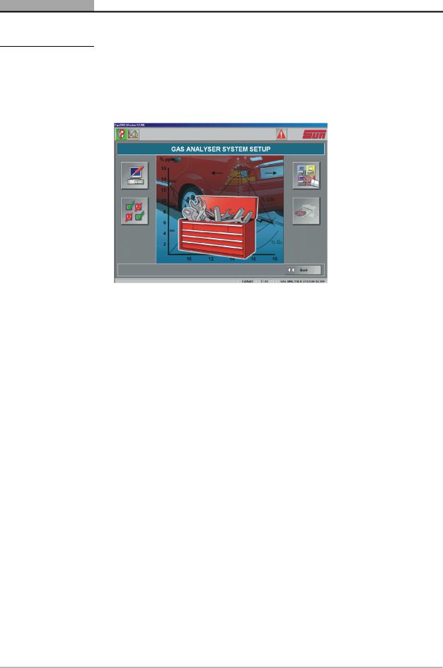
5.2 The Gas Analyser System Menu
Figure 5-2 The Gas Analyser System Menu
•To access the Gas Analyser System Menu , select the “System Setup” option from the Gas Analyser Menu (see 5.1).
The Gas Analyser System Menu allows access to:
-The Gas Analyser Operator Maintenance Procedures.
-The Gas Analyser System Settings Screen.
-The Gas Analyser System Information Screen.
-The Gas Analyser Software Update Screen.
•To access the Gas Analyser Maintenance Menu, select the “Maintenance” menu button.
The Gas Analyser Maintenance Menu Screen will be displayed, via which leak checks, gas calibration checks and O2 sensor checks can be initiated. Refer to 5.3 for a description of the Maintenance Menu Screen and to Chapter 10: ‘Maintenance’for details of the available maintenance procedures.
•To access the Gas Analyser System Settings Screen, select the “System Settings” option.
The System Settings Screen allows settings to be made affecting the operation of the gas Analyser. Refer to 5.4 for further information.
•To reveal the Gas Analyser System Information window, select the “System Information” option.
24 |
DGA 2500 |
2002 - 11 |
Loading...