


 Loading...
Radon Monitor User’s Guide
Accurate, Reliable, Economical
Models 1028, 1029

User’s Guide, Radon Monitor
© Copyright 2016 by Sun Nuclear Corporation. All rights reserved.
The information contained in this guide and the accompanying software program are copyrighted and all rights are reserved by Sun Nuclear Corporation. No part of this guide may be translated, reproduced, sold, or otherwise distributed without the prior written consent of Sun Nuclear Corporation.
Sun Nuclear Corporation reserves the right to make periodic modifications of this guide without obligation to notify any person or entity of such revision.
This guide is written for: |
|
PC software: |
version 2.2.0 |
Embedded firmware: |
version 1.0.9 |
Document 1028011, Rev I, 18 August 2017
Sun Nuclear Corporation 3275 Suntree Boulevard Melbourne, FL 32940 USA +1 321-259-6862 www.sunnuclear.com
ii
Preface
Description
The Continuous Radon Monitor is a detection device used to measure the concentration of radon gas. The unit is designed for professional inspectors to use in homes and buildings. The device is EPA verified and radon proficiency programs approved.
CAUTION: The Continuous Radon Monitor Model 1028 is intended to be used only for indoor applications of radon gas sampling. Using in an outdoor environment may cause errors due to humidity and extreme temperatures.
Health and Safety Instructions
WARNING: To avoid risk of electric shock, this device must only be connected to a supply mains with protective earth (ground).
WARNING: Never use the device in an area that could contain explosive gases. A spark from inside the device could ignite an explosion.
To protect Radon Monitor performance and cable insulation, never pull on a cable to disconnect it. Always grasp the plug or connector.
Do not permit water or any other liquids to spill onto the device.
For instructions to report health or safety related concerns, see Reporting Health or Safety Related Issues or Concerns on page 56.
iii

Finding Additional Information
The U.S. Environmental Protection Agency (EPA) maintains a comprehensive radon website at http://www.epa.gov/radon/index.html where you can find EPA documents, brochures, and publications relating to radon, including:
•A Citizen's Guide to Radon: The Guide to Protecting Yourself and Your Family from Radon. This guidance offers strategies for testing your home for radon and discussions of what steps to take after you have tested, as well as discussions about the risk of radon and radon myths.
•Consumer's Guide to Radon Reduction: How to Fix Your Home. This booklet is for people who have tested their home for radon and confirmed that they have elevated radon levels. This booklet can help with selecting a qualified contractor to reduce the radon levels in the home, determining an appropriate radon reduction method, and maintaining a radon reduction system.
•Home Buyer's and Seller's Guide to Radon. This booklet is intended for anyone who is buying or selling a home, real estate and relocation professionals, home inspectors and others.
iv
Contents
Preface . . . . . . . . . . . . . . . . . . . . . . iii
Description . . . . . . . . . . . . . . . . . . . . . iii Health and Safety Instructions . . . . . iii Finding Additional Information . . . . . iv
Introduction . . . . . . . . . . . . . . . . . . 1
Parts . . . . . . . . . . . . . . . . . . . . . . . . . . .1 Options and Accessories . . . . . . . . .2 Connections . . . . . . . . . . . . . . . . . . . . .3 Controls . . . . . . . . . . . . . . . . . . . . . . . .4
Standalone Operation . . . . . . . . . . 5
Position the Monitor . . . . . . . . . . . . . .5 Install a Fresh Battery . . . . . . . . . . . . .5 Replacing the 9V Battery . . . . . . . . .6 Connecting the AC Adapter . . . . . . .7 Turn on the Display . . . . . . . . . . . . . . .7 Starting a Test . . . . . . . . . . . . . . . . . . .9 Interrupting a Test . . . . . . . . . . . . . . . .9 Displaying Average and Current . . . .10 AVG or CUR During a Test . . . . . . .10 AVG or CUR After Test . . . . . . . . .10 Clearing Memory . . . . . . . . . . . . . . . .11 Checking Unit Status . . . . . . . . . . . . .11 Setting Up Parameters . . . . . . . . . . .12 Character Set . . . . . . . . . . . . . . . . . . .14 Display Turns Off Automatically . . . .14 Clearing a Reset . . . . . . . . . . . . . . . . .15 Low Battery Messages . . . . . . . . . . .15
Low Battery with AC Power Connected . . . . . . . . . . . . . . . . . . .15 Low Battery Without AC Power Connected . . . . . . . . . . . . . . . . . . .16
Storage Under Power . . . . . . . . . . . .16
Portable Printer (Optional) . . . . . 17
Printer - Parts . . . . . . . . . . . . . . . . . . .17 Printer - Description . . . . . . . . . . . . . .17 Printer Connection and Controls . . . .18 Loading the Paper . . . . . . . . . . . . . . .19 Printing a Report . . . . . . . . . . . . . . . .20 Typical Printer Report . . . . . . . . . . . .21
Movement . . . . . . . . . . . . . . . . . . .22 Printer Battery Pack . . . . . . . . . . . . . .22 Inserting the Battery Pack . . . . . . .22 Removing the Battery Pack . . . . . .22 Charging the Battery Pack . . . . . . .23 Low Printer Battery Indication . . . .23 Efficient Use of Printer Battery . . .23
Printer Switch Settings . . . . . . . . . . . 24
Computer Operation . . . . . . . . . . 26
About the Software . . . . . . . . . . . . . 26 Set Up Software . . . . . . . . . . . . . . . . 26 Prerequisites . . . . . . . . . . . . . . . . . 26 Install Software . . . . . . . . . . . . . . . 26 Connecting to Computer . . . . . . . . . 27 Launch Software . . . . . . . . . . . . . . . 27 Using Software to Retrieve Data . 28 Closing Software . . . . . . . . . . . . . . . 28 About the Main Screen . . . . . . . . . . . 29 Main Screen - Inspection Tab . . . . . . 29 Main Screen - Chart Tab . . . . . . . . . . 32 Zooming In and Out . . . . . . . . . . . 33 Moving the Chart . . . . . . . . . . . . . 33 Main Screen - Pictures Tab . . . . . . . 34 Main Screen - Checklist Tab . . . . . . . 35 Menu Bar and Toolbar Functions . . . 36 Data to/from Text File . . . . . . . . . . 37 Monitor Settings Preferences . . . . . 38
Preferences Screen - Monitor Settings Tab Details . . . . . . . . 39
Report Printing Preferences . . . . . . . 40 Preferences Screen – Print Tab
Details . . . . . . . . . . . . . . . . . . . 42 Printing Reports . . . . . . . . . . . . . . . . 44
Specifications . . . . . . . . . . . . . . . . 46
Recommended System
Requirements . . . . . . . . . . . . . . . 46 Models 1028 and 1029
Specifications . . . . . . . . . . . . . . . 46
Support and Maintenance . . . . . 48
Maintaining Hardware . . . . . . . . . . . 48 Repairs . . . . . . . . . . . . . . . . . . . . . 48 Inspection . . . . . . . . . . . . . . . . . . . 48 Storage . . . . . . . . . . . . . . . . . . . . . 48 Cleaning . . . . . . . . . . . . . . . . . . . . 48 Disposing and Recycling . . . . . . . 48 Service and Calibration . . . . . . . . . 49 Battery Life . . . . . . . . . . . . . . . . . . 49
Maintaining Software . . . . . . . . . . . . 49 Verifying Software Version . . . . . . 49 Removing Software . . . . . . . . . . . 49 Multiple Software Installations . . . 49 Optional Serial Connection . . . . . . . . 50 Serial Port Setup . . . . . . . . . . . . . . 50
v
Connecting with a Serial Cable . . .50 Port Selection . . . . . . . . . . . . . . . .51 Radon Monitor Troubleshooting . . . .51 System Errors . . . . . . . . . . . . . . . .52 Contacting Sun Nuclear Support . . . .54 Support Website . . . . . . . . . . . . . .54 Warranty . . . . . . . . . . . . . . . . . . . . . .54
Regulatory Supplement . . . . . . . 55
Sun Nuclear Corporation Symbols . . 55 Operator Responsibility . . . . . . . . . . 56 Reporting Health or Safety Related
Issues or Concerns . . . . . . . . . . . 56 Modifications to Equipment . . . . . . . 56 Interaction with Other Electrical
Equipment . . . . . . . . . . . . . . . . . . 56
vi
Introduction
Parts
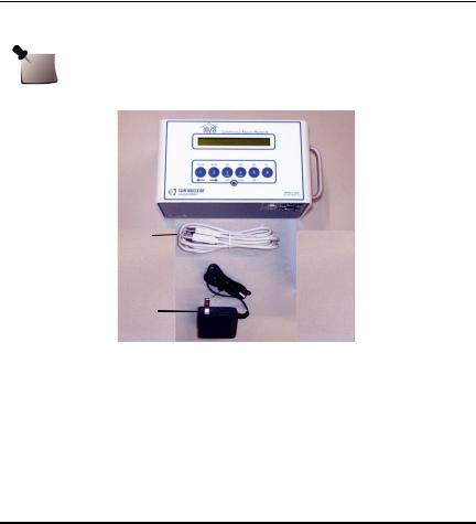
Unpack the radon monitor and identify the parts described below.
Note: Save the packing material so it can be used when sending the radon monitor to Sun Nuclear Corporation for annual re-calibration.
1
2
|
3 |
|
|
|
|
|
|
No. |
Part Number |
|
Description |
1 |
1028300 or |
Model 1028 |
Radon Monitor* or |
|
1028300-RM |
Model 1028 |
Radon Monitor (Refurbished) |
2 |
801041Z |
Cable, USB A-B M, 2 m |
|
|
|
|
|
3 |
741011** |
Power supply, 18 VDC, 100-240 VAC, 0.3A |
|
|
|
|
|
— |
0200014 |
Radon Customer Support Site letter (not shown) |
|
|
|
|
|
— |
1028012 |
Getting Started Guide (not shown) |
|
|
|
|
|
* Model 1029 Radon Monitor is obsolete.
**Power supply P/N 741011 is only included with Model 1028 Radon Monitors shipped within the United States.
Figure 1. Parts Furnished with Model 1028 Radon Monitor
1
Options and Accessories
Contact Sun Nuclear Corporation to order any of the following accessories:
Table 1. Radon Monitor Accessories
Part Number |
Description |
|
|
1028050 |
Printer, thermal, 80 column, Seiko DPU-414. |
|
|
022005Z |
Power supply for printer, 6 VDC. Used with P/N 801008Z. |
|
|
750052 |
Rechargeable battery pack for printer (furnished with P/N 1028050 or |
|
can be ordered separately). |
|
|
801008Z |
Line power cord for printer. Detachable, IEC Plug to USA style, 1.8 m. |
|
|
801032Z |
Serial cable for printer, 9-pin, D-connector, M/F (furnished with |
|
P/N 1028050 or can be ordered separately). |
|
|
850043Z |
Thermal paper for printer (furnished with P/N 1028050 or can be |
|
ordered separately). |
|
|
750004 |
Battery, alkaline, 9V, for radon monitor. |
|
|
741011 |
Power converter for Radon Monitors shipped within the United States, |
|
120 VAC to 12 VDC, 200 MA, 60 Hz. |
|
|
801041Z |
USB cable for Radon Monitor, 2 m. |
|
|
1028012 |
Radon Monitor Getting Started Guide. |
|
|
1028000-SC |
Carrying case, single radon monitor. |
|
|
1028000-SPC |
Carrying case, single radon monitor plus printer. |
|
|
1028000-DC |
Carrying case, dual (holds two radon monitors, printer, cables). |
|
|
102378 |
Sign, self-adhesive, “Warning, Closed Building Procedure”. |
|
|
102379 |
Sign, plastic, hanging, “Caution, Radon Test in Progress”. |
|
|
1028130 |
Sign, vinyl static cling, “Warning, Closed Building Procedure”. |
|
|
2
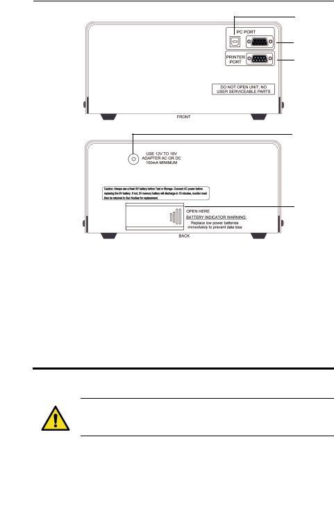
Connections
1
2
3
4
5
No |
Description |
Function |
|
|
|
1 |
USB PC PORT (front) |
USB port (USB 1.1 or 2.0); for connection to a computer |
|
|
|
2 |
Serial PC PORT (front) |
Serial port (RS-232); for connection to a computer |
|
|
|
3 |
PRINTER PORT (front) |
Serial port (RS-232); for connection to the optional printer. |
|
|
|
4 |
Power connection |
Power connector; connects to the power supply when |
|
(back) |
using AC power. |
|
|
|
5 |
Battery compartment |
Insert and connect a fresh 9V battery for either backup or |
|
(back) |
primary power. A fresh alkaline battery will operate the |
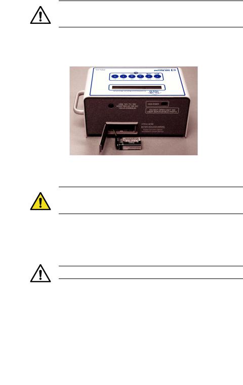
radon monitor for approximately 100 hours while a fresh lithium battery will provide about 300 hours of operation. See Replacing the 9V Battery on page 6.
Figure 2. Connections
WARNING: Always install a fresh 9V battery before test or storage to prevent the internal 3V battery (required for operation) from discharging.
3
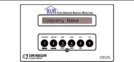
Controls
Description |
Function |
|
|
Display |
16-digit LCD display shows messages to guide the operation. |
|
|
Buttons |
Six push buttons with different functions depending on mode. Press keys |
|
to operate. Top row of labels lists main functions. Bottom row of labels are |
|
for Setup. Print and Clear functions are used after measurement. Numbers |
|
are for PIN entry and Setup. |
|
|
STATUS |
Selects the Status mode, which scrolls through the Status settings. |
|
|
SETUP |
Selects the Setup mode, which is used to enter setup values from the |
|
keypad. |
|
|
AVG |
Displays the measured cumulative average radon gas concentration in pCi/l |
|
or Bq/m3 since the memory was last cleared. |
CUR |
Displays the measured short-term radon gas concentration, a rolling aver- |
|
age of the most recent 12 hours. |
|
|
ON |
Press to turn on the display. There is no OFF switch. To save power, the dis- |
|
play turns off automatically after a few minutes of inactivity. |
|
|
ALT |
For future use. |
|
|
PIN |
Press to enter PIN (personal identification number), if used. |
|
|
SAVE |
Saves the Setup mode values that were entered. |
|
|
EDIT |
Allows editing of the Setup mode entries. |
|
|
Right arrow |
Scrolls ahead during Setup or Status. |
|
|
Left arrow |
Scrolls backward during Setup or Status. |
|
|
Clear |
Clears the test memory in Print/Clear mode. Memory must be cleared |
|
before starting a new test. |
|
|
Sends report data to optional printer in Print/Clear mode. |
|
|
|
Mode light |
The green light between EDIT and SAVE has the following meaning: |
|
• Blinks once during power up, indicating that the startup test is in prog- |
|
ress. |
|
• Blinks when radon is detected. |
|
|
|
Figure 3. Controls |
4
Standalone Operation
Position the Monitor
1Place the radon monitor in the desired position in the area to be monitored for radon gas. The radon monitor does not need to be level.
2To use a tripod, thread the standard tripod screw (1/4-20UNC) into the threaded fitting on the bottom of the case (Figure 4).
Figure 4. Using a Tripod
Install a Fresh Battery
The radon monitor can be operated on battery power or AC power. When connected to AC power, the battery provides back-up power. However, even when operating on AC power, a battery must be installed to provide backup power.
WARNING: Always install a fresh 9V battery before test or storage, even when the unit is connected to AC power, to prevent the internal 3V battery from discharging. The 3V battery will discharge in 15 minutes; the battery is not user-serviceable and if discharged, the unit must be returned to Sun Nuclear for replacement.
With the radon monitor disconnected from AC power, a fresh alkaline battery will operate the device for about 100 hours, or a fresh lithium-ion battery for about 300 hours.
5
CAUTION: High humidity may shorten battery life. Connect the AC power adapter when using the radon monitor in areas with high humidity.
The battery is located in a small compartment on the back of the radon monitor (Figure 5). To install a new battery, Replacing the 9V Battery, below. A replacement 9V battery can be purchased from Sun Nuclear or any retail source.
Figure 5. Inserting a Battery
Replacing the 9V Battery
WARNING: Always connect to AC power before replacing the 9V battery, to prevent the internal 3V battery (required for operation) from discharging.
The internal 3V battery will discharge in 15 minutes and if discharged, the unit must be returned to Sun Nuclear for replacement. Additionally, if the 3V internal battery is discharged, the time and date may be reset and the “Current” values may be permanently erased.
CAUTION: Never replace the battery during a test.
1If a test is in progress, wait for the test to complete.
2Connect the radon monitor to AC power using the AC adapter. See
Connecting the AC Adapter on page 7.
3Open the battery compartment door (Figure 5) on the rear panel of the unit.
4Remove the old battery and unsnap the connector.
6
5Connect a fresh 9V battery to the connector, insert the battery into the battery compartment, and close the battery compartment door.
Connecting the AC Adapter
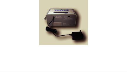
1After verifying a battery is installed (see Figure 5 on page 6), connect the power cable to the power connector on the rear panel of the radon monitor.
Figure 6. Connecting Power to the Radon Monitor
2Plug one end of the power cord into the adapter and the other end into a 100 to 240 VAC, 1-phase, 50-60 Hz mains power source.
Turn on the Display
To conserve power, the 16-digit display is always off until the ON button is pressed. If no buttons are pressed for 2 – 3 minutes, the display turns off automatically.
To turn the display on:
1Press the ON button (5). After a few seconds, the display turns on and shows the message “Battery OK” (Figure 7).
2If a Personal Identification Number (PIN) is set up, the display prompts the user to enter it. The company name is displayed momentarily (if set up) followed by the message “Checking Memory.” If there is data in memory, the message “Data in Memory!” appears. The data can be printed before clearing the memory.
7
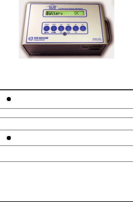
Figure 7. Turning on the Display
3When the display shows “Start Test = 5,” the user may start a new test, check AVG, check CUR, check STATUS, or change SETUP. The table below summarizes the steps to turn on the display.
Press…* Display Shows… |
Comment |
Display is always off until ON key (5) is pressed. “Battery OK” means there is enough power for 60 hours of
Battery OK operation (delay plus test). “Low/No Battery!” means that the battery has less than 60 hours operating life, or there is no battery installed.
– |
Enter PIN |
Only appears if a Personal Identification Number has |
|
been set up. |
|||
|
|
||
nnnn |
NNNN |
Enter PIN using digits 1 – 4 (5 and 6 not supported; |
|
there are no buttons for 7 – 9). Numbers entered are |
|||
|
|
displayed. Enter “5' after entering PIN. |
|
|
|
Press PIN button (5). If correct PIN was entered, com- |
|
|
Company Name |
pany name (if set up) displays. If wrong PIN was |
|
|
entered, message “Shutting down...” appears briefly |
||
|
|
||
|
|
and then display turns off. |
|
|
Checking |
If data is in memory, the messages “Data in Memory!” |
|
– |
and “Print and Clear” are displayed. Print and Clear the |
||
Memory |
memory before starting a new test. See Clearing Mem- |
||
|
|||
|
|
ory on page 11. |
With the display reading “Start Test = 5,” the user can press a button to:
• Start a test. See Starting a Test on page 9.
• Check AVG or CUR. See Displaying Average and Current on page 10.
– Start Test = 5 • Check STATUS. See Checking Unit Status on page 11.
•SETUP the unit. See Setting Up Parameters on page 12.
After a few minutes of inactivity, the display turns off automatically to save power.
8
Starting a Test
When the “Start Test = 5” prompt appears, press the 5 button to start a new test.
Press… |
Display Shows… |
Comment |
|||
– |
Start Test = 5 |
|
A new test can be started. |
||
|
Checking Memory |
Memory is rechecked. If data is found, memory |
|||
|
must be cleared before starting a new test. See |
||||
|
|
|
|
Clearing Memory on page 11. |
|
– |
Delay |
0 |
hr |
Displays the time delay defined in Setup. |
|
– |
Interval |
1 |
hr |
Displays the measurement interval defined in |
|
Setup. |
|||||
|
|
|
|
||
– |
Duration |
12 |
hr |
Displays the test duration defined in Setup. |
|
|
|
|
|
The test has started and will be finished after the |
|
– |
Test in Progress |
duration defined in Setup (plus delay). The display |
|||
turns off after a few minutes and remains off until |
|||||
|
|
|
|
||
the test is interrupted or the display is turned on.
Interrupting a Test
A test in progress can be interrupted to view the average or current readings. After the interruption, the test can be terminated or continued.
Press… |
Display Shows… |
Comment |
|
|
Battery OK |
Display turns on and battery is checked. |
|
– |
Enter PIN |
This prompt only appears if a Personal Identification |
|
Number was set up. |
|||
|
|
||
nnnn |
NNNN |
Enter the PIN using only digits 1 through 4. |
PIN number is displayed. Press PIN button (5) to NNNN check PIN. If the wrong PIN is entered, the mes-
sage “Shutting down...” is displayed.
|
|
|
Press 5 to end a test prematurely or 2 to continue. |
|
|
|
Pressing 2 will turn off the display and continue the |
|
|
|
test. |
– |
End Test |
Y=5 N=2 |
Note, when this message is displayed, the user |
|
|
|
also has the option to press AVG (3) or CUR (4) to |
|
|
|
display the average or current readings. See AVG or |
|
|
|
CUR During a Test, below. |
|
Confirm |
Y=5 N=2 |
Press 5 to confirm or 2 to cancel. |
|
Test Complete |
The test is terminated. |
|
A new test may be started. If there is partial test
– Start Test = 5 data in memory, it must be cleared before starting a new test. See Clearing Memory on page 11.
9
Note: A completed test cannot be interrupted. After a test is completed, pressing ON displays the normal start sequence.
Displaying Average and Current
Note: AVG is the average radon concentration over the total monitoring period; CUR is the average radon concentration over the last 12-hour period.
AVG or CUR During a Test
The average (AVG) or current (CUR) radon values can be displayed during a test. Turn ON the display (see Interrupting a Test on page 9), and note the button press options in the table below.
Press… |
Display Shows… |
Comment |
||
– |
End Test Y=5 N=2 |
When the display shows this message, press |
||
AVG (3) or CUR (4) to access those functions. |
||||
|
|
|
||
|
Hold 3&4 Prt/Clr |
This message only appears for a moment after |
||
or |
pressing 3 or 4. If the test was just started, the |
|||
|
|
|
message “Not Enough Data” is displayed. |
|
– |
Average |
1.2 |
If AVG (3) was pressed, radon monitor displays |
|
the average radon concentration over the total |
||||
|
|
|
monitoring period. |
|
– |
Current |
1.2 |
If CUR (4) was pressed, radon monitor displays |
|
the radon concentration in the current 12-hour |
||||
|
|
|
period. |
|
– |
Shutting down... |
After displaying AVG or CUR, monitor shuts |
||
down to resume test. |
||||
|
|
|
||
AVG or CUR After Test
The average (AVG) and current (CUR) radon values can also be displayed after a test is completed. Turn ON the display (see Turn on the Display on page 7), and note the button press options in the table below.
Press… |
Display Shows… |
Comment |
||
|
Start Test = 5 |
Press AVG (3) or CUR (4). |
||
|
Hold 3&4 Prt/Clr |
This message only appears for a moment after |
||
|
pressing AVG (3). |
|||
|
|
|
||
– |
Average |
1.2 |
Displays the average radon concentration over |
|
the total monitoring period. |
||||
|
|
|
||
Hold 3&4 Prt/Clr |
This message only appears for a moment after |
|
pressing CUR (4). |
||
|
10
Press… |
Display Shows… |
Comment |
||
|
|
|
|
|
– |
Current |
1.2 |
Displays the radon concentration in the current |
|
12-hour period. |
||||
|
|
|
||
|
|
|
|
|
|
|
|
AVG or CUR reading is complete. The data for the |
|
– |
Start Test = 5 |
test remains in memory and must be cleared |
||
before starting a new test. See Starting a Test on |
||||
|
|
|
||
page 9.
Clearing Memory
After printing the report, clear the memory using the key press options in the table below.
Press… |
Display Shows… |
Comment |
|
– |
Start Test = 5 |
It is recommended to print a report before clear- |
|
ing data. |
|||
|
|
||
|
|
When the “Start Test = 5” message appears, |
|
+ |
Prt=3 Cl=4 Ex=5 |
press and hold 3 and 4. Keep holding until the |
|
“Prt=3 Cl=4 Ex=5” message appears. Press 4 to |
|||
|
|||
|
|
clear (or 5 to exit). |
|
|
Confirm Y=5 N=2 |
Press 5 to confirm the clear memory command. |
|
|
Clearing Memory |
The memory is cleared in a few seconds. |
Checking Unit Status
Before starting a new test, it is recommended to scroll through the status items to confirm they are correct.
Press… |
Display Shows… |
Comment |
||||
– |
Start Test = 5 |
The status menu can be selected when the display |
||||
shows “Start Test = 5.” |
||||||
|
|
|
|
|
||
|
Status Menu |
Press the (1) button to select the status menu. The |
||||
|
status of each item will scroll through automati- |
|||||
|
|
|
|
|
cally. Each item displays for about 2 seconds. |
|
– |
DELAY |
|
|
nn hr |
The delay time selected. |
|
– |
INTERVAL |
|
nn hr |
The measurement interval selected. |
||
– |
DURATION |
|
nnn hr |
The duration of the test. |
||
– |
BATTERY |
|
Ok |
Battery status. |
||
– |
TIME |
|
nn:nn PM |
Current time. |
||
– |
DATE |
|
MM DD YY |
Current date |
||
– |
CAL |
MM/DD/YYYY |
Date of last calibration. |
|||
– |
SNC MODEL |
1028 |
Model number. |
|||
11
Press… |
Display Shows… |
Comment |
|||
|
|
|
|
|
|
– |
CODE |
VER |
nnnn |
Embedded code (firmware) version number. |
|
|
|
|
|
||
– |
S/N |
nnnnnnnnnnn |
Serial number. |
||
|
|
|
|
|
|
– |
Status Menu Done |
End of the menu. Display returns to “Start Test = |
|||
5”. |
|||||
|
|
|
|
||
Status items can also be displayed during a test by pressing the (1) button while the display shows “End Test Y=5 N=2.”
Setting Up Parameters
Note: If there is any test data in the radon monitor, parameters cannot be entered. Clear test data before changing parameters.
Parameter data can be entered using a computer or by entering the characters with the front panel keys on the radon monitor. Using a computer is the faster of the two methods. For instructions to enter parameter data using a computer, see Monitor Settings Preferences on page 38. The table below shows the parameter key press options.
Press… |
Display Shows… |
Comment |
||
– |
Start Test = 5 |
Parameters can be changed at any time before |
||
starting a test. |
||||
|
|
|
||
|
Setup Menu |
|
Entering setup menu. |
|
– |
Checking Memory |
Checking memory for data. |
||
– |
Delay |
0.0 hr |
Shows current delay settings. |
|
|
|
|
Press arrow buttons to change value. |
|
|
|
|
• If the monitor firmware version is 106 or higher, |
|
|
|
|
the delay options are 0.0 hours,12 hours, 24 |
|
|
|
|
hours, or 48 hours. |
|
|
|
|
• If the monitor firmware version is 105 or lower, |
|
|
|
|
the delay options are 0.0 hours or 12 hours. |
|
or |
Delay |
12 hr |
For the steps to check firmware version on a |
|
|
|
|
standalone monitor (not connected to a com- |
|
|
|
|
puter), see Checking Unit Status on page 11. For |
|
|
|
|
the steps to check the firmware version from the |
|
|
|
|
computer, see Monitor Settings Preferences on |
|
|
|
|
page 38. The serial number and firmware version |
|
|
|
|
of the unit are displayed on the right side of the |
|
|
|
|
Monitor Settings screen. |
|
|
Interval |
1.0 hr |
Press SAVE; saves the Delay setting and |
|
|
|
|
advances to Interval. |
|
|
Interval |
4.0 hr |
Press arrow keys to scroll through selection of |
|
or |
intervals, 0.5 (model 1029 only), 11.0, 2.0, 4.0, 8.0, |
|||
|
|
|
12,16, 20, or 24 hours. |
|
12

Press… |
Display Shows… |
Comment |
|
Duration 1.0 hr |
Press SAVE; saves the setting and advances to |
|
the next item. |
|
|
|
|
|
|
Press arrow keys to scroll through test duration |
|
Duration 48 hr |
times: 1.0, 12, 24, 36, 48, 60, 72, 84, 96, 100, or |
or |
999 hours. |
|
|
|
If 999 is selected, measures until memory is full or |
|
|
to 720 data points, whichever occurs first. |
|
COMPANY Company |
Press SAVE; saves the setting and advances to |
|
the next. |
|
|
|
|
|
COMPANY Company |
The EDIT key (3) lets you begin to edit the first |
|
character. |
|
|
|
Press the arrow keys to scroll through the avail-  or
or  COMPANY Mompany able characters. See Character Set on page 14 for a list of characters. Press and hold for rapid scroll.
|
|
|
Press EDIT key (3) and scroll to the next and sub- |
|
|
COMPANY My Comp |
sequent characters. Press EDIT (3) again to enter |
||
|
the next character. Continue character by charac- |
|||
|
|
|
ter until the company name is entered (up to 30 |
|
|
|
|
characters). |
|
|
ADDRESS1 none |
Press SAVE (4); saves the setting and advances to |
||
|
the next item. |
|||
|
|
|
||
|
|
|
The EDIT key (3) allows editing beginning with the |
|
|
ADDRESS1 9one |
first character. Enter up to 30 characters for the |
||
|
first address line using the same procedure as for |
|||
|
|
|
||
|
|
|
Company name. |
|
|
ADDRESS2 none |
Press SAVE (4); saves the setting and advances to |
||
|
the next item. |
|||
|
|
|
||
|
|
|
If a second address line is not needed, leave it |
|
|
ADDRESS2 none |
blank. The EDIT key (3) will allow editing begin- |
||
|
ning with the first character. Enter up to 30 |
|||
|
|
|
characters for the second address line using the |
|
|
|
|
same procedure as for Company name. |
|
|
City |
none |
Press SAVE (4); saves the setting and advances to |
|
|
the next item. |
|||
|
|
|
||
and |
City |
none |
Enter city (20 characters) and SAVE (4) (same as |
|
above). |
||||
|
|
|||
and |
STATE |
none |
Enter state (10 characters) and SAVE (4) (same as |
|
above). |
||||
|
|
|||
and |
ZIPCODE |
|
Enter zip code (10 characters) and SAVE (4) (same |
|
|
as above). |
|||
|
|
|||
and |
PHONE |
|
Enter phone number (20 characters) and SAVE (4) |
|
|
(same as above). |
|||
|
|
|||
and |
LICENSE |
|
Enter license number (10 characters) and SAVE (4) |
|
|
(same as above). |
|||
|
|
|||
and |
TIME |
|
Enter current time (4 numbers plus AM or PM) |
|
|
and SAVE (4) (same as above). |
|||
|
|
|||
and |
DATE |
|
Enter current date in the format MMDDYY (6 |
|
|
numbers) and SAVE (4) (same as above). |
|||
|
|
|||
13
Press… |
Display Shows… |
Comment |
|
and |
UNITS pC/l |
Select units, pCi/l or Bq/m3 (edit, select with |
|
arrows, and SAVE (4)). |
|||
|
|||
|
PIN NUM 1111 |
Enter a PIN number if desired in the range of 1111 |
|
and |
to 4444 and SAVE. The number 1111 is equivalent |
||
|
|
to no PIN. To clear a PIN, enter 1111. |
|
|
Setup Menu Done |
End of setup menu. |
To enter parameter data using the front panel keys on the radon monitor:
1Turn on unit.
2Press “Setup” (button 2).
3Advance through the list by pressing “Save” (4).
4Stop on an item to change it.
5Press “Edit” (3) to edit the item.
6Press the arrow keys to scroll through a list of available characters and stop when the desired character appears. Press and hold arrow key for fast scroll.
7When a desired character to change appears, press “Edit” (3) again to change it.
8When all the characters are changed, press “Edit” to complete the item.
9Press “Save” and advance to the next item.
Character Set
The available character set includes the following in the sequence shown:
(space) ! “ # $ % & ‘ ( ) * + , - . / 0 1 2 3 4 5 6 7 8 9 : ; < = > ? @ A B C D E F G H I J K L M N O P Q R S T U V W X Y Z [ \ ] ^ _ ‘ a b c d e f g h i j k l m n o p q r s t u b w x y z
Display Turns Off Automatically
The display turns off automatically after a period of inactivity of about 2-3 minutes. There is no OFF switch or key sequence.
14
Loading...