

Page 1
HIGH TECH SECURES YOUR FUTURE
DGA 2500
DGA 2500
DGA 2500DGA 2500
Diagnostic Gas Analyser
Operator’s Manual
Page 2

Page 3

Operator’s Manual
DGA 2500
DGA 2500
DGA 2500DGA 2500
Software Version V 2.1.0.14
Models: EEEA132
Diagnostic Gas Analyser
Copyright 2002 Snap-on UK Holdings Ltd.
All rights reserved
Part number : ZEEEAGB132A Rev.:C
PCN : 02 E 0293
Doc. No.: ZEEEAGB132A Operator’s Manual Rev.: C i
Page 4

Doc. No.: ZEEEAGB132A Operator’s Manual Rev.: C ii
Page 5

DISCLAIMER OF WARRANTIES AND
LIMITATIONS OF LIABILITIES
Whilst the authors have taken due care in the preparation of this manual,
nothing contained herein:
• modifies or alters in any way the standard terms and conditions of the
purchase, lease or rental agreement under the terms of which the
equipment to which this manual relates was acquired,
• increases in any way the liability to the customer or to third parties.
TO THE READER
Whilst every effort has been made to ensure that the information
contained in this manual is correct, complete and up-to date, the right to
change any part of this document at any time without prior notice is
reserved.
ä Before installing, maintaining or operating this unit, please read
this manual carefully, paying extra attention to the safety warnings
and precautions.
a
Copyright 2002 Snap-on UK Holdings Ltd
All Rights Reserved
Sun Electric Europe B.V.
Spaklerweg 69
1099 BB Amsterdam
The Netherlands
Tel: +31.20.5682.622
Fax: +31.20.6947.962
Web-site:
http://www.Sun-diagnostics.com
Doc. No.: ZEEEAGB132A Operator’s Manual Rev.: C iii
Page 6

iv DGA 2500 2002 - 11
Page 7

Table of Contents
Table of Contents . . . . . . . . . . . . . . . . . . . . . . . . . . . . . .1
Notes on User Documentation . . . . . . . . . . . . . . . . . . . .5
1 Safety . . . . . . . . . . . . . . . . . . . . . . . . . . . . . . . . . . . . . . . .7
1.1 Safety Notice . . . . . . . . . . . . . . . . . . . . . . . . . . . . . . . . . . . . . . . . . . . 7
1.1.1 Read all Instructions . . . . . . . . . . . . . . . . . . . . . . . . . . . . . . . 8
1.2 Conventions . . . . . . . . . . . . . . . . . . . . . . . . . . . . . . . . . . . . . . . . . . . . 8
2 Product Specification . . . . . . . . . . . . . . . . . . . . . . . . . . .9
2.1 General . . . . . . . . . . . . . . . . . . . . . . . . . . . . . . . . . . . . . . . . . . . . . . . 9
2.2 Gas Bench . . . . . . . . . . . . . . . . . . . . . . . . . . . . . . . . . . . . . . . . . . . . . 9
2.2.1 Propane Equivilance Factor . . . . . . . . . . . . . . . . . . . . . . . . 10
3 Introduction . . . . . . . . . . . . . . . . . . . . . . . . . . . . . . . . . . 11
3.1 The DGA 2500 . . . . . . . . . . . . . . . . . . . . . . . . . . . . . . . . . . . . . . . . . 11
3.2 Maintenance . . . . . . . . . . . . . . . . . . . . . . . . . . . . . . . . . . . . . . . . . . . 12
3.3 Options . . . . . . . . . . . . . . . . . . . . . . . . . . . . . . . . . . . . . . . . . . . . . . . 13
4 Functional Description . . . . . . . . . . . . . . . . . . . . . . . . .15
4.1 Platform Layout . . . . . . . . . . . . . . . . . . . . . . . . . . . . . . . . . . . . . . . . 15
4.2 Gas Module Layout . . . . . . . . . . . . . . . . . . . . . . . . . . . . . . . . . . . . . 15
4.3 Common Program Elements . . . . . . . . . . . . . . . . . . . . . . . . . . . . . . 17
4.4 Gas Analyser Icons . . . . . . . . . . . . . . . . . . . . . . . . . . . . . . . . . . . . . 17
5 System and Gas Analyser General Screens . . . . . . . .21
5.1 Gas Analyser Menu . . . . . . . . . . . . . . . . . . . . . . . . . . . . . . . . . . . . . 22
5.2 The Gas Analyser System Menu . . . . . . . . . . . . . . . . . . . . . . . . . . . 24
Doc. No.: ZEEEAGB132A Operator’s Manual 1
Page 8

TABLE OF CONTENTS
5.3 Gas Analyser Maintenance Menu . . . . . . . . . . . . . . . . . . . . . . . . . . .25
5.4 Gas Analyser System Settings . . . . . . . . . . . . . . . . . . . . . . . . . . . . .26
5.5 Gas Analyser System Information . . . . . . . . . . . . . . . . . . . . . . . . . .28
5.6 Print . . . . . . . . . . . . . . . . . . . . . . . . . . . . . . . . . . . . . . . . . . . . . . . . .29
6 Preparatory Steps . . . . . . . . . . . . . . . . . . . . . . . . . . . . . 31
6.1 Connections . . . . . . . . . . . . . . . . . . . . . . . . . . . . . . . . . . . . . . . . . . .31
6.1.1 Power Connections . . . . . . . . . . . . . . . . . . . . . . . . . . . . . . .31
6.1.2 Data Connections . . . . . . . . . . . . . . . . . . . . . . . . . . . . . . . .31
6.1.3 Gas Module Pneumatic Connections . . . . . . . . . . . . . . . . .32
6.2 Start-Up . . . . . . . . . . . . . . . . . . . . . . . . . . . . . . . . . . . . . . . . . . . . . . .32
6.2.1 Power Up . . . . . . . . . . . . . . . . . . . . . . . . . . . . . . . . . . . . . .32
6.2.2 Gas Analyser Start-up . . . . . . . . . . . . . . . . . . . . . . . . . . . . .33
6.2.3 Warm up . . . . . . . . . . . . . . . . . . . . . . . . . . . . . . . . . . . . . . .33
6.2.4 Zero-calibration . . . . . . . . . . . . . . . . . . . . . . . . . . . . . . . . . .34
6.3 Daily Leak Check . . . . . . . . . . . . . . . . . . . . . . . . . . . . . . . . . . . . . . .35
6.4 HC Residue Check . . . . . . . . . . . . . . . . . . . . . . . . . . . . . . . . . . . . . .36
6.5 Settings . . . . . . . . . . . . . . . . . . . . . . . . . . . . . . . . . . . . . . . . . . . . . . .37
6.5.1 Fuel Type Selection . . . . . . . . . . . . . . . . . . . . . . . . . . . . . .37
6.5.2 Speed Factor Setting . . . . . . . . . . . . . . . . . . . . . . . . . . . . .37
6.5.3 Lambda/AFR Selection . . . . . . . . . . . . . . . . . . . . . . . . . . . .37
6.6 Vehicle Connections . . . . . . . . . . . . . . . . . . . . . . . . . . . . . . . . . . . . .38
6.6.1 RPM Pick-Up . . . . . . . . . . . . . . . . . . . . . . . . . . . . . . . . . . .38
6.6.2 Oil Temperature Probe . . . . . . . . . . . . . . . . . . . . . . . . . . . .38
7 Operation — General . . . . . . . . . . . . . . . . . . . . . . . . . . 39
7.1 Testing Tips . . . . . . . . . . . . . . . . . . . . . . . . . . . . . . . . . . . . . . . . . . . .39
7.2 Measurement Procedure . . . . . . . . . . . . . . . . . . . . . . . . . . . . . . . . .40
7.3 Shut Down Procedure . . . . . . . . . . . . . . . . . . . . . . . . . . . . . . . . . . . .41
8 Operation – The Free Measurement Procedure . . . . .43
8.1 The Free Measurement Screen . . . . . . . . . . . . . . . . . . . . . . . . . . . .44
8.2 Free Measurement Vehicle Setup . . . . . . . . . . . . . . . . . . . . . . . . . .46
8.3 Saving and Loading Vehicle Setups . . . . . . . . . . . . . . . . . . . . . . . . .48
8.4 Editing Limit Sets . . . . . . . . . . . . . . . . . . . . . . . . . . . . . . . . . . . . . . .49
8.5 Free Measurement Test Procedure . . . . . . . . . . . . . . . . . . . . . . . . .50
8.6 Storing Data in the Data Buffers . . . . . . . . . . . . . . . . . . . . . . . . . . . .51
8.7 The Print Preview Window . . . . . . . . . . . . . . . . . . . . . . . . . . . . . . . .54
2 DGA 2500 2002 - 11
Page 9

8.8 Printing Test Results . . . . . . . . . . . . . . . . . . . . . . . . . . . . . . . . . . . . 55
9 Operation – The SUN EEC Test Procedure . . . . . . . . .57
9.1 Introduction . . . . . . . . . . . . . . . . . . . . . . . . . . . . . . . . . . . . . . . . . . . 57
9.2 SUN EEC Test Vehicle Set-up . . . . . . . . . . . . . . . . . . . . . . . . . . . . . 58
9.3 Editing Limit Sets . . . . . . . . . . . . . . . . . . . . . . . . . . . . . . . . . . . . . . . 61
9.4 Saving and Loading Vehicle Set-ups . . . . . . . . . . . . . . . . . . . . . . . . 62
9.5 Test Procedure Summary . . . . . . . . . . . . . . . . . . . . . . . . . . . . . . . . . 64
9.6 Initialization Phase . . . . . . . . . . . . . . . . . . . . . . . . . . . . . . . . . . . . . . 65
9.7 Fast Idle Preconditioning Phase . . . . . . . . . . . . . . . . . . . . . . . . . . . 66
9.8 Fast Idle Measurement Phase . . . . . . . . . . . . . . . . . . . . . . . . . . . . . 70
9.9 Normal Idle Preconditioning Phase . . . . . . . . . . . . . . . . . . . . . . . . . 72
9.10 Normal Idle Measurement Phase . . . . . . . . . . . . . . . . . . . . . . . . . . . 74
9.11 Results Phase . . . . . . . . . . . . . . . . . . . . . . . . . . . . . . . . . . . . . . . . . 78
10 Maintenance . . . . . . . . . . . . . . . . . . . . . . . . . . . . . . . . . . 81
10.1 System Checks . . . . . . . . . . . . . . . . . . . . . . . . . . . . . . . . . . . . . . . . 81
10.2 Leak Check (Vacuum) . . . . . . . . . . . . . . . . . . . . . . . . . . . . . . . . . . . 81
10.3 Leak Check (Gas) . . . . . . . . . . . . . . . . . . . . . . . . . . . . . . . . . . . . . . 84
10.4 Gas Calibration Check . . . . . . . . . . . . . . . . . . . . . . . . . . . . . . . . . . . 87
10.5 Check and/or Install the O2 Cell . . . . . . . . . . . . . . . . . . . . . . . . . . . 88
10.6 Routine Maintenance Procedures . . . . . . . . . . . . . . . . . . . . . . . . . . 92
10.6.1 Periodic Checks . . . . . . . . . . . . . . . . . . . . . . . . . . . . . . . . . 92
10.6.2 Filters . . . . . . . . . . . . . . . . . . . . . . . . . . . . . . . . . . . . . . . . . 92
10.6.3 Sample Probe and Hose . . . . . . . . . . . . . . . . . . . . . . . . . . 93
10.6.4 Test Leads . . . . . . . . . . . . . . . . . . . . . . . . . . . . . . . . . . . . . 94
10.6.5 O2 Cell . . . . . . . . . . . . . . . . . . . . . . . . . . . . . . . . . . . . . . . . 94
10.6.6 NO Cell (Optional) . . . . . . . . . . . . . . . . . . . . . . . . . . . . . . . 94
10.6.7 General . . . . . . . . . . . . . . . . . . . . . . . . . . . . . . . . . . . . . . . 95
10.7 Error, Warning and System Status Messages . . . . . . . . . . . . . . . . . 95
10.7.1 Automatic Pop-up Windows . . . . . . . . . . . . . . . . . . . . . . . . 95
10.8 The Error/Warning Button . . . . . . . . . . . . . . . . . . . . . . . . . . . . . . . . 97
10.9 Maintenance Parts . . . . . . . . . . . . . . . . . . . . . . . . . . . . . . . . . . . . . 100
Index . . . . . . . . . . . . . . . . . . . . . . . . . . . . . . . . . . . . . . .101
Doc. No.: ZEEEAGB132A Operator’s Manual Rev.: C 3
Page 10

TABLE OF CONTENTS
4 DGA 2500 2002 - 11
Page 11

Notes on User Documentation
The DGA 2500 user documentation contains instructions for the safe
operation and efficient use of the unit.
This important information is designed for the prevention of injury to the
operator and/or other persons and for the avoidance of damage to the
unit or vehicles connected thereto.
The user documentation comprises:
• The SUN
introduction to the SUN
safety and operating instructions that are common to all system
modules.
• The DGA 2500 Operator’s Manual describing the DGA 2500 module
in detail and providing instructions for carrying out complete Free
Measurement and SUN ECC vehicle test procedures.
• The appropriate Operator’s Manual or Manuals relating to any
jurisdiction specific test programs (e.g. MOT, AU etc.) that may be
installed.
Whilst no documentation is supplied in printed form, this documentation
is included on the CD-ROM and will be installed on the unit PC during
the installation of the software.
To access the documentation:
• press F1 on the keyboard or the F1 or help button on the remote
control.
or
• Click the “Help” button in the program toolbar.
® Diagnostic Platform Operator’s manual containing an
® Diagnostic Platform system together with
Doc. No.: ZEEEAGB132A Operator’s Manual 5
Page 12

C H A P T E R NOTES ON USER DOCUMENTATION
6 DGA 2500 2002 - 11
Page 13
1 Safety
All Safety Precautions relevant to the unit are described in the Safety
Precautions book, part number: EAZ0007E04A
Figure 1-1 part number: EAZ0007E04A
The Safety Precautions book should be fully understood by every
operator. We suggest that (a copy of) of the Safety Precautions book be
stored near the unit, in sight of the operator.
The Operator’s Manual will contain specific warnings and cautions when
possible dangerous situations may be encountered during the described
procedures.
1.1 Safety Notice
Read this manual thoroughly before operating the unit.
The unit is intended for use by properly trained, skilled professional
automotive technicians. The safety messages presented in the Safety
Precautions book and throughout this manual are reminders to the
operator to exercise extreme care when using this unit.
There are many variations in procedures, techniques, tools, and parts for
servicing vehicles, as well as in the skill of the individual doing the work.
Because of the vast number of test applications and variations in the
Doc. No.: ZEEEAGB132A Operator’s Manual 7
Page 14

C H A P T E R 1 SAFETY
products that can be tested with this instrument, we cannot possibly
anticipate or provide advice or safety messages to cover every situation.
It is the automotive technician’s responsibility to be knowledgeable of the
system being tested. It is essential to use proper service methods and
test procedures and to perform tests in an appropriate and acceptable
manner that does not endanger your safety, the safety of others in the
work area, or vehicle or equipment being tested.
It is assumed the operator has a thorough understanding of vehicle
systems before using the unit. Understanding of these system principles
and operating theories is necessary for competent, safe and accurate
use of this unit.
Before using the unit, always refer to and follow safety messages and
applicable test procedures provided by the manufacturer of the vehicle
or equipment being tested.
Warning:
Warning:
ä Use equipment only as described in the manual.
1.1.1 Read all Instructions
Read, understand and follow all safety messages and instructions in the
Safety Precautions book, this manual and on the unit.
1.2 Conventions
This manual contains text styles that ask you to pay extra attention:
Note:
p Suggestion or explaination.
Caution:
c Stresses that the following action may cause damage to the unit or
objects attached to it.
Warning:
Warning:
ä Stresses that the following action may cause (severe) injury to the
operator or others.
Warning:
Warning:
ä The operator must have full knowledge of all information stated in
the Operator’s Manual.
8 DGA 2500 2002 - 11
Page 15
2 Product Specification
2.1 General
Refer to the SUN® Diagnostic Platform Operator’s Manual for details of
the Power Supply (3.1: ‘Power Supply’) and Dimensions
(3.2: ‘Dimensions’) of the Diagnostic Platform and for the Minimum PC
Specifications (3.3: ‘Minimum PC Specifications’).
2.2 Gas Bench
Table 2-1 Operation & Storage
Operating Conditions
Max. ambient temp. +40 °C
Min. ambient temp. +5 °C
Rel. humidity: up to 90%, non-condensing
Max atmospheric
pressure variation
Storage Conditions
Temperature: -20 to +55 °C
Rel. humidity: Up to 90%, non-condensing
Table 2-2 Measurements
Parameter Range/
%vol CO: 0.000 – 9.999
%vol CO
: 0.00 – 18.00 ±5%/±0.5%*
2
700 – 1100 mbar
Accuracy: Relative/Absolute
Resolution
±5%/±0.03*
10.00 –14.00
Doc. No.: ZEEEAGB132A Operator’s Manual 9
Page 16
C H A P T E R 2 PRODUCT SPECIFICATION
Table 2-2 Measurements
Parameter Range/
Resolution
ppmvol HC: 0 – 2000
2000 – 5000
5000 – 9000
%vol O
ppmvol NO (option): 0 – 5000 ±5%/25ppm (at room temperature)
rpm 0 – 9999 ±1.0%
°C: 0 – 120
°F: 14 –302
: 0 – 25.00 ±5%/±0.1*
2
Accuracy: Relative/Absolute
±5%/10ppm*
±5%/10ppm
±10%
Note:
p *accuracy according to OIML Class 0
2.2.1 Propane Equivilance Factor
The P.E.F. value is 0.530.
10 DGA 2500 2002 - 11
Page 17

3 Introduction
3.1 The DGA 2500
The SUN® DGA 2500 is a versatile, high-performance PC-based test
instrument for the analysis of motor vehicle exhaust gases. The unit is
designed to meet the performance requirements of OIML Class 1 and 0
and ISO 3930.
The basic configuration of the unit comprises:
- A gas analysis module containing a Siemens “Sibench” gas
bench.
- A rpm/oil temperature module (ROTI) for the measurement of
engine speed and oil temperature. The unit is supplied with a
Grey inductive pick-up (P/N EAX0048E03A; for use with
conventional HT ignition systems) as standard equipment.
- An exhaust probe and hose assembly, used for the collection of
the gas sample from the vehicle tailpipe.
The DGA 2500 forms part of the SUN
Refer to the SUN
Diagnostic Platform’) for an introduction to the system as a whole.
The addition of an optional USB to 4 x RS232 connector enables a
smoke module, for testing diesel emissions, and a Portable Data Link,
used to obtain information from the vehicle engine management system,
to be connected to the system via the Gas Analyser. This connector can
also be used for external communication with, for example, the
customer’s central computer system.
Specific software versions will be available for performing the emissions
tests specified by separate national or international jurisdictions.
Although this jurisdiction specific software may alter the DGA 2500
standard software described herein, this manual is also applicable to
these specific programs when used in conjunction with the specific
documentation relating to such programs.
® Diagnostic Platform Operator’s Manual (2: ‘The SUN
® Diagnostic Platform System.
Doc. No.: ZEEEAGB132A Operator’s Manual 11
Page 18

C H A P T E R 3 INTRODUCTION
With the standard software the unit is capable of measuring the
concentrations of up to five gases in vehicle exhaust emissions:
- Carbon Monoxide, Carbon Dioxide and Hydrocarbons (CO, CO
and HC) by infra red absorption.
- Oxygen (O
- Oxides of Nitrogen (NO) by electrochemical cell. The NO cell is
optional and is NOT operator changeable.
In addition to the gas measurements the unit also displays:
- Lambda (λ) according to Brettschneider.
- Engine speed (rpm) via the ROTI module. An inductive rpm pickup, to be placed on a secondary ignition cable, is supplied as
standard equipment. A capacitive pick-up, for use on a primary or
injector wire, and a primary ECU/RPM adapter, for connection to
a square wave from the engine management system, are
available as options, thus making the analyser suitable for
conventional, wasted spark and direct ignition systems.
- Oil temperature via the ROTI module by means of an oil
temperature probe substituted for the oil dipstick.
Note:
) by an operator changeable electrochemical cell.
2
p In cases where a Portable Data Link is connected to the analyser, rpm
and oil temperature data will be obtained via the PDL.
2
CO corrigé (CO
type.
c) may be displayed using a formula corrected for fuel
3.2 Maintenance
Details of the maintenance operations that should be carried out by the
operator are included in this manual together with a list of operator
service messages and a list of maintenance parts.
All maintenance operations, other than those specifically described in
this manual, must be carried out by trained service personnel authorised
by the manufacturer.
In particular, full gas calibrations must only be performed by a qualified
representative of the manufacturer.
12 DGA 2500 2002 - 11
Page 19
OPTIONS
3.3 Options
The optional parts are available for the DGA 2500 are shown by the
table.
Table 3-1 Options
Part No. Description
EAK0245E01A Serial Interface Board Kit
EAK0245E02A NO Sensor Kit
EAK0245E04A PRIM/ECU rpm adaptor Kit
EAX0048E06A Capacitive rpm Pick-up Kit
7009E9322-69 Exhaust Probe Kit (High Temperature)
Doc. No.: ZEEEAGB132A Operator’s Manual Rev.: C 13
Page 20

C H A P T E R 3 INTRODUCTION
14 DGA 2500 2002 - 11
Page 21
4 Functional Description
4.1 Platform Layout
Refer to the SUN® Diagnostic Platform Operator’s Manual (4.1: ‘General
Layout’) for details of the Diagnostic Platform general layout .
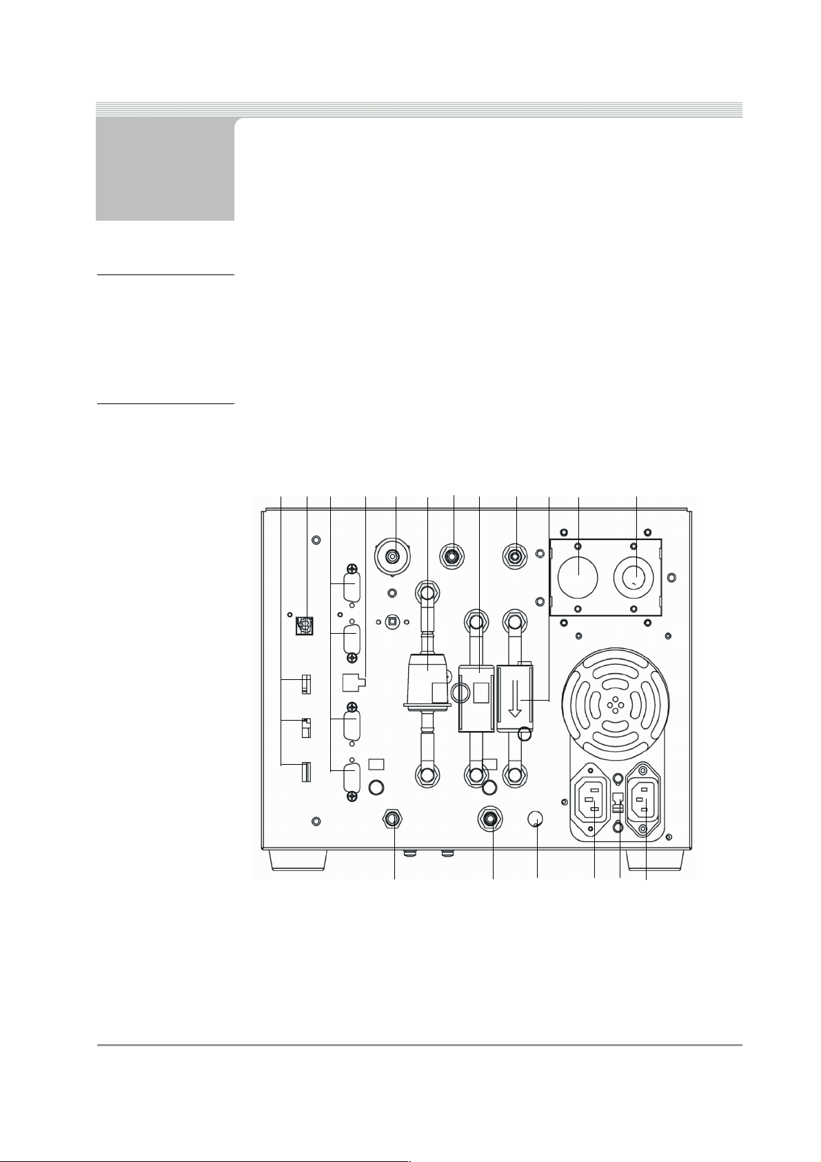
4.2 Gas Module Layout
23 4 5 67891011 12
1
18
Figure 4-1 The Gas Module - Rear Panel
1. 3 x USB connections (used for connection to ROTI module,Infa red
reciever etc)
2. USB connection for PC interface
Doc. No.: ZEEEAGB132A Operator’s Manual 15
17
13141516
Page 22

C H A P T E R 4 FUNCTIONAL DESCRIPTION
3. 4 x RS232 connections (used for connection to Smoke Module,
Portable Data Link etc)
4. DC power output (for use with future options)
5. Clean air inlet (with charcoal filter (p/n 7096E9061-99) to filter
incoming air)
6. Primary filter (p/n 7096E9062-98)
7. Calibration gas inlet (used for the supply of calibration gas to the unit)
8. Gas Filter (white, p/n 7096E9061-03)
9. Gas sample inlet (connection point for exhaust probe/sample hose
assembly)
10. Water filter (blue, IDN-8G, p/n 7096E9061-02)
11. NO sensor (Behind cover plate; optional; p/n 7096E4060-20).
2 Sensor (behind cover plate; p/n 7096E4060-31)
12. O
13. 115/230 V~ in (115/230 V~ from cabinet power distribution system)
14. Voltage selector switch (selects 115 V~ or 230 V~)
15. 115/230 V~ out (may be used as power supply for optional or other
equipment)
16. NO outlet (gas sample outlet from NO sensor)
17. Water outlet (connect a tube to this outlet to drain water from the
water removal system)
18. Gas sample outlet (outlet for gas sample from gas bench)
16 DGA 2500 2002 - 11
Page 23
COMMON PROGRAM ELEMENTS
4.3 Common Program Elements
For details of program elements that are common across the SUN®
Diagnostic Platform system, refer to the following sections of the
Diagnostic Platform Operator’s Manual:
• For details of screen elements, refer to the Diagnotstic Platform
Manual 4.2: ‘Screen Elements’.
• For details of buttons together with an illustrated guide to icons used
in common by all system modules, refer to the Diagnostic Platform
Manual 4.3: ‘Buttons’.
• For details of the use of drop-down menus, refer to the Diagnostic
Platform Manual 4.4: ‘Drop-down Menus’.
• For details of Diagnostic Platform System Screens, refer to the
Diagnostic Platform Manual 5: ‘Diagnostic Platform System Screens’.
• For details of controls and navigation, refer to the Diagnostic Platform
Manual 6.1: ‘Navigation’.
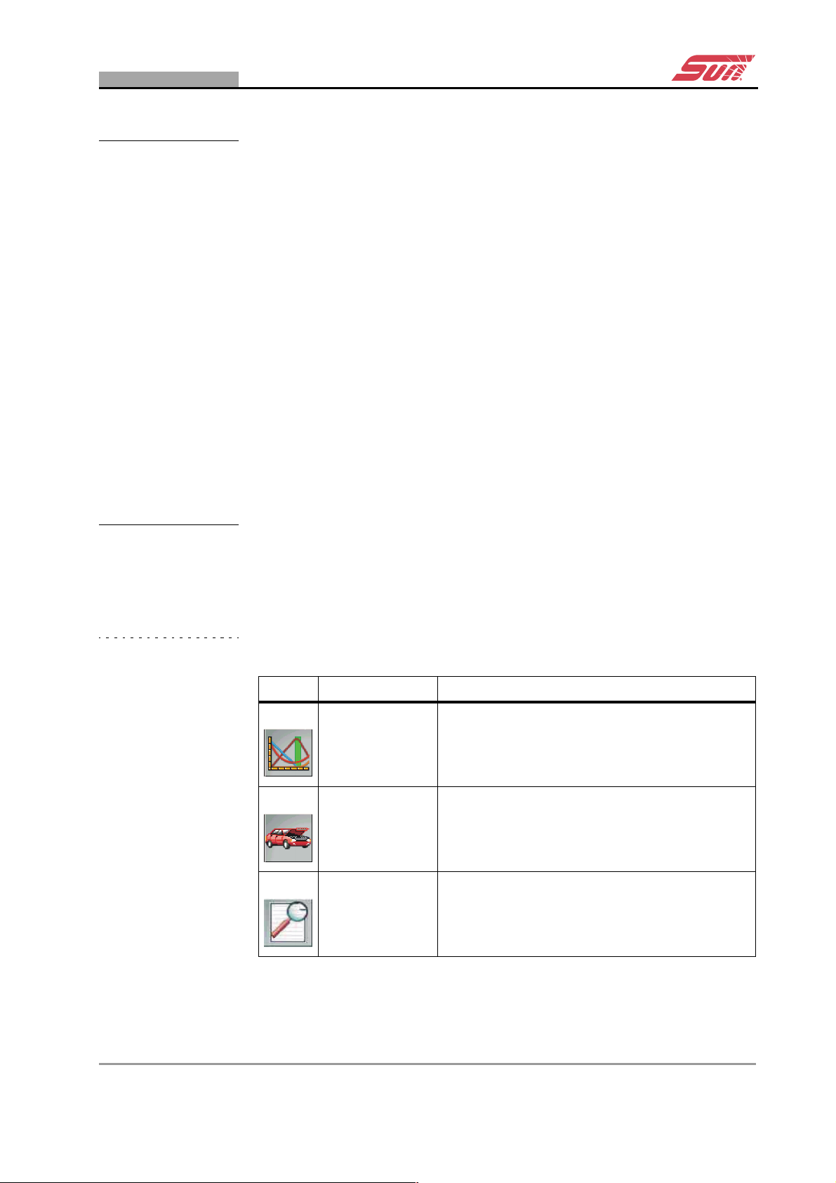
4.4 Gas Analyser Icons
The toolbar and menu icons shown in the tables are specific to the Gas
Analyser.
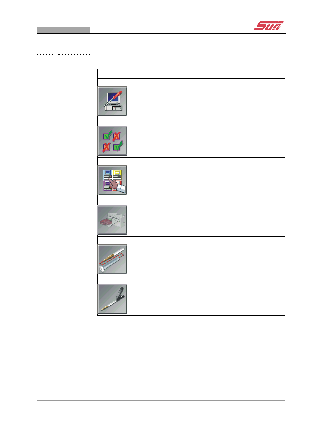
Table 4-1 Gas Analyser Toolbar Icons
Icon Name Desription
Gas Analyser
Vehicle Setup
Print Preview Use this button to preview the data to be printed.
Use this button to return to the Gas Analyser
Main Menu.
Use this button to access the vehicle setup
screens (see 8.2: ‘Free Measurement Vehicle
Setup’ and 9.2: ‘SUN EEC Test Vehicle Set-up’).
Doc. No.: ZEEEAGB132A Operator’s Manual Rev.: C 17
Page 24
C H A P T E R 4 FUNCTIONAL DESCRIPTION
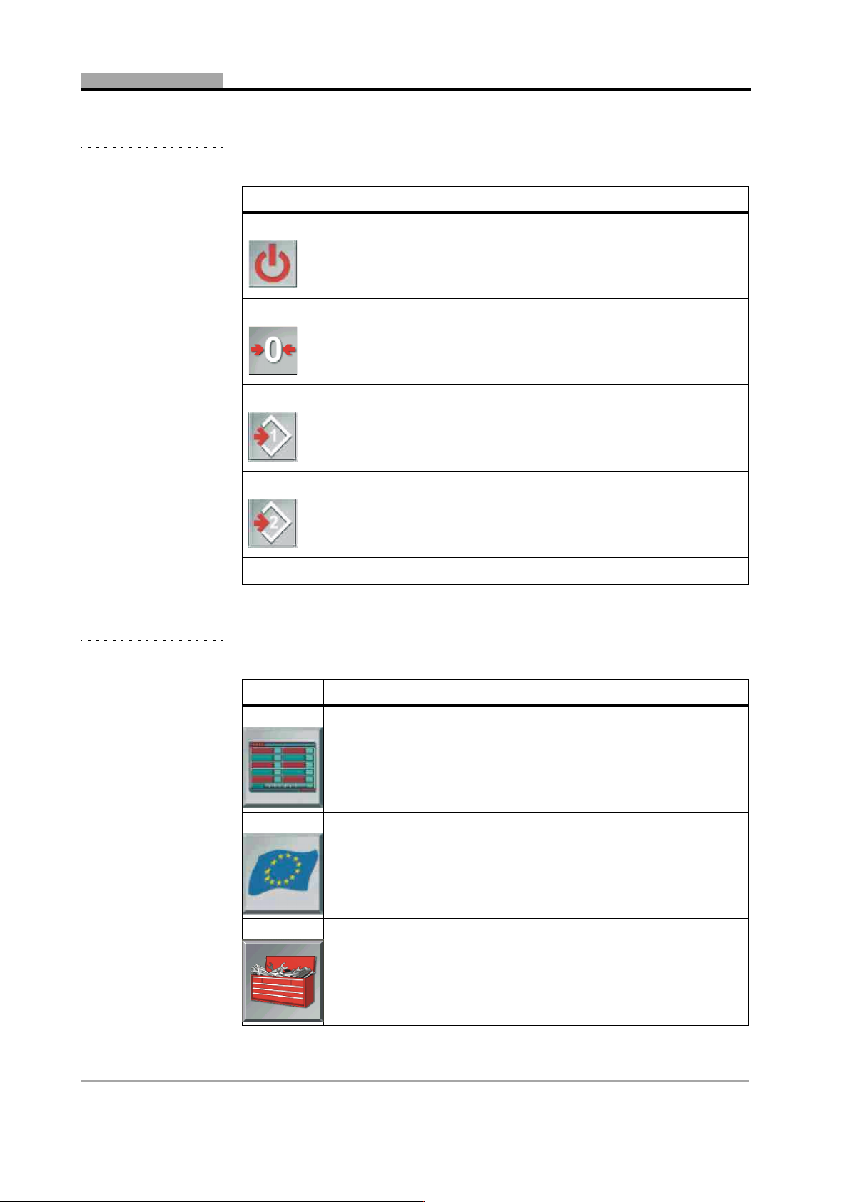
Table 4-1 Gas Analyser Toolbar Icons
Icon Name Desription
Standby
Zerocalibration
Toggle Limits 1
Toggle Limits 2
Table 4-2 Gas Analyser Menu Icons
Use this button to place the unit in standby
mode.
Use this button to manually initiate a zerocalibration (see 6.2: ‘Start-Up’).
Indicates that limit set 1 is currently applied; click
to toggle to limit set 2; (see 8.2: ‘Free
Measurement Vehicle Setup’ and 8.5: ‘Free
Measurement Test Procedure’).
Indicates that limit set 2 is currently applied: click
to toggle to limit set 1; (see 8.2: ‘Free
Measurement Vehicle Setup’ and 8.5: ‘Free
Measurement Test Procedure’).
Icon Name Description
Free
Measurement
Selects the Free Measurement Program (see
8: ‘Operation – The Free Measurement
Procedure’)
Selects the EU test procedure (see
EU
Gas Analyser
System Setup
9: ‘Operation – The SUN EEC Test
Procedure’)
1
Selects the The Gas Analyser System Menu
18 DGA 2500 2002 - 11
Page 25
GAS ANALYSER ICONS
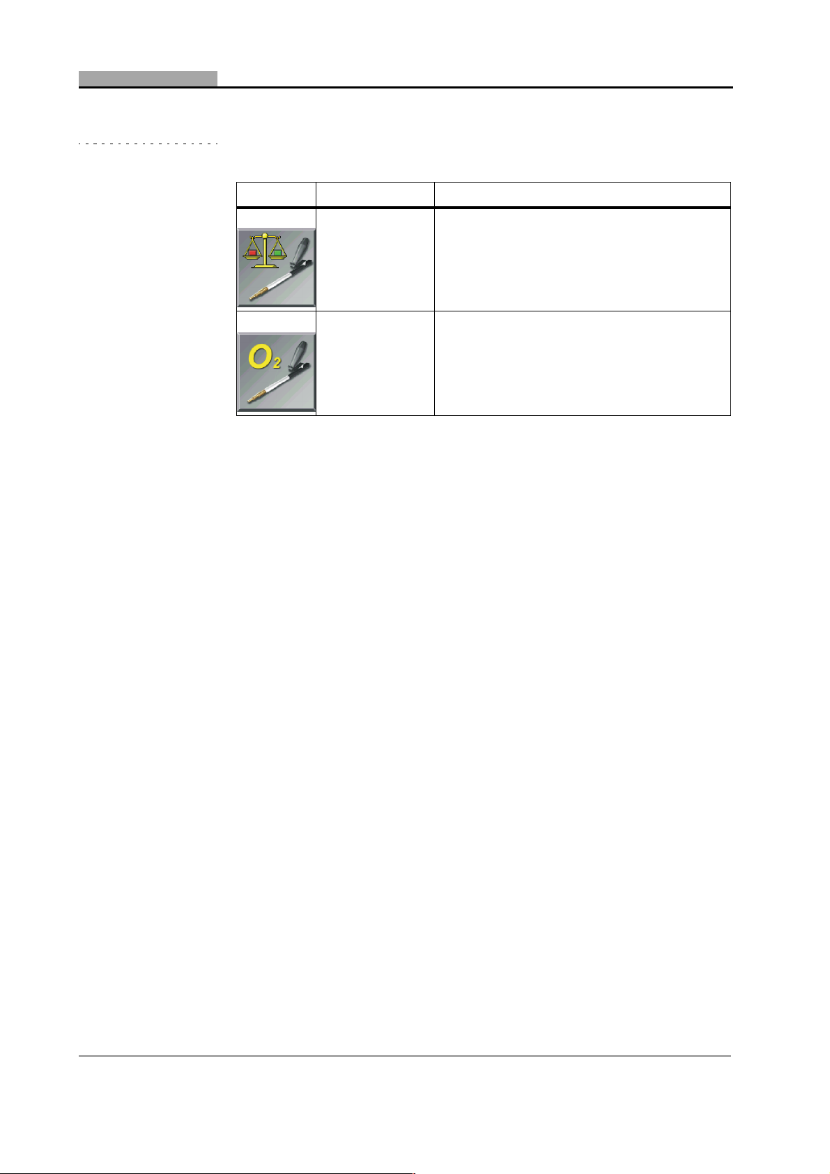
Table 4-2 Gas Analyser Menu Icons
Icon Name Description
Maintenance Selects the Gas Analyser Maintenance Menu
Setings Selects the Gas Analyser System Settings
Gas Analyser
System
Infomation
Selects Gas Analyser System Information
Gas analyser
Software
Update
Leak Check
(Vacuum)
Leak Check
(Gas)
Allows updated softwareto be loaded.
Currently disabled.
Initiates the Leak Check (Vacuum)
maintenance procedure.
Initiates the Leak Check (Gas) maintenance
procedure.
Doc. No.: ZEEEAGB132A Operator’s Manual Rev.: C 19
Page 26
C H A P T E R 4 FUNCTIONAL DESCRIPTION
Table 4-2 Gas Analyser Menu Icons
Icon Name Description
Gas Calibration
Check
Check/install
O
Cell
2
1
If a specific national test procedure is installed on the unit, the EU icon button will
be replaced by the button relating to that procedure.
Initiates the Gas Calibration Check
maintenance procedure.
Initiates the Check and/or Install the O2 Cell
maintenance procedure.
20 DGA 2500 2002 - 11
Page 27

5 System and Gas Analyser
General Screens
This Chapter contains:
• A description of the DGA 2500 Gas Analyser System Screens. Gas
Analyser System Screens are defined as being screens shown by the
DGA 2500 that do not relate to a specific test procedure. These
Screens comprise:
- The Gas Analyser Main Menu (5.1: ‘Gas Analyser Menu’).
- The Gas Analyser System Menu (5.2: ‘The Gas Analyser System
Menu’).
- The Gas Analyser Maintenance Menu (5.3: ‘Gas Analyser
Maintenance Menu’).
- The Gas Analyser System Settings Screen (5.4: ‘Gas Analyser
System Settings’).
- The Gas Analyser System Information Window (5.5: ‘Gas
Analyser System Information’).
• Details of the procedure to be followed in order to obtain a printout of
the DGA 2500 gas analysis test results (5.6: ‘Print’).
Descriptions of the SUN
System Setup screens may be found in the Diagnostic Platform
Operator’s Manual (5.1: ‘The Diagnostic Platform Main Menu’ & 5.2: ‘The
General System Setup Screen’).
® Diagnostic Platfrom Startup and General
Doc. No.: ZEEEAGB132A Operator’s Manual 21
Page 28

C H A P T E R 5 SYSTEM AND GAS ANALYSER GENERAL SCREENS
5.1 Gas Analyser Menu
.
Figure 5-1 The Gas Analyser Menu
• To access the Gas Analyser Menu , select the “Gas Analyser” option
from The Diagnostic Platform Main Menu (see the SUN
Platform Operator’s Manual 5.1: ‘The Diagnostic Platform Main
Menu’).
The following options may be selected:
- Free Measurement Procedure.
- SUN EEC Test Procedure.
- The Gas Analyser System Setup Menu.
Note:
p If the DGA 2500 is configured to perform a country specific test
procedure, the SUN EEC test procedure will not be available. In this
case the “SUN EEC Test” button will be replaced by an icon button
corresponding to the country specific test in question.
• The “Free Measurement” procedure.
The Free Measurement procedure continuously measures and
displays the values for all available test parameters. Upper and lower
limits for any or all of these parameters may be introduced as
required. Refer to 8: ‘Operation – The Free Measurement
Procedure’for further information.
® Diagnostic
• The “SUN EEC Test” procedure.
22 DGA 2500 2002 - 11
Page 29

GAS ANALYSER MENU
The SUN EEC Procedure is based on the provisions of EU directives
which specify a procedure to be followed in testing motor vehicle
emissions and prescribes maximum default values for certain gas
emissions and related parameters. Refer to 9: ‘Operation – The SUN
EEC Test Procedure’.
• The “System Setup” option.
The The Gas Analyser System Menu allows operator maintenance
functions to be initiated, gas analyser system settings to be made,
gas analyser system information to be consulted and updates to the
gas analyser software to be loaded. Refer to 5.2: ‘The Gas Analyser
System Menu’ for further information.
• To return to the The Diagnostic Platform Main Menu, press the
“Home” icon button on the toolbar.
• To place the Gas Analyser in Standby Mode, press the “Standby” icon
button on the toolbar.
Once the Gas Analyser is switched on, it should remain on for the
whole working day, however, it is recommended that the unit should
be put into Standby Mode when tests are not being performed. This
will reduce waer and tear to the pump and increase the effecive life
of the filters.
The unit will return to the normal operating mode when:
- The “Standby” button is pressed once more, or
- One of the Gas Analyser Main Menu option buttons (“Free
Measurement”, “SUN EEC Test” “Country Specific Test”, or
“System Setup”) is pressed.
On leaving the Standby Mode, a Zero-calibration (see 6.2.4) and HC
Residue Check (see 6.4) will automatically be performed before the unit
returns to normal operation.
Doc. No.: ZEEEAGB132A Operator’s Manual Rev.: C 23
Page 30
C H A P T E R 5 SYSTEM AND GAS ANALYSER GENERAL SCREENS
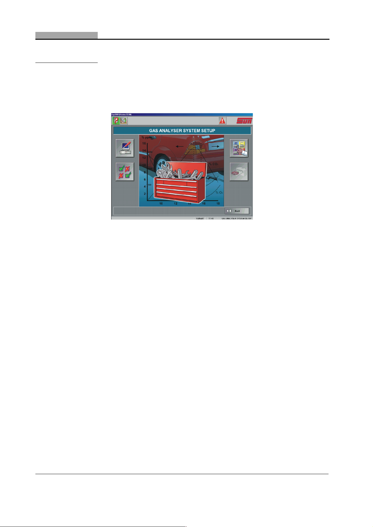
5.2 The Gas Analyser System Menu
Figure 5-2 The Gas Analyser System Menu
• To access the Gas Analyser System Menu , select the “System
Setup” option from the Gas Analyser Menu (see 5.1).
The Gas Analyser System Menu allows access to:
- The Gas Analyser Operator Maintenance Procedures.
- The Gas Analyser System Settings Screen.
- The Gas Analyser System Information Screen.
- The Gas Analyser Software Update Screen.
• To access the Gas Analyser Maintenance Menu, select the
“Maintenance” menu button.
The Gas Analyser Maintenance Menu Screen will be displayed, via
which leak checks, gas calibration checks and O
be initiated. Refer to 5.3 for a description of the Maintenance Menu
Screen and to Chapter 10: ‘Maintenance’for details of the available
maintenance procedures.
• To access the Gas Analyser System Settings Screen, select the
“System Settings” option.
The System Settings Screen allows settings to be made affecting the
operation of the gas Analyser. Refer to 5.4 for further information.
2 sensor checks can
• To reveal the Gas Analyser System Information window, select the
“System Information” option.
24 DGA 2500 2002 - 11
Page 31

GAS ANALYSER MAINTENANCE MENU
The System Information Pop-up Window provides details of gas
calibration dates, software versions etc. Refer to 5.5 for further
information.
• To access the Software Update Screen, select the “Update Software”
option.
Details of the software update procedure will be supplied with the
relevant software.
• Press “Back” or the “Gas Analyser” toolbar icon button to return to the
Gas Analyser Menu.
5.3 Gas Analyser Maintenance Menu
Figure 5-3 The Gas Analyser Maintenance Menu
• To access the Gas Analyser Maintenance Menu, select the
“Maintenance” option from the The Gas Analyser System Menu (see
5.2).
The Maintenance procedures that can be initiated from the Gas
Analyser Maintenance Menu are:
- Leak Check (Vacuum) (see 10.2).
- Leak Check (Gas) (see 10.3).
- Gas Calibration Check (see 10.4).
- Check and/or Install the O2 Cell (see 10.5).
• To initiate a Leak Check (Vacuum), select the “Leak Check (Vacuum)
option.
Doc. No.: ZEEEAGB132A Operator’s Manual Rev.: C 25
Page 32

C H A P T E R 5 SYSTEM AND GAS ANALYSER GENERAL SCREENS
• To initiate Leak Check (Gas), select the Leak Check (Gas) option.
• To initiate a Gas Calibration Check, select the Gas Calibration Check
Option.
• To Check and/or Install the O2 Cell, select the O
Option.
Details of the procedures for these checks are to be found in
10: ‘Maintenance’.
5.4 Gas Analyser System Settings
.
2 Sensor Check
Figure 5-4 The Gas Analyser System Settings Screen
To access the Gas Analyser System Settings Screen, select the “System
Settings” option from the The Gas Analyser System Menu (see 5.2).
The Gas Analyser System Settings Screen comprises drop-down menus
for the selection of:
- Lambda/AFR.
- Summertime On/Off.
- LPG composition.
• Use the “Summertime On/Off” drop-down menu to switch between
Summertime/Wintertime.
The Summertime/Wintertime information is required by the gas
module for the calculation of daily leak check and gas calibration
intervals.
26 DGA 2500 2002 - 11
Page 33

GAS ANALYSER SYSTEM SETTINGS
• Use the Lambda/AFR drop down menu to select either Lambda or Air
Fuel Ratio (AFR).
Depending on the selection, the unit will calculate and display either
Lambda or Air Fuel Ratio.
• Use the LPG Composition drop-down menu to specify the appropriate
ratio of Butane (C
test vehicle.
The available range is from 100% Butane to 100% Propane in 10%
increments. This information is required for the determination of the
ratio of Hydrogen to Carbon present in the fuel, which information is,
in turn, used for the accurate determination of Lamdba.
Note:
4H10) to Propane (C3H8) in the LPG fuel used by the
p The composition of LPG fuel may vary from country to country. If the
composition of the LPG fuel is not known, set the Butane/Propane ratio
to 50%/50%. If the composition is known (e.g. LPG used in the United
Kingdom has a composition of 0% Butane/100% Propane), this ratio
should be selected.
• Press “OK” to apply the settings made in the Gas Analyser System
Settings Screen and return to the The Gas Analyser System Menu.
• Press “Cancel” to return to the The Gas Analyser System Menu
without applying any changes made in the Gas Analyser System
Settings Screen.
• Press the “Gas Analyser” toolbar button to return to the Gas Analyser
Menu.
Doc. No.: ZEEEAGB132A Operator’s Manual Rev.: C 27
Page 34

C H A P T E R 5 SYSTEM AND GAS ANALYSER GENERAL SCREENS
5.5 Gas Analyser System Information
Figure 5-5 The Gas Analyser System Information Window
• To open the Gas Analyser System Information Window, select the
“System Information” option from the The Gas Analyser System Menu
(see 5.2).
The Gas Analyser System Information Window comprises six tabs:
- System Information (includes application versions, checksums
etc.).
- Gas Tag Values (displays the composition of the gases used for
gas calibration)
- Gas Settings (includes approval type, gas calibration interval,
summertime on/off setting, daily leak check requirement etc.).
- Service Dates (shows the last and next calibration dates, last leak
check date, date of sensor installation etc.)
- Factors (includes the applied PEF, NO gain and NO cell aging
factors).
- File Versions (Lists the version numbers of .dll and .exe files in
the DGA software)
28 DGA 2500 2002 - 11
Page 35

PRINT
5.6 Print
Figure 5-6 The “Notes” Dialog Box 1
Note:
p The DGA 2500 uses the same “Print” procedure to provide a printout of
all gas analyser test results. The following description is, therefore,
applicable irrespecive of whether the Free Measurement, SUN EEC or
Country Specific test procedure is employed.
• Open the “Notes” dialog box:
- By pressing the “Print” toolbar icon button, or
- By pressing the “Print” text button in the The Print Preview
Window (Free Measurement procedure only (see 8.7)).
The “Notes” dialog box will be displayed. The vehicle identification
information headings, entered via the “Printout Footer” box of the The
General System Setup Screen (see the Diagnostic Platform
Operator’s Manual 5.2: ‘The General System Setup Screen’), will be
shown in the left-hand text box.
• Enter the vehicle identification information for the test vehicle in the
right-hand text box, opposite the appropriate heading.
Figure 5-7 The “Notes” Dialog Box 2
• Press “OK” to make a printout of the test results.
Doc. No.: ZEEEAGB132A Operator’s Manual Rev.: C 29
Page 36

C H A P T E R 5 SYSTEM AND GAS ANALYSER GENERAL SCREENS
A typical sample results printout is illustrated below..
• Press “Cancel” to abort the print instruction and return to the test
procedure.
Note:
p Calculated values will be shown for either Lambda or AFR depending on
the setting made in the Gas Analyser System Settings Screen (see 5.4).
Note:
p Although the printout format allows all test parameters to be shown,
numerical values will only be shown for the limit values applied and test
results obtained during the current test. Fields for which no data is
available will show a series of dashes.
Figure 5-8 Sample Printout
30 DGA 2500 2002 - 11
Page 37

6 Preparatory Steps
6.1 Connections
Warning:
ä For your own and other people’s safety the DGA 2500 must only be
used in a well ventilated clean air environment
6.1.1 Power Connections
Caution:
c Before making any power connections ensure that the mains power
switch is set to “off” and that the mains voltage selector switch is
set to correspond with the local mains supply voltage.
Power is supplied to the Gas analyser from the SUN
Platform electrical distribution block via an electrical input socket located
on the rear panel of the Gas Module (see 4.2: ‘Gas Module Layout’).
6.1.2 Data Connections
Communication between the PC. Gas Module, ROTI module and infra
red Remote Control Receiver takes place via the USB (Universal Serial
Bus) connectors located on the Gas Module rear panel (see 4.2: ‘Gas
Module Layout’).
An optional USB to 4 x RS232 connector may be installed in the Gas
Module allowing for communication with optional ancillary equipment
(Smoke Meter, Portable Data Link Etc.). Connection details for such
optional ancillary equipment will be found in the relevant documentation
that will be supplied together with the equipment.
• Connect the PC USB port to the Gas module via the USB P.C.
interface connector on the Gas Module rear panel.
The P.C. interface is marked with the letter “E” on the Gas Module
rear panel.
• Connect the ROTI Module and Remote Control Receiver to the USB
connectors on the Gas Module rear panel.
® Diagnostic
Doc. No.: ZEEEAGB132A Operator’s Manual 31
Page 38

C H A P T E R 6 PREPARATORY STEPS
The USB connectors are marked with the letters “F”, “G” and “H” on
the Gas Module rear panel. Connect the ROTI Module to “G” and the
Remote Control Receiver to “F”.
Note:
p If the DGA 2500 is used in conjunction with a Portable Data Link
(Scanner), the unit will derive rpm and oil temperature data direct from
the test vehicle engine management system via the PDL. In this case the
use of the ROTI Module is unnecessary.
• Connect the Printer, Mouse and Keyboard to the P.C. Printer, Mouse
and Keyboard ports.
6.1.3 Gas Module Pneumatic Connections
• Connect the Exhaust Sample Probe and Hose to the Gas Sample
Inlet on the Gas Module rear panel.
Note:
p Do not insert the Sample Probe into the vehicle exhaust tailpipe at this
stage.
6.2 Start-Up
6.2.1 Power Up
• Set the Main, PC and Gas Module power switches to “On”.
The PC will load the Windows Operating System. After a short
interval the Windows desk-top will be displayed.
Note:
p For normal operating purposes it is recommended that the PC and Gas
Module power switches be left permanently in the “On” position and that
the unit be turned on and off with the Diagnostic Platform main power
switch.
• Select the SUN
Windows start menu or the shortcut on the desk-top.
The operating system will load the software and the The Diagnostic
Platform Main Menu will be displayed (see the Diagnostic Platform
Operator’s Manual 5.1: ‘The Diagnostic Platform Main Menu’).
• Select the Gas Analyser option from the Main Menu.
Selecting the Gas Analyser mode will display the Gas Analyser Menu
(see 5.1: ‘Gas Analyser Menu’).
® Diagnostic Platform program using either the
32 DGA 2500 2002 - 11
Page 39

START-UP
Note:
p The body of this manual concerns the operation of the DGA 2500 in Gas
Analyser mode only. Information concerning the use of the unit in
conjunction with the Diesel Smoke Meter, Portable Data Link, and
Engine Diagnostics menu options will be provided as separate
documentation.
6.2.2 Gas Analyser Start-up
At start-up, the analyser will automatically perform the following functions
in sequence:
- Warm up.
- Zero-calibration.
- HC residue check.
While these functions are being performed, “pop-up” windows will be
automatically displayed showing the status of the unit. These windows
will automatically close when the function has been successfully
completed. They may be manually closed at any time to give full access
to the screen buttons.
Note:
p A manually closed pop-up window can reappear if a new screen is
selected which requires a change in the Gas Analyser mode, e.g. a popup screen can reappear if a leak check is selected but will not reappear
when moving to a different menu or set-up screen.
If the system is configured to require a Daily Leak Check (see 6.3), the
operator will be prompted to perform this during the initial start-up
sequence.
6.2.3 Warm up
The warm-up and stabilisation period normally lasts approximately 90
seconds. During this time:
- The pump will run continuously.
- The unit will check for condensation in the gas bench.
- The warm up pop-up screen will be displayed showing the
elapsed warm up time (unless manually closed).
If the gas bench and PC are switched on simultaneously (by use of the
main power switch), the warm-up period will proceed in the background
whilst the PC loads the Windows operating system. Since the time
needed to load the operating system is greater than the warm-up period,
the latter will not be apparent to the operator. Conversely, if the gas
bench is switched on after the operating system and Diagnostic Platform
software has been loaded by the PC, the warm-up period will be visible.
Doc. No.: ZEEEAGB132A Operator’s Manual Rev.: C 33
Page 40

C H A P T E R 6 PREPARATORY STEPS
Note:
p The warm up period cannot be overridden by the operator.
At the end of the warm up period the unit will proceed to zero-calibration.
6.2.4 Zero-calibration
Zero-calibration, which allows the Gas Module to determine the correct
zero reference and gain settings, lasts approximately 30 seconds.
During this time:
- The pump will initially be off and will cut in after approximately 10
seconds.
- The zero-calibration pop-up screen will be displayed showing the
elapsed calibration time.
An zero-calibration may be triggered in three ways:
- As part of the start-up procedure or on return from standby mode
(initial zero-calibration).
- Automatically by the Gas Bench as required (automatic zerocalibration; see note below).
- Manually by the operator from The Free Measurement Screen
(see 8.1) (manual zero-calibration).
An initial or manual zero-calibration (but not an automatic zerocalibration) will be followed by a HC residue check (see below).
If the system is configured to require a Daily Leak Check, the unit will
prompt the operator to perform this at the end of the zero-calibration
period. Until a successful leak check has been preformed all
measurements will be blocked and it will not be possible to proceed
beyond the Gas Analyser Menu (see 6.3: ‘Daily Leak Check’ below for
further details).
Note:
p The gas bench automatically assesses the stability of the zero reference
and gain settings and will perform an zero-calibration as and when
required. The frequency with which an automatic zero-calibration is
performed will depend on the stability of the environment in which the
analyser is operated. If a CO
detected at the time the gas bench determines that an automatic zerocalibration is necessary, the software will assume that gas
measurements are currently being taken. In this case the zerocalibration will be delayed until the CO
0.5% vol. or for a maximum of 30 minutes. The Error/Warning toolbar
button will be displayed. If this button is pressed, error/warning code 06
will be seen, advising that a zero-calibration is pending
2 concentration of 0.5 % vol. or greater is
2 measurement has fallen below
34 DGA 2500 2002 - 11
Page 41

DAILY LEAK CHECK
Note:
p During zero-calibration the DGA 2500 derives the zero reference point
settings from the atmospheric conditions of the environment in which it is
operated. If the operating environment is poorly ventilated, or if sources
of atmospheric pollution (e.g. petrol soaked rags etc.) are present in
close proximity to the unit, this may lead to the zero reference points
being set too high. This may, in turn, lead to vehicle emission readings
that are below the zero reference settings of the analyser (“negative
indications”). To avoid this problem, the operating environment should be
well ventilated and possible sources of atmospheric pollution should be
removed.
6.3 Daily Leak Check
The accuracy of test measurements will be compromised if ambient air is
allowed to enter the analyser sampling and/or pneumatic systems. In
order to ensure the integrity of the system, the standard software
configuration requires that a leak check should be carried out prior to the
commencement of each day’s operation. The unit will not be capable of
normal operation unless a successful leak check has been carried out
within the preceding 24 hours. If the operator fails to carry out a daily
leak check, or if a leak check is failed, an error warning will appear in the
toolbar and all gas measurements will be blocked until a satisfactory leak
check has been performed.
Note:
p If the unit is left running continuously, the standard software configuration
will require a leak check to be performed within 24 hours of the previous
check. If the unit is switched off (e.g. overnight) the software will require
a leak check at the start of each operating day even if the previous leak
check was performed within the last 24 hours.
Note:
p The daily leak check requirement may be deactivated by Sun service
personnel unless the unit is configured for an approval type under which
such a check is mandatory
The leak check requirement may be satisfied by the successful
performance of either:
-A Leak Check (Vacuum) (see 10.2), or
-A Leak Check (Gas) (see 10.3).
Doc. No.: ZEEEAGB132A Operator’s Manual Rev.: C 35
Page 42

C H A P T E R 6 PREPARATORY STEPS
6.4 HC Residue Check
A HC residue check will follow every initial or manually triggered zerocalibration.
The HC residue check will be aborted or postponed if a maintenance
function is selected (e.g. in order to perform a leak check) The residue
check will be resumed when the maintenance function is exited.
The HC residue check lasts a minimum of 20 seconds with no upper
time limit. During the check the unit will:
- Display the HC Residue Check pop-up window.
- Determine the concentration of hydro-carbons present in the gas
circuit. If a concentration greater than 20 ppm is found the pop-up
window will continue to be displayed and all measurements will
be blocked until the concentration of HC present in the analyser
has fallen to within the acceptable limits.
Caution:
c The sample probe must not be allowed to remain in the vehicle
exhaust tailpipe during the HC residue check. A concentration of
more than 0.5 % vol. co
vehicle exhaust gases are being drawn into the unit. The program
will prompt the operator to remove the sample probe from the
tailpipe and all measurements will be blocked until this has been
done.
As ambient air is drawn through the gas circuit, the concentration of HC
should fall. If the residue has not fallen to within acceptable limits within
a reasonable time (1 – 2 minutes), the sample hose and probe should be
cleaned in accordance with the instructions contained in 10.6: ‘Routine
Maintenance Procedures’ and the zero-calibration procedure repeated.
If the concentration of HC does not fall to within acceptable limits after
the sample hose and probe have been cleaned the HC residue check
pop-up window will continue to be displayed. Switch the unit off and back
on in order to reset the machine. Repeat the calibration and HC residue
check procedure. If the concentration of HC is still too high, service is
required. Contact your SUN service centre or dealer.
2 detected during the check indicates that
36 DGA 2500 2002 - 11
Page 43

SETTINGS
6.5 Settings
The following settings must be made before the unit is ready for
operation:
6.5.1 Fuel Type Selection
The correct fuel type for the vehicle under test should be selected in the
Vehicle Setup screen.
• Select the vehicle fuel type (LPG, CNG or Petrol) from the fuel type
drop down menu as described in 8.2: ‘Free Measurement Vehicle
Setup’ and 9.2: ‘SUN EEC Test Vehicle Set-up’.
6.5.2 Speed Factor Setting
Refer to the SUN® Diagnostic Platform Operator’s Manual (6.2: ‘RPM
Measurement and Speed Factor Selection’) for details of factors
governing Speed Factor selection.
To set the Speed factor:
• Open the vehicle setup screen.
• Select and apply the Speed Factor as described in 8.2: ‘Free
Measurement Vehicle Setup’ or 9.2: ‘SUN EEC Test Vehicle Set-up’.
6.5.3 Lambda/AFR Selection
The DGA 2500 calculates and can display either Lambda (λ) or Air Fuel
Ratio (AFR).
To select Lambda or AFR:
• Open the Gas Analyser System Settings screen (see 5.4).
To reach the Gas Analyser System Settings screen select the
“System Settings” icon button in the Gas Analyser Menu (see 5.1).
The Gas Analyser System Menu (see 5.2) will be displayed. Select
the “Settings” Icon button in the The Gas Analyser System Menu, the
Gas Analyser System Settings page wll be shown.
• Select Lambda or AFR as required.
Doc. No.: ZEEEAGB132A Operator’s Manual Rev.: C 37
Page 44

C H A P T E R 6 PREPARATORY STEPS
6.6 Vehicle Connections
Caution:
c Route the rpm pick-up lead and oil temperature probe clear of any
hot or moving engine parts.
6.6.1 RPM Pick-Up
Refer to the SUN® Diagnostic Platform Operator’s Manual (6.2.1: ‘RPM
Pick-up (Otto Engines)’) for details of rpm pick-up connection.
6.6.2 Oil Temperature Probe
Refer to the SUN® Diagnostic Platform Operator’s Manual (6.3: ‘Oil
Temperature Measurement’) for details of oil temperature measurement.
38 DGA 2500 2002 - 11
Page 45

7 Operation — General
The following sections contain general information applicable to all test
procedures. Specific information relating to the performance of tests
using the Free Measurement Procedure and the SUN EEC Test
Procedure may be found in 8: ‘Operation – The Free Measurement
Procedure’ and 9: ‘Operation – The SUN EEC Test Procedure’
respectively.
Information necessary to conduct country specific tests (MOT, AU, APK
etc.) will be provided in separate documentation.
7.1 Testing Tips
• Read and follow the procedures in this manual.
• Keep the probe tip openings clean and free from debris.
• Do not place the probe tip in liquids or allow liquids to be drawn into
the analyser sampling system. Contamination will affect the accuracy
of any future tests.
• Do not insert the probe into an exhaust pipe until the vehicle engine is
at normal operating temperature. This allows time for the exhaust
system to vaporize any residual moisture.
• Never move the analyser by pulling on the probe, sample hose or
power cord.
• Never drive over the probe, sample hose or power cord.
• Never place any liquids on the analyser that could spill and run into
the ventilation holes.
• Clean any spilt liquids (gasoline, brake fluid, cleaning solvents etc)
from the exterior of the analyser immediately in order to protect the
finish.
• In order to ensure accurate test results, perform a daily Leak Check
(Vacuum) as described in 10.2: ‘Leak Check (Vacuum)’ below. This
check should also be performed after probe changes or filter service.
• Prolonged use of the analyser in conjunction with a dynamometer and
a hot running vehicle under load may damage the sample probe and
affect readings. An alternative sample probe (P/N: 7009-1869-00) is
available for use in these circumstances.
Doc. No.: ZEEEAGB132A Operator’s Manual 39
Page 46

C H A P T E R 7 OPERATION — GENERAL
• The O2 Sensor is stated by the manufacturer to have life expectancy
of 24 months from the date of manufacture, irrespective of how often
the analyser is used.
• The (optional) NO sensor has a minimum life expectancy of 24
months after installation or until it undergoes a 20% signal strength
loss, whichever occurs sooner. It is powered by an internal battery.
The analyser must run at least 12 hours over a 30 day period to
maintain this battery at full charge.
7.2 Measurement Procedure
Caution:
cIn order to ensure representative measurements, The engine should
be at normal operating temperature.
Note:
p Under moderate loads and operating at moderate speeds a typical
nominal oil temperature is approximately 85 °C. Under these
circumstances a temperature of 65 °C is considered to be low and a
temperature of 105 °C is considered to be high. At idling speeds engine
oil temperature does not, generally, reach a nominal value. Proper oil
temperature depends on the engine operating conditions, but may be
considered acceptable if falling within the range mentioned above.
During testing, engine exhaust gas samples are continuously gathered
by means of the Exhaust Sample Probe inserted into the vehicle’s
exhaust tail pipe.
The DGA 2500 continuouslly determines the amount of CO, CO
and O
2 present in the exhaust sample. In the Free Measuring Procedure
these values are continuously displayed in the parameter windows
together with the values for CO corrigè, engine speed and oil
temperature. If the optional NO sensor is present the value for NO will
also be measured and displayed. Depending on the selection made (see
6.5.3: ‘Lambda/AFR Selection’), the value for Lambda or Air Fuel Ratio
will also be displayed. In the SUN EEC Procedure the values measured
are displayed in the Results Screen at the conclusion of the test.
Besides determining whether or not the vehicle exhaust emissions
comply with legal requirements, emissions tests may be performed at
various engine speeds and under various conditions, forming a valuable
diagnostic aid in the discovery of a variety of engine, ignition and fuel
system service requirements.
2, HC
40 DGA 2500 2002 - 11
Page 47

SHUT DOWN PROCEDURE
After all necessary settings and connections have been made, proceed
as follows:
• Start the vehicle engine and allow the oil temperature to come up to
normal operating temperature (see Note above).
• Insert the sample probe fully into the vehicle tailpipe.
Note:
p On exhaust systems having twin tail pipes that exit a common resonator
or muffler the exhaust gas sample may be diluted by ambient air
entering the system via the tail pipe that is not in use for sampling. To
prevent this, block off the tail pipe that is not in use for the sample probe.
Note:
p Do not block off a tail pipe if the vehicle is being operated on a chassis
dynamometer. Always be sure to unblock the tail pipe when testing is
complete.
Caution:
c Do not leave the sample probe in the tail pipe when measurements
are not being made, as this will shorten the life of the filter
elements.
• When testing has been completed and the test results have been
printed or noted, remove the sample probe from the tail pipe and
store it in a dust and water free environment until it is required again.
• Remove the Oil Temperature probe from the dipstick tube and reinsert
the oil dipstick.
• Disconnect the rpm pick-up.
Caution:
c If the dipstick is of an adjustable type, ensure that it is properly
adjusted before re-inserting it into the dipstick tube.
7.3 Shut Down Procedure
Refer to the SUN® Diagnostic Platform Operator’s Manual (6.4: ‘Shut
Down Procedure’) for details of the shut down procedure.
Doc. No.: ZEEEAGB132A Operator’s Manual Rev.: C 41
Page 48

C H A P T E R 7 OPERATION — GENERAL
42 DGA 2500 2002 - 11
Page 49

8 Operation – The Free
Measurement Procedure
The Free Measurement program allows the DGA 2500 to be used as a
diagnostic tool for the investigation of the fuel, ignition and emission
control systems of a vehicle without applying the limits and procedures
specified in any local, national or international test. By operating the
vehicle under varying conditions (if neccessary on a chassis
dynanometer) it is possible to:
- Identify emission failure areas.
- Reduce emissions in general.
- Locate/correct driveability problems.
The driveability and emissions symptoms (or combinations of symptons)
that can be addressed include:
- Engine will not crank.
- Engine will crank but will not start.
- Engine is hard to start.
- Malfunction lamp is on.
- Engine stalls.
- Engine shows hesitation, sag, stumble and/or lack of power, is
sluggish or feels spongy.
- Engine surge.
- Engine misses or cuts out.
- Engine backfires.
- Excessive engine noise.
- Excessive emissions or a failed emission test.
- Poor fuel economy.
- Incorrect idle.
- Engine jumps or jerks.
- Excessive exhaust odour.
- Excessive exhaust smoke.
- Fuel odour and/or dieseling or run-on.
Doc. No.: ZEEEAGB132A Operator’s Manual 43
Page 50

C H A P T E R 8 OPERATION – THE FREE MEASUREMENT PROCEDURE
In testing emission control devices any of the following tests may be
performed as necessary, applicable or useful:
- Exhaust Gas Recirculation Valve.
- Positive Crankcase Ventilation (PCV) Valve.
-Air Pump
- Carburettor Adjustments for Vehicles Without Feedback Systems,
- Lean-misfire Adjustment.
- Lean-drop Adjustment.
- Accelerator Pump.
- Power Valve.
- High Fuel Level in Float Chamber.
- Testing the Cooling System for Combustion Gases.
- Fuel Leak.
- Exhaust Leak.
- Testing for Fumes in the Passenger Compartment.
- No-start Condition – Fuel.
The following section provides a brief description of the screens that will
be encountered during the Free Measurement Procedure
8.1 The Free Measurement Screen
Figure 8-1 The Free Measurement Screen
44 DGA 2500 2002 - 11
Page 51

THE FREE MEASUREMENT SCREEN
• To open the Free Measurement Screen, select the “Free
Measurement” option from the Gas Analyser Menu (see section 5.1).
The Free Measurement Screen displays the current values for the
test parameters that are continuously being analysed by the unit.
These values may be compared with two Limit Sets stored in the unit
memory. Limit Sets 1 and 2 are intended for use with measurements
at high and low engine speeds respectively.
Unlike the EU and country specific test procedures, available under
the DGA 2500 software, the Free Measurement Procedure does not
incorporate the requirements of any regulatory authority. The upper
and lower limits for each test parameter may be either edited by the
operator or disabled entirely.
Numerical values for the measured gas emissions, lambda/AFR, oil
temperature and engine speed are shown in the nine fields
comprising the bulk of the screen. The field background will be Green
so long as the measured value for a particular parameter falls within
the applied limits but will change to Red if the values fall outside
these limits.
An analog representation of the current test values, in relation to the
applied limits, is given by the coloured bars associated with each
parameter field. The Green section of these bars shows the range of
values falling within the limits whilst the Red sections indicate values
above and below the acceptable range. The relative proportions of
the Green and Red areas will reflect the limits applied. The value
currently measured for each parameter is represented by a thin
Yellow band.
If no limit sets are applied, or if no measurements are available, the
parameter field backgrounds and the analog bars will be Grey.
The current parameter values may be frozen, stored in the unit
memory or printed out at any time during normal operation.
• To specify the vehicle setup via the Free Measurement Vehicle Setup
Screen, press the “Vehicle Setup” toolbar button (see 8.2).
• To print test result data, press the Print button (see 5.6).
• To review or delete data stored in the data buffers, press the “Print
Preview” button to open the The Print Preview Window (see 8.7).
• To manually initiate an Zero-calibration, press the “Zero-calibration”
button (see 6.2.4).
• To toggle between limit sets, press the “Toggle Limit Sets” button (see
8.6: ‘Storing Data in the Data Buffers’).
• To freeze the current readings, press the “Freeze” button (see
8.6: ‘Storing Data in the Data Buffers’).
• To store the current readings, press the “Store” button.
Doc. No.: ZEEEAGB132A Operator’s Manual Rev.: C 45
Page 52

C H A P T E R 8 OPERATION – THE FREE MEASUREMENT PROCEDURE
The “store” button is only available after the “Freeze” button has
been pressed (see 8.6: ‘Storing Data in the Data Buffers’).
• To unfreeze the frozen readings, press the “Unfreeze” button.
The unfreeze button is only available after the “Freeze” button has
been pressed (see 8.6: ‘Storing Data in the Data Buffers’).
• To return to the Gas Analyser Menu, press the “Gas Analyser” toolbar
button.
8.2 Free Measurement Vehicle Setup
Figure 8-2 The Free Measurement Vehicle Setup Screen
To access the Free Measurement Vehicle Setup Screen, press the
“Vehicle Setup” toolbar button in the The Free Measurement Screen
(see section 8.1).
In the Free Measurement Vehicle Setup Screen it is possible to:
- Specify the vehicle fuel type.
- Save the current set-up to file.
- Load a previous set-up from file
- Load the SUN default set-up.
- Enable/disable limit sets.
- Edit limit sets.
- Enter the speed factor.
46 DGA 2500 2002 - 11
Page 53

FREE MEASUREMENT VEHICLE SETUP
The vehicle fuel type, limit set values, limit sets On/Off setting and the
speed factor are collectively refered to as the “Vehicle Setup”.
8.3: ‘Saving and Loading Vehicle Setups’ and 8.4: ‘Editing Limit Sets’
provide information on saving, loading and editing Vehicle Setups.
• Use the Fuel Type Drop-down Menu to select the correct fuel type for
the vehicle under test (see 6.5.1: ‘Fuel Type Selection’).
The available alternatives are:
- Petrol (default).
- LPG (Liquified Petroleum Gas).
- CNG (Compressed Natural Gas).
Refer to the Diagnostic Platform Operator’s Manual (4.4: ‘Drop-down
Menus’) for details of the use of drop-down menus.
Note:
p In the event of the fuel type LPG being selected, ensure that the correct
Butane/Propane ratio is entered in Gas Analyser System Settings
Screen (see 5.4). Failure to set the correct ratio may result in inaccurate
lambda calculation.
• Select the appropriate Speed Factor.
• The Speed Factor is the factor that must be applied to the raw rpm
data received by the unit (e.g. from the inductive pick-up) in order to
arrive at a true engine speed reading. For further information
concerning Speed Factor selection refer to the Diagnostic Platform
Operator’s Manual (6.2.3: ‘Speed Factor Selection’). The Speed
Factor currently applied is highlighted in green in the Speed Factor
section of the Vehicle Setup Screen. To change the applied factor:
• Click with the mouse on the desired new Speed Factor, or
• Select the new Speed Factor using the keyboard or remote control left
and right cursor keys and press the “Enter” key to confirm the new
factor.
A thin yellow frame will move along the series of Speed Factor values
as the cursor keys are pressed. When the “Enter” key is pressed the
green highlight will move to the newly selected value.
• Use the “Limits” button to enable or disable the Limit Sets.
Pressing the “Limits” button will change the status of the limit sets
from ON to OFF and vice versa. The “Limits” button will be Green
when the limits are switched ON and Red when the limits are
switched OFF.
To toggle between “Limit Sets On” and “Limit Sets Off” or vice versa:
• Click with the mouse on the “Limits” button, or
• Select the “Limits” button with the cursor keys and press “Enter”.
Doc. No.: ZEEEAGB132A Operator’s Manual Rev.: C 47
Page 54

C H A P T E R 8 OPERATION – THE FREE MEASUREMENT PROCEDURE
8.3 Saving and Loading Vehicle Setups
The vehicle setup currently displayed in the Vehicle Setup Screen can
be saved in the PC memory for future use.
The information stored will be:
-Fuel type
- Speed Factor
- Limits On/Off
- Limit set values.
To save the current vehicle setup:
• Press the “Save Setup” button.
The Save Limits File dialog box will be displayed .
Figure 8-3 The Save Limits Dialog Box
• Check the location to which the file is to be saved.
• Enter a name for the file in the File name box.
• To save the setup click “Save” or press the “Enter” key.
The file containing the vehicle setup will be saved and can be
recalled for future use using the “Load Setup” button.
• To cancel, click the “Cancel” button or press the”Esc” key.
The Save Limits File box will be closed without storing the setup.
To load a previously saved setup:
• Press the “Load Setup” button.
48 DGA 2500 2002 - 11
Page 55

EDITING LIMIT SETS
The Load Limits File dialog box will be displayed).
Figure 8-4 The Load Setup Dialog Box
• Select the file to be loaded with the mouse or enter the file name in
the file name box.
• Click “Open” in the dialog box or press the “Enter” key.
The loaded set-up will be applied in the Free Measurement Screen.
• To load the SUN default set-up, press the “Load Default” button.
• The software will warn that loading the default set-up will cause data
stored in the buffers to be lost and ask for confirmation before
continuing. Click “Yes” to proceed with loading the defaults or “No” to
continue using the current settings.
8.4 Editing Limit Sets
Figure 8-5 The Edit Limit Sets Window
Doc. No.: ZEEEAGB132A Operator’s Manual Rev.: C 49
Page 56

C H A P T E R 8 OPERATION – THE FREE MEASUREMENT PROCEDURE
To alter any or all of the limit values currently shown in the Vehicle Setup
Screen:
• Press the “Edit Limit Set” button corresponding to the Limit Set to be
edited.
The Edit Limit Set Window will be displayed.
• Use the keyboard to make the required alterations.
To alter a limit value:
• Select the value to be altered using the “Tab” key.
The selected field will be highlighted in Blue.
• Use the “Backspace” key to delete the current value.
• Enter the required new value.
• Repeat the procedure for all values that are to be altered.
• If required, repeat the procedure to edit the other limit set.
• To apply the new values, click “OK” or press the “Enter” key.
The new values will be applied and the window will be closed.
• To cancel the alterations and return to the Vehicle Setup Screen, click
“Cancel” or press the “Esc” key.
The window will be closed and the current limit values will continue to
be applied.
8.5 Free Measurement Test Procedure
Note:
p The following description of the Free Measurement Test Procedure
assumes that the Limit Sets are applied and that gas readings are
required at both high and low engine revolutions. This may not be the
case in all circumstances. Since the Free Measurement Procedure is
highly flexible and is suitable for a variety of diagnostic purposes, the
description below should be considered to be a guideline only. An
experienced operator may, for instance, consider that to perform both a
high speed and a low speed test is, in certain cases, unnecessary in
view of the diagnostic purpose of the test.
To make gas measurements using the Free Measuring procedure:
• Select the The Free Measurement Screen from the Gas Analyser
Menu (see 5.1 and 8.1).
• Make any necessary amendments to the vehicle setup in the Free
Measurement Vehicle Setup Screen (see 8.2).
• Allow the vehicle to come to normal operating temperature.
50 DGA 2500 2002 - 11
Page 57

STORING DATA IN THE DATA BUFFERS
• Insert the exhaust probe fully into the vehicle tail pipe.
Refer to the notes to 7.2: ‘Measurement Procedure’ if the test vehicle
is equipped with twin tail pipes.
• Select Limit Set 1 (see 8.1: ‘The Free Measurement Screen’)
• Accelerate the engine until the rpm reading falls within the Green
band of the Free Measurement Screen rpm indicator.
• Maintain a steady engine speed and allow the gas readings to
stabilize (approx. 30 seconds).
• Store the Limit Set 1 test results in data buffer 1 as described in
8.6: ‘Storing Data in the Data Buffers’.
After the test data for Limit Set 1 has been stored Limit Set 2 will be
automatically selected and the “Toggle Limit Sets” button will show
Limit Set 2. The Green and Red indicator bands will change to
represent the Limit Set 2 values. The fact that data is now stored in
data buffer 1 will be confirmed by the appearance of the figure “1” in
the Free Measurement Screen toolbar.
• Reduce the engine speed until the rpm indicator is between the upper
and lower limits specified for Limit Set 2, maintain a steady engine
speed and allow the gas readings to stabilize once more.
• Store the Limit Set 2 test results in data buffer 2.
After the test data for Limit Set 2 has been stored the “Toggle Limit
Sets” button will show that Limit Set 1 has been automatically
reselected and the indicator bands will change accordingly. A figure
“2” will appear in the toolbar, confirming that data is stored in data
buffer 2.
The data stored in the data buffers can be reviewed, printed or deleted
via the The Print Preview Window (see 8.7).
8.6 Storing Data in the Data Buffers
Current test readings to which a Limit Set has been applied may be
temporarily stored in one of the two data buffers. This temporary storage
allows the second Limit Set to be applied without the loss of the initial
test results. Data to which Limit Set 1 is applied will be stored in buffer 1
and data to which Limit Set 2 is applied will be stored in buffer 2.
Note:
p The following description assumes that the Free Measurement
Procedure is performed as outlined in 8.5: ‘Free Measurement Test
Procedure’ (i.e. the data to which Limit Set 1 has been applied is to be
stored before Limit Set 2 is applied). Although this will be the usual
procedure, it should be noted that it is possible to apply Limit Set 2
before Limit Set 1 or to apply either Limit Set independently.
Doc. No.: ZEEEAGB132A Operator’s Manual Rev.: C 51
Page 58

C H A P T E R 8 OPERATION – THE FREE MEASUREMENT PROCEDURE
To store data in data buffer 1:
• Apply Limit Set 1 using the “Toggle Limit Set” button .
Figure 8-6 Apply Limit Set 1
• Take the Limit Set 1 gas measurements as outlined in 8.5: ‘Free
Measurement Test Procedure’.
• Press the “Freeze” toolbar button.
Figure 8-7 Freeze Limit Set 1 Readings
The “Freeze” button will be replaced by the “Store” and “Undo”
buttons. The “Store” button will be automatically selected (indicated
by a Green background – see Figure 8-8).
• Press “Store” to store the data or “Undo” to unfreeze the data and
return to continuous measurement..
Figure 8-8 Store Limit Set 1 Readings
If the “Store” button is pressed:
- The “Store” and “Undo” buttons will be replaced by the “Freeze”
button.
- The “Freeze” button will be automatically selected.
- The number “1” (corresponding to the Limit Set and data buffer
selected) will appear in the toolbar indicating that the data is
stored in data buffer 1.
- Limit Set 2 will be applied automatically and the “Toggle Limit
Sets” button will change accordingly.
52 DGA 2500 2002 - 11
Page 59

STORING DATA IN THE DATA BUFFERS
Note:
p If the “Undo” button is pressed the “Store” and “Undo” buttons will be
replaced by the “Freeze” button. The “Freeze” button will be
automatically selected. Limit Set 1 will continue to be applied.
• Take the Limit Set 2 gas measurements as outlined in 8.5: ‘Free
Measurement Test Procedure’.
• Press the“Freeze” toolbar button.
Figure 8-9 Freeze Limit Set 2 Readings
The “Freeze” button will be replaced by the “Store” and “Undo”
buttons. The “Store” button will be automatically selected (indicated
by a Green background – see figure below).
• Press “Store” to store the Limit Set 2 data or “Undo” to unfreeze the
data and return to continuous measurement .
Figure 8-10 Store Limit Set 2 Readings
The number “2” will appear alongside the number “1” in the toolbar
indicating that data is now stored in both buffers.
Limit Set 1 will be automatically applied for the next set of
measurements and will be shown by the “Toggle Limit Sets” button.
The “Freeze” button will be automatically selected.
Figure 8-11 Limit Set 1 and 2 Readings Stored
• Press the “Print preview” button to review the stored data
Doc. No.: ZEEEAGB132A Operator’s Manual Rev.: C 53
Page 60

C H A P T E R 8 OPERATION – THE FREE MEASUREMENT PROCEDURE
8.7 The Print Preview Window
Figure 8-12 The Print Preview Window
• To open the Print Preview Window, press the “Print Preview” toolbar
button on the The Free Measurement Screen toolbar.
The Print Preview Window will be displayed. The window shows the
measurements stored in the data buffers (1 & 2) together with the
limit values applied. By using the text buttons in the Print Preview
Window it is possible to:
- Delete either or both sets of test measurements.
- Proceed to the “Print” Window.
• To delete data stored in buffer 1 (Limit Set 1), press “Delete Set 1”.
The gas measurements stored in buffer 1 will be deleted.
• To delete data stored in buffer 2 (Limit Set 2), press “Delete Set 2.
The gas measurements stored in buffer 2 will be deleted.
Note:
p Pressing the delete buttons in the Print Preview Window will only cause
the stored test data to be deleted. The limit set values will continue to be
shown and applied until either a new vehicle setup (having different limit
values) is applied or the limit sets are disabled.
• To access the Print Screen, press the “Print” button.
• To return to the The Free Measurement Screen, press the “Back”
button.
54 DGA 2500 2002 - 11
Page 61

PRINTING TEST RESULTS
8.8 Printing Test Results
Refer to 5.6: ‘Print’ for information on printing test results
Doc. No.: ZEEEAGB132A Operator’s Manual Rev.: C 55
Page 62

C H A P T E R 8 OPERATION – THE FREE MEASUREMENT PROCEDURE
56 DGA 2500 2002 - 11
Page 63

9 Operation – The SUN EEC
Test Procedure
9.1 Introduction
The Sun EEC Test Procedure allows emission testing in accordance with
EEC council directives.
The procedure described in this chapter is designed for use with vehicles
fitted with “Otto” engines (powered by petrol, liquified petroleum gas or
compressed natural gas). The procedure for testing vehicles with diesel
engines will be described in separate documentation.
For the purposes of the test procedure, vehicles are divided into three
categories:
- Vehicles fitted with a regulated catalytic converter (Catalyst Test).
- Vehicles without a catalytic converter manufactured prior to 1
October 1986 (Non-catalyst Test 1).
- Vehicles without a catalytic converter manufactured on or after 1
October 1986 (Non-catalyst Test 2).
Non-catalyst test 1 and non-catalyst test 2 differ from each other solely in
respect of the maximum permitted level of CO. Since the two noncatalyst tests procedures are, in all other ways, identical, they will be
treated as a single procedure for the purposes of this description.
When performing a SUN EEC test on vehicles fitted with a catalytic
converter, measurements will be taken at both normal and fast idle
engine revolutions. In the case of tests on vehicles without a catalytic
converter, measurements will only be taken at normal idle engine speed.
The DGA 2500 software compares the test results obtained against sets
of pre-defined limits. These limits may be either the SUN EEC default
limits (included in the program) or an alternative limit set edited and
entered by the operator. When testing catalytic converter equipped
vehicles two limit sets (one for normal idle speed and one for fast idle
speed) are applied.
Measurement parameters to which limit values are not applied will be
determined in both catalyst and non-catalyst procedures and will appear
in the Results Screen and results printout but will not affect the overall
(pass/fail) test result.
Doc. No.: ZEEEAGB132A Operator’s Manual 57
Page 64

C H A P T E R 9 OPERATION – THE SUN EEC TEST PROCEDURE
When testing catalyst equipped vehicles at fast idle, upper and lower
limits may be set for CO, HC, lambda, rpm and oil temperature. At
normal idle, limits may be set for CO, rpm and oil temperature.
In the non-catalyst test procedures, which are conducted at normal idle
speed only, limits may be set for CO, HC, rpm and oil temperature.
9.2 SUN EEC Test Vehicle Set-up
The SUN EEC Test Vehicle Set-up Screen is automatically displayed
when the SUN EEC Test Procedure option is selected in the Gas
Analyser Menu (see 5.1).
In the Vehicle Setup Screen it is possible to:
- Specify the vehicle fuel type (petrol, LPG, or CNG).
- Specify the vehicle category and test procedure (catalyst, noncatalyst 1, or non-catalyst 2).
- Save the current set-up to file.
- Load a previous set-up from file
- Load the SUN EEC default set-up.
- Edit limit sets.
- Enter the speed factor.
The vehicle fuel type, vehicle category, limit set values, and the speed
factor are collectively referred to as the “Vehicle Setup”.
9.3: ‘Editing Limit Sets’ provides information on editing Limit Set values.
9.4: ‘Saving and Loading Vehicle Set-ups’ provides information on
saving and loading Vehicle Setups.
When the EEC Test Procedure is selected the unit will automatically
carry out a zero-calibration and HC Residue check. During these checks
the Zero-calibration and HC Residue Check pop-up windows will be
displayed (see 6.2: ‘Start-Up’). These windows may be manually closed
to allow access to the Vehicle Set-up Screen but measurements will not
be possible until the zero-calibration and HC Residue checks have been
completed.
Use the Fuel Type Drop-down Menu to select the correct fuel type for the
vehicle under test.
The available alternatives are:
- Petrol (default).
- LPG (Liquefied Petroleum Gas).
- CNG (Compressed Natural Gas).
58 DGA 2500 2002 - 11
Page 65

SUN EEC TEST VEHICLE SET-UP
Refer to the Diagnostic Platform Operator’s Manual (4.4: ‘Drop-down
Menus’) for details of the use of drop-down menus.
The measurement parameter field that shows “HC” when the fuel type
”Petrol” is selected will change when the fuel type “LPG” or “CNG” is
selected and will show “LPG” or “CNG” respectively.
Note:
p In the event of the fuel type LPG being selected, ensure that the correct
Butane/Propane ratio is entered in Gas Analyser System Settings
Screen (see 5.4). Failure to set the correct ratio may result in inaccurate
lambda calculation.
• Select the appropriate vehicle category using the Vehicle Category
drop-down menu.
The selection made in the Vehicle Category menu determines which
test procedure will be used and which set of default limit values are
applicable.
The possible alternatives are:
- Vehicles equipped with a regulated catalytic converter (Catalyst
Te st )
- Vehicles without a catalytic converter, built prior to 1 October
1986 (Non-catalyst Test 1, maximum default CO limit 4.5% vol.
CO)
- Vehicles without a catalytic converter, built October 1986 or later
(Non-catalyst Test 2, maximum default CO limit 3.5% vol. CO)
The Vehicle Set-up Screen will vary depending on the vehicle category
selected. The figures below illustrate the vehicle set-up screens for both
catalyst and a non-catalyst tests.
Figure 9-1 The EEC Test Procedure Vehicle Setup Screen (Catalyst Test)
Doc. No.: ZEEEAGB132A Operator’s Manual Rev.: C 59
Page 66

C H A P T E R 9 OPERATION – THE SUN EEC TEST PROCEDURE
Figure 9-2 The EEC Test Procedure Vehicle Setup Screen (Non-catalyst Test)
• Select the appropriate Speed Factor.
The Speed Factor is the factor that must be applied to the raw rpm
data received by the unit (e.g. from the inductive pick-up) in order to
arrive at a true engine speed reading. For further information
concerning Speed Factor selection refer to the Diagnostic Platform
Operator’s Manual (6.2.3: ‘Speed Factor Selection’).
The Speed Factor currently applied is highlighted in green in the Speed
Factor section of the Vehicle Setup Screen. To change the applied
factor:
• Click with the mouse on the desired new Speed Factor or
• Select the new Speed Factor using the keyboard or remote control left
and right cursor keys and press the “Enter” key to confirm the new
factor.
A thin yellow frame will move along the series of Speed Factor values
as the cursor keys are pressed. When the “Enter” key is pressed the
green highlight will move to the newly selected value.
• Make any required amendments to the applied limit values
It is possible to:
- Edit the currently displayed limit values.
- Save the currently displayed values to file for future use.
- Load the SUN default limit values.
- Load a previously saved set of limit values.
Refer to 9.3: ‘Editing Limit Sets’ for further information.
• To initiate the test procedure, press “OK”.
60 DGA 2500 2002 - 11
Page 67

EDITING LIMIT SETS
• To abort the test procedure and return to the Gas Analyser Menu,
press “Cancel”.
9.3 Editing Limit Sets
The table below shows the parameters to which limits may be applied
within the EEC Test Procedure
Table 9-1EEC Test Procedure Limits
Catalyst Test 1 (fast
idle)
CO (% vol.) CO (% vol.) CO (% vol.)
HC (ppm vol RPM HC (ppm vol.)
Lambda RPM
RPM Oil temperature
Oil temperature
Catalyst Test 2
(Natural idle)
Non-catalyst test
Figure 9-3 The Edit Limit Set Window
To alter any or all of the limit values currently shown in the SUN EEC
Test Vehicle Set-up Screen:
• Press the “Edit Limit Set” button corresponding to the Limit Set to be
edited.
The Edit Limit Set Window for Limit Set 1 or Limit Set 2 will be
displayed.
Doc. No.: ZEEEAGB132A Operator’s Manual Rev.: C 61
Page 68

C H A P T E R 9 OPERATION – THE SUN EEC TEST PROCEDURE
Note:
p The “Edit Limit Set 2” button is only present if “Catalyst” is selected in the
Vehicle Category drop-down menu.
• Use the keyboard to make the required alterations.
To alter a limit value:
• Select the value to be altered using the “Tab” key.
- The selected field will be highlighted in Blue.
• Use the “Backspace” key to delete the current value.
• Enter the required new value.
• Repeat the procedure for all values that are to be altered.
• To accept the new values, click “OK” or press the “Enter” key.
The new values will be applied and the window will be closed. Accepted
limit values will be applied to the current test, and to all subsequent tests
using the same test procedure, until superceded. The application of a
different set of limit values will delete the values currently applied. Sets
of limit values that may be required for future tests should, therefore, be
saved to file as outlined below.
• If required, repeat the procedure to edit the other limit set.
• Press “OK” to apply the revised limits and return to the Vehicle Setup
Screen.
The window will be closed and the revisedlimit values will be applied.
• To cancel the alterations and return to the Vehicle Setup Screen, click
“Cancel” or press the “Esc” key.
The window will be closed and the current limit values will continue to
be applied.
9.4 Saving and Loading Vehicle Set-ups
The vehicle setup currently displayed in the Vehicle Setup Screen can
be saved in the PC memory for future use.
The information stored will be:
-Fuel type
- Vehicle category
- Speed factor
- Limit values.
To save the current vehicle setup:
• Press the “Save Setup” button.
62 DGA 2500 2002 - 11
Page 69

SAVING AND LOADING VEHICLE SET-UPS
The Save Limits File dialog box wiil be displayed.
Figure 9-4 The Save Limits Dialog Box
• Check the location to which the file is to be saved (C:/Program Files/
Sun Equipment/Gas Module).
• Enter a name for the file in the File name box.
• To save the setup click “Save” or press the “Enter” key.
The file containing the vehicle setup will be saved and can be
recalled for future use using the “Load Setup” button.
• To cancel, click the “Cancel” button or press the”Esc” key.
The Save Limits File box will be closed without storing the setup.
To load a previously saved setup:
• Press the “Load Setup” button.
The Load Limits File dialog box will be displayed .
Figure 9-5 The Load Limits File Dialog Box
• Select the file to be loaded with the mouse or enter the file name in
the file name box.
• Click “Open” in the dialog box or press the “Enter” key.
The loaded set-up will be applied.
• To load the SUN default set-up, press the “Load Default” button.
Doc. No.: ZEEEAGB132A Operator’s Manual Rev.: C 63
Page 70

C H A P T E R 9 OPERATION – THE SUN EEC TEST PROCEDURE
The software will warn that loading the default set-up will cause the
current limit values to be overwritten and ask for confirmation before
continuing. Click “Yes” to proceed with loading the defaults or “No” to
continue using the current settings.
9.5 Test Procedure Summary
The SUN EEC Test comprises three test procedures, each
corresponding to one of the Vehicle Categories that may be selected
using the Vehicle Category drop-down menu:
- The “Catalyst” procedure for vehicles fitted with a regulated
catalytic converter.
- The “< 10-86” procedure for vehicles without a catalytic converter
constructed prior to 1 October 1986.
- The “>= 10-86” procedure for vehicles without a catalytic
converter constructed on or after 1 October 1986.
The non-catalyst procedures vary from each other only in respect of the
maximum permitted default value for CO and will, therefore, be treated
as being identical for the purposes of this description.
The Catalyst procedure differs from the non-catalyst procedures in that:
- Measurements are taken at both fast and normal idle engine
speeds whereas, in the non-catalyst procedures, measurements
are only taken at normal idle.
- HC limits may be applied, and HC values will be displayed, at fast
idle in the Catalyst procedure and at natural idle in the noncatalyst procedure. HC limits cannot be applied, and values will
not be displayed, at natural idle in the catalyst procedure.
- Limits for lambda can only be applied, and lambda values will
only be displayed, when measuring at fast idle in the Catalyst
procedure. Lambda limits cannot be applied, and values will not
be displayed, in the Non-catalyst procedure.
Note:
p Only those measurement parameters to which limits may be applied in
each specific procedure will be displayed, however, the unit will
continuously determine and save the values for all measurable
parameters (including NO if the optional NO kit is installed). These
measured values will be displayed in the Final Results Screen and will
be included in the results printout but will not be taken into account in
determining whether or not the vehicle has passed or failed the test
procedure.
64 DGA 2500 2002 - 11
Page 71

INITIALIZATION PHASE
For convenience, the SUN EEC Test may be divided into a number of
phases which may appear in either both Catalyst and Non-catalyst
procedures or in the Catalyst procedure alone. The following list shows
these phases together with the procedures in which they appear:
1. Initialization phase (all procedures)
2. Fast idle preconditioning phase (Catalyst procedure only)
3. Fast idle measurement phase (Catalyst procedure only)
4. Normal idle preconditioning phase (all procedures)
5. Normal idle measurement phase (all procedures)
6. Results phase (all procedures)
The following sections will describe the test procedures with reference to
these phases. Where necessary, attention will be drawn to any
differences between their application in the Catalyst and Non-catalyst
procedures.
The following descriptions assume:
- That all necessary connections to the test vehicle have been
made.
- That all necessary alterations to the vehicle set-up have been
made in the Vehicle Set-up Screen.
- That the zero-calibration and HC Residue checks have been
completed.
- That the operator has pressed the “OK” button in the Vehicle Setup Screen to initiate the selected test procedure.
9.6 Initialization Phase
The Initialization Phase is identical for all SUN EEC Test procedures.
Note:
p The limit values for rpm and oil temperature that will be displayed during
the Initialization Phase will vary according to the test procedure that has
been selected in the Vehicle Set-up Screen. If a Catalyst Test is to be
performed the limit set 1 (Fast Idle) values will be shown. If a Noncatalyst Test has been selected the appropriate Normal Idle limit values
will be applied.
Doc. No.: ZEEEAGB132A Operator’s Manual Rev.: C 65
Page 72

C H A P T E R 9 OPERATION – THE SUN EEC TEST PROCEDURE
• The Initialization Screen will automatically open when the Zero-
calibration and HC residue checks have been completed and the
SUN EEC Test Vehicle Set-up Screen “OK” button has been pressed.
Figure 9-6 Initialization
• Insert the sample probe fully into the vehicle tail pipe.
During the Initialization Phase the values of all parameters will be
continuously determined but only the values for rpm and oil temperature
will be displayed.
The Initialization Screen will remain active until a concentration of 0.5%
vol. CO
pressed.
If the Catalyst Test procedure is selected the Initialization Phase will be
followed by the Fast Idle Preconditioning Phase (see 9.7).
If a Non-catalyst procedure is selected the Initialization Phase will be
followed by the Normal Idle Preconditioning Phase (see 9.9).
2 has been recorded or until the “Continue” button has been
9.7 Fast Idle Preconditioning Phase
The Fast Idle Preconditioning Phase is only encountered when
performing the Catalyst Test.
The Catalyst Test limit set 1 values will be applied during the Fast Idle
Pre-conditioning Phase.
During this phase the oil temperature and engine rpm should be brought
within the limits specified for fast idle measurement (Catalyst Test, limit
set 1).
66 DGA 2500 2002 - 11
Page 73

FAST IDLE PRECONDITIONING PHASE
The Fast Idle Preconditioning Phase consists of three screens that will
be shown in sequence.
Figure 9-7 Fast Idle Oil Temperature Check
• The Oil Temperature Check Screen will open automatically when a
concentration of 0.5% vol CO
2 is reached during the Initialization
Phase or when the “Continue” button is pressed from the Initialization
Screen.
The Screen will display the message “OIL TEMPERATURE IS
BEING CHECKED’”.
All parameters will be continuously determined. The measured
values for oil temperature and rpm will be displayed.
The screen will continue to be displayed until:
- The oil temperature reaches the minimum prescribed limit, or
- The “Continue” button is pressed.
Doc. No.: ZEEEAGB132A Operator’s Manual Rev.: C 67
Page 74

C H A P T E R 9 OPERATION – THE SUN EEC TEST PROCEDURE
• The RPM Screen will open automatically when the oil temperature
falls within the limit range or when the “Continue” button is pressed
from the Oil Temperature Check Screen.
Figure 9-8 Fast Idle Preconditioning RPM Check
The screen will show the instruction “BRING RPM WITHIN LIMITS”.
All parameters will be determined continuously and the measured values
for CO, HC, rpm and oil temperature will be displayed together with the
calculated value for lambda.
• Depress the accelerator until the engine rpm indicator is within the
Green section of the rpm scale.
The RPM Screen (Figure 9-8) will be displayed until:
- The engine speed falls within the limit range, or
- The “Continue” button is pressed.
68 DGA 2500 2002 - 11
Page 75

FAST IDLE PRECONDITIONING PHASE
• The Fast Idle Preconditioning Countdown Screen will be opened
automatically when the engine rpm falls within the limit range or when
the “Continue” button is pressed from the RPM Screen .
Figure 9-9 Fast Idle Preconditioning Countdown
The screen will show the instruction ”MAINTAIN SPEED – 60
SECONDS” together with a 60 second countdown.
Parameters will be determined and displayed as in The RPM Screen.
• Hold the accelerator depressed and maintain the engine rpm within
the fast idle range.
If, during the 60 second countdown, the engine rpm moves out of range,
the instruction on the screen will change to “BRING RPM BACK WITHIN
LIMITS”. When the rpm are once more within limits the procedure will
return to the Countdown Screen . The countdown will continue during
the time that the rpm measurement is outside the specified range.
After the first 30 seconds of the countdown, if the displayed values to
which limits are applied fall within the limit range for 2 seconds, the
values will be stored and the procedure will proceed automatically to the
Fast Idle Measurement Phase (see section 9.8).
If the values are not within limits after the whole 60 second countdown
has elapsed, the last measured values will be stored and the procedure
will move to the Fast Idle Measurement Phase.
• The operator may proceed to the Fast Idle Measurement Phase at
any time, irrespective of the measured values, by pressing the
“Continue” button.
Doc. No.: ZEEEAGB132A Operator’s Manual Rev.: C 69
Page 76

C H A P T E R 9 OPERATION – THE SUN EEC TEST PROCEDURE
9.8 Fast Idle Measurement Phase
The Fast Idle Measurement Phase is only encountered when performing
a Catalyst Test.
The Catalyst Test limit set 1 values are applied during the Fast Idle
Measurement Phase.
During the Fast Idle Measurement Phase all parameters will be
determined continuously and the measured values for CO, HC, rpm and
oil temperature will be displayed together with the calculated value for
lambda.
• The Fast Idle Measurement Phase may be entered:
- Automatically if the displayed values are within limits for 2
seconds at any time after 30 seconds of the preconditioning
phase countdown have elapsed.
- Automatically at the end of the preconditioning phase countdown
(60 seconds).
- Manually, by pressing the “Continue” button from the previous
screen.
On entering the phase the procedure will check the current status of the
engine rpm measurement.
• If the rpm value is outside the specified range, The Fast Idle
Measurement RPM Check Screen will be shown.
Figure 9-10 Fast Idle Measurement RPM Check
The screen will show the instruction “BRING RPM WITHIN LIMITS”.
70 DGA 2500 2002 - 11
Page 77

FAST IDLE MEASUREMENT PHASE
This screen will continue to be displayed so long as the engine speed
falls outside the applied limits. When the rpm measurement returns to
within the specified range Fast Idle Measurement Countdown Screen will
be displayed.
• The operator may proceed from the rpm check screen to the
countdown screen at any time, irrespective of the measured rpm
values, by pressing the “Continue” button.
• If the rpm value is within the specified range when entering the Fast
Idle Measurement Phase, The countdown screen will be shown
immediately.
Figure 9-11 Fast Idle Measurement Countdown
The screen will show the message “MAINTAIN SPEED – 120
SECONDS”.
A 120 second countdown will be displayed. If, at any time after the first
15 seconds of the countdown, the displayed values to which limits are
applied fall within the specified range for a period of 2 seconds, the
procedure will continue automatically with the Normal Idle
Preconditioning Phase.
If the values do not fall within the specified range, the full 120 second
countdown will elapse. At the end of the countdown period, the last
measured values will be saved and the procedure will continue with the
Normal Idle Preconditioning Phase.
• If the “Continue” button is pressed from the countdown screen, all
measurements will be saved and the procedure will advance to the
Normal Idle Preconditioning Phase.
Doc. No.: ZEEEAGB132A Operator’s Manual Rev.: C 71
Page 78

C H A P T E R 9 OPERATION – THE SUN EEC TEST PROCEDURE
• If the measured rpm value moves outside the specified range during
the countdown period, the Fast Idle Measurement RPM Warning
Screen will be displayed showing the message “BRING RPM BACK
WITHIN LIMITS”.
Figure 9-12 Fast Idle Measurement RPM Warning
When the rpm value has been brought within the specified range, the
countdown screen will be displayed once more. The 120 second
countdown will continue during the time that the rpm measurement is
outside the specified limits.
• The operator may return to the countdown screen from the rpm
warning screen at any time, irrespective of the measured rpm value,
by pressing the “Continue” button.
9.9 Normal Idle Preconditioning Phase
The Normal Idle Preconditioning Phase occurs in all SUN EEC test
procedures.
The Normal Idle limit values will be applied during the Normal Idle
Preconditioning Phase. The values applied will depend on the test
selected (Catalyst, Non-catalyst pre 10 – 86, or Non-catalyst post 10 –
86).
During this phase, all parameters will be continuously determined. The
measured values for CO, rpm and oil temperature will be displayed.
The Normal Idle Preconditioning Phase will be entered either
immediately after the Initialization Phase has been completed (Noncatalyst Test) or after the completion of the Fast Idle Measurement
Phase (Catalyst Test).
72 DGA 2500 2002 - 11
Page 79

NORMAL IDLE PRECONDITIONING PHASE
• On entering the Normal Idle Pre-conditioning Phase, the Normal Idle
Preconditioning RPM Check Screen will be displayed.
Figure 9-13 Normal Idle Preconditioning RPM Check
The screen will show the message “BRING RPM WITHIN LIMITS”.
• Adjust the engine speed until the rpm indicator falls within the Green
sector of the rpm scale.
The rpm check screen will continue to be displayed until:
- The rpm measurement is within the specified range, or
- The “Continue” button is pressed.
• The Normal Idle Preconditioning Countdown Screen will automatically
be shown when the rpm measurement is within the limit range or the
“Continue” button is pressed in the rpm check screen.
Figure 9-14 Normal Idle Preconditioning Countdown
Doc. No.: ZEEEAGB132A Operator’s Manual Rev.: C 73
Page 80

C H A P T E R 9 OPERATION – THE SUN EEC TEST PROCEDURE
The screen will show the instruction ”MAINTAIN SPEED – 20
SECONDS” together with a 20 second countdown.
• Hold the accelerator depressed and maintain the engine rpm within
the normal idle range.
If, during the 20 second countdown, the engine rpm moves out of range,
the instruction on the screen will change to “BRING RPM BACK WITHIN
LIMITS”. When the rpm is once more within limits the procedure will
return to the countdown screen. The countdown will continue during the
time that the rpm measurement is out of limits.
• The operator may proceed to the Normal Idle Measurement Phase at
any time, irrespective of the measured rpm value, by pressing the
“Continue” button.
The procedure will continue to the Normal Idle Measurement Phase:
- Automatically after the 20 second countdown is completed, or
- When the “Continue” button is pressed.
9.10 Normal Idle Measurement Phase
The Normal Idle Measurement Phase occurs in all SUN EEC test
procedures.
The Normal Idle limit values will be applied during the Normal Idle
Measurement Phase. The values applied will depend on the test
selected (Catalyst, Non-catalyst pre 10 – 86, or Non-catalyst post 10 –
86).
During this phase, all parameters will be continuously determined. The
measured values for CO, rpm and oil temperature will be displayed.
• The Normal Idle Measurement Phase may be entered:
- Automatically at the end of the preconditioning phase countdown
(20 seconds).
- Manually, by pressing the “Continue” button from the Normal Idle
Preconditioning Countdown Screen.
On entering the phase the procedure will check the current status of the
engine rpm measurement.
74 DGA 2500 2002 - 11
Page 81

NORMAL IDLE MEASUREMENT PHASE
• If the rpm value is outside the specified range, The Normal Idle
Measurement RPM Check Screen will be shown.
Figure 9-15 Normal Idle Measurement RPM Check
The screen will show the instruction “BRING RPM WITHIN LIMITS”.
• Adjust the engine speed until the rpm indicator falls within the Green
sector of the rpm scale.
The rpm check screen will continue to be displayed until:
- The rpm measurement is within the specified range, or
- The “Continue” button is pressed.
• The operator may proceed from The rpm check screen to the normal
idle measurement countdown screen at any time, irrespective of the
measured rpm values, by pressing the “Continue” button.
Doc. No.: ZEEEAGB132A Operator’s Manual Rev.: C 75
Page 82

C H A P T E R 9 OPERATION – THE SUN EEC TEST PROCEDURE
• If the rpm value is within the specified range when entering the
Normal Idle Measurement Phase, the countdown screen be shown
immediately.
Figure 9-16 Normal Idle Measurement Countdown
The screen will show the message “MAINTAIN SPEED – 15
SECONDS”.
A 15 second countdown will be displayed. At the end of the countdown
period, the last measured values will be saved and the procedure will
continue automatically to the Results Phase.
• If the “Continue” button is pressed from the countdown screen, all
measurements will be saved and the procedure will advance to the
Results Phase.
76 DGA 2500 2002 - 11
Page 83

NORMAL IDLE MEASUREMENT PHASE
• If the measured rpm value moves outside the specified range during
the countdown period, The Normal Idle Measurement RPM Warning
Screen will be displayed showing the message “BRING RPM BACK
WITHIN LIMITS”.
Figure 9-17 Normal Idle Measurement RPM Warning
When the rpm value has been brought within the specified range, the
countdown screen will be displayed once more. The countdown will
continue during the period that the rpm measurement is out of limits.
• The operator may return to The countdown screen from the rpm
warning screen at any time, irrespective of the measured rpm value,
by pressing the “Continue” button.
The procedure will continue to the Results Phase:
- Automatically after the 15 second countdown is completed, or
- When the “Continue” button is pressed.
Doc. No.: ZEEEAGB132A Operator’s Manual Rev.: C 77
Page 84

C H A P T E R 9 OPERATION – THE SUN EEC TEST PROCEDURE
9.11 Results Phase
The Results Phase is found in all Sun EEC test procedures.
• The Results Phase may be entered:
- Automatically at the end of the Normal Idle Measurement Phase
countdown (15 seconds).
- Manually, by pressing the “Continue” button from the Normal Idle
Countdown Screen.
- As illustrated by the figures below the results screen that will be
displayed will depend on the test conducted:If a Catalyst Test has
been performed the Results Screen will appear as illustrated by
Figure 9-18.
Figure 9-18 The EEC Catalyst Test Results Screen
78 DGA 2500 2002 - 11
Page 85

RESULTS PHASE
If a Non-catalyst Test has been performed the Results Screen will
appear as illustrated by Figure 9-19
Figure 9-19 The EEC Non-catalyst Test Results Screen
The results screens will show:
- The measured or calculated values for the various test
parameters.
- The applied limit values (where applicable).
- The overall test result (pass/fail).
- The test result for each limit set (pass/fail).
Measurement parameters for which no results were obtained and
available limit values for which no limits were specified will be
represented by a series of dashes.
Individual parameter results that are within the specified limit range will
be indicated by a Green background.
Individual parameter results that are outside the specified limits will be
indicated by a Red background.
Parameters to which no limits were applied will have a neutral (Grey)
background.
• Press the “Print” toolbar button to make a printout of the test results.
Refer to 5.6: ‘Print’ for details of the DGA 2500 print procedure.
• Press the “Vehicle Set-up” toolbar button to return to the SUN EEC
Test Vehicle Set-up Screen (see section 9.2).
The limit values applied for the current test will appear in the Vehicle Setup Screen until superceded.
Doc. No.: ZEEEAGB132A Operator’s Manual Rev.: C 79
Page 86

C H A P T E R 9 OPERATION – THE SUN EEC TEST PROCEDURE
• Press the “Gas Analyser” toolbar button to return to the Gas Analyser
Menu (see 5.1).
80 DGA 2500 2002 - 11
Page 87

10 Maintenance
The “Maintenance” section of this manual is divided into three main subsections:
- Operator initiated system checks.
- Routine maintenance procedures.
- Error codes and warnings.
10.1 System Checks
The operator may initiate the following system checks:
- Leak Check (Vacuum).
- Leak Check (Gas).
- Gas Calibration Check
- Check and/or Install the O2 Cell.
All the above checks are initiated via the Gas Analyser Maintenance
Menu (see 5.3).
10.2 Leak Check (Vacuum)
Note:
p A daily check of the gas analyser pneumatic circuit for air leaks that
could compromise the accuracy of the test results is a mandatory
requirement of many country specific test procedures (see 6.3: ‘Daily
Leak Check’). If the DGA 2500 is configured for an approval type that
requires such a daily leak check, the appropriate settings will be made at
the time of the installation of the test software. In this case the unit will
not commence normal operation unless a satisfactory leak check has
been carried out. In order to ensure the continued accuracy of the test
results, it is recommended that a daily leak check be carried out at the
start of the day’s operation even in cases where such a test is not a
statutory requirement.To conduct a Leak Check (Vacuum):
• Select the “Leak Check (Vacuum)” option from the Gas Analyser
Maintenance Menu (see 5.3)
Doc. No.: ZEEEAGB132A Operator’s Manual 81
Page 88

C H A P T E R 10 MAINTENANCE
The Leak Check (Vacuum) screen will be displayed instructing the
operator to block the sample probe inlet.
Figure 10-1 Leak Check (Vacuum) Initialization
• Block the probe inlet using the Probe Sealing Tool (p/n 7009E9317-
46) supplied with the unit.
The screen will indicate that the unit has entered a stabilisation period
during which the pump will build up a vacuum in the gas analyser
pneumatic circuit. The current vacuum will be displayed in mBar and a
status bar will indicate a 20 second countdown.
82 DGA 2500 2002 - 11
Page 89

LEAK CHECK (VACUUM)
At the end of the stabilisation period, the pump will cut out and the unit
will measure the vacuum decay over a further 20 second period. During
this measurement period the current vacuum and the vacuum decay will
be dislayed. A status bar will show a 20 second countdown.
Figure 10-2 Leak Check (Vacuum) Measurement
After the elapse of the decay measurement period the screen will
indicate either a successful or unsuccessful test result
Figure 10-3 Leak Check (Vacuum) Result
• If the leak check is successful, unblock the probe tip, store the Probe
Sealing Tool in a safe place until it is required again and press
“Continue” to return to the Gas Analyser Maintenance Menu.
Doc. No.: ZEEEAGB132A Operator’s Manual Rev.: C 83
Page 90

C H A P T E R 10 MAINTENANCE
• If the leak check is unsuccessful, check all filter and hose connections
for tightness and ensure that the sample hose is not damaged.
Repeat the Leak Check (Vacuum). Refer to 10.6.3: ‘Sample Probe
and Hose’) for information on how to isolate possible leaks in the
sampling system (Probe, Hose and Gas Filter).
• If a satisfactory result is still not obtained, and the sample hose and
connections are in order, conduct a Leak Check (Gas) (see below,
10.3: ‘Leak Check (Gas)’) to eliminate the possibility that a leak in the
gas module water circuit is influencing the result of the Leak Check
(Vacuum).
10.3 Leak Check (Gas)
The Leak Check (Gas) tests for gas/air leaks in the pneumatic system of
the gas analyser but is not influenced by leaks occuring in the gas
module water circuit. Since leaks in the water circuit do not compromise
measurement accuracy, a successful Leak Check (Gas) is considered to
fulfill the requirement for a daily leak check even if a previous Leak
Check (Vacuum) has been unsuccessful (see 6.3: ‘Daily Leak Check’).
Note:
p It will be apparent that a successful Leak Check (Gas) following an
unsuccessful Leak Check (Vacuum) indicates an internal leak in the gas
module water circuit. Although measurements will not be blocked and
normal unit operation may continue, contact your SUN dealer or Service
Representative to arrange for water circuit service.
To conduct a Leak Check (Gas):
• Select the “Leak Check (Gas)” from the Gas Analyser Maintenance
Menu (see 5.3).
84 DGA 2500 2002 - 11
Page 91

LEAK CHECK (GAS)
• The Leak Check (Gas) screen will be displayed instructing the
operator to inset the sample probe in the vehicle tail pipe and showing
the current measured level of CO
2.
Figure 10-4 Leak Check (Gas) Initialization
• Start the vehicle engine (if not already running) and insert the sample
probe fully into the exhaust tailpipe.
The unit will collect an exhaust gas sample from the vehicle and the CO
concentration will be continuously measured and displayed. When the
proper CO
2 threshold has been reached (+/- 5% vol) the screen will
indicate that a 20 second stabilisation period has begun. A status bar
representing a 20 second countdown will be shown (figure 10-5).
2
Doc. No.: ZEEEAGB132A Operator’s Manual Rev.: C 85
Page 92

C H A P T E R 10 MAINTENANCE
At the end of the stabilisation period the pump will switch off and the
screen will ask the operator to remove the probe from the tailpipe and
block the probe tip using the Probe Sealing Tool (p/n 7009E9317-46).
Figure 10-5 Leak Check (Gas) - Block Probe Tip
• Remove the sample probe from the vehicle exhaust, block the probe
tip and press the “Continue” button to proceed.
After the “Continue” button is pressed, the pump will re-start and the unit
will enter the measurement phase in which the decay in the
concentration of CO
CO
2 decay will be continuously measured and the values for CO2 and
CO
2 decay will be displayed. The status bar will show a 20 second
2 will be determined. The vacuum, CO2 level and
countdown during the decay measurement phase.
Figure 10-6 Leak Check (Gas) - Measurement
86 DGA 2500 2002 - 11
Page 93

GAS CALIBRATION CHECK
At the end of the measurement phase the screen will indicate whether
the leak check was successful or unsuccessful.
• If the leak check has been successfully performed, unblock the probe
tip, store the Probe Sealing Tool in a safe place until it is required
again and press “Continue” to return to the Gas Analyser
Maintenance Menu. If the leak check was unsuccessful, check the
sampling system for loose connections and/or damage and repeat the
test.
If the sampling sytem is in good order and the leak check is still not
satisfactory, an internal leak in the gas module is indicated. Contact your
SUN
® dealer or Service Representative.
10.4 Gas Calibration Check
The Gas Calibration check tests the calibration of the gas measurement
system against a calibration gas of a known composition. This check
should be carried out by the operator as and when necessary using a
1% accuracy gas mixture of:
- 1.3 – 1.7% vol CO
- 10.5 – 11.55 %vol CO
- 540 – 660 ppm vol HC.
Note:
2
p The Gas Calibration Check should not be confused with the full gas
calibration that should only be carried out by a SUN Service Engineer.
The DGA 2500 system may be set to specify that a full gas calibration be
performed at specified intervals (normally once every 12 months). If such
a setting has been entered into the system, the unit will give a warning
that a full gas calibration is required.
• Select the “Gas Calibration Check” option from the Gas Analyser
Maintenance Menu.
The Gas Calibration screen will be displayed holding two drop-down
menus (“Lambda calculated for” and “HC represents”) and
measurement fields for CO, CO
• Select a fuel type from the “Lambda calculated for” drop-down menu.
The alternatives (Petrol, LPG, and CNG) represent the three possible
fuel types available.
2, HC, NO, O2 and lambda.
Doc. No.: ZEEEAGB132A Operator’s Manual Rev.: C 87
Page 94

C H A P T E R 10 MAINTENANCE
• Select a gas mixture from the “HC represents” drop-down menu.
Figure 10-7 Gas Calibration Check
The available options are:
3 H8 (Propane)
-C
6 H14 (Hexane)
-C
-CH
4 (Methane)
- LPG (Liquified Pertroleun Gas).
The default setting is HC represents C
6 H14 (Hexane).
• Connect the calibration gas bottle to the calibration gas inlet on the
gas module rear panel, set the flow to 5 liters/min and turn on the gas.
• Allow the readings to stabilise and compare the readings obtained by
the analyser with the known composition of the calibration gas. The
indicated ppm vol reading for HC must be the same as the known
concentration of HC in the gas bottle.
• When the check is completed, turn off the gas and disconnect the gas
cylinder from the calibration gas inlet.
• Press “Back” to return to the Gas Analyser Maintenance Menu.
10.5 Check and/or Install the O2 Cell
The O2 cell generates an electrical voltage proportional to the O2 present
in the exhaust sample. The anlyser interprets this voltage and displays
the O
2 content as a percentage. After a zero calibration the O2
concentration should read approximately 20.93 %vol.
88 DGA 2500 2002 - 11
Page 95

CHECK AND/OR INSTALL THE O2 CELL
Due to the chemical processes within the O2 cell it has a limited life. The
current status of the cell may be derived from it’s output voltage which is
monitored by the unit software. If the output voltage falls below 7.5 mV
the unit will display a warning that the cell will soon require replacement
(“Pre-warning – change O
that cell must
O
2 cell”). The condition of the cell may be checked at any time by using
2 Check/Install facility built into the software.
the O
be changed if the output voltage drops to 7 mV (“Change
2 cell”). The unit will display an error message
To check the status of the cell:
• Select the “O
2 Check/Install” option from the Gas Analyser
Maintenance Menu.
The “O
“CHECKING O
2 Check/Install” screen will be displayed showing the message
2 CELL – PLEASE WAIT” .
Figure 10-8 O2 Sensor Status Check
• The unit will proceed to determine and display the cell output voltage
and will show the cell status as follows:
- Output voltage 7.5 mV or more – “Acceptable O
2 cell”.
- Output voltage between 7.0 mV and 7.5 mV – “Pre-warning
change O
- Output voltage less than 7.0 mV – “Change O
- Output voltage –2.5 mV – “No O
Doc. No.: ZEEEAGB132A Operator’s Manual Rev.: C 89
2 cell”.
2 cell”.
2 cell connected”.
Page 96

C H A P T E R 10 MAINTENANCE
• Press “Exit” to return to the Gas Analyser Maintenance Menu or
“Continue” to proceed with the installation of a new cell .
Figure 10-9 O2 Sensor Status Check - Result
Note:
p Once “Continue” is pressed the installation procedure must be
completed even if a new cell is not installed. If the old cell remains in situ
the software will see the existing cell as a new cell and will require that
the auto-calibration refered to below be performed.
The screen will show “Change O
“Continue” in order to proceed with the installation of a new cell.
To install a new cell:
• Remove the O
2/NO cell cover plate on the rear panel of the gas
module, remove the connector from the existing O
cell anti-clockwise to remove it.
• Install the new cell and replace the connector.
• Press “Continue”.
The unit will determine the output voltage of the new cell. If the new
cell is acceptable the screen will prompt the operator to press
“Continue” to initiate an auto-calibration.
2 cell” and ask the operator to press
2 cell and turn the
90 DGA 2500 2002 - 11
Page 97

CHECK AND/OR INSTALL THE O2 CELL
• Press “Continue” to initiate the auto-calibration .
Figure 10-10 O2 Sensor Replacement - Auto-calibration
The unit will initiate the auto-calibration and the auto-calibration pop-up
window will apppear showing the auto-calibration countdown. At the end
of the auto-calibration the screen will show the message “Installation
complete” and prompt the operator to press “Exit” to leave the
installation procedure.
• Press “Exit” to return to the Gas Analyser Maintenance screen.
• Replace the O
2/NO sensor cover plate.
Doc. No.: ZEEEAGB132A Operator’s Manual Rev.: C 91
Page 98

C H A P T E R 10 MAINTENANCE
10.6 Routine Maintenance Procedures
Caution:
c The maintenance and service procedures presented in this section
are those that the operator may perform. All other service
procedures should only be carried out by an authorised sun
service representative.
The SUN Diagnostic Gas Analyser is a precision measurement
instrument that requires little maintenance, nevertheless, the following
maintenance and service procedures should be carried out in order to
maintain the accuracy of the test results.
10.6.1 Periodic Checks
- A Leak Check (Vacuum) or a Leak Check (Gas) should be carried
out daily, before the start of operation. Refer to 10.2: ‘Leak Check
(Vacuum)’ and 10.3: ‘Leak Check (Gas)’ for further information.
- A Gas Calibration Check should be carried out as and when
required or when indicated by the system. Refer to section
10.4: ‘Gas Calibration Check’ for further information.
10.6.2 Filters
Caution:
c Failure to adequately maintain the filters will invalidate the DGA
2500 Warranty.
- CHARCOAL FILTER (p/n 7096E9061-54). The charcoal filter
should be replaced when the annual gas calibration is carried out.
- WATER FILTER (Blue, p/n 7096E9061-0). The water filter should
be replaced when it has become very dirty or clogged.
- GAS FILTER (White; p/n 7096E9061-03). The gas filter should be
replaced when the “Low Flow” warning message is displayed, or
when it has become very dirty or clogged.
- PRIMARY (PETROL) FILTER (p/n 7096E9062-98. The primary
filter should be replaced when clogged.
More frequent filter service will be required when:
- The analyser is in constant use.
- Testing vehicles not warmed up to normal operating temperature.
- Testing vehicles with very high emissions.
92 DGA 2500 2002 - 11
Page 99

ROUTINE MAINTENANCE PROCEDURES
10.6.3 Sample Probe and Hose
Periodically check the inlet holes at the probe tip for dirt and debris. To
clean:
• Disconnect the sample hose from the analyser at the sample inlet.
• Clean the probe tip using a small pointed tool or piece of thin wire.
• Blow any remaining debris away using compressed air.
Caution:
c Do not apply compressed air to the probe tip without first
disconnecting the sample hose from the sample inlet.
Backpressure could damage the sampling system.
The sample hose should be free of any cuts or abrasions that may cause
leaks. Follow the leak check procedures in this manual and replace any
damaged hoses.
Use the following test/repair procedure if the analyser fails a Leak Check
(Vacuum) or a Leak Check (Gas):
1. Ensure that assembly connections on the exhaust sample probe and
filters are tight.
a. If tight, continue with step 2.
b. If loose tighten and repeat the leak check.
c. If the analyser fails the leak check, proceed with step 2.
2. Remove the sample probe from the hose and plug the hose. Repeat
the leak check.
a. If the test fails, continue with step 3.
b. If the test is successful, install a new sample probe and repeat
the test to check for other leaks.
c. If the test still fails, continue with step 3.
3. Remove the exhaust sample hose from the inlet fitting and plug the
inlet fitting. Repeat the leak check.
a. If the test fails, proceed with step 4.
b. If the test is successful, install a new hose and repeat the leak
test to check for other leaks.
c. If the test still fails, continue with step 4.
4. Pinch off the tube connected to the gas filter with a small vise grip or
needle nose style pliers. Repeat the leak check.
Doc. No.: ZEEEAGB132A Operator’s Manual Rev.: C 93
Page 100

C H A P T E R 10 MAINTENANCE
a. If the test fails, the problem is either the hose or there is an
internal leak in the analyser. Contact your SUN Service
Representative for repair service.
b. f the test is successful, a gas filter leak is indicated. Replace the
gas filter and repeat the leak test.
c. If the test is successful, the leak is repaired.
d. If the test fails, contact your SUN Service Representative for
repair service.
10.6.4 Test Leads
- Inspect all test leads weekly for any cuts, kinks or abrasions and
replace any faulty pick-ups or leads.
- When routing leads across an engine, ensure that they do not
come into contact with any moving engine components or hot
surfaces such as exhaust manifolds etc.
- Trigger clamps should be kept free from oil, grease and other
contaminants and should be cleaned to minimise false triggering
and, therefore, false measurements.
10.6.5 O2 Cell
- The unit will indicate when the O2 cell requires replacing by
showing the “Pre-warning change O
warning messages. Refer to 10.5: ‘Check and/or Install the O2
Cell’ for further information.
10.6.6 NO Cell (Optional)
- Replace the NO cell every two years. The replacement must be
done by an authorised SUN Service Representative.
2 cell” and “Change O2 cell”
94 DGA 2500 2002 - 11
 Loading...