

Page 1

Title
Radon Monitor User’s Guide
Accurate, Reliable, Economical
Models 1028, 1029
Page 2

User’s Guide, Radon Monitor
© Copyright 2016 by Sun Nuclear Corporation. All rights reserved.
The information contained in this guide and the accompanying software program
are copyrighted and all rights are reserved by Sun Nuclear Corporation. No part
of this guide may be translated, reproduced, sold, or otherwise distributed
without the prior written consent of Sun Nuclear Corporation.
Sun Nuclear Corporation reserves the right to make periodic modifications of this
guide without obligation to notify any person or entity of such revision.
This guide is written for:
PC software: version 2.2.0
Embedded firmware: version 1.0.9
Document 1028011, Rev I, 18 August 2017
Sun Nuclear Corporation
3275 Suntree Boulevard
Melbourne, FL 32940 USA
+1 321-259-6862
www.sunnuclear.com
ii
Page 3
Preface
Description
The Continuous Radon Monitor is a detection device used to measure the
concentration of radon gas. The unit is designed for professional inspectors to
use in homes and buildings. The device is EPA verified and radon proficiency
programs approved.
CAUTION: The Continuous Radon Monitor Model 1028 is intended to be used
only for indoor applications of radon gas sampling. Using in an outdoor
environment may cause errors due to humidity and extreme temperatures.
Health and Safety Instructions
WARNING: To avoid risk of electric shock, this device must only be
connected to a supply mains with protective earth (ground).
WARNING: Never use the device in an area that could contain
explosive gases. A spark from inside the device could ignite an
explosion.
To protect Radon Monitor performance and cable insulation, never pull on a cable
to disconnect it. Always grasp the plug or connector.
Do not permit water or any other liquids to spill onto the device.
For instructions to report health or safety related concerns, see Reporting Health
or Safety Related Issues or Concerns on page 56.
iii
Page 4

Finding Additional Information
The U.S. Environmental Protection Agency (EPA) maintains a comprehensive
radon website at http://www.epa.gov/radon/index.html where you can find EPA
documents, brochures, and publications relating to radon, including:
• A Citizen's Guide to Radon: The Guide to Protecting Yourself and Your Family
from Radon. This guidance offers strategies for testing your home for radon
and discussions of what steps to take after you have tested, as well as
discussions about the risk of radon and radon myths.
• Consumer's Guide to Radon Reduction: How to Fix Your Home. This booklet
is for people who have tested their home for radon and confirmed that they
have elevated radon levels. This booklet can help with selecting a qualified
contractor to reduce the radon levels in the home, determining an appropriate radon reduction method, and maintaining a radon reduction system.
• Home Buyer's and Seller's Guide to Radon. This booklet is intended for anyone who is buying or selling a home, real estate and relocation professionals,
home inspectors and others.
iv
Page 5

Contents
Preface . . . . . . . . . . . . . . . . . . . . . . iii
Description . . . . . . . . . . . . . . . . . . . . . iii
Health and Safety Instructions . . . . . iii
Finding Additional Information . . . . . iv
Introduction . . . . . . . . . . . . . . . . . . 1
Parts . . . . . . . . . . . . . . . . . . . . . . . . . . .1
Options and Accessories . . . . . . . . .2
Connections . . . . . . . . . . . . . . . . . . . . . 3
Controls . . . . . . . . . . . . . . . . . . . . . . . .4
Standalone Operation . . . . . . . . . . 5
Position the Monitor . . . . . . . . . . . . . . 5
Install a Fresh Battery . . . . . . . . . . . . . 5
Replacing the 9V Battery . . . . . . . . . 6
Connecting the AC Adapter . . . . . . . 7
Turn on the Display . . . . . . . . . . . . . . . 7
Starting a Test . . . . . . . . . . . . . . . . . . .9
Interrupting a Test . . . . . . . . . . . . . . . .9
Displaying Average and Current . . . . 10
AVG or CUR During a Test . . . . . . .10
AVG or CUR After Test . . . . . . . . .10
Clearing Memory . . . . . . . . . . . . . . . .11
Checking Unit Status . . . . . . . . . . . . .11
Setting Up Parameters . . . . . . . . . . .12
Character Set . . . . . . . . . . . . . . . . . . .14
Display Turns Off Automatically . . . . 14
Clearing a Reset . . . . . . . . . . . . . . . . . 15
Low Battery Messages . . . . . . . . . . . 15
Low Battery with AC Power
Connected . . . . . . . . . . . . . . . . . . .15
Low Battery Without AC Power
Connected . . . . . . . . . . . . . . . . . . .16
Storage Under Power . . . . . . . . . . . . 16
Portable Printer (Optional) . . . . . 17
Printer - Parts . . . . . . . . . . . . . . . . . . .17
Printer - Description . . . . . . . . . . . . . .17
Printer Connection and Controls . . . .18
Loading the Paper . . . . . . . . . . . . . . .19
Printing a Report . . . . . . . . . . . . . . . .20
Typical Printer Report . . . . . . . . . . . .21
Movement . . . . . . . . . . . . . . . . . . .22
Printer Battery Pack . . . . . . . . . . . . . . 22
Inserting the Battery Pack . . . . . . .22
Removing the Battery Pack . . . . . .22
Charging the Battery Pack . . . . . . . 23
Low Printer Battery Indication . . . . 23
Efficient Use of Printer Battery . . .23
Printer Switch Settings . . . . . . . . . . . 24
Computer Operation . . . . . . . . . . 26
About the Software . . . . . . . . . . . . . 26
Set Up Software . . . . . . . . . . . . . . . . 26
Prerequisites . . . . . . . . . . . . . . . . . 26
Install Software . . . . . . . . . . . . . . . 26
Connecting to Computer . . . . . . . . . 27
Launch Software . . . . . . . . . . . . . . . 27
Using Software to Retrieve Data . 28
Closing Software . . . . . . . . . . . . . . . 28
About the Main Screen . . . . . . . . . . . 29
Main Screen - Inspection Tab . . . . . . 29
Main Screen - Chart Tab . . . . . . . . . . 32
Zooming In and Out . . . . . . . . . . . 33
Moving the Chart . . . . . . . . . . . . . 33
Main Screen - Pictures Tab . . . . . . . 34
Main Screen - Checklist Tab . . . . . . . 35
Menu Bar and Toolbar Functions . . . 36
Data to/from Text File . . . . . . . . . . 37
Monitor Settings Preferences . . . . . 38
Preferences Screen - Monitor
Settings Tab Details . . . . . . . . 39
Report Printing Preferences . . . . . . . 40
Preferences Screen – Print Tab
Details . . . . . . . . . . . . . . . . . . . 42
Printing Reports . . . . . . . . . . . . . . . . 44
Specifications . . . . . . . . . . . . . . . . 46
Recommended System
Requirements . . . . . . . . . . . . . . . 46
Models 1028 and 1029
Specifications . . . . . . . . . . . . . . . 46
Support and Maintenance . . . . . 48
Maintaining Hardware . . . . . . . . . . . 48
Repairs . . . . . . . . . . . . . . . . . . . . . 48
Inspection . . . . . . . . . . . . . . . . . . . 48
Storage . . . . . . . . . . . . . . . . . . . . . 48
Cleaning . . . . . . . . . . . . . . . . . . . . 48
Disposing and Recycling . . . . . . . 48
Service and Calibration . . . . . . . . . 49
Battery Life . . . . . . . . . . . . . . . . . . 49
Maintaining Software . . . . . . . . . . . . 49
Verifying Software Version . . . . . . 49
Removing Software . . . . . . . . . . . 49
Multiple Software Installations . . . 49
Optional Serial Connection . . . . . . . . 50
Serial Port Setup . . . . . . . . . . . . . . 50
v
Page 6

Connecting with a Serial Cable . . .50
Port Selection . . . . . . . . . . . . . . . .51
Radon Monitor Troubleshooting . . . .51
System Errors . . . . . . . . . . . . . . . .52
Contacting Sun Nuclear Support . . . .54
Support Website . . . . . . . . . . . . . . 54
Warranty . . . . . . . . . . . . . . . . . . . . . .54
Regulatory Supplement . . . . . . . 55
Sun Nuclear Corporation Symbols . . 55
Operator Responsibility . . . . . . . . . . 56
Reporting Health or Safety Related
Issues or Concerns . . . . . . . . . . . 56
Modifications to Equipment . . . . . . . 56
Interaction with Other Electrical
Equipment . . . . . . . . . . . . . . . . . . 56
vi
Page 7
Introduction
1
2
3
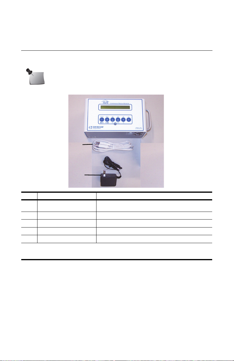
Parts
Unpack the radon monitor and identify the parts described below.
Note: Save the packing material so it can be used when sending the
radon monitor to Sun Nuclear Corporation for annual re-calibration.
No. Part Number Description
1028300 or
1
1028300-RM
801041Z Cable, USB A-B M, 2 m
2
741011** Power supply, 18 VDC, 100-240 VAC, 0.3A
3
0200014 Radon Customer Support Site letter (not shown)
—
1028012 Getting Started Guide (not shown)
—
* Model 1029 Radon Monitor is obsolete.
**Power supply P/N 741011 is only included with Model 1028 Radon Monitors shipped
within the United States.
Figure 1. Parts Furnished with Model 1028 Radon Monitor
Model 1028 Radon Monitor* or
Model 1028 Radon Monitor (Refurbished)
1
Page 8

Options and Accessories
Contact Sun Nuclear Corporation to order any of the following accessories:
Table 1. Radon Monitor Accessories
Part Number Description
1028050 Printer, thermal, 80 column, Seiko DPU-414.
022005Z Power supply for printer, 6 VDC. Used with P/N 801008Z.
750052 Rechargeable battery pack for printer (furnished with P/N 1028050 or
801008Z Line power cord for printer. Detachable, IEC Plug to USA style, 1.8 m.
801032Z Serial cable for printer, 9-pin, D-connector, M/F (furnished with
850043Z Thermal paper for printer (furnished with P/N 1028050 or can be
750004 Battery, alkaline, 9V, for radon monitor.
741011 Power converter for Radon Monitors shipped within the United States,
801041Z USB cable for Radon Monitor, 2 m.
1028012 Radon Monitor Getting Started Guide.
1028000-SC Carrying case, single radon monitor.
1028000-SPC Carrying case, single radon monitor plus printer.
1028000-DC Carrying case, dual (holds two radon monitors, printer, cables).
102378 Sign, self-adhesive, “Warning, Closed Building Procedure”.
102379 Sign, plastic, hanging, “Caution, Radon Test in Progress”.
1028130 Sign, vinyl static cling, “Warning, Closed Building Procedure”.
can be ordered separately).
P/N 1028050 or can be ordered separately).
ordered separately).
120 VAC to 12 VDC, 200 MA, 60 Hz.
2
Page 9
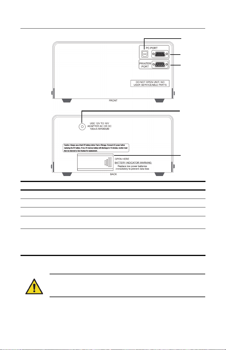
Connections
1
2
3
5
4
No Description Function
USB PC PORT (front) USB port (USB 1.1 or 2.0); for connection to a computer
1
Serial PC PORT (front) Serial port (RS-232); for connection to a computer
2
PRINTER PORT (front) Serial port (RS-232); for connection to the optional printer.
3
Power connection
4
(back)
Battery compartment
5
(back)
Power connector; connects to the power supply when
using AC power.
Insert and connect a fresh 9V battery for either backup or
primary power. A fresh alkaline battery will operate the
radon monitor for approximately 100 hours while a fresh
lithium battery will provide about 300 hours of operation.
See Replacing the 9V Battery on page 6.
Figure 2. Connections
WARNING: Always install a fresh 9V battery before test or storage
to prevent the internal 3V battery (required for operation) from
discharging.
3
Page 10
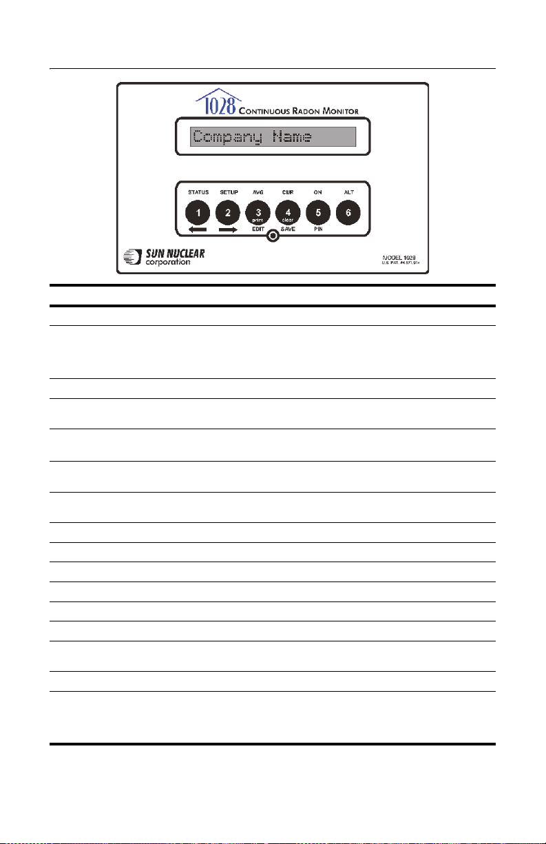
Controls
Description Function
Display 16-digit LCD display shows messages to guide the operation.
Buttons Six push buttons with different functions depending on mode. Press keys
STATUS Selects the Status mode, which scrolls through the Status settings.
SETUP Selects the Setup mode, which is used to enter setup values from the
AVG Displays the measured cumulative average radon gas concentration in pCi/l
CUR Displays the measured short-term radon gas concentration, a rolling aver-
ON Pr ess to t urn on t he d isp lay . There is n o OF F sw itch. To sav e po wer, the dis -
ALT For future use.
PIN Press to enter PIN (personal identification number), if used.
SAVE Saves the Setup mode values that were entered.
EDIT Allows editing of the Setup mode entries.
Right arrow Scrolls ahead during Setup or Status.
Left arrow Scrolls backward during Setup or Status.
Clear Clears the test memory in Print/Clear mode. Memory must be cleared
Print Sends report data to optional printer in Print/Clear mode.
Mode light The green light between EDIT and SAVE has the following meaning:
to operate. Top row of labels lists main functions. Bottom row of labels are
for Setup. Print and Clear functions are used after measurement. Numbers
are for PIN entry and Setup.
keypad.
3
or Bq/m
age of the most recent 12 hours.
play turns off automatically after a few minutes of inactivity.
before starting a new test.
• Blinks once during power up, indicating that the startup test is in prog-
• Blinks when radon is detected.
since the memory was last cleared.
ress.
Figure 3. Controls
4
Page 11
Standalone Operation
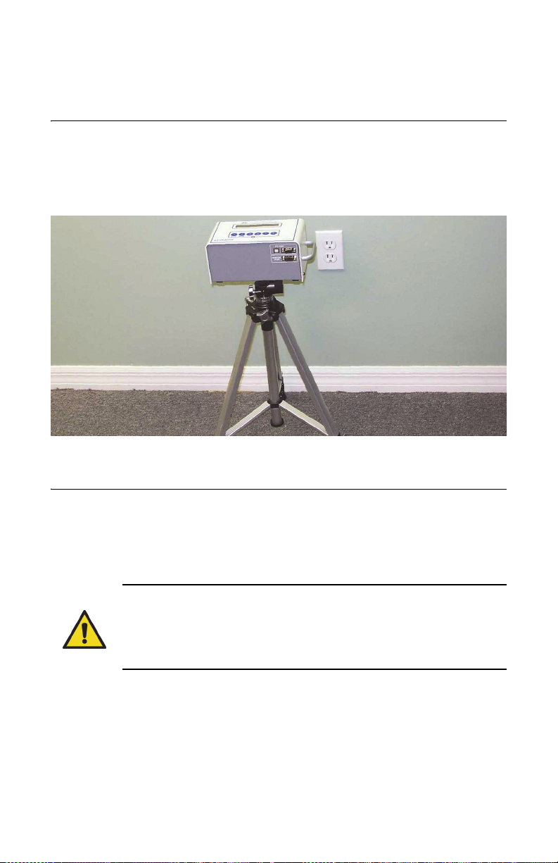
Position the Monitor
1 Place the radon monitor in the desired position in the area to be monitored
for radon gas. The radon monitor does not need to be level.
2 To use a tripod, thread the standard tripod screw (1/4-20UNC) into the
threaded fitting on the bottom of the case (Figure 4).
Figure 4. Using a Tripod
Install a Fresh Battery
The radon monitor can be operated on battery power or AC power. When
connected to AC power, the battery provides back-up power. However, even
when operating on AC power, a battery must be installed to provide backup
power.
WARNING: Always install a fresh 9V battery before test or storage,
even when the unit is connected to AC power, to prevent the internal
3V battery from discharging. The 3V battery will discharge in 15 minutes; the battery is not user-serviceable and if discharged, the unit
must be returned to Sun Nuclear for replacement.
With the radon monitor disconnected from AC power, a fresh alkaline battery will
operate the device for about 100 hours, or a fresh lithium-ion battery for about
300 hours.
5
Page 12
CAUTION: High humidity may shorten battery life. Connect the AC
power adapter when using the radon monitor in areas with high
humidity.
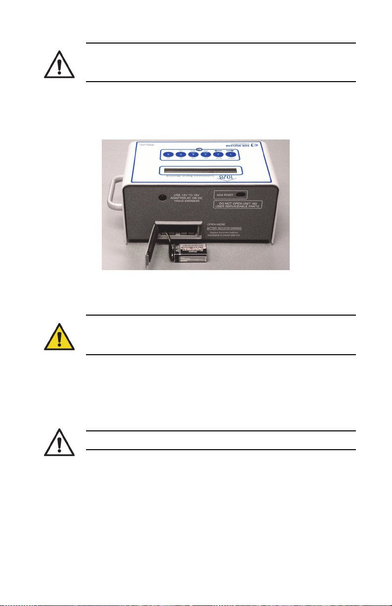
The battery is located in a small compartment on the back of the radon monitor
(Figure 5). To install a new battery, Replacing the 9V Battery, below. A replacement
9V battery can be purchased from Sun Nuclear or any retail source.
Figure 5. Inserting a Battery
Replacing the 9V Battery
WARNING: Always connect to AC power before replacing the 9V
battery, to prevent the internal 3V battery (required for operation)
from discharging.
The internal 3V battery will discharge in 15 minutes and if discharged, the unit
must be returned to Sun Nuclear for replacement. Additionally, if the 3V internal
battery is discharged, the time and date may be reset and the “Current” values
may be permanently erased.
CAUTION: Never replace the battery during a test.
1 If a test is in progress, wait for the test to complete.
2 Connect the radon monitor to AC power using the AC adapter. See
Connecting the AC Adapter on page 7.
3 Open the battery compartment door (Figure 5) on the rear panel of the unit.
4 Remove the old battery and unsnap the connector.
6
Page 13
5 Connect a fresh 9V battery to the connector, insert the battery into the
battery compartment, and close the battery compartment door.
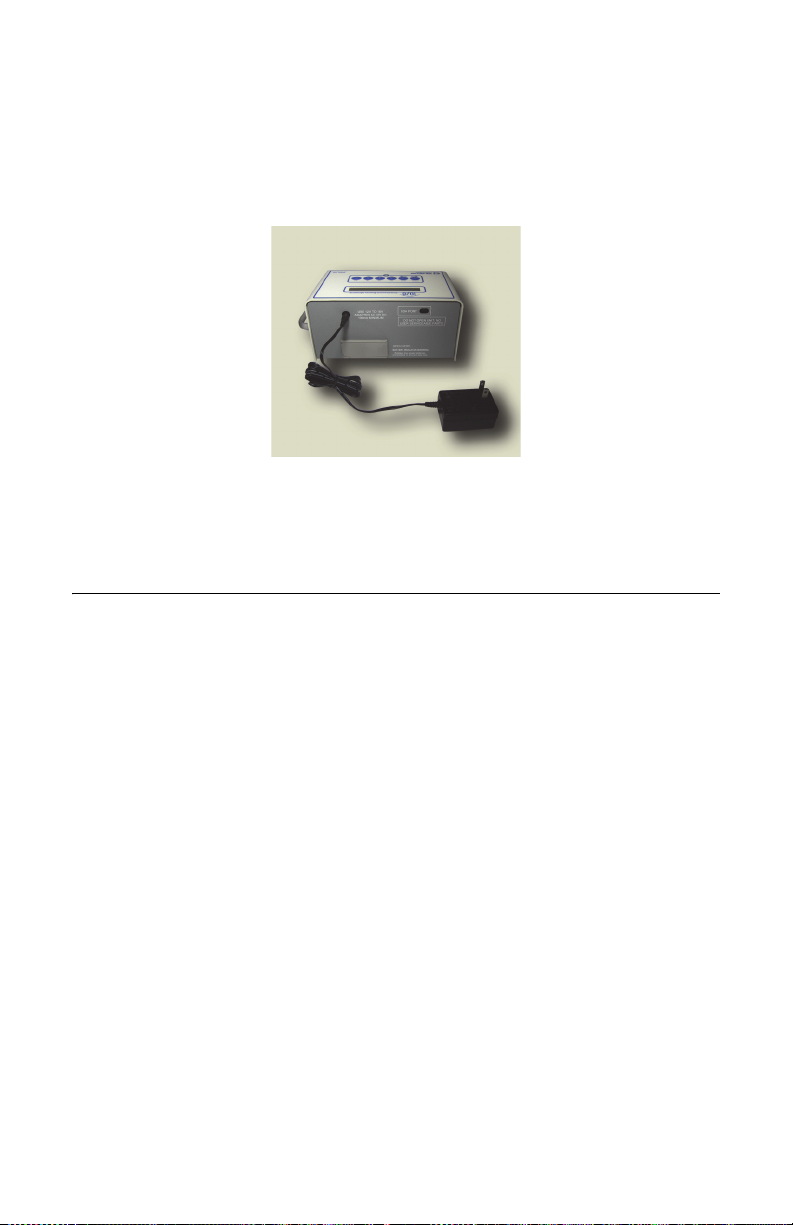
Connecting the AC Adapter
1 After verifying a battery is installed (see Figure 5 on page 6), connect the
power cable to the power connector on the rear panel of the radon monitor.
Figure 6. Connecting Power to the Radon Monitor
2 Plug one end of the power cord into the adapter and the other end into a 100
to 240 VAC, 1-phase, 50-60 Hz mains power source.
Turn on the Display
To conserve power, the 16-digit display is always off until the ON button is
pressed. If no buttons are pressed for 2 – 3 minutes, the display turns off
automatically.
To turn the display on:
1 Press the ON button (5). After a few seconds, the display turns on and shows
the message “Battery OK” (Figure 7).
2 If a Personal Identification Number (PIN) is set up, the display prompts the
user to enter it. The company name is displayed momentarily (if set up)
followed by the message “Checking Memory.” If there is data in memory, the
message “Data in Memory!” appears. The data can be printed before
clearing the memory.
7
Page 14
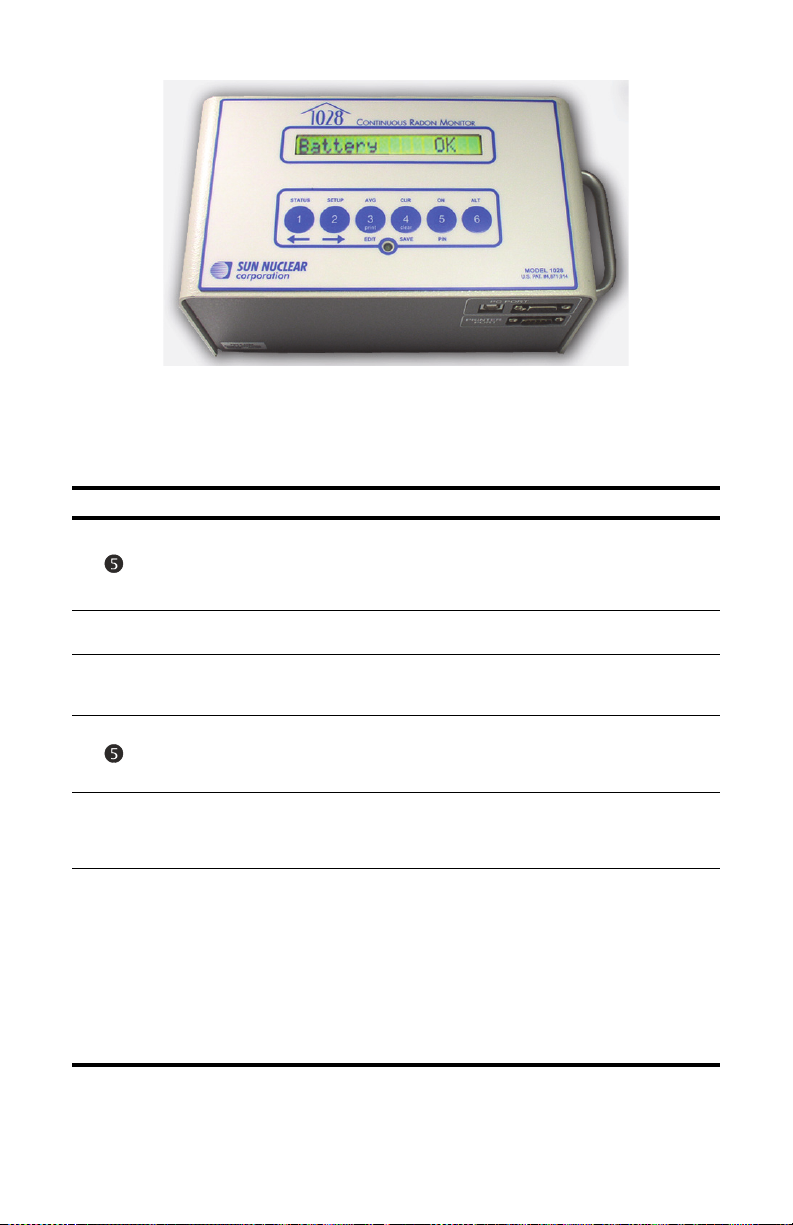
Figure 7. Turning on the Display
3 When the display shows “Start Test = 5,” the user may start a new test,
check AVG, check CUR, check STATUS, or change SETUP. The table below
summarizes the steps to turn on the display.
Press…* Display Shows… Comment
Display is always off until ON key (5) is pressed. “Battery OK” means there is enough power for 60 hours of
operation (delay plus test). “Low/No Battery!” means
that the battery has less than 60 hours operating life, or
there is no battery installed.
Only appears if a Personal Identification Number has
been set up.
Enter PIN using digits 1 – 4 (5 and 6 not supported;
there are no buttons for 7 – 9). Numbers entered are
displayed. Enter “5' after entering PIN.
Press PIN button (5). If correct PIN was entered, company name (if set up) displays. If wrong PIN was
entered, message “Shutting down...” appears briefly
and then display turns off.
If data is in memory, the messages “Data in Memory!”
and “Print and Clear” are displayed. Print and Clear the
memory before starting a new test. See Clearing Mem-
ory on page 11.
With the display reading “Start Test = 5,” the user can
press a button to:
• Start a test. See Starting a Test on page 9.
• Check AVG or CUR. See Displaying Average and Cur-
rent on page 10.
• Check STATUS. See Checking Unit Status on
page 11.
• SETUP the unit. See Setting Up Parameters on
page 12.
After a few minutes of inactivity, the display turns off
automatically to save power.
–
nnnn
–
–
Battery OK
Enter PIN
NNNN
Company Name
Checking
Memory
Start Test = 5
8
Page 15

Starting a Test
When the “Start Test = 5” prompt appears, press the 5 button to start a new test.
Press… Display Shows… Comment
–
Start Test = 5
Checking Memory
–
Delay 0 hr
–
Interval 1 hr
–
Duration 12 hr
–
Test in Progress
A new test can be started.
Memory is rechecked. If data is found, memory
must be cleared before starting a new test. See
Clearing Memory on page 11.
Displays the time delay defined in Setup.
Displays the measurement interval defined in
Setup.
Displays the test duration defined in Setup.
The test has started and will be finished after the
duration defined in Setup (plus delay). The display
turns off after a few minutes and remains off until
the test is interrupted or the display is turned on.
Interrupting a Test
A test in progress can be interrupted to view the average or current readings.
After the interruption, the test can be terminated or continued.
Press… Display Shows… Comment
Battery OK
–
Enter PIN
nnnn
NNNN
NNNN
–
End Test Y=5 N=2
Confirm Y=5 N=2
Test Complete
–
Start Test = 5
Display turns on and battery is checked.
This prompt only appears if a Personal Identification
Number was set up.
Enter the PIN using only digits 1 through 4.
PIN number is displayed. Press PIN button (5) to
check PIN. If the wrong PIN is entered, the message “Shutting down...” is displayed.
Press 5 to end a test prematurely or 2 to continue.
Pressing 2 will turn off the display and continue the
test.
Note, when this message is displayed, the user
also has the option to press AVG (3) or CUR (4) to
display the average or current readings. See AVG or
CUR During a Test, below.
Press 5 to confirm or 2 to cancel.
The test is terminated.
A new test may be started. If there is partial test
data in memory, it must be cleared before starting
a new test. See Clearing Memory on page 11.
9
Page 16
Note: A completed test cannot be interrupted. After a test is
completed, pressing ON displays the normal start sequence.
Displaying Average and Current
Note: AVG is the average radon concentration over the total
monitoring period; CUR is the average radon concentration over the
last 12-hour period.
AVG or CUR During a Test
The average (AVG) or current (CUR) radon values can be displayed during a test.
Turn ON the display (see Interrupting a Test on page 9), and note the button press
options in the table below.
Press… Display Shows… Comment
–
End Test Y=5 N=2
Hold 3&4 Prt/Clr
or
–
Average 1.2
–
Current 1.2
–
Shutting down...
When the display shows this message, press
AVG (3) or CUR (4) to access those functions.
This message only appears for a moment after
pressing 3 or 4. If the test was just started, the
message “Not Enough Data” is displayed.
If AVG (3) was pressed, radon monitor displays
the average radon concentration over the total
monitoring period.
If CUR (4) was pressed, radon monitor displays
the radon concentration in the current 12-hour
period.
After displaying AVG or CUR, monitor shuts
down to resume test.
AVG or CUR After Test
The average (AVG) and current (CUR) radon values can also be displayed after a
test is completed. Turn ON the display (see Turn on the Display on page 7), and
note the button press options in the table below.
Press… Display Shows… Comment
Start Test = 5
Hold 3&4 Prt/Clr
–
Average 1.2
Hold 3&4 Prt/Clr
Press AVG (3) or CUR (4).
This message only appears for a moment after
pressing AVG (3).
Displays the average radon concentration over
the total monitoring period.
This message only appears for a moment after
pressing CUR (4).
10
Page 17
Press… Display Shows… Comment
–
Current 1.2
–
Start Test = 5
Displays the radon concentration in the current
12-hour period.
AVG or CUR reading is complete. The data for the
test remains in memory and must be cleared
before starting a new test. See Starting a Test on
page 9.
Clearing Memory
After printing the report, clear the memory using the key press options in the
table below.
Press… Display Shows… Comment
–
Start Test = 5
Prt=3 Cl=4 Ex=5
+
Confirm Y=5 N=2
Clearing Memory
It is recommended to print a report before clearing data.
When the “Start Test = 5” message appears,
press and hold 3 and 4. Keep holding until the
“Prt=3 Cl=4 Ex=5” message appears. Press 4 to
clear (or 5 to exit).
Press 5 to confirm the clear memory command.
The memory is cleared in a few seconds.
Checking Unit Status
Before starting a new test, it is recommended to scroll through the status items
to confirm they are correct.
Press… Display Shows… Comment
–
Start Test = 5
Status Menu
–
DELAY nn hr
–
INTERVAL nn hr
–
DURATION nnn hr
–
BATTERY Ok
–
TIME nn:nn PM
–
DATE MM DD YY
–
CAL MM/DD/YYYY
–
SNC MODEL 1028
The status menu can be selected when the display
shows “Start Test = 5.”
Press the (1) button to select the status menu. The
status of each item will scroll through automatically. Each item displays for about 2 seconds.
The delay time selected.
The measurement interval selected.
The duration of the test.
Battery status.
Current time.
Current date
Date of last calibration.
Model number.
11
Page 18
Press… Display Shows… Comment
–
CODE VER nnnn
–
S/N nnnnnnnnnnn
–
Status Menu Done
Embedded code (firmware) version number.
Serial number.
End of the menu. Display returns to “Start Test =
5”.
Status items can also be displayed during a test by pressing the (1) button while
the display shows “End Test Y=5 N=2.”
Setting Up Parameters
Note: If there is any test data in the radon monitor, parameters cannot
be entered. Clear test data before changing parameters.
Parameter data can be entered using a computer or by entering the characters
with the front panel keys on the radon monitor. Using a computer is the faster of
the two methods. For instructions to enter parameter data using a computer, see
Monitor Settings Preferences on page 38. The table below shows the parameter
key press options.
Press… Display Shows… Comment
Parameters can be changed at any time before
starting a test.
Entering setup menu.
Checking memory for data.
Shows current delay settings.
Press arrow buttons to change value.
• If the monitor firmware version is 106 or higher,
the delay options are 0.0 hours,12 hours, 24
hours, or 48 hours.
• If the monitor firmware version is 105 or lower,
the delay options are 0.0 hours or 12 hours.
For the steps to check firmware version on a
standalone monitor (not connected to a computer), see Checking Unit Status on page 11. For
the steps to check the firmware version from the
computer, see Monitor Settings Preferences on
page 38. The serial number and firmware version
of the unit are displayed on the right side of the
Monitor Settings screen.
Press SAVE; saves the Delay setting and
advances to Interval.
Press arrow keys to scroll through selection of
intervals, 0.5 (model 1029 only), 11.0, 2.0, 4.0, 8.0,
12,16, 20, or 24 hours.
or
or
–
Start Test = 5
Setup Menu
–
Checking Memory
–
Delay 0.0 hr
Delay 12 hr
Interval 1.0 hr
Interval 4.0 hr
12
Page 19
Press… Display Shows… Comment
Press SAVE; saves the setting and advances to
the next item.
Press arrow keys to scroll through test duration
times: 1.0, 12, 24, 36, 48, 60, 72, 84, 96, 100, or
999 hours.
If 999 is selected, measures until memory is full or
to 720 data points, whichever occurs first.
Press SAVE; saves the setting and advances to
the next.
The EDIT key (3) lets you begin to edit the first
character.
Press the arrow keys to scroll through the available characters. See Character Set on page 14 for
a list of characters. Press and hold for rapid scroll.
Press EDIT key (3) and scroll to the next and subsequent characters. Press EDIT (3) again to enter
the next character. Continue character by character until the company name is entered (up to 30
characters).
Press SAVE (4); saves the setting and advances to
the next item.
The EDIT key (3) allows editing beginning with the
first character. Enter up to 30 characters for the
first address line using the same procedure as for
Company name.
Press SAVE (4); saves the setting and advances to
the next item.
If a second address line is not needed, leave it
blank. The EDIT key (3) will allow editing beginning with the first character. Enter up to 30
characters for the second address line using the
same procedure as for Company name.
Press SAVE (4); saves the setting and advances to
the next item.
Enter city (20 characters) and SAVE (4) (same as
above).
Enter state (10 characters) and SAVE (4) (same as
above).
Enter zip code (10 characters) and SAVE (4) (same
as above).
Enter phone number (20 characters) and SAVE (4)
(same as above).
Enter license number (10 characters) and SAVE (4)
(same as above).
Enter current time (4 numbers plus AM or PM)
and SAVE (4) (same as above).
Enter current date in the format MMDDYY (6
numbers) and SAVE (4) (same as above).
or
or
and
and
and
and
and
and
and
Duration 1.0 hr
Duration 48 hr
COMPANY Company
COMPANY Company
COMPANY Mompany
COMPANY My Comp
ADDRESS1 none
ADDRESS1 9one
ADDRESS2 none
ADDRESS2 none
City none
City none
STATE none
ZIPCODE
PHONE
LICENSE
TIME
DATE
13
Page 20

Press… Display Shows… Comment
and
and
UNITS pC/l
PIN NUM 1111
Setup Menu Done
To enter parameter data using the front panel keys on the radon monitor:
1 Turn on unit.
2 Press “Setup” (button 2).
3 Advance through the list by pressing “Save” (4).
4 Stop on an item to change it.
5 Press “Edit” (3) to edit the item.
6 Press the arrow keys to scroll through a list of available characters and stop
when the desired character appears. Press and hold arrow key for fast scroll.
7 When a desired character to change appears, press “Edit” (3) again to
change it.
8 When all the characters are changed, press “Edit” to complete the item.
9 Press “Save” and advance to the next item.
Select units, pCi/l or Bq/m3 (edit, select with
arrows, and SAVE (4)).
Enter a PIN number if desired in the range of 1111
to 4444 and SAVE. The number 1111 is equivalent
to no PIN. To clear a PIN, enter 1111.
End of setup menu.
Character Set
The available character set includes the following in the sequence shown:
(space) ! “ # $ % & ‘ ( ) * + , - . / 0 1 2 3 4 5 6 7 8 9 : ; < = > ? @ A B C D E
F G H I J K L M N O P Q R S T U V W X Y Z [ \ ] ^ _ ‘ a b c d e f g h i j k l m n
o p q r s t u b w x y z
Display Turns Off Automatically
The display turns off automatically after a period of inactivity of about 2-3
minutes. There is no OFF switch or key sequence.
14
Page 21

Clearing a Reset
1 Turn on the radon monitor to check the battery. If the system is accidentally
reset, clear the reset as shown in the table below.
Press… Display Shows… Comment
Battery OK
–
System has reset
–
Check Date/Time
Clear Reset? Y=5
–
Shutting down...
Battery is checked.
System has been reset.
An alert to check the date and time and re-enter
them.
Sets the system back to operational mode.
System shuts down.
2 Start the radon monitor again. See Turn on the Display on page 7.
3 In Setup, change the date and time. See Setting Up Parameters on page 12.
Note: A reset does not clear or change any test data stored in memory.
Low Battery Messages
A 9V battery must always be installed, even when using an AC power supply, to
prevent discharge of the internal 3V battery. When the battery is low or needs to
be replaced, a message is displayed on the radon monitor. The following sections
describe the messages that may be displayed.
Low Battery with AC Power Connected
If the battery is low and the AC power adapter is connected, a message appears
when key 5 is pressed.
Press… Display Shows… Comment
Low/No Battery!
–
Replace Battery!
–
Shutting down...
Battery is checked. Does not have enough power
for a 60-hour test.
Replace the 9V alkaline battery as soon as convenient. Current test can continue until complete if AC
power is reliable.
The system shuts down to save power.
Replace the 9V battery as soon as the test is complete. See Replacing the 9V
Battery on page 6.
15
Page 22

Low Battery Without AC Power Connected
If the battery is low and the AC power adapter is not connected, a message
appears when attempting to power on.
Press… Display Shows… Comment
Low Battery!
–
No Extern. Power
–
Shutting down...
Connect the AC adapter to continue the test or perform any other operation.
Replace the 9V battery as soon as possible. See Replacing the 9V Battery on
page 6.
Battery is checked. Does not have enough power
for a 60-hour test.
Indicates AC power should be connected to continue the test in progress. At the conclusion of the
test, replace the battery.
The display shuts down to save power.
Storage Under Power
WARNING: For long term storage, always connect to AC power or
install a fresh 9V battery to prevent the internal 3V battery (required
for operation) from discharging. The 3V battery is not user-serviceable and if discharged, the device must be returned to Sun Nuclear
for replacement.
The radon monitor must always be stored with a 9V battery installed or connected
to AC power. This additional power is required to prevent discharge of the 3V
lithium battery located inside the unit. The 3V battery will discharge in 15 minutes,
and if the internal battery is discharged, it must be replaced at the factory. See
Contacting Sun Nuclear Support on page 54.
16
Page 23

Portable Printer (Optional)
Printer - Parts
The following parts are included with the optional portable printer, P/N 1028050.
Part Number Description
022005Z Power supply, 6 VDC out, 2.1 mm plug
750052 Rechargeable battery pack, 4.8 V Ni-MH
801008Z Line power cord for printer, detachable, IEC Plug to USA style,
801032Z Cable, RS-232 (serial), DB9M to DB9F, 6 ft.
850040Z Thermal printer
850043Z Thermal printer paper (roll)
Printer - Description
The optional portable printer prints reports directly from the radon monitor. It can
be connected to AC power or used as a portable printer by switching to battery
power. See Printer Battery Pack on page 22.
125 V, 10 A, 2.3 m.
Figure 8. Optional Portable Printer
The printer is not used to print reports from the computer. For computer reports,
see Printing Reports on page 44.
17
Page 24

Printer Connection and Controls
Power LED
Power switch
ONLINE/OFFLINE
button
ONLINE/OFFLINE
indicator LEDs
FEED paper
button
1 Connect the printer cable to the PRINTER PORT on the radon monitor and
the serial port on the printer’s rear panel (Figure 9).
Figure 9. Connecting the Printer Cable
2 To operate the printer on AC power, plug the power supply (P/N 022005Z)
into the power connector at the back of the printer. Then, plug the
detachable power cord (P/N 801008Z) into the power supply and into a
power source that matches the ratings on the power supply.
Alternately, the printer can be operated from the rechargeable battery.
3 Slide the Power switch (on the side of the printer) to the On (I) position.
Figure 10. Printer Controls
The Power LED (green) will illuminate and blink once every second. If the
rechargeable battery pack is low, the Power LED will blink once every 1/2
second.
18
Page 25

4 To feed paper, press the ONLINE/OFFLINE button to select off line mode
(red LED illuminated), then press the FEED button. It is only possible to feed
paper when the printer is OFFLINE.
5 When complete, press the ONLINE/OFFLINE button to select on line mode
(green LED illuminated).
• The green ONLINE LED will blink if there is data in the buffer memory
when you toggle the switch to off line mode.
• The red OFFLINE light indicates the printer is off line.
• The red OFFLINE light flashes if the paper is not set or has run out.
• Both the ONLINE and OFFLINE lights flash if there is an error.
CAUTION: Do not press and hold the ONLINE/OFFLINE button and the
FEED button simultaneously for 30 seconds or more. This resets the
printer’s internal switches and prevents use of the printer.
Loading the Paper
Note: Load the paper in an area protected from direct sunlight.
1 Unwrap the roll of thermal paper (P/N 850043Z) and, if necessary, cut the
leading edge straight across.
2 Open the paper cover on the printer and place the roll of thermal paper, edge
down, in the cover (Figure 11). (Printing surface is on the inside of the roll.)
Figure 11. Loading the Paper
19
Page 26

3 Press the ONLINE/OFFLINE button to select off line mode (red LED
illuminated).
4 Push the edge of the paper into the inlet slot at the bottom of the paper
holder until the auto-loader catches and feeds about 10 cm of paper through
the paper cutter.
Note: If the paper is set correctly, the OFFLINE (red) LED will stop
flashing and stay on to indicate the printer is still in off line mode.
5 If necessary, keep pressing the paper FEED button until the paper feeds
straight and smoothly.
Printing a Report
After a test has been performed, it is recommended to print a report before
clearing the data from memory. If there is data in memory when the display is
powered on, the “Data in Memory!” and “Print and Clear” messages appear. Print
a report using the key press options in the table below.
Press… Display Shows… Comment
Printing can be initiated when the display shows
“Start Test = 5.”
Press and hold 3 and 4. Keep holding until the
“Prt=3 Cl=4 Ex=5” message appears.
Press 3 to print (or 5 to exit without printing)
(1029 only).
Press 5 for compact printout; press 2 for standard printout.
Press 5 to print the bar graph; press 2 to exclude
it. Data is sent to the portable printer.
Printing is complete. A new test can be started.
The data for the test remains in memory and
must be cleared before starting a new test. See
Clearing Memory on page 11.
+
or
or
–
Start Test = 5
Prt=3 Cl=4 Ex=5
Compact? Y=5 N=2
Graph? Y=5 N=2
Printing...
–
Start Test = 5
20
Page 27

Typical Printer Report
Figure 12. Typical Printer Report
21
Page 28

Movement
The movement indicator (M) indicates if the unit was moved during the displayed
time period. The movement indicator is sensitive and can be triggered by
bumping or minor shifting. It could also mean that the unit was moved to a
different location during the test, invalidating the test.
Temperature, Humidity, Pressure
Model 1029 contains additional temperature, humidity, and pressure sensors.
Changes recorded by these sensors may help to determine if the unit was moved
or the area ventilated during the test period.
Printer Battery Pack
The rechargeable battery pack (P/N 750052) allows the user to print reports
without connecting the printer to AC power. The battery pack is automatically recharged when AC power is connected to the printer.
Inserting the Battery Pack
1 Move the power switch to the OFF (0) position.
2 Turn the printer over and slide the battery cover away from the battery pack
enclosure (Figure 13).
Figure 13. Inserting and Removing the Battery Pack
3 Connect the battery pack wires to the connector.
4 Turn the battery pack so the label is visible, insert it in the printer, and close
the battery cover.
Removing the Battery Pack
1 Move the power switch to the OFF (0) position.
2 Turn the printer over and slide the battery cover away from the battery pack
enclosure.
22
Page 29

3 Pull out the battery pack, grasp the connector between your thumb and index
finger, and then pull gently to remove.
4 Close the battery cover.
Charging the Battery Pack
1 Turn the power switch to the OFF (0) position.
2 Connect the AC adapter to the printer. The Power LED will blink once every
second while the battery is charging. It takes about 10 hours to completely
recharge the battery. When the battery is fully charged, the Power LED stops
blinking and turns off.
3 Disconnect the AC adapter.
Note: Always charge the battery in a location that is 5 to 40 °C (41 to
104 °F) to avoid degradation of the battery pack.
Low Printer Battery Indication
When the Power LED blinks once every 1/2 second and the printer goes into off
line mode, connect the AC adapter. If there is data left in the memory buffer when
this happens, to preserve the data, connect the AC adapter as quickly as possible
and push the ONLINE button.
Efficient Use of Printer Battery
Battery efficiency decreases if the battery is recharged more than necessary.
Confirm whether the Power LED is blinking and battery charge is low before
recharging the battery.
When using the rechargeable battery, turn off the power switch after use. Leaving
the power switch on will consume battery power and eventually run the battery
down.
When the AC adapter is connected, please note that the battery gradually
recharges whether or not the printer is on or off. It takes about 15 hours to charge
the battery with the power on. Battery charging is temporarily disrupted while the
printer is printing and resumes automatically when printing is completed. If the
printer is not in use, move the power switch to the OFF position and then unplug
the AC adapter.
23
Page 30

Printer Switch Settings
The thermal printer (P/N 1028050) has internal DIP switches that are set at the
factory. For proper operation, these switches must be set as shown in Figure 14
on page 25.
To check and set the switches, perform the following steps:
1 Slide the power switch to the OFF (0) position.
2 Slide the power switch to the ON (I) position while pressing and holding the
ONLINE/OFFLINE button.
3 Release the ONLINE/OFFLINE button after a list of the current settings
(Figure 14 on page 25) begins to print. When the list of settings is complete,
the following prompt appears at the bottom of the printout:
“Continue? : Push On-line SW”
“Write? : Push Paper feed SW”
4 To leave the switch setting the same, push the FEED button.
5 To change any switch settings, push the ONLINE/OFFLINE button. The
prompt “Dip SW-1” appears on the printout below the current settings.
CAUTION: Never turn the printer off while writing the switch settings to memory. When “Dip SW setting complete” is printed, power
may be turned off.
Note: All eight switches in SW-1 must bet set to ‘on’ or ‘off’ before
exiting.
6 Set each of the eight switches in Dip SW-1 by pressing the
ONLINE/OFFLINE button=”on” or FEED button=”off”. As ON or OFF is
selected for each switch, the printer prints the selection. When switch 8 is
set, the printer once again prompts to “Continue?” or “Write.” Press the
ONLINE/OFFLINE button to continue to SW-2.
7 In the same manner, set the switches for SW-2 and SW-3.
8 When SW-3 is finished, press the FEED button to select “Write.” The
changes are written to printer memory, and then the printer returns to on line
mode.
24
Page 31

Figure 14. DIP Switch Settings for Printer
25
Page 32

Computer Operation
About the Software
The Radon Monitor uses a Windows program called “1028/1029 Radon Monitor.”
The software can be used to:
• Enter and download setup parameters into the radon monitor
• Upload report data from the radon monitor into the computer
•Add customer information and test conditions to the report
• Print reports on any available printer
Set Up Software
Prerequisites
• Ensure the computer meets the system requirements in Recommended
System Requirements on page 46.
• Administrative rights may be required to install and use the software, and to
set up communication between the computer and the Radon Monitor.
Install Software
Note: USB drivers are installed automatically during this procedure.
1 Download the 1028/1029 Radon Monitor software from the Radon Support
website, https://support.sunnuclear.com/radon/
or laptop.
2 Right-click the software executable file Setup.exe and select Run as
Administrator, then follow the on-screen instructions to install the software.
Accept all default folders and file locations.
3 When the ‘Device Driver Installation Wizard’ is displayed, click Next. The
device drivers are installed and then the driver status (‘Ready to use’) is
displayed.
4 Click Finish to close the window. The ‘Installation Completed’ window is
displayed.
5 Click Finish to close the ‘Installation Completed’ window. The Radon Monitor
icon appears on the desktop.
a nd sa ve it to yo ur co mp ut er
26
Page 33

Connecting to Computer
The radon monitor can be connected to a computer using the USB cable provided
with the radon monitor.
If the computer does not have a USB port, a serial cable can be used to connect
the radon monitor to the computer. See Optional Serial Connection on page 50.
1 Ensure that the radon monitor software has been installed on the computer.
2 Connect the USB cable to the computer and the radon monitor (Figure 15).
Figure 15. USB Connection to a Computer
3 If desired, plug the power supply cord into a 100 to 240 VAC, 1-phase, 50-60
Hz mains power source.
Launch Software
1 Ensure that the radon monitor is connected to the computer via a USB or
serial cable.
2 Launch the software application by double-clicking the Radon Monitor
desktop shortcut or by selecting Start > Programs > SNC Group >
Radon Monitor.
3 If the ‘Select Port’ window is displayed, select the port and then save it. See
Port Selection on page 51.
Note: If the software does not detect the port, select it manually by
selecting Setup > Select Serial Port from the on-screen menu. See
Serial Port Setup on page 50.
27
Page 34

Using Software to Retrieve Data
1 After launching the software, turn on the radon monitor by pressing the ON
key (5).
2 If prompted, enter the PIN and press 5.
3 When the display shows “Start Test = 5”, click the Retrieve Data from
Monitor button at the bottom of the Inspection tab on the main screen. The
connection is maintained until software is closed.
USB Cable Connection/Disconnection
If the USB cable is connected after software is already launched, the computer
will detect the port and display a message (Figure 16). Click Yes to connect. A
similar message appears if the cable is disconnected while software is running.
Figure 16. Port Detection Message
Closing Software
To close the radon monitor software, click the Close button in the Inspection tab
or select File > Exit from the menu.
28
Page 35

About the Main Screen
Menu bar Toolbar (if
displayed)
Tabs
Status bar
(if displayed)
The main screen has a menu bar, toolbar buttons, a status bar, and four tabs
(Inspection, Chart, Pictures, and Checklist). The toolbar and status bar can be
displayed, as shown below, or hidden.
The appearance of the main screen will change depending on the tab that is
selected.
Figure 17. Main Screen, Inspection Tab Shown
Main Screen - Inspection Tab
The Inspection tab (Figure 18 on page 30) shows:
• Information about the Radon Monitor.
• Test parameters
• Customer information
• Inspection company information
• Radon risk information (EPA information about Radon)
• Testing protocols (information to help interpret test results)
• A list of documents that the inspector can provide to the homeowner
29
Page 36

8
Group Item Description
Continuous
Radon Monitor (from
factory)
Test Parameters (from
monitor)
Model Number Model number, 1028 or 1029.
Serial Number Serial number of this unit.
CF Calibration factor—determined during calibration.
Battery Battery voltage.
Calibration Date Date the unit was last calibrated.
Start Time Time the test started.
Hours Delayed Time delay before starting test.
Test Duration Length of the test in hours.
Measurement
Interval
Number of
Measurements
Hourly interval between measurements.
Total number of measurements in this test.
Overall Average Average radon level detected during the entire test.
EPA Average The average radon level detected during the dura-
tion of the test minus the first 4 hours. Removing
the first 4 hours permits the test environment to
stabilize.
Figure 18. Inspection Tab Details
30
Page 37

Group Item Description
Customer
Information
(usually
entered after
retrieving test
data from the
monitor)
Name Enter customer name to appear on printed report.
Address 1 Enter address line 1.
Address 2 Enter address line 2 (if applicable).
City Enter city.
State/Province Enter state or province.
Zip Enter zip or postal code.
Phone Number Enter phone number.
Double arrow button If Site Address and Billing Address are the same,
click the double arrow to copy the information.
Inspection
Company
Radon Risk
Information
Understanding Time
Sensitive
Testing
Protocols
Documents
Provided
Retrieve Data
From Monitor button
Clear Screen
button
Close button Closes the Radon Monitor software program.
N/A The “Inspection Company” information is entered in
the Monitor Settings tab in the Preferences screen.
See Monitor Settings Preferences on page 38.
Radon risk information (EPA information about
Radon). This information can also be included in the
printed report. See Report Printing Preferences on
page 40.
Testing protocols (information to help the inspector
interpret test results). This information can also be
included in the printed report. See Report Printing
Preferences on page 40.
A list of documents that the inspector can provide to
the homeowner. These documents are copied to the
computer during the Radon software installation,
and are saved in the
C:\Program Files\SNC\Radon10281029\RadonDocuments directory.
Retrieves data from the connected radon monitor.
This function can also be performed from the Monitor Settings tab.
Clears all data from the left side of the Inspection
tab (monitor information, test parameters, customer
information, inspection company information). This
provides a visual cue that all data has been cleared
from the software and that new data is downloaded
when the user clicks the ‘Retrieve Data from Monitor’ button.
Figure 18. Inspection Tab Details (Continued)
31
Page 38

Main Screen - Chart Tab
The Chart tab shows a chart (graph) of the test results (Figure 19). The graph is
included in the printed report.
Group Item Description
Chart Chart Title The chart title includes the model number and serial num-
Left vertical scale The left vertical scale of the chart shows the Radon con-
Right vertical
scale
Horizontal scale The horizontal scale shows the date in one-day
Radon (units)
graph
ber of the radon monitor.
centration in the units selected, pCi/l or Bq/m
(Model 1029 only; for Model 1028 the right vertical scale
is blank). The right vertical scale is for temperature, pressure, and % humidity. The units for temperature and
pressure are the units selected.
increments.
If checked in the Legend Panel, the Radon graph line connects the values of the periodic measurements during
the test. The overall average (or EPA average) is displayed
above the Legend panel.
3
.
Figure 19. Chart (Graph) Details
32
Page 39

Group Item Description
Chart
(Continued)
Legend
Panel
Motion Errors If checked in the Legend Panel, and if motion was
Action Level If checked in the Legend Panel, the Action Level horizon-
Temp (units) (Model 1029 only) If checked in the Legend Panel, tem-
Pressure (units) (Model 1029 only) If checked in the Legend Panel, the
Rel % Humidity (Model 1029 only) If checked in the Legend Panel, the
Radon (units) Select this checkbox to display the Radon graph line.
Motion Errors Select this checkbox to display vertical Motion Error
Action Level Select this checkbox to display the horizontal, red Action
Temp (units) (Model 1029 only) Select this checkbox to display the
Pressure (units) (Model 1029 only) Select this checkbox to display the
Rel % Humidity (Model 1029 only) Select this checkbox to display the Rel-
detected during the test, a vertical line with a red circle
indicates each motion event. Also, the text ‘Motion
Detected’ is displayed above the Legend Panel.
tal, red line is displayed. The line will be drawn on the
graph at the selected radon concentration above which
mitigation action is necessary. Normally the level is
4 pCi/l or 148 Bq/m
When the radon level line does not exceed the action
level, the action level line is always visible on the chart for
easy comparison.
perature recorded during the test is shown as a red
dotted line. The average temperature is displayed above
the Legend Panel.
pressure recorded during the test is shown as a dotted
green line. The average pressure is displayed above the
Legend Panel.
percent relative humidity recorded during the test is
shown as a blue dotted line. The average relative humidity is displayed above the Legend Panel.
line(s).
Level graph line.
Temperature graph line.
Pressure graph line.
ative Humidity graph line.
3
.
Figure 19. Chart (Graph) Details (Continued)
Zooming In and Out
• To zoom in on the chart, drag a bounding box down and to the right around
the area to be examined more closely. When the mouse button is released
the view will zoom in to the selected area.
• To zoom out, drag the cursor up and to the left. The original view is restored.
Moving the Chart
• To move the chart on the page, position the cursor over the chart, press and
hold the right mouse button, and then move the mouse.
• To restore the original view, position the cursor over the chart, click the left
mouse button, and then drag the cursor up and to the left.
33
Page 40

Main Screen - Pictures Tab
The Pictures tab is used to select up to six pictures that can be printed in the
report. The pictures may consist of setup photos, before and after, etc.
The Print Picture checkbox above each picture allows the user to select which
images will be displayed in the report. The selected images are displayed on the
last page of the report, except for the top, left image (labeled ‘Cover Page
Picture’), which can be displayed on the cover page as well as the last page of the
report. Note that the report will only contain a cover page if the ‘Create Cover
Page’ checkbox is selected in the Preferences ‘Print Tab’ screen.
A title or comment may be entered in the Comments box below each picture (up
to 50 characters). If the ‘Print Picture’ checkbox is selected, both the picture and
comment are printed in the report. If the Comments box is blank, no comment
will be included with this picture in the report.
The Select Picture button below each picture is used to browse to the directory
where pictures are stored and select a picture.
Figure 20. Main Screen - Pictures Tab
34
Page 41

Main Screen - Checklist Tab
The Checklist tab provides a checklist that the inspector can use to verify that
best practice actions were completed prior to starting the test (such as locating
the radon monitor where it will not be disturbed, not locating it near drafts, etc.).
Figure 21. Main Screen, Checklist Tab
35
Page 42

Menu Bar and Toolbar Functions
The menu bar contains commands for operating the program. The toolbar (if
displayed) is just beneath it. All of the toolbar commands can also be selected
from the menu.
Group Item Description
File Retrieve Data Retrieves data from the connected radon monitor.
Save Measured
Data
Open Measured
Data
Print > Test
Results
Print Preview Opens a preview window to view the report to be printed.
Print Setup Opens the Windows printer setup dialog box to change
Exit Exits the radon monitor program.
Edit Copy Raw Data Copies raw test data to the Windows clipboard. Then the
Copy Chart Copies the chart for the test to the Windows clipboard. Then
Write Raw Data Writes raw test data to a text (.txt) file that can be opened
Allows measured data to be saved in text (.txt) format. This
menu command has the same function as the Save toolbar
button.
Opens a previously saved text file with measured data. This
menu command has the same function as the Open toolbar
button.
Prints the selected test results to the default system printer.
This menu command has the same function as the Print toolbar button.
From the preview window, the user can scroll through a
multi-page report, print it, or print the report to a PDF file.This
menu command has the same function as the Print Preview
toolbar button.
printers or printer characteristics.
data can be pasted into another application, such as a word
processor or spreadsheet.This menu command has the
same function as the Copy Data toolbar button.
the chart can be pasted into another application, such as a
word processor or spreadsheet. This menu command has
the same function as the Copy Chart toolbar button.
with a text editor, spreadsheet, or word processor. Raw data
does not contain file header information, such as customer
name, etc. This menu command has the same function as
the Write Into File toolbar button.
Figure 22. Menu Bar Commands
36
Page 43

Group Item Description
View Toolbar When checked, displays the toolbar below the menu.
Toolbar Label When checked, displays labels beneath the tools on the
Status Bar When checked, displays the status bar at the bottom of the
View Notices Displays a screen that can be used to show all notices from
Setup Monitor Settings Displays the ‘Preferences’ screen with the Monitor Settings
Print Preferences Displays the ‘Print Preferences’ screen with the Print tab
Select Serial Port Opens a ‘Select Port’ dialog box to select the COM port num-
Help Contents Opens the on-line help viewer.
About Displays information about the program including version
toolbar.
main screen.
the monitor, clear notices, or save notices to a log.
tab selected. This tab is used to update information about
the Inspection Company or the radon monitor. Note that
monitor data must be cleared before updating monitor information. For details, see Preferences Screen - Monitor
Settings Tab Details on page 39. This menu command has
the same function as the Monitor Settings toolbar button.
selected so the user can update print preferences. For
details, see Report Printing Preferences on page 40. This
menu command has the same function as the Print Preferences toolbar button.
ber for connection to the radon monitor. This menu
command has the same function as the Select Serial Port
toolbar button.
number.
Figure 22. Menu Bar Commands (Continued)
Data to/from Text File
Save Data to File
1 Retrieve data from the monitor.
2 Click the Save toolbar button or select File > Save Measured Data from the
menu.
3 When the ‘Save As’ window is displayed, browse to the directory where the
file will be saved, enter a file name, and then click Save.
Open Data from File
1 Launch the monitor software and then click the Open toolbar button or
select File > Open Measured Data from the menu.
2 When the ‘Load Measured Data’ window is displayed, navigate to the
directory where the text files are stored, select the desired file, and then click
Open. The data is populated on the screen.
37
Page 44

Monitor Settings Preferences
The software can be used to send basic parameters to the radon monitor.
Although this can also be done using the keypad on the radon monitor, it may be
quicker and easier to perform from the software, especially when several radon
monitors are being updated.
Note: Some test parameters, such as Delay, Test Duration, and
Measurement Interval, can only be changed on the radon monitor.
1 Connect the radon monitor to the computer and launch the software.
2 Turn on the radon monitor display by pressing the ON button (5).
3 When the display shows “Start Test = 5,” click the Monitor Settings button
in the toolbar or select Setup > Monitor Settings from the menu. The
‘Preferences’ screen opens with the Monitor Settings tab options displayed.
Note: A pop-up window warns if there is data in memory. The Monitor
Settings options cannot be edited if there is data in memory.
Figure 23. Monitor Settings
4 In the Monitor Settings tab, click the Retrieve Data From Radon Monitor
button to retrieve the data stored in the radon monitor.
38
Page 45

5 Edit the Inspection Company and Radon Monitor information, as needed. For
details about the screen options, see Preferences Screen - Monitor Settings
Tab Details on page 39.
6 Set the date, time, pin number and Radon units. If the Set Monitor Time
checkbox is selected, the software automatically updates the time and date
to the computer’s system clock.
7 Click the Send Data to Monitor button. The changed parameters are stored
in the radon monitor’s internal memory.
Preferences Screen - Monitor Settings Tab Details
The Monitor Settings tab is used to enter details that will be transferred to the
radon monitor’s memory.
Group Item Description
Retrieve Data
from Monitor
button
N/A When Start Test = 5 is displayed on the monitor, click
this button to retrieve the parameters and test results
stored in the radon monitor.
Note that radon monitor data cannot be updated if
there is test data in memory.
Figure 24. Monitor Settings Tab Details
39
Page 46

Group Item Description
Inspection
Company
Radon Monitor Date/Time Date and time of the radon monitor’s clock when
Send Data to
Monitor button
Name Enter inspector name for the report.
Company Name Enter the name of the inspection company.
Address 1 Enter the inspection company’s address line 1.
Address 2 Enter the inspection company’s address line 2.
City Enter the city.
State/Province Enter the state or province.
Postal Enter the zip.
Phone Number Enter the inspection company’s telephone number.
License Number Enter the inspection company’s radon inspection
Set Monitor Time Click checkbox to set monitor time to be the same as
PIN Enter a PIN number if desired. Pin numbers are 4 digits
Radon Units Select radon units from the drop-down list. Units are:
Pressure units (Model 1029 only) Units of pressure selected automat-
Temperature
units
Serial number Factory set unit serial number.
Firmware version Version number of the firmware.
license number. The field allows up to 100 characters.
The separator character (between license numbers),
can be a comma, dash, period, or any other character.
retrieve button is pressed. Time is not continuously
updated.
the computer’s system time.
ranging from 1112 to 4444. PIN 1111 is the same as
“no PIN.” PIN entry must be followed by entering “5.”
• picocuries per liter (pCi/l) (English units), or
• becquerels per cubic meter (Bq/m
ically depending on whether metric or English radon
units are selected.
• metric = kilo Pascals (kPa)
• English = inches of mercury (inHg)
(Model 1029 only) Units of temperature selected automatically depending on whether metric or English
radon units are selected.
• metric = degrees Celsius (centigrade)
• English = degrees Fahrenheit
Sends updated parameters to the Radon Monitor.
3
) (metric units).
Figure 24. Monitor Settings Tab Details (Continued)
Report Printing Preferences
1 Connect the radon monitor to the computer and launch the software.
2 Turn on the radon monitor by pressing the ON button (5).
3 When the display shows “Start Test = 5,” click the Print Preferences button
in the toolbar or select Setup > Print Preferences from the menu. The
‘Preferences’ screen opens with the Print tab displayed.
4 Select or enter the desired information. For details about the Print Tab
options, see Preferences Screen – Print Tab Details on page 42.
40
Page 47

5 If the report will be printed on company letterhead, select the amount of
space that should be left at the top of the paper so the report does not
overprint the letterhead.
6 Select whether the report displays EPA Average, Overall Average, or both.
7 If a signature image file is available, select it. The signature image is
displayed on the last page of the printed report, above the ‘Signature’ line.
Click the file folder button ; the file selection window appears.
a.
b. Browse to the directory where the pictures are stored.
c. Click on a picture (.gif, .bmp, or .jpg.) to highlight it.
• The image is displayed on the right side of the screen and the image
size is displayed in the upper right of the screen.
• The preferred image size for the signature file is 200 x 60 or smaller
(width=200 pixels, height=60 pixels). The preferred image size for
the header image is 250 x 60 or smaller (width=250 pixels,
height=60 pixels). Any size can be used and the image will be
scaled; however some distortion may occur if the image does not
have the same aspect ratio.
Click the Open button.
d.
8 If a header image file is available, select it (see the signature image substeps
above). The header image will be displayed on the first page of the report (not
the cover page or other report pages).
9 The Chart Action Level setting draws a line on the graph to show where the
radon level exceeds the local standard and requires the owner to take
remediation action.
• If the units are picocuries/liter (pCi/l), set the action level required in your
region. For example, USA action level for pCi/l is 4.
3
• If the units are Bq/m
example, USA action level for Bq/m
, set the action level required in your region. For
3
is 148.
• Units can be converted by multiplying pCi/l x 37 = Bq/m3; for example,
4pCi/l x 37 = 148 Bq/m
3
.
41
Page 48

Preferences Screen – Print Tab Details
The ‘Print Preferences’ screen Print tab is used to select options for the printed
report. If a checkbox is selected, the information is included in the report.
Group Item
Printing
Preferences
Atmospheric
Conditions
Wind
Direction/Speed
Year Built Selected
Sq. Ft. Selected
Structure Type Selected
Monitor Location Selected
Letter Head
Space
Default
Value
Selected
(checked)
Selected
(checked)
(checked)
(checked)
(checked)
(checked)
0.00 inches Extra space in inches to be added at the
Select atmospheric conditions at test site
from drop-down list.
Select wind direction and speed at test site
from drop-down list.
Year construction was completed.
Approximate area of the room that was
monitored.
Type of construction or other descriptive
information.
Location of the radon monitor in the house,
building, or mine.
top of a report to provide room for inspector’s preprinted letterhead.
Description
Figure 25. Print Tab Details
42
Page 49

Group Item
Printing Preferences
(Continued)
Select Signature
Image
Select Header
Image
File Folder
button
Clear Image
button
Header Image
Alignment
Create Cover
Page
Print Signature on
First Page
Print EPA Average Selected
Print Overall
Average
Print Radon Risk
Information
Print Understanding Testing
Protocols
Mitigation System Installed
Mitigation System Working
Properly
Default
Value
Blank If selected, the signature image will appear
Blank
N/A Opens a file selection window so the user
N/A Clears the image selection.
Center
Aligned
Not
Selected
(unchecked)
Not
Selected
(unchecked)
(checked)
Selected
(checked)
Not
Selected
(unchecked)
Not
Selected
(unchecked)
Not
Selected
(unchecked)
N/A If the Mitigation System Installed checkbox
on the last page of the report above the
‘Inspector Signature’ line. The header
image will appear at the top of the first
page of the report (not the cover page or
other report pages). Use the Print Preview
function to see the image and verify
alignment.
can browse to and select the file. The right
panel of the file selection window displays
the selected image and the image size.
Select if the header image will be leftaligned, center-aligned, or right-aligned.
Selecting this checkbox adds a cover page
to the printed report and prints the image
selected in the ‘Cover Page Picture’ box in
the Pictures tab. See Main Screen - Pictures
Tab on page 34.
The cover page will also display the site
address, inspection date, inspection company information, and inspector license
number.
Certain US states, such as Ohio, require
the inspector’s signature to appear on the
first page of the report. If this is requirement in the local inspection area, select
this checkbox. An Inspector Signature is
added to the first page of the report (not
the cover page).
Print the EPA Average radon concentration
on the printed report.
Print the Overall Average radon concentration average on the printed report.
If selected, the Radon Risk Information
(from the Inspection tab) is printed in the
report.
If selected, the Understanding Testing Protocols information (from the Inspection
tab) is printed in the report.
Select this checkbox if a Radon mitigation
system was installed at the site. If checked,
the report will show that a Radon mitigation system was installed.
is selected, choose the appropriate radio
button to note whether the mitigation system was “Installed and working properly”
or “Installed but not working properly.”
Description
Figure 25. Print Tab Details (Continued)
43
Page 50

Group Item
Continuous Radon Monitor
Model Number:
1029
Serial Number: 4778405
Calibration Date:
01/10/2009
CF: 2.57, 2.57
Monitor Time:
1/8/2010 8:47
Inspection Company
Billing Information
Site Information
Sun Nuclear Corp
425 A Pineda Court
Test
Melbourne, FL-32940
Phone Number: 3212596862
License Number: 1234, 5678
Site & Condition
Wind:
NA
Atmospheric Condition:
NA
Year Built:
NA
Structure Type:
NA
Mitigation System:
Not Installed
Monitor Location:
NA
SqFt:
NA
Test Summary
Start Time:
12/15/2009 16:53
Overall Avg:
0.6 pCi/l
End Time:
12/17/2009 09:53
EPA Avg:
0.6 pCi/l
Measurement Interval(hr):
1.0
Exposure Time: 1 Days 17 hrs
1
General
Preferences
Chart Action
Level
Default
Value
Description
4.00 pCi/l Enter the action level required by the country or state for the maximum allowable
level of Radon concentration before mitigation action is required. See Step 9 in Report
Printing Preferences on page 40.
The Action Level appears as a red, horizontal line on the graph.
Display Average
Data on Chart
Not
Selected
(unchecked)
If this checkbox is selected, the Overall
Average (or EPA Average) is displayed in
the Chart tab above the Legend panel.
Figure 25. Print Tab Details (Continued)
Printing Reports
1 To print a standard, formatted report, open the Radon Monitor software,
retrieve data from the monitor, and then click File > Print > Test Results. A
formatted report is printed on the default printer (Figure 26). The first page of
the report will display the same graph as the Chart tab.
5
4.8
4.6
4.4
4.2
Action
4
Level
3.8
3.6
3.4
3.2
3
2.8
2.6
2.4
Radon
2.2
2
1.8
1.6
1.4
1.2
1
0.8
0.6
0.4
0.2
0
Continuous Radon Monitor Model 1029 S/N: 4778405
Overall Avg: 0.6
Motion Detected
Radon pCi/l
Motion Errors
70
60
Temperature, Pressure, % Humidity
50
40
30
20
10
Avg Temp: 75 F
Action Level
12/17/200912/16/2009
Avg Press: 30 inHg
Temp F
Avg Humd: 40 %
Press inHg
0
Rel % Humidity
Figure 26. Printed Report (First Page)
2 To see a preview of the report before printing, click the Print Preview toolbar
button or select File > Print Preview from the menu. From the ‘Print
44
Page 51

Preview’ window, the user can print the report, save it to a PDF file, or view
it page-by-page by clicking the buttons at the top of the screen (Figure 27).
Figure 27. Print Preview Screen
3 To save the report as an Adobe PDF file, open the ‘Print Preview’ window
then click the Print to PDF button at the top of the screen. In the file window,
select a file name and directory where the file will be stored. Click Save.
4 To change the printer or printer setup, click File > Print Setup. The standard
Windows printer dialog box opens.
5 To extract data to insert it in a report, use one of the following options:
•Click the Copy Data toolbar button or select Edit > Copy Raw Data
from the menu. The current data is copied to the Windows clipboard and
can be pasted into another application, such as MS Word or MS Excel.
•Click the Copy Chart toolbar button or select Edit > Copy Chart from
the menu. The current chart is copied to the Windows clipboard and can
be pasted into another application, such as MS Word or MS Excel.
•Click the Write Into File toolbar button or select Edit > Write Raw Data
from the menu. The raw data is saved to a text (.txt) file. Raw data does
not contain header data, such as customer information. The saved text
file can be opened in any program that supports .txt files.
45
Page 52

Specifications
Recommended System Requirements
Characteristic Details
Operating System Windows 8.1, Windows 7, or Windows XP (32-bit or 64-bit)
Note: Windows XP is not recommended since Microsoft no longer supports it.
Computer Minimum
Models 1028 and 1029 Specifications
Description Value
Measurement Range 0.1 to 9999 picocuries/liter (pCi/l) or 1 becquerels per cubic meter
Accuracy ±25% or 1 pCi/l, whichever is greater after 24 hours
Detector Diffused-junction photodiode
Measurement Interval 0.5 (1029 only), 1, 2, 4, 8, 12, 16, 20 or 24-hour intervals, select-
Test Duration 1, 12, 24, 36, 48, 60, 72, 84, 96, 100, 999 hours, selectable by
Sensitivity
Display 16-digit reflective LCD display
Status Light Green LED (light emitting diode) indicates radon detections
Keypad 6-digit membrane switches with multiple functions
Disturbance Sensor Inertial switch
Environmental sensors
(1029 only)
Operating Environment
Table 2. Models 1028 and 1029 Technical Specifications
• Processor: x486
• Total RAM: 128 MB
• Disk space: 10 MB
•USB port: one
• Display resolution: 1024 x 768
• Color depth: 32-bit
3
) to 99.99 kilo becquerels per cubic meter (kBq/m3)
(Bq/m
• Model 1028—quantity 1
• Model 1029—quantity 2
Active volume—9.4 cm
Dome volume—63 cm
able by user
user (maximum of 720 measurements)
If 999 is selected, measures until memory is full or to 720 data
points, whichever occurs first
• 1028—3 counts per hour per picocurie per liter (cph/pCi/l)
• 1029—6 counts per hour per picocurie per liter (cph/pCi/l)
• Temperature—0 to 120 ± 2 degrees F
• Pressure—10 to 15 ± 0.5 psi
• Humidity—20 to 90% relative humidity ± 5%
• 45 to 95° F (7 to 35° C)
• 20 to 80% relative humidity, non-condensing
3
3
46
Page 53

Description Value
Storage Environment
Printer Data Port RS-232, 9-pin, D-connector allows printer data to be sent to
Serial Data Port RS-232, 9-pin, D-connector for two-way communication with PC
USB Data Port USB-A connector allows two-way communication with PC
Power Supply
Battery Power/Backup One fresh 9V alkaline battery usually supplies approximately 100
Tripod threaded fitting Standard 1/4-20 UNC threaded fitting on bottom of case
Handle Integrated handle for carrying or for use with cable lock
Weight 2 lbs (0.91 kg)
Dimensions 9.3W x 4.8D x 2.9H inches (236 x 122 x 74 mm)
• –22 to 122° F (–30 to 50° C)
• 10 to 90% relative humidity, non-condensing
optional thermal printer
• Domestic: Transformer converts 120 VAC to 12 VDC,
200 mA, 60 Hz
• International: Transformer converts 100-240 VAC to 18 VDC, 1
A, 50-60 Hz
hours of operation while a fresh lithium-ion battery usually supplies approximately 300 hours of operation. “Battery OK”
message indicates battery OK for 60 hours of operation.
Table 2. Models 1028 and 1029 Technical Specifications (Continued)
47
Page 54

Support and Maintenance
Maintaining Hardware
Repairs
WARNING: The unit contains high-voltage circuits. Do not open the
case. There are no user-serviceable parts inside the device.
If there are problems with the device, contact Sun Nuclear Support. See
Contacting Sun Nuclear Support on page 54.
Inspection
Inspect the device and all cables for physical damage before and after each use.
Do not use any cable that is damaged or has broken insulation. Replace the cable
immediately. If any device damage, mechanical or electrical degradation, or
measurement errors are suspected, contact Sun Nuclear Corporation for repair or
replacement.
Storage
CAUTION: Always leave a fresh 9V battery in the unit to keep the 3V inter-
nal battery from discharging.
Store the radon monitor in an indoor, protected environment. Do not store the
radon monitor in the trunk of a car for extended periods. Keep the unit dry. For
long term storage, store in a cool, dry place and leave a 9V battery in the unit to
protect the internal battery. Periodically inspect the 9V battery and replace if
leakage or corrosion are found.
See also Storage Under Power on page 16.
Cleaning
Clean the unit with a soft dry cloth. Do not use liquid cleaners, solvents, or
abrasives.
Disposing and Recycling
Do not discard unit as waste. Recycle the components in accordance with local
regulations.
Do not throw in trash; dispose of in an environmentally friendly way.
48
Page 55

Service and Calibration
For service or calibration, the unit must be returned to Sun Nuclear Corporation.
The recommended calibration frequency for the Model 1028 or 1029 radon
monitor is one year. See your State or Proficiency listings for requirements.
Battery Life
Any 9V battery will operate the radon monitor. Alkaline batteries generally provide
a good balance between long life and cost; lithium-ion batteries tend to be more
expensive but last longer. Since battery capacity varies widely between types of
batteries and even between individual batteries of the same type, the predicted
battery life of 100 hours using a fresh alkaline battery (or 300 hours using a fresh
lithium-ion battery) is only an estimate. An individual unit may have longer or
shorter life.
Maintaining Software
The radon monitor has Windows software that is installed on a computer.
Software upgrades or patches may become available after purchase; these
changes to the software add features, improve operation, fix problems, or adapt
to operating system changes.
These upgrades, when available, can be downloaded from the Sun Nuclear
Support website for Radon products (see Support Website on page 54). Navigate
to “Support,” then select “Radon Downloads.”
Verifying Software Version
The version of software may be verified as follows:
1 Launch the Radon Monitor application.
2 Connect to the radon monitor.
3 Select Help > About from the menu. The About Radon Monitor message
displays the version number of the application.
Removing Software
To remove the radon monitor software from the computer, open the Control
Panel and then select Add or Remove Programs. In the list of programs, select
Radon Monitor and then click Remove. This will remove all of the radon monitor
program files.
Multiple Software Installations
Two or More Radon Monitor Units
The Radon Monitor software only needs to be installed on a computer one time,
regardless of the number of radon monitor units being used with that computer.
When connecting to a radon monitor, the software identifies the serial number of
the connected radon monitor and creates a unique serial number directory for
49
Page 56

each radon monitor device. During measurement, the setup template includes
the serial number, which is validated against the radon monitor device
communicating data to the PC.
Two or More Computers
If you have more than one computer, the radon monitor software may be installed
on each one.
Optional Serial Connection
Serial Port Setup
Serial or USB port setup is automatic, unless there is a hardware conflict. When
the radon monitor software is launched and the monitor is plugged in, the
software automatically detects the unit on an available COM port. If the software
does not detect the radon monitor automatically, it may be necessary to select a
specific port.
Connecting with a Serial Cable
If the computer does not have a USB port, the radon monitor can be connected
using a serial cable as follows:
1 Connect an optional serial cable between the computers 9-pin COM port and
the 9-pin PC PORT connector on the radon monitor (Figure 28 on page 50).
For serial cable part number, see Options and Accessories on page 2. Serial
cable can also be used with optional printer.
2 If desired, plug the power supply into an AC outlet with 110 to 240 VAC,
single phase, 50-60 Hz.
Figure 28. Optional Serial Connection to a Computer
50
Page 57

Port Selection
Normally the software tries to connect to the radon monitor on COM 1. But if
COM 1 is in use, select another COM port as follows:
1 Click the Select Serial Port toolbar button or select Setup > Serial Port from
the menu. The ‘Setup Port’ dialog box opens.
Figure 29. Setup Port Dialog Box
2 Click the Ports drop-down list then select the desired port (usually the last
port in the list).
3 Click Save. When the program is opened again, the selected COM port will
be used.
Radon Monitor Troubleshooting
Indication Probable Cause Recommended Action
Unit will not turn on Power not connected and 9V
Unit will not turn on with
power or good battery
connected
Time/Date entries lost
when changing battery
System error message in
format “ERR=XX XX XX XX”
displayed
Error message “RS232
communications have
been lost“ when trying to
connect to PC
Error message “Notice:
Press 5” displayed
battery missing or
discharged.
Internal 3V battery
discharged.
Reset occurred. Re-enter settings.
Monitor has experienced an
abnormal condition.
Radon monitor is turned off or
has turned off automatically.
Wrong COM port selected for
serial or USB connection.
Monitor has experienced an
abnormal condition.
Connect power and/or
replace 9V battery.
Contact Sun Nuclear Support.
Unit will need to be returned
for internal battery replacement. The user should not
attempt to replace this
battery.
See ERR Message on
page 52.
Turn on radon monitor by
pressing “5” and entering PIN
and pressing “5” again.
Click Setup > Select Serial Port.
Select a different COM port
from the pull-down list.
See Notice Message on
page 52.
51
Page 58

Indication Probable Cause Recommended Action
Display showed “Motion
Detected” but motion not
recorded on report
Monitor displays an AVERAGE value, but no
CURRENT value
Hourly readings on the
radon monitor always
seem to show the same
numbers (such as 0.0, 0.3,
0.7, etc.), especially at
lower radon levels; values
between lower numbers
are not measured
Test interrupted before being
completed. Motion occurred
as test was terminated.
The monitor lost power
recently, which cleared the
CURRENT value. However the
AVERAGE is maintained.
At very low radon levels, only
1, 2, or even 0 (zero) radonemitted alpha particles may
be detected in an hour
interval.
The one-detector SNC radon
monitor, such as a model
1027 or 1028, has a sensitivity
roughly in the range of 3.0
counts per hour per pCi/L
(check the unit’s calibration
factor for the actual number).
If only one count is detected
in an hour, the monitor has
measured 1 cph / 3.0 cph per
pCi/L is equal to 0.3333 pCi/L,
which rounds to 0.3. Two
counts would be 0.6666
pCi/L, which rounds to 0.7.
Print results and count number of measurements. If less
than expected, test terminated prematurely. Rerun
test.
Run test with a fresh 9V
battery.
Device working normally, no
need for action.
By performing radon measurements over a longer
period of time, such as 48
hours, the average of discrete
hourly measurements is capable of measuring any value,
even at low radon levels.
For example, a radon level of
0.5 pCi/L measured over 48
hours might have individual
hourly measurements of 0.0,
0.3, 0.7, or 1.2, but the average of all 48 hourly
measurements would still
read 0.5 pCi/L.
System Errors
ERR Message
If an error message appears on the display in the format “ERR=XX XX XX XX,” the
radon monitor experienced an unusual system error. Normally this indicates a
hardware or firmware failure. Make a note of the 8-digit error code and contact a
Sun Nuclear Support representative for assistance.
Note: Firmware version 0102 can cause a data error of 00 00 00 40
when attempting to print a report with a graph when no data is in the
radon monitor. If this occurs, please call Sun Nuclear Support. See
Contacting Sun Nuclear Support on page 54.
Notice Message
If the message “NOTICE: Press 5” appears in the display upon waking up, there
has been an error.
1 To read the error, press 5. The display:
• Briefly displays “ERROR Stopping Test”
• Then displays “Read using PC”
• Then displays “Start Test = 5”
However, the error condition has not been cleared.
52
Page 59

2 Connect device to computer and launch Radon Monitor application.
3 On the menu, click Com Port and verify the correct Com port is selected.
4 Select View > View Notices, then Read Notices from Monitor. Make note
of the error explanation that displays on screen. This information may be
useful to Sun Nuclear Support.
5 Select Save to Log and save the error code text to a log file.
6 Select Clear Notices from Monitor to remove the error code from the
device.
7 Download measurement data and continue with test.
8 If error condition continues, an error message appears again after the test
and must be cleared again. If this occurs, device likely requires service. See
Contacting Sun Nuclear Support on page 54.
53
Page 60

Contacting Sun Nuclear Support
Visit the Sun Nuclear Radon website, https://support.sunnuclear.com/radon/ for
links to product information, including instructional videos and Radon FAQs,
Calibration and Repair services, online RMA form, Support, Downloads and
useful links.
To view product information or to download product assets, click the links under
Radon Downloads.
If you need additional assistance, you may request support in two ways:
•Customers without a current support/maintenance agreement can submit a
support request using our online form, or visit our FAQ’s page on the same
website, http
•Customers with a current support/maintenance agreement also have the
option to contact the Sun Nuclear Support team by telephone:
+1 321-259-6862.
Support Website
Visit the Sun Nuclear Support website to request support via an online form.
1 Open an internet browser and navigate to
https://support.sunnuclear.com/radon.
2 In the left panel, click Contact Support.
3 To open a new support case, click the New Case form link, enter your email
address and the serial number of any Sun Nuclear instrument used at your
facility, then click Log in to open the Support Dashboard.
s://support.sunnuclear.com/radon.
Warranty
The Sun Nuclear Product Warranty can be found on the Sun Nuclear Radon
Support website, https://support.sunnuclear.com/radon/.
54
Page 61

Appendix A: Regulatory Supplement
In addition to the regulatory information contained in the body of this manual, the
following supplemental regulatory information is provided.
Sun Nuclear Corporation Symbols
The following symbols are used in this guide and in Sun Nuclear Corporation’s
product labels.
WARNING: This symbol indicates a risk of electric shock.
WARNING: This symbol indicates a hazard that could result in major
injury or equipment damage.
CAUTION: This symbol indicates a potential hazard that could result in a
minor injury or equipment damage.
Important or supporting information.
Manufacturer’s Identification (name and address).
Date of Manufacture.
Serial Number.
Catalog Number.
Consult instructions for use. This equipment must be used in
accordance with the instructions in this manual. Read all instructions
and safety labels before use.
Do not throw in trash; dispose of in an environmentally friendly way.
55
Page 62

Operator Responsibility
This guide is intended for an operator who is experienced with the use of radon
detection devices. The operator of the device bears the full responsibility for
validating measurement results. The device and its accessories must not be used
for any other purpose than described in this guide. Violation will result in loss of
warranty.
Reporting Health or Safety Related Issues or Concerns
Should the need arise to report any safety or health related issues or concerns
regarding the use of Sun Nuclear products, contact Sun Nuclear Support. See
Contacting Sun Nuclear Support on page 54.
Modifications to Equipment
Any changes or modifications to the device that are not expressly approved by
Sun Nuclear Corporation could void your warranty.
Interaction with Other Electrical Equipment
The device can only be connected to external computer equipment that is
compliant with IEC 60950-1, Safety of Information Technology Equipment.
56
Page 63

Page 64

Sun Nuclear Corporation
3275 Suntree Boulevard
Melbourne, FL 32940 USA
+1 321 259 6862
sunnuclear.com
 Loading...