

Page 1
SUPERCHISEL 16’-44’
Operator’s
Manual
16’ THROUGH 44’ WIDTHS
SUPERCHISEL 16’-44’
SUPERCHISEL
IMPORTANT
THE OPERATOR IS RESPONSIBLE
FOR ADJUSTING THE MACHINE SINCE
MACHINE DOES NOT COME “FIELD
READY” FROM FACTORY.
See www.summersmfg.com for the latest version of all Summers Operator’s Manuals.
SUMMERS MANUFACTURING CO., INC.
MADDOCK, NORTH DAKOTA 58348 ................................... (701) 438-2855
DEVILS LAKE, NORTH DAKOTA 58301 ............................... (701) 662-5391
CAUTION
READ & UNDERSTAND OPERATOR’S
MANUAL BEFORE USING MACHINE.
WEB SITE: www.summersmfg.com
8Z1096 © Summers Mfg. Co., Inc. 2014 Printed in USA
Page 2

Warranty
Summers warrants only products of its manufacture against operational failure caused by defective materials
or workmanship which occur during normal use within 12 months from the date of purchase by the end user from
Summers’ dealer.
Summers’ obligation is to replace free of charge any part of any product that Summers inspection shows to
be defective excluding transportation charges to Maddock, ND or Devils Lake, ND and return and also excluding
all transportation costs from Summers’ dealer to the dealer’s customer and all other costs such as removal and
installation expense.
Summers shall not be liable for loss of time, manufacturing costs, labor, material, loss of prots, consequential
damages, direct or indirect, because of defective products whether due to rights arising under the contract of sale
or independently thereof, and whether or not such claim is based on contract, tort or warranty.
Written permission for any warranty claim return must be rst obtained from authorized Summers’ personnel.
All returns must be accompanied with a complete written explanation of claimed defects and the circumstances of
operational failure.
Written warranty for all component parts used in the manufacture of Summers products is available upon
request. Warranty of such component parts will be determined by said component manufacturer upon their inspection of the claimed defective part.
This express warranty is the sole warranty of Summers. There are no warranties, which extend beyond the
warranty herein expressly set forth. The sales for products of Summers under any other warranty or guarantee
express or implied is not authorized. This warranty voids all previous issues.
SUMMERS MANUFACTURING CO. INC.
MADDOCK, NORTH DAKOTA 58348
DEVILS LAKE, NORTH DAKOTA 58301
2/95
4/14
Page 3

INTRODUCTION
This manual provides the following information about your Summers Chisel Plow.
SECTION CONTENTS
Section 1 – SAFETY explains important safety precautions and familiarizes the Operator
with the decals and their locations.
Section 2 – ASSEMBLY includes step by step assembly instructions for your Summers
Chisel Plow.
Section 3 – CHISEL PLOW OPERATION provides necessary information for the operation
and adjustment of the machine.
Section 4 – MAINTENANCE covers recommended mechanical maintenance.
Section 5 – TROUBLESHOOTING provides a quick reference to solving problems.
SPECIFICATIONS lists important dimensions, capacities and other technical
information.
Section 6 – PARTS
OTHER ITEMS OF IMPORTANCE
A. Summers Mfg. Co., Inc. strongly recommends that each Chisel Plow Operator READ and UNDER-
STAND the Operator’s Manual before using the machine. In addition, this Operator’s Manual should
be REVIEWED at least ANNUALLY thereafter.
B. It is the policy of this company in improve its products whenever possible and practical to do so.
We reserve the right to make changes or improvements in the design or construction of parts at
any time without incurring obligations to install such changes on products previously delivered.
C. Reference to “right” and “left” in this manual is determined when machine is viewed from the rear.
D. Parts are referenced in each drawing with the Summers Manufacturing Part Number. Use this Part
Number when ordering replacement parts from your Summers dealer. See back section of manual
for description of each Part Number.
OWNER REGISTER
Name ____________________________________ Size _________________________________________
Address _________________________________ Serial Number _______________________________
City _____________________________________
State/Prov. ______________________________ Date Purchased ______________________________
Mail Code ________________________________ Dealer _______________________________________
(located by the hitch piece)
i
Page 4

TABLE OF CONTENTS
SECTION 1 – SAFETY
Safety-Alert Symbol ............................................................................................................................................. 1-1
General Safety Practices ..................................................................................................................................... 1-1
Safety During Transport...................................................................................................................................... 1-2
Safety Decals ..................................................................................................................................................... 1-2
Decals and Their Locations ....................................................................................................................... 1-2 – 1-6
SECTION 2 – ASSEMBLY
General Assembly Instructions ............................................................................................................................ 2-1
Safety Alert Symbol ............................................................................................................................................. 2-1
General Safety Practices ..................................................................................................................................... 2-2
Set-Up of 16’ and 20’ .................................................................................................................................. 2-3 – 2-7
Set-Up of 24’ thru 30’ Narrow ................................................................................................................... 2-8 – 2-22
Set-Up of 32’ Standard thru 44’ .............................................................................................................. 2-23 – 2-42
Hydraulic Set-Up .................................................................................................................................... 2-43 – 2-53
Decals/Options .................................................................................................................................................. 2-54
SECTION 3 – CHISEL PLOW OPERATION
Chisel Plow Operation Safety .............................................................................................................................. 3-1
Steps Prior to Operation ...................................................................................................................................... 3-1
Initial Hookup .............................................................................................................................................. 3-2 – 3-5
Field Operation ......................................................................................................................................... 3-6 – 3-11
Transporting............................................................................................................................................ 3-11 – 3-12
Unhooking Chisel Plow From Tractor ................................................................................................................ 3-12
SECTION 4 – MAINTENANCE
Maintenance Safety ............................................................................................................................................. 4-1
Maintenance for after the First Day and Week of Operation ............................................................................... 4-1
Daily Maintenance ............................................................................................................................................... 4-2
Periodic Maintenance .......................................................................................................................................... 4-2
Storage ................................................................................................................................................................ 4-2
ii
Page 5

SECTION 5 – TROUBLESHOOTING AND SPECIFICATIONS ......................................................................... 5-1
Width, Height, Weight .......................................................................................................................................... 5-2
Tire Specications ............................................................................................................................................... 5-2
Proper Bolt Use ................................................................................................................................................... 5-3
SECTION 6 – PARTS
16’ and 20’ Center ............................................................................................................................................... 6-2
16’ and 20’ Hitch & Cylinder Attachment ............................................................................................................. 6-3
24’ – 30’ Narrow Center Sections ........................................................................................................................ 6-4
24’ – 30’ Narrow Cylinder Attachment ................................................................................................................. 6-5
24’ – 30’ Narrow Transport .................................................................................................................................. 6-6
24’ – 30’ Narrow Wings ........................................................................................................................................ 6-7
24’ – 30’ Narrow Wing Walking Tandem .............................................................................................................. 6-8
32’ - 44’ Hitch and Center Sections ..................................................................................................................... 6-9
32’ – 38’ Wings and Extensions ......................................................................................................................... 6-10
40’ – 44’ Wings and Extensions ..........................................................................................................................6-11
16’ and 20’ Depth Control Hydraulics & 16’-30’ Hitch Tilt Hydraulics................................................................. 6-12
24’ – 30’ Narrow Depth Control Hydraulics ........................................................................................................ 6-13
32’ – 44’ Depth Control Hydraulics .................................................................................................................... 6-14
32’ – 44’ Wing Lift Hydraulics ............................................................................................................................ 6-15
Safety Light Kit .................................................................................................................................................. 6-16
Trip Assembly .................................................................................................................................................... 6-17
Rear Hitch.......................................................................................................................................................... 6-18
Hub and Axle Components ..................................................................................................................... 6-19 – 6-20
Optional Mounted Harrows ..................................................................................................................... 6-21 – 6-31
Optional Front Caster Wheels ................................................................................................................ 6-32 – 6-44
Parts List................................................................................................................................................. 6-45 – 6-52
iii
Page 6

NOTES
iv
Page 7
SECTION 1 - SAFETY
SAFETY-ALERT SYMBOL
This symbol is used to denote possible danger and
care should be taken to prevent bodily injury.
This symbol means:
ATTENTION! BECOME ALERT!
YOUR SAFETY IS INVOLVED!
Denition of each Signal Word used in conjunction with the Safety-Alert symbol.
indicates an imminently hazardous situation which, if not avoided, will result in death or
serious injury. This signal word is to limited to the most extreme situations.
DANGER
indicates a potentially hazardous situation which, if not avoided, could result in death
or serious injury.
WARNING
indicates a potentially hazardous situation which, if not avoided, may result in minor
or moderate injury. It may also be used to alert against unsafe practices.
CAUTION
GENERAL SAFETY PRACTICES
1. READ AND UNDERSTAND Operator’s Manual before using machine. Review at least annually thereafter.
2. VERIFY all safety devices and shields are in place before using machine.
3. KEEP hands, feet, hair and clothing away from moving parts.
4. STOP engine, place all controls in neutral, set parking brake, remove ignition key and wait for all
moving parts to stop before servicing, adjusting, maintaining or unplugging.
5. BE CAREFUL when working around high pressure hydraulic system.
6. ALWAY S make sure that pressure is relieved from hydraulic circuits before servicing or disconnecting
from tractor.
7. DO NOT ALLOW RIDERS.
8. USE EXTREME CARE when making adjustments.
9. KEEP CHILDREN AWAY from machinery at all times.
10. NEVER ALLOW anyone to walk or work under a raised piece of equipment without installing cylinder
and transport locks.
1-1
Page 8
SECTION 1 - SAFETY
SAFETY DURING TRANSPORT
1. ONLY TOW at a safe speed. Use caution when making corners or meeting trafc.
2. USE a safety chain between tractor drawbar and implement hitch when transporting on
public roads.
3. ALWAYS use hydraulic cylinder transport locks when transporting on public roads.
4. FOLLOW ALL local laws governing transporting of farm machinery.
5. Frequently check for trafc from rear, especially during turns.
SAFETY DECALS
1. KEEP SAFETY DECALS CLEAN.
2. REPLACE missing or unreadable decals. New decals are available from your Summers
dealer by ordering correct part number (PN) located on the decal.
DECALS AND THEIR LOCATIONS
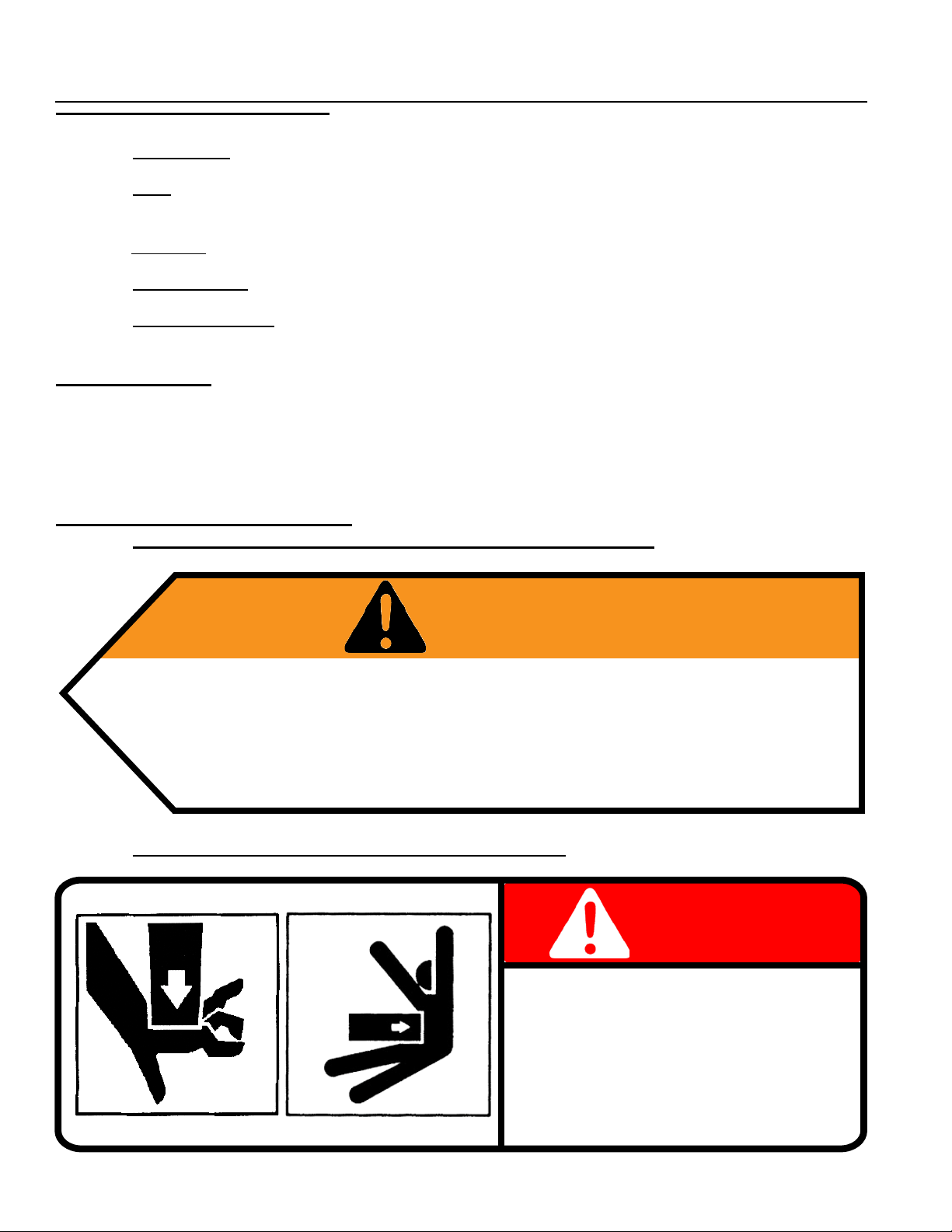
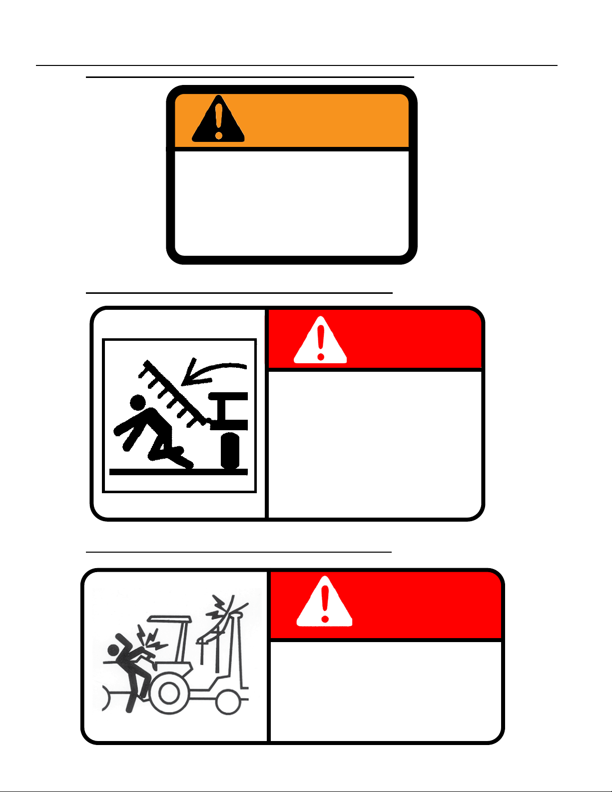
1. PN 8Z0075 – DECAL FOR REMOVING TRANSPORT LOCKS
WARNING
REMOVE TRANSPORT LOCK(S) BEFORE LOWERING MACHINE.
IF LOCK(S) DO NOT REMOVE FREELY, INSURE THAT
CYLINDERS ARE COMPLETELY FILLED WITH HYDRAULIC
FLUID AND ARE SUPPORTING THE LOAD TO BE LOWERED.
2. PN 8Z0087 – DECAL FOR PINCH POINT HAZARD
FRAME PINCH POINT HAZARD
To prevent serious injury or death from crushing:
• Stay away from frame hinge area when folding
wings.
• Keep others away.
• Do not fold wings when bystanders are present.
8Z0075
DANGER
KEEP AWAY
1-2
8Z0087
Page 9
SECTION 1 - SAFETY
3. PN 8Z0202 (3.5”) & 8Z0204 (5.5)” – DECAL FOR COMPANY IDENTIFICATION
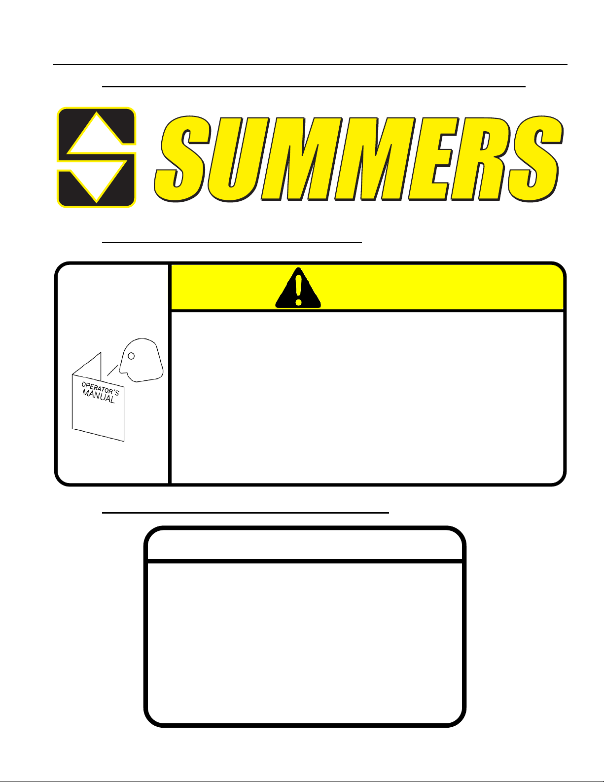
4. PN 8Z0276 – DECAL FOR GENERAL CAUTION
CAUTION
1. Read and understand Operator’s Manual before using machine.
2. For Sprayers:
a. Read and follow chemical manufacturers’ WARNINGS, instructions and procedures before
using.
b. Use recommended personal protective equipment to reduce or eliminate chemical contact.
c. Never run pump dry.
3. Verify all safety devices and shields are in place before using machine.
4. Keep hands, feet, hair and clothing away from moving parts.
5. Stop engine, place all controls in neutral, set parking brakes, remove ignition key and wait for
all moving parts to stop before servicing, adjusting, maintaining or unplugging.
6. Be careful when working around high pressure hydraulic system.
7. Do not allow riders.
8. Check all wheel bolts DAILY for tightness.
9. Refer to Operator’s Manual for periodic and annual maintenance.
10. For Towed Implements, DO NOT EXCEED 20 MPH.
®
8Z0276
5. PN 8Z0340 – DECAL FOR REPHASING CYLINDERS
IMPORTANT
TO REPHASE CYLINDERS, RAISE
MACHINE AND MAINTAIN HYDRAULIC
PRESSURE TEN SECONDS AFTER
CYLINDERS ARE FULLY EXTENDED.
QUICKLY RETRACT CYLINDERS AT
LEAST 1/2”. REPHASING SHOULD BE
DONE EVERY HOUR OF OPERATION TO
MAINTAIN UNIFORM TILLAGE DEPTH.
1-3
8Z0340
Page 10
SECTION 1 - SAFETY
6. PN 8Z0342 – DECAL FOR INSTALLING CYLINDER LOCKS
WARNING
TO AVOID INJURY
INSTALL CYLINDER
LOCKS BEFORE
TRANSPORTING OR
SERVICING MACHINE.
7. PN 8Z0344 – DECAL FOR STAYING CLEAR OF WINGS
8Z0342
DANGER
TO AVOID INJURY OR DEATH
STAND CLEAR OF MACHINE
WHEN WINGS ARE BEING
RAISED AND LOWERED.
MECHANICAL OR HYDRAULIC FAILURE CAN ALLOW
WINGS TO FALL RAPIDLY.
8Z0344
8. PN 8Z0346 – DECAL FOR ELECTROCUTION DANGER
DANGER
TO AVOID INJURY OR DEATH
DO NOT CONTACT
ELECTRICAL LINES.
1-4
8Z0346
Page 11

SECTION 1 - SAFETY
9. PN 8Z0348 – DECAL FOR GAUGE WHEEL DEPTH
10. PN 8Z0800 – AMBER REFLECTOR
11. PN 8Z0805 – RED-ORANGE REFLECTOR
12. PN 8Z0810 – RED REFLECTOR
SAFETY LIGHT OPERATION
The Summers Safety Light Kit is equipped with a 7 pin connector which meets SAE J560 specication. To protect 7 pin connector, store in dust cap (8K8067) when not attached to towing vehicle.
On most towing vehicles WITHOUT brake lights:
Amber lights will turn on with ashers or turn signals.
Red lights will turn on with parking, road or eld lights.
On most towing vehicles WITH brake lights:
Amber lights will turn on with ashers, turn signals OR when brake is applied.
Red lights will turn on with parking or road lights.
1-5
Page 12
1-6
SECTION 1 - SAFETY
Page 13

SECTION 2 – ASSEMBLY INTRODUCTION
GENERAL ASSEMBLY SAFETY PRACTICES
1. READ AND UNDERSTAND Operator’s Manual before assembly of machine.
2. Machine should be assembled in a horizontal (eld) position only.
3. If machine is to be assembled INDOORS, check that exit door is a MINIMUM OF 20’6”
WIDE. Height requirement varies from 10’8” to 18’0”. Shanks may be left off to reduce
height and width requirement.
4. Reference to “RIGHT” and “LEFT” is determined when machine IS VIEWED FROM THE
REAR.
5. Reference to “FORWARD” means TOWARDS THE TRACTOR.
6. Reference to “REAR” means AWAY FROM THE TRACTOR.
SAFETY-ALERT SYMBOL
This symbol is an alert to the potential
for personal injury. This symbol means
ATTENTION! BECOME ALERT!
YOUR PERSONAL SAFETY IS INVOLVED!
2-1
Page 14
SECTION 2 – ASSEMBLY INTRODUCTION
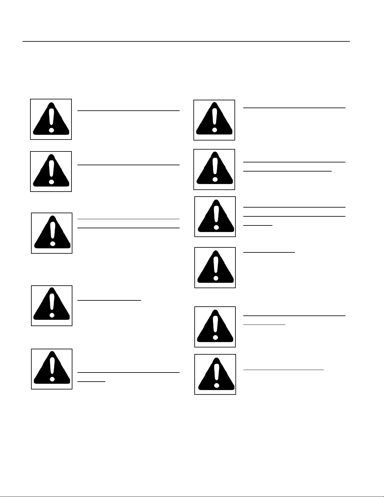
GENERAL SAFETY PRACTICES
YOU ARE RESPONSIBLE
for the safe assembly of the
machine.
DO NOT ALLOW CHILDREN
or other unauthorized persons
within the assembly area.
WEAR PERSONAL
PROTECTIVE EQUIPMENT
which includes a hard hat,
eye protection, work gloves
and steel toed boots with slip
resistant soles.
BLOCK UP ANY RAISED PART
of the machine. Be sure machine
is stable after blocking.
ALWAYS INSPECT LIFTING
CHAINS AND SLINGS for
damage or wear.
BE SURE LIFTING DEVICE
IS RATED TO HANDLE THE
WEIGHT.
STOP ENGINE, place all controls in neutral, set parking
brakes, remove ignition key and
wait for all moving parts to stop
before servicing or adjusting.
DO NOT MODIFY the equipment or substitute parts in any
way. Unauthorized modication
may impair the function and/or
safety of the machine.
USE SUITABLE LIFTING
DEVICE for components which
could cause personal injury.
BE SURE PRESSURE IS
RELIEVED from hydraulic
circuits before servicing or
disconnecting from tractor.
USE EXTREME CARE when
assembling, servicing and
adjusting.
2-2
Page 15
SECTION 2 – SET-UP OF CENTER SECTION (16’-20’)
1. Place front and rear center section on oor with bolt plates facing each other.
2. ATTACH sections with 48 – 3/4x2-1/4” bolts, lock washers and nuts as shown.
3/4" N
8X0260
8T4030 - 16' REAR
8CC4028 - 20' REAR (SHOWN)
8X0306
3/4" LW
CENTER2/15/2011 9T2012H.iam/
8X0112
3/4X2-1/4"
8X0306
3/4" LW
3/4" N
8X0260
8K5515
3/4 X 4 X 6"
8CC5018
8CC5230
8T4015
16' & 20' CENTER
2-3
Page 16
CENTER W-CYL.ATTCH3/19/2014
9T2012H/
8X0260
3/4" N
8X0306
3/4" LW
8K5515
3/4 X 4-1/16 X 6"
8X0286
1 1/2" JN
SECTION 2 – SET-UP OF CENTER SECTION (16’-20’)
2-4
8CC4000
8K1640
7/16" LNUT
8X0234
q
8X0044
7/16" X 3-1/2"
8T4101
8X0285
1 1/2" N
8X0044
7/16" X 3-1/2"
8T3640
8X0234
7/16" LNUT
8D9108
8T3620
8T4224
8K9106
8T1060
8X0044
7/16" X 3-1/2"
8T4166
8A1156
3/8 X 4-1/16 X 5"
8T4190
8X0072
1/2" X 3-3/4"
8K1100
8CC4140
8X0203
3/8" FN
8X0242
NY-LOCK 1/2" N
8R6914
8K7033
11L LRF
Page 17

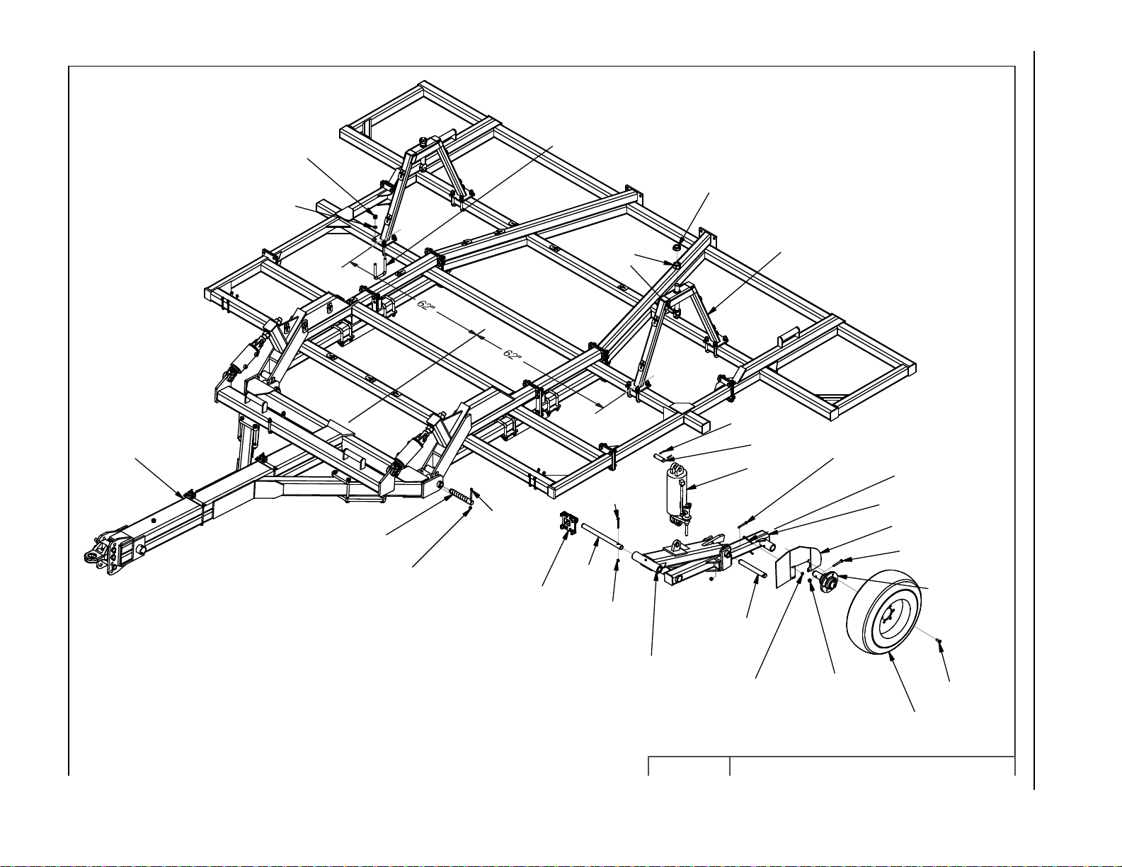
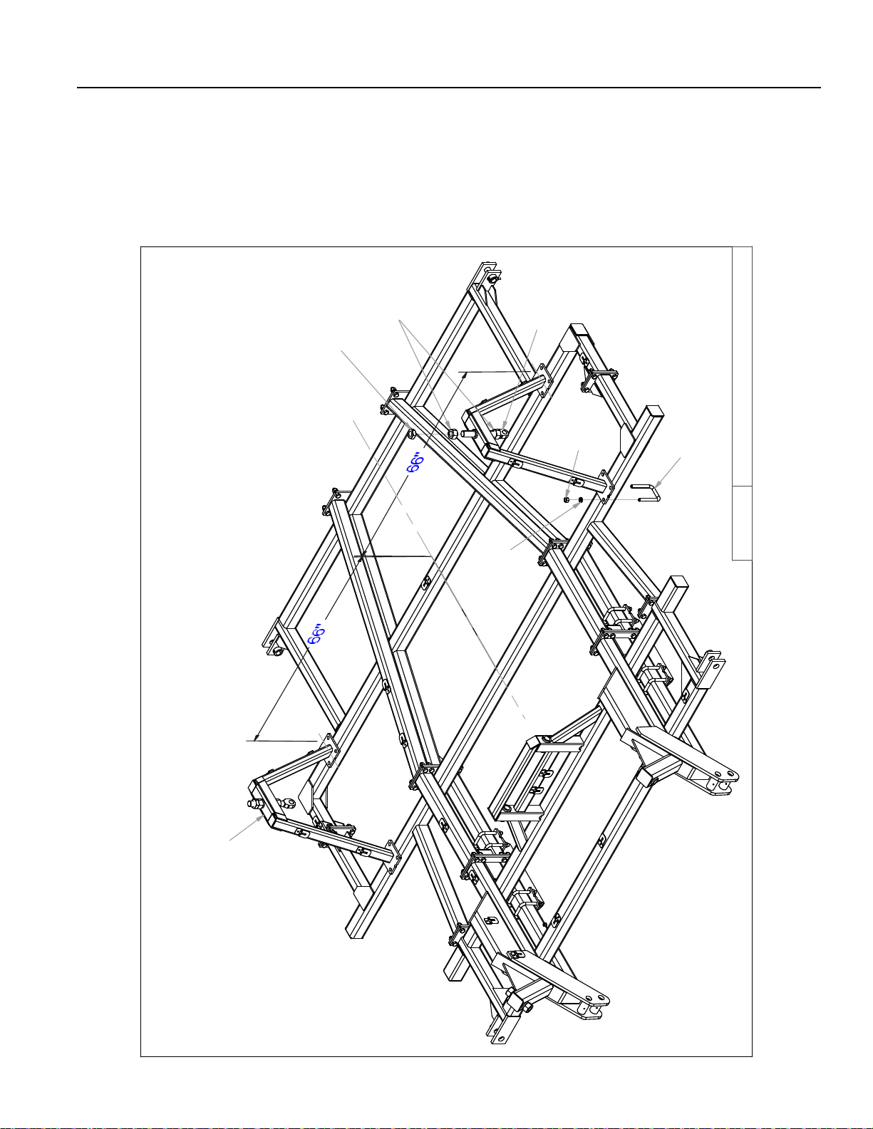
SECTION 2 – SET-UP OF CENTER SECTION (16’-20’)
3. Block center frames off the oor.
4. Install cylinder attach brackets with 3/4” u-bolts.
NOTE: – Locate Rear Cylinder Attach Brackets (8T4224) 62” from frame center.
5. Insert eyebolts (8K1755) into each cylinder attach bracket.
– Tighten 1-1/2” nuts so the same amount of threads are above top nut on all eyebolts.
Insure that cylinder attach holes are aligned when eyebolts are tightened.
NOTE: Drawing for steps 6 through 10 is on previous page.
6. All liftarms will be centered beneath cylinder attach brackets.
– Use 3/4” u-bolts for 4x4 to attach liftarm pivots (8T4100) to frame.
– Slide pivot pin (8T3640) through liftarm and liftarm pivots.
– Insert 7/16 x 3-1/2” bolt in retaining bolts holes. Secure with lock nut.
7. Install walking tandem assemblies to bottom of rear liftarms.
– The left hand side of center frame uses 8T4166 and the right hand side uses 8T4168.
– Slide pivot pin (8T3620) through walking tandem assembly and lift arm.
– Insert 7/16 x 3-1/2” bolt in retaining bolt holes. Secure with lock nut.
– Install 8T4190 (left) and 8T4192 (right) mud guards as shown. Secure with 3/8” u-bolts and
ange nuts.
8. Hang cylinders in correct locations.
– Use pins and rollpins provided.
– Use 6” x 10” (8T1060) on left hand side of center, 5-1/2” x 10” (8T1055) on right hand side.
9. Install 8K1100 axle and hub assembly into each walking tandem. Apply good quality anti-seize to
axles before installation. Retain axle into receiver tube with 1/2 x 3-3/4” bolt and locknut.
10. Attach wheels onto hubs with 9/16” wheel bolts (torque required: 170 ft-lbs).
2-5
Page 18
16' CHISEL PLOW
2-6
90"
78"
65 1/2"
53"
42"
30"
18"
18"
30"
42"
53"
65 1/2"
78"
R
SECTION 2 – SET-UP OF CENTER SECTION (16’)
ISTED SPIKE LAYOUT
L
R
L
R
L -- R - SUGGESTED TW
R
L
6"
0"
6"
L
R
R
L
L
R
L
R
90"
R
SHANK-GANGS11/30/2010 9T1612H.iam/
Page 19
20' CHISEL PLOW
2-7
114"
102"
90"
78"
65 1/2"
53"
42"
30"
18"
18"
30"
42"
53"
65 1/2"
78"
90"
102"
114"
L
R
SECTION 2 – SET-UP OF CENTER SECTION (20’)
ISTED SPIKE LAYOUT
R
L
R
L
L -- R - SUGGESTED TW
R
R
L
6"
0"
6"
L
R
R
L
L
R
L
R
L
L
R
9T2012H.iam/
SHANK-GANGS11/30/2010
Page 20
SECTION 2 – SET-UP OF CENTER SECTION (24’-30’ NARROW)
1. Place front and rear center section on oor with bolt plates facing each other.
2. ATTACH sections with 48 – 3/4x2-1/4” bolts, lock washers and nuts as shown.
3. Block center frames off the oor.
CENTERS2/16/2011
8X0112
8CC5070
3/4X2-1/4"
3/4" N
8X0260
8X0306
3/4" LW
8X0306
3/4" LW
8CC5230
3/4" N
8X0260
8K5515
3/4 X 4 X 6"
9T2412N.iam/
24', 26', 28' & 30' NARROW CENTER
8CC5062
8T4010
2-8
Page 21
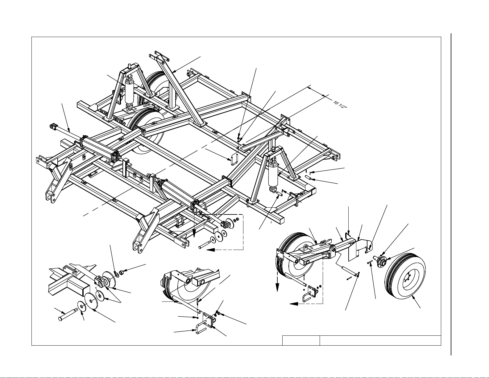
SECTION 2 – SET-UP OF CENTER SECTION (24’-30’ NARROW)
4. Install cylinder attach brackets with 3/4” u-bolts.
NOTE: – Locate Rear Cylinder Attach Brackets (8T4224) 66” from frame center.
5. Insert eyebolts (8K1755) into each cylinder attach bracket.
– Tighten 1-1/2” nuts so the same amount of threads are above top nut on all eyebolts.
Insure that cylinder attach holes are aligned when eyebolts are tightened.
8X0286
8X0285
1 1/2" N
1 1/2" JN
8K1755
CENTER W-CYL.ATTCH3/19/2014
q
3/4" N
8X0306
8X0260
3/4" LW
8K5515
9T2412N.iam/
3/4 X 4-1/16 X 6"
24', 26', 28' & 30' NARROW CYLINDER ATTACHMENT
8T4224
2-9
Page 22

SECTION 2 – SET-UP OF CENTER SECTION (24’-30’ NARROW)
NOTE: Drawing for steps 6 through 10 is on next page.
6. All liftarms will be centered beneath cylinder attach brackets.
– Use 3/4” u-bolts for 4x4 to attach liftarm pivots (8T4100) to frame.
– Slide pivot pin (8T3640) through liftarm and liftarm pivots.
– Insert 7/16 x 3-1/2” bolt in retaining bolts holes. Secure with lock nut.
7. Install walking tandem assemblies to bottom of liftarms.
– The left hand side of center frame uses 8T4166 and the right hand side uses 8T4168.
– Slide pivot pin (8T3620) through walking tandem assembly and lift arm.
– Insert 7/16 x 3-1/2” bolt in retaining bolt holes. Secure with lock nut.
– Install 8T4190 (left) and 8T4192 (right) mud guards as shown. Secure with 3/8” u-bolts and
ange nuts.
8. Hang cylinders in correct locations.
– Use pins and rollpins provided.
– Use 5-1/2” x 10” (8T1055) on left hand side of center, 5 x 10” (8T1050) on right hand side of
center.
9. Install 8K1100 axle and hub assembly into each walking tandem. Apply good quality anti-seize
to axles before installation. Retain axle into receiver tube with 1/2 x 3-3/4” bolt and locknut.
10. Attach wheels onto hubs with 9/16” wheel bolts (torque required: 170 ft-lbs).
11. Attach wing transport locks to center frame with 3/4” u-bolts.
– Locate inside edge of bolt plate 16-1/2” away from frame center.
– Install 1/2 x 6” pins in inside storage holes of transport lock.
12. Insert 1-1/2 x 10-3/8” eyebolts into wing lift cylinder attach base.
– Leave 1-1/2” nuts loose, they will need to be adjusted after wing is installed.
13. Attach wing lift cylinders to frame with pins and roll pins.
2-10
Page 23
8D9524
8T1050
8CC4325
8K5515
3/4 X 4 X 6"
24', 26', 28' & 30' NARROW
8X0260
3/4" N
SECTION 2 – SET-UP OF CENTER SECTION (24’-30’ NARROW)
8X0306
3/4" LW
8T1055
8D9108
1/4 X 2" RP
2-11
8D9108
1/4 X 2" RP
8CC4140
8X0316
1" FW
8K9106
8K9106
8A1156
3/8 X 4-1/16 X 5"
8T4166
8T4190
8X0203
3/8" FN
8X0242
NY-LOCK 1/2" N
8K1100
A
8T3300
8L0252
DETAIL A
8L0252
8T3800
8X0282
8T3800
8T3640
8X0234
7/16" LNUT
8K5515
3/4 X 4 X 6"
DETAIL B
8X0044
7/16" X 3-1/2"
8X0306
3/4" LW
8T4100
8X0260
3/4" N
B
2/9/2012 9T2412N.iam/
8X0234
7/16" LNUT
8X0072
1/2" X 3-3/4"
CENTER W-TRANSPORT
8K7033
Page 24
SECTION 2 – SET-UP OF CENTER SECTION (24’-30’ NARROW)
14. Attach hitch to center with 8K1640.
NOTE: Center with 1-1/2” ID 10 GA at washers.
15. Install 7/16x3-1/2” retaining bolts through hitch pivot pins. Secure with lock nuts.
16. Attach hydraulic hose holder and tip holder with 3/4 x 1-1/4” bolt and at washer.
17. Attach hitch jack to jack spool.
18. Remove blocks from under center frame and allow wheel assemblies to support machine. Block
tires to prevent movement.
19. Add depth control cylinder locks and storage bases.
20. Install SMV sign mounting bracket and sign at center of rear rank.
8X021 1
5/16" FN
8K8200
8X002 1A
5/16 X 1"
8S1124
8X0203
3/8" FN
8D8523
8S112 6
8T4350
8X0306
3/4" L W
8T4380
8X0260
3/4" N
8X0120
3/4" X 9"
8X0044
7/16" X 3-1/2"
7CC0250
8X0234
7/16" LNU T
8K164 0
8X0402
8CC4010
8X0440
8X0240
1/2" N
8X0303
1/2" LW
B
A
8X0223
1/4" FN
8S112 0
8K8067
3/8 X 4-1 /16 X 5"
8D8490
8A1156
1/4 X 3/ 4"
8X0000
DET AIL B
DETAIL A
8X0110
3/4 X 1. 25"
8D8500
8X0318
3/4" FW
HITCH-LOCKS12/1/2010 9T2412N.iam/
2-12
Page 25
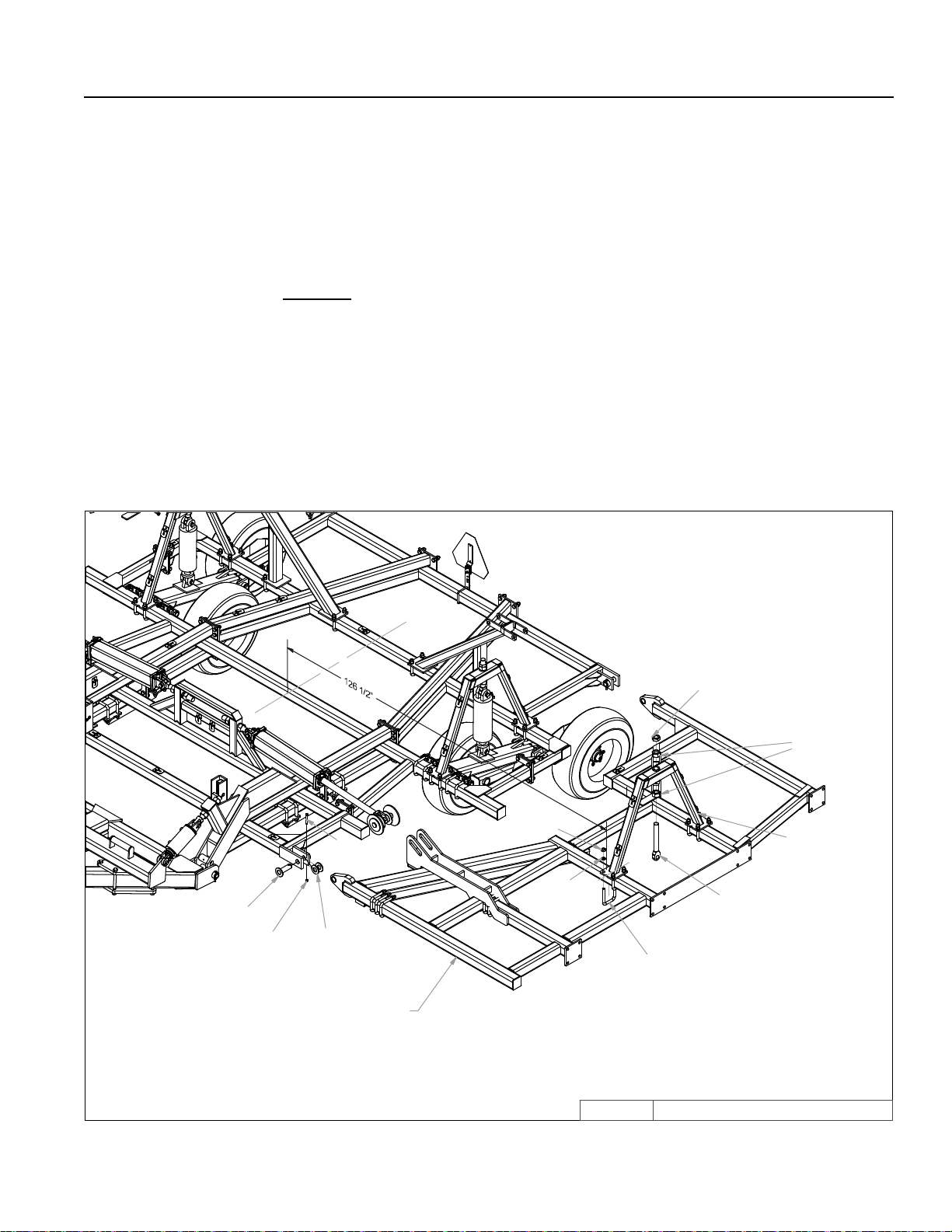
SECTION 2 – SET-UP OF WINGS (24’-30’NARROW)
NOTE: It is recommended to set up both sides of machine at the same time. The left hand side is
shown.
1. Attach wing to center section with pins, washers, bolts and locknuts.
– Washers (8C6015) are used to center wing in hinges and prevent shift.
2. Fasten cylinder attach brackets with 3/4” u-bolts.
– Locate brackets: 126 1/2” from center of machine.
3. Insert eyebolts (8K1755) into cylinder attach bracket.
– Tighten 1-1/2” nuts so the same amount of threads are above top nut on all eyebolts. Insure
that cylinder attach holes are aligned when eyebolts are tightened.
24', 26', 28' & 30' NARROW WING
7/16" X 3-1/2"
8T3600
8X0234
7/16" LNUT
8T4035 (24', 26', 28', 30' LEFT)
8T4037 (24', 26', 28', 30' RIGHT)
8C6015
8X0044
q
8X0260
3/4" N
8X0306
3/4" LW
8K5515
3/4 X 4-1/16 X 6"
8X0286
1 1/2" JN
8K1755
8X0285
1 1/2" N
8T4224
2-13
9T2412N.iam/
WING3/19/2014
Page 26
24', 26', 28' & 30' NARROW WING
8X0242
8T4175
8L0300
NY-LOCK 1/2" N
SECTION 2 – SET-UP OF WINGS (24’-30’NARROW)
2-14
1/2" X 4-1/2"
8X0074
8T4174
8S0660
8X0077
1/2" X 7-1/2"
8X0242
NY-LOCK 1/2" N
8CC4140
8X0240
1/2" N
8T4176 - LEFT
8T4177 - RGHT (SHOWN)
A
8T4168
8T4100
8K1100
8X0303
1/2" LW
B
8S0660
DETAI L B
8K7033
8R6914
DETAI L A
8K4178 - LEFT
8K4179 - RGHT (SHOWN)
WING-TRANSPORT2/21/2013 9T2412N.iam/
Page 27

SECTION 2 – SET-UP OF WINGS (24’-30’NARROW)
4. Center liftarm under cylinder attach brackets.
– Use 3/4” u-bolts for 4x4 to attach liftarm pivots (8T4100) to frame.
– Slide pivot pin (8T3640) through liftarm and liftarm pivots.
– Insert 7/16 x 3-1/2” bolt in retaining bolt holes. Secure with lock nut.
5. Install walking tandem assembly to bottom of liftarms.
– The left hand wing uses an 8T4168.
– The right hand wing uses an 8T4166.
– Slide pivot pin (8T3620) through walking tandem assembly and liftarm.
– Insert 7/16 x 3-1/2” bolt in retaining bolt holes. Secure with lock nut.
6. Hang cylinders in appropriate location. Use pins and roll pins.
– Rod end of cylinder (positioned down) attaches to lift arm.
– Use 6 x 10” (8T1060) on left hand wing.
– Used 4-1/2 x 10” (8T1045) on right hand wing.
7. Install 8K1100 axle and hub assembly into each walking tandem. Apply good quality anti-seize to
axles before installation. Retain axle into receiver tube with 1/2 x 3-3/4” bolt and locknut.
8. Attach wheels onto hubs with 9/16” wheel bolts (torque required: 170 ft-lbs).
9. Install optional wing extensions. One-shank extensions are used on the 26’. Both one-shank and
two-shank extensions are used on the 28’.
– One-shank extension must be placed on rear rank.
– Two-shank extension must be placed on second and third ranks (See page 2-16).
– Mounting bolts must point toward outside of machine. (Trip assembly interference will occur
if this is not followed.)
10. Hang trip assemblies according to layout provided (See pages 2-17 through 2-19).
NOTE: Steps 10-11 can be done after cylinders are lled with oil and machine is raised.
– Use 3/4” u-bolts for 4 x 4 tube with 3/4” lock washers and 3/4” nuts.
– Tighten u-bolts an equal amount on top and bottom. The same amount of threads should
appear on top and bottom of u-bolt.
2-15
Page 28
2-16
8X0112
3/4X2-1/4"
8CC4075
28' ONLY
8T4060
26'-28' ONLY
SECTION 2 – SET-UP OF WINGS (24’-30’NARROW)
8X0306
3/4" LW
8X0260
3/4" N
WING-EXT12/2/2010 9T2812N.iam/
Page 29
2-17
8X0112
3/4X2-1/4"
8X0306
3/4" LW
SECTION 2 – SET-UP OF WINGS (24’-30’NARROW)
8T4035
8T4060
8T4075
8X0260
3/4" N
9T3012N.iam/
30' NRRW WNG EXT2/14/2012
Page 30
24' NARROW CENTER
CHISEL PLOW
SECTION 2 – SET-UP (24’-30’NARROW)
2-18
L -- R - SUGGESTED TWISTED SPIKE LAYOUT
R
R L
L
L R
L
L R
L
R
L
R L
L
R R
0"
6"18"30"42"54"66"78"90"102"114"126"138" 6" 18" 30" 42" 54" 66" 78" 90" 102" 114" 126" 138"
R
R
L
L R
L
R
WEIGHT PACKAGE
LOCATION
24' CHSL SHANKS-GANGS12/1/2010 9T2412N.iam/
Page 31

26' CHISEL PLOW
SECTION 2 – SET-UP (24’-30’ NARROW)
2-19
L -- R - SUGGESTED TWISTED SPIKE LAYOUT
R
R
L
L
L
L
L
R L L
R L R R
L
R
6"18"30"42"54"66"78"90"102"114"1 26"138"150" 6" 18" 30" 42 " 54" 66" 78" 90" 102" 11 4" 12 6" 138" 15 0"
0"
R
L
R
L
R
L R
WEIGHT PKG
L
R
R
26' CHSL SHANK LAYOUT12/2/2010 9T2612N.iam/
Page 32

28' CHISEL PLOW
WEIGHT PKG
SECTION 2 – SET-UP (24’-30’ NARROW)
2-20
R
L -- R - SUGGESTED TWISTED SPIKE LAYOUT
R
R
L
L R
L
L
L
R L R R
L
R
L
6"18"30"42"54"66"78"90"102"114"126"138"150"162" 6" 18" 30" 42" 54" 66" 78" 90" 102" 114" 126" 138" 150" 162"
0"
R
L
L
R
R
L
L R
L
R
L
R
28' CHSL SHANK LAYOUT12/2/2010 9T2812N.iam/
Page 33

30' NARROW CHISEL PLOW
SECTION 2 – SET-UP (24’-30’NARROW)
2-21
R R
L
L L R
R
L
LR
R
L R
R
L
L
0"6"18"30"42"54"66"78"90"102"114"126"138"150"162"174" 6" 18" 30" 42" 54" 66" 78" 90" 102" 114" 126" 138" 150" 162" 174"
L
L
R
R
R
L
R
L R
L
R
R
L
L
L -- R - SUGGESTED TWISTED SPIKE LAYOUT
30' NRW CHSL SHANK LAYOUT2/3/2012 9T3012N.iam/
Page 34

SECTION 2 – SET-UP (24’-30’NARROW)
11. Install shanks into trip assemblies.
– Install rear 3/4 x 4” bolt. Slide shank into shank holder. Install front bolt. Securely tighten.
– Shanks will t snuggly into shank holder. If tapping bottom of shank does not work, it may
be necessary to remove burr and/or paint from shank or shank holder.
2-22
Page 35

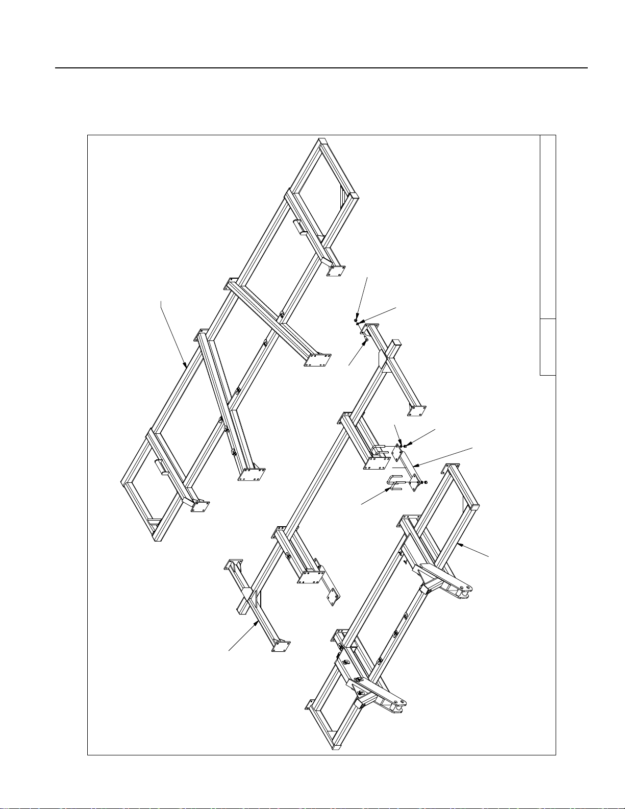
SECTION 2 – SET-UP OF CENTER SECTION (32’-44’)
1. Place front and rear center section on oor with bolt plates facing each other.
2. ATTACH sections with 24 – 3/4x2-1/4” bolts, lock washers and nuts as shown.
2-23
Page 36

SECTION 2 – SET-UP OF CENTER SECTION (32’-44’)
3. Block center frames off the oor.
4. Install cylinder attach brackets with 3/4” u-bolts.
NOTE: – Locate Rear Cylinder Attach Brackets (8T4224) 62” from frame center.
– Locate Front Cylinder Attach Bracket (8T4205) at front center as shown.
5. Insert eyebolts (8K1755) into each cylinder attach bracket.
– Tighten 1-1/2” nuts so the same amount of threads are above top nut on all eyebolts.
Insure that cylinder attach holes are aligned when eyebolts are tightened.
2-24
Page 37

SECTION 2 – SET-UP OF CENTER SECTION (32’-44’)
NOTE: Drawing for steps 6 through 10 is on the next page.
6. All liftarms will be centered beneath cylinder attach brackets.
– Use 3/4” u-bolts for 4x4 to attach liftarm pivots (8T4100) to frame.
– Slide pivot pin (8T3640) through liftarm and liftarm pivots.
– Insert 7/16 x 3-1/2” bolt in retaining bolts holes. Secure with lock nut.
7. Install walking tandem assemblies to bottom of rear liftarms.
– The left hand side of center frame uses a left hand assembly (8T4166) and the right hand
side uses a right hand assembly (8T4168).
– Slide pivot pin (8T3620) through walking tandem assembly and lift arm.
– Insert 7/16 x 3-1/2” bolt in retaining bolt holes. Secure with lock nut.
– Install 8T4190 (left) and 8T4192 (right) mud guards as shown. Secure with 3/8” u-bolts and
ange nuts.
7a. Install walking tandem assembly to bottom of front center lift arm.
– Check inside surface of walking tandem assembly (8T4132). A 3-3/4” diameter surface around
the 1-1/2” dia. pivot hole must be smooth and burr-free. Remove any welding spatter or
roughness prior to further assembly. Install snap rings (8K1920) past grooves of lower pivot
tube. Install V-seals over lower pivot tube until solid side is against snap ring. Protect lip of
V-seals during assembly.
– Install walking tandem assembly to bottom of center liftarm. Mount so right axle is towards
front. Insert pivot pin (8T3620) through walking tandem assembly and liftarm. Retain
with 7/16” x 3-1/2” bolt and lock nut.
– Push V-seals against walking tandem assembly and secure by placing snap ring into
groove.
8. Hang cylinders in correct locations.
– Use pins and rollpins provided.
– Use 5-1/2” x 10” (8T1055) on left hand side of center, 5 x 10” (8T1050) on right hand side of
center, and 4 x 10” (8T1040) on center wheel assembly.
– The front center lift arm (8T4130) has two cylinder attach locations. If chisel plow will have a
full set of mounted harrows, use rear cylinder attach hole. Cylinder attach location can be
changed based on nal adjustments. Connecting front center cylinder to rear hole will lower
front end of chisel plow in transport position.
9. Install 8K1100 axle and hub assembly into each walking tandem. Apply good quality anti-seize to
axles before installation. Retain axle into receiver tube with 1/2 x 3-3/4” bolt and locknut.
10. Attach wheels onto hubs with 9/16” wheel bolts (torque required: 170 ft-lbs).
2-25
Page 38

SECTION 2 – SET-UP OF CENTER SECTION (32’-44’)
11. Attach wing transport locks to center frame with 3/4” u-bolts.
– Located outside edge of bolt plate 78-3/8” away from frame center.
– Install 1/2 x 6” pins in inside storage holes of transport lock.
12. Insert 1-1/2 x 10-3/8” eyebolts into wing lift cylinder attach base.
– Leave 1-1/2” nuts loose, they will need to be adjusted after wing is installed.
13. Attach wing lift cylinders to frame with pins and roll pins.
– 32’ through 36’ machines use 4 x 36” cylinders (8K9640).
– 38’ through 44’ machines use 5 x 36” cylinders (8K9650).
2-26
Page 39

SECTION 2 – SET-UP OF CENTER SECTION (32’-44’)
14. Attach hitch to center with 1-1/2” x 10-5/8” pins.
NOTE: Center with 1-1/2” ID 10 GA at washers.
15. Install 7/16x3-1/2” retaining bolts through hitch pivot pins. Secure with lock nuts.
16. Attach hydraulic hose holder and tip holder with 3/4 x 1-1/4” bolt and at washer.
17. Attach hitch jack to jack spool.
18. Remove blocks from under center frame and allow wheel assemblies to support machine. Block
tires to prevent movement.
19. Add depth control cylinder locks and storage bases.
– Attach locks for rear cylinders by liftarm pivots located closest to center of machine.
– Locate lock for front center cylinder on front 4 x 4 tube.
20. Install SMV sign mounting bracket and sign at center of rear rank.
21. Place adjustment wrenches on clevis pins found on left side of center section. Retain with hair
pin clips.
2-27
Page 40

2-28
SECTION 2 – SET-UP OF 32’ BASE MACHINES (32’-38’)
Page 41

SECTION 2 – SET-UP OF 32’ BASE MACHINES (32’-38’)
NOTE: It is recommended to set up both sides of machine at the same time. The left hand side is
shown.
1. Attach wing to center section with pins, washers, bolts and locknuts.
– Washers are used to center wing in hinges and prevent shift.
2. Fasten cylinder attach brackets with 3/4” u-bolts.
– Locate brackets: 169” from center of machine for 32’-38’ chisels.
3. Insert eyebolts (8K1755) into cylinder attach bracket.
– Tighten 1-1/2” nuts so the same amount of threads are above top nut on all eyebolts. Insure
that cylinder attach holes are aligned when eyebolts are tightened.
4. Center liftarm under cylinder attach brackets.
– Use 3/4” u-bolts for 4x4 to attach liftarm pivots (8T4100) to frame.
– The inside pivot will be attached with 3/4 x 6” bolts and a trip assembly. (See step 20)
– Slide pivot pin (8T3640) through liftarm and liftarm pivots.
– Insert 7/16 x 3-1/2” bolt in retaining bolt holes. Secure with lock nut.
5. Install walking tandem assembly to bottom of liftarm.
– The left hand wing uses an 8T4168.
– The right hand wing uses an 8T4166.
– Slide pivot pin (8T3620) through walking tandem assembly and liftarm.
– Insert 7/16 x 3-1/2” bolt in retaining bolt holes. Secure with lock nut.
6. Hang cylinders in appropriate location. Use pins and roll pins.
– Rod end of cylinder (positioned down) attaches to lift arm.
– Use 6 x 10” (8T1060) on left hand wing.
– Used 4-1/2 x 10” (8T1045) on right hand wing.
7. Install 8K1100 axle and hub assembly into each walking tandem. Apply good quality anti-seize to
axles before installation. Retain axle into receiver tube with 1/2 x 3-3/4” bolt and locknut.
8. Attach wheels onto hubs with 9/16” wheel bolts (torque required: 170 ft-lbs).
2-29
Page 42

2-30
SECTION 2 – SET-UP OF 32’ BASE MACHINES (32’-38’)
Page 43

SECTION 2 – SET-UP OF 32’ BASE MACHINES (32’-38’)
9. Install optional wing extensions.
– One-shank extension must be placed on rear rank.
– Two-shank extension must be placed on middle two ranks.
– Three-shank extension with gauge wheel plate must be attached to the rst and second
rank.
– Mounting bolts must point toward outside of machine. (Trip assembly interference will occur
if this is not followed.)
10. Install gauge wheel support (8T4090) onto wing with 7/8 x 2-1/2” bolts.
NOTE: Steps 10 through 15 may have been pre-assembled at factory.
11. Apply anti-seize to jack bolt (8T6000) threads. Screw jack bolt into axle holder (8T4094) far enough
to see hole on bottom of bolt through hole in axle holder.
– Insert 3/16 x 2” roll pin. Insert pin far enough so it will clear tube when rotated.
12. Place gauge wheel depth decal on axle holder.
– Locate decal 1” from bottom of 4 x 4 tube.
– Make sure that decal faces the front of the machine.
– Decal should be placed off to one side of axle holder to avoid seam on support tube.
13. Slide axle holder and jack bolt into gauge wheel support. Slide 1-1/4” at washer onto bolt and
turn 1-1/4” slotted nut on.
– Do not tighten slotted nut.
14. Add gauge wheel screw top onto jack bolt.
– Insert 1/2 x 2-1/4” bolt into screw top and bolt, secure with locknut.
15. Attach gauge wheel jack handle to screw top.
– Install 3/8 x 2” bolt in handle and screw top. Secure with lock nut.
– Do not over tighten. Handle must pivot freely.
2-31
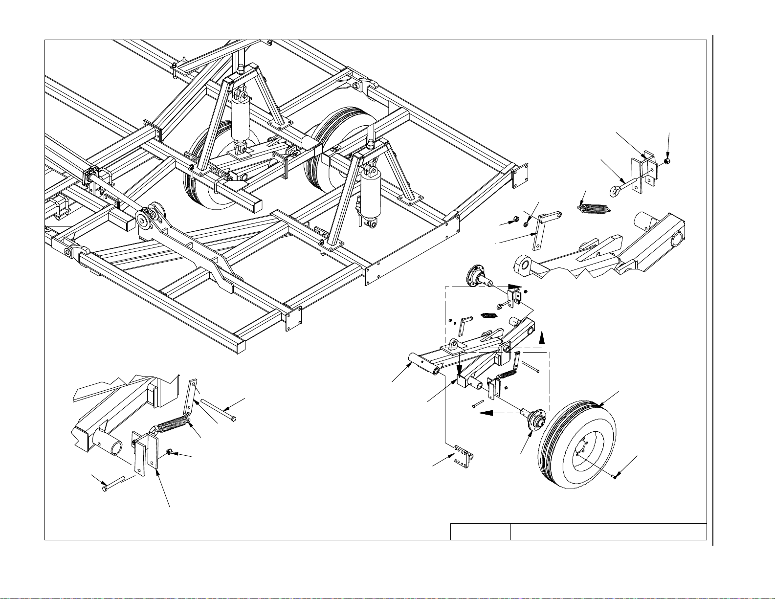
Page 44

SECTION 2 – SET-UP OF 32’ BASE MACHINES (32’-38’)
16. Check free operation of gauge wheel assembly.
– Loosen or tighten slotted nut for optimum performance of gauge wheel.
– Install 3/16” x 2” roll pin after slotted nut is adjusted properly.
16a. Adjust clearance between 8T4090 and 8T4094 with 3/4” set bolts and jam nuts.
17. Install 8K1100 axle and hub assembly into each receiver tube. Apply good quality anti-seize to
axles before installation. Retain axle into receiver tube with 1/2 x 3-3/4” bolt and locknut.
18. Attach tire/wheel to hub with 9/16” wheel bolts (torque required: 170 ft-lbs).
19. Hang trip assemblies according to layout provided.
NOTE: Steps 19-21 can be done after cylinders are lled with oil and machine is raised.
– Use 3/4” u-bolts for 4 x 4 tube with 3/4” lock washers and 3/4” nuts.
– Tighten u-bolts an equal amount on top and bottom. The same amount of threads should ap-
pear on top and bottom of u-bolt.
20. Trip assemblies located at 162” on 32’ base machines will be attached with 3/4 x 6-1/2” bolts.
These bolts will also hold the liftarm pivot bracket at that location.
2-32
Page 45

2-33
SECTION 2 – SET-UP OF 32’ BASE MACHINES 700# TRIP (32’-38’ SHOWN)
Page 46

2-34
SECTION 2 – SET-UP OF 32’ BASE MACHINES 1050# TRIP (32’-36’ SHOWN)
Page 47

SECTION 2 – SET-UP OF 32’ BASE MACHINES (32’-38’)
21. Install shanks into trip assemblies.
– Install rear 3/4 x 4” bolt. Slide shank into shank holder. Install front bolt. Securely tighten.
– Shanks will t snuggly into shank holder. If tapping bottom of shank does not work, it may be
necessary to remove burr and/or paint from shank or shank holder.
2-35
Page 48

2-36
SECTION 2 – SET-UP OF 40’ BASE MACHINES (40’-44’)
Page 49

SECTION 2 – SET-UP OF 40’ BASE MACHINES (40’-44’)
NOTE: It is recommended to set up both sides of machine at the same time. The left hand side is
shown.
1. Attach wing to center section with pins, washers, bolts and locknuts.
– Washers are used to center wing in hinges and prevent shift.
2. Attach 4’ extension to base wing. Extension braces lay on top of base wing, remaining bolt plates
mate with bolt plates of base wing.
– Mating bolt plates on back 3 ranks should have bolts pointed toward outside of machine. Bolt
plate on rst rank should have bolts pointed toward center of frame.
– 3 u-bolts are used to secure front support on top of rst rank.
3. Fasten cylinder attach brackets with 3/4” u-bolts.
– Locate bracket 217” from machine center.
4. Insert eyebolts (8K1755) into cylinder attach bracket.
– Tighten 1-1/2” nuts so the same amount of threads are above top nut on all eyebolts. Insure
that cylinder attach holes are aligned when eyebolts are tightened.
5. Center liftarm under cylinder attachment brackets.
– Use 3/4” u-bolts for 4 x 4 to attach liftarm pivots (8T4100) to frame.
– Inside pivot will be attached with 3/4 x 6” bolts and a trip assembly. (See step 21).
– Slide pivot pin (8T3640) through liftarm and liftarm pivots.
– Insert 7/16 x 3-1/2” bolt in retaining bolt holes. Secure with lock nut.
6. Install walking tandem assembly to bottom of liftarm.
– The left hand wing uses an 8T4168.
– The right hand wing uses an 8T4166.
– Slide pivot pin (8T3620) through walking tandem assembly and liftarm.
– Insert 7/16 x 3-1/2” bolt in retaining bolt holes. Secure with lock nut.
7. Hang cylinders in appropriate location. Use pins and roll pins provided.
– Rod end of cylinder (positioned down) attaches to lift arm.
– Use 6 x 10” (8T1060) on left hand wing.
– Use 4-1/2 x 10” (8T1045) on right hand wing.
8. Install 8K1100 axle and hub assembly into each walking tandem. Apply good quality anti-sieze to
axles before installation. Retain axle into receiver tube with 1/2 x 3-3/4” bolt and locknut.
9. Place wheels on hubs with 9/16” wheel bolts (torque required: 170 ft-lbs).
2-37
Page 50

2-38
SECTION 2 – SET-UP OF 40’ BASE MACHINES (40’-44’)
Page 51

SECTION 2 – SET-UP OF 40’ BASE MACHINES (40’-44’)
10. Install optional wing extensions.
– One-shank extension must be placed on rear rank.
– Two-shank extensions must be placed on middle two ranks.
– Mounting bolts must point toward outside of machine. (Trip assembly interference will occur
if this is not followed.)
11. Install gauge wheel support (8T4090) onto wing with 7/8 x 2-1/2” bolts.
NOTE: Steps 12 through 16 may have been pre-assembled at factory.
12. Apply anti-seize on jack bolt (8T6000) threads. Screw jack bolt into axle holder (8T4094) far
enough to see hole on bottom of bolt through hole in axle holder.
– Insert 3/16 x 2” roll pin. Insert pin far enough so it will clear tube when rotated.
13. Place gauge wheel depth decal on axle holder.
– Locate decal 1” from bottom of 4 x 4 tube.
– Make sure that decal faces the front of the machine.
– Decal should be placed off to one side of axle holder to avoid seam on support tube.
14. Slide axle holder and jack bolt into gauge wheel support. Slide 1-1/4” at washer onto bolt and
turn 1-1/4” slotted nut on.
– Do not tighten slotted nut.
15. Add gauge wheel screw top onto jack bolt.
– Insert 1/2 x 2-1/4” bolt into screw top and bolt. Secure with locknut.
16. Attach gauge wheel jack handle to screw top.
– Install 3/8 x 2” bolt in handle and screw top. Secure with lock nut.
– Do not over tighten. Handle must pivot freely.
2-39
Page 52

SECTION 2 – SET-UP OF 40’ BASE MACHINES (40’-44’)
17. Check free operation of gauge wheel assembly.
– Loosen or tighten slotted nut for optimum performance of gauge wheel.
– Install 3/16” x 2” roll pin after slotted nut is adjusted properly.
17a. Adjust clearance between 8T4090 and 8T4094 with 3/4” set bolts and jam nuts.
18. Install 8K1100 axle and hub assembly into each receiver tube. Apply good quality anti-seize to
axles before installation. Retain axle into receiver tube with 1/2 x 3-3/4” bolt and locknut.
19. Attach tire/wheel to hub with 9/16” wheel bolts (torque required: 170 ft-lbs).
20. Hang trip assemblies according to layout provided.
NOTE: Steps 20-22 can be done after cylinders are lled with oil and machine is raised.
– Use 3/4” u-bolts for 4 x 4 tube with 3/4” lock washers and 3/4” nuts.
– Tighten u-bolts an equal amount on top and bottom. The same amount of threads should ap-
pear on top and bottom of u-bolt.
21. Trip assemblies located at 210” from center will be attached with 3/4” x 6-1/2” bolts. These bolts
will also hold the liftarm pivot bracket at that location.
2-40
Page 53

2-41
SECTION 2 – SET-UP OF 40’ BASE MACHINES (40’-44’)
Page 54

SECTION 2 – SET-UP OF 40’ BASE MACHINES (40’-44’)
22. Install shanks into trip assemblies.
– Install rear 3/4 x 4” bolt. Slide shank into shank holder. Install front bolt. Securely tighten.
– Shanks will t snuggly into shank holder. If tapping bottom of shank does not work, it may
be necessary to remove burr and/or paint from shank or shank holder.
31” STD
34” OPT
2-42
Page 55

SECTION 2 – HYDRAULIC SET-UP (16’-30’ NARROW)
1. Hydraulic hoses and ttings for depth control cylinders can be found on following drawings.
– Rephasing cylinders require that oil from the rod end of rst cylinder goes to base end of
second cylinder and so forth. Cylinders will not operate properly unless they are connected
correctly.
2. Special attention should be paid to routing of hydraulic hoses. Page 2-50 shows layout of hoses
for depth control cylinders.
A. It is best to start by routing the hose for the 6 x 10” cylinder. Make sure there is 60” of hose
ahead of hose holder. This is usually enough hose for safe and easy hook-up to tractor.
B. Route hose along hitch frame. Use plastic clamps provided. Do not tighten until routing is
complete.
– On hitch, and a portion of main frame, 2 clamps are placed on each bolt.
– Clamps are made to have the round surface point towards the surface that you are
mounting to. DO NOT OVER TIGHTEN.
DEPTH CONTROL HYDRAULICS
3/4"-16ORB X 10 JIC(M)
8N6570
3/4" X 570"
TO
TRACTOR
8T1008
PLASTIC
PLUNGER
REPAIR
KIT
8T1010
BOLT ON
POPPET
ASSY
8J5520
8D3212
TO 5.5"
CYL.
8T1015
HPC
MALE TIP, 3/4"-16ORB ISO
TOP VIEW
8J5520
8J5520
3/4"-16ORB X 10 JIC(M)
3/4"-16ORB X 10 JIC(M)
8T1060
6.0" X 10"
8T1006
PLUNGER
8J5510
3/4"-16ORB X 6 JIC(M)
8T2990
CLAMP
8K9106
CYL PIN
8D9108
ROLL PIN
8N4228
1/2" X 228"
16' & 20' MACHINES
MALE TIP, 3/4"-16ORB ISO
8T1055
5.5" X 10"
8D3212
8N4546
1/2" X 546"
3/4"-16ORB X 10 JIC(M) 90° ADP
8J6020
2-43
DISKCHSL-CLTRCHSL/DEPCONHYD7/30/2012
Page 56

SECTION 2 – HYDRAULIC SET-UP (16’-30’ NARROW)
C. Leave plenty of slack by hitch pivot.
– The hitch pivot point will move up and down from transport position to eld position. Hoses
must be loose enough to allow a full range of travel.
D. Continue to route hose for 6 x 10” cylinder along center section of chisel plow.
– Bolts welded to frame will help show correct routing.
E. Use care when stringing hose between center section and wing.
– Leave plenty of slack between points 1 and 2 (Page 2-50) as wing pivots up and
down during eld operation. Hose must not stretch tight.
F. Hose must be routed so it will not be pinched when wing is folded into transport.
– Pull hose tight between points 2 and 3. This will prevent hose from contacting
transport lock (See page 2-50).
G. Route hose up cylinder attach to 6 x 10” cylinder.
H. Route hose from 6 x 10” to 5-1/2 x 10” cylinder along same path as rst hose.
DEPTH CONTROL HYDRAULICS
8J5520
8N6570
3/4" X 570"
TOP VIEW
8D3212
3/4" HOSE CLAMP
TO 5.5"
CYL.
1/2" X 198"
MALE TIP, 3/4"-16ORB ISO
3/4"-16ORB X 10 JIC(M)
TO
TRACTOR
8T1008
PLASTIC
PLUNGER
REPAIR
KIT
8T2990
8N4198
8R6810
SS BSHNG
8J6020
8J6020
8J6020
8J6020
3/4"-16ORB X 10 JIC(M) 90° ADP
3/4"-16ORB X 10 JIC(M) 90° ADP
3/4"-16ORB X 10 JIC(M) 90° ADP
3/4"-16ORB X 10 JIC(M) 90° ADP
3/4"-16ORB X 10 JIC(M) 90° ADP
8J6020
8N4228
1/2" X 228"
8K9106
CYL PIN
8D9108
ROLL PIN
24'-30' MACHINES
8G2285
NYL. TIE (GREEN)
8N3534
3/8" X 534"
8N4198
1/2" X 198"
CYLINDER PORTS
TOWARDS FRONT
OF MACHINE
8T1010
BOLT ON
POPPET
ASSY
8T1060
8T1015
HPC
8J5520
8J5520
3/4"-16ORB X 10 JIC(M)
3/4"-16ORB X 10 JIC(M)
6.0" X 10"
8T1055
5.5" X 10"
2-44
8J6010
DISKCHSL-CLTRCHSL/DEPCONHYD7/30/2012
8T1045
4.5" X 10"
8T1050
5.0" X 10"
3/4"-16ORB X 6 JIC(M) 90° ADP
Page 57

SECTION 2 – HYDRAULIC SET-UP (16’-30’ NARROW)
I. Use nylon ties to hold rst hose to second hose.
– This hose must be attached to base end (top) of 5-1/2 x 10” cylinder.
J. Route 1/2 x 228” hose from 5-1/2 x 10” to 5 x 10” cylinder.
– This hose must go from rod end (bottom) of 5-1/2 x 10” to base end (top) of 5 x 10” cylinder.
K. Route 1/2” x 198” hose from 5 x 10” to 4-1/2 x 10” cylinder.
– This hose must be routed through points 1, 2 and 3 as explained in steps E and F.
– The hose must go from rod end (bottom) of 5 x 10” to base end (top) of 4-1/2 x 10”.
L. Route hose from 4-1/2 x 10” to front of hitch.
– This hose must follow the same path through points 1, 2, and 3.
– Continue to route hose along center frame and hitch. Bolt locations will help show desired
location for routing.
– Nylon ties should be used by the hose holder loop to keep hoses together.
16' - 30' NARROW CHISEL
HYDRAULIC HITCH
8J5300
#6 JIC(M) TEE
#6 JIC(F-SW) X #6 JIC(M) 90° ADP
8J5700
3/4" ORB X #6 JIC(M)
8D3212
3/4" ORB TIP ISO
8J5510
8CC4010
8C1710
3/8 X 8 X 9"
8W1398
8N3150
2X
8X0202
3/8" LN
8X0120
3/4" X 9"
8X0306
3/4" LW
8N3048
2X
8N3060
8X0260
3/4" N
8CC4012
3/4-16ORB X #6JIC(M) 90° ADP
8J6010
8X0285
1 1/2" N
8P7250
2X
8T2040
2-45
2/9/2012
9T2012H.iam/
16'-28' NRRW HYD HITCH
Page 58

SECTION 2 – HYDRAULIC SET-UP (16’-30’ NARROW)
M. Tighten all plastic hose clamps until hoses are snug but not compressed. Over tightening
hose clamps will damage hydraulic hose. Hydraulic hoses enlarge and shorten when pres-
surized, leave slack between clamps.
N. Charge Wing Lift Cylinders.
– Block rod end of cylinders so cylinders can extend without hitting anything.
– Fully cycle the cylinders several times to make sure that all air has been removed from
system.
– Leave cylinders in fully extended position.
O. Connect rod end of cylinders to wing. Follow these steps and see drawing on Page 2-52.
– Use pivot bolt, washers and collars, 1-1/4” washers, 1” washer and 1” lock nut provided.
– 1-1/4” washers must slide freely inside wing amecuts.
– Do not over tighten lock nut. Pivot bolt must rotate freely.
P. With cylinder attach eyebolts loose, raise chisel plow wings to transport position.
– Fully retract cylinders and let wings rest against transport locks.
– Tighten each eyebolt so pivot bolt and rollers are centered in the wing lift slot.
WING LIFT HYDRAULICS
8J7116
ARROW MUST
POINT TOWARD
CYLINDER
8J5620
3/4" X #6 JIC (F-SW)
8J5200
#10(F)X#6(M) BUSH
8J6030
7/8"X#10(M) 90° ADP
3/4"X3/4" UNION
8J7040
THERMAL RELIEF
8J5680
8A1954
1/4"OD TUBE - 18"
#6 JIC(F-SW) X #6 JIC(M) 90° ADP
#6 JIC(M) TEE
8J5510
3/4" ORB X #6 JIC(M)
8J6030
7/8"X#10(M) 90° ADP
8J5700
8J5300
#6 JIC(F-SW) X #6 JIC(M) 90° ADP
8N3048
3/8" X 48"
8J5700
8N3028
3/8" X 28"
3/4" ORB TIP ISO
8J5620
3/4" X #6 JIC (F-SW)
#10(F)X#6(M) BUSH
24'-30' MACHINE
8D3212
8J5510
3/4" ORB X #6 JIC(M)
8N3360
3/8" X 360"
8J5510
3/4" ORB X #6 JIC(M)
8J7116
8J5200
7/8"X#10(M) 90° ADP
8J6030
8D9524
5.0" X 24"
8J5200
#10(F)X#6(M) BUSH
8D9525
SEAL KIT 5X24"
8J5300
#6 JIC(M) TEE
2-46
9T2412N.iam/
WING LFT HYD2/9/2012
Page 59

SECTION 2 – HYDRAULIC SET-UP (32’-44’)
1. Hydraulic hoses and ttings for depth control cylinders can be found on following drawing.
– Rephasing cylinders require that oil from the rod end of rst cylinder goes to base end of
second cylinder and so forth. Cylinders will not operate properly unless they are connected
correctly.
– 40’ and larger models require extension hoses and unions, shown on drawing below.
2. Special attention should be paid to routing of hydraulic hoses. Page 2-50 shows layout of hoses
for depth control cylinders.
A. It is best to start by routing the hose for the 6 x 10” cylinder. Make sure there is 60” of hose
ahead of hose holder. This is usually enough hose for safe and easy hook-up to tractor.
B. Route hose along hitch frame. Use plastic clamps provided. Do not tighten until routing is
complete.
– On hitch, and a portion of main frame, 2 clamps are placed on each bolt.
– Clamps are made to have the round surface point towards the surface that you are
mounting to. DO NOT OVER TIGHTEN.
C. Leave plenty of slack by hitch pivot.
– The hitch pivot point will move up and down from transport position to eld position. Hoses
must be loose enough to allow a full range of travel.
D. Continue to route hose for 6 x 10” cylinder along center section of chisel plow.
– Bolts welded to frame will help show correct routing.
– Route hose along top of frame by transport lock. Use nylon ties to hold hose in place once
all hoses have been routed.
E. Use care when stringing hose between center section and wing.
– Leave plenty of slack between points 1 and 2 (Page 2-50) as wing pivots up and
down during eld operation. Hose must not stretch tight.
F. Hose must be routed so it will not be pinched when wing is folded into transport.
– Pull hose tight between points 2 and 3. This will prevent hose from contacting
transport lock.
G. On 40’ and larger models, a 3/4 x 60” hose is added to the 588” hose with a union.
– Two more bolt locations will guide routing along frame on the larger model.
H. Route hose up cylinder attach to 6 x 10” cylinder.
2-47
Page 60

2-48
SECTION 2 – HYDRAULIC SET-UP (32’-44’)
Page 61

SECTION 2 – HYDRAULIC SET-UP (32’-44’)
I. Route hose from 6 x 10” to 5-1/2 x 10” cylinder along same path as rst hose.
– A 216” hose is used for 32’, 34’, 36’ and 38’ machines. Use a 198” and a 60” hose when
setting up a 40’ or larger machine.
J. Route hose under transport lock when going from point 1 to 5-1/2 x 10” cylinder on 32’ and
larger machines.
– Use nylon ties to hold rst hose to second hose.
– This hose must be attached to base end (top) of 5-1/2 x 10” cylinder.
K. Route 1/2 x 228” hose from 5-1/2 x 10” to 5 x 10” cylinder.
– This hose must go from rod end (bottom) of 5-1/2 x 10” to base end (top) of 5 x 10” cylin-
der.
L. Route hose from 5 x 10” to 4-1/2 x 10” cylinder.
– A 216” hose is used for 32’, 34’, 36’ and 38’ machines. Use a 198” and a 60” hose when
setting up a 40’ or larger machine.
– This hose must be routed through points 1, 2 and 3 as explained in steps E and F.
– The hose must go from rod end (bottom) of 5 x 10” to base end (top) of 4-1/2 x 10”.
M. Route hose from 4-1/2 x 10” to 4 x 10” cylinder.
– A 348” hose is used for 32’, 34’, 36’ and 38’ machines. Add a 60” hose for 40’ or larger
machines.
– This hose must follow the same path through points 1, 2, and 3.
– Continue to route hose along center frame. Bolt locations will help show desired location
for routing.
– Hose must go from rod end (bottom) of 4-1/2 x 10” to base end (top) of 4 x 10”.
N. Route 3/8 x 330” hose from 4 x 10” to front of hitch.
– Follow same path as steps A-C.
– Nylon ties should be used by the hose holder loop to keep hoses together.
O. Tighten all plastic hose clamps until hoses are snug but not compressed. Over tightening
hose clamps will damage hydraulic hose. Hydraulic hoses enlarge and shorten when pres-
surized, leave slack between clamps.
2-49
Page 62

SECTION 2 – HYDRAULIC SET-UP (32’-44’)
3. Charge depth control cylinder system.
– Connect depth control cylinder hoses to tractor. Insure that tips and couplers are CLEAN.
– Raise chisel plow. One cylinder will extend at a time. Do not allow any one to stand near
Chisel Plow when it is raised or lowered.
– When all cylinders are fully extended, fully cycle the circuit four times to make sure all air has
been removed from system.
– Lower chisel plow before next step.
4. Hydraulic hoses and ttings for wing lift cylinders are shown in the following drawing.
– The wing lift hydraulic circuit is equipped with a one-way restrictor to prevent free fall of the
wings when being lowered. Be sure that the restrictor is installed so the arrow points toward
the cylinder. This will restrict oil owing out of the cylinder but not owing in.
– For 38’ and larger machines, 5 x 36” cylinders are used.
2-50
Page 63

SECTION 2 – HYDRAULIC SET-UP (32’-44’)
5. Route hoses along frame and hitch the same way depth control cylinder hoses are routed.
– Stack hoses on top of depth control hoses by using two hose clamps at each bolt.
– Leave enough slack by hitch pivot to allow full range of travel of the hitch without damage to
hoses.
2-51
Page 64

SECTION 2 – HYDRAULIC SET-UP (32’-44’)
6. Charge Wing Lift Cylinders.
– Block rod end of cylinders so cylinders can extend without hitting anything.
– Fully cycle the cylinders several times to make sure that all air has been removed from sys-
tem.
– Leave cylinders in fully extended position.
7. Connect rod end of cylinders to wing. Follow these steps and see drawing below.
– Use pivot bolt, washers with collars, 1-1/4” washers, 1” washer and 1” lock nut provided.
– 1-1/4” washers must slide freely inside wing amecuts.
– Do not over tighten lock nut. Pivot bolt must rotate freely.
2-52
Page 65

SECTION 2 – HYDRAULIC SET-UP (32’-44’)
8. With cylinder attach eyebolts loose, raise chisel plow wings to transport position.
– Fully retract cylinders and let wings rest against transport locks.
– Tighten each eyebolt so pivot bolt and rollers are centered in the wing lift slot.
2-53
Page 66

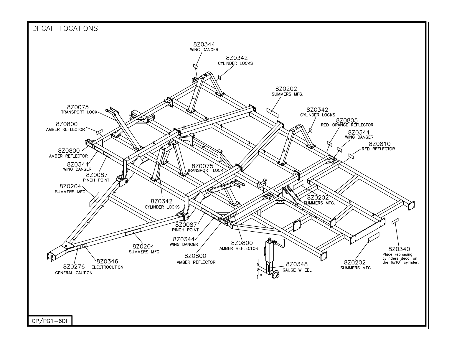
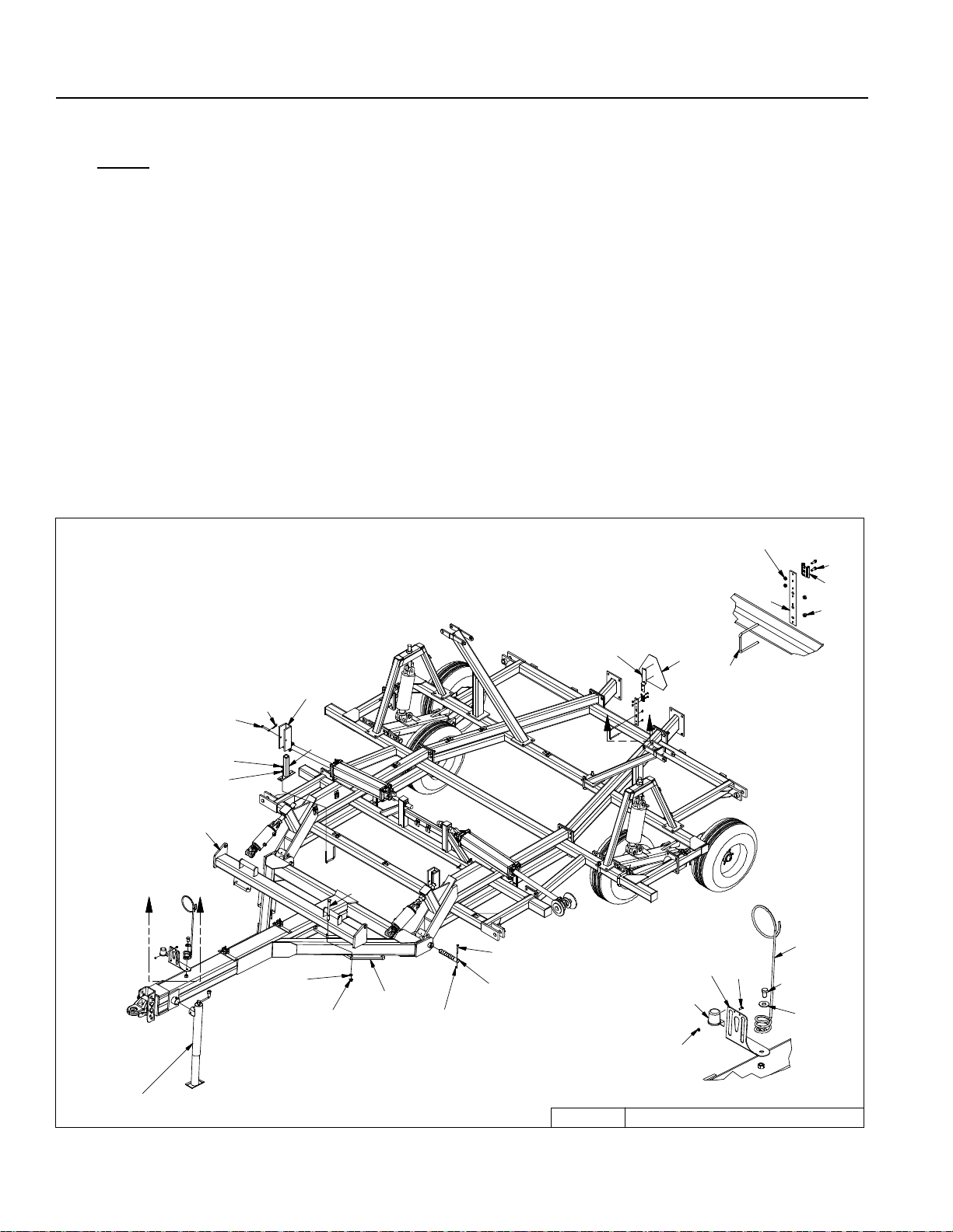
SECTION 2 – DECALS/OPTIONS
1. Install danger, warning, and caution decals.
– Part numbers can be found on lower right hand corner of each decal. Match this number with
number on decal location drawing on Page 1-6.
– The drawing gives approximate locations of decals. Decals must be clearly visible.
– Order replacement decals if any are damaged.
2. Install reectors.
– Amber reectors are part # 8Z0800, these should be placed on front corners and sides of
machine in transport position.
– Red-orange reectors are part # 8Z0805, these should be placed on outside back of machine
in transport position.
– Red reectors are part # 8Z0810, these should be placed on outside back of machine in
transport position.
3. Install Safety Light Kit, see Page 6-16 for mounting layout.
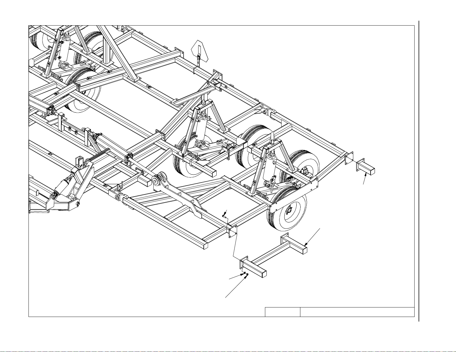
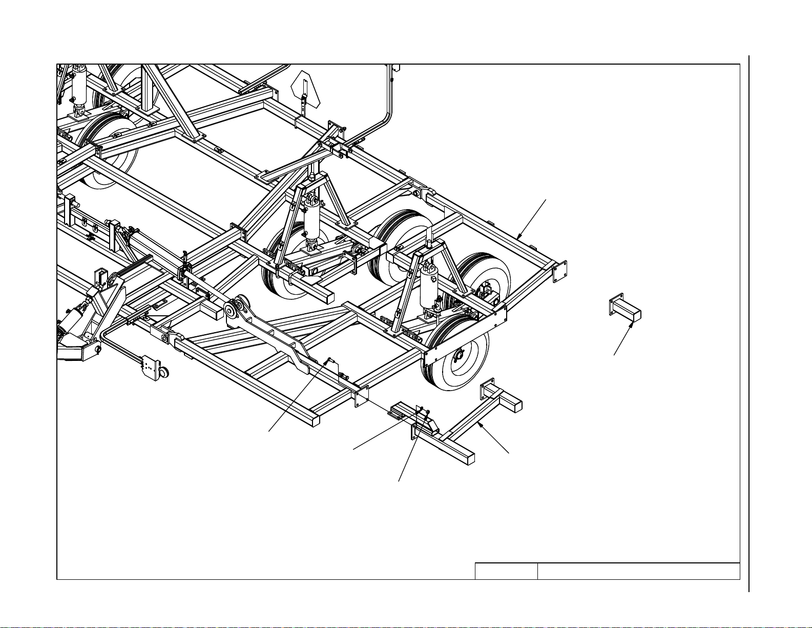
OPTIONS
See Parts Section for layout of Optional Mounted Harrows, Caster Wheel and Rear Hitch.
2-54
Page 67

SECTION 3 – CHISEL PLOW OPERATION
CHISEL PLOW OPERATION SAFETY
1. READ AND UNDERSTAND Operator’s Manual before using machine. Review at least annually thereafter.
2. VERIFY that all safety devices and shields are in place before using machine.
3. KEEP hands, feet, hair and clothing away from moving parts.
4. STOP engine, place all controls in neutral, set parking brake, remove ignition key and wait
for all moving parts to stop before servicing, adjusting, maintaining or unplugging.
5. BE CAREFUL when working around high pressure hydraulic system.
6. A LWAYS make sure that pressure is relieved from hydraulic circuits before servicing or disconnecting from tractor.
7. DO NOT ALLOW RIDERS.
8. USE EXTREME CARE when making adjustments.
9. KEEP CHILDREN AWAY from machinery at all times.
10. NEVER ALLOW anyone to walk or work under a raised piece of equipment without installing
cylinder and transport locks.
STEPS PRIOR TO OPERATION
1. COMPLETE WARRANTY REGISTRATION CARD
A. Complete and return WARRANTY REGISTRATION CARD located at the beginning of this
manual. RETURNING CARD ENTITLES YOU TO A FREE GIFT.
B. Complete the OWNER REGISTER also located at the beginning of this manual (Serial
Number is located at the front of the hitch). OWNER REGISTER INFORMATION MAY
BE NEEDED WHEN ORDERING PARTS.
2. VERIFY TRACTOR REQUIREMENTS
A. Recommended engine horsepower is 8-11 per foot.
NOTE: It may be necessary to reduce tillage depth, change tillage tools or perform multiple
passes if below this horsepower range.
3. FINAL CHECK
A. After receiving or assembling your Chisel Plow, it is a good practice to double check the
entire machine so all fasteners are securely tightened.
B. Make sure all grease ttings are in place and greased properly.
C. Inate tires to recommended ination pressure (see page 5-2) and check that wheel bolts
are tight.
3-1
Page 68

SECTION 3 – CHISEL PLOW OPERATION
INITIAL HOOKUP
1. Make tractor to hitch connection with locking draw pin and safety chain.
2. Retract jack and rotate into storage position. Connect Safety Light Kit to 7 pin receptacle.
3. Plug wing lift hoses into desired tractor outlet. Insure that tips and couplers are CLEAN.
4. Plug depth control hoses into desired tractor outlet.
5. Park tractor and chisel plow on a level surface.
6. Remove transport lock pins on wings.
DANGER
FRAME PINCH POINT HAZARD
KEEP AWAY
To prevent serious injury or death from crushing:
• Stay away from frame hinge area when folding
wings.
• Keep others away.
• Do not fold wings when bystanders are present.
8Z0087
WARNING
REMOVE TRANSPORT LOCK(S) BEFORE LOWERING MACHINE.
IF LOCK(S) DO NOT REMOVE FREELY, INSURE THAT
CYLINDERS ARE COMPLETELY FILLED WITH HYDRAULIC
FLUID AND ARE SUPPORTING THE LOAD TO BE LOWERED.
8Z0075
3-2
Page 69

SECTION 3 – CHISEL PLOW OPERATION
7. Lower wings with caution. Do not raise or lower the wings when moving. Operate tractor hydraulics
from operator station only. Do not allow any one near Chisel Plow when wings are raised
or lowered.
DANGER
TO AVOID INJURY OR DEATH
STAND CLEAR OF MACHINE
WHEN WINGS ARE BEING
RAISED AND LOWERED.
MECHANICAL OR HYDRAULIC FAILURE CAN ALLOW
WINGS TO FALL RAPIDLY.
8Z0344
IMPORTANT
A one-way restrictor is installed in wing lowering hydraulic circuit. This has been done to
reduce chance of wing free fall. Do not remove this restrictor.
3-3
Page 70

SECTION 3 – CHISEL PLOW OPERATION
8. Fully extend depth control cylinders and maintain hydraulic pressure for 30 seconds to insure that
all air has been purged from the system.
32’
to 44’
Only
NOTE: This machine has rephasing style depth control cylinders. When cylinders are
fully extended, oil will bypass through a rephasing slot on each cylinder in order to
equalize the system.
9. Remove depth control cylinder transport locks.
WARNING
REMOVE TRANSPORT LOCK(S) BEFORE LOWERING MACHINE.
IF LOCK(S) DO NOT REMOVE FREELY, INSURE THAT
CYLINDERS ARE COMPLETELY FILLED WITH HYDRAULIC
FLUID AND ARE SUPPORTING THE LOAD TO BE LOWERED.
8Z0075
3-4
Page 71

SECTION 3 – CHISEL PLOW OPERATION
9. (Continued) – Store transport locks on holders.
10. Become familiar with single point depth control. Control can be found on 6 x 10 cylinder located
on lefthand wing. A hairpin clip is used to hold plunger in desired location.
3-5
Page 72

SECTION 3 – CHISEL PLOW OPERATION
FIELD OPERATION
1. Rephase cylinders before starting eld operation.
IMPORTANT
TO REPHASE CYLINDERS, RAISE
MACHINE AND MAINTAIN HYDRAULIC
PRESSURE TEN SECONDS AFTER
CYLINDERS ARE FULLY EXTENDED.
QUICKLY RETRACT CYLINDERS AT
LEAST 1/2”. REPHASING SHOULD BE
DONE EVERY HOUR OF OPERATION TO
MAINTAIN UNIFORM TILLAGE DEPTH.
2. Choose a at spot in a eld to set tillage depth and level chisel plow.
8Z0340
IMPORTANT!
The operator is responsible for adjusting machine since machine does not come “Field
Ready” from factory.
3. Determine desired tillage depth by working test strips within the eld.
NOTE: Optimum performance of machine is achieved by tilling at a depth and moving at a
speed that does not go beyond limit of trip assemblies. This limit is exceeded if connecting
bolt (shown in the following drawing) continually rides above trip assembly cap.
3-6
Page 73

SECTION 3 – CHISEL PLOW OPERATION
3. (Continued) – Trip Assembly Limit
NOTE: Increased draft will occur if connecting bolt continually rides above trip assembly
cap. This will consume horsepower as well as reduce life of trip assembly components.
4. After determining desired tillage depth, set depth control plunger accordingly. Standard plunger
hole spacing gives 5/16” cylinder stroke adjustment. By rotating plunger 90 degrees, a half step
adjustment is achieved.
3-7
Page 74

SECTION 3 – CHISEL PLOW OPERATION
5. Leveling chisel plow from side to side. Stop tractor with machine in the ground. Check depth of
tillage on the left wing, center, and right wing. If leveling is necessary, use wrenches provided to
adjust eyebolts on cylinder attachments located at rear of chisel plow.
*NOTE: Insure that cylinder attach holes are aligned when eyebolts are tightened.
IMPORTANT!
Pressure must be removed from cylinders before adjusting eyebolts. Rest chisel plow on
top of the ground, shut tractor off and relieve pressure by cycling remote lever.
One turn of 1-1/2” NC Cylinder Attach Eyebolt Nut changes chisel height 3/8”. One inch of cylinder
stroke moves chisel plow height over 2 inches. Therefore, it may only be necessary to move eyebolts
a small amount to attain correct adjustment of each section.
3-8
Page 75

SECTION 3 – CHISEL PLOW OPERATION
NOTE: It is best to check levelness of chisel plow after each adjustment by working test
strips within the eld.
6. Leveling machine from front to back.
16’ - 30’ Narrow: With chisel plow still in the ground, check depth of tillage in the front and the
back of machine. Level with hitch tilt cylinders.
32’ Standard - 44’: With chisel plow still in the ground, check depth of tillage in the front and the
back of machine. If leveling is necessary, use wrenches provided to adjust eyebolt on front wheel
assembly up or down.
The front center lift arm has two cylinder attach locations. If chisel plow has a full set of mounted
harrows or if rear of machine is low in transport position, use rear cylinder attach hole. Connecting front center cylinder to rear hole will lower front end of chisel plow in transport position.
IMPORTANT!
Pressure must be removed from cylinders before adjusting eyebolts. Rest chisel plow on
top of the ground. Shut tractor off and relieve pressure by cycling remote lever.
3-9
Page 76

SECTION 3 – CHISEL PLOW OPERATION
7. Setting gauge wheels (32’ Standard-44’). After depth has been established and chisel plow has
been leveled, operator must set gauge wheels. Stop tractor with chisel plow in the ground. Adjust
crank assembly until wheel rests on top of the ground. Set bolts are installed on each gauge wheel
assembly. Adjust set bolts so gauge wheel depth can still be changed but rotation of assembly is
limited. If running at a consistent depth, set bolts can be securely tightened to lock gauge wheels.
IMPORTANT!
Gauge wheels are only intended to stabilize the wings. They should not be used to support entire weight of wings. Tough soil conditions may create “suction” on the front of the
chisel plow. As long as the machine is not operated beyond trip assembly limit (see page
3-7), gauge wheels are being used properly. Failure to follow these guidelines may result
in machine damage.
A depth decal is attached to the axle holder to help operator in setting gauge wheels.
3-10
Page 77

SECTION 3 – CHISEL PLOW OPERATION
8. Operation “Tips”
32’ - 44’
– The 5 solid lift arms on this machine are designed to prevent skewing from side to side.
To avoid damage to lift arms and wheel assemblies, do not take sharp corners with
chisel plow in the ground.
32’ - 44’
– Floating hitch machines are designed to follow ground contours. The Summers chisel
plow has a short wheel base in eld position that allows it to smoothly follow through
ditches and gullies. This machine will also follow deep furrows in the eld. The opera-
tor may want to till through deep furrows at an angle to maintain a more uniform tillage
depth.
– Rephase cylinders every hour. If the chisel plow is raised and lowered only a small
ALL
amount during operation, cylinders will not remain in phase. Since each section is supported by individual cylinders, it is important to keep these cylinders in phase in order
to maintain uniform tillage depth (See Page 3-6).
NOTE: Sweeps that are 14” and less can be used without trimming. Wider sweeps may
need to be trimmed by tires and/or walking tandems.
TRANSPORTING
1. Park tractor and chisel plow on level surface with depth control cylinders fully raised.
2. Raise wings with caution. Operate tractor hydraulics from operator station only.
DANGER
TO AVOID INJURY OR DEATH
STAND CLEAR OF MACHINE
WHEN WINGS ARE BEING
RAISED AND LOWERED.
MECHANICAL OR HYDRAULIC FAILURE CAN ALLOW
WINGS TO FALL RAPIDLY.
8Z0344
3. Install transport lock pins on
wings and cylinder locks on
depth control cylinders.
TO AVOID INJURY
WARNING
3-11
INSTALL CYLINDER
LOCKS BEFORE
TRANSPORTING OR
SERVICING MACHINE.
8Z0342
Page 78

SECTION 3 – CHISEL PLOW OPERATION
4. Use a safety chain between tractor drawbar and chisel plow hitch when transporting.
5. Only tow at a safe speed – 20 MPH MAXIMUM. Use caution when making corners or meet-
ing trafc.
6. Follow all local laws governing transporting of farm machinery.
7. Be aware of and comply with all height and width transport requirements. (See specications page 5-2).
8. Stay clear of overhead lines.
DANGER
TO AVOID INJURY OR DEATH
DO NOT CONTACT
ELECTRICAL LINES.
9. Avoid sharp turns on hard surfaces. Solid mounted lift arms may cause wheel assemblies
to scuff. Damage to tires and machine could occur.
10. Frequently check for trafc from rear, especially during turns.
UNHOOKING CHISEL PLOW FROM TRACTOR
1. Lower machine and relieve hydraulic pressure from cylinders before disconnecting from
tractor.
2. Disconnect hydraulics and Safety Light Kit wiring harness.
3. Rotate jack into standing position and extend jack.
8Z0346
4. Block tires to prevent movement of machine after unhooking.
5. Remove draw pin and safety chain.
3-12
Page 79

SECTION 4 – MAINTENANCE
MAINTENANCE SAFETY
1. STOP engine, place all controls in neutral, set parking brake, remove ignition key and wait
for all moving parts to stop before servicing, adjusting or maintaining.
2. BE CAREFUL when working around high pressure hydraulic system.
3. ALWAYS make sure that pressure is relieved from hydraulic circuits before servicing or
disconnecting from tractor.
4. USE EXTREME CARE when making adjustments.
5. KEEP CHILDREN AWAY from machinery at all times.
6. NEVER ALLOW anyone to walk or work under a raised piece of equipment without install-
ing cylinder and transport locks.
MAINTENANCE FOR AFTER THE FIRST DAY AND WEEK OF OPERATION
1. Grease lift arms, walking tandem assemblies, and hitch pivot. (There are a total of 12 daily
grease zerks).
2. Check all hydraulic components for leaks daily.
3. Check tightness of all wheel bolts daily.
4. Check tightness of wheel bearings (See
Page 6-20).
5. Check tightness of the following bolts on
the trip assemblies.
6. Check tightness of all hardware. Pay
special attention to the hitch bolts and
all pivot retaining bolts.
4-1
Page 80

DAILY MAINTENANCE
1. Grease lift arms, walking tandem assemblies, and hitch pivot.
2. Check all hydraulic components for leaks.
3. Check tightness of all wheel bolts.
PERIODIC MAINTENANCE
SECTION 4 – MAINTENANCE
1. Repack wheel bearings and check tightness (See Page 6-20).
2. Check tire air pressure (See specication page 5-2).
3. Check tightness of trip assembly hardware as explained under “Maintenance for after the
4. Check tightness of all hardware. Pay special attention to the hitch bolts and all pivot retain-
5. Check chisel plow for damaged or worn parts. Replace as needed.
STORAGE
1. Clean and remove all excessive dirt and grease from chisel plow.
2. Grease all zerks.
3. To prevent rusting, repaint any areas that have been worn, chipped or scratched.
4. Retract cylinders when possible. Apply grease* to any exposed part of cylinder shafts.
rst day and week of operation” (Page 4-1).
ing bolts.
*NOTE: Before returning chisel plow into service, all grease must be removed from cylinder shafts to prevent damage to seals.
4-2
Page 81

SECTION 5 – TROUBLESHOOTING
PROBLEM CAUSE CORRECTION
1. Not tilling level. A. Depth control cylinders out
of phase.
B. Eyebolts not adjusted prop-
erly.
C. Gauge wheels not adjusted
properly.
D. Hard Soils conditions. Use different tillage tool or perform
2. Not pulling straight. A. Chisel plow not tilling level. See “Not tilling level” above.
3. Inconsistent tillage
depth.
4. Plugging. A. Working in extremely heavy
5. Poor penetration. A. Machine not running level
6. Depth control cylinders
not working properly.
7. Wing lift cylinders move
too fast.
A. Excessive travel speed. Reduce speed.
B. Hard soil conditions. Use different tillage tool or perform
C. Deep furrows. Travel across eld furrows at an
trash.
B. Tillage tool (spike, sweep,
etc.) causing plugging.
front to back.
B. Gauge wheels adjusted
improperly.
C. Hard soil conditions. Use different tillage tool.
A. Depth control cylinders out
of phase.
B. Hydraulic hoses not con-
nected properly or faulty
hyd. coupler.
C. Tractor hydraulics not set
properly.
A. One way restrictor(s) not
installed properly.
B. Tractor hydraulics not set
properly.
Rephase cylinders. See page 3-6.
Adjust with wrenches provided.
See Pages 3-8 and 3-9.
Adjust gauge wheels so they ride
freely on top of the ground.
multiple passes, starting at less
depth.
multiple passes, starting at less
depth.
angle.
If equipped with mounted harrows,
reduce aggressiveness of harrows
or lock harrows in the up position.
Change type of tool. Make sure
twisted spikes are not throwing
soil towards wheels.
Adjust eyebolts on front center
wheel assembly.
Adjust gauge wheels so they ride
freely on top of the ground.
Rephase cylinders by fully extending and holding tractor remote
lever for 30 seconds.
Reconnect hydraulic hoses or
replace hydraulic coupler.
Adjust tractor hydraulic ow rate to
maximum on Depth Control Circuit.
Check resistor(s) (PN 8J7116). Arrow must point towards cylinder.
Reduce ow rate to Wing Lift Cylinder Circuit.
5-1
Page 82

SECTION 5 – TROUBLESHOOTING
WIDTH, HEIGHT, WEIGHT, LENGTH
APPROX. APPROX WEIGHT WEIGHT LENGTH
SIZE TRANSPORT TRANSPORT STANDARD W/3BAR 104 W/3BAR 106 W/3 BAR
WIDTH HEIGHT WEIGHT HARROWS HARROWS 104 OR 106
16’ 15’9” 8’ 8,737 9,641 9,714 30’3”
20’ 20’ 8’ 9,601 10,623 10,771 30’3”
24’ 15’10” 11’4” 14,200 15,808 15,888 30’3”
26’ 15’10” 11’11” 14,500 16,160 16,250 30’3”
28’ 15’10” 12’11” 14,900 16,608 16,708 30’3”
30’ 15’10” 13’4” 15,280 17,038 17,148 30’3”
32’ 19’6” 12’6” 13,909 15,403 15,535 33’
34’ 19’6” 13’5” 14,203 15,440 15,580 33’
36’ 19’6” 14’4” 14,639 15,500 15,648 33’
38’ 19’6” 15’3” 15,004 16,867 17,023 33’
40’ 19’6” 16’2” 15,974 18,122 18,288 33’
42’ 19’6” 17’1” 16,268 18,170 18,344 33’
44’ 19’6” 18’0” 16,704 18,943 19,125 33’
TIRE SPECIFICATIONS
LOCATION TIRE SIZE PLY RATING INFLATION PRESSURE (PSI)
STANDARD
CENTER/WINGS
OPTIONAL
CENTER/WINGS
* To increase penetration depth, ination pressure can be reduced by up to 33% on rear tires and 25% on front center
tires.
11L x 15 LRF 85*
12.5L x 15 LRF 90*
5-2
Page 83

SECTION 5 – TROUBLESHOOTING
PROPER BOLT USE
DO NOT use these values if a different torque value or tightening procedure is given for a specic
application. Torque values listed are for general use only. Check tightness of fasteners periodi-
cally.
BOLT SIZE WRENCH SIZE GRADE 5 GRADE 8
ft-lbs N • m ft-lbs N • m
1/4” 7/16” or 3/8” 7 9.5 12 17
5/16” 1/2” 15 20 25 34
3/8” 9/16” 30 41 45 61
7/16” 5/8” or 11/16” 45 61 70 95
1/2” 3/4” 70 95 105 142
9/16” wheel bolts 7/8” 170 231
5/8” 15/16” 170 231 210 285
5/8” wheel nuts 1-1/16” 240 325
3/4” 1-1/16”* or 1-1/8” 250 339 375 509
7/8” 1-5/16” 350 475 600 814
1” 1-1/2” 450 610 880 1193
1-1/4” 1-7/8” 500 678
1-1/2” 2-1/4” 570 773
2” 3-1/8” 1200 1627
*Nylon Lock Nut 3/8/12 TILLAGE
5-3
Page 84

SECTION 5 – TROUBLESHOOTING
NOTES
5-4
Page 85

SECTION 6 – PARTS
BRING YOUR OWNER REGISTER INFORMATION LOCATED AT THE
BEGINNING OF THIS MANUAL WHEN ORDERING PARTS (SERIAL
NUMBER IS LOCATED BY THE HITCH PIECE).
6-1
Page 86

6-2
16' & 20' CENTER
8CC5018
8K5515
3/4 X 4 X 6"
8X0112
3/4X2-1/4"
8X0306
3/4" LW
8T4030 - 16' REAR
8CC4028 - 20' REAR (SHOWN)
SECTION 6 – PARTS
8X0260
3/4" N
8X0306
3/4" LW
8T4015
8X0260
3/4" N
8CC5230
CENTER2/15/2011 9T2012H.iam/
Page 87

16’ & 20’
6-3
8CC4000
8X0260
3/4" N
8X0306
3/4" LW
8K1640
7/16" LNUT
8X0234
3/4 X 4-1/16 X 6"
q
8X0044
7/16" X 3-1/2"
8T4101
8K5515
8X0285
1 1/2" N
8X0044
7/16" X 3-1/2"
8T3640
8X0234
7/16" LNUT
8X0286
1 1/2" JN
8T3620
8D9108
8K9106
8T1060
8T4224
8X0044
7/16" X 3-1/2"
8T4166
SECTION 6 – PARTS
8A1156
3/8 X 4-1/16 X 5"
8T4190
8X0072
1/2" X 3-3/4"
8K1100
8CC4140
8X0203
3/8" FN
8X0242
NY-LOCK 1/2" N
9T2012H/
CENTER W-CYL.ATTCH3/19/2014
8R6914
8K7033
11L LRF
Page 88

24', 26', 28' & 30' NARROW CENTER
6-4
3/4X2-1/4"
8CC5062
8X0112
8X0260
8K5515
3/4 X 4 X 6"
3/4" N
8X0306
3/4" LW
8CC5070
SECTION 6 – PARTS
8T4010
8CC5230
8X0306
3/4" LW
8X0260
3/4" N
9T2412N.iam/
CENTERS2/16/2011
Page 89

6-5
24', 26', 28' & 30' NARROW CYLINDER ATTACHMENT
8T4224
8X0286
1 1/2" JN
q
SECTION 6 – PARTS
8X0285
1 1/2" N
8X0306
3/4" LW
8X0260
3/4" N
8K5515
3/4 X 4-1/16 X 6"
9T2412N.iam/
8K1755
CENTER W-CYL.ATTCH3/19/2014
Page 90

8D9524
8T1050
8CC4325
8K5515
3/4 X 4 X 6"
24', 26', 28' & 30' NARROW
8X0260
3/4" N
8X0306
3/4" LW
8T1055
SECTION 6 – PARTS
8D9108
1/4 X 2" RP
6-6
8T3300
8L0252
DETAIL A
8X0316
1" FW
8L0252
8T3800
8X0282
8T3800
8T3640
8X0234
7/16" LNUT
8K5515
3/4 X 4 X 6"
DETAIL B
A
8X0044
7/16" X 3-1/2"
8X0306
3/4" LW
8T4100
8K9106
8X0260
3/4" N
8D9108
1/4 X 2" RP
8CC4140
8T4166
B
2/9/2012 9T2412N.iam/
8K9106
8A1156
3/8 X 4-1/16 X 5"
8T4190
1/2" X 3-3/4"
8X0234
7/16" LNUT
CENTER W-TRANSPORT
8X0203
3/8" FN
8X0242
NY-LOCK 1/2" N
8K1100
8X0072
8K7033
Page 91

q
24', 26', 28' & 30' NARROW WING
8X0286
1 1/2" JN
6-7
7/16" X 3-1/2"
8T3600
8X0234
7/16" LNUT
8T4035 (24', 26', 28', 30' LEFT)
8T4037 (24', 26', 28', 30' RIGHT)
8C6015
8X0044
8X0260
3/4" N
8X0306
3/4" LW
8K5515
3/4 X 4-1/16 X 6"
8K1755
8X0285
1 1/2" N
8T4224
SECTION 6 – PARTS
9T2412N.iam/
WING3/19/2014
Page 92

24', 26', 28' & 30' NARROW WING
8X0242
8T4175
8L0300
NY-LOCK 1/2" N
6-8
1/2" X 4-1/2"
8X0074
8T4174
8S0660
8X0077
1/2" X 7-1/2"
8X0242
NY-LOCK 1/2" N
8CC4140
8X0240
1/2" N
8T4176 - LEFT
8T4177 - RGHT (SHOWN)
A
8T4168
8T4100
8K1100
8X0303
1/2" LW
B
8S0660
SECTION 6 – PARTS
DETAI L B
8K7033
8R6914
DETAI L A
8K4178 - LEFT
8K4179 - RGHT (SHOWN)
WING-TRANSPORT2/21/2013 9T2412N.iam/
Page 93

SECTION 6 – PARTS SECTION 6 – PARTS
6-9
Page 94

SECTION 6 – PARTS (32’-38’) SECTION 6 – PARTS (32’-38’)
6-10
Page 95

SECTION 6 – PARTS (40’-44’)
6-11
Page 96

SECTION 6 – PARTS (16’-30’ NARROW)
DEPTH CONTROL HYDRAULICS
3/4"-16ORB X 10 JIC(M)
8N6570
3/4" X 570"
8T1008
PLASTIC
PLUNGER
REPAIR
KIT
8T1010
BOLT ON
POPPET
ASSY
8J5520
8D3212
8T1015
HPC
MALE TIP, 3/4"-16ORB ISO
TOP VIEW
8J5520
8J5520
3/4"-16ORB X 10 JIC(M)
3/4"-16ORB X 10 JIC(M)
8T1060
6.0" X 10"
8T1006
PLUNGER
8J5510
3/4"-16ORB X 6 JIC(M)
8K9106
CYL PIN
8D9108
ROLL PIN
8N4228
1/2" X 228"
16' & 20' MACHINES
8D3212
MALE TIP, 3/4"-16ORB ISO
8N4546
1/2" X 546"
3/4"-16ORB X 10 JIC(M) 90° ADP
8T1055
5.5" X 10"
8J6020
16' - 30' NARROW CHISEL
HYDRAULIC HITCH
8J5300
#6 JIC(M) TEE
#6 JIC(F-SW) X #6 JIC(M) 90° ADP
8J5700
3/4" ORB X #6 JI C(M)
8D3212
3/4" ORB TIP ISO
8J5510
8CC4010
8C1710
3/8 X 8 X 9"
8W1398
8N3150
2X
8X0202
3/8" LN
8X0120
3/4" X 9"
8X0306
3/4" LW
8N3048
2X
8N3060
8X0260
3/4" N
8CC4012
3/4-16ORB X #6JIC(M) 90° ADP
8J6010
2X
DISKCHSL-CLTRCHSL/DEPCONHYD4/8/2010
8X0285
1 1/2" N
8P7250
8T2040
6-12
2/9/2012
9T2012H.iam/
16'-28' NRRW HYD HITCH
Page 97

DEPTH CONTROL HYDRAULICS
8D3212
MALE TIP, 3/4"-16ORB ISO
24'-28' NARROW
6-13
8J5520
3/4"-16ORB X 10 JIC(M)
8T1008
PLASTIC
PLUNGER
REPAIR
KIT
TOP VIEW
1/2" X 198"
3/4" HOSE CLAMP
8N6570
3/4" X 570"
8N4198
8T2990
SS BSHNG
8R6810
8J6020
8J6020
8J6020
8J6020
8J6020
3/4"-16ORB X 10 JIC(M) 90° ADP
3/4"-16ORB X 10 JIC(M) 90° ADP
3/4"-16ORB X 10 JIC(M) 90° ADP
3/4"-16ORB X 10 JIC(M) 90° ADP
3/4"-16ORB X 10 JIC(M) 90° ADP
8N4228
1/2" X 228"
8K9106
CYL PIN
8D9108
ROLL PIN
8G2285
NYL. TIE (GREEN)
8N3534
3/8" X 534"
8N4198
1/2" X 198"
CYLINDER PORTS
TOWARDS FRONT
OF MACHINE
SECTION 6 – PARTS (24’-30’ NARROW)
8T1010
BOLT ON
POPPET
ASSY
8T1060
8T1015
HPC
8J5520
8J5520
3/4"-16ORB X 10 JIC(M)
3/4"-16ORB X 10 JIC(M)
6.0" X 10"
8T1055
5.5" X 10"
8T1050
5.0" X 10"
3/4"-16ORB X 6 JIC(M) 90° ADP
8T1045
4.5" X 10"
8J6010
DISKCHSL-CLTRCHSL/DEPCONHYD4/8/2010
Page 98

6-14
SECTION 6 – PARTS (32’-44’ NARROW)
Page 99

6-15
SECTION 6 – PARTS (32’-44’)
Page 100

6-16
SECTION 6 – PARTS (16’-44’)
 Loading...