

Page 1
ROCK PICKER MODEL 700
Rotary Rockpicker, Hyd. Direct Drive
ROCK PICKER MODEL 700
Operator’s
Manual
MODEL 700
IMPORTANT
THE OPERATOR IS RESPONSIBLE FOR ADJUSTING THE MACHINE SINCE MACHINE DOES
NOT COME “FIELD READY” FROM FACTORY.
See www.summersmfg.com for the latest version of all Summers Operator’s Manuals
SUMMERS MANUFACTURING CO., INC.
WEB SITE: www.summersmfg.com
MADDOCK, NORTH DAKOTA 58348 ........................................................ (701) 438-2855
DEVILS LAKE, NORTH DAKOTA 58301 ................................................... (701) 662-5391
8Z1102 © Summers Mfg. Co., Inc. 2013 Printed in USA
READ & UNDERSTAND OPERATOR’S MANUAL
BEFORE USING MACHINE.
CAUTION
Page 2

Warranty
Summers warrants only products of its manufacture against operational failure caused by defective materials or workmanship which
occur during normal use within 12 months from the date of purchase by the end user from Summers’ dealer.
Summers’ obligation is to replace free of charge any part of any product that Summers inspection shows to be defective excluding
transportation charges to Maddock, ND or Devils Lake, ND and return and also excluding all transportation costs from Summers’ dealer to
the dealer’s customer and all other costs such as removal and installation expense.
Summers shall not be liable for loss of time, manufacturing costs, labor, material, loss of prots, consequential damages, direct or
indirect, because of defective products whether due to rights arising under the contract of sale or independently thereof, and whether or not
such claim is based on contract, tort or warranty.
Written permission for any warranty claim return must be rst obtained from authorized Summers’ personnel. All returns must be
accompanied with a complete written explanation of claimed defects and the circumstances of operational failure.
Written warranty for all component parts used in the manufacture of Summers products is available upon request. Warranty of such
component parts will be determined by said component manufacturer upon their inspection of the claimed defective part.
This express warranty is the sole warranty of Summers. There are no warranties, which extend beyond the warranty herein expressly
set forth. The sales for products of Summers under any other warranty or guarantee express or implied is not authorized. This warranty
voids all previous issues.
SUMMERS MANUFACTURING CO. INC.
MADDOCK, NORTH DAKOTA 58348
DEVILS LAKE, NORTH DAKOTA 58301
2/95
Mathison’s 9/2013
Page 3
GENERAL INFORMATION
This book is composed of three basic sections: Safety, Operation and Parts.
The Operation Section provides information for proper operation and maintenance of your Summers
Rockpicker. The Parts Section provides a complete parts breakdown for the Model 700 Rockpicker.
Reference to “Right” and “Left” in this book is determined when the machine is viewed from the rear.
Parts are referenced in each drawing with the Summers Manufacturing Part Number. Use this Part Number
when ordering replacement parts from your Summers dealer.
It is the policy of this company to improve its products whenever possible and practical to do so. We reserve
the right to make changes or improvements in the design or construction of parts at any time without incurring
the obligation to install such changes on products previously delivered.
Summers Manufacturing Company, Inc. strongly recommends that each Rockpicker Operator READ
and UNDERSTAND the Operator’s Manual before using the machine. In addition, this Operator’s
Manual should be REVIEWED at least ANNUALLY thereafter.
CONTENTS
Section 1: SAFETY
Safety-Alert Symbol and General Safety Practices ........................................... 1-1
Safety Decals ......................................................................................1-2 – 1-3
Maintenance Safety .................................................................................... 1-4
Section 2: OPERATION and MAINTENANCE
Initial Set-Up .............................................................................................. 2-1
Hydraulic Requirements ................................................................................. 2-1
Electric Solenoid Lift Option .......................................................................... 2-2
Field Operation .............................................................................................. 2-3
Maintenance and Service ................................................................................ 2-3
Troubleshooting ............................................................................................. 2-4
Section 3: PARTS
Main Frame, Model 700 .................................................................................. 3-2
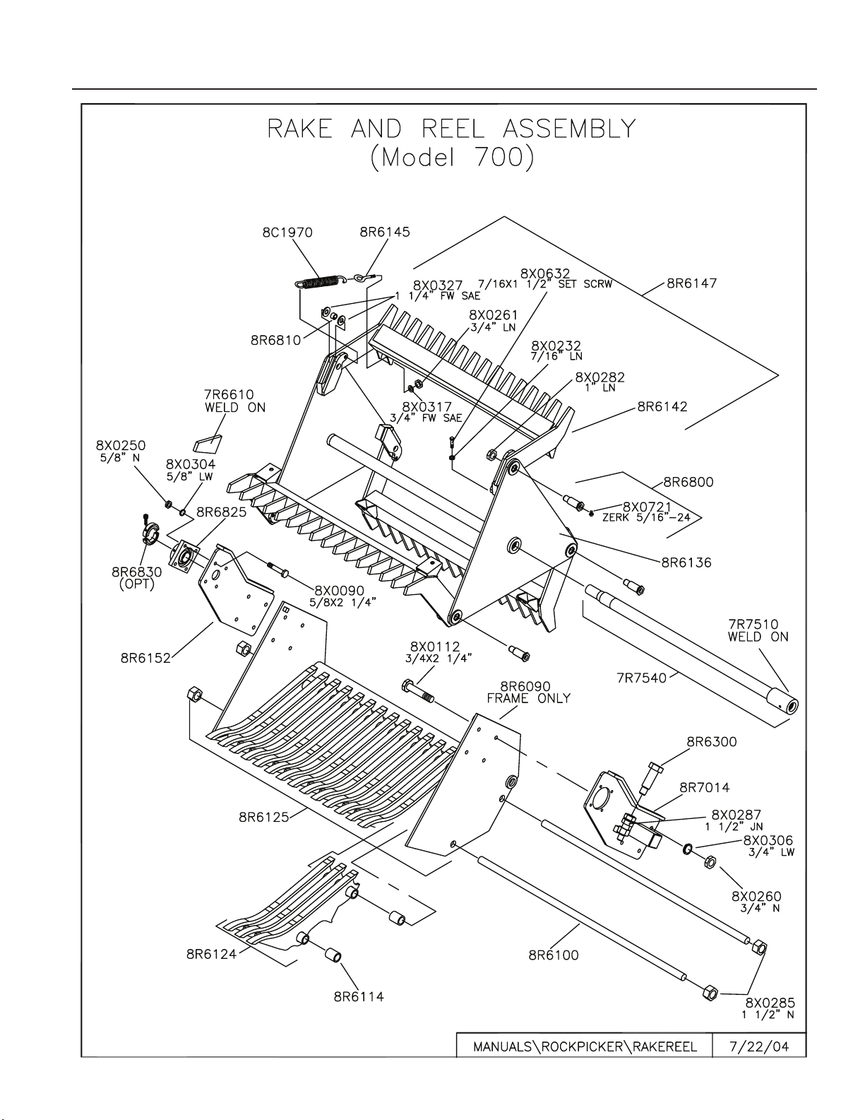
Rake and Reel Assembly, Model 700 ............................................................... 3-3
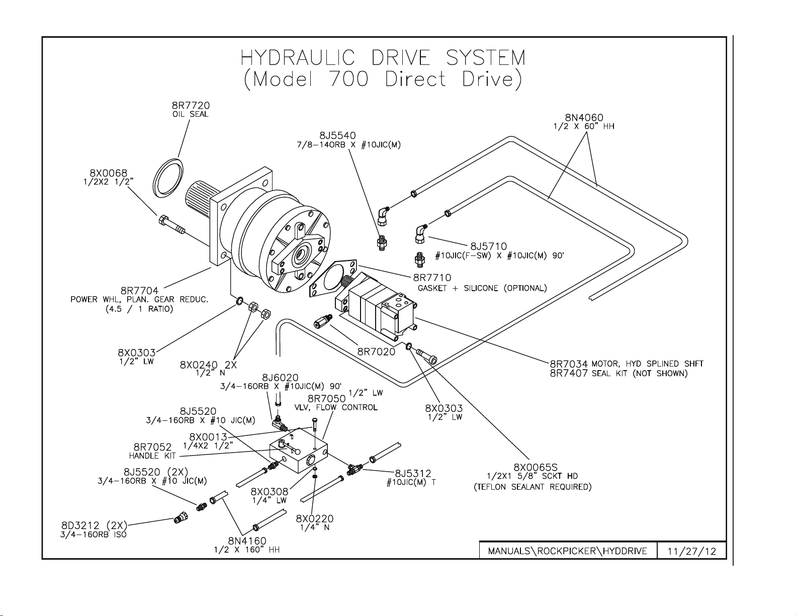
Drive System, Model 700 ................................................................................ 3-4
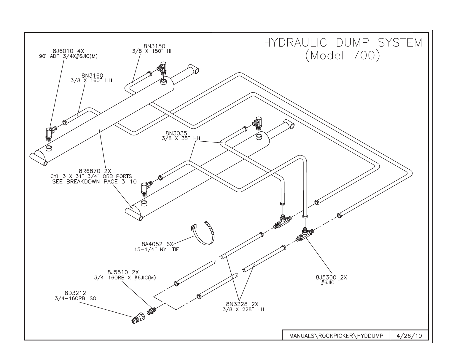
Hydraulic Dump System, Model 700 ............................................................... 3-5
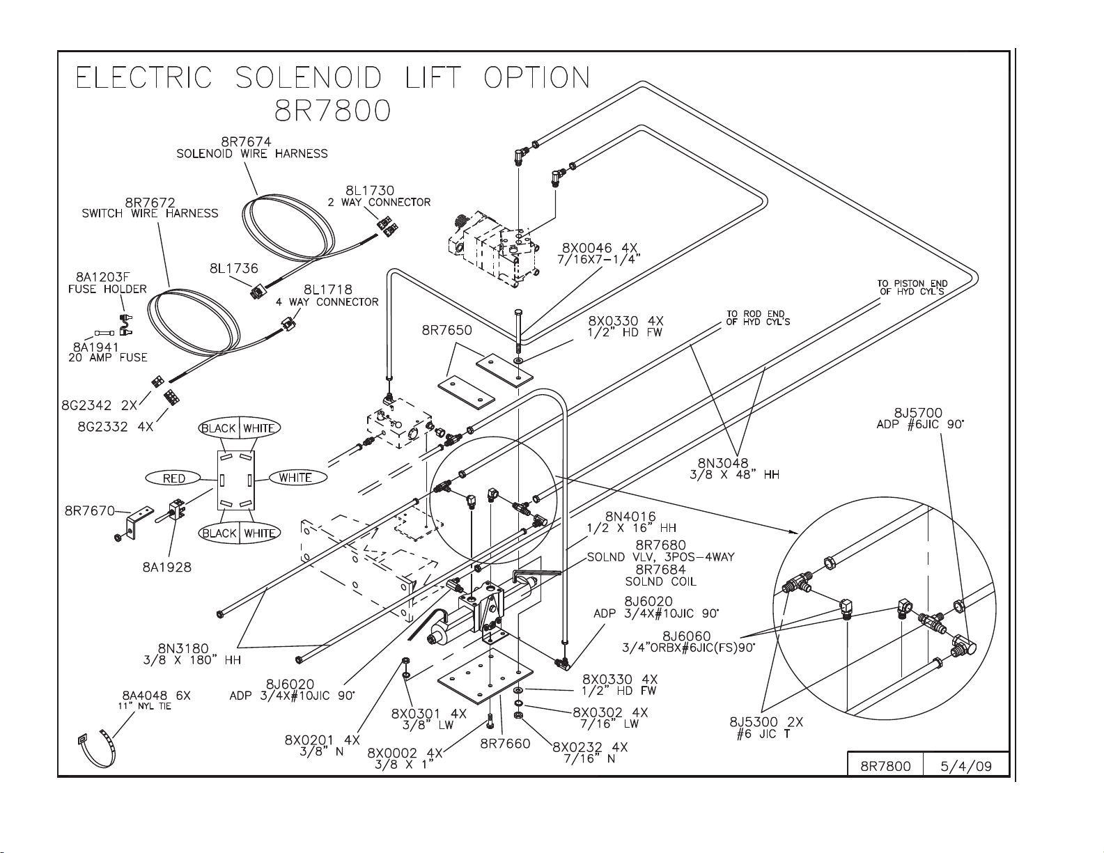
Electric Solenoid Lift Option .......................................................................... 3-6
Hydraulic Swing Hitch .................................................................................... 3-7
16.5L X 16.1 Tire ........................................................................................... 3-8
Hub and Axle Components .............................................................................. 3-9
Hydraulic Cylinder Breakdown...................................................................... 3-10
OWNER REGISTER
Name ____________________________________ Size _________________________________________
Address _________________________________ Serial Number _______________________________
City _____________________________________
State/Prov. ______________________________ Date Purchased ______________________________
Mail Code ________________________________ Dealer _______________________________________
i
Page 4

NOTES
ii
Page 5
SECTION 1 - SAFETY
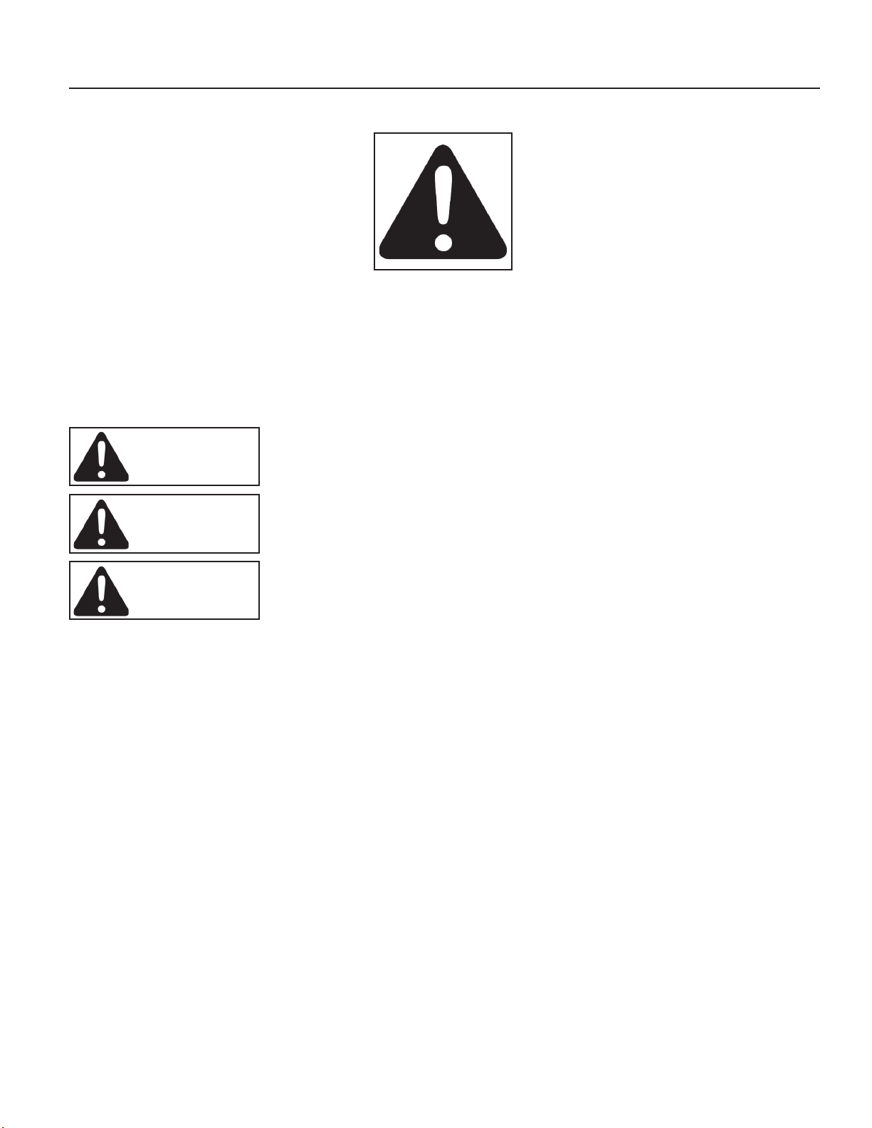
SAFETY-ALERT SYMBOL
This symbol is used to denote possible danger and
care should be taken to prevent bodily injury.
This symbol means:
ATTENTION! BECOME ALERT!
YOUR SAFETY IS INVOLVED!
Denition of each Signal Word used in conjunction with the Safety-Alert symbol.
indicates an imminently hazardous situation which, if not avoided, will result in death or
serious injury. This signal word is to limited to the most extreme situations.
DANGER
indicates a potentially hazardous situation which, if not avoided, could result in death
or serious injury.
WARNING
indicates a potentially hazardous situation which, if not avoided, may result in minor
or moderate injury. It may also be used to alert against unsafe practices.
CAUTION
GENERAL SAFETY PRACTICES
1. READ AND UNDERSTAND Operator’s Manual before using machine. Review at least annually thereafter.
2. VERIFY all safety devices and shields are in place before using machine.
3. KEEP hands, feet, hair and clothing away from moving parts.
4. STOP engine, place all controls in neutral, set parking brake, remove ignition key and wait for all moving
parts to stop before servicing, adjusting, maintaining or unplugging.
5. BE CAREFUL when working around high pressure hydraulic system.
6. DO NOT ALLOW RIDERS.
7. ALWAYS, make sure that pressure is relieved from hydraulic circuits before servicing or disconnecting from
tractor.
SAFETY DURING TRANSPORT
1. ONLY TOW at a safe speed. Use caution when making corners and meeting trafc.
2. USE transport lock and safety chain between tractor drawbar and rockpicker hitch when transporting on
public roads.
3. If rockpicker is towed on public roadways, hydraulically swing hitch so rockpicker trails directly behind tow-
ing vehicle. Install Transport Lock (8R7890) to prevent cylinder from retracting. The optional solid hitch can
be reversed so rockpicker trails directly behind towing vehicle.
4. COMPLY with local lighting, marking and oversize regulations when transporting on highways.
1-1
Page 6

SECTION 1 - SAFETY
SAFETY DECALS
1. KEEP SAFETY DECALS AND REFLECTORS CLEAN.
2. REPLACE missing or unreadable decals. New decals are available from your Summers
dealer by ordering correct part number (PN) located in lower right hand corner.
1. SUMMERS DECAL (PN 8Z0079)
2. PINCH POINT HAZARD DECAL (PN 8Z0087)
3. MODEL 700 ROCKPICKER DECAL (PN 8Z0158)
1-2
Page 7
SECTION 1 - SAFETY
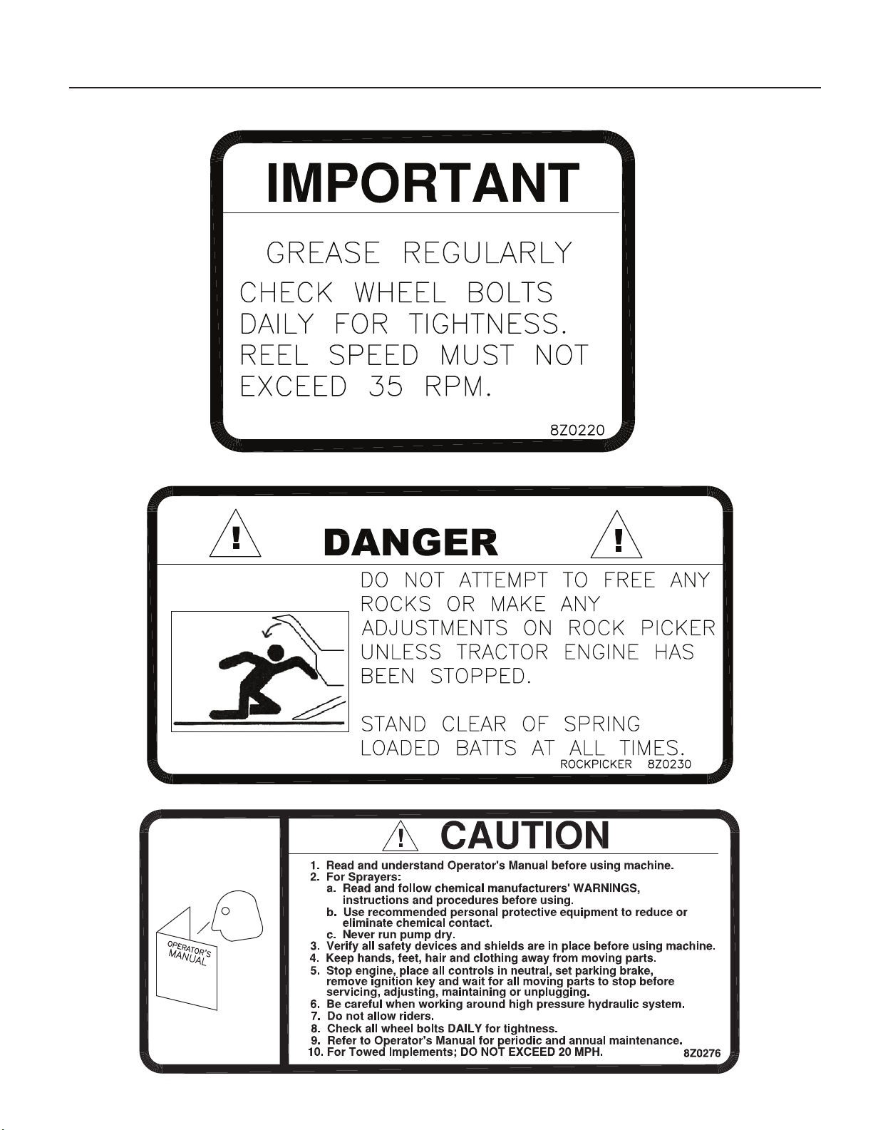
4. GENERAL INFORMATION DECAL (PN 8Z0220)
5. ROCKPICKER BATT WARNING DECAL (PN 8Z0230)
6. GENERAL CAUTION DECAL (PN 8Z0276)
1-3
Page 8
7. AMBER REFLECTOR (PN 8Z0800)
8. RED-ORANGE REFLECTOR (PN 8Z0805)
SECTION 1 - SAFETY
9. RED REFLECTOR (PN 8Z0810)
MAINTENANCE SAFETY
1. STOP engine, place all controls in neutral, set parking brake, remove ignition key and wait for all moving parts to
stop before servicing, adjusting or maintaining.
2. BE CAREFUL when working around high pressure hydraulic system.
3. ALWAY S make sure that pressure is relieved from hydraulic circuits before serving or disconnecting from tractor.
4. USE EXTREME CARE when making adjustments.
5. KEEP CHILDREN AWAY from machinery at all times.
6. STAND CLEAR of spring loaded batts at all times.
7. BE SAFE!
1-4
Page 9

SECTION 2 - OPERATION AND MAINTENANCE
INITIAL SETUP
HITCH AND SPINDLE SETUP
Install hitch with hydraulic cylinder on left side, attach hitch jack, safety chain, hydraulic hose stand and tip holder. Use
appropriate lifting device, hitch assembly weighs 410 lbs.
16.5L X 16.1 Tire: Attach receiver tube with plate (8R6206) to frame with tube on top. See Page 3-8.
NOTE: Remove safety transport lock pin located under rake AFTER hydraulic lines and cylinders have been lled with
oil.
BEFORE INITIAL OPERATION
1. After receiving your rockpicker, it is a good idea to double check the entire machine so that all bolts
are securely tightened. Recheck after rst 2 and 8 hours of operation.
2. Make sure all grease ttings are in place and greased properly.
3. Inate tires to recommended ination pressure (see spec. chart on page 2-3) and check wheel bolts
for tightness.
ROAD TOWING
If rockpicker is towed on public roadways, hydraulically swing hitch so rockpicker trails directly behind towing vehicle.
Install Transport Lock (8R7890) to prevent cylinder from retracting. Use transport lock and safety chain when transporting. Check wheel nuts before road transport, after rst 20 miles and every 60 miles thereafter. Also, before road transport
check wheel bearings for tightness and that wheel bearings are well greased.
I M P O R T A N T
HYDRAULIC REQUIREMENTS FOR MODEL 700 ROTARY ROCKPICKER
1. Closed center hydraulic systems usually work very well.
2. Open center hydraulic systems require sufcient oil ow to operate both the hydraulic reel motor and rake lift cylinders
simultaneously. Because open center systems vary greatly in performance, it is difcult to specify a minimum ow
requirement. For example, some open center systems work perfectly. On others, the reel will slow or even pause
while the rake is being raised. On still other open center systems, the rake can be raised only after stopping the
reel.
Therefore, when purchasing a rockpicker to be used on either a closed or open center hydraulic system, we strongly
recommend the tractor or tractors to be used on the rockpicker be tested for acceptable operation before the machine
is put into eld use. It is the responsibility of the dealer and purchaser to make this determination.
If tractor hydraulic pressure and ow are adequate but reel and rake cannot be operated simultaneously, installation
of the Electric Solenoid Lift Option will improve performance. See following page for option installation and operating
instructions.
2-1
Page 10
SECTION 2 - OPERATION AND MAINTENANCE
INSTALLATION INSTRUCTIONS FOR ELECTRIC SOLENOID LIFT OPTION
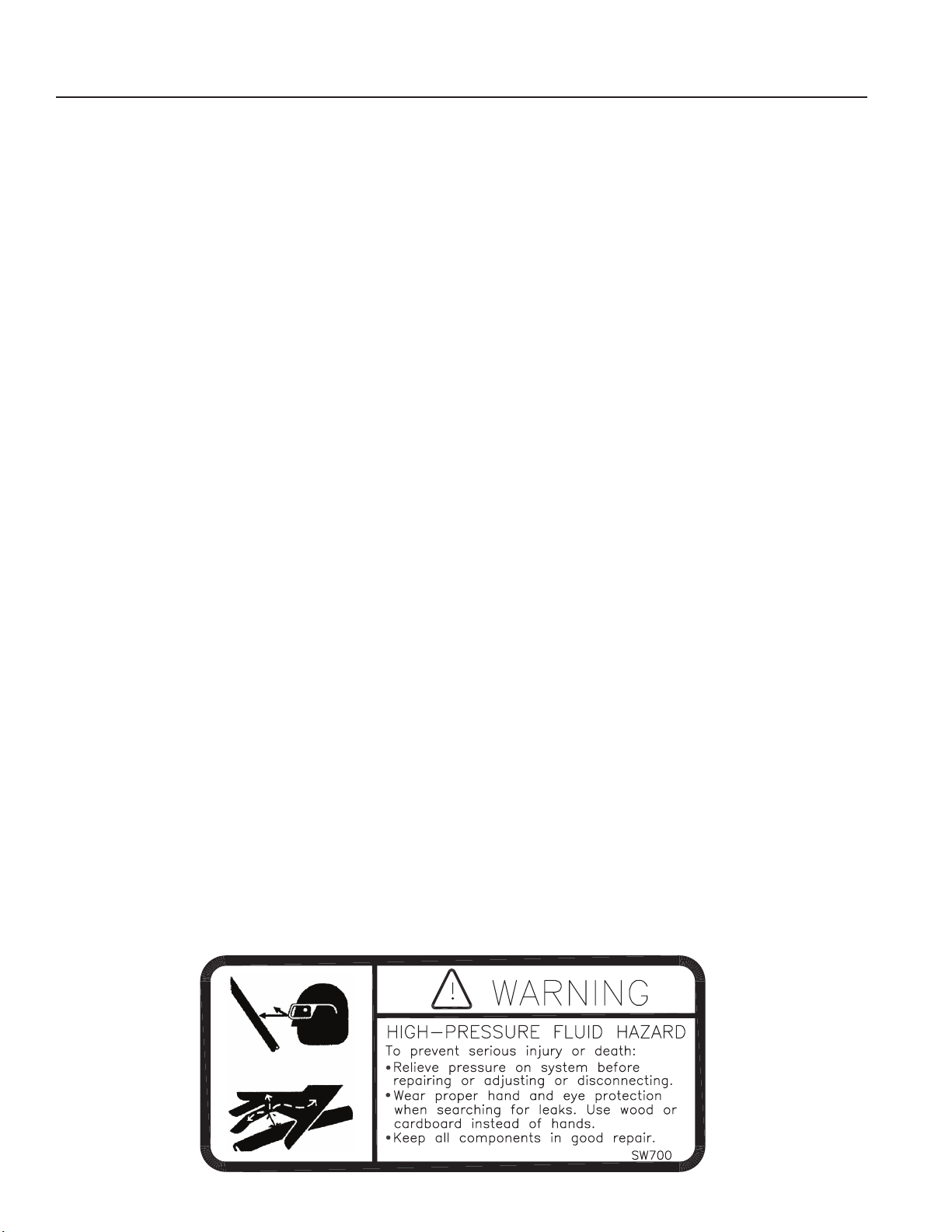
1. When installing an Electric Solenoid Lift Option refer to following instructions and see breakdown on page
3-6. Mounting the switch.
Mount switch to a secure support in a convenient location on the tractor. Route the red and white battery wires to a
12-volt battery. Attach the white battery wire to the NEGATIVE (-) terminal and the red battery wire to the POSITIVE
(+) battery terminal. A 20-amp in-line fuse is installed in the red battery wire to protect the system.
2. Mounting the solenoid valve (if not factory installed).
a. Disconnect the 1/2” X 60” hydraulic hose from the tee on the ow control valve on the rockpicker. Route hose
between rockpicker frame and connect tting on opposite side of the 1/2” X 16” hydraulic hose on the valve.
b. Remove two tees from top of solenoid valve.
c. Lift valve up between the rockpicker frame tubes directly behind the ow control valve and secure with two
plates and four 7/16” X 7-1/4” bolts, washers, lockwashers and nuts.
d. Connect the 1/2” X 16” hose on solenoid valve to tee on the ow control valve.
e. Replace ttings on top of solenoid valve removed in step “b”.
f. Remove two 3/8” X 228” hydraulic hoses from rockpicker and discard (tractor to cylinder tee hoses). Replace the
228” hoses with 48” and 180” hoses. Connect front of 48” and rear of 180” hoses to ttings on top of solenoid
valve as shown on page 3-6. Route the 180” hoses along reel drive hoses on rockpicker hitch.
g. Route wire harness from the valve to tractor along hydraulic hoses. Connect to switch assembly. Secure wire
harness with nylon ties.
OPERATING INSTRUCTIONS FOR ELECTRIC SOLENOID LIFT OPTION
1. Read installation instructions thoroughly before operating electric solenoid lift option.
CAUTION: Follow operating instructions and warning decals whenever operating the rockpicker.
2. With reel turning, rake may be raised and lowered by moving the switch up or down. If switch movement doesn’t
correspond to rake movement, rotate switch 1/2 turn.
3. Rake may be raised or lowered the conventional way or by using switch.
4. Reel must be turning in order to raise or lower the rake with switch. When raising the rake with the switch, the
reel will stop when the rake cylinders have reached the end of their travel (until the switch is returned to its neutral
position).
2-2
Page 11

SECTION 2 - OPERATION AND MAINTENANCE
FIELD OPERATION
CAUTION: NEVER run machine into a buried rock in an effort to dig rocks. Pry rock loose rst. This machine is not
designed to dig rocks. To do so will void the warranty.
ADJUSTMENTS FOR PICKING: MODEL 700 ROTARY ROCKPICKER
In typical eld conditions, lower picking rake and check that frame is level. Adjust by resetting hitch piece (8D0720)
height. The picking rake should be set at a depth to skim rocks off the ground. Adjust Depth Bolts (8R6300, Page 3-3)
to set picking depth. Tractor and reel speed should be such that rocks are thrown to the upper rear section of bucket.
Field conditions should be reasonably dry and rm.
IMPORTANT: Reel speed should not exceed 35 RPM.
MAINTENANCE AND SERVICE
MODEL 700 ROTARY ROCKPICKER
1. Grease 16 grease ttings on rockpicker DAILY.
2. Seasonally, disassemble, clean and repack wheel hub bearings.
3. Check set screws on reel periodically for tightness.
4. The gear case is lled at the factory with 90 weight gear lube. Maintain gear lube at approximately 2/3 full (to top
plug when level) with 90 weight gear lube. Change gear lube after rst 50 hours and every 1000 hours of operation
thereafter.
5. Tighten nuts of rake retaining rods if rake tines become loose.
TIRE INFLATION / WHEEL BOLT / NUT TORQUE
Recommended tire ination pressures and wheel bolt/nut torque are as follows:
TIRE PRESSURE HUB WHEEL NUT TORQUE
16.5L X 16.1 Tire 35 psi 812 - 8 Bolt 240 ft. lb.
ADJUSTING CUSHION VALVE RELIEF PRESSURE ON MODEL 700 HYDRAULIC DRIVE ROCKPICKER
The cushion valve relief pressure is set at the factory at 2000 psi on all hydraulic drive rockpickers. A setting lower than
this can cause inadequate reel torque. To check, follow this procedure:
1. Determine tractor hydraulic system relief pressure by installing pressure gauge at remote outlet.
2. Next, install a tee in the hydraulic line leading from the right side of the ow control valve to the left side of the
cushion block. Referring to the illustration on page 3-4, install tee between left tting 8J6030 of cushion block and
hydraulic hose 8N4060.
3. Install pressure gauge into tee. Activate tractor hydraulic system so reel turns in picking direction, and check pres-
sure with reel stalled. To stall reel insert a large post between a batt and rake.
WARNING: Stand clear of reel at all times while tractor engine is running.
4. Pressure should read about 2000 psi, however, pressure here will never be higher than tractor pressure read in step
#1. If stalled reel pressure is less than pressure in step #1 and less than 2000 psi contact your Summers dealer.
2-3
Page 12

Inadequate reel
Tractor hydraulic
Check oil level oil filter & tractor
Page
NO. PROBLEM CAUSE CORRECTION PAGE
1. Reel runs too fast
or too slow.
Flow control valve
improperly adjusted.
Adjust flow control valve on rockpicker
for desired reel speed. Flow control
valve adjusts speed of reel only on the
picking direction of rotation - not in
reverse.
Page 2-3
Adjustments for
picking.
NOTE: Reel speed
should not exceed
35 RPM.
2. Rake raises slowly
while reel is turning.
Insufficient oil flow
to rake lift cylinders.
Inherent problem with certain model
tractors - see Hydraulic Requirements
on Page 2.1. On tractors with adjustable
flow controls for each hydraulic circuit
(IE: JD Tortoise-Hare control), set
rockpicker flow control to a maximum
setting and adjust reel speed with tractor
flow control. This should divert extra oil
to hydraulic circuit used for lifting rake.
Page 2-1
Installation of optional electric solenoid
lift solves problem by using oil from
hydraulic motor to power rake lift
cylinders. See installation & operation
instructions on page 2-2 for more details.
Page 2-2
Page 3-6
3
.
torque.
system pressure or
rockpicker cushion
valve relief pressure
set too low.
,
hydraulic pressure. See Adjusting
cushion Valve Relief Pressure
on page 2-3.
-
2-3
4. Leaking seal on
planetary gear box.
Almost always
caused by leaking
shaft seal on hyd.
motor. Oil from
tractor hyd. system
enters gear box
through motor and
this pressure forces
seal out.
Remove hydraulic motor from planetary
gear box and replace shaft seal (Order
Summers PN 8R7407 for complete kit).
Pag 3-4
5. Reel moves
sideways.
Severe side loads. Center reel and retighten set screws
and retaining collar on reel. If problem
continues install shaft collar. Order
Summers PN 8R6830.
Page 3-3
SECTION 2 - OPERATION AND MAINTENANCE
2-4
Page 13
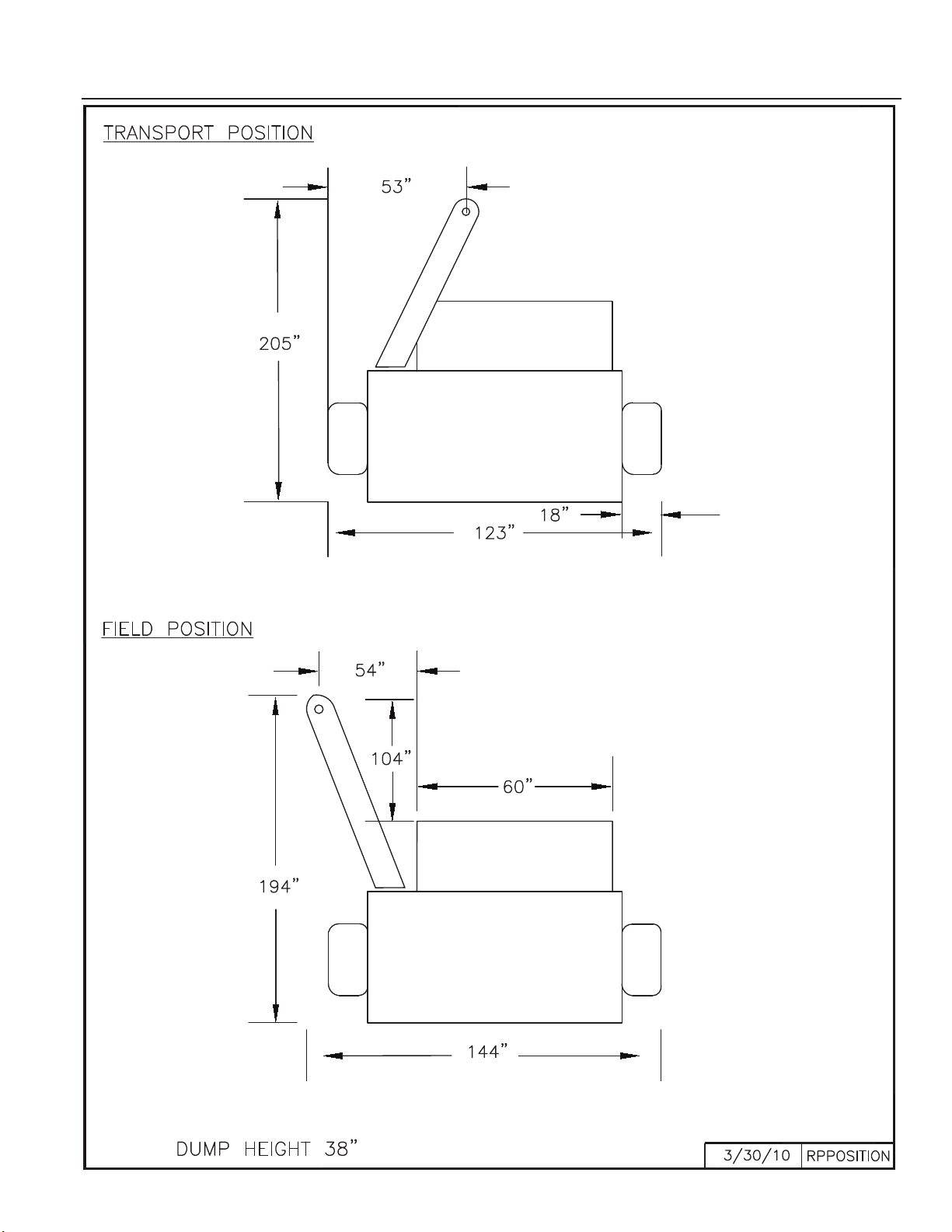
SECTION 3- PARTS
3-1
Page 14
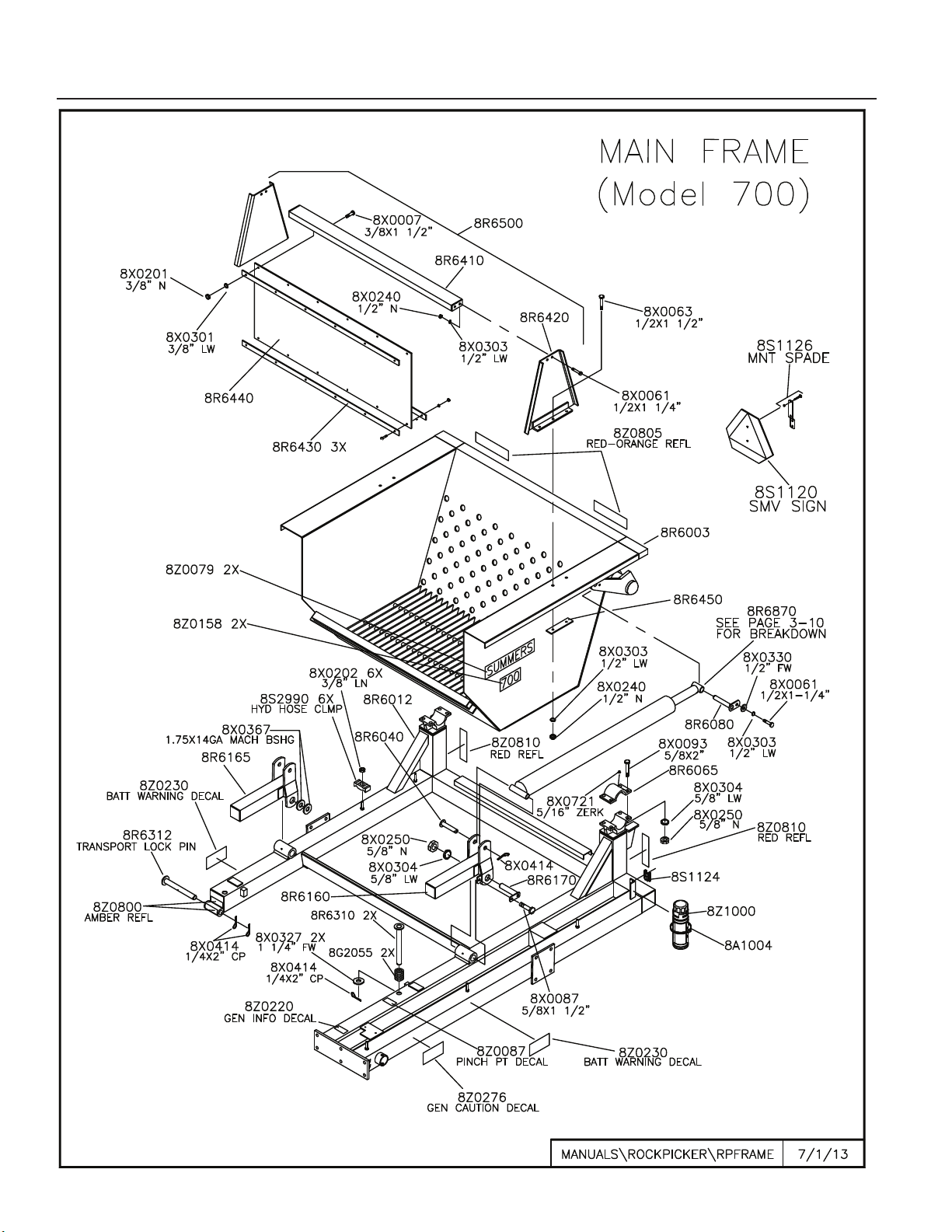
SECTION 3- PARTS
3-2
Page 15
SECTION 3- PARTS
3-3
Page 16
3-4
SECTION 3- PARTS
Page 17
3-5
SECTION 3- PARTS
Page 18
3-6
SECTION 3- PARTS
Page 19
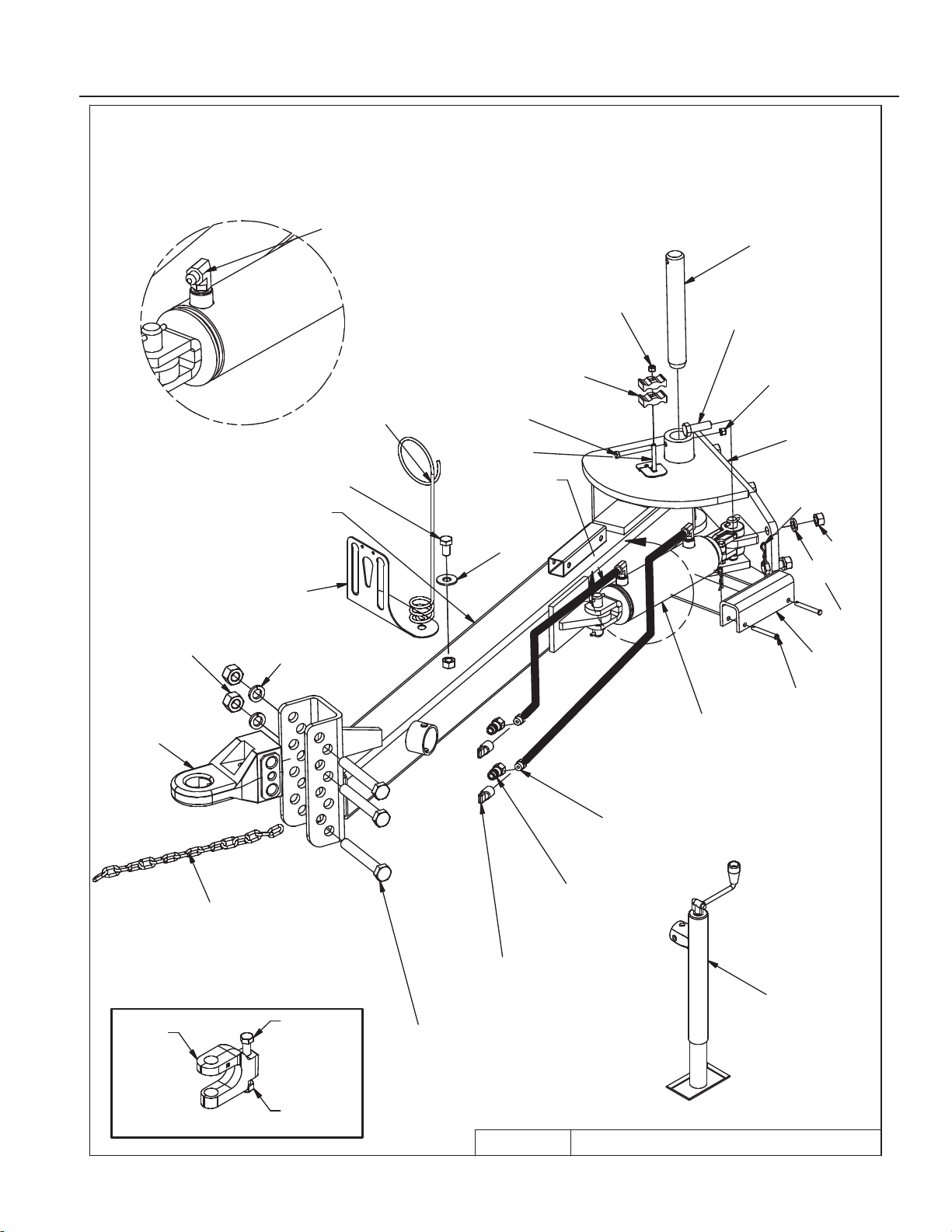
DETAIL A
HYD SWING HITCH
2/21/2013
8R7900.iam/
A
8D1660
8X0202
3/8" LN
8S2990
HOSE CLMP
8X0044
7/16" X 3-1/2"
8X0234
7/16" LNUT
8X0400
HPC
8X0462
CLVS PIN
8R7890
8J5510
3/4" ORB X #6 JIC(M)
8D3212
3/4" ORB TIP ISO
8S3095
HYD CAPLUG
8X0140
1 X 7"
8L0242
8X0280
1" N
8X0309
1" LW
8X0318
3/4" FW
8X0110
3/4 X 1.25"
8K8435
8N3136 (2X)
3/8 X 136"
HYDRAULIC SWING HITCH
(Model 700)
(8D8522)
8D0724
3/4X6" GR8
8X0262
3/4" LN
8J6010
3/4-16ORB X #6JIC(M) 90° ADP
8R7874
8R7880
3-1/2 X 8" CYL
(8K8610)
SEAL KIT (NOT SHOWN)
(8D8490)
(8D8500)
8D0720
(8X0112)
3/4X2-1/4"
(8X0306)
3/4" LW
8X1130
CRG 3/8"x3"
(8X0260)
3/4" N
SECTION 3- PARTS
3-7
Page 20
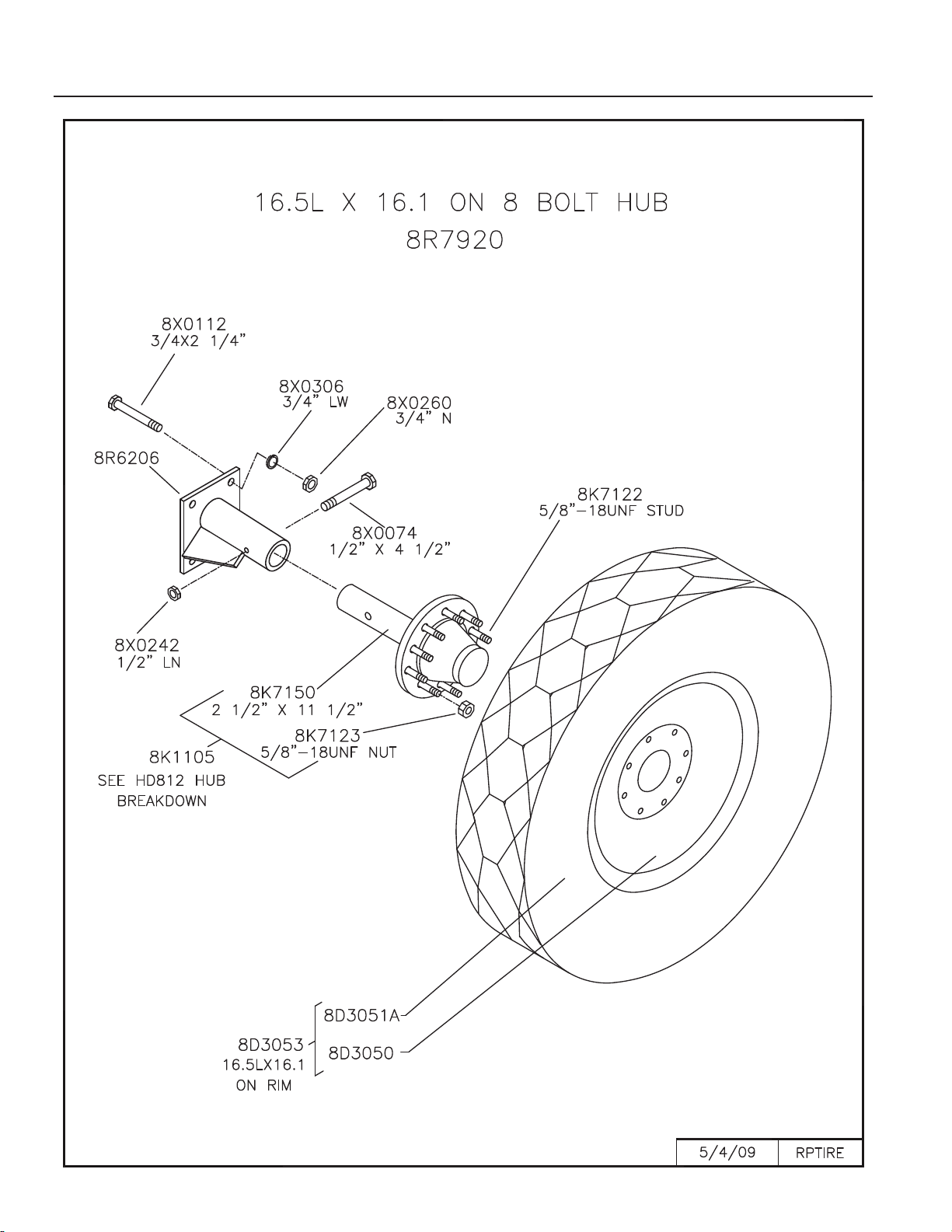
SECTION 3- PARTS
3-8
Page 21
8D5213
8D5213
8R6913
8K7341
N/A
N/A
8K7113
DC17
HVY
HUB 1. SEAL
2. INNE
BEARINRG
3. INN
RACERE
4. OURATER
CE
5. HUB ASSY
6. WSHEEL
TUD
7. WHEEL
NUT
8. WHEEL
BOLT
9. HUB
ZERK
10. OUT
BEARIERNG
11. A
WAS
XLE
HER
12. AX
NUT
LE 13. COTTER
PIN
G
14. HUB
CAP
ASKET
15. HUB
CAP
16. HUB
CAP
BOLT
H211
8G8220 8G8217 8G8230 8G8230 8G8211
A211
N/A N/A
8D5114 8X0708 8G8217 8D5119 8D5112 8X
16 3/
0410 8G8213 N/A
N/A
SE10 L44643 8L44610 L44610 HD WB10 1/4-28NF L44643 3/4" I.D. 3/4"- 16X1" DC11
H517
8D5234
8D5236
8D5238
8D5217 8D5332 8D5336 8D5210 8D5215 8D5214
2-20UNF
N/A
8X0708 8D5117 8S5219 8D5212 8X
14 3/16
0415
N/A
LM48548 LM48510 LM67010 H517 WB16 1/ 1/4-28NF LM67048 7/8" I.D. 7/8"- X1-1/2" DC13
H611
8D5221 8D5317 8D5334 8D5336
8D53
8D53
11 -09
16 10-
611
N/A N/A
8D5114
WB10 -09 8X0708 8D5117 8D5319 8D5312
4 3/16
8X0415
N/A
SE13 LM29749 LM29710 LM67010 H
8R6914
WB12 10- 1/4-28NF LM67048 1" I.D. 1"-1 X1-1/2" DC13
H614
8R6922** 8R6917 8R6925 8D5332 8R6911
614
N/A
8R6914 8X0708 8D5217 8D5319 8D5312
4 3/16
8X0415
N/A
SEE GBGI
INSTRUCTIONS
LM603049 LM603011 LM48510 H
N/A
WB12 1/4-28NF LM48548 1" I.D. 1"-1 X1-1/2" DC15
N/A
HD812
8K7127***
SEAL SE77
8K7117 8K7130 8K7132
8K71
8K7111
15-9/16"* 8K7116-9/16"*
WB40
N/A
8X0708 8K7118 8D5319 8X
3/16
8D5312
4
0415
N/A
8K7122-5/8" 8K7123-5/8"
N/A
8K7128***
SLEEVE SE
1
77
-
LM3780 LM3720 LM2720WHD812
B41
1/4-28NF LM2790 1" I.D. 1"-1 X1-1/2"
WB46 WB118
HD817
8K7344 7K7342 8K7346 8K7347 8K7340 8K7122-5/8" 8K7123-5/8"
WB118
8X0708 8K7343 8X0328 8D5314
-12 1
8X0414
N/A
SE42 LM387AS 382A LM501310 HD817 WB46
N/A
1/4-28NF LM501349 1.312 I.D. 1-1/4" /4X2" DC26
N/A
H1010
LT
8K7220 7K7217 8K7230 8K7232 8K7211 8K7215 8K7216
WB52
8X0708 8K7218 8X0328 8D5314 8X0414 8K7212 8K7213 8K7214
SE48 39585 39520 453A H1010-9 WB51
N/A
1/4-28NF 460 1.312 I.D. 1-1/4"-12 1/4X2" SE49 DC27 WB53
H1010
8K7221 8K7219 8K7231 8K7232 8K7210 8K7215 8K7216
WB52
8X0708 8K7218 8X0328 8D5314 8X0414 8K7212 8K7213 8K7214
SE67 33275 33462 453A H1010-11 WB51
N/A
1/4-28NF 460 1.312 I.D. 1-1/4"-12 1/4X2" SE49 DC27 WB53
H1020
8K7320 8K7317 8K7330 8K7332 8K7209 8K7215 8K7216
WB52
8X0708 8K7318 8X0366 N/A 8X0418 8K7312 8K7313 8K7214
SE55 HM218248 HM218210 HM212010 HDA1020 WB51
N/A
1/4-28NF HM212049 2.03" ID 2" - 160 5/16 X 2-1/2" SE59 DC28 WB53
*
Pre
2000
** GBGI (Not Shown), 8R6921 Triple Lip (Shown
)
CD2\MANUALS\10 2-26 HUB-AXLE COMPONENT
S
LAST REVISION: 3/2/201
0
*** Pre 2006 8K7120 (SE17
)
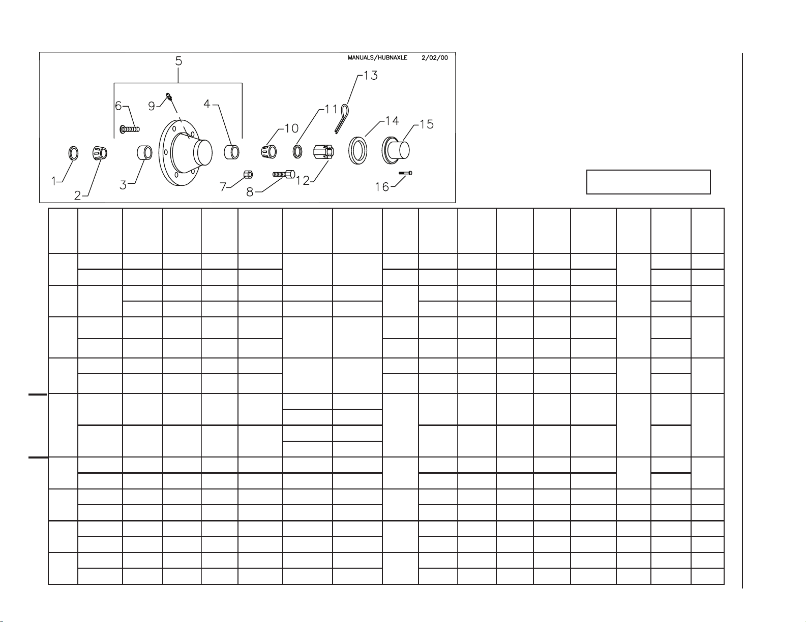
HUB AND AXLE COMPONENTS
Assembly Notes:
A. Before towing machine, pack wheel bearings and ll
1/2 of hub cavity with high quality bearing grease.
B. Tighten axle nut to 45 ft.-lbs, loosen nut until rst slot
is aligned with hole in axle, install cotter pin and bend to
retain.
Legend:
SMC Part Number
INDUSTRY Part Number or Size
3-9
ROCKPICKER
SECTION 3- PARTS
Page 22
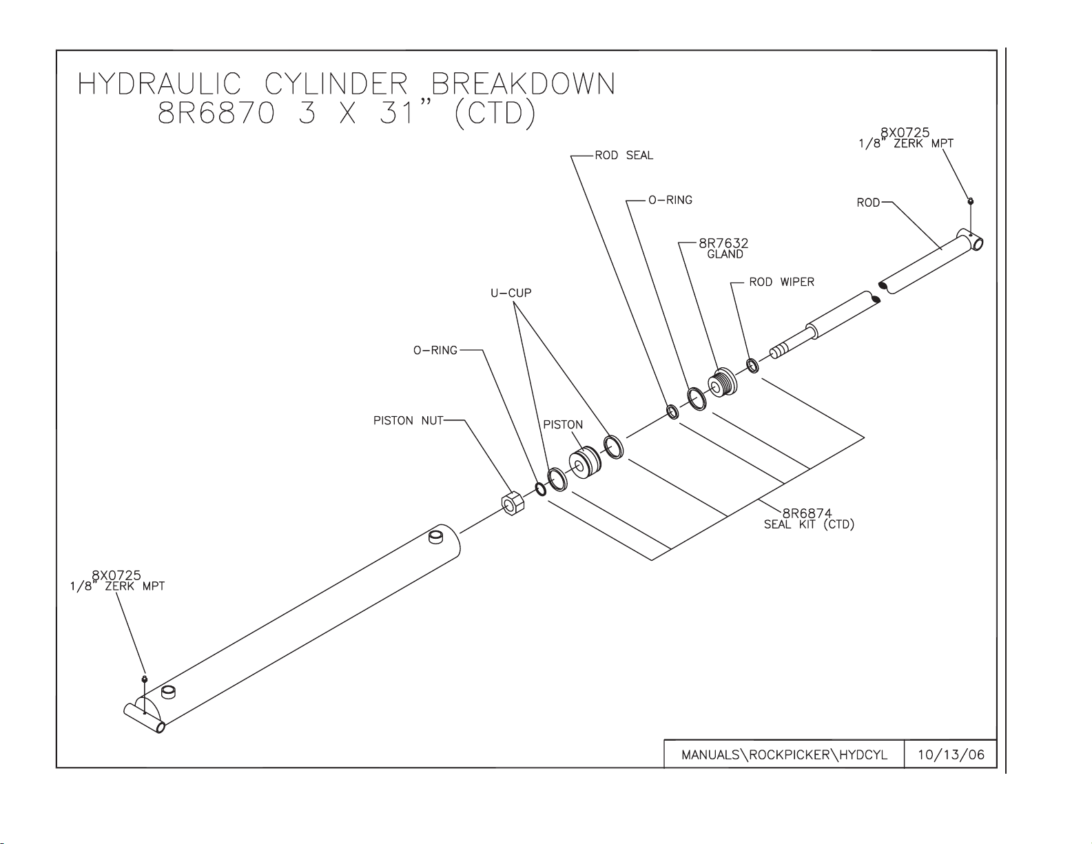
3-10
SECTION 3- PARTS
Page 23
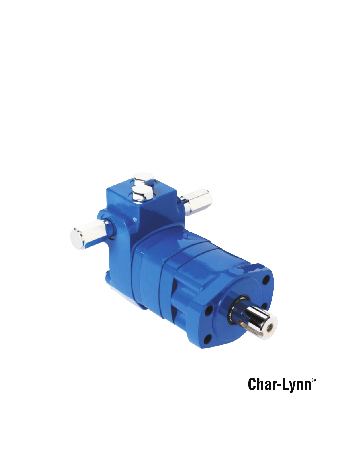
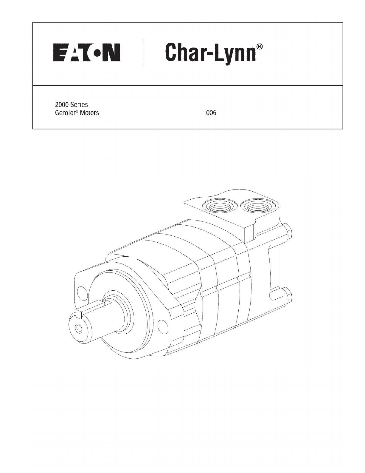
Disc Valve Motors
Integral Cross Over Relief Valve
Technical Manual
2000 Series
Page 24
Introduction
Features and Benefits
• Complete packaged sys-
tem solution, single source
for motor with relief valve
capability
• Relief valves as close to
the Geroler
®
as possible,
providing added protection.
• Eliminate leak points from
in-line or bolt-on relief’s
• Valves capable of full
motor flow and full motor
pressure.
• Provides added flexibility to
system design by allowing
motors to have individual
relief valve settings.
• Simplifies assembly, pur-
chasing, and system
design requirements
Eaton Char-Lynn®, your proven low speed high torque
motor supplier, now offers the Char-Lynn® 2000 Series
motor with our proven Eaton Vickers® Screw-in
Cartridge Valves integral to the motor. This compact
and efficient package offers increased value and cost
effectiveness to designing Eaton into your applications. Minimizing the use of hoses, tubing, and fittings
will reduce production and assembly time significantly.
Applications
• Skid Steer Attachments
• Swing Motor
• Brush Cutters & Mowers
• Harvesting Equipment
• Directional Boring
Any place pressure relief protection is optimal for system
or motor performance and life
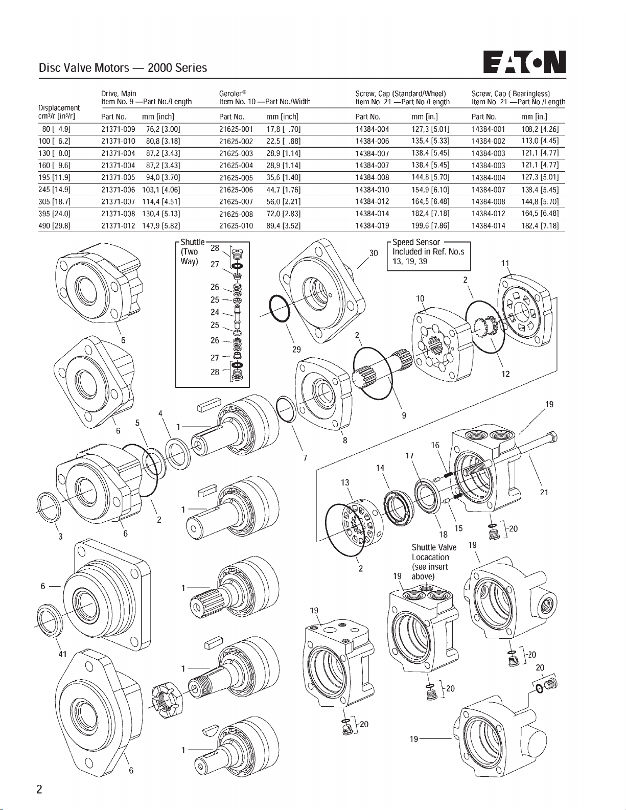
Replacement cartridges can be obtained by ordering the Item
Part Number as listed below.
ITEM PART # ITEM DESC. RELIEF VALVE SETTING
02-199291 RV5A-10-F-0-35/15 1500 PSI
02-199292 RV5A-10-F-0-35/17.5 1750 PSI
02-199293 RV5A-10-F-0-35/20 2000 PSI
02-199295 RV5A-10-F-0-35/22.5 2250 PSI
02-198563 RV5A-10-F-0-35/25 2500 PSI
02-199294 RV5A-10-F-0-35/27.5 2750 PSI
02-199296 RV5A-10-F-0-35/30 3000 PSI
2000 Series
Geroler® Element ............9 Displacements
Flow LPM [GPM]...............75 [20] Cont.**
115 [30] Inter.*
Speed ..................................Up to 924 RPM
Pressure Bar [PSI] ............200 [3000] Cont.
300 [4500] Inter.
Torque Nm [lb-in]..............845 [7470] Cont.
930 [8225] Inter.
** Continuous— (Cont.) Continuous
rating, motor may be run continuously
at these ratings.
* Intermittent— (Inter.) Intermittent
operation, 10% of every minute.
Page 25
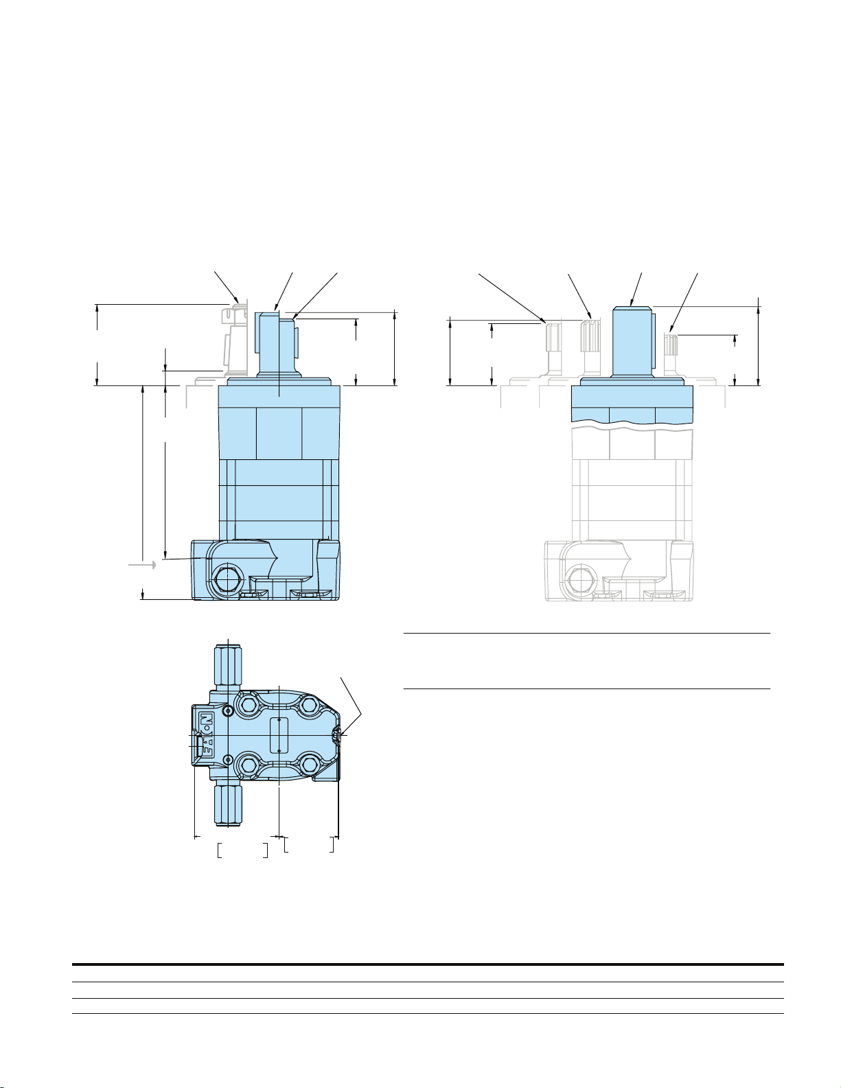
Standard Mount
Motors
65,3/62,7
[2.57/2.47]
Port B
1-1/4 inch Dia.
Tapered Shaft
*
10,2/7,8
[.40/.31]
*
X
Max.
Y
7/8-14 O-ring Staggered Ports,
G 1/2 (BSP) Staggered Ports
1-1/4 inch
Dia.Shaft
Case Drain
7/16-20 UNF-2B
SAE O-ring Port
1 inch and 25 mm
Dia.Shaft
56,7/54,3
[2.23/2.14]
52,4/49,7
[2.06/1.96]
*
SAE 6 B
Splined Shaft
*
56,7/54,3
[2.23/2.14]
Standard Rotation
Viewed from Shaft End
Port A Pressurized — CW
Port B Pressurized — CCW
*
52,4/49,7
[2.06/1.96]
*
1-1/4 inch Dia.
Splined Shaft
32 mm
Dia. Shaft
7/8 inch Dia.
Splined Shaft
65,8/63,5
[2.59/2.50]
42,2/39,8
[1.66/1.57]
*Subtract 4,1/3,6 [.16/.14] when order-
ing motor with 4-bolt magneto flange
*
*
2X
93.0/92.4
3.66/3.64
64.3/63.8
2.53/2.51
2000 Series Standard Motor
with 7/8-14 O-Ring Staggered
Ports or G1/2 (BSP)
Staggered Ports
DISPLACEMENT
cm3/r [in3/r] 80 [ 4.9] 100 [ 6.2] 130 [ 8.0] 160 [ 9.6] 195 [11.9] 245 [14.9] 305 [18.7] 395 [24.0] 490 [29.8]
Dim. X mm [in] 137,0 [ 5.40] 141,6 [ 5.58] 147,9 [ 5.83] 147,9 [ 5.83] 154,8 [ 6.10] 163,7 [ 6.45] 175,1 [ 6.90] 191,1 [ 7.53] 208,4 [ 8.21]
Dim. Y mm [in] 184,5 [ 7.26] 189,0 [ 7.44] 195,4 [ 7.69] 195,4 [ 7.69] 202,2 [ 7.96] 211,1[ 8.31] 222,6 [ 8.76] 238,6 [ 9.39] 255,8[10.07]
Page 26
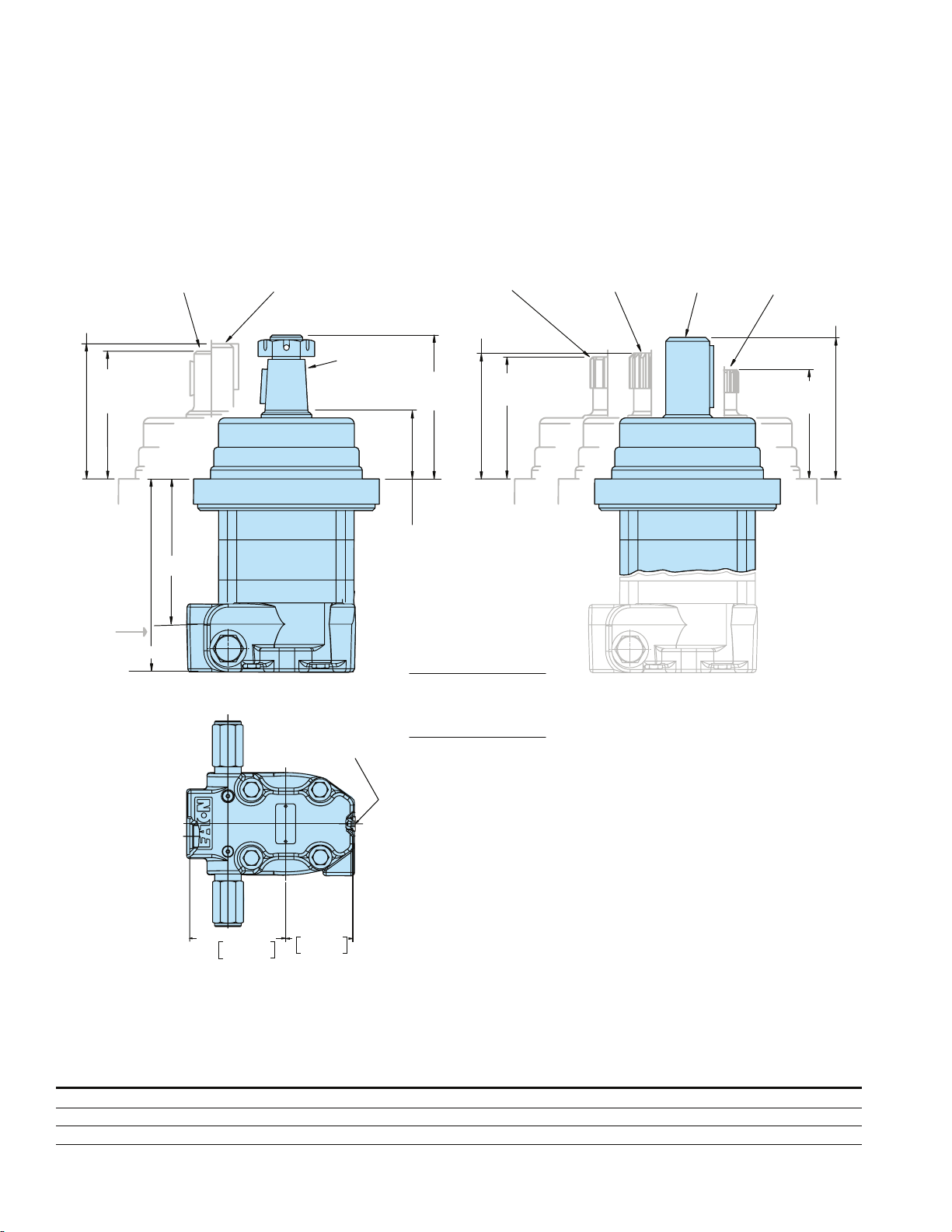
Wheel Mount
Motors
96,8/94,4
[3.81/3.72]
92,5/89,9
[3.64/3.54]
Port B
1 inch and 25 mm
Dia.Shaft
X
Max.
Y
7/8-14 O-ring Staggered Ports,
G 1/2 (BSP) Staggered Ports
1-1/4 inch
Dia.Shaft
Case Drain
7/16-20 UNF-2B
SAE O-ring Port
1-1/4 inch Dia.
Tapered Shaft
105,5/102,8
[4.15/4.05]
50,3/48,0
[1.98/1.89]
SAE 6 B
Splined Shaft
96,8/94,4
[3.81/3.72]
92,5/89,9
[3.64/3.54]
Standard Rotation
Viewed from Shaft End
Port A Pressurized — CW
Port B Pressurized — CCW
1-1/4 inch Dia.
Splined Shaft
32 mm
Dia. Shaft
7/8 inch Dia.
Splined Shaft
106,0/103,6
[4.17/4.08]
82,4/79,9
[3.24/3.14]
2X
93.0/92.4
3.66/3.64
64.3/63.8
2.53/2.51
2000 Series Wheel Motor
with 7/8-14 O-Ring Staggered
Ports or G1/2 (BSP)
Staggered Ports
DISPLACEMENT
cm3/r [in3/r] 80 [ 4.9] 100 [ 6.2] 130 [ 8.0] 160 [ 9.6] 195 [11.9] 245 [14.9] 305 [18.7] 395 [24.0] 490 [29.8]
Dim. X mm [in] 96,9 [ 3.82] 101,4 [ 4.00] 107,8 [ 4.25] 107,8 [ 4.25] 114,6 [ 4.52] 123,5 [ 4.87] 135,0 [ 5.32] 151,0 [ 5.95] 168,2 [ 6.63]
Dim. Y mm [in] 144,3 [ 5.68] 148,9 [ 5.86] 155,2[ 6.11] 155,2 [ 6.11] 162,1[ 6.38] 171,0 [ 6.73] 182,4 [ 7.18] 198,4 [ 7.81] 215,7[ 8.49]
Page 27
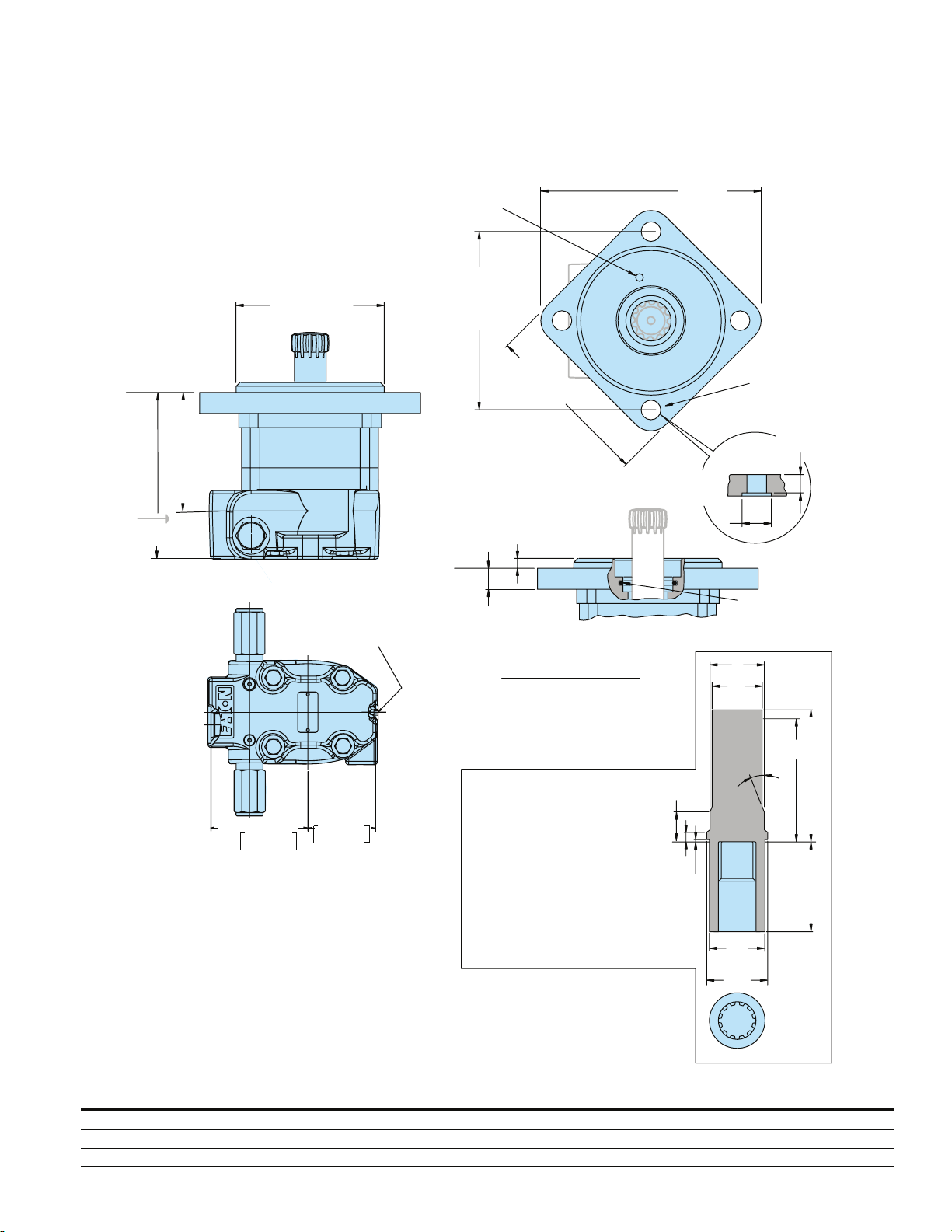
Bearingless
Motors
X
Port B
Max.
Y
7/8-14 O-ring Staggered Ports,
G 1/2 (BSP) Staggered Ports
101,60/101,47
[4.000/3.995]
Pilot Dia.
Case Drain
7/16-20 UNF-2B
SAE O-ring Port
Port for Internal
or External
Case Drain
127,0
[5.00]
Dia.
6.7/6,0
[.26/.24]
16,8/15,2
[.66/.60]
Standard Rotation
Viewed from Drive End
Port A Pressurized — CW
Port B Pressurized — CCW
119,2
[4.69]
Sq. Max.
157,5
[6.20]
Max. (2)
13,85/13,33
[.545/.525]
Dia. Thru (4)
14,22
[.560]
Min. (4)
24,06/23,54
[.947/.927]
O-ring Seal
Furnished
with Motor
C
D
E
N
F
G
J
2X
93.0/92.4
3.66/3.64
64.3/63.8
2.53/2.51
C 35,86 [1.412] Dia.
D 34,04 [1.340] Dia.
E 81,0 [3.19 ] Min. Full Form Dia.
F 86,1 [3.39 ] Max.
G 62,10 [2.445] Full Form Dia.
H 38,40 [1.512] Dia.
J 43,7 [1.72 ] Da.
K 25,91 [1.020]
L 8,25 [ .325]
M 0,89 [ .035]
N 15 °
Mating Coupling Blank
Eaton Part No. 13307-003
For 2000 Series Bearingless Motor
K
L
M
H
application information contact your
2000 Series Bearingless
Motor with 7/8-14 O-Ring
Staggered Ports or
G1/2 (BSP) Staggered Ports
DISPLACEMENT
cm3/r [in3/r] 80 [ 4.9] 100 [ 6.2] 130 [ 8.0] 160 [ 9.6] 195 [11.9] 245 [14.9] 305 [18.7] 395 [24.0] 490 [29.8]
Eaton representative (mating coupling
blanks available from Eaton Hydraulics).
Note: After machining blank, part must
be hardend per Eaton specification.
Dim. X mm [in] 79,0 [ 3.11] 83,5 [ 3.29] 89,9 [ 3.54] 89,9 [ 3.54] 96,8 [ 3.81] 105,6 [ 4.16] 117,1 [ 4.61] 133,1 [ 5.24] 150,3 [ 5.92]
Dim. Y mm [in] 126,8 [ 4.99] 131,4 [ 5.17] 137,7[ 5.42] 137,7 [ 5.42] 144,6[ 5.69] 153,5 [ 6.04] 164,9 [ 6.49] 180,9 [ 7.12] 198,2 [ 7.80]
Page 28

Model Code
Model Code for 2000
Series Motors
Sample Model Code:
The following 24-digit coding
system has been developed
to identify all of the configuration options for the 2000
Series motor
Model Code — 2000 Series Disc Valve Motors
1 2 3 4 5 6 7 8 9 10 11 12 13 14 15 16 17 18 19 20 21 22 23 24
M 0 2
Nos Feature Code Description
1 Product Series M Motor
2, 3 2000 Series 02 2000 Series
4, 5 Displacement cm
6, 7 Mounting Flange
3
/r [in3/r]
05 80 [ 4.9]
06 100 [ 6.2]
08 130 [ 8.0]
10 160 [ 9.6]
12 195 [11.9]
15 245 [14.9]
19 305 [18.7]
24 395 [24.0]
30 490 [29.8]
AD 4 Bolt (Bearingless)
101,6 [4.00] Pilot Dia. and
13,59 [.535] Dia. Mounting
Holes on 127,0 [5.00] Dia. B.C.
AC 2 Bolt SAE A (Std.)
82,5 [3.25] Pilot Dia and
13,59 [.535] Dia. Mtg. Holes
on 106,4 [4.19] Dia. B.C.
AB 4 Bolt (Wheel) 108,0 [4.25]
Pilot Dia. and 13,59 [.535]
Dia. Mounting Holes on
147,6 [5.81] Dia. B.C.
AH 4 Bolt (Standard) 82,5 [3.25]
Pilot Dia. and 14,59 [.535]
Dia. Mounting Holes on
106,4 [4.19] Dia. B.C.
AJ 4 Bolt Magneto (Std.)
82,5 [3.25] Pilot Dia. and
13,59 [.535] Dia. Mtg. Holes
on 106,4 [4.19] Dia. B.C.
AF 2 Bolt SAE B (Std.)
101,6 [4.00] Pilot Dia. and
14,35 [.565] Dia. Mtg. Holes
on 146,0 [5.75] Dia. B.C.
AP 4 Bolt (wheel compatible for
HAYES BRAKE) 107,9 [4.25]
Pilot Dia. and 13,59 [.535]
Dia. Mounting Holes on
147,6 [5.81] Dia. B.C. with
Turned Down Housing to
88,9 [3.50] Dia.
Use this model code to specify a motor with the desired
features. All 24-digits of the
code must be present when
ordering.
You may want to photocopy
the matrix below to ensure
that each number is entered
in the correct box.
00
Nos Feature Code Description
8, 9 Output Shaft 00 Bearingless
01 1 inch Dia. Straight with
Woodruff Key, 1/4-20
Threaded Hole and 38,4
[1.51] Max. Coupling Length
02 1–1/4 inch Dia. Straight with
Straight Key, 3/8-16 Threaded
Hole and 47,3 [1.86] Max.
Coupling Length
23 32 mm dia. Straight with
Straight Key, M8 x 1,25 -6H
Threaded Hole and 56,4
[2.22] Max. Coupling Length
04 1-1/4 inch Dia. Splined 14 T,
3/8-16 Threaded Hole and
33,0 [1.30] Min. Full Spline
Length and 45,5 [1.79] Max.
Coupling Length
03 1-1/4 inch Dia. Tapered with
Straight Key and Nut
05 1 inch SAE 6B Splined 6T,
1/4-20 Threaded Hole and
22,8 [.90] Min. Full Spline
Length and 28,8 [1.13] Max.
Coupling Length
07 7/8 inch Dia. Splined 13T,
15,2 [.60] Min. Full Spline
Length and 30,8 [1.21] Max.
Coupling Length
24 1–1/4 inch Dia. Straight with
Straight Key, 3/8-16 Threaded
Hole and Corrosion
Resistant (seal area to shaft
end)
25 1–1/4 inch Dia. Tapered with
Straight Key and Nut,
Corrosion Resistant (under
seal area only)
26 25 mm Dia. Straight with
Straight Key, M8 x 1,25 -6H
Threaded Hole and 38,4
[1.51] Max. Coupling Length
00
Page 29

Model Code
Sample Model Code:
Model Code — 2000 Series Disc Valve Motors
1 2 3 4 5 6 7 8 9 10 11 12 13 14 15 16 17 18 19 20 21 22 23 24
M 0 2
Nos Feature Code Description
10, 11 Port Type AA 7/8-14 UNF –2B SAE O-ring
12, 13 Case Flow
(Shuttles available with port code AA or AD only)
14 Low Pressure Relief
(LPR available with a combination of case flow code
04 or 05 and port code AA or AD only)
15, 16 Valve Option 00 None
17, 18 Accessories 00 None
(Staggered)
AG G 1/2 BSP Straight Thread
ports (Staggered)
AB Manifold Mount with 3/8-16
UNC Mounting Threads (3)
AE Manifold Mount with M10 x
1,5 -6H Mounting Threads (3)
AD 7/8-14 UNF –2B SAE O-ring
(End Ports)
AF 1–1/16 - 12 UN-2B O-ring
ports (Positioned 180∞
Apart)
01 7/16-20 UNF –2B SAE O-ring
(Case Drain)
02 G 1/4 (BSP) straight thread
port (Case Drain)
04 Shuttle Valve with 7/16-20
UNF –2B SAE O-ring (Case
Drain)
05 Shuttle Valve with G 1/4
(BSP) straight thread port
(Case Drain)
0 None
A Set @ 4,5 bar [65 psi]∞
B Set @ 15,2 bar [220 psi]∞
C Set @ 20,7 bar [300 psi]∞
AA Seal Guard
AB Speed Sensor (Std. With
Weatherpack shroud
connector)
AH Speed Sensor (Std. With
M12 connector)
AL Quadrature Speed Sensor
Version 2 with M12
00
Nos Feature Code Description
19, 20 Special Features (Hardware)
00 None
01 Viton Seals
10 Viton Shaft Seal
57 105 bar [1500 psi] Internal
Cross Over Relief Valve
(staggered 7/8” o-ring ports
only)
58 120 bar [1750 psi] Internal
Cross Over Relief Valve
(staggered 7/8” o-ring ports
only)
59 140 bar [2000 psi] Internal
Cross Over Relief Valve
(staggered 7/8” o-ring ports
only)
60 155 bar [2250 psi] Internal
Cross Over Relief Valve
(staggered 7/8” o-ring ports
only)
61 170 bar [2500 psi] Internal
Cross Over Relief Valve
(staggered 7/8” o-ring ports
only)
62 190 bar [2750 psi] Internal
Cross Over Relief Valve
(staggered 7/8” o-ring ports
only)
63 205 bar [3000 psi] Internal
Cross Over Relief Valve
(staggered 7/8” o-ring ports
only)
21 Special Features (Assembly)
0 None
A Flange Rotated 90∞
B Reverse Rotation
22 Paint/Special Packaging
0 No Paint
A Painted Low Gloss Black
B Corrosion Protected
23 Eaton Assigned Code when Applicable
0 Assigned Code
24 Eaton Assigned Design Code
0 Assigned Design Code
00
Page 30

Eaton
14615 Lone Oak Road
Eden Prairie, MN 55344
USA
Tel: 952 937-9800
Fax: 952 974-7722
www.hydraulics.eaton.com
Eaton
20 Rosamond Road
Footscray
Victoria 3011
Australia
Tel: (61) 3 9319 8222
Fax: (61) 3 9318 5714
Eaton
Eaton Fluid Power GmbH
Dr.-Reckeweg-Str. 1
D-76532 Baden-Baden, Germany
Tel: +49 (0) 7221 682-0
Fax: +49 (0) 7221 682-788
© 2003 Eaton Corporation
All Rights Reserved
Printed in USA
Document No. C-MOLO-TM001-E
September 2003
Page 31
Page 32
Page 33
Page 34
Page 35
Page 36
Page 37
Page 38
Page 39
Page 40
Page 41
Page 42

Eaton
Fluid Power Group
Hydraulics Business USA
14615 Lone Oak Road
Eden Prairie, MN 55344
USA
Tel: 952-937-9800
Fax: 952-294-7722
www.eaton.com/hydraulics
© 2008 Eaton Corporation
All Rights Reserved
Printed in USA
Document No. C-MOLO-TM008-E
Supersedes 07-124
December 2008
Eaton
Fluid Power Group
Hydraulics Business Europe
Route de la Longeraie 7
1110 Morges
Switzerland
Tel: +41 (0) 21 811 4600
Fax: +41 (0) 21 811 4601
Eaton
Fluid Power Group
Hydraulics Business Asia Pacific
11th Floor Hong Kong New World Tower
300 Huaihai Zhong Road
Shanghai 200021
China
Tel: 86-21-6387-9988
Fax: 86-21-6335-3912
Page 43
Page 44
Page 45
Page 46
Page 47
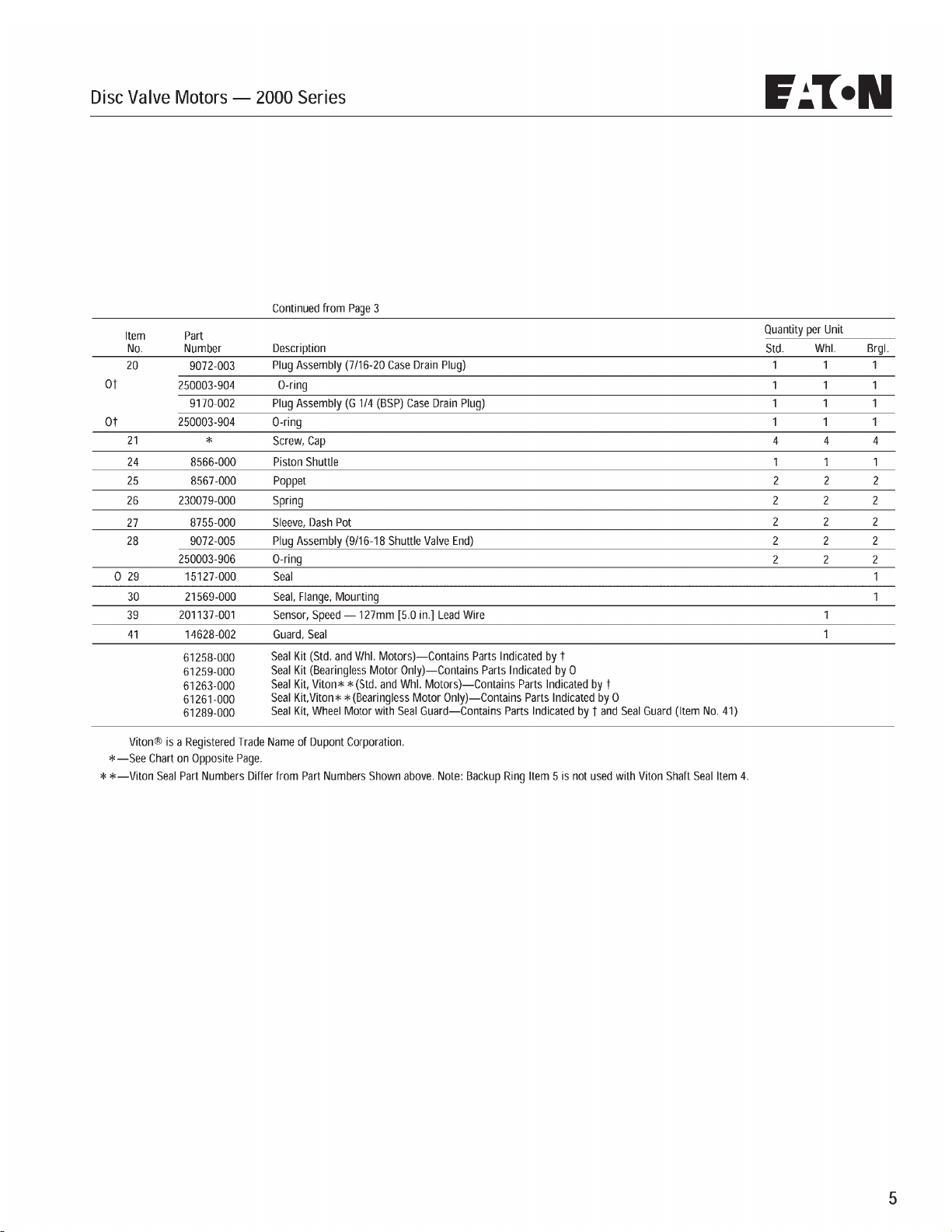
Page 48
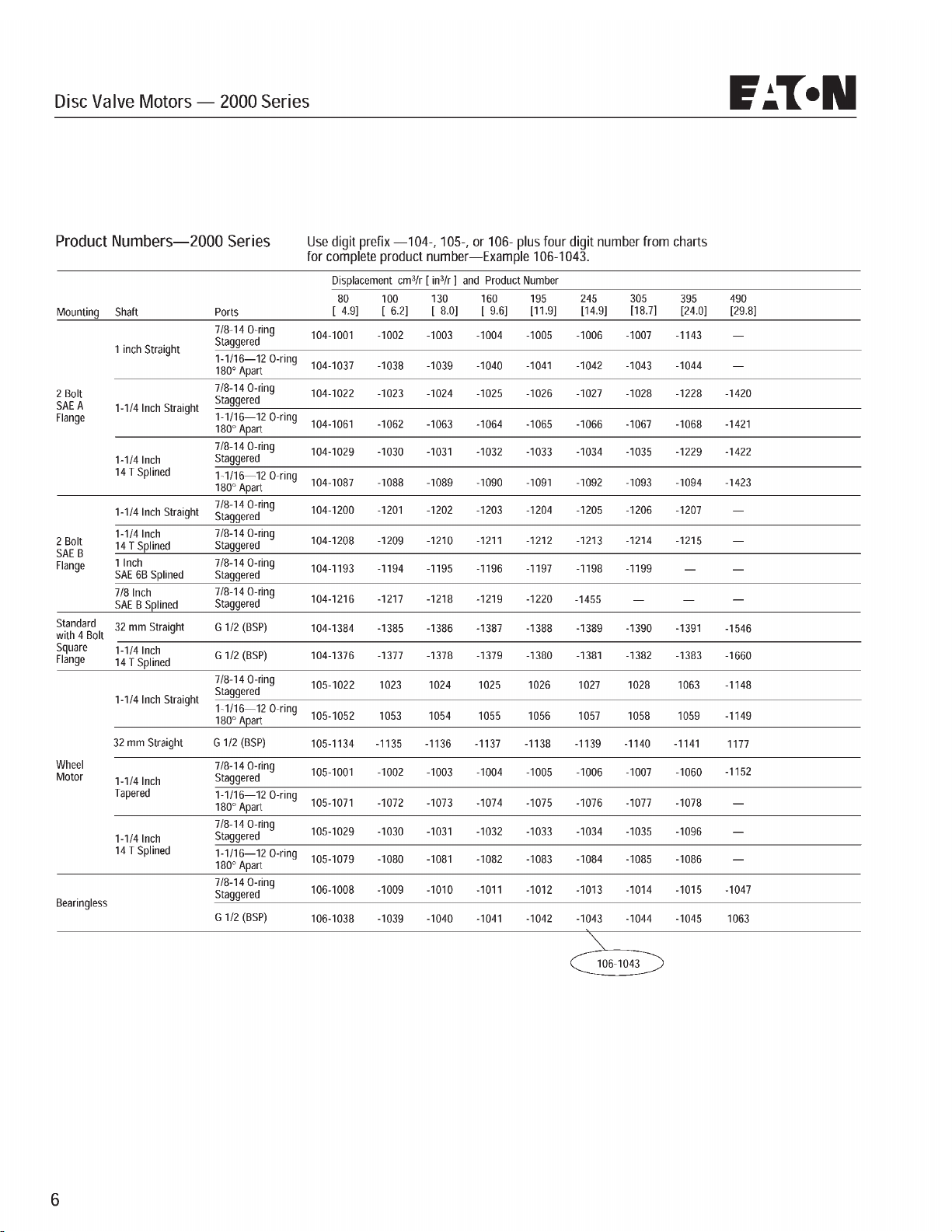
Page 49
Page 50
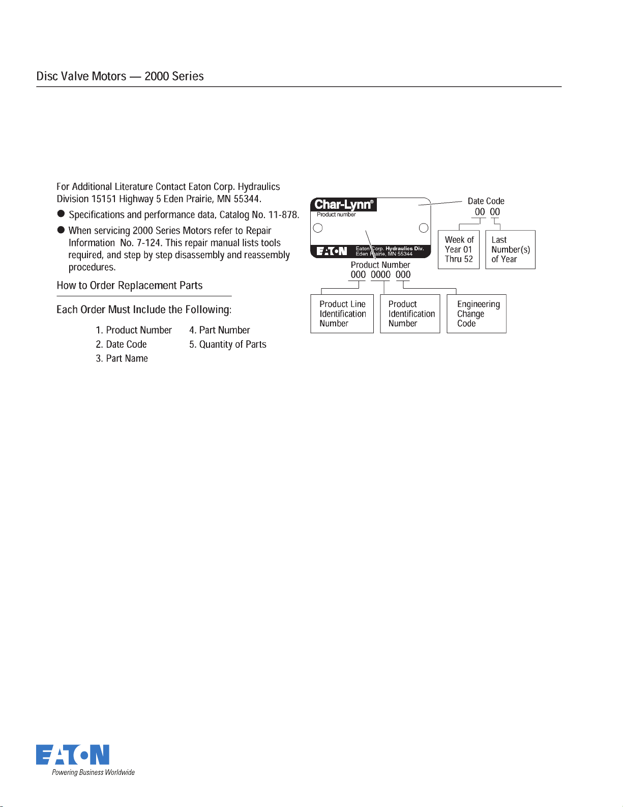
Eaton
Fluid Power Group
Hydraulics Business USA
14615 Lone Oak Road
Eden Prairie, MN 55344
USA
Tel: 952-937-9800
Fax: 952-294-7722
www.eaton.com/hydraulics
© 2008 Eaton Corporation
All Rights Reserved
Printed in USA
Document No. $.0-05.&
Supersedes
+BOVBSZ
Eaton
Fluid Power Group
Hydraulics Business Europe
Route de la Longeraie 7
1110 Morges
Switzerland
Tel: +41 (0) 21 811 4600
Fax: +41 (0) 21 811 4601
Eaton
Fluid Power Group
Hydraulics Business Asia Pacific
11th Floor Hong Kong New World Tower
300 Huaihai Zhong Road
Shanghai 200021
China
Tel: 86-21-6387-9988
Fax: 86-21-6335-3912
Page 51

History of Summers Manufacturing Co., Inc.
1965 – Summers Manufacturing is founded by Harley Summers, who purchases patent rights for Goebel truck and pickup hoists from the Goebel
Brothers of Lehr, ND. These hoists, produced in Harley Summers’ blacksmith shop the rst year, were distributed nationwide by a Cincinnati, Ohio, dealer. With increasing sales, the company soon outgrows the small shop. Summers wins the Herman harrow contract, beginning
the company’s Herman culti-harrow line. Summers builds a 7,200 square-foot factory in Maddock to meet the demand for truck and pickup
hoists, as well as Herman harrows.
1969 – Firm incorporates and becomes ofcially known as Summers Manufacturing Company, Inc.
1970 – Summers purchases rights to manufacture/market the Herman Harrow.
1973 – Company builds new 20,000 square-foot plant and ofces in Maddock, adding a 20,000 square-foot assembly plant in the fall of 1975 (com-
pleted in January 1976), bringing total square footage of Maddock factories to 47,000.
1977 – Summers introduces the Agri-sprayer, used in conjunction with the Herman culti-harrow to incorporate herbicides and liquid fertilizer.
1980 – Company purchases manufacturing and distributing rights to Crown rockpickers from Crown Manufacturers of Regina, Saskatchewan. This
forces another expansion project – a 26,000 square foot factory on a 24 acre site in Devils Lake, ND Industrial Park.
1981 – Company establishes a branch facility in Regina, Saskatchewan.
1982 – Devils Lake plant begins operations in January, manufacturing supersprayers and rockpickers. The Maddock factory begins producing the
Superweeder, a combination cultivator and harrow.
1983 – Summers buys manufacturing and distributing rights to the Fargo Field Sprayer line from Mid America Steel (formerly Fargo Foundry),
Fargo. This eld sprayer line is manufactured at the Devils Lake plant. Harley Summers is selected North Dakota’s small-businessman of
the year by the Small Business Administration.
1984 – Herman Diamond Disk, a disk harrow made in a diamond shape to reduce blade breakage from rocks, comes off the assembly line.
1985 – Summers signs a contract with Melroe Company of Bismarck to obtain exclusive manufacturing rights to the Melroe harrow line.
1989 – Summers purchases TorMaster Company of Hordean, Manitoba, giving the company a line of rolling packer equipment, comprised of harrow
packers and hydraulic fold coil packers.
1992 – A new engineering ofce/parts department is added to the Devils Lake factory.
1993 – Company adds two new products: a pickup-mounted sprayer with booms of 80 and 90 feet, and the Summers Superharrow, an extra-heavy-
duty residue-management tool designed for the minimum and no-till farmer.
1994 – a 50 by 125 foot addition to the Maddock factory is completed. Construction begins on a 24,576 square-foot addition to the Devils Lake fac-
tory, which enables the company to increase production of truck-mounted and pull-type supersprayers and rockpickers.
1996 – 1500 square foot ofce area added to the Maddock plant. Company introduces Chisel Plow with oating hitch and 700# trip assembly.
1997 – 16,800 square foot warehouse in Maddock purchased from local business.
1999 - Company introduces the Ultimate suspended boom trailer sprayer with hydraulic folding booms. Additional sizes added to the Chisel Plow
line, now ranging from 28’ to 54’.
2000 - Company introduces the Supercoulter, the innovative solution for excessive eld residue management on no-till, minimum-till, and conven-
tional-till farming operations.
2001 - Cold storage building completed at Devils Lake. Company extends boom lengths up to 110 feet on the Ultimate Supersprayer.
2002 - Company adds a warehouse and service man in Aberdeen, SD.
2003 - Company introduces the Ultimate NT Supersprayer featuring a bolt on axle for easier adjustment, and a new family of tanks that feature a
drainable sump and a common width dimension.
2004 - A 124 ft. x 310 ft. addition is added onto the current Devils Lake plant.
2005 - The Summers Superroller is added to the “Field Tested Tough” product line. Additional sizes of 56’, 58’ and 60’ are added to the Superchisel
line. Ultimate-Ultra NT Supersprayer introduced featuring 120’ & 133’ booms.
2006 - The Summers Coulter-Chisel, Rolling Choppers and 30’ Superroller were included in product line.
2007 - 62’ & 84’ 5 Section Landrollers and a 20’ Coulter-Chisel were introduced.
2008 - Disk-Chisels, ranging from 16’ to 40’ widths, are added to product line.
2009 – M105 and M108 Mounted Harrows added to selection of Mounted Attachments. SuperHarrow 2650, 50’ SuperCoulter, Hydraulic Fold Roll-
ing Chopper and 36” diameter Landrollers introduced.
2010 – Rolling Basket and 47’ Diamond Disk added to product line. A 124 ft. x 310 ft. addition to Devils Lake factory built for a state of the art
paint system.
2011 – Additional Supercoulter sizes were added along with larger tires for tillage implements. Ultimate and Ultra Supersprayers received an ad-
ditional tank size of 1650 gallons. Front Caster Wheel option was made available for chisel implements.
2012 – 41’, 46’ & 53’ Trail Type Landroller added to product line. Additional Superchisel sizes of 16’ & 20’ were added.
Summers distributes on a wholesale level to dealers and distributors throughout markets in North Dakota, South Dakota, Minnesota, Montana, Iowa,
Washington, Idaho, Oregon, Utah, Colorado, Kansas, Nebraska, Oklahoma, Texas, Manitoba, Saskatchewan, Alberta, British Columbia, Kazakhstan,
Russia and Australia, making it an international company.
Page 52
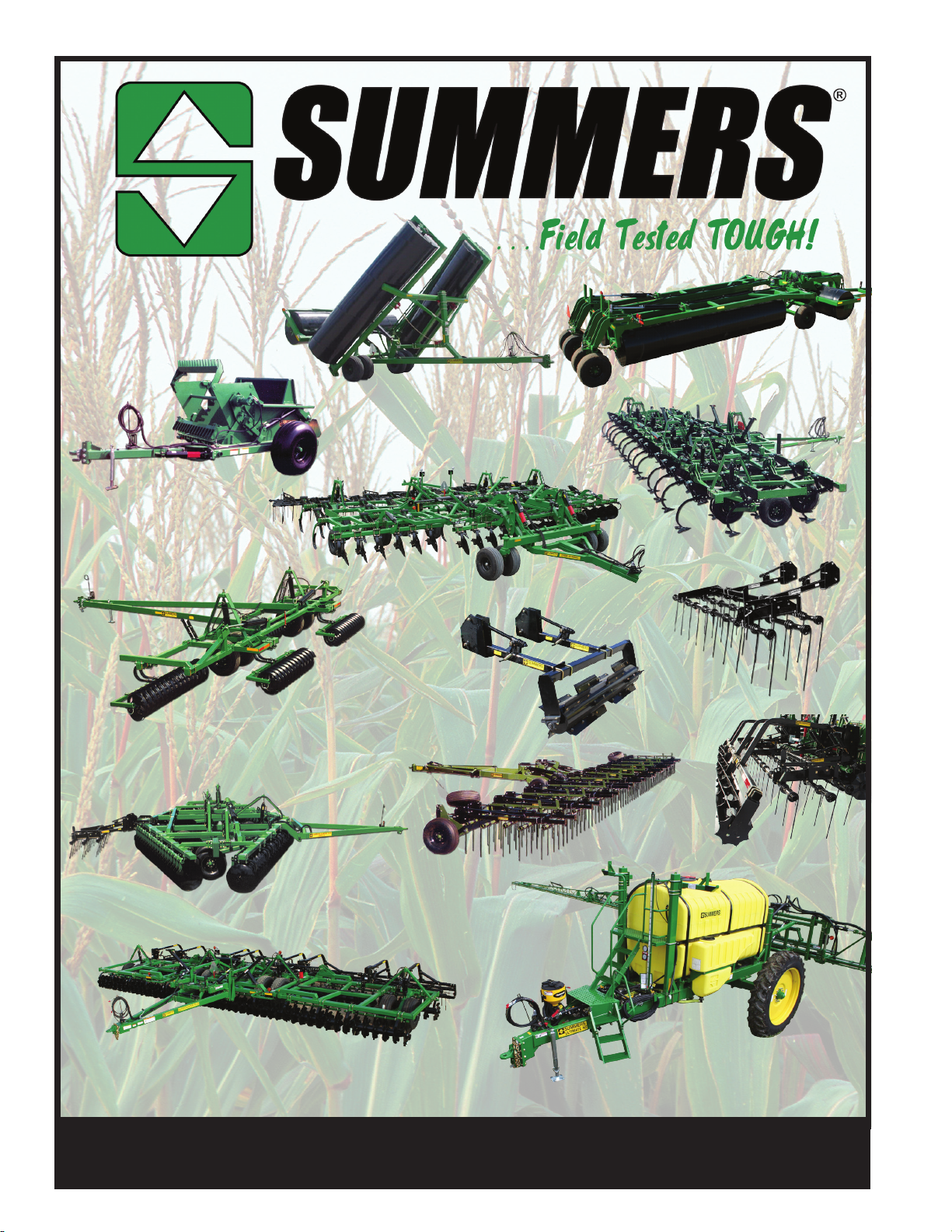
Model 700
Rock Picker
Hydraulic Fold
Coil Packer &
Hydraulic Fold
Rolling Chopper
Superrollers
Superchisel
Coulter-Chisel
Disk-Chisel
Mounted
Harrows
Rolling
Choppers
Superharrow Plus &
Superharrow 2650
Diamond Disk &
2510 DT
Supercoulter Plus
© Copyright 2013 Summers Manufacturing Co., Inc.
All Rights Reserved
To nd a dealer near you check out our website - www.summersmfg.com
or call us at: 1 (800) 732-4347
SUMMERS Manufacturing Company, Inc. Maddock & Devils Lake ND
Rolling
Baskets
Ultra & Ultimate NT
Supersprayer
11-1-12
 Loading...