

Page 1
Operator’s
30’ SUPERROLLER
SUPERROLLER
30’ SUPERROLLER
IMPORTANT
THE OPERATOR IS RESPONSIBLE
FOR ADJUSTING THE MACHINE SINCE
MACHINE DOES NOT COME “FIELD
READY” FROM FACTORY.
Manual
30’
CAUTION
READ & UNDERSTAND OPERATOR’S
MANUAL BEFORE USING MACHINE.
See www.summersmfg.com for latest version of all Summers Operator’s Manuals.
SUMMERS MANUFACTURING CO., INC.
WEB SITE: www.summersmfg.com
MADDOCK, NORTH DAKOTA 58348 ................................... (701) 438-2855
DEVILS LAKE, NORTH DAKOTA 58301 ............................... (701) 662-5391
8Z1076 © Summers Mfg. Co., Inc. 2013 Printed in USA
Page 2

Warranty
Summers warrants only products of its manufacture against operational failure caused by defective materials
or workmanship which occur during normal use within 12 months from the date of purchase by the end user from
Summers’ dealer.
Summers’ obligation is to replace free of charge any part of any product that Summers inspection shows to be
defective excluding transportation charges to Maddock, ND or Devils Lake, ND and return and also excluding all
transportation costs from Summers’ dealer to the dealer’s customer and all other costs such as removal and installation expense.
Summers shall not be liable for loss of time, manufacturing costs, labor, material, loss of prots, consequential
damages, direct or indirect, because of defective products whether due to rights arising under the contract of sale or
independently thereof, and whether or not such claim is based on contract, tort or warranty.
Written permission for any warranty claim return must be rst obtained from authorized Summers’ personnel.
All returns must be accompanied with a complete written explanation of claimed defects and the circumstances of
operational failure.
Written warranty for all component parts used in the manufacture of Summers products is available upon request.
Warranty of such component parts will be determined by said component manufacturer upon their inspection of the
claimed defective part.
This express warranty is the sole warranty of Summers. There are no warranties, which extend beyond the warranty herein expressly set forth. The sales for products of Summers under any other warranty or guarantee express
or implied is not authorized. This warranty voids all previous issues.
SUMMERS MANUFACTURING CO. INC.
MADDOCK, NORTH DAKOTA 58348
DEVILS LAKE, NORTH DAKOTA 58301
2/95
IH 3/2013
Page 3

INTRODUCTION
This manual provides the following information about your Summers Land Roller.
SECTION CONTENTS
Section 1 – SAFETY explains important safety precautions and familiarizes the Operator with the
decals and their locations.
Section 2 – ASSEMBLY includes step by step assembly instructions for your Summers Land Roller.
Section 3 – LAND ROLLER OPERATION provides necessary information for the operation and ad-
justment of the machine.
Section 4 – MAINTENANCE covers recommended mechanical maintenance. TROUBLESHOOTING
provides a quick reference to solving problems. SPECIFICATIONS lists important dimensions, capacities and other technical information.
Section 5 – PARTS
OTHER ITEMS OF IMPORTANCE
A. Summers Mfg. Co., Inc. strongly recommends that each Land Roller Operator READ and UNDERSTAND the Operator’s Manual before using the machine. In addition, this Operator’s Manual should
be REVIEWED at least ANNUALLY thereafter.
B. It is the policy of this company in improve its products whenever possible and practical to do so.
We reserve the right to make changes or improvements in the design or construction of parts at any
time without incurring obligations to install such changes on products previously delivered.
C. Reference to “right” and “left” in this manual is determined when machine is viewed from the rear.
D. Parts are referenced in each drawing with the Summers Manufacturing Part Number. Use this Part
Number when ordering replacement parts from your Summers dealer. See back section of manual for
description of each Part Number.
E. WARNING – DO NOT ATTEMPT to raise machine into transport position if mud has built up on
rollers or if machine weight has been increased by any other means. Mechanical failure may occur.
F. Ability to safely operate the Summers Superroller is determined by both tractor horsepower and
weight. The minimum tractor weight for operating this implement is 16,000 lb. Minimum tractor
engine horsepower is 125. Dual tires or single tires set at maximum width are required for safe operation of Land Roller.
G. Never tow this implement with less than an 16,000 lb. vehicle. Tongue weight in transport and
eld positions 1150 lbs.
H. NEVER ALLOW anyone to work under Land Roller.
OWNER REGISTER
Name ____________________________________ Size _________________________________________
Address _________________________________ Serial Number _______________________________
City _____________________________________
State/Prov. ______________________________ Date Purchased ______________________________
Mail Code ________________________________ Dealer _______________________________________
(located by the hitch piece)
i
Page 4

TABLE OF CONTENTS
SECTION 1 – SAFETY
Safety-Alert Symbol .....................................................................................................................................1-1
General Safety Practices ...............................................................................................................................1-1
Safety During Transport ................................................................................................................................1-2
Safety Decals ................................................................................................................................................1-2
Decals and Their Locations....................................................................................................................1-2-1-6
SECTION 2 – ASSEMBLY
General Assembly Safety Instructions .......................................................................................................... 2-1
Safety Alert Symbol ...................................................................................................................................... 2-1
General Safety Practices ...............................................................................................................................2-2
Set-Up of Frame ................................................................................................................................ 2-3 – 2-13
Hydraulic Set-Up ............................................................................................................................. 2-14 - 2-15
Wiring & Safety Installation .......................................................................................................................2-16
SECTION 3 – LAND ROLLER OPERATION
Land Roller Operation Safety .......................................................................................................................3-1
Steps Prior to Operation ................................................................................................................................3-1
Initial Hookup ...............................................................................................................................................3-2
Steps Required to Unfold from Transport to Field Position .........................................................................3-3
Field Operation .............................................................................................................................................3-4
Steps Required to Fold from Field to Transport Position .............................................................................3-4
Transporting ..................................................................................................................................................3-5
Unhooking Land Roller From Tractor ..........................................................................................................3-6
SECTION 4 – MAINTENANCE
Maintenance Safety .......................................................................................................................................4-1
Maintenance for after the First Day Four Hours of Operation .....................................................................4-1
Daily and Periodic Maintenance ...................................................................................................................4-1
Storage, Troubleshooting, Specications ......................................................................................................4-2
SECTION 5 – PARTS
Hitch & Center ..............................................................................................................................................5-2
Hydraulics .....................................................................................................................................................5-3
Roller .............................................................................................................................................................5-4
Safety Lights .................................................................................................................................................5-5
Hub and Axle Components ...........................................................................................................................5-6
Acre Meter Option ........................................................................................................................................5-7
Part Numbers .................................................................................................................................... 5-8 – 5-10
ii
Page 5
SECTION 1 - SAFETY
SAFETY-ALERT SYMBOL
This symbol is used to denote possible danger and
care should be taken to prevent bodily injury.
This symbol means:
ATTENTION! BECOME ALERT!
YOUR SAFETY IS INVOLVED!
Denition of each Signal Word used in conjunction with the Safety-Alert symbol.
indicates an imminently hazardous situation which, if not avoided, will result in death
DANGER
or serious injury. This signal word is to limited to the most extreme situations.
indicates a potentially hazardous situation which, if not avoided, could result in death
WARNING
CAUTION
1. READ AND UNDERSTAND Operator’s Manual before using machine. Review at least annually thereafter.
2. VERIFY all safety devices and shields are in place before using machine.
3. KEEP hands, feet, hair and clothing away from moving parts.
4. STOP engine, place all controls in neutral, set parking brake, remove ignition key and wait for all moving parts to stop before servicing, adjusting, maintaining or unplugging.
5. BE CAREFUL when working around high pressure hydraulic system.
6. ALWAY S make sure Land Roller is lowered into eld position (cylinders extended), it is blocked to prevent
movement and that pressure is relieved from hydraulic circuits before servicing.
7. DO NOT ALLOW RIDERS.
or serious injury.
indicates a potentially hazardous situation which, if not avoided, may result in minor
or moderate injury. It may also be used to alert against unsafe practices.
GENERAL SAFETY PRACTICES
8. USE EXTREME CARE when making adjustments.
9. KEEP CHILDREN AWAY from machinery at all times.
10. NEVER ALLOW anyone to work under Land Roller.
11. WARNING – DO NOT ATTEMPT to raise machine into transport position if mud has built up on rollers or if
machine weight has been increased by any other means. Mechanical failure may occur.
1-1
Page 6

SAFETY DURING TRANSPORT
1. Ability to safely operate the Summers Superroller is determined by both tractor horsepower
and weight. The minimum tractor weight for operating this implement is 16,000 lbs. Minimum tractor engine horsepower is 125. Dual tires or single tires set at maximum width are
required for safe operation of Land Roller.
2. ONLY TOW at a safe speed – 20 MPH MAXIMUM. Use caution when making corners or
meeting trafc.
3. USE Safety Lights and Safety Chain between tractor drawbar and implement hitch when
transporting on public roads.
4. ALWAYS install hitch safety chains and close wing lock hydraulic valve before transporting
on public roads.
5. FOLLOW ALL local laws governing transporting of farm machinery.
6. Use additional caution and reduce speed when towing under adverse conditions, when
turning and when on unlevel surfaces. Frequently check for trafc from rear, especially
during turns.
SECTION 1 - SAFETY
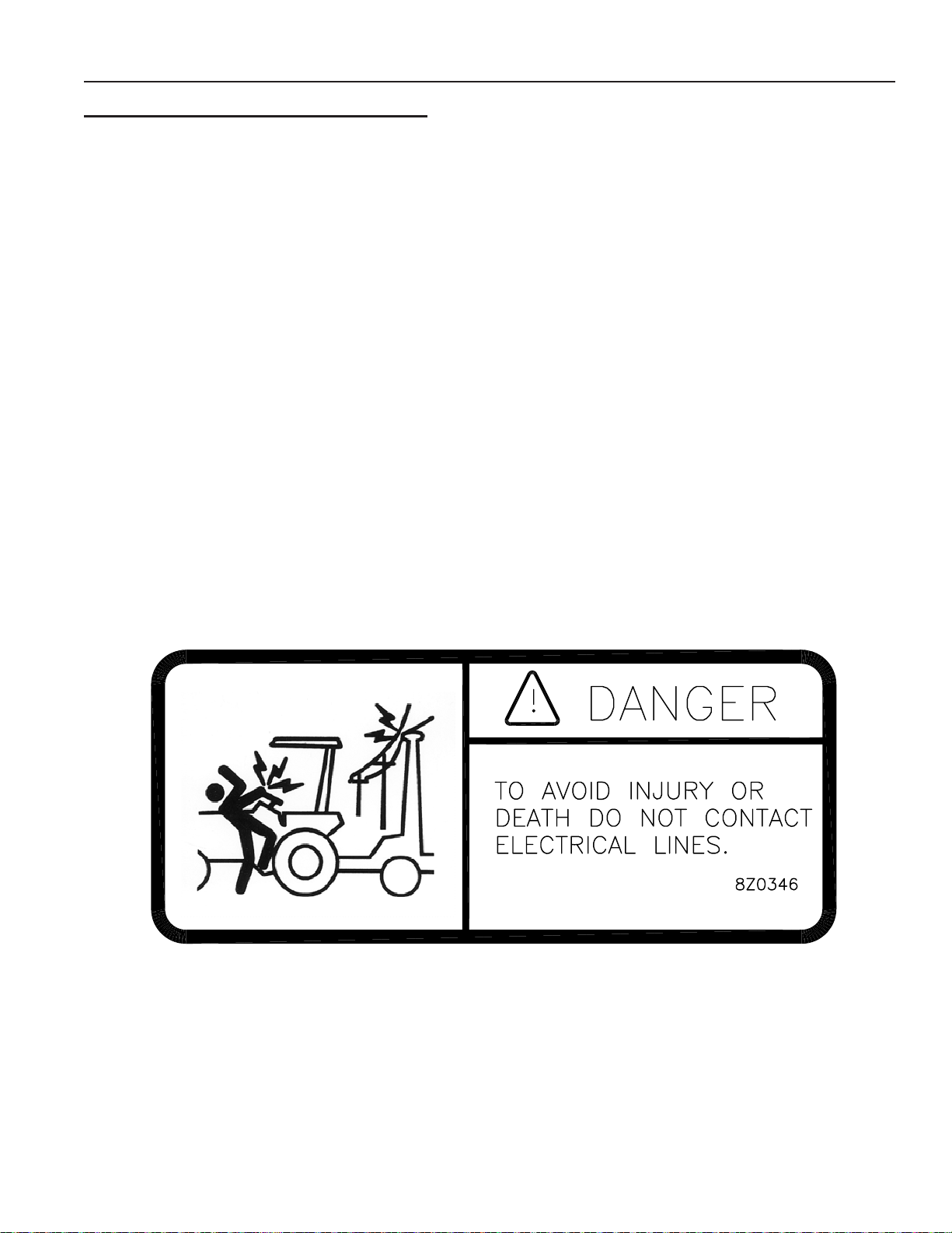
7. Stay clear of overhead lines and other overhead obstructions.
SAFETY DECALS
1. KEEP SAFETY DECALS CLEAN.
2. REPLACE missing or unreadable decals. New decals are available from your Summers
dealer by ordering correct part number (PN) located on the decal.
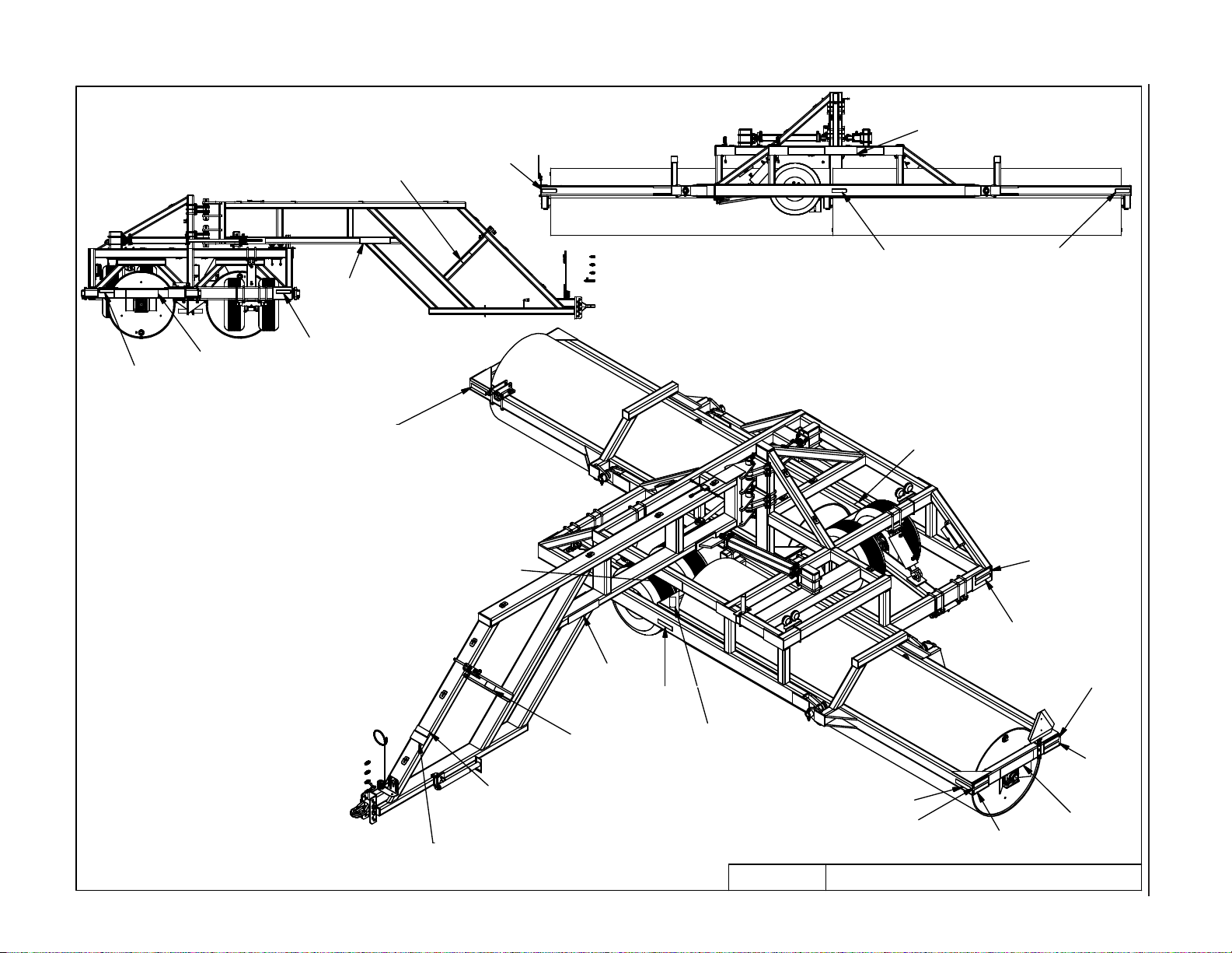
DECALS AND THEIR LOCATIONS
1. PN 8Z0075 – DECAL FOR REMOVING TRANSPORT LOCKS
2. PN 8Z0079 – DECAL FOR COMPANY IDENTIFICATION
1-2
Page 7
SECTION 1 - SAFETY
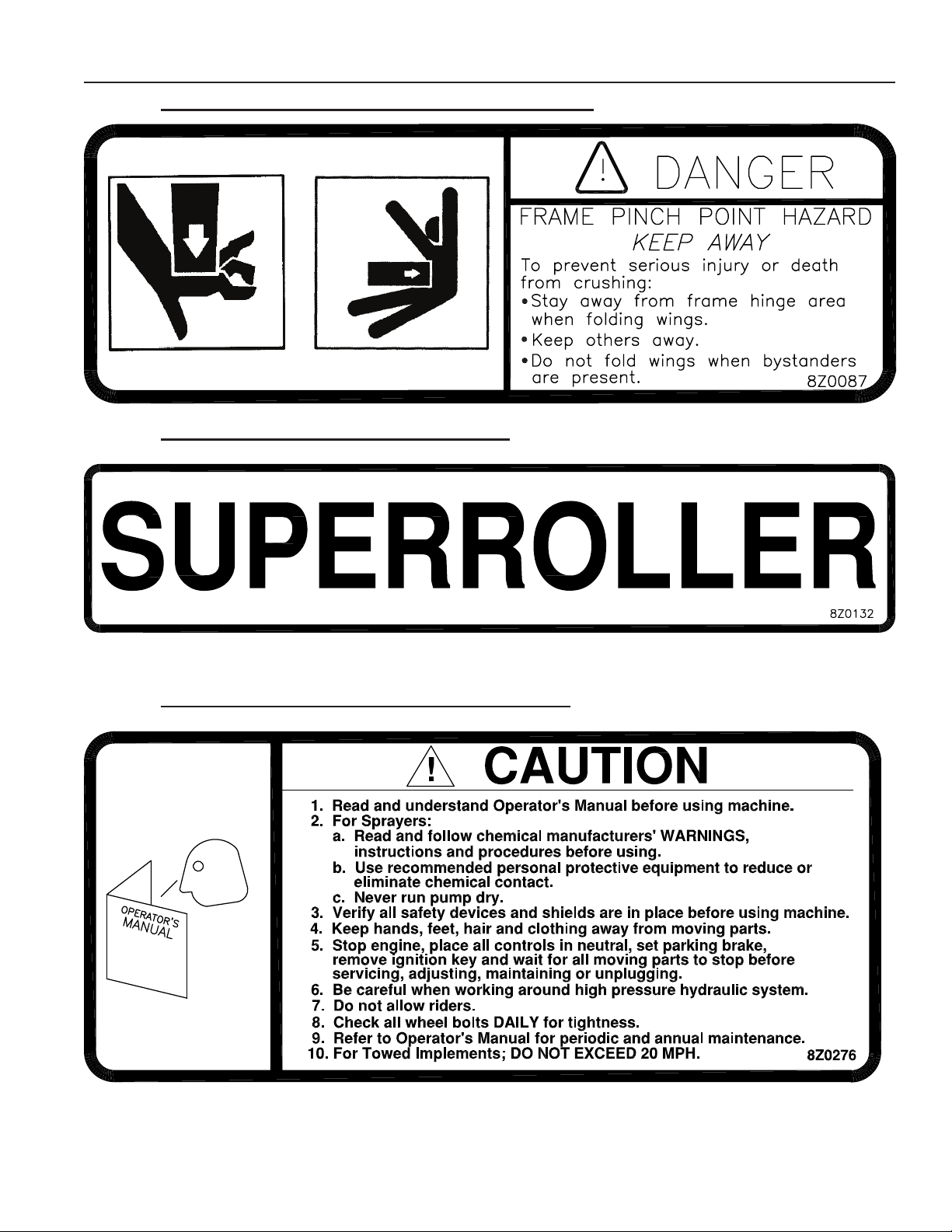
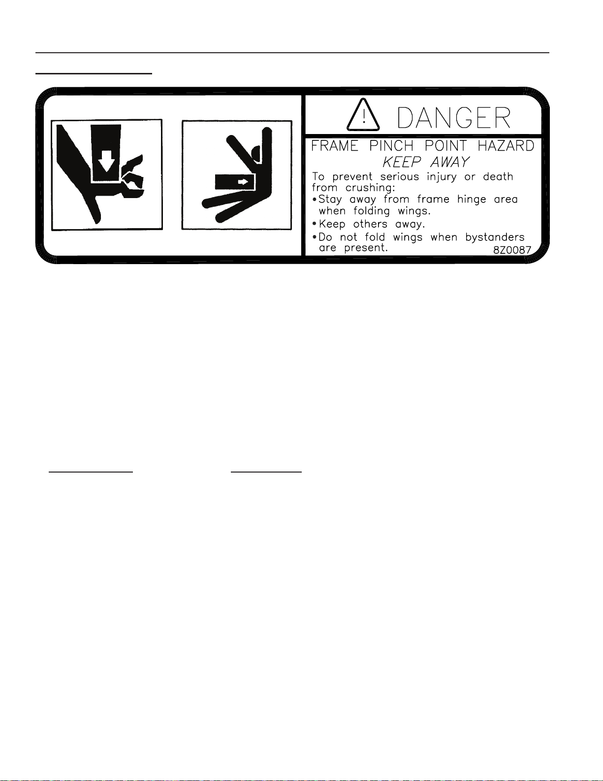
3. PN 8Z0087 – DECAL FOR PINCH POINT HAZARD
4. PN 8Z0132 – SUPERROLLER ID DECAL
5. PN 8Z0276 – DECAL FOR GENERAL CAUTION
1-3
Page 8

SECTION 1 - SAFETY
6. PN 8Z0800 – AMBER REFLECTOR
7. PN 8Z0805 – RED-ORANGE REFLECTOR
8. PN 8Z0810 – RED REFLECTOR
SAFETY LIGHT OPERATION
The Summers Safety Light Kit is equipped with a 7 pin connector which meets SAE J560 specication. To protect 7
pin connector, store in dust cap (8K8067) when not attached to towing vehicle.
On most towing vehicles WITHOUT brake lights:
Amber lights will turn on with ashers or turn signals.
Red lights will turn on with parking, road or eld lights.
On most towing vehicles WITH brake lights:
Amber lights will turn on with ashers, turn signals OR when brake is applied.
Red lights will turn on with parking or road lights.
1-4
Page 9
8Z0087
8Z0079
8Z0800
1-5
8Z0805
8Z0079
8Z0132
8Z0805
8Z0805
8Z0079
8Z0132
8Z0800
8Z0800
8Z0087
8Z0800
SECTION 1 - SAFETY
8Z0800
8Z0810
8Z0805
8Z0276
8Z0087
8Z0087
8Z0087
8Z0800
8Z0805
9LR3042.iam/
8Z0810
8Z0079
8Z0810
DECALS8/7/2012
Page 10

SECTION 1 - SAFETY
1-6
Page 11

SECTION 2 - ASSEMBLY
GENERAL ASSEMBLY SAFETY PRACTICES
1. READ AND UNDERSTAND Operator’s Manual before assembly of machine.
2. If machine is to be assembled INDOORS, check that exit door is a MINIMUM OF 11’
WIDE and a MINIMUM of tractor height.
3. Reference to “RIGHT” and “LEFT” is determined when machine IS VIEWED FROM
THE REAR.
4. Reference to “FORWARD” means TOWARDS THE TRACTOR.
5. Reference to “REAR” means AWAY FROM THE TRACTOR.
SAFETY-ALERT SYMBOL
This symbol is an alert to the potential
for personal injury. This symbol means
ATTENTION! BECOME ALERT!
YOUR PERSONAL SAFETY IS INVOLVED!
2-1
Page 12

SECTION 2 - ASSEMBLY
GENERAL SAFETY PRACTICES
YOU ARE RESPONSIBLE
for the safe assembly of the
machine.
DO NOT ALLOW CHILDREN
or other unauthorized persons
within the assembly area.
WEAR PERSONAL
PROTECTIVE EQUIPMENT
which includes a hard hat,
eye protection, work gloves
and steel toed boots with slip
resistant soles.
BLOCK UP ANY RAISED PART
of the machine. Be sure machine
is stable after blocking.
ALWAYS INSPECT LIFTING
CHAINS AND SLINGS for
damage or wear.
BE SURE LIFTING DEVICE
IS RATED TO HANDLE THE
WEIGHT.*
STOP ENGINE, place all
controls in neutral, set parking
brake, remove ignition key and
wait for all moving parts to stop
before servicing or adjusting.
DO NOT MODIFY the equipment
or substitute parts in any way.
Unauthorized modication may
impair the function and/or safety
of the machine.
USE SUITABLE LIFTING
DEVICE for components which
could cause personal injury.
*APPROXIMATE WEIGHTS OF COMPONENTS
PN DESCRIPTION WEIGHT (LB)
8P6000 HITCH 1780
8P6030 CENTER SECTION 3950
8P6115 WING LEFT AND RIGHT 1166
ALWAYS make sure Land Roller
is lowered into eld position, it
is blocked to prevent movement
and that pressure is relieved
from hydraulic circuits before
servicing.
USE EXTREME CARE when
assembling, servicing or
adjusting.
PN DESCRIPTION WEIGHT (LB)
8P4215 ROLLER, 15’ 4285
8P8630 BOX HARDWARE PARTS 1250
2-2
Page 13
SECTION 2 - ASSEMBLY
1
2
Wing to Main Frame Installation
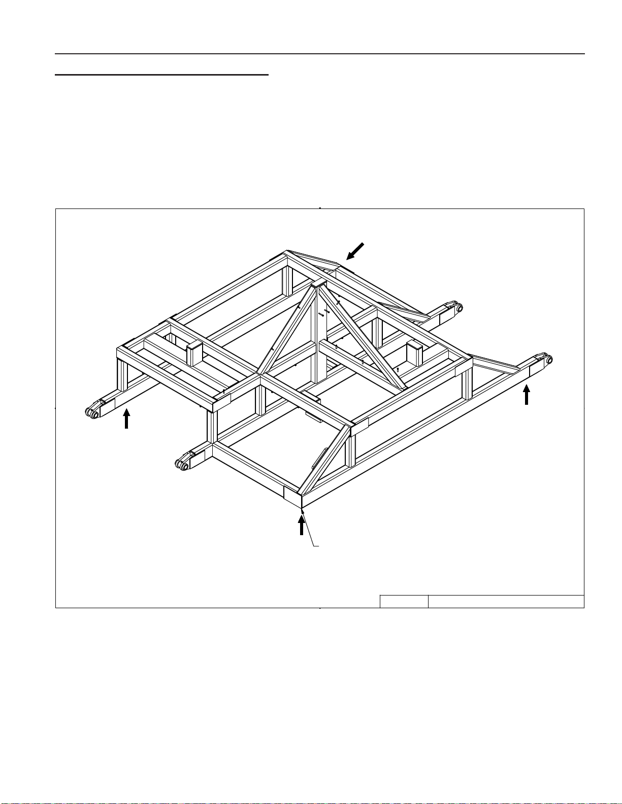
MF1. Position Main Frame on a at even surface. Set main frame on blocks or stands approxi-
mate 28 inches off ground in the locations shown in gure.
SUPPORT FOUR CORNERS OF FRAME WITH BLOCKS OR STANDS
3/15/2007
9LR3042.iam/
-10
2-3
Page 14
SECTION 2 - ASSEMBLY
1
2
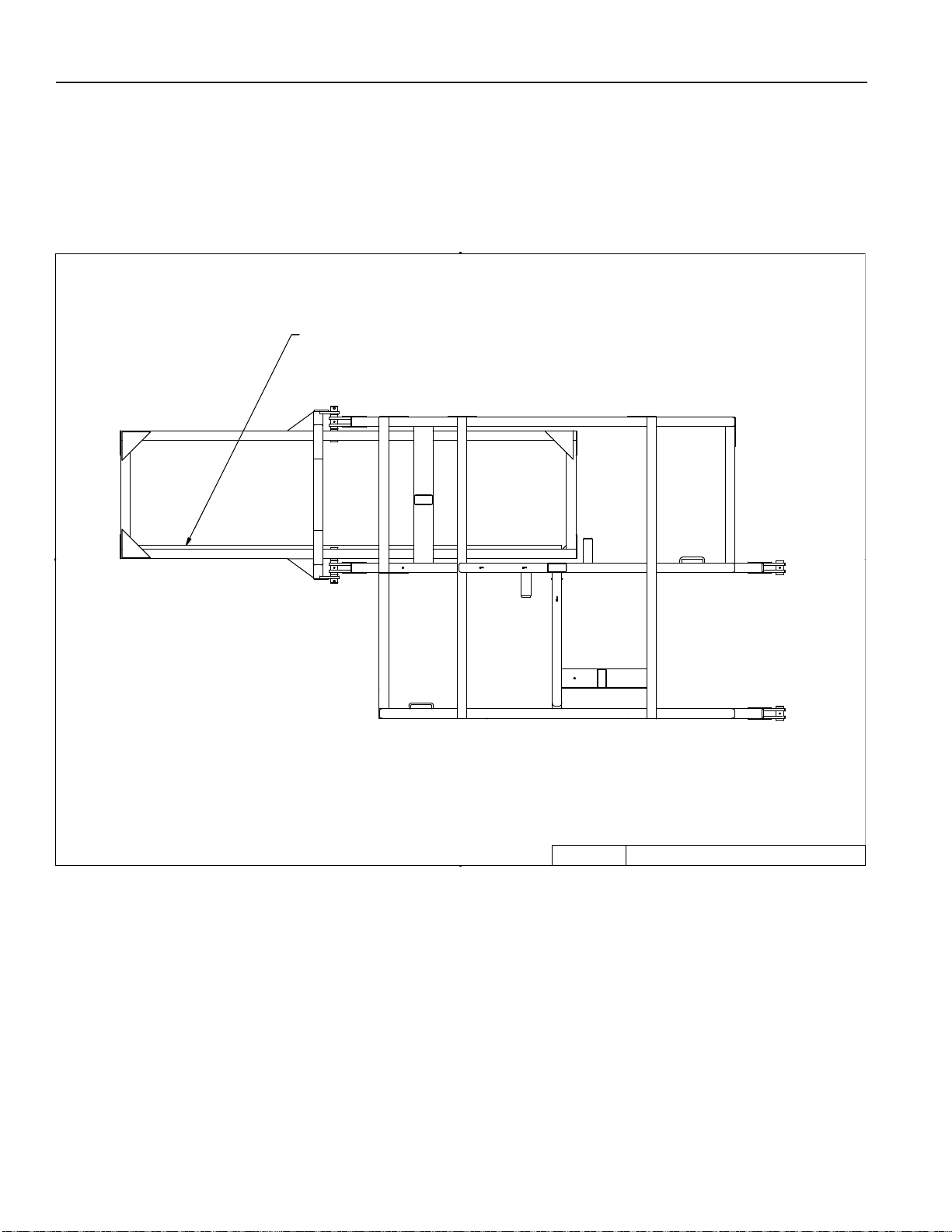
MF2. Position 8P6115L as shown in the drawing below. 8P6115L weighs 1166 lbs, use extreme
caution when positioning 8P6115L. Pay particular attention to the drawing to ensure that the
proper wing is installed on the appropriate side. When positioned properly as shown in gure
the correct orientation of the wing is determined by the mud scraper. The mud scraper should
be positioned towards the rear of the machine as show in gure below.
Figure 1
WINGS SHOULD BE POSITIONED SO SCRAPERS WILL BE TOWARDS THE REAR OF LANDROLLER
3/15/2007
9LR3042.iam/
-20
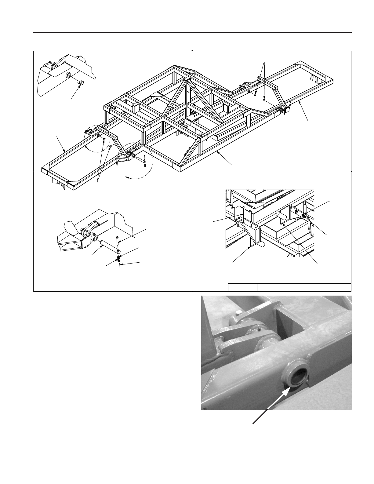
MF3. Install 2 8P3910 pins into the mating holes on the Main Frame. At this point the wing will be
free to pivot. Block wings after the pins have been installed to control unexpected movement.
2-4
Page 15
1
2
Figure 2
8P6115L
SECTION 2 - ASSEMBLY
8S3059
8S3059
8P6115R
C
B
8S3059
8X0095
8P3910
8X0304
8X0323
8X0253
MF4. Secure the pins with the hardware
shown in the drawing.
MF5. Repeat the above steps for 8P6115R.
MF6. Install Dust Caps, PN 8S3059, into the
locations shown in gure 2 and picture
P-W2.
8D0350
8P6030
8P6230
VIEW FROM BOTTOM
3/21/2007
9LR3042.iam/
8X0306
8X0260
8P6230
-30
MF7. Install 8P6230 as shown in gure 2.
Align from of 8P6230 with the face of the
tube and tighten the hardware. 8P6230
is the transport stop for the wing and
should be positioned with the round
shaft protuding past the tube to stop the
wing rotation.
P-W2
8S3059
PLUG
2-5
Page 16
SECTION 2 - ASSEMBLY
1
2
Roller Installation
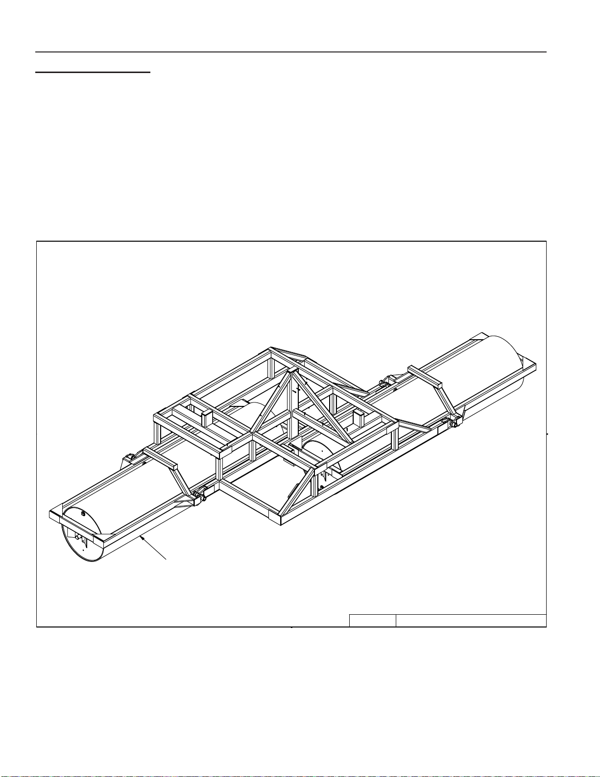
R1. Clean Roller Pivot shafts
R2. Elevate the wing frame and position roller under it. The wing frame will be free to pivot.
Block the wing frame to control unexpected movement. Center roller in the wing frame and
slowly lower the wing as shown in Figure 3. CAUTION: Each roller weighs 4285 lbs., block
to prevent unexpected movement. Be careful when moving the rollers, use extreme caution when centering the rollers and lifting the wing frames. NOTE: An H has been stamped
onto one end of each roller, position this H to the center of the Machine.
Figure 3
8P4215
NOTE: LOCATION OF H STAMPING TO BE TOWARDS THE CENTER OF MACHINE
3/15/2007
9LR3042.iam/
-40
2-6
Page 17
SECTION 2 - ASSEMBLY
1
2
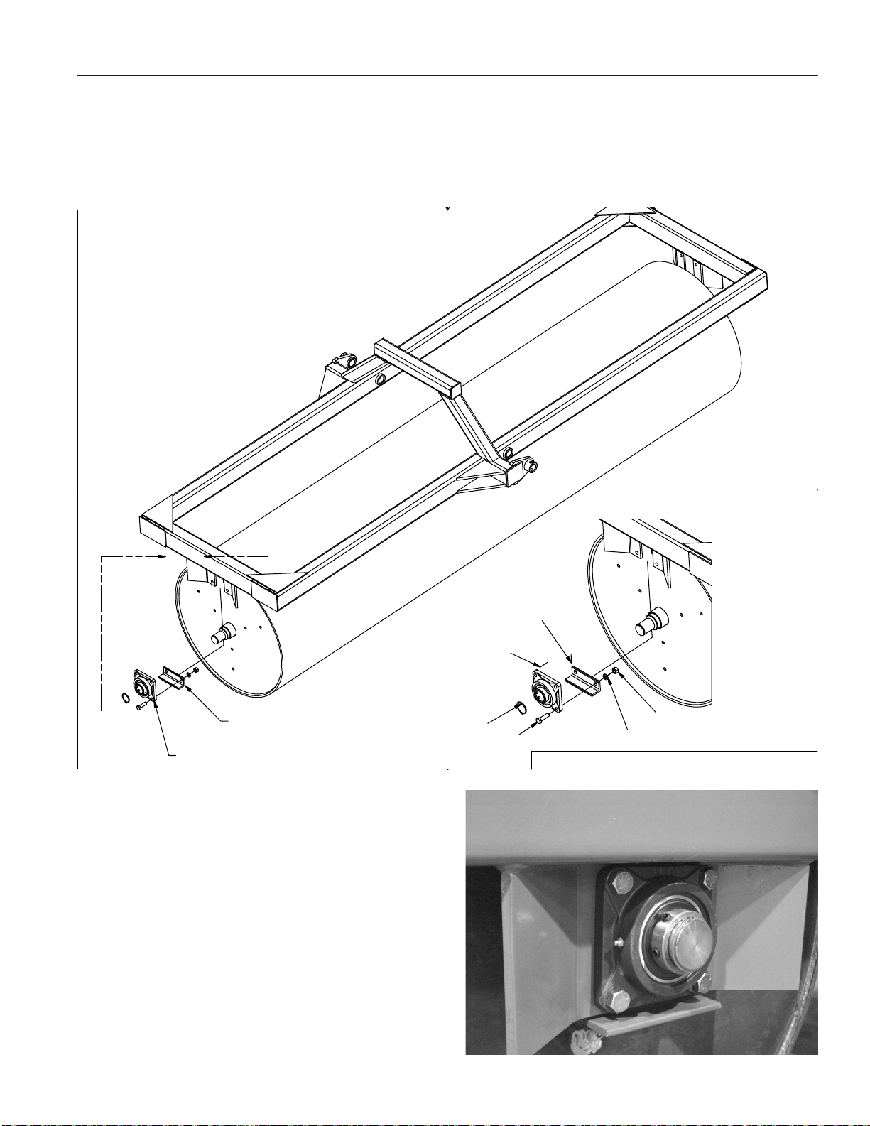
R3. Install bearing with grease zerks towards the rear of the machine. Secure to bolt plates
with hardware shown. Install reinforcement angles between the bottom attachment holes
on in the inside of the bolt plate. As shown in Figure 4.
Figure 4
A
8P5080 MOUNTS ON ROLLER SIDE
OF WING ATTACHMENT
8R8010 MOUNTS ON OUTSIDE OF WING ATTACHMENT
R 4. Install snap rings on each roller shaft.
Ensure that the roller is centered in the
bearings and tighten set screws.
R5. Repeat the above steps for the other roll-
er. Once the rollers have been installed
and all hardware has been tightened
remove all blocks and set the entire weight
of the machine on the rollers.
8R8010
8R8005
8X0111
8P5080
3/21/2007
8X0306
8X0265
9LR3042.iam/
-50
R6. Block rollers to ensure there is no unex-
pected movement.
2-7
Page 18
SECTION 2 - ASSEMBLY
Wheel and Pivot Arm Intallation.
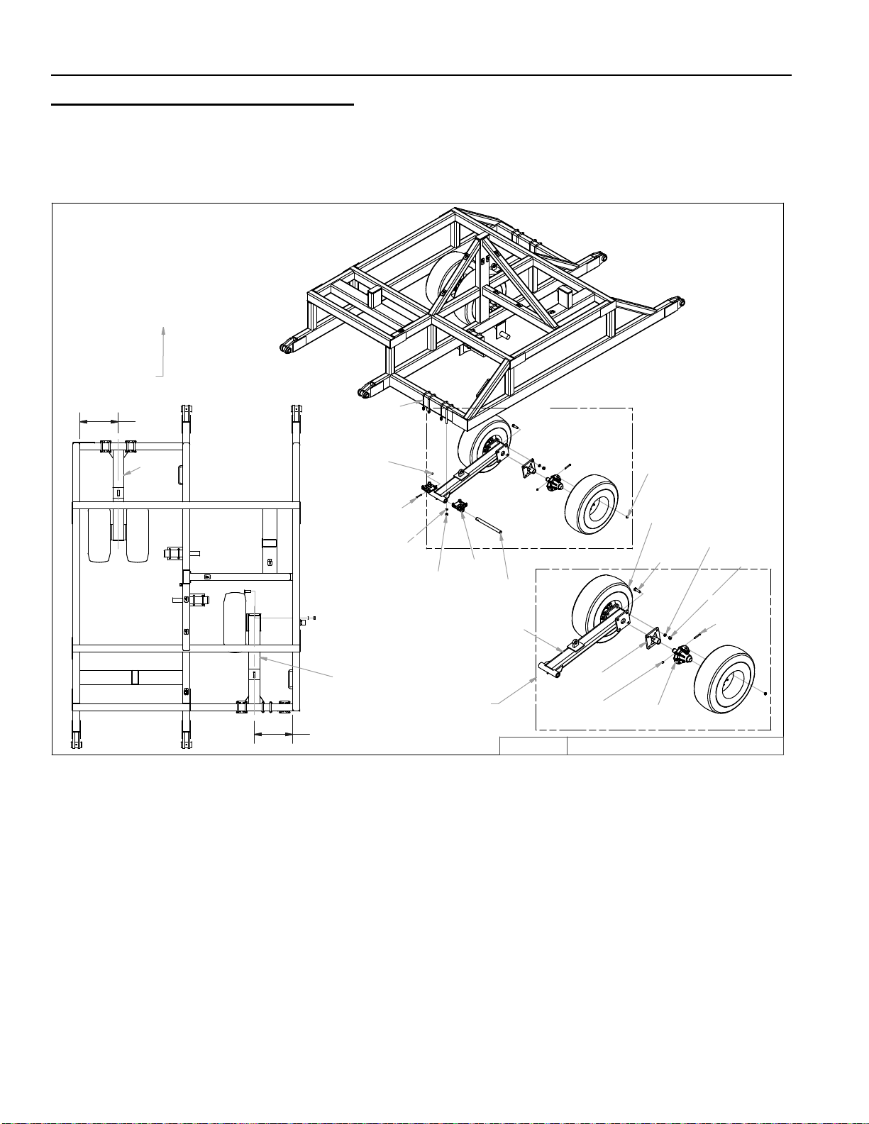
WP1. Locate 8P6110 and 8P6110S and install hub assemblies as shown in Figure 5. Secure hub
assemblies with the hardware shown.
Figure 5
TOWARDS
TRACTOR
21 1/2"
8P6110S
8D0350
3/4"X4-1/16" X10"
8X0234
7/16" LNUT
8K7123
8K7042
8X0133
7/8 X 3"
8K1105S
9LR3042.iam/
-70
8X0307
7/8" LW
8X0072
1/2" X 3-3/4"
8X0268
7/8" N
21 1/2"
8X0044
7/16" X 3-1/2"
8X0306
3/4" LW
8P6110
8T4100
8X0260
3/4" N
PRE-ASSEMB LE
BEFORE
ATTACHING TO
CENTER FRAME
8T3640
8P6110
8/27/2014
8P6105
8X0242
NY-LOCK 1/2" N
WP2. Install two wheels on each assembly. Torque wheel nuts to 240 FT-LB
WP3. Installtwo8T4100asshowningure.Looselyattachtotheframewith8D0350,lockwash-
ers and nuts. This will allow them to be moved and positioned when attached the pivot
arms.
WP4. PositionthePivotArmAssemblyandwheelsasshowningure.TheCenterofthearm
should be positioned to the dimension shown.
WP5. Installpin8T3640,alignholeinpinwiththeholein8T4100andsecurewiththehardware
shown.
WP6. TightenhardwarethatwasinstalledinWP3.(Makesurethecenterofthearmispositioned
to the dimension shown in Figure 5.)
WP7. RepeattheabovestepsfortheotherPivotArm.Refertothedrawingtoensuretheproper
pivot arm is installed in the correct location.
WP8 Looselyinstalltwo8P6215inthelocationsshowninFigure6,securewiththehardware
shown.
2-8
Page 19
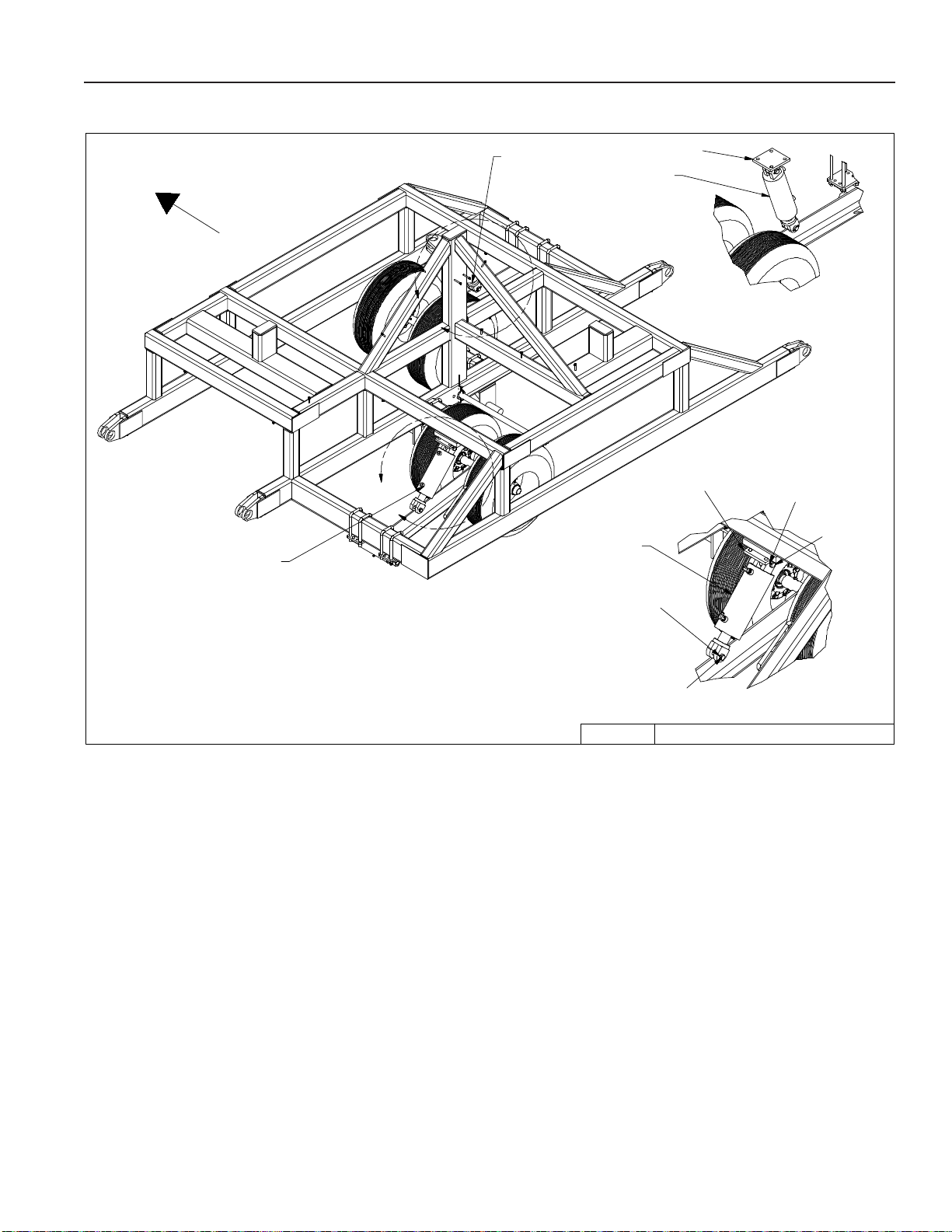
Figure 6
SECTION 2 - ASSEMBLY
TOWARDS
TRACTOR
8T1055
8T1050
B
A
8T1055
5.5" X 10"
8P6215
8T1050
5" X 10"
8P6215
8D9108
8K9106
8D9108
NOTE: WING AND ROLLERS (WHICH
WERE PREVIOUSLY INSTALLED) HAVE
BEEN EXCLUDED FROM THIS DRAWING
FOR EASE OF REPRESENTATION.
8K9106
-759/20/2010 9LR3042.iam/
WP9 Install the Lift cylinders as shown in Figure 6. Verify the correct location of the cylinders.
2-9
Page 20
SECTION 2 - ASSEMBLY
1
2
Hitch Installation
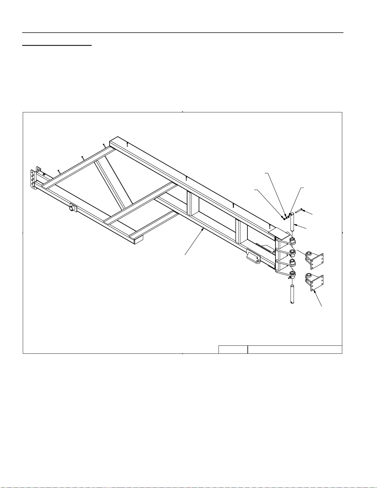
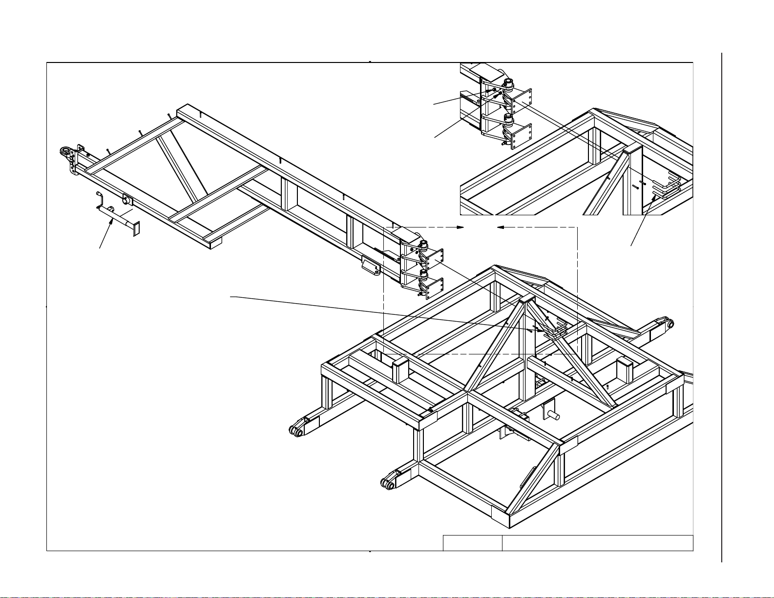
H1. Assemble two 8P6220 to the Hitch. Secure the 8P6220’s to the hitch with 8P3910. Align
hole in 8P3910 with the hole in 8P6220. Secure the pins with the hardware shown in Figure 7.
Figure 7
8X0304
LW
8X0253
LN
8X0323
FW
8X0095
8P3910
8P6000
4/2/2007
8P6220
9LR3042.iam/
-80
H2. Position hitch as shown in Figure 8. Secure the Hitch to the main frame with the Hardware
shown and as high on the main frame as possible. All U-bolts should be under the down
angle support tube.
2-10
Page 21
1
2
Figure 8
8X0260
8X0306
C
SECTION 2 - ASSEMBLY
8D8522
2-11
ALL U-BOLTS SHOULD BE
UNDER THE DOWN TUBE
8C1760
NOTE: WINGS, DRUMS, WHEELS,
PIVOT ARMS (WHICH WERE
PREVIOUSLY INSTALLED) HAVE BEEN
EXCLUDED FROM THIS DRAWING FOR
EASE OF REPRESENTATION.
4/3/2007
9LR3042.iam/
-90
Page 22
SECTION 2 - ASSEMBLY
1
2
Pivot Cylinder Installation
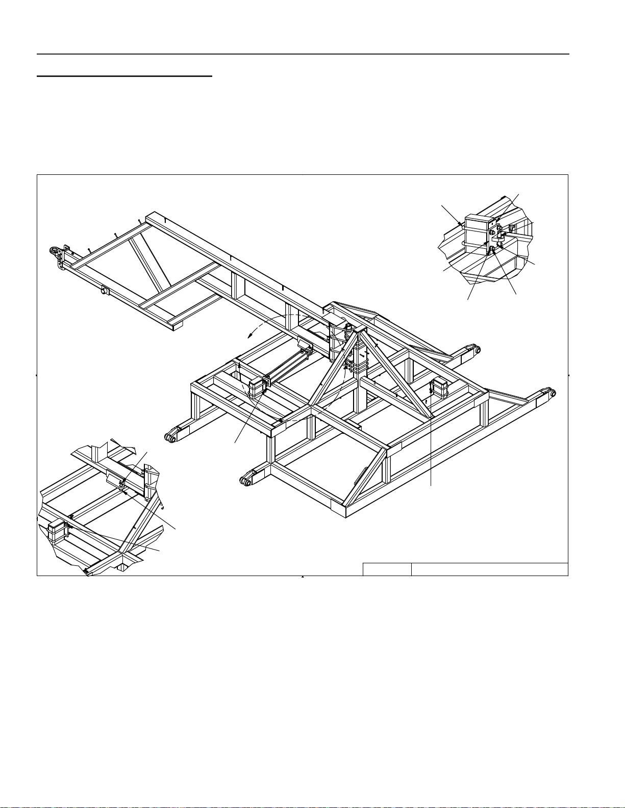
PC 1. Loosely attach 8P6210 (green) and 8P6211 (black) as shown in the drawing below. Please
note the installation location of each part as they are different. Attach with the hardware
shown in Figure 9.
Figure 9
NOTE: WINGS, DRUMS, WHEELS,
PIVOT ARMS (WHICH WERE
PREVIOUSLY INSTALLED) HAVE BEEN
EXCLUDED FROM THIS DRAWING FOR
EASE OF REPRESENTATION.
A
8K9102
8P6210
8D0350
8P6211
8X0306
8P6020
8K9102
8D9108
8X0260
8P6211
8D9108
8P6210
4/3/2007
9LR3042.iam/
-100
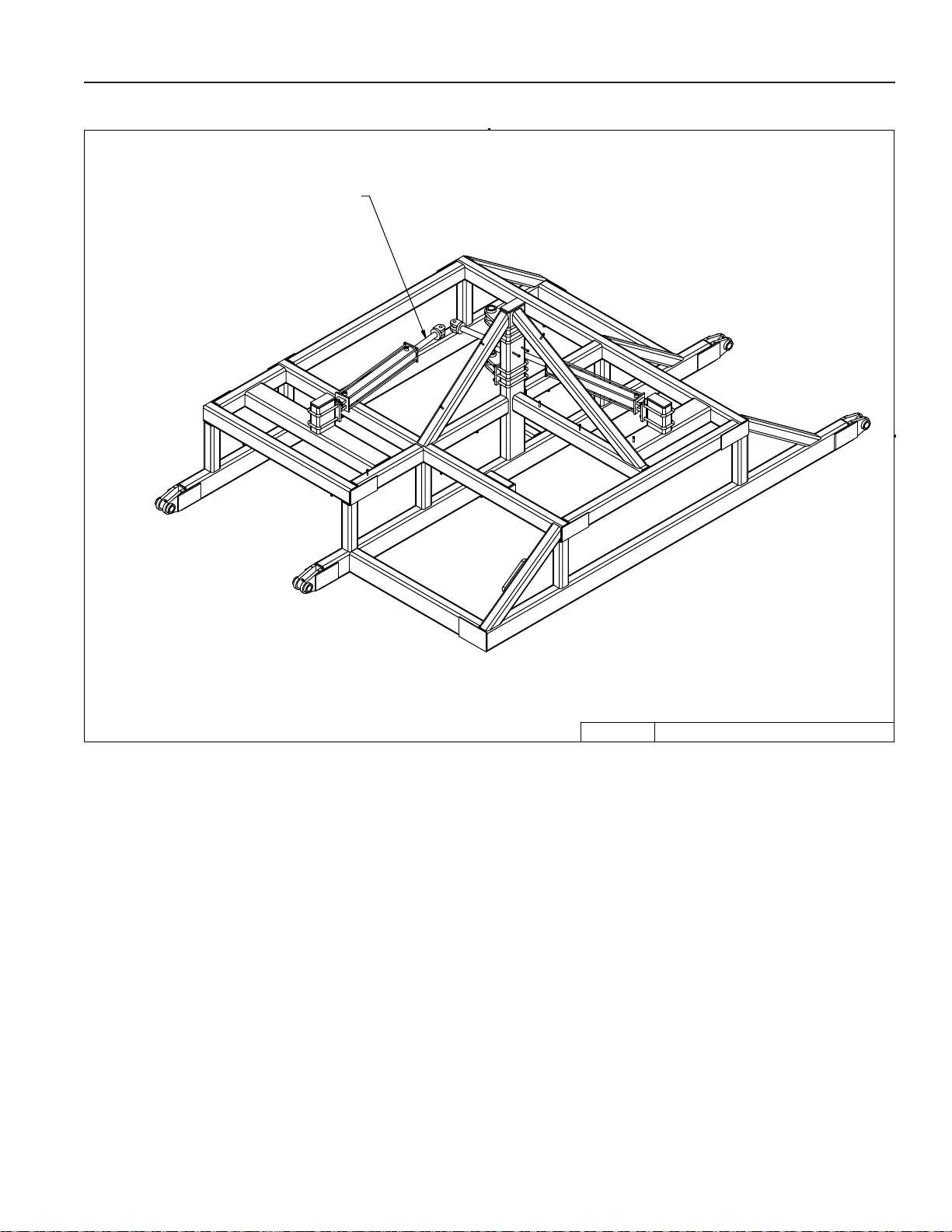
PC 2. Attach the bases end of the cylinders to each cylinder pivot with the hardware shown in Fig-
ure 9. Do not attach the rod end of the cylinder to the hitch at this point. The cylinders will
need to be plumbed to the hydraulic system and cycled to ll them with uid and remove
any air.
2-12
Page 23
1
2
Figure 10
DO NOT ATTACH ROD END OF CYLINDERS
TO HITCH UNTIL CYLINDERS
HAVE BEEN CYCLED 3 TIMES
SECTION 2 - ASSEMBLY
NOTE: WINGS, DRUMS, WHEELS,
PIVOT ARMS (WHICH WERE
PREVIOUSLY INSTALLED) HAVE BEEN
EXCLUDED FROM THIS DRAWING FOR
EASE OF REPRESENTATION.
4/3/2007
9LR3042.iam/
-110
PC3. Location and nal tightening of the hardware will be after the hydraulic cylinders have been
cycled.
2-13
Page 24
SECTION 2 - ASSEMBLY
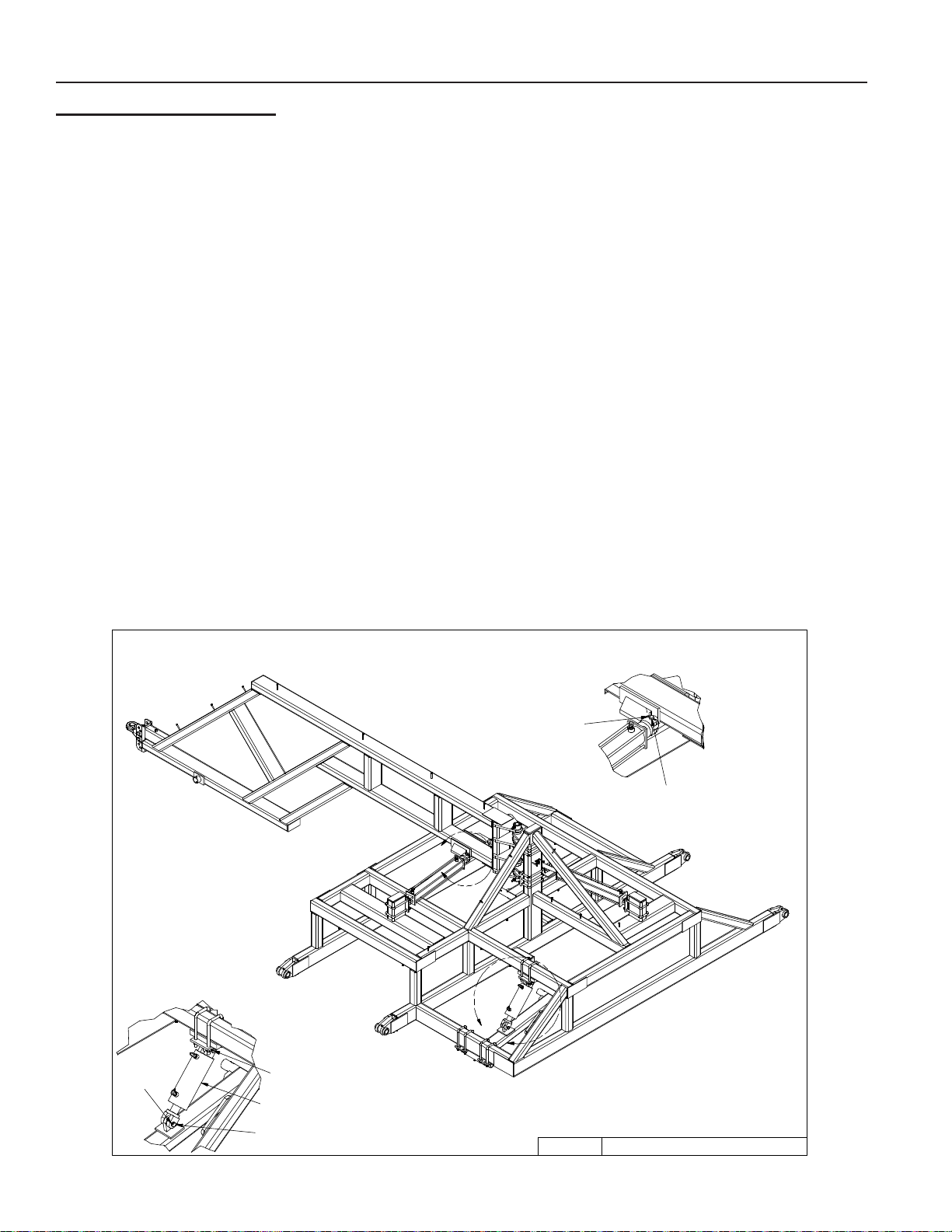
Hydraulic Installation
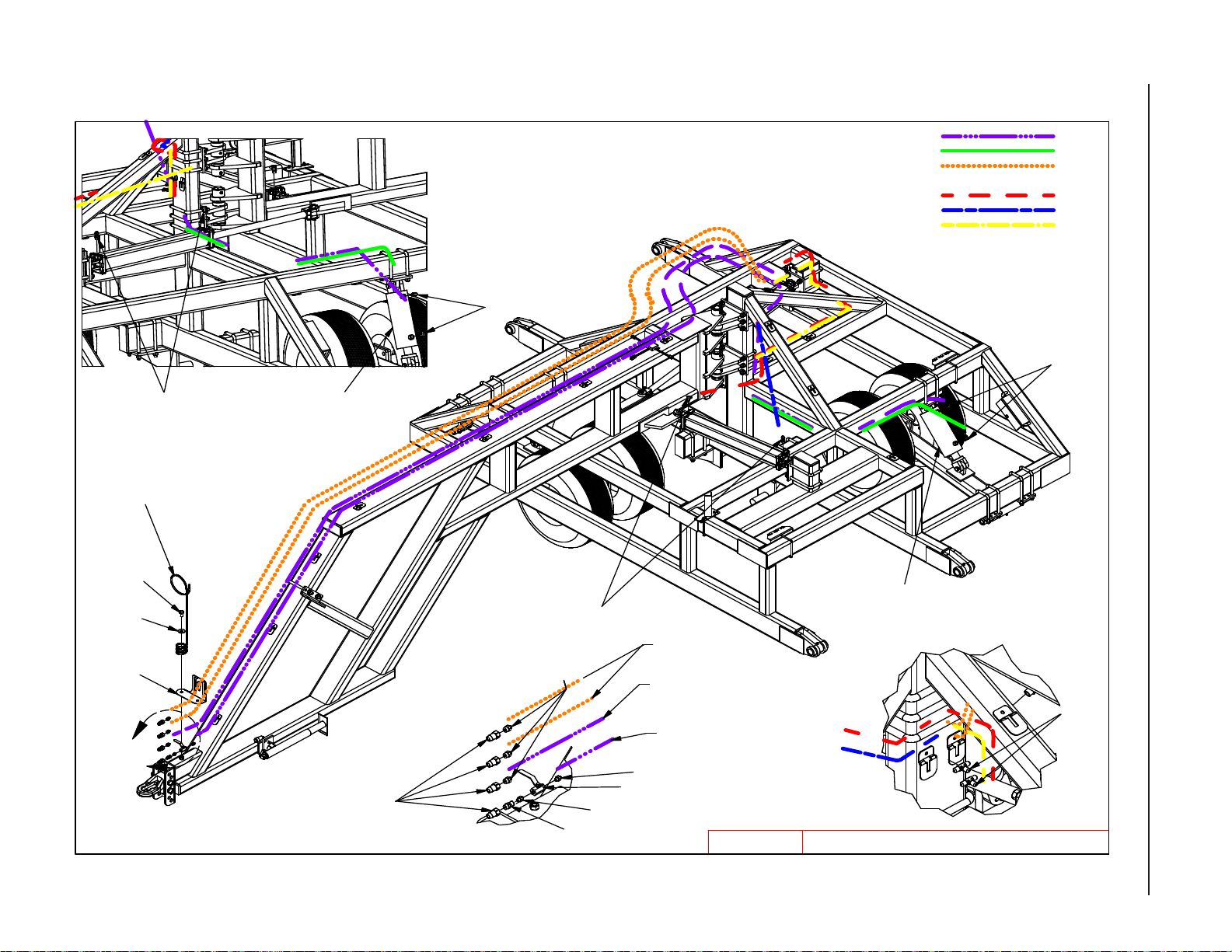
H1. Install Hydraulic components as shown in Figure 12 provided.
A. Leave enough slack at the hitch pivot to allow folding machine without stretching or
pinching hydraulic hoses.
B. Secure hoses with nylon ties and clamps provided. Do not over tighten clamps
H2. Block the hitch hydraulic cylinders so the rods can extend 32 inches without contacting any
obstructions. Fully extend and retract cylinders 3 times to insure all air is purged from the
cylinders.
H3. Fully retract the left cylinder, which will fully extend the right cylinders as shown in the draw-
ing below.
H4. Swing the hitch to the eld position. Transferring the weight of the hitch from the transport
to the eld position may cause the machine to shift. Use caution during this step.
H5. Install the pin in the rod end of the left cylinder. This will set the correct position of the hitch.
H6. Position the right cylinder to the hitch. At this point the hole in the rod end of the left cylin-
der may not line up with the hole in the hitch. Install the provided shims (8P6020) so the
hole in the rod of cylinder lines up with the hole in the hitch. The amount of shims used will
vary. Do not install so many shims that it pushes the hole in the rod of the cylinder past the
center of the hole in the hitch. Installing the pins with to many shims behind the pivot will
cause undo stress on the cylinder. It may be necessary to cycle the hydraulics a minimum
amount to get holes to line up perfectly.
H7. Level the cylinders and tighten the hardware on the pivots.
Figure 11
8D9108
8K9102
B
A
8D9108
8K9106
8T1055
8K9106
-1209/13/2010 9LR3042.iam/
2-14
Page 25
HYDRAULICS9/20/2010
9LR3042.iam/
A
8D8500
8J6010
8J6010
8X0110
8D3212
8J5510
8J5620
8J5500
8J7000
8J5500
8J5300
8J6010
8J6010
TO 5-1/2" BASE
TO 8J5300 (TEES)
5-1/2" ROD SIDE TO 5" BASE SIDE - 8N3160 (160") =
TRACTOR TO 8J5300 (TEES) 8N3348 (348") =
TRACTOR TO 5-1/2" BASE & TRACTOR TO 5" ROD - 8N3432 (432") =
TOP 8J5300 (TEE) TO ROD SIDE OF LEFT CYLINDER
& BASE SIDE OF RIGHT CYLINDER - 8N3048 (48") =
BOTTOM 8J5300 (TEE) TO BASE SIDE LEFT CYLINDER - 8N3060 (60") =
TO ROD SIDE OF RIGHT CYLINDER - 8N3124 (124") =
8T1055
8T1050
TO 5" ROD SIDE
8X0318
8D8490
2-15
Figure 12
SECTION 2 - ASSEMBLY
Page 26
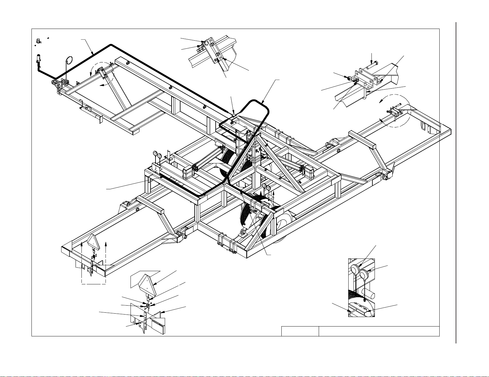
Figure 13 - Wiring and Safety Installation
2-16
8K8070B
A
LIGHT WIRING SHOULD
BE ZIP TIED TO SIDE
OF TUBE
8X0139
8X0281
8L1060
8K8030A
8P5070
C
8K8075A
8X0281
8X0260
8X0306
8X0143
8P5070
8D0340
B
SECTION 2 - ASSEMBLY
8K8210
D
8K8210
8K8210
8X0203
8S1120
8S1126
8K8210
8A1155
LIGHT WIRING SHOULD
BE RUN WITH
HYDRAULIC HOSE
ALONG BOTTOM
OF TUBE
8A1155
8K8095A
8K8090A
8K8020
SAFETY LIGHTS9/20/2010 9LR3042.iam/
Page 27

SECTION 3 – OPERATION
LAND ROLLER OPERATION SAFETY
1. READ AND UNDERSTAND Operator’s Manual before using machine. Review at least annually
thereafter.
2. VERIFY all safety devices and shields are in place before using machine.
3. KEEP hands, feet, hair and clothing away from moving parts.
4. STOP engine, place all controls in neutral, set parking brake, remove ignition key and wait
for all moving parts to stop before servicing, adjusting, maintaining or unplugging.
5. BE CAREFUL when working around high pressure hydraulic system.
6. ALWAYS make sure Land Roller is lowered into eld position, it is blocked to prevent movement
and that pressure is relieved from hydraulic circuits before servicing.
7. DO NOT ALLOW RIDERS.
8. USE EXTREME CARE when making adjustments.
9. KEEP CHILDREN AWAY from machinery at all times.
10. NEVER ALLOW anyone to work under Land Roller.
11. WARNING – DO NOT ATTEMPT to raise machine into transport position if mud has built up on
rollers or if machine weight has been increased by any other means. Mechanical failure may
occur.
STEPS PRIOR TO OPERATION:
1. COMPLETE WARRANTY REGISTRATION CARD.
A. Complete and return WARRANTY REGISTRATION CARD located at the beginning of this
manual. Returning this card entitles you to a free gift.
B. Complete the OWNER REGISTER also located at the beginning of this manual (Serial Num-
ber is located by the front of the hitch). Owner register information may be needed when
ordering parts.
2. VERIFY TRACTOR REQUIREMENTS.
A. WARNING: Land Roller must be attached directly to tractor drawbar and not an intermediate
towed vehicle or implement. Loss of control could result causing serious injury or death to
you or others.
B. Ability to safely operate the Summers Land Roller is determined by both tractor horsepower
and weight. The minimum tractor weight for operating this implement is 16,000 lbs. Minimum tractor engine horsepower is 125. Dual tires or single tires set at maximum width are
required for safe operation of the Land Roller.
C. The Summers Land Roller must be connected to a tractor drawbar with a locked draw pin.
The tractor drawbar must be able to withstand 2000 lb. of tongue weight during transport
and eld operation.
3-1
Page 28
SECTION 3 – OPERATION
INITIAL HOOKUP:
1. Make tractor to hitch connection with locking draw pin and safety chain.
2. Retract jack and rotate into storage position.
3. Plug Hitch Cylinder hoses into desired tractor outlet, adjust hydraulic ow rate to 35% of maximum.
Insure that tips and couplers are CLEAN.
4. Plug Lift Cylinder hoses into desired tractor outlet, adjust hydraulic ow rate to 35% of maximum.
5. Connect safety Light Kit wiring harness to 7 pin receptacle.
6. If Land Roller is in Transport Position, follow “Steps Required to Unfold from Transport to Field
Position”.
7. INITIAL CHECK – with machine in Field Position
A. After receiving or assembling your Land Roller, it is a good practice to double check the entire
machine so all fasteners are securely tightened.
B. Make sure all grease ttings are in place and greased properly.
C. Inate tires to recommended ination pressure (see page 4-2), check that wheel nuts are
tightened to 170 ft-lb and check that wheel bearings are correctly adjusted.
3-2
Page 29

SECTION 3 – OPERATION
STEPS REQUIRED TO UNFOLD FROM TRANSPORT TO FIELD POSITION:
1. WARNING: Land Roller must be attached directly to tractor drawbar and not an intermediate
towed vehicle or implement. Loss of control could result causing serious injury or death to you or
others. Never tow this implement with less than an 16,000 lb. vehicle
2. Ability to safely operate the Summers Land Roller is determined by both tractor horsepower and
weight. The minimum tractor weight for operating this implement is 16,000 lb. Minimum tractor
engine horsepower is 125. Dual tires or single tires set at maximum width are required for safe
operation of the Land Roller.
3. The Summers Land Roller must be connected to a tractor drawbar with a locked draw pin. The
tractor drawbar must be able to withstand 2000 lb of tongue weight during transport and eld operation.
4. Park tractor and Land Roller on a rm level surface with enough open area that will allow unfolding
Land Roller without contacting obstructions.
5. Unhook Hitch Pivot Safety Lock Chains. Hook Chains onto storage Rings located on the main
hitch. Open pivot lock hydraulic valve.
6. Operate tractor hydraulics from operator station only. Do not allow anyone to stand near the Land
Roller when folding or unfolding. Do not raise or lower Land Roller when implement is moving.
7. Place tractor in Neutral as the folding procedure may cause the tractor to roll.
8. Activate the lift cylinder hydraulic valve. Lower the machine completely to the ground; fully retract
lift cylinders so wheels rise off the ground.
9. Activate the hitch cylinder hydraulic valve. Fully cycle the pivot cylinders until the Land Roller no
longer rotates. During rotation the entire Land Roller may move to the right side of the tractor,
the tractor may also roll.
3-3
Page 30

SECTION 3 – OPERATION
LAND ROLLER FIELD OPERATION:
1. If Land Roller is in Transport Position, follow “Steps Required to Unfold Land Roller from Transport
to Field Position”, page 3-3.
2. Choose an operating speed which achieves desired results. Operating at over 7 MPH will decrease
effectiveness and increase chance of immovable rocks denting roller tube. Denting of roller tube
is NOT covered by warranty.
STEPS REQUIRED TO FOLD FROM FIELD TO TRANSPORT POSITION:
1. WARNING: Land Roller must be attached directly to tractor drawbar and not an intermediate
towed vehicle or implement. Loss of control could result causing serious injury or death to you or
others. Never tow this implement with less than an 16,000 lb vehicle.
2. The Summers Land Roller must be connected to a tractor drawbar with a locked draw pin. The
tractor drawbar must be able to withstand 2000 lb of tongue weight during transport and eld operation.
3. Park tractor and Land Roller on a rm level surface with enough open area that will allow folding
Land Roller without contacting obstructions. Operate tractor hydraulics from the operator station
only. Do not allow anyone to stand near the Land Roller when folding or unfolding.
4. WARNING: DO NOT ATTEMPT to raise machine into transport position if mud has built up
on rollers or if machine weight has been increased by any other means.
5. Activate the hitch cylinder hydraulic valve. Fully cycle the pivot cylinders until the Land Roller no
longer rotates. During rotation the entire Land Roller may move to the right side of the tractor.
The tractor may also roll.
6. Activate the lift cylinder hydraulic valve. Raise machine completely fully extending lift cylinders
so the rollers rise off the ground.
7. Install Hitch Pivot Safety Lock Chains and close pivot lock hydraulic valve.
3-4
Page 31
SECTION 3 – OPERATION
TRANSPORTING LAND ROLLER:
1. If Land Roller is in Field Position, follow “Steps Required to Fold Land Roller from Field to Transport Position”, page 3-4.
2. Ability to safely operate the Summers Superroller is determined by both tractor horsepower and
weight. The minimum tractor weight for operating this implement is 16,000 lbs. Minimum tractor
engine horsepower is 125. Dual tires or single tires set at maximum width are required for safe
operation of Land Roller.
3. ONLY TOW at a safe speed – 20 MPH MAXIMUM. Use caution when making corners or meeting
trafc.
4. USE Safety Lights and Safety Chain between tractor drawbar and implement hitch when transporting on public roads.
5. ALWAYS install hitch pivot transport safety chains and lift cylinder locks.
6. FOLLOW ALL local laws governing transporting of farm machinery.
7. Use additional caution and reduce speed when towing under adverse conditions, when turning
and when on unlevel surfaces.
8. Stay clear of overhead lines and other overhead obstructions.
9. Frequently check for trafc from rear, especially during turns.
3-5
Page 32

SECTION 3 – OPERATION
UNHOOKING LAND ROLLER FROM TRACTOR IN FIELD POSITION:
1. NEVER unhook Land Roller if positioned hydraulically between Field and Transport Position.
2. Choose a rm level surface.
3. With Land Roller in Field Position; shut off tractor, engage parking brake and relieve hydraulic
pressure by cycling remote lever.
4. Block rollers to prevent movement after hitch pin is removed.
5. Check that hitch pin is not bound with sideways or front to back pressure. If hitch pin is not free,
carefully reposition tractor.
6. Rotate jack into vertical position and extend jack until hitch piece lifts off tractor drawbar.
7. Disconnect wiring harness, hydraulic hoses and safety chain.
8. Recheck that hitch pin is free, if so, stand to the side of the hitch and remove hitch pin.
9. Carefully drive ahead.
UNHOOKING LAND ROLLER FROM TRACTOR IN TRANSPORT POSITION:
1. NEVER unhook Land Roller if positioned hydraulically between Field and Transport Position.
2. DO NOT ALLOW ANYONE TO WORK UNDER LAND ROLLER.
3. Choose a very rm level surface.
4. Block tires to prevent movement after hitch pin is removed.
5. Check that hitch pin is not bound with side or front to back pressure. If hitch pin is not free, carefully reposition tractor
6. Rotate jack into vertical position, place sturdy block under jack to distribute load over larger area
and extend jack until hitch piece just lifts off tractor drawbar.
7. Disconnect wiring harness, hydraulic hoses and safety chain.
8. Recheck that hitch pin is free, if so, stand to the side of the hitch and remove hitch pin.
9. Carefully drive ahead.
3-6
Page 33
SECTION 4 – MAINTENANCE
MAINTENANCE SAFETY
1. STOP engine, place all controls in neutral, set parking brake, remove ignition key and wait for all
moving parts to stop before servicing, adjusting or maintaining.
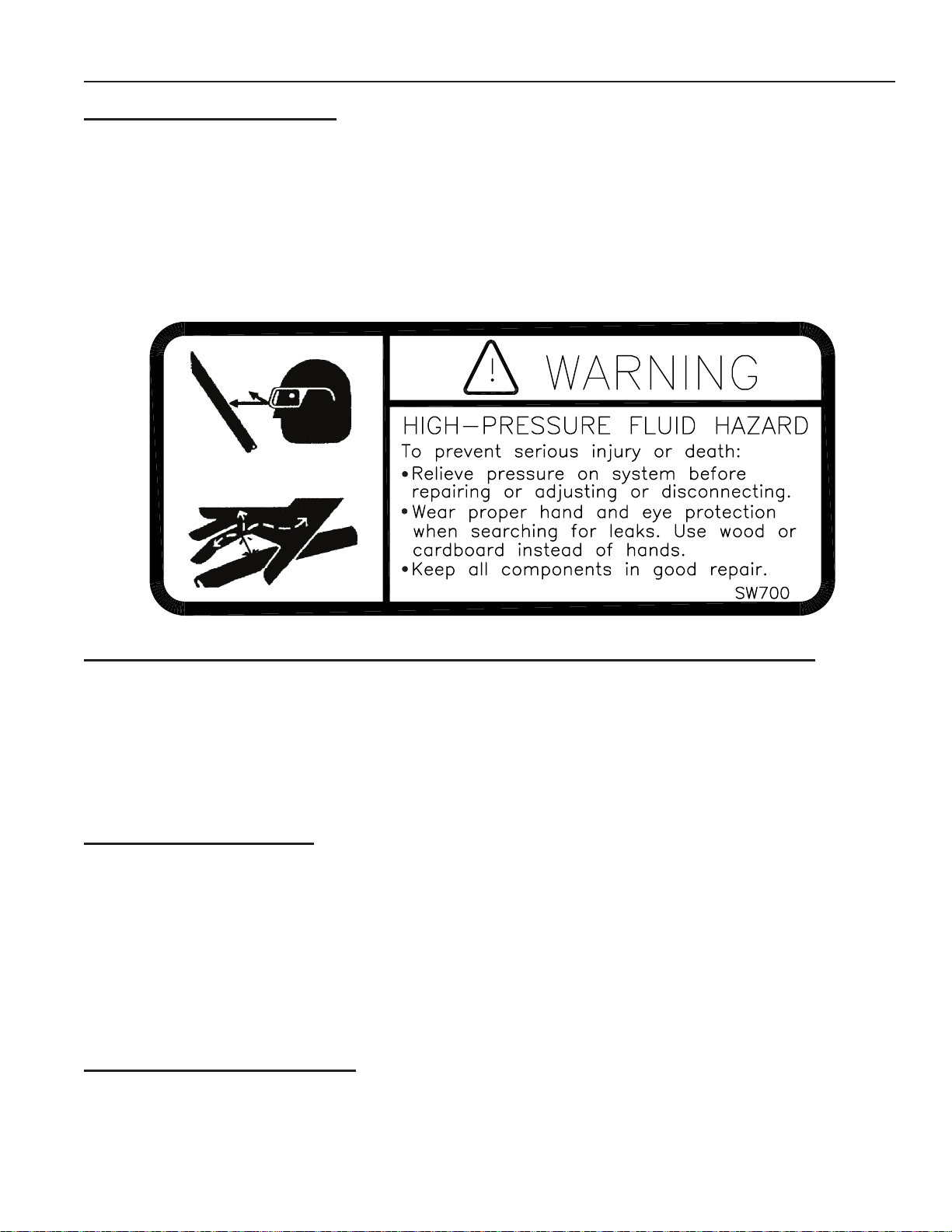
2. BE CAREFUL when working around high pressure hydraulic system.
3. ALWAYS make sure that Land Roller is lowered into eld position, it is blocked to prevent movement and pressure is relieved from hydraulic circuits before servicing.
4. USE EXTREME CARE when making adjustments.
5. KEEP CHILDREN AWAY from machinery at all times.
6. NEVER ALLOW anyone to work under Land Roller.
MAINTENANCE FOR AFTER THE FIRST FOUR HOURS OF OPERATION
1. Grease wing and hitch pivots.
2. Check all hydraulic components for leaks. (SEE HIGH-PRESSURE FLUID WARNING ABOVE.)
3. Check tightness of wheel nuts. Recommended torque 170 ft. lbs.
4. Check tightness of wheel bearings.
5. Check tightness of all hardware. Pay special attention to hitch and pivot pin retaining bolts.
6. Check tire pressures. Recommended air pressure is 90 PSI.
DAILY MAINTENANCE
1. Grease wing and hitch pivots.
2. Check all hydraulic components for leaks. (SEE HIGH-PRESSURE FLUID WARNING ABOVE.)
3. Check tightness of all wheel nuts. Recommended torque 170 ft. lbs.
4. Check tire air pressure. Recommended air pressure is 90 PSI.
ROLLER BEARINGS: To maximize bearing life, grease bearings at mid day or end of day when
bearings are at operating temperature. Every 20 hours: Add three strokes (approx. .14 oz.) of
grease.
PERIODIC MAINTENANCE
1. Repack wheel bearings and check tightness (See Page 5-6).
2. Check the tightness of all hardware. Pay special attention to hitch and pivot pin retaining bolts.
3. Check Land Roller for damaged or worn parts. Replace as needed.
4-1
Page 34

SECTION 4 – MAINTENANCE
STORAGE
1. Follow steps outlined in “UNHOOKING LAND ROLLER FROM TRACTOR IN FIELD POSITION”.
2. Clean and remove all excessive dirt and grease from Land Roller.
3. Grease all zerks.
4. To prevent rusting, repaint any areas that have been worn, chipped or scratched.
5. Apply grease* to any exposed part of cylinder shafts.
*NOTE: Before returning Land Roller into service, all grease must be removed from cylinder
shafts to prevent damage to seals.
SPECIFICATIONS
Working Transport Transport Transport Machine Roller
Width Width Height Length Weight Diameter
30’ 13’4” 9’11” 35’8” 18,600# 42”
Tire Size Rating Recommended Ination Pressure
12.5Lx15 LRF 90 PSI
Hub Size Rating Recommended Wheel Recommended Axle
Nut Torque Nut Torque
HD812 6100 LB. 170 ft.-lbs. 45 ft.-lbs., loosen until
20 MPH Maximum rst slot is aligned with
hole in axle, install cotter
pin, bend to retain.
4-2
Page 35

SECTION 5 – PARTS
REMEMBER TO BRING YOUR OWNER REGISTER INFORMATION LOCATED AT THE BEGINNING OF THIS
MANUAL WHEN ORDERING PARTS (SERIAL NUMBER
IS LOCATED BY THE FRONT OF THE HITCH).
5-1
Page 36
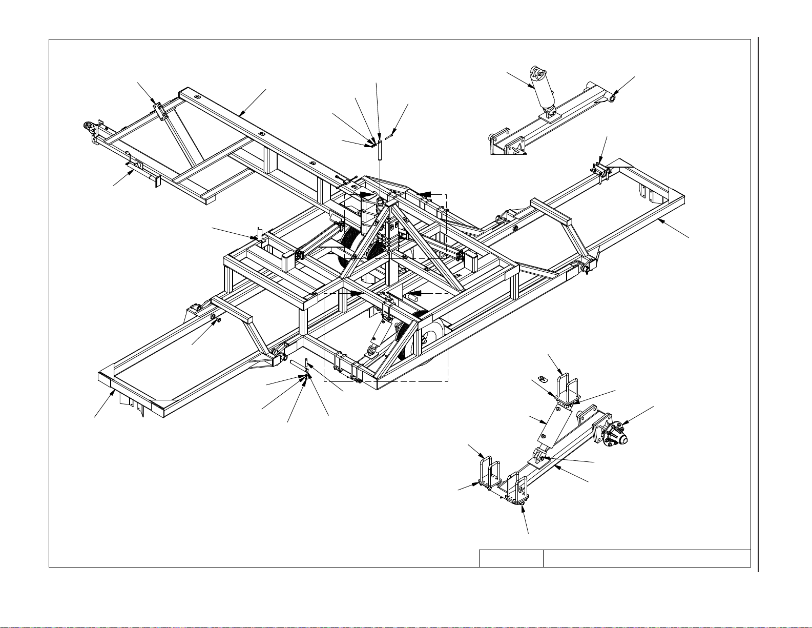
A
B
CENTER & HITCH10/9/2012 9LR3042.iam/
8X0253
8X0304
8X0323
8P3910
8X0095
8S3059
8P6115L
8D8522
8P6000
8P5070
8X0095
8P3910
8X0323
8X0304
8X0253
8P6030
8P6115R
8P5070
8K1105S
8P6110
8T1055
8P6215
8D0350
8D0350
8T4100
8T3640
8K9106
8K9106
8P6110S
8T1050
5-2
SECTION 5 – PARTS
Page 37
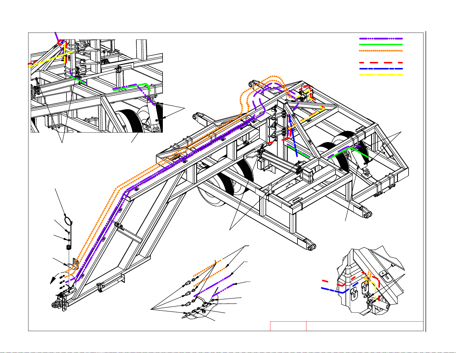
5-3
8J6010
8D8500
5-1/2" ROD SIDE TO 5" BASE SIDE - 8N3160 (160") =
TRACTOR TO 8J5300 (TEES) 8N3348 (348") =
TRACTOR TO 5-1/2" BASE & TRACTOR TO 5" ROD - 8N3432 (432") =
TOP 8J5300 (TEE) TO ROD SIDE OF LEFT CYLINDER
& BASE SIDE OF RIGHT CYLINDER - 8N3048 (48") =
BOTTOM 8J5300 (TEE) TO BASE SIDE LEFT CYLINDER - 8N3060 (60") =
TO ROD SIDE OF RIGHT CYLINDER - 8N3124 (124") =
8J6010
8J6010
SECTION 5 – PARTS
8T1050
8X0110
8X0318
8D8490
A
8D3212
8J5510
8J5620
8J6010
8J5500
TO 8J5300 (TEES)
TO 5" ROD SIDE
TO 5-1/2" BASE
8J5500
8J7000
8T1055
9LR3042.iam/
8J5300
HYDRAULICS9/20/2010
Page 38
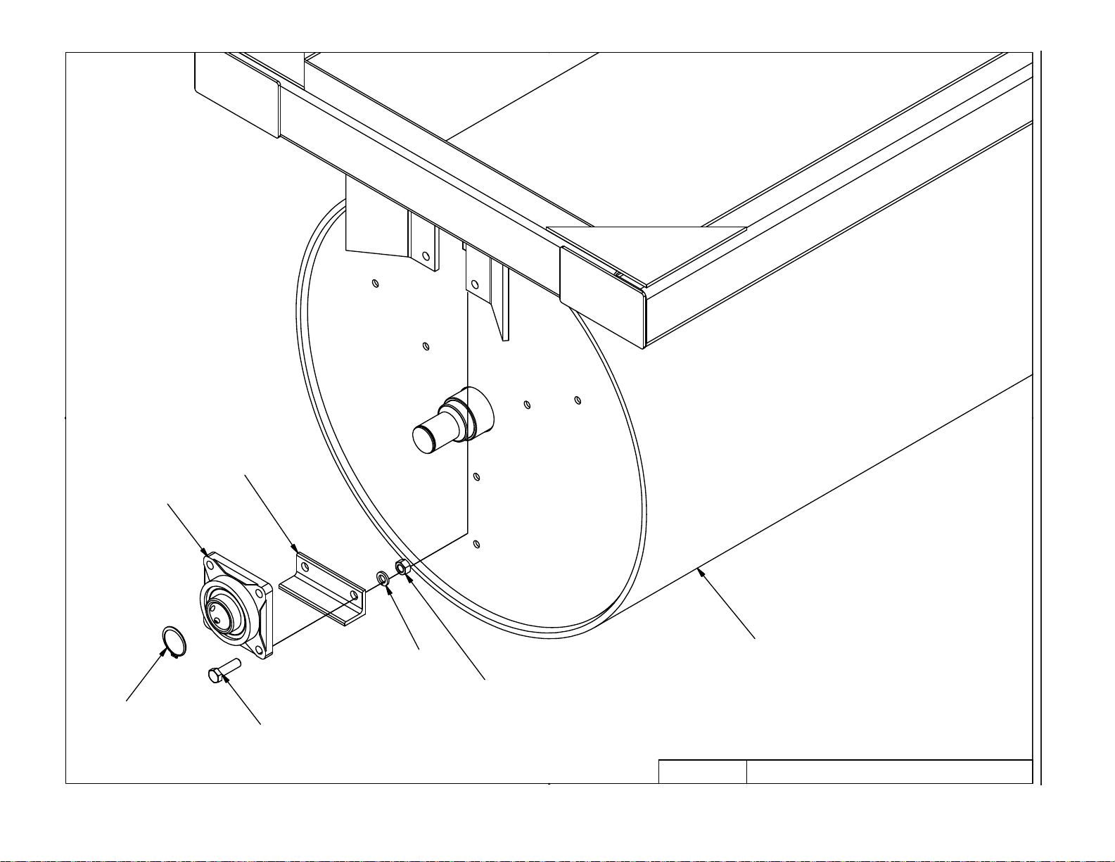
1
2
5-4
8R8010
8P5080
SECTION 5 – PARTS
8R8005
8X0111
8X0306
8X0265
4/3/2007
8P4215
9LR3042.iam/
WING & ROLLER
Page 39
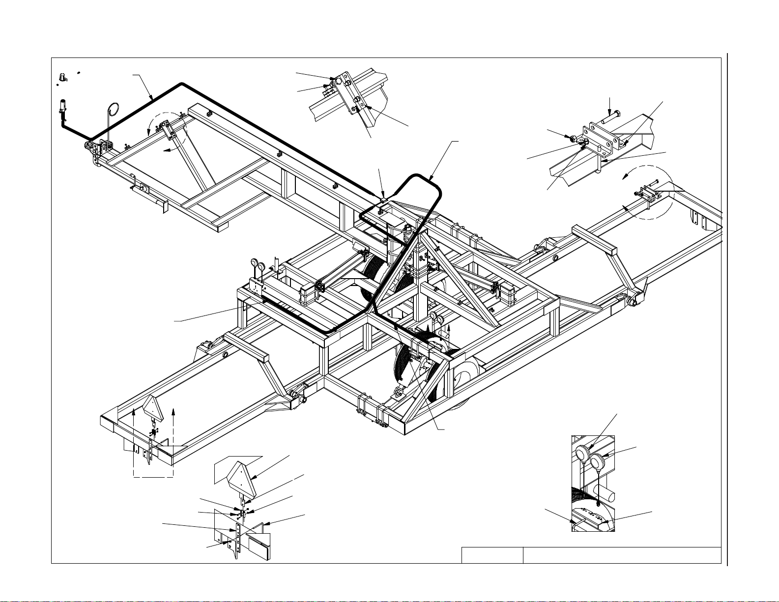
8K8070B
8X0139
8X0281
8X0281
8P5070
A
8L1060
8K8030A
8K8075A
8X0260
8X0143
8P5070
8D0340
5-5
LIGHT WIRING SHOULD
BE ZIP TIED TO SIDE
OF TUBE
D
8K8210
8K8210
8K8210
8S1120
8S1126
8K8210
8A1155
C
LIGHT WIRING SHOULD
BE RUN WITH
HYDRAULIC HOSE
ALONG BOTTOM
OF TUBE
8A1155
8X0306
B
SECTION 5 – PARTS
8K8095A
8K8090A
8K8020
8X0203
SAFETY LIGHTS9/20/2010 9LR3042.iam/
Page 40
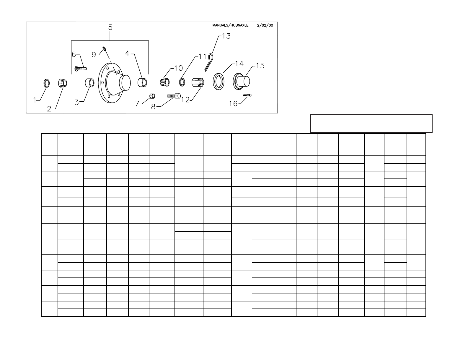
HVY
8R6914
-
*
2000
)
S
0
)
5-6
HUB 1. SEAL
H211
H517
H611
H614
HD812
HD817
H1010
H1010
H1020
Pre
** GBGI (Not Shown), 8R6921 Triple Lip (Shown
*** Pre 2006 8K7120 (SE17
8G8220 8G8217 8G8230 8G8230 8G8211
SE10 L44643 8L44610 L44610 HD WB10 1/4-28NF L44643 3/4" I.D. 3/4"- 16X1" DC11
8D5234
8D5236
8D5238
8D5221 8D5317 8D5334 8D5336
SE13 LM29749 LM29710 LM67010 H
8R6922** 8R6917 8R6925 8D5332 8R6911
SEE GBGI
INSTRUCTIONS
8K7127***
SEAL SE77
8K7128***
SLEEVE SE
8K7344 7K7342 8K7346 8K7347 8K7340 8K7122-5/8" 8K7123-5/8"
SE42 LM387AS 382A LM501310 HD817 WB46
8K7220 7K7217 8K7230 8K7232 8K7211 8K7215 8K7216
LT
SE48 39585 39520 453A H1010-9 WB51
8K7221 8K7219 8K7231 8K7232 8K7210 8K7215 8K7216
SE67 33275 33462 453A H1010-11 WB51
8K7320 8K7317 8K7330 8K7332 8K7209 8K7215 8K7216
SE55 HM218248 HM218210 HM212010 HDA1020 WB51
2. INNE
BEARINRG
8D5217 8D5332 8D5336 8D5210 8D5215 8D5214
LM48548 LM48510 LM67010 H517 WB16 1/ 1/4-28NF LM67048 7/8" I.D. 7/8"- X1-1/2" DC13
LM603049 LM603011 LM48510 H
8K7117 8K7130 8K7132
LM3780 LM3720 LM2720WHD812
77
1
3. INN
RACERE
4. OURATER
CE
5. HUB ASSY
A211
8D53
11 -09
8D53
16 10-
611
614
8K7111
6. WSHEEL
TUD
N/A N/A
N/A N/A
N/A
8K71
15-9/16"* 8K7116-9/16"*
8K7122-5/8" 8K7123-5/8"
B41
WB46 WB118
7. WHEEL
NUT
2-20UNF
N/A
WB40
WB118
WB52
WB52
WB52
HUB AND AXLE COMPONENTS
Assembly Notes:
A. Before towing machine, pack wheel bearings
and ll 1/2 of hub cavity with high quality bearing
grease.
B. Tighten axle nut to 45 ft.-lbs, loosen nut until rst
slot is aligned with hole in axle, install cotter pin and
bend to retain.
Legend:
SMC Part Number
INDUSTRY Part Number or Size
8. WHEEL
9. HUB
BOLT
8D5114 8X0708 8G8217 8D5119 8D5112 8X
N/A
8D5114
WB10 -09 8X0708 8D5117 8D5319 8D5312
WB12 10- 1/4-28NF LM67048 1" I.D. 1"-1 X1-1/2" DC13
8R6914 8X0708 8D5217 8D5319 8D5312
WB12 1/4-28NF LM48548 1" I.D. 1"-1 X1-1/2" DC15
N/A
N/A
N/A
N/A
N/A
10. OUT
ZERK
8X0708 8D5117 8S5219 8D5212 8X
8X0708 8K7118 8D5319 8X
1/4-28NF LM2790 1" I.D. 1"-1 X1-1/2"
8X0708 8K7343 8X0328 8D5314
1/4-28NF LM501349 1.312 I.D. 1-1/4" /4X2" DC26
8X0708 8K7218 8X0328 8D5314 8X0414 8K7212 8K7213 8K7214
1/4-28NF 460 1.312 I.D. 1-1/4"-12 1/4X2" SE49 DC27 WB53
8X0708 8K7218 8X0328 8D5314 8X0414 8K7212 8K7213 8K7214
1/4-28NF 460 1.312 I.D. 1-1/4"-12 1/4X2" SE49 DC27 WB53
8X0708 8K7318 8X0366 N/A 8X0418 8K7312 8K7313 8K7214
1/4-28NF HM212049 2.03" ID 2" - 160 5/16 X 2-1/2" SE59 DC28 WB53
CD2\MANUALS\10 2-26 HUB-AXLE COMPONENT
BEARIERNG
11. A
WAS
XLE
HER
12. AX
LE 13. COTTER
NUT
16 3/
14 3/16
4 3/16
4 3/16
8D5312
4
-12 1
PIN
8X0415
8X0415
3/16
8X0414
14. HUB
CAP
G
ASKET
0410 8G8213 N/A
0415
0415
LAST REVISION: 3/2/201
N/A
N/A
N/A
N/A
N/A
N/A
15. HUB
CAP
8D5213
8D5213
8R6913
8K7113
DC17
8K7341
16. HUB
SECTION 5 – PARTS
CAP
BOLT
N/A
N/A
N/A
N/A
N/A
Page 41
SUMMERS MFG. CO., INC.
3/21/12
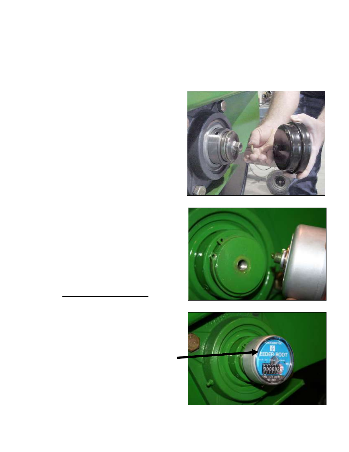
INSTALLATION AND OPERATION INSTRUCTIONS
FOR 8K1800
ACRE METER FOR SUPERROLLER
1. If Roller Shaft is not tapped, weld ½”-20
UNF nut at center of left pivot shaft of
middle roller. Position external taper of nut
toward shaft. Insure that threads are not
damaged by weld heat or spatter. Allow
weld to cool.
2. Attach Acre Meter with ½” lock washer.
Tighten to 260-390 in-lbs.
* For accurate logging of acres, it is important
that meter is mounted concentrically on
roller shaft.
* Do not use chemical agents such as thinner,
solvents or mineral spirits to clean Acre
Meter cover.
* Do not attempt to open meter! Attempting
to do so can cause injury and may destroy
Acre Meter.
CONVERSION FACTOR
NOTE: METER READING MUST BE
MULTIPLIED BY CONVERSION FACTOR FOR
ACTUAL ACRES.
MACHINE WIDTH FORMULA
30’ READING x 2.7 = ACRES
41’ READING x 3.6 = ACRES
45’ READING x 4 = ACRES
46’ READING x 4.1 = ACRES
50’ (36”) READING x 3.8 = ACRES
53’ READING x 4.7 = ACRES
62’ READING x 5.5 = ACRES
84’ (36”) READING x 6.5 = ACRES
84’ (42”) READING x 7.5 = ACRES
5-7
Cd1\8k\8k1800
Page 42

Stock Code Description
8A1155 U-BOLT 3/8 X 6-1/16 X 5” SQ
8A4048 NYLON TIE .18 X 11”
8A4050 NYLON TIE .30 X 8-7/8”
8A4052 NYLON TIE .30 X 15-1/4”
8C0270 SPLITSTEELBUSH1.375ODX1”ID-1”
8C0432 HYD CYLINDER 4” X 32”
8C1760 U-BOLT 3/4 X 8 X 6” SQ
8C1780 U-BOLT 7/8 X 8 X 10” SQ
8D0330 U-BOLT 5/8 X 6-1/16 X 5-5/8”SQ
8D0340 U-BOLT 3/4 X 4 X 7-3/4” SQ
8D0350 U-BOLT 3/4 X 4 X 10” SQ
8D0720 HITCH PIECE CAST CAT.3CTD PNTD
8D0722 PERFECT HTCH BACKSTOP W/HDWE
8D0724 CLEVIS OPT.HITCH CAT.3CTD998D0730 URETHANE CUSHION PERFCTHTCH
8D2440 SAFETY CHAIN 11000#X 84”
8D2460 SAFETY CHAIN 3/8” X 4’ 20200#
8D2470 SAFETY CHAIN 7/16” X 5’ 30400#
8D3212 MALE TIP 3/4”-16 ORB ISO
8D5314 NUT HEX SLOT 1.25”-12 GR2 PLN
8D8490 PIONEER/ISO TIP HLDR BNT 978D8500 HYD HOSE HOLDER PNTD BLK 918D8522 JACK 5000# TOP CRANK 15”LIFT
8D9102 PIN 1 X 4” CYL CTTR OR HAIRPIN
8D9108 ROLL PIN 1/4 X 2” YLW ZNC
8G2284 NYLON TIE .187 X 7-1/2” YELLOW
8G2285 NYLON TIE .187 X 7-1/2” GREEN
8J5100 #6 JIC(M) X #6 JIC(M) UNION
8J5110 #10 JIC(M) X #10 JIC(M) UNION
8J5200 #10 JIC(F) X #6 JIC(M)HEX BUSH
8J5300 #6 JIC (MALE) 3X TEE
8J5310 #10 JIC (MALE) 3X TEE
8J5500 9/16”-18 ORB X #6 JIC(M) STR
8J5510 3/4”-16 ORB X #6 JIC(M) STR
8J5520 3/4”-16 ORB X #10 JIC(M) STR
8J5600 9/16”-18 ORB X #6 JIC(F-SW)STR
8J5620 3/4”-16 ORB X #6 JIC(F-SW)STR
8J5680 3/4”-16 ORB X 3/4”-16ORB UNION
8J5690 3/4-16X3/4-16 ORB M-SW90*UNION
8J5700 #6 JIC(F-SW) X #6 JIC(M)90*ADP
8J5710 #10 JIC(F-SW)X#10 JIC(M)90*ADP
8J6010 3/4” -16 ORB X #6 JIC(M)90*ADP
8J6020 3/4”-16 ORB X #10 JIC(M)90*ADP
8J6060 3/4”-16ORB X #6JIC(F-SW)90*ADP
8J7000 BALL VALVE HYD 9/16”-18ORB(2X)
8J7040 THERMAL RELIEF MANIFLD 4000PSI
8J7116 3/4”-16 ORB(2X)1WAY 1/16”RESTR
8J7216 #6JIC(M)X6JIC(F)1/16”RSTR GOLD
8J7232 #6JIC(M)X6JIC(F)1/32”RSTR SLVR
8K1105S HUB&AXLE ASSY HD812 (2”RCVR)
8K5350 SPLITSTEELBUSH 2”ODX1.5”ID- 2”
8K5515 U-BOLT 3/4 X 4 X 6” SQ
8K7020 WHEEL 15 X 10” 8 BOLT-VLV GRD
8K7028 TIRE 12.5L X 15” LRF TL HWYSRV
8K7042 12.5L X 15” LRF ON 8 BLT WHEEL
8K7111 HUB HD812 W/CUPS&ZRK 8BLT3LIP
8K7113 HUB CAP HD812 DC17
8K7117 BEARING INNER HD812 LM3780
Stock Code Description
8K7118 BEARING OUTER HD812 LM2790
8K7120 SEAL 2-1/2”ID HD812 SE17 -06
8K7122 STUD WHEEL 5/8-18UNFX2.5”978K7123 NUT WHEEL BOLT 5/8-18UNF 978K7127 SEAL TRPL LIP EXTRNL HD812 068K7128 SEAL SLEEVE FOR 3X LIP 812 068K7130 RACE INNER HD812 LM3720
8K7132 RACE OUTER HD812 LM2720
8K7150S AXLE HD812X 11.5” (2”DIA.RCVR)
8K8000 FLAT LGHT BRCKT3/8X3.5-11.38”
8K8010 TUBE LGHT BRCKT1.5SQ55.5”008K8020 MOUNTNG BRCKT LIGHT 008K8060 EXT HRNSS 12’ 3PIN WTHRPCK -07
8K8067 DUST CAP FOR 7PIN CONNECT008K8068 MAIN HRNSS7PIN WTHRPCK SHRT-07
8K8070 MAIN HRNSS7PIN WTHRPCK LONG-07
8K8075 EXT HRNSS NONDRAWBR WPCK 00-07
8K8088 LENS ONLY AMBER GROTE LGHT 008K8090 LIGHT AMBER 2WIREWTHRPCK 00-07
8K8092 LENS ONLY RED GROTE LIGHT 008K8094 LIGHT RED 2WIRE WTHRPCK 00-07
8K8095 LIGHT RED 3WIRE WTHRPCK 058K8200 BRCKT SMV ATTCH 4-8”FRAME988K9102 PIN 1 X 4” CYL-FOR1/4”ROLL PIN
8K9106 PIN 1-1/4 X 4-3/8” HARDENED
8L1060 QUICKLINK 3/8” ZDI
8N3018 3/8X 18”HYD HOSE #6FJX3000PSI
8N3028 3/8X 28”HYD HOSE #6FJX3000PSI
8N3035 3/8X 35”HYD HOSE #6FJX3000PSI
8N3048 3/8X 48”HYD HOSE #6FJX3000PSI
8N3060 3/8X 60”HYD HOSE #6FJX3000PSI
8N3070 3/8X 70”HYD HOSE #6FJX3000PSI
8N3084 3/8X 84”HYD HOSE #6FJX3000PSI
8N3096 3/8X 96”HYD HOSE #6FJX3000PSI
8N3124 3/8X 124”HYD HOSE #6FJX3000PSI
8N3136 3/8X 136”HYD HOSE #6FJX3000PSI
8N3150 3/8X 150”HYD HOSE #6FJX3000PSI
8N3156 3/8X 156”HYD HOSE #6FJX3000PSI
8N3160 3/8X 160”HYD HOSE #6FJX3000PSI
8N3180 3/8X 180”HYD HOSE #6FJX3000PSI
8N3204 3/8X 204”HYD HOSE #6FJX3000PSI
8N3216 3/8X 216”HYD HOSE #6FJX3000PSI
8N3228 3/8X 228”HYD HOSE #6FJX3000PSI
8N3252 3/8X 252”HYD HOSE #6FJX3000PSI
8N3288 3/8X 288”HYD HOSE #6FJX3000PSI
8N3312 3/8X 312”HYD HOSE #6FJX3000PSI
8N3330 3/8X 330”HYD HOSE #6FJX3000PSI
8N3348 3/8X 348”HYD HOSE #6FJX3000PSI
8N3360 3/8X 360”HYD HOSE #6FJX3000PSI
8N3390 3/8X 390”HYD HOSE #6FJX3000PSI
8N3432 3/8X 432”HYD HOSE #6FJX3000PSI
8N3462 3/8X 462”HYD HOSE #6FJX3000PSI
8N3534 3/8X 534”HYD HOSE #6FJX3000PSI
8N3570 3/8X 570”HYD HOSE #6FJX3000PSI
8N3606 3/8X 606”HYD HOSE #6FJX3000PSI
8N4016 1/2X 16”HYD HOSE#10FJX3000PSI
8N4060 1/2X 60”HYD HOSE#10FJX3000PSI
8N4114 1/2X 114”HYD HOSE#10FJX3000PSI
5-8
Page 43

Stock Code Description Stock Code Description
8N4120 1/2X 120”HYD HOSE#10FJX3000PSI
8N4138 1/2X 138”HYD HOSE#10FJX3000PSI
8N4198 1/2X 198”HYD HOSE#10FJX3000PSI
8N4216 1/2X 216”HYD HOSE#10FJX3000PSI
8N4228 1/2X 228”HYD HOSE#10FJX3000PSI
8N4546 1/2X 546”HYD HOSE#10FJX3000PSI
8N4624 1/2X 624”HYD HOSE#10FJX3000PSI
8P3010 PLUG 2-1/2” NPT SQUARE HD STL
8P3500 TUBE 2-1/4ODX 1.268ID- 2-1/4”
8P3900 PIN 2 X 11-1/8” HARDENED
8P3910 PIN 2 X 13-1/2” HARDENED
8P4215 ROLLER 42”DIAMETER 15’ 058P5070 ANGL WNG LCK 1/2X3X3.5- 10.25”
8P5080 ANGLE BRNG 3/8X2.5X2.5- 7-7/8”
8P6000 HITCH 30’ SWING FOLD LR 068P6020P FLAT 10 GA 5”X8” PAINTED 078P6030 CENTER 30’ SWING FOLD LR 068P6100 LIFTARM W/RCVR SWNGFLD 068P6100S LIFTARM W/RCVR SWNGFLD SHRT068P6115L WING 15’-30’ SWNG FLD LEFT 068P6115R WING 15’-30’ SWNG FLD RGHT 068P6210 CYL ATTCH U-BLT ON 1” ID 068P6211 CVL ATTACH U-BOLT ON 1”ID 068P6215 CYL ATTCH U-BLT ON 1-1/4”ID068P6220 PIVOT HTCH SWNG FLD U-BLT 068P6230 STOP W/RND U-BLT SWNG FLD 068R6808 SPLITSTEELBUSH1.25 X 1”ID-.75”
8R6810 SPLITSTEELBUSH1.62X1.25”ID- 1”
8R8005 SNAP RING .078”FOR 2-1/2”DIA.
8R8010 BEARING 2-1/2”FLNG 4BLT-49/64”
8S1120 SIGN SLOW MOVING VEHICLE
8S1124 MOUNTING SOCKET SMV SIGN ZDI
8S1126 MNT SPADE W/HRDWR SMV SIGN
8S2980 HYD HOSE CLAMP-SMALL-NYLON
8S2990 HYD HOSE CLAMP-LARGE-NYLON
8S3059 CAPLUG FITS 2.067”ID TUBE
8T1050 HYD CYL 5.0 X 10” REPHASE 968T1055 HYD CYL 5.5 X 10” REPHASE 968T1150 SEAL KIT 5.0 X 10” RAM 988T1155 SEAL KIT 5.5 X 10” RAM 988T2986 CLAMP 1/2” WIRING MTL/RUB BCK
8T3640 PIN 1-1/2 X 19” HARDEND 988T4100 PIVOT W/BLTPLATE LIFTARM 968T4350 LOCK CYLINDER 10.5”(2.5ROD)968T5345 SPLITSTEELBUSH2”ODX1.5”ID-1.5”
8X0000 BOLT 1/4-20X3/4”FLLTHDGR5 ZDI
8X0000B BOLT 1/4-20NC X 1” GR5 ZDI
8X0001 BOLT 3/8-16NC X 3/4” GR5 ZDI
8X0002 BOLT 3/8-16NC X 1” GR5 ZDI
8X0003 BOLT 1/4-20NC X 4-1/2” GR5 ZDI
8X0004 BOLT 3/8-16NC X 1-1/4” GR5 ZDI
8X0005 BOLT 1/4-20NC X 3-3/4” GR5 ZDI
8X0006 BOLT 3/8-16NC X 2-1/2” GR5 ZDI
8X0007 BOLT 3/8-16NC X 1-1/2” GR5 ZDI
8X0007B BOLT 3/8-16NC X 1-3/4” GR5 ZDI
8X0008 BOLT 3/8-16NC X 2” GR5 ZDI
8X0009 BOLT 1/4-20NC X 2” GR5 ZDI
8X0010 BOLT 1/4-20NC X 1-1/4” GR5 ZDI
8X0013 BOLT 1/4-20NC X 2-1/2” GR5 ZDI
8X0014 BOLT 1/4-20NC X 3” GR5 ZDI
8X0015 BOLT 3/8-16NC X 3-3/4” GR5 ZDI
8X0016 BOLT 3/8-16NC X 3” GR5 ZDI
8X0017 BOLT 3/8-16NC X 5” GR5 ZDI
8X0019 BOLT 3/8-16NC X 4-1/2” GR5 ZDI
8X0020 BOLT 3/8-16X3.5”FULLTHDGR5 ZDI
8X0021 BOLT 5/16-18NC X 3/4” GR5 ZDI
8X0021A BOLT 5/16-18NC X 1” GR5 ZDI
8X0021B BOLT 5/16-18NC X 1-1/4”GR5 ZDI
8X0023 BOLT 5/16-18NC X 2” GR5 ZDI
8X0030 BOLT 5/16-18NC X 5” GR5 ZDI
8X0031 BOLT 7/16-14NC X 1” GR5 ZDI
8X0033 BOLT 7/16X1.25 5/8”THD GR5 ZDI
8X0034 BOLT 7/16X1.75 W/1”THD GR5 ZDI
8X0036 BOLT 7/16-14NC X 2” GR5 ZDI
8X0038 BOLT 7/16-14NC X 2-1/2”GR5 ZDI
8X0041 BOLT 7/16-14NC X 3” GR5 ZDI
8X0044 BOLT 7/16-14NC X 3-1/2”GR5 ZDI
8X0045 BOLT 7/16-14NC X 4-1/2”GR5 ZDI
8X0046 BOLT 7/16-14NC X 7-1/4”GR5 ZDI
8X0047 BOLT 7/16-14NC X 6” GR5 ZDI
8X0061 BOLT 1/2-13NC X 1-1/4” GR5 ZDI
8X0062 BOLT 1/2-13NC X 2” GR5 ZDI
8X0063 BOLT 1/2-13NC X 1-1/2” GR5 ZDI
8X0066 BOLT 1/2-13NC X 1-3/4” GR5 ZDI
8X0067 BOLT 1/2-13NC X 2-1/4” GR5 ZDI
8X0068 BOLT 1/2-13NC X 2-1/2” GR5 ZDI
8X0069 BOLT 1/2-13NC X 3” GR5 ZDI
8X0070 BOLT 1/2-13NC X 3-1/4” GR5 ZDI
8X0071 BOLT 1/2-13X 3”SHOULDR GR2 ZDI
8X0072 BOLT 1/2-13NC X 3-3/4” GR5 ZDI
8X0073 BOLT 1/2-13NC X 5” GR5 ZDI
8X0074 BOLT 1/2-13NC X 4-1/2” GR5 ZDI
8X0075 BOLT 1/2-13NC X 6” GR5 ZDI
8X0076 BOLT 1/2-13NC X 5-1/2” GR5 ZDI
8X0077 BOLT 1/2-13NC X 7-1/2” GR5 ZDI
8X0078 BOLT 1/2-13X3.5”SHOULDR GR2ZDI
8X0080 BOLT 1/2-13NC X 11” GR5 ZDI
8X0082 BOLT 1/2-13NC X 6-1/2” GR5 ZDI
8X0083 BOLT 1/2-13NC X 8” GR5 ZDI
8X0084 BOLT 1/2-13NC X 9” GR5 ZDI
8X0087 BOLT 5/8-11NC X 1-1/2” GR5 ZDI
8X0090 BOLT 5/8-11NC X 2-1/4” GR5 ZDI
8X0091 BOLT 5/8-11NC X 1-3/4” GR5 ZDI
8X0092 BOLT 5/8-11NC X 2-3/4” GR5 ZDI
8X0093 BOLT 5/8-11NC X 2” GR5 ZDI
8X0095 BOLT 5/8-11NC X 5” GR5 ZDI
8X0096 BOLT 5/8-11NC X 4” GR5 ZDI
8X0098 BOLT 5/8-11X 3.5”FULLTHDGR5ZDI
8X0099 BOLT5/8-11X6.75”W/3.5THDGR5ZDI
8X0101 BOLT 5/8-11NC X 8” GR5 ZDI
8X0102 BOLT 5/8-11NC X 9” GR5 ZDI
8X0106 BOLT 3/4X2.75”W/1.38THD GR8ZDI
8X0107 BOLT 3/4-10NC X 2” GR5 ZDI
8X0110 BOLT 3/4-10NC X 1-1/4” GR5 ZDI
8X0111 BOLT 3/4-10NC X 2-1/2” GR5 ZDI
8X0112 BOLT 3/4-10NC X 2-1/4” GR5 ZDI
5-9
Page 44

Stock Code Description Stock Code Description
8X0113 BOLT 3/4-10NC X 5” GR5 ZDI
8X0114 BOLT 3/4-10NC X 3” GR5 ZDI
8X0115 BOLT 3/4-10NC X 3-1/2” GR5 ZDI
8X0115A BOLT 3/4NCX 3.5”FULLTHD GR5ZDI
8X0115B BOLT 3/4-10NC X 3-1/2” GR8 ZDI
8X0116 BOLT 3/4-10NC X 6” GR5 ZDI
8X0117 BOLT 3/4-10NC X 7” GR5 ZDI
8X0118 BOLT 3/4-10NC X 4” GR5 ZDI
8X0118A BOLT 3/4-10NC X 4-1/4” GR5 ZDI
8X0119 BOLT 3/4-10NC X 7-1/2” GR5 ZDI
8X0120 BOLT 3/4-10NC X 9” GR5 ZDI
8X0121 BOLT 3/4-10NC X 6-1/2” GR5 ZDI
8X0122 BOLT 3/4-10NC X 4-1/2” GR5 ZDI
8X0123 BOLT 3/4-10NC X 5-1/2” GR5 ZDI
8X0125 BOLT 3/4-10NC X 10” GR5 ZDI
8X0130 BOLT 7/8-9NC X 2” GR5 ZDI
8X0132 BOLT 7/8-9NC X 2-1/2” GR5 ZDI
8X0133 BOLT 7/8-9NC X 3” GR5 ZDI
8X0138 BOLT 1-8NC X 5-1/2” GR5 ZDI
8X0139 BOLT 1-8NC X 3” GR5 ZDI
8X0140 BOLT 1-8NCX7” W/1.5”THDGR5ZDI
8X0143 BOLT 1-8NC X 5” GR5 ZDI
8X0144 BOLT 1-8NC X 9-1/2” GR5 ZDI
8X0145 BOLT 1-8NC X 10-1/2” GR5 ZDI
8X0149 BOLT 1-8NC X 18” GR5 ZDI
8X0201 NUT HEX 3/8”-16NC GR2 ZDI
8X0202 NUT NY-LOCK 3/8”-16NC GR2 ZDI
8X0203 NUT SER FLANG 3/8”-16NC GR2ZDI
8X0204 NUT HEX 3/8”-16NC GR2 GALV
8X0205 NUT HEX 10-24 ZDI
8X0210 NUT HEX 5/16”-18NC GR2 ZDI
8X0211 NUT SER FLANG5/16”-18NC GR2ZDI
8X0212 NUT NY-LOCK 5/16”-18NC GR2 ZDI
8X0218 NUT SQ 1/4”-20NC GR2 SS
8X0220 NUT HEX 1/4”-20NC GR2 ZDI
8X0222 NUT NY-LOCK 1/4”-20NC GR2 ZDI
8X0223 NUT SER FLANG 1/4”-20NC GR2ZDI
8X0232 NUT HEX 7/16”-14NC GR2 ZDI
8X0234 NUT NY-LOCK 7/16”-14NC GR2 ZDI
8X0240 NUT HEX 1/2”-13NC GR2 ZDI
8X0242 NUT NY-LOCK 1/2”-13NC GR2 ZDI
8X0246 NUT SER FLANG 1/2”-13NC GR2 YZ
8X0250 NUT HEX 5/8”-11NC GR2 ZDI
8X0251 NUT JAM 5/8”-11NC GR2 ZDI
8X0253 NUT NY-LOCK 5/8”-11NC GR2 ZDI
8X0256 NUT SER FLANG 5/8”-11NC GR2 YZ
8X0259 NUT JAM 3/4”-10NC GR2 ZDI
8X0260 NUT HEX 3/4”-10NC GR2 ZDI
8X0261 NUT NY-LOCK 3/4”-10NC GR2 ZDI
8X0268 NUT HEX 7/8”-9NC GR2 ZDI
8X0269 NUT JAM 7/8”-9NC GR2 ZDI
8X0277 NUT JAM 1”-8NC GR2 ZDI
8X0278 NUT JAM TOP LOCK1”-8NC GR2 ZDI
8X0280 NUT HEX 1”-8NC GR2 ZDI
8X0281 NUT NY-LOCK 1”-8NC GR2 ZDI
8X0283 NUT JAM 1.25”-7NC GR2 ZDI
8X0284 NUT HEX 1.25”-7NC GR2 ZDI
8X0285 NUT HEX 1.5”-6NC GR2 ZDI
8X0286 NUT JAM 1.5”-6NC GR2 ZDI
8X0290 NUT HEX SLOT 1.25”-7NC GR2 ZDI
8X0300 LOCKWASHER 5/16” YLW ZNC
8X0301 LOCKWASHER 3/8” YLW ZNC
8X0302 LOCKWASHER 7/16” YLW ZNC
8X0303 LOCKWASHER 1/2” YLW ZNC
8X0304 LOCKWASHER 5/8” YLW ZNC
8X0306 LOCKWASHER 3/4” YLW ZNC
8X0307 LOCKWASHER 7/8” YLW ZNC
8X0308 LOCKWASHER 1/4” YLW ZNC
8X0309 LOCKWASHER 1” YLW ZNC
8X0311 LOCKWASHER 1-1/4” YLW ZNC
8X0315 LOCKWASHER 1-1/2” YLW ZNC
8X0316 WASHER SAE FLAT 1” ZDI
8X0317 WASHER SAE FLAT 3/4” ZDI
8X0320 WASHER FLAT 3/8 (7/16” ID) ZDI
8X0323 WASHER SAE FLAT 5/8” ZDI
8X0327 WASHER SAE FLAT 1-1/4” ZDI
8X0329 WASHER FLAT 5/16”(3/8” ID) ZDI
8X0330 WASHER 1.25 X 17/32” ID ZDI
8X0364 MACH BSHNG 3.5 X2.5IDX14GA PLN
8X0366 WASHER 3-1/16”OD X 2”ID X 1/4”
8X0368 WASHER SAE FLAT 1-1/2” PLN
8X0370 WASHER 3.934 X 3.016”ID X 14GA
8X0380 WASHER 4.25 X 3-1/16 ID X3/16”
8X0400 HAIR PIN CLIP 1/8 X 1-15/16”
8X0402 HAIR PIN CLIP 1/8 X 2-9/16”
8X0414 COTTER PIN 1/4 X 2” ZDI
8X0415 COTTER PIN 3/16 X 1-1/2”
8X0418 COTTER PIN 5/16 X 2-1/2” ZDI
8X0420 CLEVIS PIN 7/16 X 1-3/4” ZDI
8X0422 CLEVIS PIN 1/2 X 2-1/4” ZDI
8X0425 CLEVIS PIN 1/2 X 3” ZDI
8X0428 CLEVIS PIN 1/2 X 5-1/4” ZDI
8X0432 CLEVIS PIN 1/2 X 6” ZDI
8X0440 CLEVIS PIN 5/8 X 3-7/8” ZDI
8X0462 CLEVIS PIN 3/8 X 3” W/HL ZDI
8X0520 ROLL PIN 3/16 X 2”ZDI OR CAD-Y
8X0523 ROLL PIN 5/16 X 2-1/2” PLN
8X0605 SET SCRW SQ HD 7/16-14X 1” ZDI
8X0614 SET SCRW SQ HD 5/8-11 X 2” PLN
8X0632 SET SCRW SCKT 7/16-14X 1.5”PLN
8X0640 SET SCRW SQ HD 1/2-13X 1.5”PLN
8X0665 SET SCRW SQ HD 3/4-10X4.5” ZDI
8X0708 ZERK 1/4”-28 NF STR ZDI
8X0710 ZERK 1/4”-28 NF 90 DEG ZDI
8X0721 ZERK 5/16”-24 NF STR ZDI
8X0725 ZERK 1/8” MPT STR ZDI
8X0727 ZERK 1/8” MPT 90 DEG ZDI
8Z0079 DECAL “SUMMERS” 5 X 20”
8Z0087 DECAL”WARNING”PINCH POINT038Z0132 DECAL ID SUPERROLLER 058Z0276 DECAL GENERAL CAUTION 918Z0800 REFLECTOR AMBER ADHSV-BCK988Z0805 REFLCTR REDORANGE ADHSVBK998Z0810 REFLECTOR RED ADHSV-BCK 98-
5-10
Page 45

History of Summers Manufacturing Co., Inc.
1965 – Summers Manufacturing is founded by Harley Summers, who purchases patent rights for Goebel truck and pickup hoists from the Goebel
Brothers of Lehr, ND. These hoists, produced in Harley Summers’ blacksmith shop the rst year, were distributed nationwide by a Cincinnati, Ohio, dealer. With increasing sales, the company soon outgrows the small shop. Summers wins the Herman harrow contract, beginning
the company’s Herman culti-harrow line. Summers builds a 7,200 square-foot factory in Maddock to meet the demand for truck and pickup
hoists, as well as Herman harrows.
1969 – Firm incorporates and becomes ofcially known as Summers Manufacturing Company, Inc.
1970 – Summers purchases rights to manufacture/market the Herman Harrow.
1973 – Company builds new 20,000 square-foot plant and ofces in Maddock, adding a 20,000 square-foot assembly plant in the fall of 1975 (com-
pleted in January 1976), bringing total square footage of Maddock factories to 47,000.
1977 – Summers introduces the Agri-sprayer, used in conjunction with the Herman culti-harrow to incorporate herbicides and liquid fertilizer.
1980 – Company purchases manufacturing and distributing rights to Crown rockpickers from Crown Manufacturers of Regina, Saskatchewan. This
forces another expansion project – a 26,000 square foot factory on a 24 acre site in Devils Lake, ND Industrial Park.
1981 – Company establishes a branch facility in Regina, Saskatchewan.
1982 – Devils Lake plant begins operations in January, manufacturing supersprayers and rockpickers. The Maddock factory begins producing the
Superweeder, a combination cultivator and harrow.
1983 – Summers buys manufacturing and distributing rights to the Fargo Field Sprayer line from Mid America Steel (formerly Fargo Foundry),
Fargo. This eld sprayer line is manufactured at the Devils Lake plant. Harley Summers is selected North Dakota’s small-businessman of
the year by the Small Business Administration.
1984 – Herman Diamond Disk, a disk harrow made in a diamond shape to reduce blade breakage from rocks, comes off the assembly line.
1985 – Summers signs a contract with Melroe Company of Bismarck to obtain exclusive manufacturing rights to the Melroe harrow line.
1989 – Summers purchases TorMaster Company of Hordean, Manitoba, giving the company a line of rolling packer equipment, comprised of harrow
packers and hydraulic fold coil packers.
1992 – A new engineering ofce/parts department is added to the Devils Lake factory.
1993 – Company adds two new products: a pickup-mounted sprayer with booms of 80 and 90 feet, and the Summers Superharrow, an extra-heavy-
duty residue-management tool designed for the minimum and no-till farmer.
1994 – a 50 by 125 foot addition to the Maddock factory is completed. Construction begins on a 24,576 square-foot addition to the Devils Lake fac-
tory, which enables the company to increase production of truck-mounted and pull-type supersprayers and rockpickers.
1996 – 1500 square foot ofce area added to the Maddock plant. Company introduces Chisel Plow with oating hitch and 700# trip assembly.
1997 – 16,800 square foot warehouse in Maddock purchased from local business.
1999 - Company introduces the Ultimate suspended boom trailer sprayer with hydraulic folding booms. Additional sizes added to the Chisel Plow
line, now ranging from 28’ to 54’.
2000 - Company introduces the Supercoulter, the innovative solution for excessive eld residue management on no-till, minimum-till, and conven-
tional-till farming operations.
2001 - Cold storage building completed at Devils Lake. Company extends boom lengths up to 110 feet on the Ultimate Supersprayer.
2002 - Company adds a warehouse and service man in Aberdeen, SD.
2003 - Company introduces the Ultimate NT Supersprayer featuring a bolt on axle for easier adjustment, and a new family of tanks that feature a
drainable sump and a common width dimension.
2004 - A 124 ft. x 310 ft. addition is added onto the current Devils Lake plant.
2005 - The Summers Superroller is added to the “Field Tested Tough” product line. Additional sizes of 56’, 58’ and 60’ are added to the Superchisel
line. Ultimate-Ultra NT Supersprayer introduced featuring 120’ & 133’ booms.
2006 - The Summers Coulter-Chisel, Rolling Choppers and 30’ Superroller were included in product line.
2007 - 62’ & 84’ 5 Section Landrollers and a 20’ Coulter-Chisel were introduced.
2008 - Disk-Chisels, ranging from 16’ to 40’ widths, are added to product line.
2009 – M105 and M108 Mounted Harrows added to selection of Mounted Attachments. SuperHarrow 2650, 50’ SuperCoulter, Hydraulic Fold Roll-
ing Chopper and 36” diameter Landrollers introduced.
2010 – Rolling Basket and 47’ Diamond Disk added to product line. A 124 ft. x 310 ft. addition to Devils Lake factory built for a state of the art
paint system.
2011 – Additional Supercoulter sizes were added along with larger tires for tillage implements. Ultimate and Ultra Supersprayers received an ad-
ditional tank size of 1650 gallons. Front Caster Wheel option was made available for chisel implements.
2012 – 41’, 46’ & 53’ Trail Type Landroller added to product line. Additional Superchisel sizes of 16’ & 20’ were added.
Summers distributes on a wholesale level to dealers and distributors throughout markets in North Dakota, South Dakota, Minnesota, Montana, Iowa,
Washington, Idaho, Oregon, Utah, Colorado, Kansas, Nebraska, Oklahoma, Texas, Manitoba, Saskatchewan, Alberta, British Columbia, Kazakhstan,
Russia and Australia, making it an international company.
Page 46
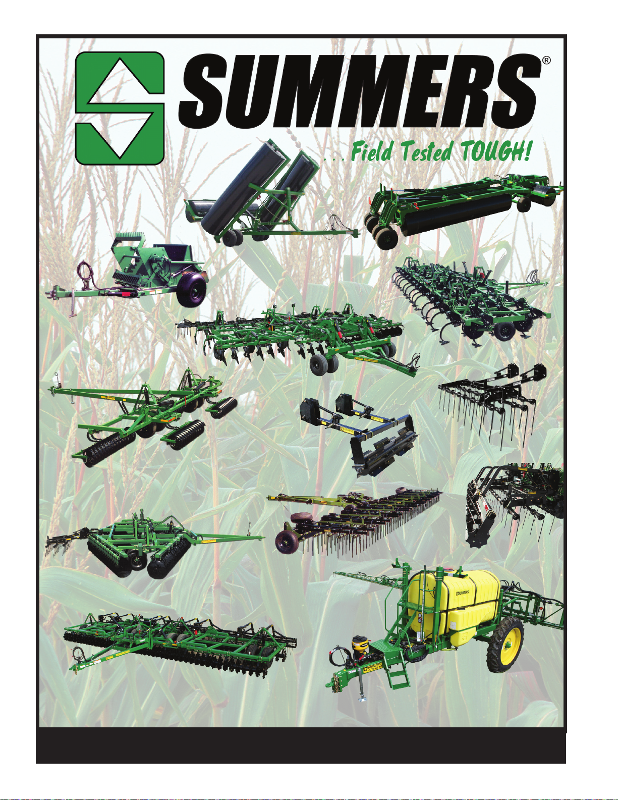
Model 700
Rock Picker
Hydraulic Fold
Coil Packer &
Hydraulic Fold
Rolling Chopper
Superrollers
Superchisel
Coulter-Chisel
Disk-Chisel
Mounted
Harrows
Rolling
Choppers
Superharrow Plus &
Superharrow 2650
Rolling
Diamond Disk &
Baskets
2510 DT
Supercoulter Plus
Ultra & Ultimate NT
Supersprayer
© Copyright 2013 Summers Manufacturing Co., Inc.
All Rights Reserved
11-1-12
To nd a dealer near you check out our website - www.summersmfg.com or call us at: 1 (800) 732-4347
SUMMERS Manufacturing Company, Inc. Maddock & Devils Lake, ND
 Loading...