

Summers 53 Trail-Type Superroller User Manual
41’, 46’ & 53’ SUPERROLLER
41’, 46’ & 53’
41’, 46’ & 53’ SUPERROLLER
SUPERROLLER
Operator’s
Manual
TRAIL-TYPE
IMPORTANT
THE OPERATOR IS RESPONSIBLE
FOR ADJUSTING THE MACHINE SINCE
MACHINE DOES NOT COME “FIELD
READY” FROM FACTORY.
See www.summersmfg.com for latest version of all Summers Operator’s Manuals.
SUMMERS MANUFACTURING CO., INC.
WEB SITE: www.summersmfg.com
MADDOCK, NORTH DAKOTA 58348 ................................... (701) 438-2855
DEVILS LAKE, NORTH DAKOTA 58301 ............................... (701) 662-5391
8Z1082 © Summers Mfg. Co., Inc. 2013 Printed in USA
READ & UNDERSTAND OPERATOR’S
MANUAL BEFORE USING MACHINE.
CAUTION

Warranty
Summers warrants only products of its manufacture against operational failure caused by defective materials
or workmanship which occur during normal use within 12 months from the date of purchase by the end user from
Summers’ dealer.
Summers’ obligation is to replace free of charge any part of any product that Summers inspection shows to be
defective excluding transportation charges to Maddock, ND or Devils Lake, ND and return and also excluding all
transportation costs from Summers’ dealer to the dealer’s customer and all other costs such as removal and installation expense.
Summers shall not be liable for loss of time, manufacturing costs, labor, material, loss of prots, consequential
damages, direct or indirect, because of defective products whether due to rights arising under the contract of sale or
independently thereof, and whether or not such claim is based on contract, tort or warranty.
Written permission for any warranty claim return must be rst obtained from authorized Summers’ personnel.
All returns must be accompanied with a complete written explanation of claimed defects and the circumstances of
operational failure.
Written warranty for all component parts used in the manufacture of Summers products is available upon request.
Warranty of such component parts will be determined by said component manufacturer upon their inspection of the
claimed defective part.
This express warranty is the sole warranty of Summers. There are no warranties, which extend beyond the warranty herein expressly set forth. The sales for products of Summers under any other warranty or guarantee express
or implied is not authorized. This warranty voids all previous issues.
SUMMERS MANUFACTURING CO. INC.
MADDOCK, NORTH DAKOTA 58348
DEVILS LAKE, NORTH DAKOTA 58301
2/95
3/2013

INTRODUCTION
This manual provides the following information about your Summers Land Roller.
SECTION CONTENTS
Section 1 – SAFETY explains important safety precautions and familiarizes the Operator with the decals and their
locations.
Section 2 – ASSEMBLY includes step by step assembly instructions for your Summers Land Roller.
Section 3 – LAND ROLLER OPERATION provides necessary information for the operation and adjustment of
the machine.
Section 4 – MAINTENANCE covers recommended mechanical maintenance. TROUBLESHOOTING provides a
quick reference to solving problems. SPECIFICATIONS lists important dimensions, capacities and
other technical information.
Section 5 – PARTS
OTHER ITEMS OF IMPORTANCE
A. Summers Mfg. Co., Inc. strongly recommends that each Land Roller Operator READ and UNDERSTAND the
Operator’s Manual before using the machine. In addition, this Operator’s Manual should be REVIEWED at
least ANNUALLY thereafter.
B. It is the policy of this company in improve its products whenever possible and practical to do so. We reserve
the right to make changes or improvements in the design or construction of parts at any time without incurring obligations to install such changes on products previously delivered.
C. Reference to “right” and “left” in this manual is determined when machine is viewed from the rear.
D. Parts are referenced in each drawing with the Summers Manufacturing Part Number. Use this Part Number
when ordering replacement parts from your Summers dealer. See back section of manual for description of
each Part Number.
E. WARNING – DO NOT ATTEMPT to raise machine into transport position if mud has built up on rollers or if
machine weight has been increased by any other means. Mechanical failure may occur.
F. Ability to safely operate the Summers Superroller is determined by both tractor horsepower and weight. The
minimum tractor weight for operating this implement is 20,000 lb. Minimum tractor engine horsepower is
180. Dual tires or single tires set at maximum width are required for safe operation of Land Roller.
G. Never tow this implement with less than an 20,000 lb. vehicle. Tongue weight in transport and eld positions
is 1150 lbs.
H. NEVER ALLOW anyone to work under Land Roller.
OWNER REGISTER
Name ____________________________________ Size _________________________________________
Address _________________________________ Serial Number _______________________________
City _____________________________________
(located by the hitch piece)
State/Prov. ______________________________ Date Purchased ______________________________
Mail Code ________________________________ Dealer _______________________________________
i

TABLE OF CONTENTS
SECTION 1 – SAFETY
Safety-Alert Symbol ......................................................................................................................1-1
General Safety Practices ..............................................................................................................1-1
Safety During Transport................................................................................................................1-2
Safety Decals ...............................................................................................................................1-2
Decals and Their Locations ................................................................................................... 1-2-1-6
SECTION 2 – ASSEMBLY
General Assembly Safety Instructions ..........................................................................................2-1
Safety Alert Symbol ......................................................................................................................2-1
General Safety Practices ..............................................................................................................2-2
Set-Up of Frame ............................................................................................................... 2-3 – 2-12
Hydraulic Set-Up ........................................................................................................................2-13
Wiring & Safety Light Installation ................................................................................................2-14
SECTION 3 – LAND ROLLER OPERATION
Land Roller Operation Safety .......................................................................................................3-1
Steps Prior to Operation ...............................................................................................................3-1
Initial Hookup ................................................................................................................................3-2
Steps Required to Unfold from Transport to Field Position ..........................................................3-3
Field Operation .............................................................................................................................3-4
Steps Required to Fold from Field to Transport Position ..............................................................3-4
Transporting .................................................................................................................................3-5
Unhooking Land Roller From Tractor ...........................................................................................3-6
SECTION 4 – MAINTENANCE
Maintenance Safety ......................................................................................................................4-1
Maintenance for after the First Day Four Hours of Operation ......................................................4-1
Daily and Periodic Maintenance ...................................................................................................4-1
Storage & Specications ..............................................................................................................4-2
SECTION 5 – PARTS
Center Frame ...............................................................................................................................5-2
Hitch .............................................................................................................................................5-3
Center Transport...........................................................................................................................5-4
Wing .............................................................................................................................................5-5
Wing Transport .............................................................................................................................5-6
Decal Locations ............................................................................................................................5-7
Hub and Axle Components ...........................................................................................................5-8
Hydraulics .....................................................................................................................................5-9
Safety Lights ...............................................................................................................................5-10
Acre Meter Option ......................................................................................................................5-11
Part Numbers ................................................................................................................. 5-12 – 5-16
ii
SECTION 1 - SAFETY
SAFETY-ALERT SYMBOL
This symbol is used to denote possible danger and
care should be taken to prevent bodily injury.
This symbol means:
ATTENTION! BECOME ALERT!
YOUR SAFETY IS INVOLVED!
Denition of each Signal Word used in conjunction with the Safety-Alert symbol.
indicates an imminently hazardous situation which, if not avoided, will result in death
DANGER
or serious injury. This signal word is to limited to the most extreme situations.
indicates a potentially hazardous situation which, if not avoided, could result in death
WARNING
CAUTION
1. READ AND UNDERSTAND Operator’s Manual before using machine. Review at least annually thereafter.
2. VERIFY all safety devices and shields are in place before using machine.
3. KEEP hands, feet, hair and clothing away from moving parts.
4. STOP engine, place all controls in neutral, set parking brake, remove ignition key and wait for all
moving parts to stop before servicing, adjusting, maintaining or unplugging.
5. BE CAREFUL when working around high pressure hydraulic system.
6. ALWAYS make sure Land Roller is lowered into eld position (cylinders retracted), it is blocked to prevent
movement and that pressure is relieved from hydraulic circuits before servicing.
7. DO NOT ALLOW RIDERS.
or serious injury.
indicates a potentially hazardous situation which, if not avoided, may result in minor
or moderate injury. It may also be used to alert against unsafe practices.
GENERAL SAFETY PRACTICES
8. USE EXTREME CARE when making adjustments.
9. KEEP CHILDREN AWAY from machinery at all times.
10. NEVER ALLOW anyone to work under Land Roller.
11. WARNING – DO NOT ATTEMPT to raise machine into transport position if mud has built up on rollers or if
machine weight has been increased by any other means. Mechanical failure may occur.
1-1
SAFETY DURING TRANSPORT
1. Ability to safely operate the Summers Superroller is determined by both tractor horsepower
and weight. The minimum tractor weight for operating this implement is 20,000 lbs. Minimum tractor engine horsepower is 180. Dual tires or single tires set at maximum width are
required for safe operation of Land Roller.
2. ONLY TOW at a safe speed – 20 MPH MAXIMUM. Use caution when making corners and
meeting trafc.
3. USE Safety Lights and Safety Chain between tractor drawbar and implement hitch when
transporting on public roads.
4. ALWAYS install lift cylinder locks before transporting on public roads.
5. FOLLOW ALL local laws governing transporting of farm machinery.
6. Use additional caution and reduce speed when towing under adverse conditions, when
turning and when on unlevel surfaces.
7. Frequently check for trafc from rear, especially during turns.
SECTION 1 - SAFETY
SAFETY DECALS
1. KEEP SAFETY DECALS CLEAN.
2. REPLACE missing or unreadable decals. New decals are available from your Summers
dealer by ordering correct part number (PN) located on the decal.
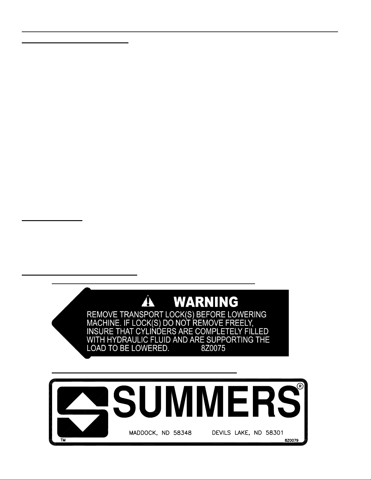
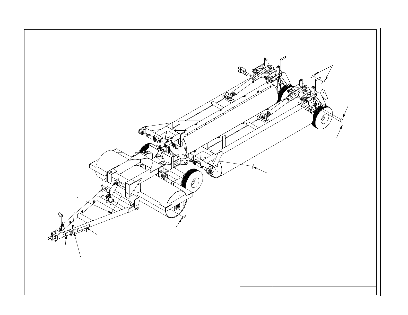
DECALS AND THEIR LOCATIONS
1. PN 8Z0075 – DECAL FOR REMOVING TRANSPORT LOCKS
2. PN 8Z0079 – DECAL FOR COMPANY IDENTIFICATION
1-2

SECTION 1 - SAFETY
3. PN 8Z0087 – DECAL FOR PINCH POINT HAZARD
4. PN 8Z0132 – SUPERROLLER ID DECAL
5. PN 8Z0276 – DECAL FOR GENERAL CAUTION
1-3

SECTION 1 - SAFETY
6. PN 8Z0800 – AMBER REFLECTOR
7. PN 8Z0805 – RED-ORANGE REFLECTOR
8. PN 8Z0810 – RED REFLECTOR
SAFETY LIGHT OPERATION
The Summers Safety Light Kit is equipped with a 7 pin connector which meets SAE J560 specication. To protect 7
pin connector, store in dust cap (8K8067) when not attached to towing vehicle.
On most towing vehicles WITHOUT brake lights:
Amber lights will turn on with ashers or turn signals.
Red lights will turn on with parking, road or eld lights.
On most towing vehicles WITH brake lights:
Amber lights will turn on with ashers, turn signals OR when brake is applied.
Red lights will turn on with parking or road lights.
1-4
1-5
8Z0805
8Z0087
SECTION 1 - SAFETY
8Z0800
8Z0800
8Z0075
8Z0087
8Z0276
8Z0079
8Z0132
8Z0800
WARNING STICKERS ARE THE SAME ON
THE RIGHT SIDE OF MACHINE.
DECALS2/27/2013 9LR0410.iam/

SECTION 1 - SAFETY
1-6

SECTION 2 - ASSEMBLY
GENERAL ASSEMBLY SAFETY PRACTICES
1. READ AND UNDERSTAND Operator’s Manual before assembly of machine.
2. If machine is to be assembled INDOORS, check that exit door is a MINIMUM OF 14’
WIDE and a MINIMUM of tractor height.
3. Reference to “RIGHT” and “LEFT” is determined when machine IS VIEWED FROM
THE REAR.
4. Reference to “FORWARD” means TOWARDS THE TRACTOR.
5. Reference to “REAR” means AWAY FROM THE TRACTOR.
SAFETY-ALERT SYMBOL
This symbol is an alert to the potential
for personal injury. This symbol means
ATTENTION! BECOME ALERT!
YOUR PERSONAL SAFETY IS INVOLVED!
2-1
SECTION 2 - ASSEMBLY
GENERAL SAFETY PRACTICES
YOU ARE RESPONSIBLE for the
safe assembly of the machine.
DO NOT ALLOW CHILDREN or
other unauthorized persons within
the assembly area.
WEAR PERSONAL PROTECTIVE
EQUIPMENT which includes a
hard hat, eye protection, work
gloves and steel toed boots with
slip resistant soles.
DO NOT MODIFY the equipment
or substitute parts in any way.
Unauthorized modification may
impair the function and/or safety
of the machine.
USE SUITABLE LIFTING
DEVICE for components which
could cause personal injury.
BLOCK UP ANY RAISED PART of
the machine. Be sure machine is
stable after blocking.
ALWAYS INSPECT LIFTING
CHAINS AND SLINGS for damage
or wear.
BE SURE LIFTING DEVICE
IS RATED TO HANDLE THE
WEIGHT.*
STOP ENGINE, place all controls
in neutral, set parking brake,
remove ignition key and wait for
all moving parts to stop before
servicing or adjusting.
ALWAYS make sure Land Roller
is lowered into field position
(cylinders retracted), it is blocked
to prevent movement and that
pressure is relieved from hydraulic
circuits before servicing.
2-2
USE EXTREME CARE when
assembling, servicing or adjusting.
SECTION 2 - ASSEMBLY
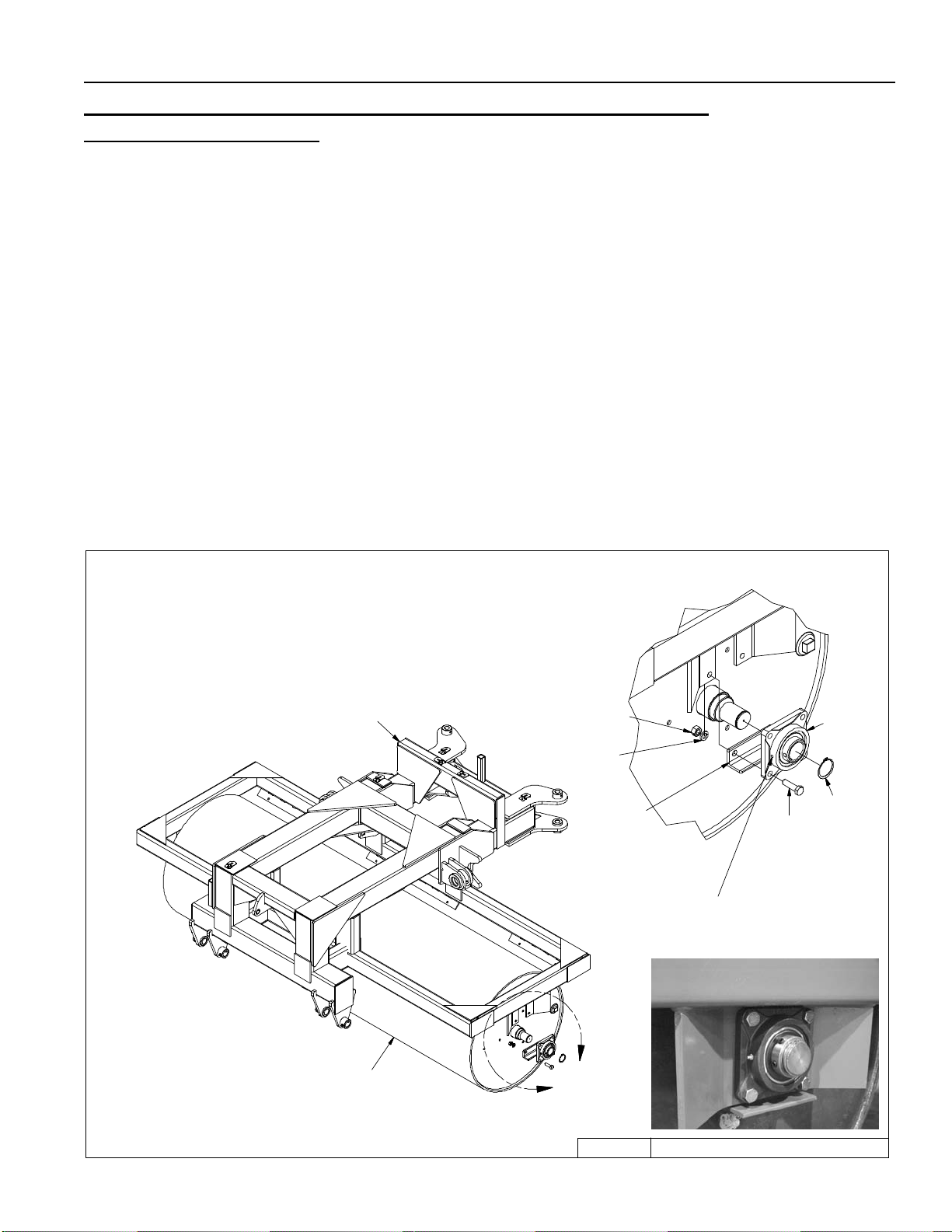
Main Frame Roller Installation (Instructions for 41’, 46’ & 53’)
(NOTE: 41’ shown in drawings)
MF1. Position 8P4211 on a at even surface; block the roller to avoid unexpected movement. CAU-
TION: The 11’ roller weighs 3300 lbs., use extreme care when moving rollers and frame com-
ponents. NOTE: An H has been stamped onto one end of each roller. Position the center roller
with the H to the left. All other rollers should have the H positioned to the center of the machine.
MF2. Use a fork lift or crane to position the main frame 8P7122 over the center drum and lower the
frame so the roller axle stubs t between the bearing hangers as shown in the Figure 1.
MF3. Install bearings with the grease zerk toward the rear of the machine. Secure to bolt plates
with the hardware shown. Install reinforcement angles between the bottom attachment hole
on the inside of the bolt plate, as shown in Figure 1.
MF4. Install snap rings on each roller shaft. Ensure that the roller is centered in the bearings and
tighten the set screws.
MF5. Before removing the lifting device for the main frame, block the frame in the locations shown
in Figure 1, also install blocks under the roller to keep it from rolling.
Figure 1
SNAP RING IS OPTIONAL.
DUE TO MANUFACTURING TOLERANCE THE SNAP RING MAY NOT BE NEEDED.
8P7122
↑
↑
BLOCK FRAME
AT ARROWS
8X0265
3/4" LN
8X0306
3/4" LW
8P5080
NOTE ORIENTATION
OF GREASE ZERK
DETAIL A
SCALE 1 / 10
8X0111
3/4" X 2-1/2"
8R8010
8R8005
SNAP RING
AFTER DRUM IS INSTALLED
PLACE STANDS AT THE 4
LOCATIONS SHOWN TO
STABILIZE FRAME
8P4211
↑
↑
A
CENTER3/8/2012 9LR0410.iam/
2-3

SECTION 2 - ASSEMBLY
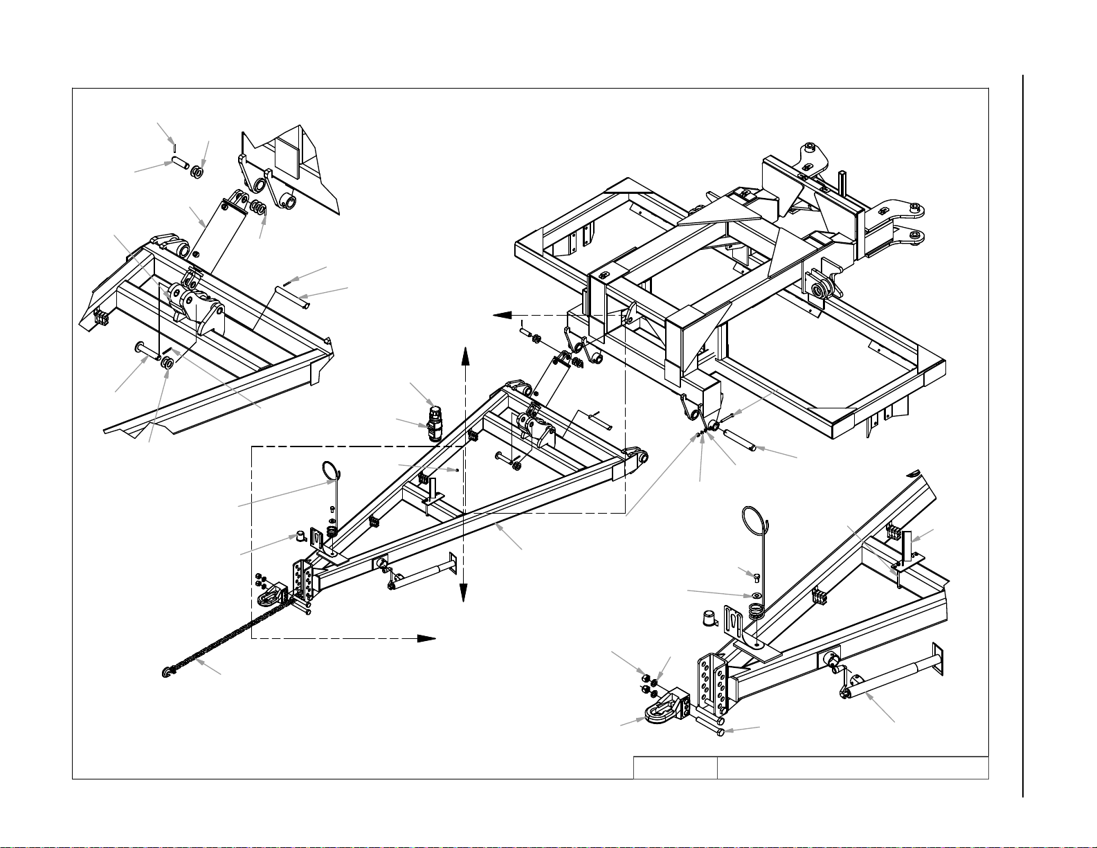
Hitch Installation
H1. Position hitch as shown in Figure 2; install the pins and hardware shown in Figure 2.
IMPORTANT
Always install the pins with the cross hole towards the outside. Pay attention to the orientation of the cross hole in the pin to the cross hole in the bushing on the main frame, only
drive the pin in far enough to line up the holes, install the fasteners shown in Figure 2.
H2. Install the jack stand and pin.
H3. Install the hitch clevis and hardware shown on the front of the hitch.
H4. Install the Pivot lock and cylinder at the rear of the front hitch. Install the pins and washers as
shown. Note the orientation of the pivot lock, do not install it backwards.
2-4
1/4 X 2" RP
8K9106
8P7140
8D9108
1 1/4" FW
8P0510
8X0327
1/4 X 2" RP
8D9108
Figure 2
8D9108
1/4 X 2" RP
8D1236
8K1620
2-5
DETAIL A
8X0327
1 1/4" FW
NOTE:
DRUM OMITTED FROM THIS VIEW
SCALE 1/20
8D8500
8K8067
ROLL PIN
8D2470
8X0523
8Z1000
8A1004
5" HC
8X0203
3/8" FN
A
B
8X0253
NY-LOCK 5/8"-11NC
8P7137
8X0281
NY-LOCK 1"
8D0720
8X0318
3/4" FW
8X0309
1" LW
8X0304
5/8" LW
8X0110
3/4 X 1-1/4"
8X0323
5/8" FW
8X0095
5/8" X 5"
8P3910
8A1157
3/8 X 4-1/16 X 7"
8X0140
1 X 7"
9LR0410.iam/
SECTION 2 - ASSEMBLY
8T4385
DETAIL B
SCALE 1/20
8D8522
HITCH5/8/2014
 Loading...