

Summers 3-Rank Superweeder User Manual
®
SUMMERS
Operator’s
Manual
CULTI-HARROW
SUPERHARROW
3-RANK
SUPERWEEDER
IMPORTANT
THE OPERATOR IS RESPONSIBLE
FOR ADJUSTING THE MACHINE SINCE
MACHINE DOES NOT COME “FIELD
READY” FROM F ACTORY.
SUMMERS MANUFACTURING CO., INC.
WEB SITE: www.summersmfg.com
MADDOCK, NORTH DAKOTA 58348 .................................. (701) 438-2855
DEVILS LAKE, NORTH DAKOTA 58301 ............................. (701) 662-5391
HDC
CAUTION
READ & UNDERSTAND OPERATOR’S
MANUAL BEFORE USING MACHINE.
8Z 110 0 © Summers Mfg. Co., Inc. 2004 Printed in USA

Warranty
Summers warrants only products of its manufacture against operational failure caused by defective materials or
workmanship which occur during normal use within 12 months from the date of purchase by the end user from
Summers’ dealer .
Summers’ obligation is to replace free of charge any part of any product that Summers inspection shows to be
defective excluding transportation charges to Maddock, ND or Devils Lake, ND and return and also excluding all
transportation costs from Summers’ dealer to the dealer’s customer and all other costs such as removal and inst allation expense.
Summers shall not be liable for loss of time, manufacturing costs, labor, material, loss of profits, consequential
damages, direct or indirect, because of defective products whether due to rights arising under the contract of sale or
independently thereof, and whether or not such claim is based on contract, tort or warranty .
Written permission for any warranty claim return must be first obtained from authorized Summers’ personnel. All
returns must be accompanied with a complete written explanation of claimed defects and the circumstances of operational failure.
Written warranty for all component parts used in the manufacture of Summers products is available upon request.
Warranty of such component parts will be determined by said component manufacturer upon their inspection of the
claimed defective part.
This express warranty is the sole warranty of Summers. There are no warranties, which extend beyond the
warranty herein expressly set forth. The sales for products of Summers under any other warranty or guarantee
express or implied is not authorized. This warranty voids all previous issues.
SUMMERS MANUFACTURING CO. INC.
MADDOCK, NORTH DAKOT A 58348
DEVILS LAKE, NORTH DAKOT A 58301
2/95

INTRODUCTION
This manual provides information about Safety, Assembly, Operation and Parts for the Summers Culti-Harrow,
Superharrow and 3-Rank Superweeder featuring the Summers 16 and 20 Ft. Hitch.
Please refer to these sections before assembling or operating your machine.
Reference to “right” and “left” in this book is determined when the machine is viewed from the rear .
It is the policy of the company to improve its products whenever possible and practical to do so. We reserve the right to
make changes or improvements in the design or construction of parts any time without incurring obligations to install such
changes on products previously delivered.
Summers Mfg. Co., Inc. strongly recommends that each Operator READ and UNDERSTAND the Operator’s Manual
before using the machine. In addition, this Operator’s Manual should be reviewed at least ANNUALL Y thereafter .
Parts are referenced in each drawing with the Summers Manufacturing Part Number . Use this Part Number when ordering
replacement parts from your Summers dealer . See back section of manual for description of each Part Number.
SECTION CONTENTS
Section 1: SAFETY: ALL MACHINES
Section 2: AS S E M B LY : C U LTI-HARROW
Section 3: ASSEMBL Y: SUPERHARROW
Section 4: AS S E M B L Y: 3-RANK SUPERWEEDER
Section 5: 16 Ft. HITCH AUTO FOLD
Section 6: 20 Ft. HITCH AUTO FOLD
Section 7: OPERA TION – ALL MACHINES
Section 8: P A R T S – A LL MACHINES
Section 9: P A R T NUMBERS and DESCRIPTIONS
OWNER REGISTER
Name_____________________________________ Size __________________________________________
Address __________________________________ Serial Number _________________________________
City______________________________________
(located on frame)
State/Prov . ________________________________ Date Purchased ________________________________
Mail Code_________________________________ Dealer________________________________________
i

TABLE OF CONTENTS
SECTION 1: SAFETY: ALL MACHINES
Safety-Alert Symbol & General Safety Practices..................................................................................... 1-1, 1-2
Safety Decals & Reflectors ........................................................................................................................1-3 - 1-7
General Assembly Safety Practices....................................................................................................................1-8
SECTION 2: ASSEMBLY: CUL TI-HARROW
Set-Up Instructions ...................................................................................................................................2-1 - 2-6
SECTION 3: ASSEMBLY: SUPERHARROW
Set-Up Instructions ...................................................................................................................................3-1 - 3-8
SECTION 4: ASSEMBLY: SUPERWEEDER
Set-Up Instructions ................................................................................................................................. 4-1 - 4-14
SECTION 5: 16 FT . AUTO FOLD
Set-Up Instructions ...................................................................................................................................5-1 - 5-4
SECTION 6: 20 FT . AUTO FOLD
Set-Up Instructions ...................................................................................................................................6-1 - 6-2
SECTION 7: OPERA TION
Transport To Field .............................................................................................................................................7-1
Unhitching Machine..........................................................................................................................................7-1
Culti-Harrow Adjustments ..........................................................................................................................7-1, 7-2
Superharrow Adjustments .................................................................................................................................7-2
Superweeder Adjustments.......................................................................................................................... 7-2, 7-3
Transport & Storage: All Auto-Fold Machines .................................................................................................7-3
Maintenance & Service .....................................................................................................................................7-4
Troubleshooting................................................................................................................................................7-4
SECTION 8: PARTS
Hitch Assembly - 16 Ft.......................................................................................................................................8-2
Auto-Fold Assembly - 16 Ft. .............................................................................................................................8-3
Hydraulic System - 16 Ft. ...................................................................................................................................8-4
Drawbar - 16 Ft...................................................................................................................................................8-5
Hitch Assembly - 20 Ft.......................................................................................................................................8-6
Auto-Fold Assembly - 20 Ft. .............................................................................................................................8-7
Hydraulic System - 20 Ft. ...................................................................................................................................8-8
Drawbar - 20 Ft...................................................................................................................................................8-9
Drawbar Centers and Wings.................................................................................................................. 8-10 - 8-11
Transport Axle .................................................................................................................................................8-12
Cables and Pins ...............................................................................................................................................8-13
Superweeder Sections - 3 Rank........................................................................................................................8-14
Superweeder Hydraulic System ............................................................................................................. 8-15 - 8-16
5-1/2 Ft. Harrow Section - 5 Bar .......................................................................................................................8-17
7 Ft. Harrow Section - 5 Bar .............................................................................................................................8-18
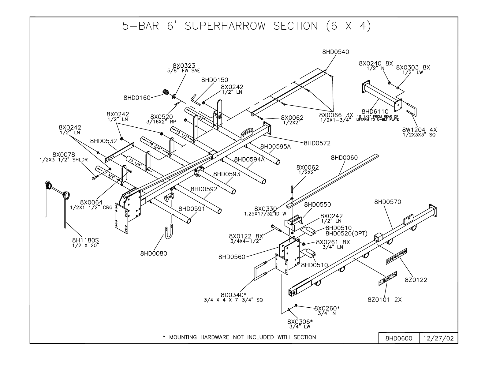
6 Ft. Superharrow Section - 5 Bar..................................................................................................................... 8-19
Light Kit........................................................................................................................................................... 8-20
Hub and Axle Components.............................................................................................................................. 8-21
SECTION 9: PART DESCRIPTIONS
Part Numbers and Descriptions ............................................................................................................... 9- 1 - 9-14
ii
SECTION 1 - SAFETY
SAFETY-ALERT SYMBOL
This symbol is used to denote possible danger
And care should be taken to prevent bodily
Injury . This symbol means:
A TTENTION! BECOME ALERT!
YOUR SAFETY IS INVOL VED!
Definition of each Signal Word used in conjunction with the Safety-Alert symbol.
indicates an imminently hazardous situation which, if not avoided, will result in death or
serious injury . This signal word is to be limited to the most extreme situations.
DANGER
indicates a potentially hazardous situation which, if not avoided, could result in death or
serious injury .
WARNING
indicates a potentially hazardous situation which, if not avoided, may result in minor or
moderate injury. It may also be used to alert against unsafe practices.
CAUTION
GENERAL SAFETY PRACTICES
1. READ AND UNDERSTAND Operator’s Manual before using machine. Review at least annually
thereafter.
2. VERIFY all safety devices and shields are in place before using machine.
3. KEEP hands, feet, hair and clothing away from moving parts.
4. STOP engine, place all controls in neutral, set parking brake, remove ignition key and wait for all
moving parts to stop before servicing, adjusting, maintaining or unplugging.
5. BE CAREFUL when working around high pressure hydraulic system.
6. ALWAYS make sure that pressure is relieved from hydraulic circuits before servicing.
7. DO NOT ALLOW RIDERS.
8. USE EXTREME CARE when adjustments.
9. KEEP CHILDREN AWAY from machinery at all times.
10. NEVER ALLOW anyone to walk or work under a raised piece of equipment without installing transport
locks.
1-1
SECTION 1 - SAFETY
SAFETY DURING TRANSPORT
1. ONLY TOW at a safe speed. Use caution when making corners or meeting traffic.
2. USE a safety chain between tractor drawbar and implement hitch when transporting on public roads.
3. AL WAYS use transport locks when transporting on public roads.
4. COMPL Y with local lighting, marking and maximum wid th regulations when transporting on highways.
WARNING
IMPORTANT INFORMATION ON 16 & 20 FT. HITCH MACHINES
WITH NEGATIVE HITCH WEIGHT
Because of the large wing size of certain Summers
Culti-Harrows and because of the added weight on
all Summers Superweeders and Superharrows, the
hitch on these machines often becomes “light” in
transport position. This means that there is no downward weight on the hitch and as a result, the hitch
will rise if unhitched. In these cases, special precautions must be taken as discussed below. This condition can exist even if the hitch is equipped with a spray
or granular attachment.
NEVER unhitch a machine that has been opened up
into field position and has not been completely lowered to the ground. If the machine has been completely lowered to the ground and parked in a level
area, it may be unhitched with ordinary care. NEVER
unhitch a machine in transport position from a tractor, pickup, truck or other towing unit unless the following precautions are taken.
1. Determine if the hitch has a positive or negative weight.
Insure that there is no side pressure on the hitch pin before determining positive or negative tongue weight. If
the Culti-Harrow, Superweeder and Superharrow’ s hitch
piece or clevis is resting on the towing unit’s hitch and
cannot be lifted off, positive tongue weight exists. The
machine can be unhitched by lowering the hitch jack, stabilizing with one wing tube jack and following steps 2 and
4. If positive tongue weight does not exist, follow steps
2 through 4.
2. Park the machine on a level area and block the hitch
tires and wing transport tires so the machine cannot roll
forward or backward. This is very important even if the
machine is parked on level ground, strong winds often
move unblocked machines.
3. Lower the wing tube jacks until enough weight is
transferred to the hitch to keep it from rising. Check
this by observing the machine hitch. With the hitch pin
installed but not binding with the machine hitch, check
that the machine hitch no longer has a tendency to rise.
4. Disconnect all hydraulic lines. Again check that the
hitch pin is free. There should be no side force on the
pin and it should turn freely . If free, st and of f to the left
side of the hitch and remove the hitch pin. Carefully
drive ahead.
IMPORT ANT : The positioning of the transport wheel
assemblies on the wing tubes of the machine is very
critical in determining hitch weight. Moving transport wheel assemblies forward will increase hitch
weight and moving them rearward will decrease
hitch weight.
1-2
SECTION 1 - SAFETY
SAFETY DECALS
1. KEEP SAFETY DECALS AND REFLECT ORS CLEAN.
2. REPLACE missing or unreadable decals. New decals are available from your Summers dealer by
stating correct part number (PN) located in lower right hand corner .
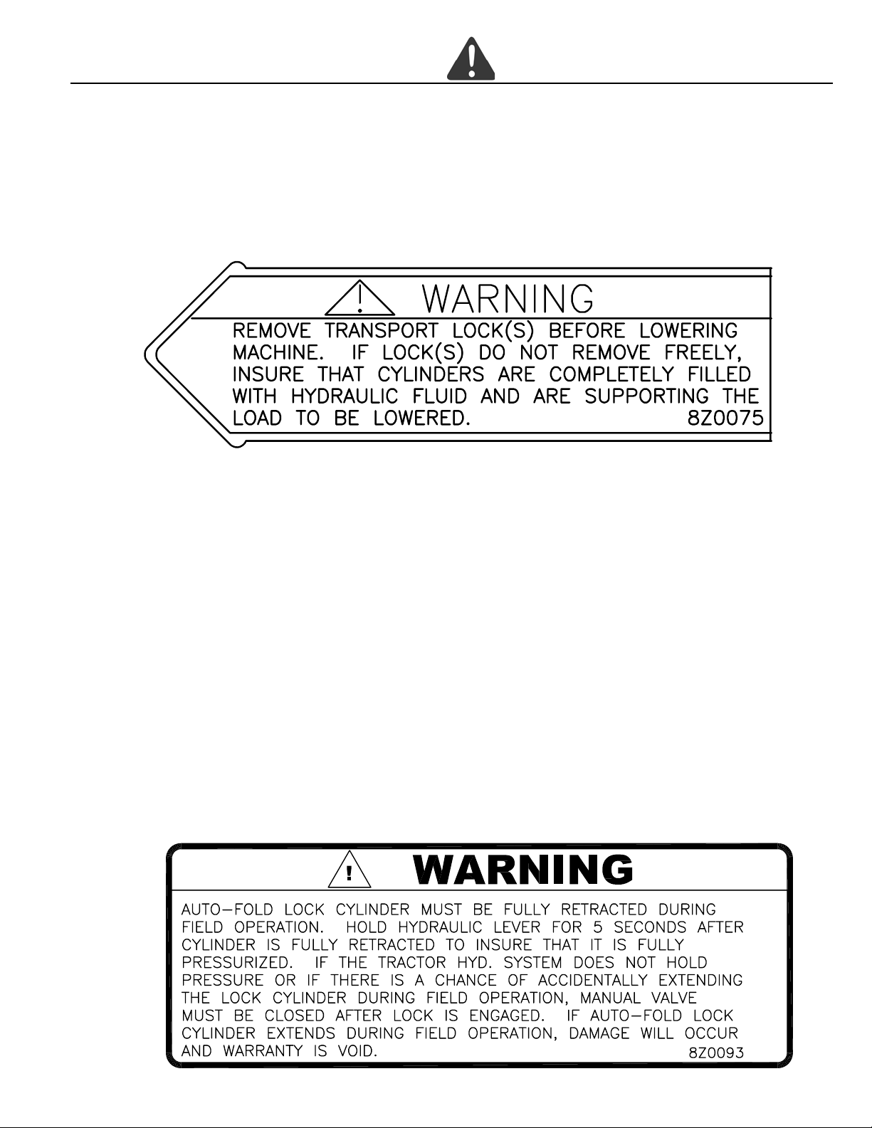
1. TRANSPORT LOCK DECAL (PN 8Z0075) – Used on all machines.
2. HITCH WARNING DECAL (PN 8Z0092)
3. AUTO-FOLD W ARNING DECAL (PN 8Z0093) - 20’ HITCH ONL Y
1-3
SECTION 1 - SAFETY
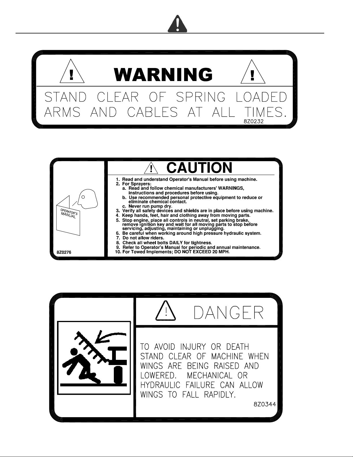
4. AUTO-FOLD ARM WARNING DECAL (PN 8Z0232)
5. GENERAL CAUTION DECAL (PN 8Z0276)
6. WING DANGER DECAL (PN 8Z0344)
1-4
SECTION 1 - SAFETY
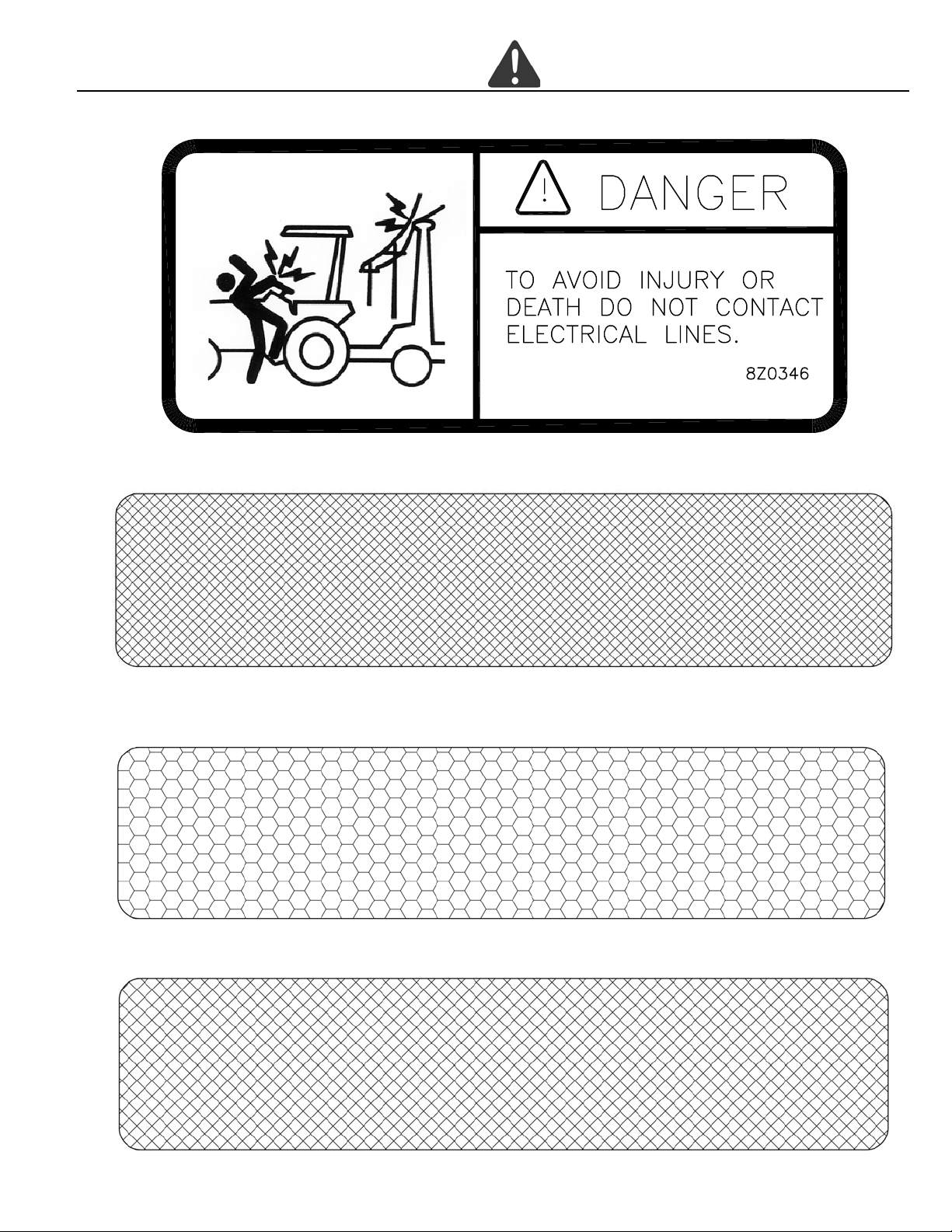
7. ELECTROCUTION DANGER DECAL (PN 8Z0346)
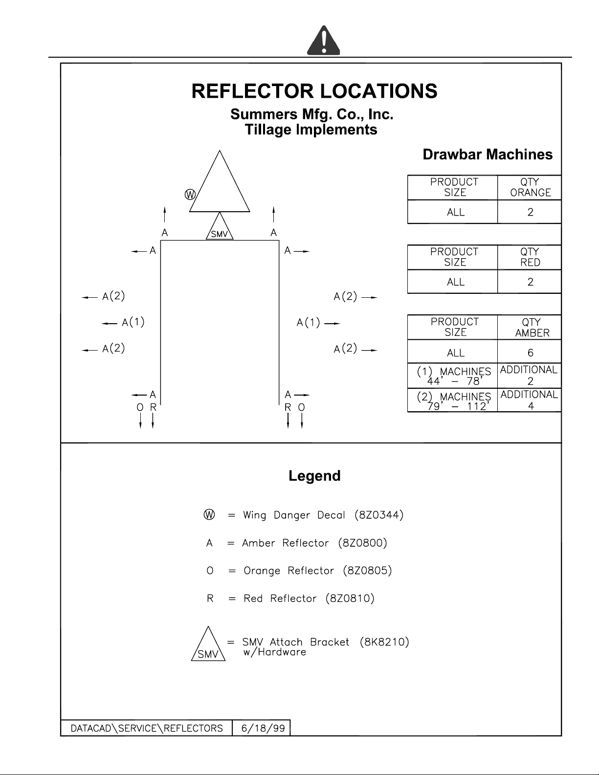
8. AMBER REFLECTOR (PN 8Z0800)
9. RED-ORANGE REFLECTOR (PN 8Z0805)
10. RED REFLECTOR (PN 8Z0810)
1-5
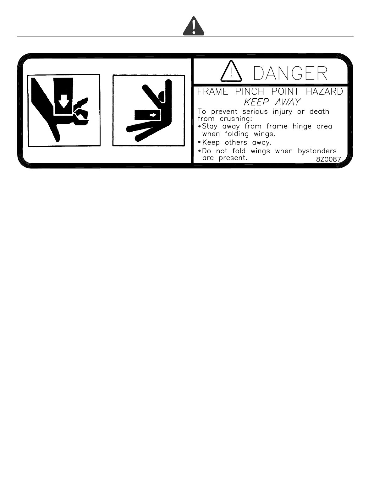
11. PINCH POINT DECAL (PN 8Z0087)
SECTION 1 - SAFETY
1-6
SECTION 1 - SAFETY
1-7
SECTION 1 - SAFETY
GENERAL ASSEMBL Y SAFETY PRACTICES
YOU ARE RESPONSIBLE for the safe assembly of the machine.
DO NOT ALLOW CHILDREN or other unauthorized persons within the assembly
area.
WEAR PERSONAL PROTECTIVE
EQUIPMENT which includes a hard hat,
eye protection, work gloves and steel toed
boots with slip resistant soles.
DO NOT MODIFY the equipment or substitute parts in any way . Unauthorized modification may impair the function and/or
safety of the machine.
USE SUITABLE LIFTING DEVICE for
components which could cause personal
injury.
BLOCK UP ANY RAISED P ART of the
machine. Be sure machine is stable
after blocking.
AL WA YS INSPECT LIFTING CHAINS
AND SLINGS for damage or wear.
BE SURE LIFTING DEVICE IS
RATED TO HANDLE THE WEIGHT.
STOP ENGINE, place all controls in
neutral, set parking brake, remove ignition key and wait for all moving parts
to stop before serving or adjusting.
BE SURE PRESSURE IS RELIEVED
from hydraulic circuits before servicing or disconnecting from tractor.
USE EXTREME CARE when servicing or adjusting.
GENERAL ASSEMBL Y INSTRUCTIONS
1. READ AND UNDERSTAND Operator’s Manual before assembly of machine.
2. Reference to “RIGHT” and “LEFT” is determined when machine IS VIEWED FROM THE REAR.
3. Reference to “FORWARD” means TOWARDS THE TRACTOR.
4. Reference to “REAR” means AWAY FROM THE TRACTOR.
1-8
SECTION 2 – SET-UP INSTRUCTIONS — CULTI-HARROW
Fig. 1
The machine should be placed in an area that allows ample room for assembly in field position (See Fig. 1).
CAUTION: For safety purposes, block equipment while working on it.
Refer to illustrations and parts listing on pages 8-2 through 8-20 and follow these steps when assembling.
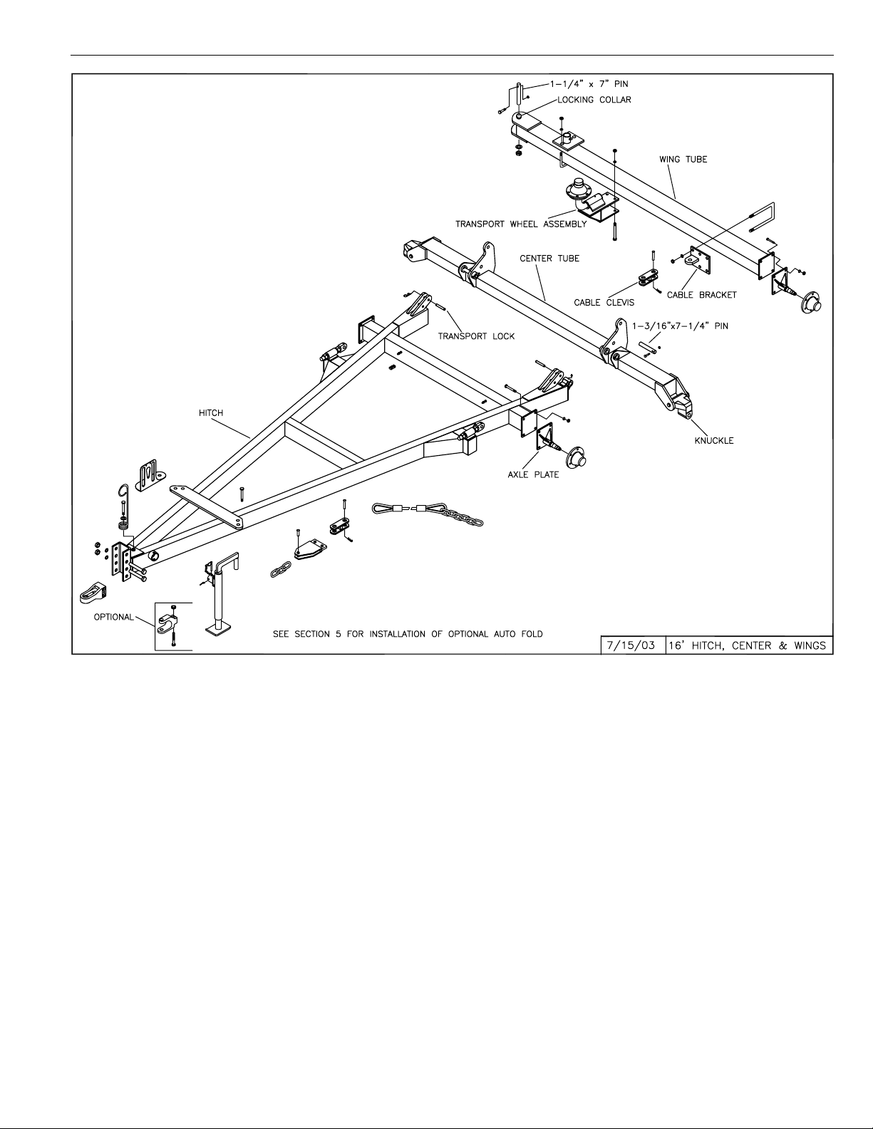
16’ HITCH ASSEMBLY
HITCH, HUBS AND WHEELS
Mount axle plates with spindles down for 1 1L tires and with spindles up for 14L tires. Mount hitch wheels and tires and install
hitch jack.
CENTER WING DRAWBAR TUBES FOR 16’ HITCH
Attach center tube to hitch using (2) 1-3/16” x 7-1/4” pins and secure with 7/16” x 3” bolts and locknuts. Attach wing tubes to
center tube knuckles using 1-1/4” x 7” pins. When in field position, the locking collar is on top. Insert a 7/16” x 3” bolts through
locking collar and hole in top of each pin, secure with locknut. Secure pin with 1” flat washer and 1” NC lock jam nut.
IMPORT ANT: Be sure to install wing tube spindles with spindle down when in field position.
Mount support wheels and tires. Do not mount transport wheel assemblies until lift arms are positioned.
2-1
SECTION 2 – SET-UP INSTRUCTIONS — CULTI-HARROW
Fig. 2
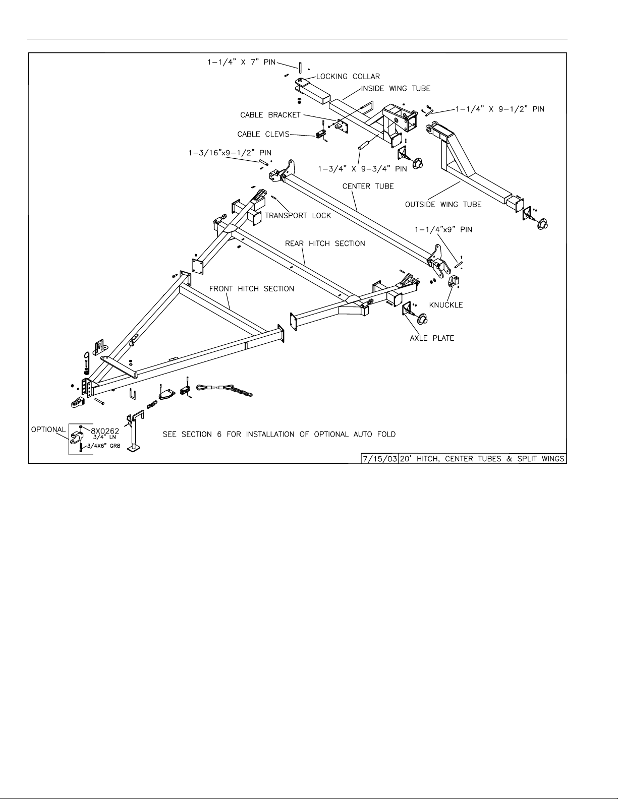
20’ HITCH ASSEMBL Y
Bolt the two A-frame sections of the hitch together, using eight 7/8” bolts and locknuts.
NOTE: Since these larger pieces have a tendency to warp when welded, it may be necessary to pull the legs of the hitch
together to match the center tube brackets.
HITCH, HUBS AND WHEELS
Mount axle plates with spindles down for 1 1L tires and with spindles up for 14L tires. Mount hitch wheels and tires and install
hitch jack.
CENTER WING DRAWBAR TUBES FOR 16’ HITCH
Attach center tube to hitch using (2) 1-3/16” x 9-1/2” pins. Secure with 7/16” x 3” bolts and locknuts. Att ach inside section of
hinged-wing with 1-1/4” x 7” pin and secure with 7/16” x 3” bolt and locknut. Secure pins with 1” flat washer and 1” NC lock jam
nut.
Attach outside wing and secure with 1-3/4” x 9-3/4” pin, 7/16” x 3-1/2” bolt and lock nut. Mount wing tube spindles with spindle
down in field position. Do not install transport wheel assemblies until lift arms are positioned.
2-2
SECTION 2 – SET-UP INSTRUCTIONS — CULTI-HARROW
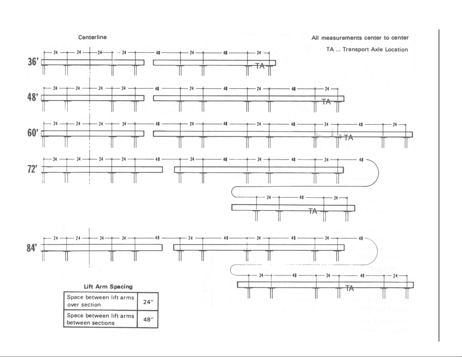
LIFT ARMS
Attach the lift arms to the wing tubes using 7/16” x 7-1/4” bolts.
Start at machine center and measure outward using the following
guide.
All measurements are to the center of the lift arms. The end lift
arm on each wing should be close to the end wheel so the section
harrows out the wheel track.
In cases where both 5-1/2’ and 7’ sections are used on the wings,
the 7’ sections are used on the ends.
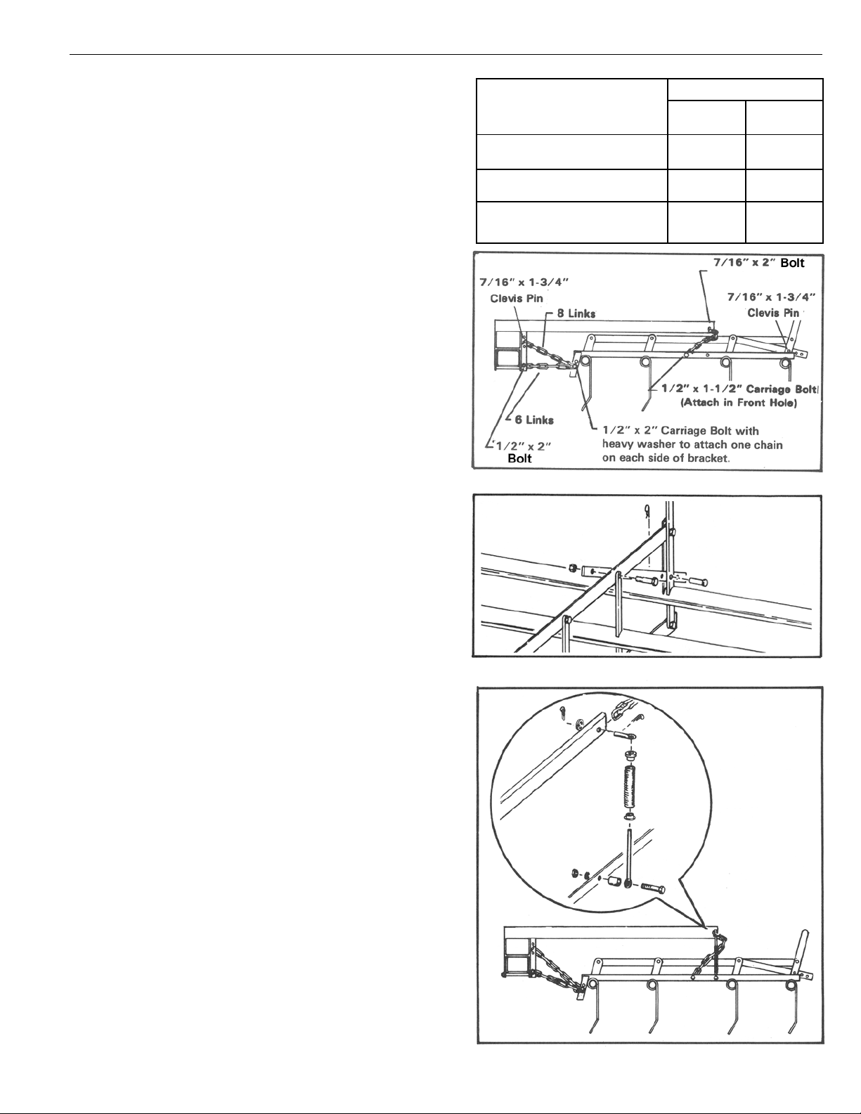
SECTIONS:
Assemble 5 bar section linkage as shown in figure 4.
The sections are attached as shown in figure 3. Connect the 8-
link pull chain to the middle hole of the lift arm using a clevis pin
and hair pin. Connect the 6-link pull chain to the bottom hole of
the lift arm using a 1/2” x 2” bolt, lockwasher and nut. Position
harrow section as shown and secure using a 1/2” x 2” carriage
bolt, flat washer and lock nut to attach one chain on each side of
bracket.
Sp ace from drawbar center
to first lift arm on either side
Sp ace between lift arms
over section
Sp ace between lift arms
of adjoining sections
SECTION SIZE
5-1/2’ 7’
5 BAR 5 BAR
16-1/4” 16-1/4”
32-1/2” 52”
32-1/2” 31”
Secure with heavy flatwasher and locknut. Repeat for other side
of section.
Attach the 9-link lift chain to the lift arm with a 7/16” x 2” bolt.
Attach the lift chain to the section with a 1/2” x 1-1/2” carriage bolt
inserted in the front hole.
OPTIONAL SPRING PRESSURE
To assemble the optional spring pressure to the lift arms, first insert an eye-bolt through the lift arm with the eye toward the outside
of the harrow section (See figure 5). Attach other end to the harrow
section with a 1/2” x 2-1/4” bolt, lock washer and nut. Install a
bushing between the eye-bolt and section as illustrated. Repeat
for the other side of the section.
TRANSPORT WHEELS
Install the transport wheel as shown in Fig. 1. Place the transport
wheel assembly over the end section on units up to 56 ft. On sizes
over 56 ft., install over the second section or between end sections. On the 84 ft. model, install wheel between the two end sections. On the 98 ft. model, install wheel over the second section
from the end. On the 112 f t. model, install wheel between the second and third sections from the end.
Secure with two 5/8” x 5-1/2” bolts, lock washers and nuts.
Fig. 3 Harrow Section Mounting
Fig. 4 5-Bar Section Linkage Assembly
NOTE: Transport wheel brackets are made for left and right
and are not interchangeable.
IMPORT ANT: The positioning of the transport wheel assemblies on the wing tubes of the machines is very critical in
determining hitch weight. Moving transport wheel assemblies forward will increase hitch weight and moving rearward will decrease hitch weight. See the “Warning Regarding Machines With Negative Hitch Weight” on page 1-2 for
2-3
Fig. 5 Spring Pressure Assembly
SECTION 2 – SET-UP INSTRUCTIONS — CULTI-HARROW
more information.
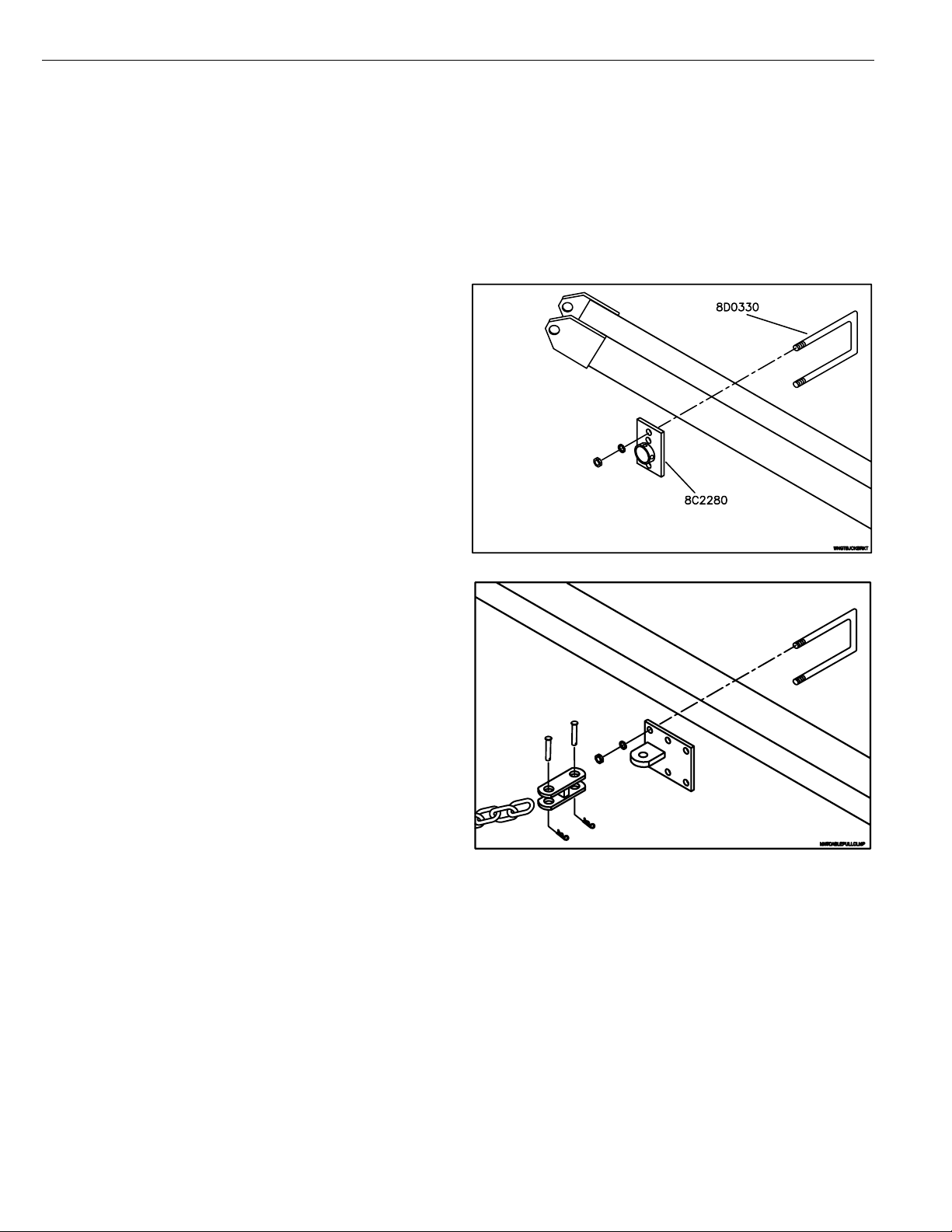
WING TUBE JACK BRACKET
Harrows without sprayers on hitch may require the transport wheel assemblies to be positioned further ahead to provide a
better balance on the hitch. A wing tube jack bracket is provided with all machines and allows for mounting the hitch jack on the
wing tube for added stability . (See Fig. 6).
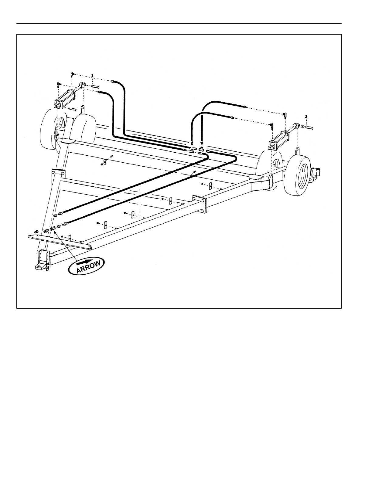
CABLES
Install cable brackets and cable assemblies as shown in figures 1, 2 and 7. Secure brackets using 3/4” U-bolts, lock washers
and nuts. T wo cables are required for each wing on the hinged wing models.
T o prevent outside cable from catching on transport tire on 1 12’
Culti-Harrows, install cable guides directly behind transport tire
as shown on page 8-10.
NOTE: Adjust cables so wings slightly lead center when
standing in field position.
IMPORTANT: On machines with two cables per wing, the
cables must be adjusted to have equal tension.
Fig. 6 Wing Tube Jack Bracket
Fig. 7 Mounting Cable Pull Clamps
2-4

SECTION 2 – SET-UP INSTRUCTIONS — CULTI-HARROW
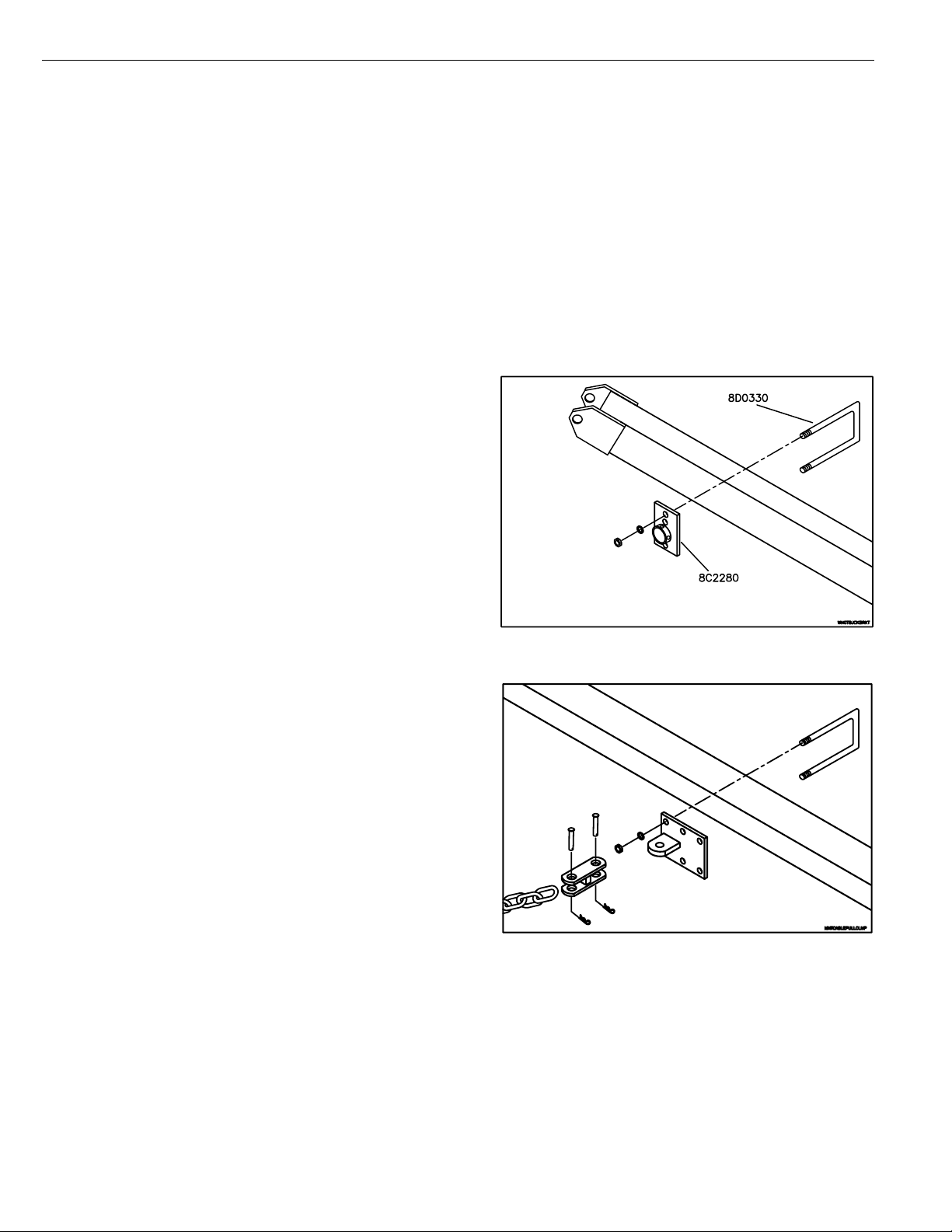
HYDRAULIC SYSTEMS FOR MACHINES WITH 16 OR 20 FT. HITCHES
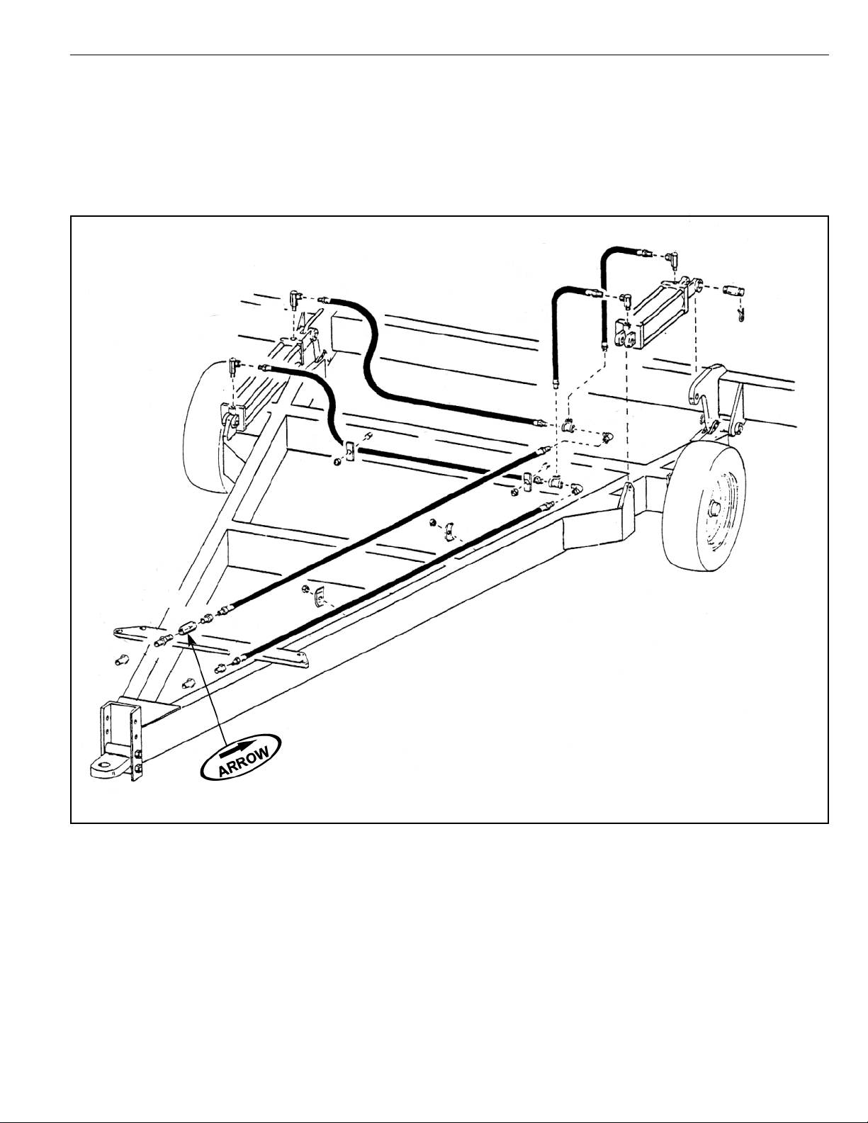
Mount lift cylinders and assemble hose lines as shown in
figures 19 and 20.
NOTE: The hydraulic line leading from the rod-end of
the lift cylinders requires a restrictor valve on the tractor end. Thread this valve on with the arrow pointing
back towards the cylinders as illustrated.
Fig. 19 Hydraulic Lift System - 16 ft. Hitch
2-5
SECTION 2 – SET-UP INSTRUCTIONS — CULTI-HARROW
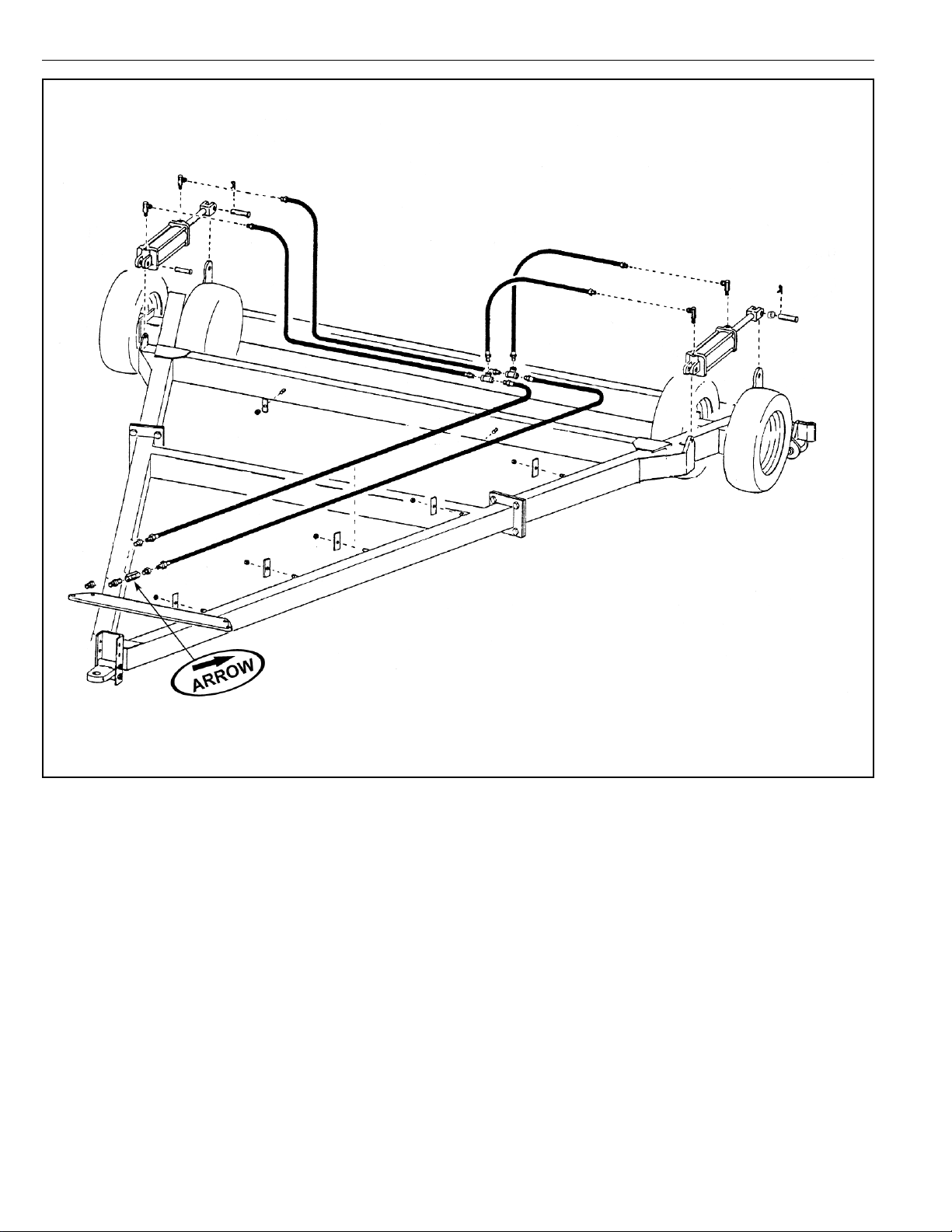
Fig. 20 Hydraulic Lift System - 20 ft. Hitch
2-6

SECTION 3 – SET-UP INSTRUCTIONS — SUPERHARROW
Fig. 1
The machine should be placed in an area that allows ample room for assembly in field position (See Fig. 1).
CAUTION: For safety purposes, block equipment while working on it.
Refer to illustrations and parts listing on pages 8-2 to 8-20 and follow these steps when assembling.
16’ HITCH ASSEMBLY
HITCH, HUBS AND WHEELS
Mount axle plates with spindles down for 1 1L tires and with spindles up for 14L tires. Mount hitch wheels and tires and install
hitch jack.
CENTER WING DRAWBAR TUBES FOR 16’ HITCH
Attach center tube to hitch using (2) 1-3/16” x 7-1/4” pins and secure with 7/16” x 3” bolts and locknuts. Attach wing tubes to
center tube knuckles using 1-1/4” x 7” pins. When in field position, the locking collar is on top. Insert a 7/16” x 3” bolt through
the locking collar and hole in the top of each pin and secure with locknut. Secure pin with 1” flat washer and 1” NC lock jam
nut.
IMPORT ANT: Be sure to install wing tube spindles with spindle down when in field position.
Mount support wheels and tires. Do not mount transport wheel assemblies until lift arms are positioned.
3-1

SECTION 3 – SET-UP INSTRUCTIONS — SUPERHARROW
Fig. 2
20’ HITCH ASSEMBLY
Bolt the two A-frame sections of the hitch together, using eight 7/8” cap screws and locknuts.
NOTE: Since these larger pieces have a tendency to warp when welded, it may be necessary to pull the legs of the hitch
together to match the center tube brackets.
HITCH, HUBS AND WHEELS
Mount axle plates with spindles down for 1 1L tires and with spindles up for 14L tires. Mount hitch wheels and tires and install
hitch jack.
CENTER WING DRAWBAR TUBES FOR 16’ HITCH
Attach center tube to hitch using (2) 1-3/16” x 9-1/2” pins. Secure with 7/16” x 3” bolts and locknuts. Att ach inside section of
split-wing with 1-1/4” x 7” pin and secure with 7/16” x 3” bolt and locknut. Secure pin with 1” flat washer and 1” NC lock jam
nut.
Attach outside wing and secure with 1-3/4” x 9-3/4” pin, 7/16” x 3-1/2” bolt and lock nut. Mount wing tube spindles with spindle
down in field position. Do not install transport wheel assemblies until lift arms are positioned.
SECTIONS:
Attach sections to drawbar using 3/4” U-bolts, nuts and lock washers as shown in figures 8 through 14.
3-2

SECTION 3 – SET-UP INSTRUCTIONS — SUPERHARROW
Use CAUTION when making manual height adjustments. For Safety purposes, block equipment while working on it.
On the center two sections only , move the lower stop bolt and bushing to the front hole (Fig. 12). This will allow the sections
to raise more evenly.
To compensate for various soil conditions and tooth wear , the sections can be mounted in four dif ferent positions as shown
below.
Height Adjustment
Suggested Lift Arm Center U-Bolt Plate Lift Arm / Spring Flat Ref.
Initial Setting 3” Above Drawbar Center Up Up Fig. 8
1-1/2” Above Drawbar Center Down Up Fig. 9
Even With Drawbar Center Up Down Fig. 10
1-1/2” Below Drawbar Center Down Down Fig. 11
Fig. 8 Fig. 9 Fig. 10
Fig. 11 Fig. 12
TRANSPORT WHEELS
Install transport wheels as shown in figures 1 and 13. Secure with two 5/8” x 5-1/2” bolts, lock washers and nuts.
NOTE: Transport wheel brackets are made for lef t and right and are not interchangeable.
IMPORT ANT : The positioning of the transport wheel assemblies on the wing tubes of the machine is very critical in determin-
ing hitch weight. Moving transport wheel assemblies forward will increase hitch weight and moving rearward will decrease
hitch weight. See the “Warning Regarding Machines With Negative Hitch Weight” on page 1-2 for more information.
3-3
SECTION 3 – SET-UP INSTRUCTIONS — SUPERHARROW
WING TUBE JACK BRACKET
A wing tube jack bracket is provided with all machines and allows for mounting the hitch jack on the wing tube for more
stability (See Fig. 6).
CABLES
Install cable brackets and cable assemblies as shown in figures 1, 2 and 7. Secure brackets using 3/4” U-bolts, lock washers
and nuts. Two cables are required for each wing on the split wing models.
NOTE: Adjust cables so wings slightly lead center when st anding in field position.
IMPORT ANT : On machines with two cables per wing, the cables must be adjusted so the out side wing slightly leads
the inside wing.
AUTO-FOLD CABLE FOLD OPTION
See Sections 5 and 6 for 16’ and 20’ hitch Auto-Fold instructions.
Fig. 6 Wing Tube Jack Bracket
Fig. 7 Mounting Cable Pull Clamps
3-4
3-5
Fig. 13 Superharrow Schematic Layout
SECTION 3 – SET-UP INSTRUCTIONS — SUPERHARROW
3-6
Fig. 14 Superharrow Spring Loaded Tine Angle
SECTION 3 – SET-UP INSTRUCTIONS — SUPERHARROW
SECTION 3 – SET-UP INSTRUCTIONS — SUPERHARROW
HYDRAULIC SYSTEMS FOR MACHINES WITH 16 OR 20 FT. HITCHES
Mount lift cylinders and assemble hose lines as shown in
figures 19 and 20.
NOTE: The hydraulic line leading from the rod-end of
the lift cylinders requires a restrictor valve on the tractor end. Thread this valve on with the arrow pointing
back towards the cylinders as illustrated.
Fig. 19 Hydraulic Lift System - 16 ft. Hitch
3-7
SECTION 3 – SET-UP INSTRUCTIONS — SUPERHARROW
Fig. 20 Hydraulic Lift System - 20 ft. Hitch
3-8
 Loading...