

Subaru Baja 2004 User Manual

FOREWORD
FOREWORD
1. Foreword
A: FOREWORD
These manuals are used when performing maintenance, repair, or diagnosis of the Subaru FORESTER.
Applied model: SG***** from 2004MY
The manuals contain the latest information at the
time of publication. Changes in specifications,
methods, etc. may be made without notice.
FW-2

HOW TO USE THIS MANUAL
HOW TO USE THIS MANUAL
1. How to Use This Manual
A: HOW TO USE THIS MANUAL
1. STRUCTURE
Each section consists of SCT that are broken down
into SC that are divided into sections for each component. The specification, maintenance and other
information for the components are included, and
diagnosis information has also been added where
necessary.
2. INDEX
The first page has an index with tabs.
HU-2

HOW TO USE THIS MANUAL
HOW TO USE THIS MANUAL
3. COMPONENTS
Illustrations are listed for each component. The information necessary for repair work (tightening torque,
grease up points, etc.) is described on these illustrations. Information is described using symbol. To order the
parts, refer to parts catalogue.
Example:
T2
(6)
(12)
(17)
(32)
T5
(37)
(14)
(19)
(3)
(4)
(22)
(34)
(5)
(33)
(20)
(16)
(18)
(7)
(8)
(21)
(23)
T1
(35)
T5
T3
T3
T3
T3
T3
(36)
(8)
T2
T2
(7)
T5
T1
T6
(10)
(16)
T3
(10)
(14)
(3)
(15)
T11
(4)
T10
(23)
T7
(18)
(1)
T6
(17)
(4)
T8
(2)
T1
T2
(22)
(10)
T6
(13)
(9)
(21)
(4)
(4)
(3)
(5)
T2
(3)
(24)
(25)
T2
(12)
(24)
(28)
T4
T2
T4
(10)
(29)
(25)
(6)
(11)
(26)
(30)
T1
(2)
(1)
(9)
(10)
(11)
T2
T4
T5
(27)
(31)
:Selective part
:Replacement part
:Sealing point
T3
(13)
(15)
T4
T9
(19)
(20)
HU-3
T1
:Should be lubricated with oil.
:Should be lubricated with grease.
,
T2
....
:Tightening torque
HU-00001

HOW TO USE THIS MANUAL
HOW TO USE THIS MANUAL
4. SPECIFICATIONS
If necessary, specifications are also included.
5. INSPECTION
Inspections are included to be carried out before and after maintenance.
6. MAINTENANCE
• Maintenance instructions for serviceable parts describes work area and detailed steps with illustration. It
also describes the use of special tool, tightening torque, cautions for each procedure.
• If many serviceable parts are included in one service procedure, appropriate reference are provided for
each part.
Example:
15.Main Shaft Assembly for Single-Range
A: REMOVAL
1) Remove the manual transmission assembly
from vehicie. <Ref. to MT-33, REMOVAL, Manual
Transmission Assembly.>
11) Tighten the lock nuts to the specified torque us-
ing ST1 and ST2.
NOTE:
Secure the lock nuts in two Places affer tightening.
ST2 499987003 SOCKET WRENCH
ST1 498937000 TRANSMISSION HOLDER
Tightening torque:
118 N m (12.0 kgf-m, 86.8 ft-lb)
(E) (F)
(A)
(B)
(C)
(D)
(G)
(H)
ST2
(A) Component (D) Caution (G) Tightening torque
(B) Process (E) Tool number of special tool (H) Illustration
(C) Reference (F) Name of special tool
ST1
HU-4
HU-00002

HOW TO USE THIS MANUAL
7. DIAGNOSIS
Tables showing a step-by-step process make it
easy to conduct diagnosis.
8. SI UNITS
Measurements in these manuals are according to
the SI units. Metric and yard/pound measurements
are also included.
Example:
Tightening torque:
44 N·m (4.5 kgf-m, 33 ft-lb)
HOW TO USE THIS MANUAL
HU-5

HOW TO USE THIS MANUAL
HOW TO USE THIS MANUAL
HU-6
IDENTIFICATION
IDENTIFICATION
1. Identification
A: IDENTIFICATION
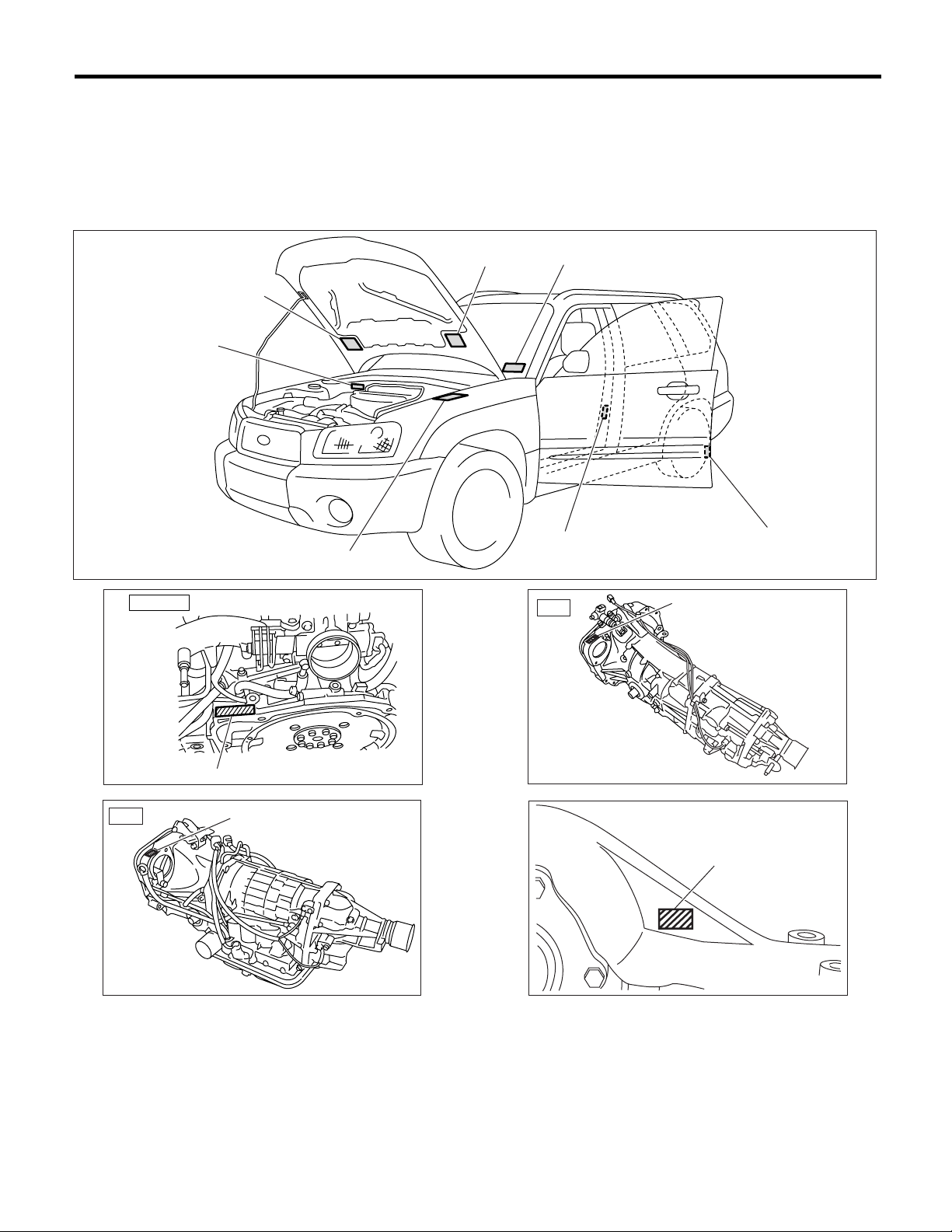
1. IDENTIFICATION NUMBER AND LABEL LOCATIONS
The VIN (Vehicle Identification Numbers) is used to classify the vehicle.
Positioning of the plate label for identification
Vacuum hose
piping label
Emission control label
Vehicle identification
number
Vehicle identification number plate
ENGINE
4AT
Engine serial number
Transmission serial number
Model number plate
ID-00011
Tire inflation
pressure label
5MT
Bar cord label
(America spec. vehicles only)
ID-00010
Transmission serial number
ID-00013
Stamp location
ID-00012
ID-00014
ID-2

IDENTIFICATION
Model number plate
trim code
Color code
2. MEANING OF V.I.N.
The meaning of the VIN is as follows:
]JF1SG636X4G700001[
The starting and ending brackets ( ][ ) are stop marks.
FUJI HEAVY INDUSTRIES LTD.
1SG
VIN
applied model
41
23
J
F
S
G
0
0
transmission type
63
9AY7J
engine type
G
5X3
option code
EJ251BWUAA
55
T
Y7
70000
0
E
VC3A
IDENTIFICATION
1
A
ID-00006
Digits Code Meaning Details
1 to 3 JF1 Manufacturer body area JF1: Passenger car, FHI made
4 S Car line S: Forester
5 G Body type G: Wagon
6 6 Displacement 6: 2.5L AWD
7 3 Grade 3: 2.5X
5: 2.5XS
9: 2.5XT
8 6 Restraint 6: Manual belts, dual airbag, side airbag
9 X Check digit X or 0 — 9
10 4 Model year 4: 2004MY
5: 2005MY
6: 2006MY
11 G Transmission type G: Full-time AWD 5-speed MT
H: Full-time AWD 4-speed AT
12 to 17 700001 Serial number —
ID-3

IDENTIFICATION
IDENTIFICATION
3. MODEL NUMBER PLATE
The model number plate indicates: the applied model, the option code, the trim code, the engine type, the
transmission type, and the exterior color code. This information is helpful when placing orders for parts.
SG9BY7J
Digits Code Meaning Details
1 S Series S: Forester
2 G Body type G: Wagon
3 9 Engine displacement
Drive system
Suspension system
4 B Model year B: 2004MY
5 Y Destination Y: U.S.A., Canada
6 7 Grade 7: 2.5X
7 J Transmission, fuel feed
system
The engine and transmission type are as follows:
• Engine
9: 2.5L AWD
8: 2.5XS
B: 2.5XT
J: SOHC MFI 5-speed MT
R: SOHC MFI 4-speed AT
D: DOHC Turbo MFI 5-speed MT
P: DOHC Turbo MFI 4-speed AT
EJ251BWTAA
Digits Code Meaning Details
1 and 2 EJ Engine type EJ: 4 cylinders
3 and 4 25 Displacement 25: 2.5L
5 1 Fuel feed system 1: D-MFI SOHC-A
5: MFI DOHC Turbo
6 B Exhaust regulations B: US Federal & California
7 W Transmission W: MT
X: AT
8 to 10 TAA Detailed specifications Used when ordering parts. See the parts catalog for details.
• Transmission
TY755VC4AA
Digits Code Meaning Details
1 T Transmission T: Transmission
2 Y Transmission type Y: Full-time AWD MT center differential
Z: Full-time AWD AT MPT
3 and 4 75 Classification 75: MT
1A: AT
1B: AT (Turbo)
55 Series 3: AT
5: MT, AT (Turbo)
6 V Transmission specifica-
tions
7 C Mounted body C: US 2.5L SOHC
8 to 10 4AA Detailed specifications Used when ordering parts. See the parts catalog for details.
V: Full-time AWD 5-speed MT with viscous coupling center differential single range
Z: Full-time AWD 4-speed AT with MPT
L: Full-time AWD 4-speed AT with MPT (Turbo)
H: 2.5L DOHC Turbo
ID-4

IDENTIFICATION
• Rear differential
T2
Code Reduction gear ratio LSD
T2 4.111 No
JP 4.111 Viscous
TP 4.444 No
CF 4.444 Viscous
• Option code
U4QW
Digits Code Meaning Details
1 to 2 U4 Destination U4: U.S.A.
CO: Canada
3 to 4 QW Main option of vehicle —
IDENTIFICATION
ID-5

IDENTIFICATION
IDENTIFICATION
ID-6

NOTE
1. Note
A: NOTE
This is information that can improve efficiency of
maintenance and assure sound work.
1. FASTENER NOTICE
Fasteners are used to prevent parts from damage
and dislocation due to looseness. Fasteners must
be tightened to the specified torque.
Do not apply paint, lubricant, rust retardant, or other substances to the surface around bolts, fasteners, etc. Doing so will make it difficult to obtain the
correct torque and result in looseness and other
problems.
2. STATIC ELECTRICITY DAMAGE
Do not touch the control unit, connectors, logic
boards, and other such parts when there is a risk of
static electricity. Always use a static electricity prevention cord or touch grounded metal before conducting work.
NOTE
3. BATTERY
When removing the battery cables, always be sure
to turn the ignition off to prevent electrical damage
to the control unit from rush current.
4. SERVICE PARTS
Use authentic service parts for maximum performance and maintenance, when conducting repairs.
Subaru/FHI will not be responsible for poor performance resulting from the use of parts not specified
by a genuine dealer.
5. PROTECTING VEHICLE UNDER MAINTENANCE
Make sure to attach the fender cover, seat covers,
etc. before work.
6. ENSURING SAFETY DURING WORK
When working in a group of two or more, perform
the work with calling each other to ensure mutual
safety.
NT-2
NOTE
NOTE
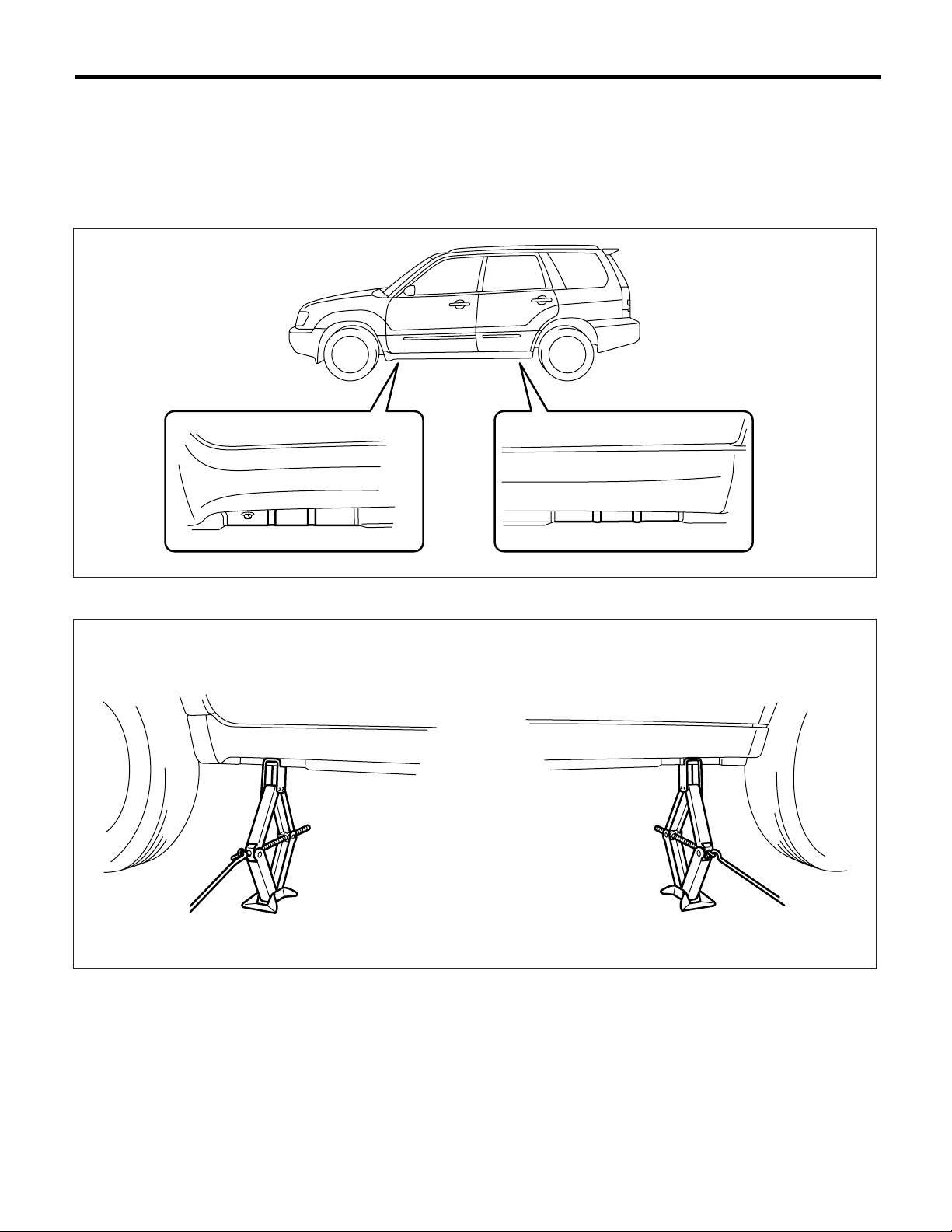
7. LIFTS AND JACKS
When using a lift or jack to raise a vehicle, always follow instructions concerning jack-up points and weight
limits to prevent the vehicle from falling, which could result in injury. Be especially careful to make sure the
vehicle is balanced before raising it.
Be sure to set the wheel stoppers when jacking-up only the front or rear of the vehicle.
• Support Locations
• Pantograph jack
NT-00001
NT-00002
NT-3
NOTE
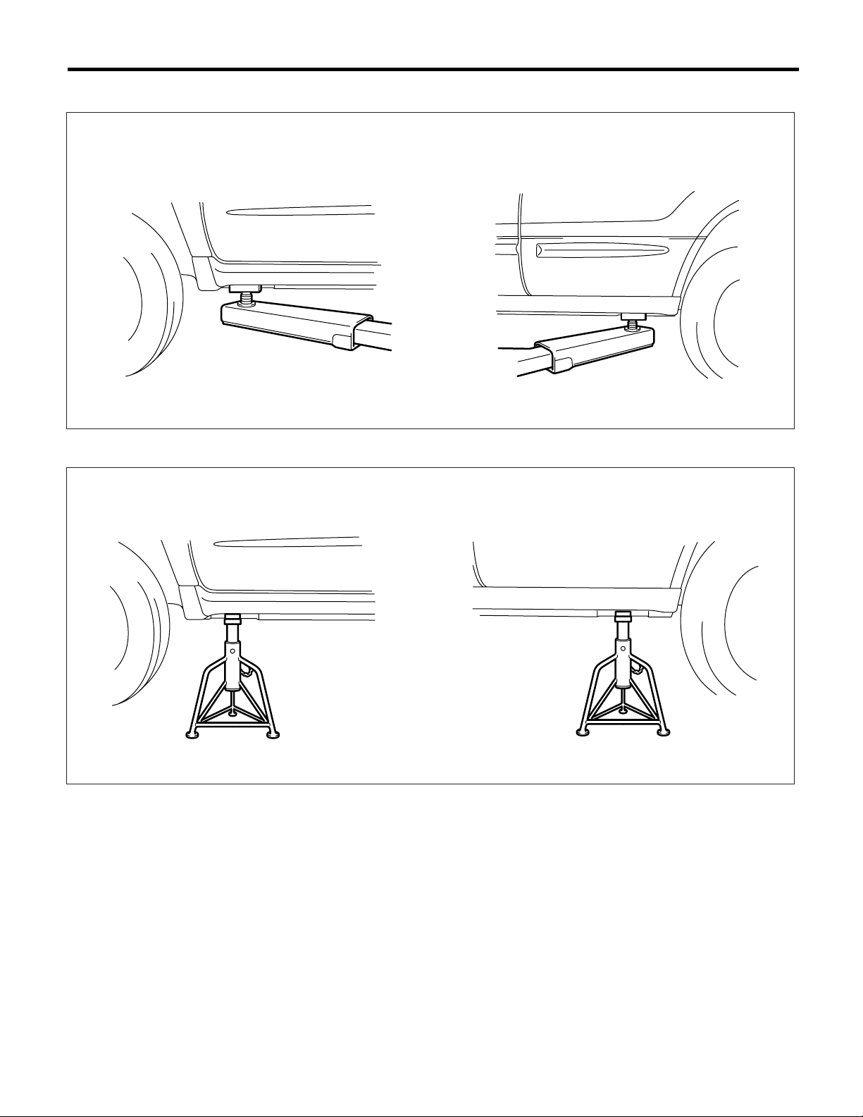
• Lift
• Safety stand
NOTE
NT-00003
NT-4
NT-00004

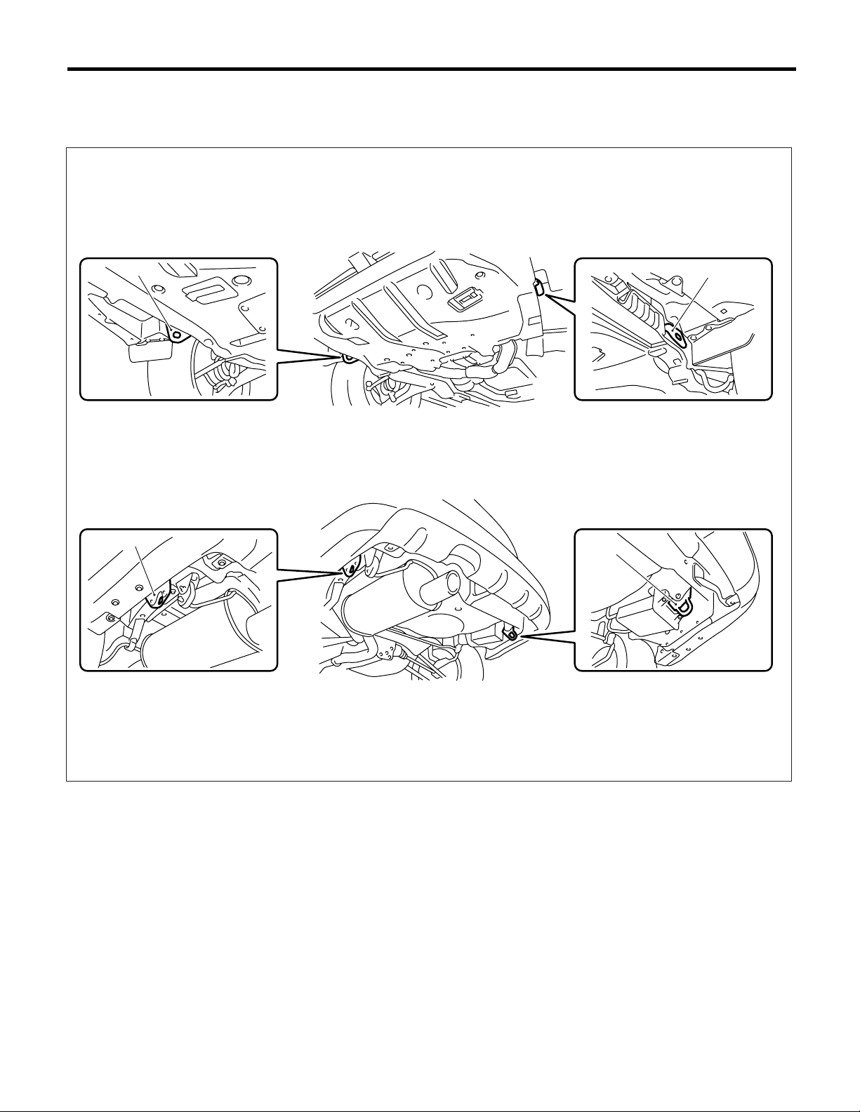
• Jack-up point
(A)
(B)
NOTE
NOTE
(A) Front
(B) Rear
NT-00005
NT-5
NOTE
NOTE
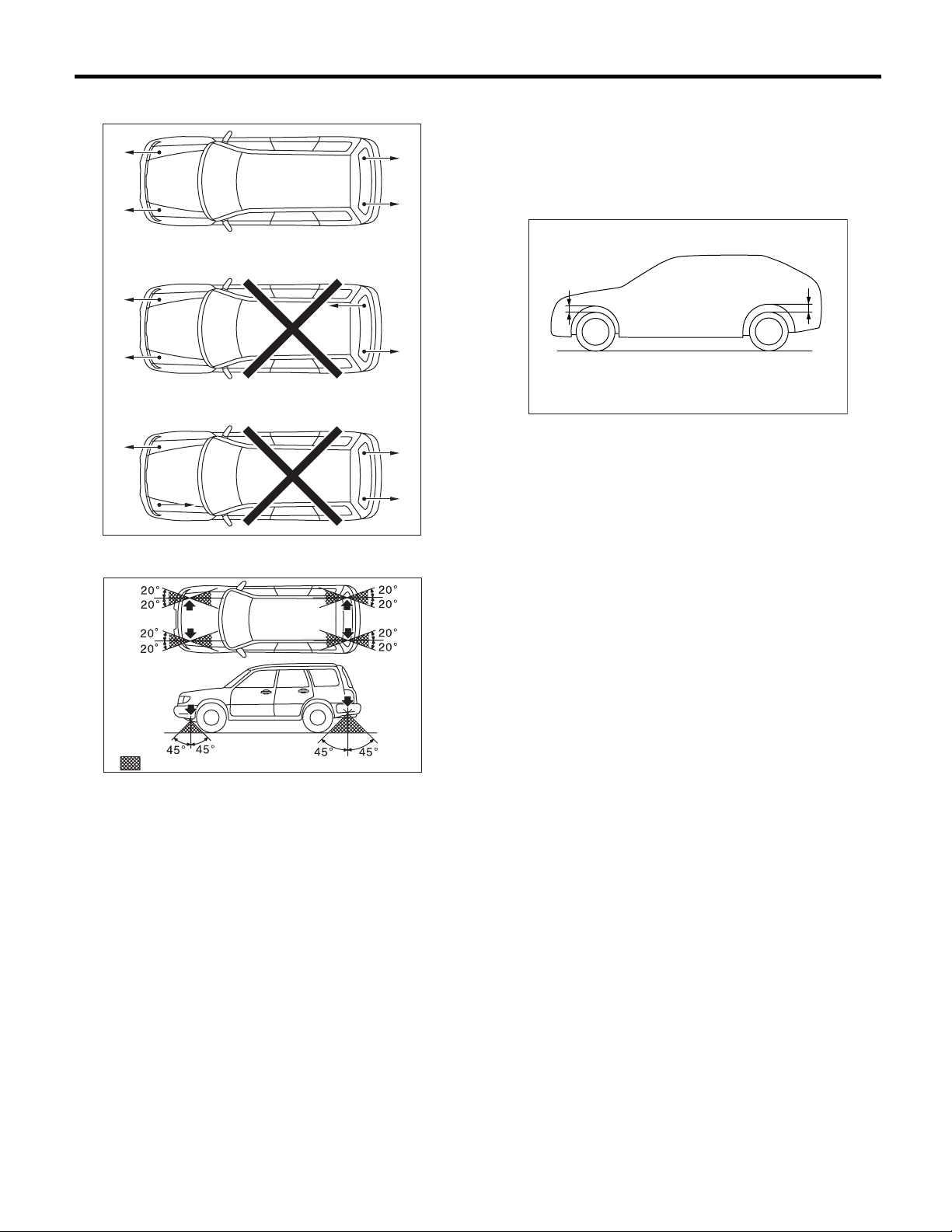
8. TIE-DOWNS
Tie-downs are used when transporting vehicles and when using the chassis dynamo. Attach tie-downs only
to the specified points on the vehicle.
(A)
(D)
(C)
(B)
(C)
(B)
(A) Front
(B) Hook for towing and tie-down
(C) Hook for tie-down
(D) Rear
NT-00006
NT-6
NOTE
NOTE
• Chain direction at tie-down condition
NT-00007
• Chain pulling range at tie-down condition
• Vehicle sinking volume at tie-down condition
Measure the distance L between tire highest point
to arch highest point before tie-down and after tiedown. Difference of measurement value (drop
height) shall be within 50 mm (1.97 in). Make sure
to fix the vehicle securely.
L
L
NT-00082
: (A)
(A) Chain pulling range at tie-down condition
NT-00008
9. TOWING
Avoid towing vehicles except when the vehicle cannot be driven. For models with AWD or AT use a loader
instead of towing. When towing other vehicles, to prevent excessive weight from damaging the hook or vehicle:
• Do not tow other vehicles with a front hook for tie-down.
• Make sure the vehicle towing is heavier that the vehicle being towed.
NT-7

NOTE
10.FRONT HOOD STAY INSTALLATION
• At the check and general maintenance
NOTE
NT-00009
• When wider hood opening is necessary
Set stay into the hole of hood inner as shown in the figure below.
NOTE:
Before setting the front hood in this position, remove the windshield washer hose attaching clip from the front
hood.
NT-00010
11.TRAINING
For information about training, contact a dealer or
agent.
12.GENERAL SCAN TOOL
Using general scan tools will greatly improve efficiency of repairing engine electronic controls. The
SUBARU Select Monitor can be used to diagnose
the engine and also the ABS, the air conditioner,
and other parts.
NT-8
PERIODIC MAINTENANCE SERVICES
COOLING SYSTEM
11.Cooling System
A: INSPECTION
1) Check the radiator for leakage, filling it with coolant and attach the radiator cap tester (A) to filler
neck.
PRESSURE:
157 kPa (1.6 kg/cm
Check the following points.
• Each portion of radiator for leakage
• Hose joints and other connections for leakage
CAUTION:
• For turbo model, be sure to install tester to
filler tank side.
• When attaching or detaching tester and when
operating tester, use special care not to deform
radiator filler neck.
• When performing this check, be sure to keep
the engine stationary and fill the radiator with
coolant.
• Wipe off check points before applying pressure.
• Use care not to spill coolant when detaching
the tester from radiator.
• Non-turbo model
2
, 23 psi)
CAUTION:
Rust or dirt on the cap may prevent the valve
from functioning normally: be sure to clean the
cap before testing.
Radiator cap valve open pressure
Standard value:
2
93 — 123 kPa (0.95 — 1.25 kg/cm
, 14 — 18
psi)
Service limit:
2
83 kPa (0.85 kg/cm
, 12 psi)
PM-00023
(A)
CO-00042
• Turbo model
(A)
CO-00043
2) Check the radiator cap valve open pressure using radiator cap tester.
Raise the pressure until the needle of gauge stops
and see if the pressure can be retained for 5 to 6
seconds. The radiator cap is normal if a pressure
above the service limit value has been maintained
for this period.
(A)
(A)
(A) Deformation
(B) Deformation, damage, rust
(B)
PM-00089
3) Start the engine, and then check if it does not
over heat or it is cooled excessively. If it overheats
or it is cooled excessively, check the cooling system. <Ref. to CO(H4SO)-19, Water Pump.> <Ref.
to CO(H4SO)-24, Thermostat.> <Ref. to
CO(H4SO)-26, Radiator.> <Ref. to CO(H4SO)-32,
Radiator Cap.>
4) Check the radiator fan operates using SUBARU
Select Monitor, when the coolant temperature exceeds 95°C (203°F). If not operate, check the radiator fan system. <Ref. to CO(H4SO)-11, Radiator
Fan System.>
PM-18

DISC BRAKE PADS AND DISCS
PERIODIC MAINTENANCE SERVICES
20.Disc Brake Pads and Discs
A: INSPECTION
1. DISC BRAKE PAD AND DISC
1) Lift-up the vehicle. Then remove the wheels.
2) Visually check the pad thickness through inspection hole of disc brake assembly. Replace the pad if
necessary.
CAUTION:
When replacing a pad, always replace the pads
for both the right and left wheels at the same
time. Also replace the pad clips if they are twisted or worn.
(A)
3) Check the disc rotor, and correct or replace if it is
damaged or worn.
Brake disc thickness mm (in)
Front Rear
Standard 24 (0.94) 10 (0.39)
Wear limit 22 (0.87) 8.5 (0.335)
4) Remove the caliper body. <Ref. to BR-18, Front
Disc Brake Assembly.> <Ref. to BR-24, Rear Disc
Brake Assembly.>
5) Tighten the wheel nuts to secure disk rotor.
6) Set a dial gauge at a point less than 10 mm (0.39
in) from outer periphery of rotor, and then measure
the disk rotor runout.
Disc rotor runout limit:
Front: 0.075 mm (0.0030 in)
Rear: 0.070 mm (0.0028 in)
PM-00049
(A) Inspection hole
Pad thickness including back metal mm (in)
Front Rear
Standard 17 (0.67) 14 (0.55)
Wear limit 7.5 (0.295) 6.5 (0.256)
(A)
(C)
(B)
PM-00050
(A) Thickness of pad
(B) Back metal
(C) Lining
PM-00051
PM-31
ENGINE OIL FILTER
PERIODIC MAINTENANCE SERVICES
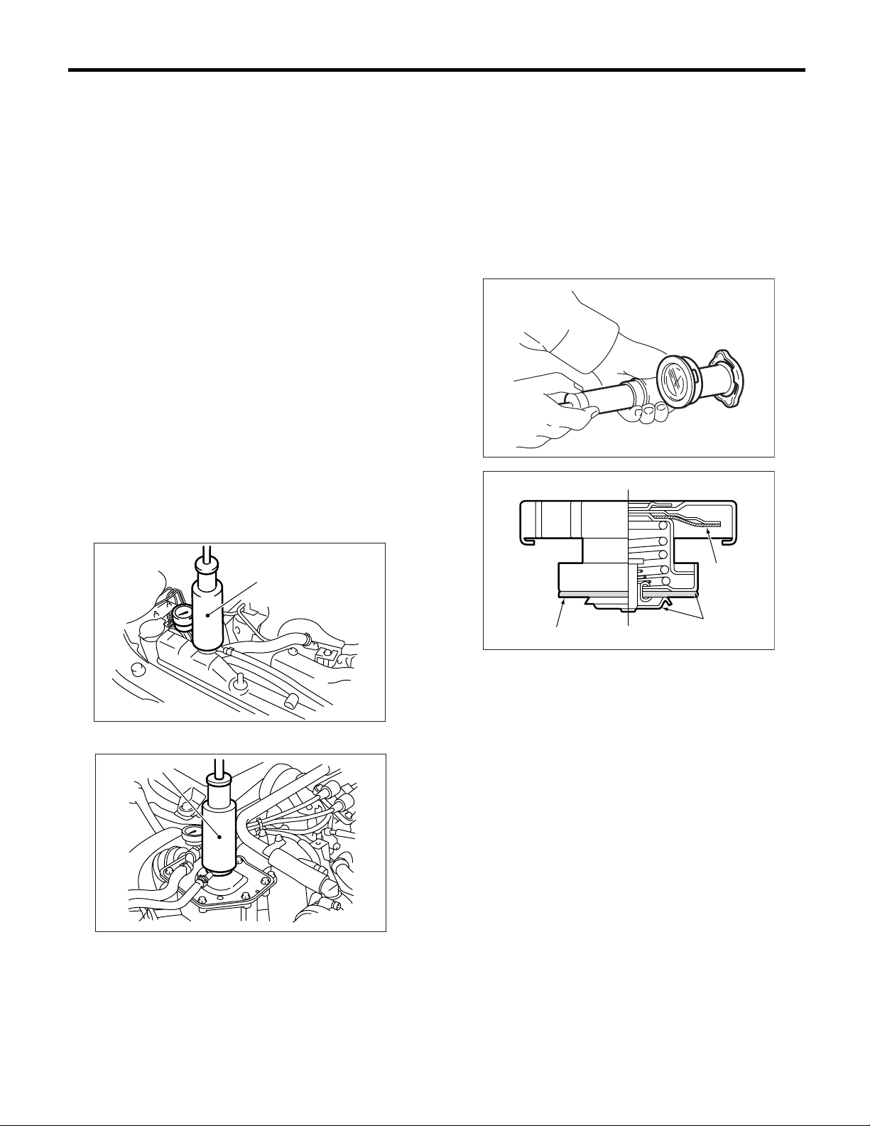
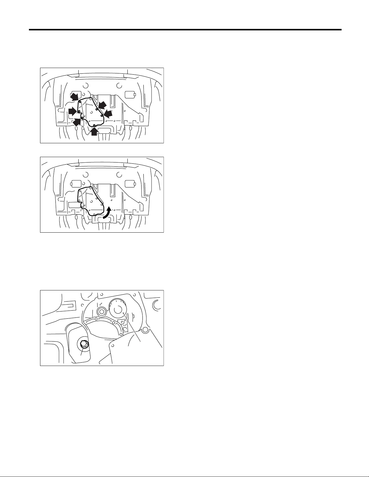
4. Engine Oil Filter
A: REPLACEMENT
1) Remove six clips securing service hole cover.
LU-00005
2) Turn the service hole cover counterclockwise.
6) Install the oil filter by turning it by hand, being
careful not to damage the seal rubber.
• Tighten the oil filter 80 mm (3.15 in) in diameter
by approx. 2/3 - 3/4 rotation more after the seal rubber of oil filter comes in contact with cylinder block
or oil cooler.
• Tighten the oil filter 68 mm (2.68 in) or 65 mm
(2.56 in) in diameter by approx. 1 rotation more after the seal rubber of oil filter comes in contact with
cylinder block or oil cooler.
CAUTION:
Do not tighten excessively, or oil may leak.
7) After installing the oil filter, run the engine and
make sure that no oil is leaking around seal rubber.
NOTE:
The filter element and filter case are permanently
joined; therefore, interior cleaning is not necessary.
8) Check the engine oil level. <Ref. to PI-3, PDI
PROCEDURE, Pre-delivery Inspection.>
LU-00006
3) Remove the oil filter with ST.
ST 498547000 OIL FILTER WRENCH (Outer
diameter: 80 mm (3.15 in))
ST 18332AA000 OIL FILTER WRENCH (Outer
diameter: 68 mm (2.68 in))
ST 18332AA010 OIL FILTER WRENCH (Outer
diameter: 65 mm (2.56 in))
(B)
(A)
(A) Engine oil drain plug
(B) Engine oil filter
LU-00007
4) Wipe clean the oil filter matching surface on cylinder block or oil cooler.
5) Get a new engine oil filter and apply a thin coat of
engine oil to the seal rubber.
CAUTION:
Be careful not to use the oil filter 80 mm (3.15 in)
in diameter to turbo model.
PM-7
 Loading...