

Page 1

2004 Model Year
PDF Service Manual
GENERAL INFORMATION SECTION (Pub.No.G1870GE1)
ENGINE SECTION 1 (Pub.No.G1870GE2)
ENGINE SECTION 2 (Pub.No.G1870GE3)
TRANSMISSION SECTION (Pub.No.G1870GE4)
CHASSIS SECTION (Pub.No.G1870GE5)
BODY SECTION (Pub.No.G1870GE6)
WIRING SYSTEM SECTION (Pub.No.G1870GE7)
Page 2

Page 3
2004 IMPREZA SERVICE MANUAL QUICK REFERENCE INDEX
GENERAL INFORMATION
SECTION
FOREWORD FW
HOW TO USE THIS MANUAL HU
SPECIFICATIONS SPC
PRECAUTION PC
This service manual has been prepared
to provide SUBARU service personnel
with the necessary information and data
for the correct maintenance and repair
of SUBARU vehicles.
This manual includes the procedures
for maintenance, disassembling, reassembling, inspection and adjustment of
components and diagnostics for guidance of experienced mechanics.
Please peruse and utilize this manual
fully to ensure complete repair work for
satisfying our customers by keeping
their vehicle in optimum condition.
When replacement of parts during
repair work is needed, be sure to use
SUBARU genuine parts.
NOTE NT
IDENTIFICATION ID
RECOMMENDED MATERIALS RM
PRE-DELIVERY INSPECTION PI
PERIODIC MAINTENANCE SERVICES PM
All information, illustration and specifications contained in this manual are
based on the latest product information
available at the time of publication
approval.
FUJI HEAVY INDUSTRIES LTD. G1870GE1
Page 4

Page 5

FOREWORD
1. Foreword .....................................................................................................2
FW
Page
Page 6

Foreword
FOREWORD
1. Foreword
A: FOREWORD
These manuals are used when performing maintenance, repair, or diagnosis of the Subaru IMPREZA.
Applied model:
GD*****, GG***** from 2004MY
The manuals contain the latest information at the
time of publication. Changes in specifications,
methods, etc. may be made without notice.
FW-2
Page 7

HOW TO USE THIS MANUAL
1. How to Use This Manual .............................................................................2
HU
Page
Page 8

How to Use This Manual
HOW TO USE THIS MANUAL
1. How to Use This Manual
A: HOW TO USE THIS MANUAL
1. STRUCTURE
Each section consists of SCT that are broken down
into SC that are divided into sections for each component. The specification, maintenance and other
information for the components are included, and
diagnosis information has also been added where
necessary.
2. INDEX
The first page has an index with tabs.
3. COMPONENTS
Illustrations are listed for each component. The information necessary for repair work (tightening
torque, grease up points, etc.) is described on
these illustrations. Information is described using
symbol. To order the parts, refer to parts catalogue.
HU-2
Page 9
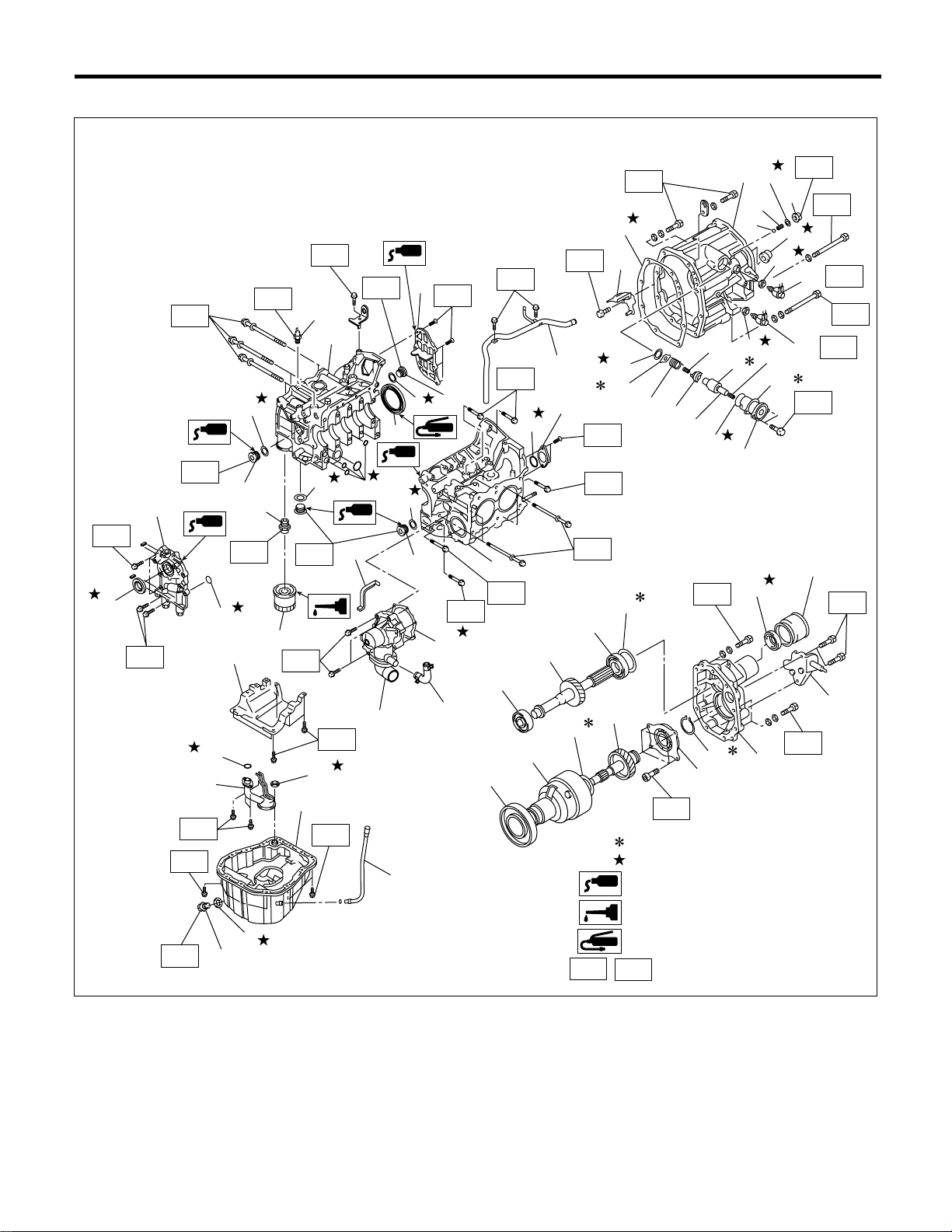
Example:
T2
(8)
T2
(7)
T5
T1
T6
(10)
(16)
T3
(10)
(14)
(3)
(15)
T11
(4)
T10
(23)
T7
(18)
How to Use This Manual
T8
(5)
(1)
T6
(17)
(4)
T6
(2)
(9)
(10)
(22)
(13)
T2
T1
(21)
(4)
(4)
(3)
T2
(3)
(12)
T4
T2
(24)
(24)
(25)
(28)
T2
T4
(10)
(29)
(25)
(6)
(11)
(26)
(30)
T1
(2)
(1)
(9)
(10)
(11)
T2
T4
T5
(27)
(31)
:Selective part
:Replacement part
:Sealing point
HOW TO USE THIS MANUAL
(6)
(12)
(17)
(32)
T5
(37)
(14)
(19)
(3)
(4)
(22)
(34)
(5)
(33)
(7)
(8)
(20)
(23)
(16)
(18)
T5
T3
(13)
(15)
T4
T2
(21)
T1
(35)
T3
T3
T3
T3
T3
(36)
T9
(19)
(20)
HU-3
T1
:Should be lubricated with oil.
:Should be lubricated with grease.
,
T2
....
:Tightening torque
HU-00017
Page 10
How to Use This Manual
HOW TO USE THIS MANUAL
4. SPECIFICATIONS
If necessary, specifications are also included.
5. INSPECTION
Inspections are included to be carried out before and after maintenance.
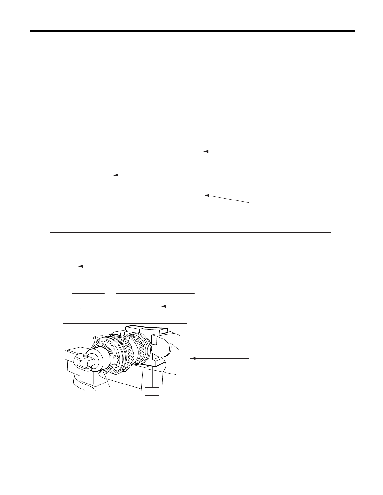
6. MAINTENANCE
• Maintenance instructions for serviceable parts describes work area and detailed steps with illustration. It
also describes the use of special tool, tightening torque, cautions for each procedure.
• If many serviceable parts are included in one service procedure, appropriate reference are provided for
each part.
Example:
15.Main Shaft Assembly for Single-Range
A: REMOVAL
1) Remove the manual transmission assembly
from vehicie. <Ref. to MT-33, REMOVAL, Manual
Transmission Assembly.>
11) Tighten the lock nuts to the specified torque us-
ing ST1 and ST2.
NOTE:
Secure the lock nuts in two Places affer tightening.
ST2 499987003 SOCKET WRENCH
ST1 498937000 TRANSMISSION HOLDER
Tightening torque:
118 N m (12.0 kgf-m, 86.8 ft-lb)
(E) (F)
(A)
(B)
(C)
(D)
(G)
(H)
ST2
(A) Component (D) Caution (G) Tightening torque
(B) Process (E) Tool number of special tool (H) Illustration
(C) Reference (F) Name of special tool
ST1
HU-4
HU-00002
Page 11
How to Use This Manual
HOW TO USE THIS MANUAL
7. DIAGNOSIS
Tables showing a step-by-step process make it easy to conduct diagnosis.
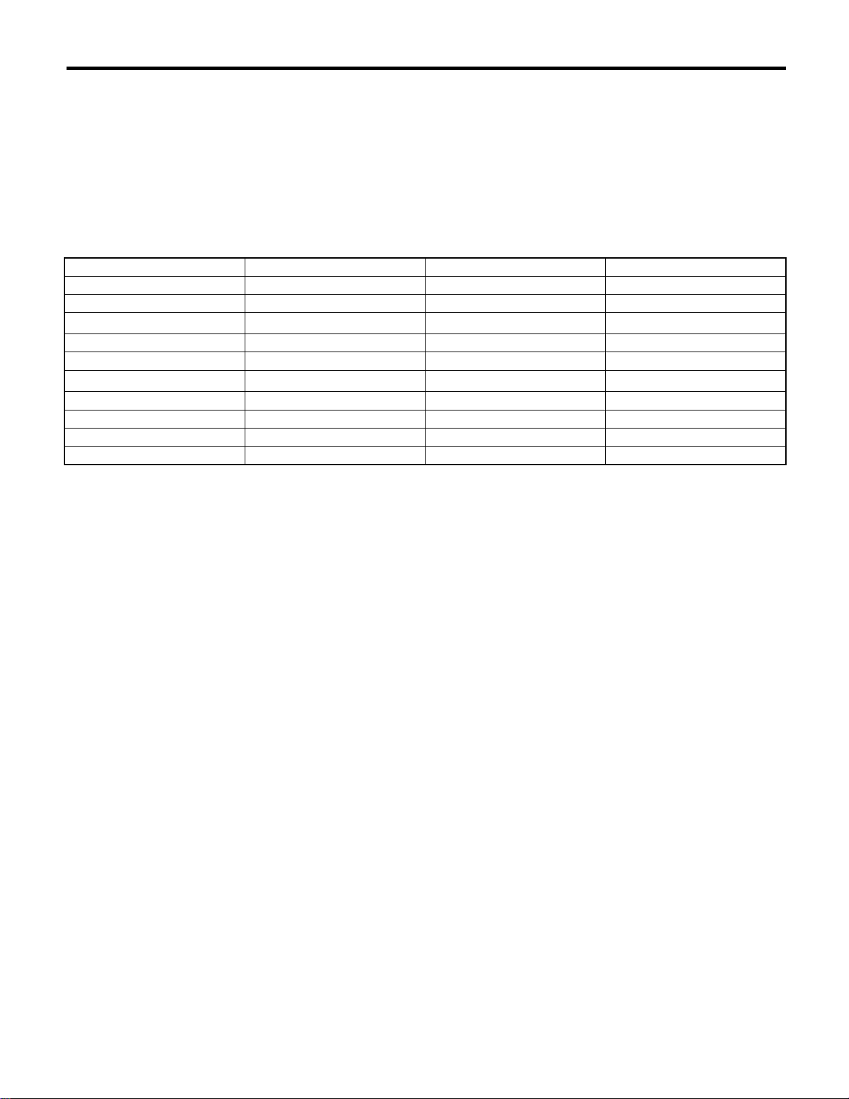
8. SI UNITS
Measurements in these manuals are according to the SI units. Metric and yard/pound measurements are
also included.
Example:
Tightening torque:
44 N·m (4.5 kgf-m, 33 ft-lb)
Item SI Units Conventional unit Remarks
Force N (Newton) kgf 1 kgf = 9.80655 N
Mass (Weight) kg, g kg, g
Capacity
Torque N·m kgf-m, kgf-cm 1 kgf-m = 9.80655 N·m
Rotating speed rpm rpm
Pressure kPa (kilopascal)
Power W PS 1 PS = 0.735499 kW
Calorie W⋅h cal 1 kcal = 1.16279 W⋅h
Fuel consumption rate g/kw⋅hg/PS⋅h1 g/PS⋅h = 1.3596 g/kW⋅h
2, m2 or cm
3
2 or cc
2
kgf/cm
mmHg 1 mmHg = 0.133322 kPa
1 cc = 1 cm
1 kgf/cm2 = 98.0655 kPa
3
= 1 m2
The figure used in this manuals are described in the SI units and conventional units are described in ( ).
HU-5
Page 12

How to Use This Manual
HOW TO USE THIS MANUAL
9. EXPLANATION OF TERMINOLOGY
• List
AAI : Air Assist Injection LH : LH (Left Hand)
A/B : Airbag LSD : Limited Slip Differential
ABS : Antilock Brake System M/B : Main Fuse & Relay Box
A/C : Air conditioner MD : Mini Disc
A/F : Air Fuel Ratio MPi : Multi Point injection
ALT : Generator MP-T : Multi-Plate Transfer
ASSY : Assembly MT : Manual transmission
AT : Automatic transmission NonATF : Automatic transmission fluid
AVCS : Active Valve Control System NC : Normal Close (Relay)
AWD : All Wheel Drive NO : Normal Open (Relay)
BATT : Battery OP : Option Parts
CD-R/RW : CD Recordable/ReWritable P/S : Power Steering
COMPL : Complete P/W : Power Window
CPU : Central Processing Unit PCD : Pitch Circle Diameter
DOHC : Double Overhead Camshaft PCV : Positive Crankcase Ventilation
ECM : Engine Control Module (ECM) RH : RH (Right Hand)
EGI : Electronic Gasoline Injection SOHC : Single Overhead Camshaft
E/G : Engine SRC : Supplemental Restraint System
EGR : Exhaust Gas Recirculation SSM : Subaru Select Monitor
ELR : Emergency Locking Retractor ST : Special Tool
F/B : Fuse & Joint Box SW : Switch
FL : Fusible Link TGV : Tumble generated valve
FWD : Front Wheel Drive T/M : Transmission
HID : High-Intensity Discharge ViS-C : Viscous Coupling
H/U : Hydraulic Unit VSV : Vacuum Switching Valve
IG : Ignition VTD : Variable Torque Distribution
IN : Intake W/H : Wiring harness
INT : Intermittent Pr : Primary
ISC : Idle Speed Control 2ndr : Secondary
turbo
: Natural Aspiration
HU-6
Page 13
SPECIFICATIONS
1. Impreza .......................................................................................................2
SPC
Page
Page 14
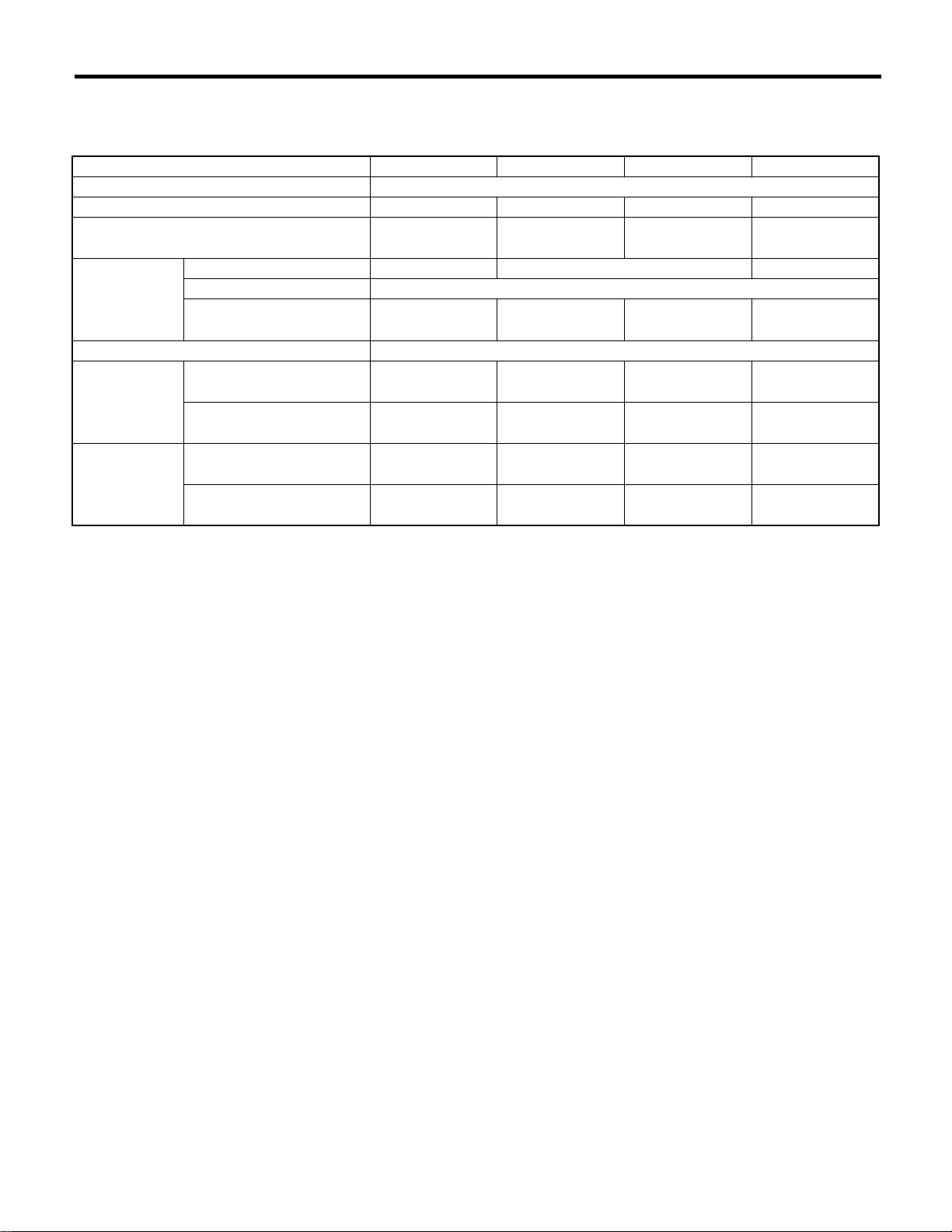
Impreza
SPECIFICATIONS
1. Impreza
A: DIMENSIONS
Model Sedan Wagon OUTBACK STi
Overall length mm (in) 4,415 (173.8)
Overall width mm (in) 1,740 (68.4) 1,695 (66.7) 1,710 (67.3) 1,740 (68.1)
Overall height (at C.W.) mm (in)
1,440 (56.7)
Compartment Length mm (in) 1,890 (74.4) 1,845 (72.6) 1,890 (74.4)
Width mm (in) 1,380 (54.3)
Height mm (in) 1,180 (46.5),
1,125 (44.3)
★5
Wheelbase mm (in) 2,525 (99.4)
Tread Front mm (in)
1,485 (58.5)
Rear mm (in) 1,475 (58.1),
★3
★2
★3
Minimum road
clearance
★1
: 1.6 L
★2
: 2.0 L
★3
: 2.0 L Turbo
★4
: With roof rail
★5
: With sun roof
Without catalytic
converter
With catalytic
converter
1,480 (58.3)
mm (in) 150 (5.9),
155 (6.1)
mm (in) 150 (5.9),
155 (6.1)
1,465 (57.7),
1,485 (58.5)
★4
1,200 (47.2),
1,150 (45.3)
★5
1,460 (57.5)★1,
1,465 (57.7)
1,450 (57.1)★1,
1,455 (57.3)
150 (5.9),
155 (6.1)
★2
150 (5.9),
155 (6.1)
★3
1,475 (58.1),
1,495 (58.9)
1,200 (47.2),
1,150 (45.3)
★4
★5
1,440 (56.7)
1,180 (46.5)
1,460 (57.5) 1,490 (58.7)
1,455 (57.3) 1,480 (58.3)
160 (6.3) —
160 (6.3) 155 (6.1)
SPC-2
Page 15
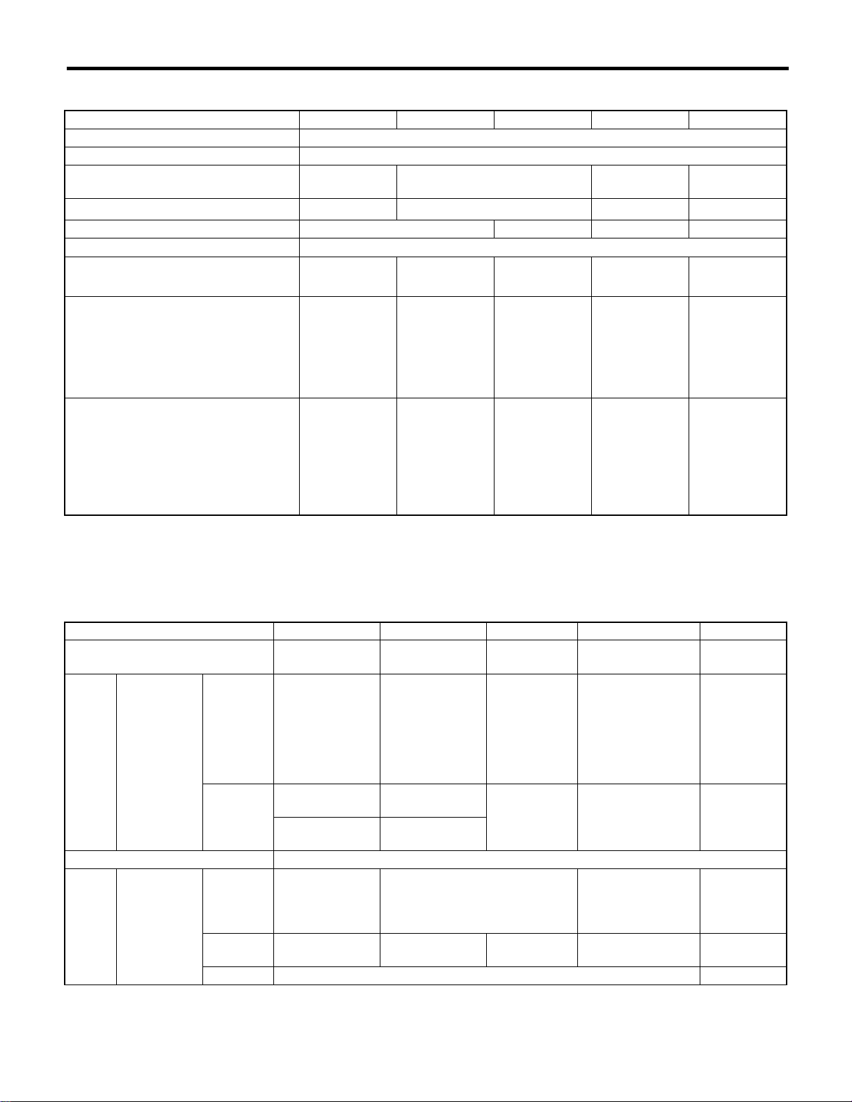
Impreza
SPECIFICATIONS
B: ENGINE
Model 1.6 L Non-turbo 2.0 L Turbo 2.0 L 2.5 L STi
Engine type Horizontally opposed, liquid cooled, 4-cylinder, 4-stroke gasoline engine
Valve arrangement Overhead camshaft type
Bore × Stroke mm (in) 87.9 × 65.8
(3.461 × 2.591)
Displacement
cm3 (cu in)
1,597 (97.45) 1,994 (121.67) 2,457 (149.9) 1,994 (121.67)
Compression ratio 10.0±0.2 8.0±0.2 10.0±0.2 8.0±0.2
Firing order 1 — 3 — 2 — 4
Idle speed at
Park/Neutral position
rpm
650±100
700±100
★2
★1
650±100
700±100
Maximum output kW (HP)/rpm
70
(94)/5,200
(123)/5,600
Maximum torque N·m (kgf-m, ft-lb)
/rpm
143
★1
: Without OBD
★2
: With OBD
★3
: Australia model
★4
: Europe model
(14.6, 105.5)
/3,600
(18.8, 136.0)
/3,600
(3.62 × 2.95)
★2
★1
92
184
92 × 75
(225)/6,000
(221)/5,600
700±100
★4
750±100
160
(215)/5,600
168
165
292
(29.8, 215.4)
/3,600
300
(30.6, 221.3)
★3
/3,600
4,000
,
★4
★3
★4
99.5 × 79
(3.92 × 3.11)
92 × 75
(3.62 × 2.95)
650±100 700±100
112
(150)/5,600
223
(22.7, 164.5)
/3,600
195
(261)/6,000
343
(35.0, 253.0)
/4,000
C: ELECTRICAL
Model 1.6 L Non-turbo 2.0 L Turbo 2.0 L 2.5 L STi
Ignition timing at
idling
Spark
plug
Type and
manufacturer
Generator 12V — 75A
Battery Type and
capacity
(5HR)
BTDC
Without
OBD
5°±10° 10°±10° 12°±10°
NGK: BKR6E
(without catalyst)
CHAMPION:
RC8YC4
(with catalyst)
NGK: BKR6E-11
(with catalyst)
With OBD CHAMPION:
RC8YC4
Alternate
NGK: BKR6E-11
NGK: BKR6E
(without catalyst)
CHAMPION:
RC10YC4
(with catalyst)
NGK: BKR5E-11
(with catalyst)
CHAMPION:
RC10YC4
Alternate
NGK: BKR5E-11
—
NGK: PFR6G — NGK: PFR6G
MT: 10°±10°
AT: 15°±10°
CHAMPION:
RC10YC4
NGK: BKR5E-11
12°±10°
For
Europe
and South
12V — 48AH
(55D23L)
MT: 12V — 48AH (55D23L)
AT: 12V — 52AH (65D23L)
—
12V — 48AH
(55D23L)
America
For
Australia
—
12V — 27AH
(34B19L)
12V — 40AH
(50D20L)
12V — 27AH
(34B19L)
12V — 40AH
(50D20L)
Others 12V — 27AH (34B19L) —
—
SPC-3
Page 16
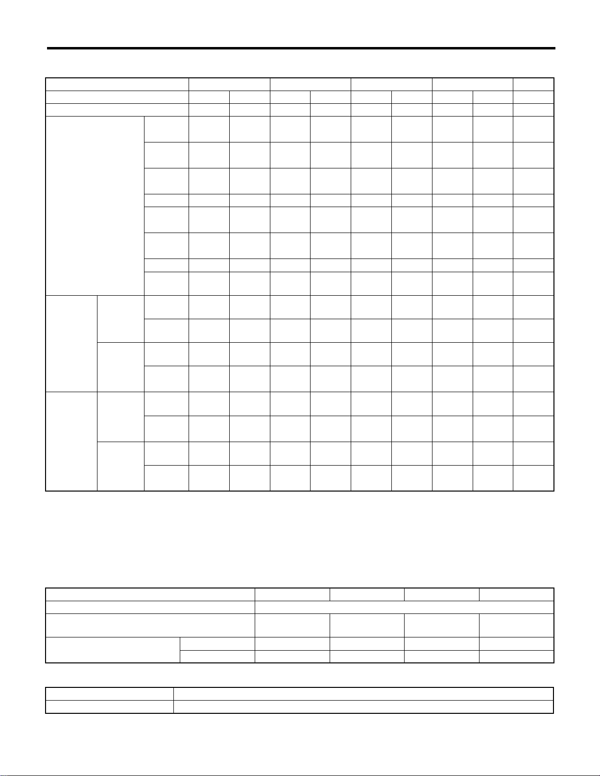
Impreza
SPECIFICATIONS
D: TRANSMISSION
Model 1.6 L Non-turbo 2.0 L Turbo 2.0 L 2.5 L STi
Transmission type 5MT 4AT 5MT 4AT 5MT 4AT 5MT 4AT 6MT
Clutch type DSPD TCC DSPD TCC DSPD TCC DSPD TCC DSPD
Gear ratio 1st
2nd
3rd
4th 1.088 0.694 1.088 0.694 0.972 0.694 1.088 0.694 1.346
5th
6th
Reverse 3.333 2.272 3.333 2.272 3.333 2.272 3.333 2.272 3.545
Dual
range
Reduction
gear (Front
drive)
Reduction
gear (Rear
drive)
(AWD
model)
1st
reduction
Final
reduction
Transfer
reduction
Final
reduction
Type of
gear
Gear
ratio
Type of
gear
Gear
ratio
Type of
gear
Gear
ratio
Type of
gear
Gear
ratio
3.454 2.785 3.454 2.785
2.062 1.545 2.062 1.545
1.448 1.000 1.448 1.000
0.825 — 0.825 — 0.738 —
————————
1.447 — 1.447 ——————
— Helical — Helical — Helical — Helical —
— 1.000 — 1.000 — 1.000 — 1.000 —
Hypoid Hypoid Hypoid Hypoid Hypoid Hypoid Hypoid Hypoid Hypoid
4.111 4.444 3.900 4.111
Helical — Helical — Helical — Helical — Helical
1.000 — 1.000 —
Hypoid Hypoid Hypoid Hypoid Hypoid Hypoid Hypoid Hypoid Hypoid
4.111 4.444 3.900 4.111
3.454,
3.166
1.947,
1.882
1.366,
1.296
3.900,
4.444
1.100,
1.000
3.545,
4.444
2.785 3.454 2.785 3.636
★1
1.545 2.062 1.545 2.375
★1
1.000 1.448 1.000 1.761
★1
0.871,
★1
0.780
4.444 4.111 4.111 3.900
★1
★1
★1
— 1.000 —
4.444 4.111 4.111
—
0.971,
1.062
0.756,
0.842
1.100,
1.000
3.545,
3.900
★1
★1
★1
★1
5MT: 5-forward speeds with synchromesh and 1-reverse
4AT: Electronically controlled fully-automatic, 4-forward speeds and 1-reverse
6MT: 6-forward speeds with synchromesh and 1-reverse
DSPD: Dry Single Plate Diaphragm
TCC: Torque Converter Clutch
★1
: Australia spec vehicle
E: STEERING
Model Turbo 2.0 L, 2.5 L OUTBACK 2.0 L NA, 1.6 L STi
Type Rack and Pinion
Turns, lock to lock RHD: 2.69
LHD: 3.02
Minimum turning circle m (ft) Curb to curb 11 (36.1) 11 (36.1) 10.4 (34.1) 11 (36.1)
Wall to wall 12.0 (39.4) 11.6 (38.1) 11.2 (36.7) 12.0 (39.4)
3.02 3.22 2.69
F: SUSPENSION
Front Macpherson strut type, Independent, Coil spring
Rear Dual-link type, Independent, Coil spring
SPC-4
Page 17
Impreza
SPECIFICATIONS
G: BRAKE
Model 1.6 L Non-turbo 2.0 L, 2.5 L Turbo 2.0 L, STi
Service brake system Dual circuit hydraulic with vacuum suspended power unit
Front Ventilated disc brake
Rear Drum brake Disc brake Ventilated disc brake
Parking brake Mechanical on rear brakes
H: TIRE
Model BASE, TS GX, TS RS, WRX OUTBACK WRX STi
Rim size
Tire size 185/70R14 88H 195/60R15 88H 205/50R16 87V P205/55R16 89V 215/45R17 87W 225/45R17 90W
Type Steel belted radial, Tubeless
14 × 51/2JJ
15 × 6JJ
16 × 61/2JJ 16 × 61/2JJ
17 × 7JJ
17 × 71/2JJ
I: CAPACITY
Model 1.6 L FWD 1.6 L AWD Non-turbo 2.0 L Turbo 2.0 L 2.5 L STi
5MT 4AT 5MT 4AT 5MT 4AT 5MT 4AT 5MT 4AT 6MT
Fuel tank 2 (US gal,
Imp gal)
Engine
oil
Transmission
gear oil
ATF 2 (US qt,
Front differential
gear oil
Rear differential
gear oil
Power steering
fluid
Engine coolant 2 (US qt,
Total
capacity
Engine
oil
amount
for refill
★1
: Dual range
2 (US qt,
Imp qt) 4.0 (4.2, 3.5) 4.5 (4.8, 4.0) 4.0 (4.2, 3.5)
2 (US qt,
Imp qt)
2 (US qt,
Imp qt)
Imp qt) —
2 (US qt,
Imp qt) —
2 (US qt,
Imp qt) — 0.8 (0.8, 0.7)
2 (US qt,
Imp qt)
Imp qt)
3.3
(3.5,
2.9)
7.4
(7.8,
6.5)
8.0
(8.5,
7.0)
1.2
(1.3,
1.1)
7.3
(7.7,
6.4)
50 (13.2, 11.0) 60 (15.9, 13.2)
Approx. 4.0 (4.2, 3.5)
—
3.5
(3.7,
3.1),
4.0
(4.2,
3.5)
(7.8,
6.5)
—
—
7.4
—
★1
8.4
(8.9,
7.4)
1.2
(1.3,
1.1)
7.3
(7.7,
6.4)
3.5
(3.7,
3.1),
4.0
(4.2, 3.5)
★1
—
—
7.0
(7.4,
6.2)
—
8.4
(8.9,
7.4)
1.2
(1.3,
1.1)
0.7 (0.7, 0.6)
6.9
(7.3,
6.1)
3.5
(3.7,
3.1)
—
—
7.7
(8.1,
6.8)
—
9.3
(9.8,
8.2)
1.2
(1.3,
1.1)
7.6
(8.0,
6.7)
3.5
(3.7,
3.1)
—
—
7.0
(7.4,
6.2)
—
9.3
(9.8,
8.2)
1.2
(1.3,
1.1)
6.9
(7.3,
6.1)
4.5
(4.8,
4.0)
4.1
(4.3,
3.6)
1.0
(1.1,
0.9)
7.7
(8.1,
6.8)
—
—
SPC-5
Page 18
Impreza
SPECIFICATIONS
J: WEIGHT
1. LHD MODEL
Sedan
Option code
Model 1.6 L
Curb weight (C.W.) Front kgf (lb) 720
Maximum permissible
axle weight (M.P.A.W.)
Maximum permissible
weight (M.P.W.)
Option Air conditioner ❍❍❍— ❍❍❍❍
★1
★1
5MT 4AT 5MT
(1,587)
Rear kgf (lb) 470
(1,036)
Total kgf (lb) 1,190
(2,624)
Front kgf (lb) 890
(1,962)
Rear kgf (lb) 890
(1,962)
Total kgf (lb) 1,660
(3,660)
ABS ——❍❍❍———
Side airbag ————————
Sunroof ————————
Aluminium wheel ————————
Audio ————————
Seat in pure hide ————————
Rear spoiler ————————
Front LSD ————————
Driver’s control
center differential
: For option code, refer to ID section. <Ref. to ID-7, Option code.>
————————
E2
FWD AWD
Base TS
765
(1,687)
470
(1,036)
1,235
(2,723)
890
(1,962)
890
(1,962)
1,660
(3,660)
770
(1,698)
470
(1,036)
1,240
(2,734)
890
(1,962)
890
(1,962)
1,660
(3,660)
735
(1,620)
520
(1,146)
1,255
(2,756)
890
(1,962)
890
(1,962)
1,700
(3,748)
EC
755
(1,664)
520
(1,146)
1,275
(2,810)
890
(1,962)
890
(1,962)
1,700
(3,748)
K0
750
(1,654)
520
(1,146)
1,270
(2,800)
890
(1,962)
890
(1,962)
1,700
(3,748)
K4 KS
750
(1,654)
520
(1,146)
1,270
(2,800)
890
(1,962)
890
(1,962)
1,700
(3,748)
740
(1,631)
535
(1,179)
1,275
(2,810)
890
(1,962)
890
(1,962)
1,700
(3,748)
SPC-6
Page 19
Impreza
SPECIFICATIONS
Option code
Model 1.6 L 2.0 L
Curb weight (C.W.) Front kgf (lb) 755
Maximum permissible
axle weight (M.P.A.W.)
Maximum permissible
weight (M.P.W.)
Option Air conditioner — ❍❍❍❍— ❍❍
★1
★1
Rear kgf (lb) 520
Total kgf (lb) 1,275
Front kgf (lb) 890
Rear kgf (lb) 890
Total kgf (lb) 1,700
ABS ❍❍———❍❍❍
Side airbag ———————❍
Sunroof ————————
Aluminium wheel ———————❍
Audio ————————
Seat in pure hide ————————
Rear spoiler ————————
Front LSD ————————
Driver’s control
center differential
: For option code, refer to ID section. <Ref. to ID-7, Option code.>
EC K0
TS GX
4AT 5MT
775
(1,644)
(1,146)
(2,810)
(1,962)
(1,962)
(3,748)
————————
(1,709)
520
(1,146)
1,295
(2,855)
890
(1,962)
890
(1,962)
1,700
(3,748)
770
(1,698)
520
(1,146)
1,290
(2,844)
890
(1,962)
890
(1,962)
1,700
(3,748)
K4
770
(1,698)
520
(1,146)
1,290
(2,844)
890
(1,962)
890
(1,962)
1,700
(3,748)
AWD
KS
760
(1,676)
530
(1,168)
1,295
(2,855)
890
(1,962)
890
(1,962)
1,700
(3,748)
750
(1,654)
535
(1,179)
1,285
(2,833)
950
(2,094)
910
(2,006)
1,760
(3,880)
EC
770
(1,698)
535
(1,179)
1,305
(2,877)
950
(2,094)
910
(2,066)
1,760
(3,880)
765
(1,687)
535
(1,179)
1,300
(2,866)
950
(2,094)
910
(2,066)
1,760
(3,880)
SPC-7
Page 20
SPECIFICATIONS
Impreza
Option code
Model 2.0 L
Curb weight (C.W.) Front kgf (lb) 770
Maximum permissible
axle weight (M.P.A.W.)
Maximum permissible
weight (M.P.W.)
Option Air conditioner ❍❍❍❍❍❍— ❍
★1
★1
(1,698)
Rear kgf (lb) 535
(1,179)
Total kgf (lb) 1,305
(2,877)
Front kgf (lb) 950
(2,094)
Rear kgf (lb) 910
(2,066)
Total kgf (lb) 1,760
(3,880)
ABS ❍❍❍❍❍❍❍❍
Side airbag — ❍ ——————
Sunroof —————❍ ——
Aluminium wheel — ❍ — ❍ ————
Audio ————————
Seat in pure hide ————————
Rear spoiler —————❍ ——
Front LSD ————————
Driver’s control
center differential
: For option code, refer to ID section. <Ref. to ID-7, Option code.>
E2 K4 K0
AWD
GX
5MT 4AT
765
(1,687)
535
(1,179)
1,300
(2,866)
950
(2,094)
910
(2,066)
1,760
(3,880)
————————
770
(1,698)
535
(1,179)
1,305
(2,877)
950
(2,094)
910
(2,066)
1,760
(3,880)
765
(1,687)
530
(1,168)
1,295
(2,855)
950
(2,094)
910
(2,066)
1,760
(3,880)
760
(1,676)
525
(1,157)
1,285
(2,833)
950
(2,094)
910
(2,066)
1,760
(3,880)
KS
765
(1,687)
560
(1,235)
1,325
(2,921)
950
(2,094)
910
(2,066)
1,760
(3,880)
775
(1,709)
530
(1,168)
1,305
(2,877)
950
(2,094)
910
(2,006)
1,760
(3,880)
EC
795
(1,753)
530
(1,168)
1,325
(2,921)
950
(2,094)
910
(2,006)
1,760
(3,880)
SPC-8
Page 21
Impreza
SPECIFICATIONS
Option code
Model
Curb weight (C.W.) Front kgf (lb) 790
Maximum permissible
axle weight (M.P.A.W.)
Maximum permissible
weight (M.P.W.)
Option Air conditioner ❍❍❍❍❍❍❍❍
★1
★1
Rear kgf (lb) 530
Total kgf (lb) 1,320
Front kgf (lb) 950
Rear kgf (lb) 910
Total kgf (lb) 1,760
ABS ❍❍❍❍❍❍❍❍
Side airbag ❍ — ❍ —————
Sunroof ——————❍ —
Aluminium wheel ❍ — ❍ — ❍ — ❍ —
Audio ———————❍
Seat in pure hide ————————
Rear spoiler ——————❍❍
Front LSD ————————
Driver’s control
center differential
: For option code, refer to ID section. <Ref. to ID-7, Option code.>
EC E2 K4 K0 KS EC
2.0 L
AWD
GX WRX
4AT 5MT
795
(1,742)
(1,168)
(2,910)
(2,094)
(2,006)
(3,880)
————————
(1,742)
530
(1,168)
1,325
(2,921)
950
(2,094)
910
(2,006)
1,760
(3,880)
790
(1,742)
530
(1,168)
1,320
(2,910)
950
(2,094)
910
(2,006)
1,760
(3,880)
795
(1,753)
530
(1,168)
1,325
(2,921)
950
(2,094)
910
(2,006)
1,760
(3,880)
790
(1,742)
525
(1,157)
1,315
(2,899)
950
(2,094)
910
(2,006)
1,760
(3,880)
795
(1,753)
530
(1,168)
1,325
(2,921)
950
(2,094)
910
(2,006)
1,760
(3,880)
790
(1,753)
555
(1,224)
1,325
(2,921)
950
(2,094)
910
(2,006)
1,760
(3,880)
2.0 L
Turbo
835
(1,841)
560
(1,235)
1,395
(3,075)
990
(2,185)
920
(2,028)
1,850
(4,079)
SPC-9
Page 22
SPECIFICATIONS
Impreza
Option code
Model 2.0 L Turbo
Curb weight (C.W.) Front kgf (lb) 820
Maximum permissible
axle weight (M.P.A.W.)
Maximum permissible
weight (M.P.W.)
Option Air conditioner — ❍❍❍❍❍❍❍
★1
★1
835
(1,808)
Rear kgf (lb) 550
(1,213)
Total kgf (lb) 1,370
(3,020)
Front kgf (lb) 990
(2,185)
Rear kgf (lb) 920
(2,028)
Total kgf (lb) 1,850
(4,079)
ABS ❍❍❍❍❍❍❍❍
Side airbag ——❍❍❍——❍
Sunroof ———❍ — ❍❍❍
Aluminium wheel ————————
Audio ——————❍❍
Seat in pure hide ———❍ ——— ❍
Rear spoiler ————❍❍❍❍
Front LSD ————————
Driver’s control
center differential
: For option code, refer to ID section. <Ref. to ID-7, Option code.>
————————
(1,841)
555
(1,224)
1,390
(3,065)
990
(2,185)
920
(2,028)
1,850
(4,079)
835
(1,841)
560
(1,235)
1,395
(3,075)
990
(2,185)
920
(2,028)
1,850
(4,079)
840
(1,852)
570
(1,257)
1,410
(3,109)
990
(2,185)
920
(2,028)
1,850
(4,079)
EC
AWD
WRX
5MT
835
(1,840)
565
(1,246)
1,400
(3,087)
990
(2,185)
920
(2,028)
1,850
(4,079)
840
(1,852)
570
(1,257)
1,410
(3,109)
990
(2,185)
920
(2,028)
1,850
(4,079)
840
(1,852)
570
(1,257)
1,410
(3,109)
990
(2,183)
920
(2,028)
1,850
(4,079)
840
(1,852)
575
(1,268)
1,415
(3,120)
990
(2,183)
920
(2,028)
1,850
(4,079)
SPC-10
Page 23
Impreza
SPECIFICATIONS
Option code
Model 2.0 L Turbo
Curb weight (C.W.) Front kgf (lb) 835
Maximum permissible
axle weight (M.P.A.W.)
Maximum permissible
weight (M.P.W.)
Option Air conditioner ❍❍❍❍— ❍❍—
★1
★1
(1,840)
Rear kgf (lb) 560
(1,235)
Total kgf (lb) 1,395
(3,075)
Front kgf (lb) 990
(2,183)
Rear kgf (lb) 920
(2,028)
Total kgf (lb) 1,850
(4,079)
ABS ❍❍❍❍❍❍❍❍
Side airbag — ❍❍—————
Sunroof — ❍❍—————
Aluminium wheel ————————
Audio —————❍ ——
Seat in pure hide ——❍ —————
Rear spoiler ❍❍❍—————
Front LSD ———❍❍❍❍❍
Driver’s control
center differential
: For option code, refer to ID section. <Ref. to ID-7, Option code.>
——————❍❍
K4
AWD
WRX STi
5MT
840
(1,852)
575
(1,268)
1,415
(3,120)
990
(2,183)
920
(2,028)
1,850
(4,079)
840
(1,852)
575
(1,268)
1,415
(3,120)
990
(2,183)
920
(2,028)
1,850
(4,079)
885
(1,951)
585
(1,290)
1,470
(3,241)
1,030
(2,271)
920
(2,028)
1,880
(4,145)
865
(1,907)
585
(1,290)
1,450
(3,197)
1,030
(2,271)
920
(2,028)
1,880
(4,145)
(1,951)
(1,290)
1,470
(3,241)
1,030
(2,271)
(2,028)
1,880
(4,145)
EC
885
585
920
885
(1,951)
585
(1,290)
1,470
(3,241)
1,030
(2,271)
920
(2,028)
1,880
(4,145)
865
(1,907)
585
(1,290)
1,450
(3,197)
1,030
(2,271)
920
(2,028)
1,880
(4,145)
SPC-11
Page 24
Impreza
SPECIFICATIONS
Wagon
Option code
Model 1.6 L
Curb weight (C.W.) Front kgf (lb) 740
Maximum permissible
axle weight (M.P.A.W.)
Maximum permissible
weight (M.P.W.)
Option Air conditioner ——❍❍❍❍——
★1
D/R: Dual range
★1
(1,631)
Rear kgf (lb) 545
(1,202)
Total kgf (lb) 1,285
(2,833)
Front kgf (lb) 900
(1,984)
Rear kgf (lb) 910
(2,006)
Total kgf (lb) 1,730
(1,609)
ABS ❍❍❍———❍❍
Side airbag — ❍ —————❍
Sunroof ————————
Aluminium wheel ————————
Audio — ❍ —————❍
Seat in pure hide ————————
Spoiler pack ————————
: For option code, refer to ID section. <Ref. to ID-7, Option code.>
EC K0
5MT D/R 4AT
740
(1,631)
550
(1,213)
1,290
(2,844)
900
(1,984)
910
(2,006)
1,730
(1,609)
760
(1,676)
545
(1,202)
1,305
(2,877)
900
(1,984)
910
(2,006)
1,730
(1,609)
755
(1,664)
545
(1,202)
1,300
(2,866)
900
(1,984)
910
(2,006)
1,730
(1,609)
AWD
TS
K4
755
(1,664)
545
(1,202)
1,300
(2,866)
900
(1,984)
910
(2,006)
1,730
(1,609)
KS EC
745
(1,643)
560
(1,235)
1,305
(2,877)
900
(1,984)
910
(2,006)
1,730
(1,609)
755
(1,664)
545
(1,202)
1,300
(2,866)
900
(1,984)
910
(2,006)
1,730
(1,609)
755
(1,664)
550
(1,213)
1,305
(2,877)
900
(1,984)
910
(2,006)
1,730
(1,609)
SPC-12
Page 25
Impreza
SPECIFICATIONS
Option code
Model 1.6 L 2.0 L
Curb weight (C.W.) Front kgf (lb) 775
Maximum permissible
axle weight (M.P.A.W.)
Maximum permissible
weight (M.P.W.)
Option Air conditioner ❍❍❍❍— ❍❍❍
★1
D/R: Dual range
★1
Rear kgf (lb) 545
Total kgf (lb) 1,320
Front kgf (lb) 900
Rear kgf (lb) 910
Total kgf (lb) 1,730
ABS ❍ ———❍❍❍❍
Side airbag —————❍ — ❍
Sunroof —————❍ ——
Aluminium wheel ———————❍
Audio —————❍ ——
Seat in pure hide ————————
Spoiler pack ————————
: For option code, refer to ID section. <Ref. to ID-7, Option code.>
EC
(1,709)
(1,202)
(2,910)
(1,984)
(2,006)
(1,609)
K0
770
(1,698)
545
(1,202)
1,315
(2,899)
900
(1,984)
910
(2,006)
1,730
(1,609)
K4
TS GX
4AT 5MT D/R
770
(1,698)
545
(1,202)
1,315
(2,899)
900
(1,984)
910
(2,006)
1,730
(1,609)
KS
760
(1,676)
560
(1,235)
1,320
(2,910)
900
(1,984)
910
(2,006)
1,730
(1,609)
AWD
760
(1,676)
570
(1,257)
1,330
(2,932)
950
(2,094)
960
(2,0116)
1,800
(3,969)
785
(1,731)
585
(1,290)
1,370
(3,020)
950
(2,094)
960
(2,116)
1,800
(3,969)
EC
780
(1,720)
570
(1,257)
1,350
(2,977)
950
(2,094)
960
(2,116)
1,800
(3,969)
775
(1,709)
570
(1,257)
1,345
(2,965)
950
(2,094)
960
(2,116)
1,800
(3,969)
SPC-13
Page 26
SPECIFICATIONS
Impreza
Option code
Model 2.0 L
Curb weight (C.W.) Front kgf (lb) 780
Maximum permissible
axle weight (M.P.A.W.)
Maximum permissible
weight (M.P.W.)
Option Air conditioner ❍❍❍❍— ❍❍❍
★1
D/R: Dual range
★1
Rear kgf (lb) 570
Total kgf (lb) 1,350
Front kgf (lb) 950
Rear kgf (lb) 960
Total kgf (lb) 1,800
ABS ❍❍❍❍❍❍❍❍
Side airbag —————❍ — ❍
Sunroof ———❍ — ❍ ——
Aluminium wheel ——❍❍———❍
Audio —————❍ ——
Seat in pure hide ————————
Spoiler pack ————————
: For option code, refer to ID section. <Ref. to ID-7, Option code.>
K0
(1,720)
(1,257)
(2,977)
(2,094)
(2,116)
(3,969)
K4 KS
AWD
GX
5MT D/R 4AT
780
(1,720)
570
(1,257)
1,350
(2,977)
950
(2,094)
960
(2,116)
1,800
(3,969)
775
(1,709)
565
(1,246)
1,340
(2,955)
950
(2,094)
960
(2,116)
1,800
(3,969)
770
(1,698)
590
(1,300)
1,360
(2,999)
950
(2,094)
960
(2,116)
1,800
(3,969)
775
(1,709
565
(1,246)
1,340
(2,955)
950
(2,094)
960
(2,116)
1,800
(3,969)
(1,764)
(1,279)
(3,042)
(2,094)
(2,116)
(3,969)
800
580
1,380
950
960
1,800
EC
795
(1,753)
565
(1,246)
1,360
(2,999)
950
(2,094)
960
(2,116)
1,800
(3,969)
790
(1,742)
565
(1,246)
1,355
(2,987)
950
(2,094)
960
(2,116)
1,800
(3,969)
SPC-14
Page 27
Impreza
SPECIFICATIONS
Option code
Model 2.0 L 2.0 L Turbo
Curb weight (C.W.) Front kgf (lb) 795
Maximum permissible
axle weight (M.P.A.W.)
Maximum permissible
weight (M.P.W.)
Option Air conditioner ❍❍❍❍— ❍❍❍
★1
D/R: Dual range
★1
Rear kgf (lb) 565
Total kgf (lb) 1,360
Front kgf (lb) 950
Rear kgf (lb) 960
Total kgf (lb) 1,800
ABS ❍❍❍❍❍❍❍❍
Side airbag ——————❍❍
Sunroof ———❍ ——❍❍
Aluminium wheel ——❍❍————
Audio ———————❍
Seat in pure hide ——————❍ —
Spoiler pack ————————
: For option code, refer to ID section. <Ref. to ID-7, Option code.>
K0
(1,753)
(1,246)
(2,999)
(2,094)
(2,116)
(3,969)
K4 KS
AWD
GX WRX
4AT 5MT
795
(1,753)
565
(1,246)
1,360
(2,999)
950
(2,094)
960
(2,116)
1,800
(3,969)
790
(1,742)
560
(1,235)
1,350
(2,977)
950
(2,094)
960
(2,116)
1,800
(3,969)
790
(1,742)
580
(1,279)
1,370
(3,020)
950
(2,094)
960
(2,116)
1,800
(3,969)
805
(1,775)
585
(1,290)
1,390
(3,065)
990
(2,183)
950
(2,094)
1,860
(4,101)
825
(1,819)
585
(1,290)
1,410
(3,109)
990
(2,183)
950
(2,094)
1,860
(4,101)
EC
830
(1,830)
600
(1,322)
1,430
(3,153)
990
(2,183)
950
(2,094)
1,860
(4,101)
830
(1,830)
600
(1,322)
1,430
(3,153)
990
(2,183)
950
(2,094)
1,860
(4,101)
SPC-15
Page 28
SPECIFICATIONS
Impreza
Option code
Model 2.0 L Turbo
Curb weight (C.W.) Front kgf (lb) 830
Maximum permissible
axle weight (M.P.A.W.)
Maximum permissible
weight (M.P.W.)
Option Air conditioner ❍❍
★1
D/R: Dual range
★1
Rear kgf (lb) 600
Total kgf (lb) 1,430
Front kgf (lb) 990
Rear kgf (lb) 950
Total kgf (lb) 1,860
ABS ❍❍
Side airbag ❍❍
Sunroof ❍❍
Aluminium wheel ——
Audio ❍ —
Seat in pure hide ❍ —
Spoiler pack ——
: For option code, refer to ID section. <Ref. to ID-7, Option code.>
EC
(1,830)
(1,322)
(3,153)
(2,183)
(2,094)
(4,101)
K4
AWD
WRX
5MT
830
(1,830)
595
(1,311)
1,425
(3,142)
990
(2,183)
950
(2,094)
1,860
(4,101)
SPC-16
Page 29
Impreza
SPECIFICATIONS
2. RHD MODEL
Sedan
Option code
Model 1.6 L 2.0 L
Curb weight (C.W.) Front kgf (lb) 740
Maximum permissible
axle weight (M.P.A.W.)
Maximum permissible
weight (M.P.W.)
Option Air conditioner — ❍ — ❍❍❍❍❍
★1
★1
(1,631)
Rear kgf (lb) 520
(1,146)
Total kgf (lb) 1,260
(2,778)
Front kgf (lb) 890
(1,962)
Rear kgf (lb) 890
(1,962)
Total kgf (lb) 1,700
(3,748)
ABS ❍❍❍——❍❍❍
Side airbag ————————
Sunroof ————————
Aluminium wheel —————❍❍—
Audio ————————
Seat in pure hide ————————
Rear spoiler —————❍❍—
Spoiler pack —————❍❍—
Front LSD ————————
Cruise control ————————
: For option code, refer to ID section. <Ref. to ID-7, Option code.>
EK
TS GX
5MT 4AT 5MT 4AT 5MT 4AT 5MT
760
(1,676)
520
(1,146)
1,280
(2,822)
890
(1,962)
890
(1,962)
1,700
(3,748)
760
(1,676)
520
(1,146)
1,280
(2,822)
890
(1,962)
890
(1,962)
1,700
(3,748)
750
(1,654)
520
(1,146)
1,270
(2,800)
890
(1,962)
890
(1,962)
1,700
(3,748)
K1
AWD
770
(1,698)
520
(1,146)
1,290
(2,844)
890
(1,962)
890
(1,962)
1,700
(3,748)
EK K1
770
(1,698)
535
(1,179)
1,305
(2,877)
950
(2,094)
910
(2,006)
1,760
(3,880)
795
(1,753)
530
(1,168)
1,325
(2,921)
950
(2,094)
910
(2,006)
1,760
(3,880)
770
(1,698)
535
(1,179)
1,305
(2,877)
950
(2,094)
910
(2,006)
1,760
(3,880)
SPC-17
Page 30
SPECIFICATIONS
Impreza
Option code
Model 2.0 L 2.0 L Turbo
Curb weight (C.W.) Front kgf (lb) 795
Maximum permissible
axle weight (M.P.A.W.)
Maximum permissible
weight (M.P.W.)
Option Air conditioner ❍❍❍❍❍❍❍
★1
★1
Rear kgf (lb) 530
Total kgf (lb) 1,325
Front kgf (lb) 950
Rear kgf (lb) 910
Total kgf (lb) 1,760
ABS ❍❍❍❍❍❍❍
Side airbag — ❍ — ❍❍——
Sunroof ———❍❍——
Aluminium wheel ———————
Audio ———————
Seat in pure hide ————❍ ——
Rear spoiler — ❍❍❍❍——
Spoiler pack ——————❍
Front LSD ————— ❍ —
Cruise control ——————❍
: For option code, refer to ID section. <Ref. to ID-7, Option code.>
K1 EK
AWD
GX WRX STi
4AT 5MT 6MT
(1,753)
(1,168)
(2,921)
(2,094)
(2,006)
(3,880)
835
(1,841)
565
(1,246)
1,400
(3,086)
990
(2,183)
920
(2,028)
1,850
(4,079)
835
(1,841)
560
(1,246)
1,395
(3,075)
990
(2,183)
920
(2,028)
1,850
(4,079)
840
(1,852)
570
(1,257)
1,410
(3,109)
990
(2,183)
920
(2,028)
1,850
(4,079)
840
(1,852)
575
(1,268)
1,415
(3,120)
990
(2,183)
920
(2,028)
1,850
(4,079)
885
(1,952)
585
(1,290)
1,470
(3,241)
1,030
(2,271)
920
(2,028)
1,880
(4,145)
885
(1,952)
585
(1,290)
1,470
(3,241)
1,030
(2,271)
920
(2,028)
1,880
(4,145)
SPC-18
Page 31
Impreza
SPECIFICATIONS
Option code
Model 2.0 L 2.5 L 2.0 L Turbo
Unladen weight (U.W.) Front kg (lb) 750
Gross vehicle mass
(G.V.M.)
Option Air conditioner — ❍ — ❍❍❍❍❍
★1
★1
GX RS WRX
5MT 4AT 5MT 4AT 5MT
765
(1,654)
Rear kg (lb) 535
(1,179)
Total kg (lb) 1,285
(2,833)
Front kg (lb) 950
(2,094)
Rear kg (lb) 910
(2,006)
Total kg (lb) 1,760
(3,880)
ABS ❍❍❍❍❍❍❍❍
Side airbag ——————❍ —
Sunroof ——————❍ —
Aluminium wheel — ❍ — ❍ ————
Audio ————————
Seat in pure hide ——————❍ —
Rear spoiler — ❍ — ❍❍❍❍❍
Spoiler pack — ❍ — ❍ ————
Front LSD ————————
Cruise control ❍❍❍❍❍❍❍❍
Driver’s control
center differential
: For option code, refer to ID section. <Ref. to ID-7, Option code.>
————————
(1,687)
535
(1,179)
1,300
(2,866)
950
(2,094)
910
(2,006)
1,760
(3,880)
775
(1,709)
530
(1,168)
1,305
(2,877)
950
(2,094)
910
(2,006)
1,760
(3,880)
790
(1,742)
530
(1,168)
1,320
(2,910)
950
(2,094)
910
(2,006)
1,760
(3,880)
KA
AWD
780
(1,720)
540
(1,191)
1,320
(2,910)
950
(2,094)
910
(2,006)
1,780
(3,924)
805
(1,775)
535
(1,179)
1,340
(2,955)
950
(2,094)
910
(2,006)
1,780
(3,924)
840
(1,852)
575
(1,268)
1,415
(3,120)
990
(2,183)
920
(2,028)
1,850
(4,079)
835
(1,841)
560
(1,235)
1,395
(3,075)
990
(2,183)
920
(2,028)
1,850
(4,079)
SPC-19
Page 32
SPECIFICATIONS
Impreza
Option code
Model 2.0 L Turbo
Unladen weight (U.W.) Front kg (lb) 840
Gross vehicle mass
(G.V.M.)
Option Air conditioner ❍❍❍❍❍❍
★1
★1
WRX STi
5MT 4AT 6MT
860
(1,852)
Rear kg (lb) 570
(1,257)
Total kg (lb) 1,410
(3,109)
Front kg (lb) 990
(2,183)
Rear kg (lb) 920
(2,028)
Total kg (lb) 1,850
(4,079)
ABS ❍❍❍❍❍❍
Side airbag ———❍ ——
Sunroof ❍ — ❍❍——
Aluminium wheel ——————
Audio ——————
Seat in pure hide ———❍ ——
Rear spoiler ❍❍❍❍——
Spoiler pack ——————
Front LSD ———— ❍❍
Cruise control ❍❍❍❍❍❍
Driver’s control
center differential
: For option code, refer to ID section. <Ref. to ID-7, Option code.>
—————❍
(1,896)
555
(1,234)
1,415
(3,120)
990
(2,183)
920
(2,028)
1,850
(4,079)
865
(1,907)
565
(1,246)
1,430
(3,153)
990
(2,183)
920
(2,028)
1,850
(4,079)
KA
AWD
865
(1,907)
570
(1,257)
1,435
(3,164)
990
(2,183)
920
(2,028)
1,850
(4,079)
885
(1,952)
585
(1,290)
1,470
(3,241)
1,030
(2,271)
920
(2,028)
1,880
(4,145)
885
(1,952)
585
(1,290)
1,470
(3,241)
1,030
(2,271)
920
(2,028)
1,880
(4,145)
SPC-20
Page 33
Impreza
SPECIFICATIONS
Wagon
Option code
Model 1.6 L 2.0 L
Curb weight (C.W.) Front kgf (lb) 745
Maximum permissible
axle weight (M.P.A.W.)
Maximum permissible
weight (M.P.W.)
Option Air conditioner — ❍ — ❍❍❍❍❍
★1
D/R: Dual range
★1
5MT D/R 4AT 5MT D/R 4AT 5MT D/R 4AT 5MT D/R
(1,642)
Rear kgf (lb) 545
(1,202)
Total kgf (lb) 1,290
(2,844)
Front kgf (lb) 900
(1,984)
Rear kgf (lb) 910
(2,006)
Total kgf (lb) 1,730
(1,609)
ABS ❍❍❍——❍❍❍
Side airbag ————————
Sunroof ————————
Aluminium wheel —————❍❍—
Audio ————————
Seat in pure hide ————————
Spoiler pack —————❍❍—
Cruise control ————————
: For option code, refer to ID section. <Ref. to ID-7, Option code.>
EK
765
(1,687)
545
(1,202)
1,310
(2,888)
900
(1,984)
910
(2,006)
1,730
(1,609)
K1 EK K1
AWD
TS GX
760
(1,676)
545
(1,202)
1,305
(2,877)
900
(1,984)
910
(2,006)
1,730
(1,609)
755
(1,664)
545
(1,202)
1,300
(2,866)
900
(1,984)
910
(2,006)
1,730
(1,609)
770
(1,698)
545
(1,202)
1,315
(2,899)
900
(1,984)
910
(2,006)
1,730
(1,609)
780
(1,720)
570
(1,257)
1,350
(2,977)
950
(2,094)
960
(2,116)
1,800
(3,969)
795
(1,753)
565
(1,246)
1,360
(2,999)
950
(2,094)
960
(2,116)
1,800
(3,969)
780
(1,720)
570
(1,257)
1,350
(2,977)
950
(2,094)
960
(2,116)
1,800
(3,969)
SPC-21
Page 34
SPECIFICATIONS
Impreza
Option code
Model 2.0 L 2.0 L Turbo
Curb weight (C.W.) Front kgf (lb) 795
Maximum permissible
axle weight (M.P.A.W.)
Maximum permissible
weight (M.P.W.)
Option Air conditioner ❍❍❍❍❍
★1
D/R: Dual range
★1
Rear kgf (lb) 565
Total kgf (lb) 1,360
Front kgf (lb) 950
Rear kgf (lb) 960
Total kgf (lb) 1,800
ABS ❍❍❍❍❍
Side airbag ——❍❍❍
Sunroof ———❍❍
Aluminium wheel —————
Audio —————
Seat in pure hide ————❍
Spoiler pack —————
Cruise control —————
: For option code, refer to ID section. <Ref. to ID-7, Option code.>
K1 EK
AWD
GX WRX
4AT 5MT
(1,753)
(1,246)
(2,999)
(2,094)
(2,116)
(3,969)
825
(1,819)
585
(1,830)
1,410
(3,109)
990
(2,183)
950
(2,094)
1,860
(4,101)
825
(1,819)
590
(1,301)
1,415
(3,120)
990
(2,183)
950
(2,094)
1,860
(4,101)
830
(1,830)
600
(1,323)
1,430
(3,153)
990
(2,183)
950
(2,094)
1,860
(4,101)
830
(1,830)
600
(1,323)
1,430
(3,153)
990
(2,183)
950
(2,094)
1,860
(4,101)
SPC-22
Page 35
Impreza
SPECIFICATIONS
Option code
Model 2.0 L 2.0 L Turbo
Unladen weight (U.W.) Front kg (lb) 760
Gross vehicle mass
(G.V.M.)
Option Air conditioner — ❍ — ❍❍❍❍❍
★1
D/R: Dual range
★1
GX OUTBACK WRX
5MT D/R 4AT
775
(1,676)
Rear kg (lb) 570
(1,257)
Total kg (lb) 1,330
(2,932)
Front kg (lb) 950
(2,094)
Rear kg (lb) 960
(2,116)
Total kg (lb) 1,800
(3,969)
ABS ❍❍❍❍❍❍❍❍
Side airbag ————————
Sunroof ————————
Aluminium wheel — ❍ — ❍ ————
Audio ————————
Seat in pure hide ————————
Spoiler pack — ❍ — ❍ ————
Cruise control ❍❍❍❍❍❍❍❍
: For option code, refer to ID section. <Ref. to ID-7, Option code.>
(1,709)
570
(1,257)
1,345
(2,965)
950
(2,094)
960
(2,116)
1,800
(3,969)
775
(1,709)
565
(1,246)
1,340
(2,955)
950
(2,094)
960
(2,116)
1,800
(3,969)
790
(1,742)
565
(1,246)
1,355
(2,987)
950
(2,094)
960
(2,116)
1,800
(3,969)
KA
AWD
5MT D/
R
770
(1,698)
570
(1,257)
1,340
(2,955)
950
(2,094)
960
(2,116)
1,800
(3,969)
4AT 5MT 4AT
785
(1,731)
570
(1,257)
1,355
(2,987)
950
(2,094)
960
(2,116)
1,800
(3,969)
825
(1,819)
585
(1,830)
1,410
(3,109)
990
(2,183)
950
(2,094)
1,860
(4,101)
(1,874)
(1,830)
(3,164)
(2,183)
(2,094)
(4,101)
850
585
1,435
990
950
1,860
SPC-23
Page 36

SPECIFICATIONS
Impreza
SPC-24
Page 37

PRECAUTION
1. Precaution ...................................................................................................2
PC
Page
Page 38

PRECAUTION
Precaution
1. Precaution
A: PRECAUTION
Please clearly understand and adhere to the following general precautions. They must be strictly followed to avoid minor or serious injury to the person
doing the work or people in the area.
1. ABS
Handle the ABS as a total system. Do not disassemble or attempt to repair parts which are not instructed in this manual. Follow the instructions in
this manual during performing the maintenance of
ABSCM&H/U. To disassemble parts without instructions could prevent the ABS system from operating when needed or cause it to operate
incorrectly and result in injury.
2. BRAKE FLUID
If brake fluid gets in your eyes or on your skin, do
the following:
• Wash out your eyes and seek immediate medical
attention.
• Wash your skin with soap and then rinse thoroughly with water.
7. AIRBAG MODULE
Adhere to the following when handling and storing
the airbag module to prevent bodily injury from unexpected deployment:
• Do not hold the harnesses or connectors to carry
module.
• Do not face the bag in the direction that it opens
towards yourself or other people.
• Do not face the bag in the direction that it opens
towards the floor or walls.
8. AIRBAG SPECIAL TOOLS
To prevent unexpected deployment, only use special tools.
9. WINDOW
Always wear safety glasses when working around
any glass to prevent glass fragments from damaging your eyes.
10.WINDOW ADHESIVE
Always use the recommended or alternative adhesive when attaching glass to prevent it from coming
loose and falling, resulting in accidents and injury.
3. RADIATOR FAN
The radiator fan may rotate without warning, even
when the engine is not on. Do not place your hand,
cloth, tools, or other items near the fan at any time.
4. ROAD TESTS
Always conduct road tests in accordance with traffic rules and regulations to avoid bodily injury and
interrupting traffic.
5. AIRBAG
To prevent bodily injury from unexpected deployment of airbags and unnecessary maintenance, follow the instructions in this manual when performing
maintenance on the airbag components or nearby,
and the airbag wiring harnesses or nearby.
To prevent unexpected deployment, turn the ignition switch to OFF and disconnect the ground cable
from battery, then wait at lease 20 seconds to discharge electricity before beginning work.
6. AIRBAG DISPOSAL
To prevent bodily injury from unexpected airbag
deployment, do not dispose airbag modules in the
same way as other refuse. Follow the special instructions for disposal in this manual. Follow all
government regulations concerning disposal of
refuse.
PC-2
Page 39

NOTE
NT
Page
1. Note.............................................................................................................2
Page 40

NOTE
1. Note
A: NOTE
This is information that can improve efficiency of
maintenance and assure sound work.
1. FASTENER NOTICE
Fasteners are used to prevent parts from damage
and dislocation due to looseness. Fasteners must
be tightened to the specified torque.
Do not apply paint, lubricant, rust retardant, or other substances to the surface around bolts, fasteners, etc. Doing so will make it difficult to obtain the
correct torque and result in looseness and other
problems.
2. STATIC ELECTRICITY DAMAGE
Do not touch the control unit, connectors, logic
boards, and other such parts when there is a risk of
static electricity. Always use a static electricity prevention cord or touch grounded metal before conducting work.
Note
3. BATTERY
When removing the battery cables, always be sure
to turn the ignition off to prevent electrical damage
to the control unit from rush current.
4. SERVICE PARTS
Use authentic service parts for maximum performance and maintenance, when conducting repairs.
Subaru/FHI will not be responsible for poor performance resulting from the use of parts not specified
by a genuine dealer.
5. PROTECTING VEHICLE UNDER MAINTENANCE
Make sure to attach the fender cover, seat covers,
etc. before work.
6. ENSURING SAFETY DURING WORK
When working in a group of two or more, perform
the work with calling each other to ensure mutual
safety.
NT-2
Page 41
Note
NOTE
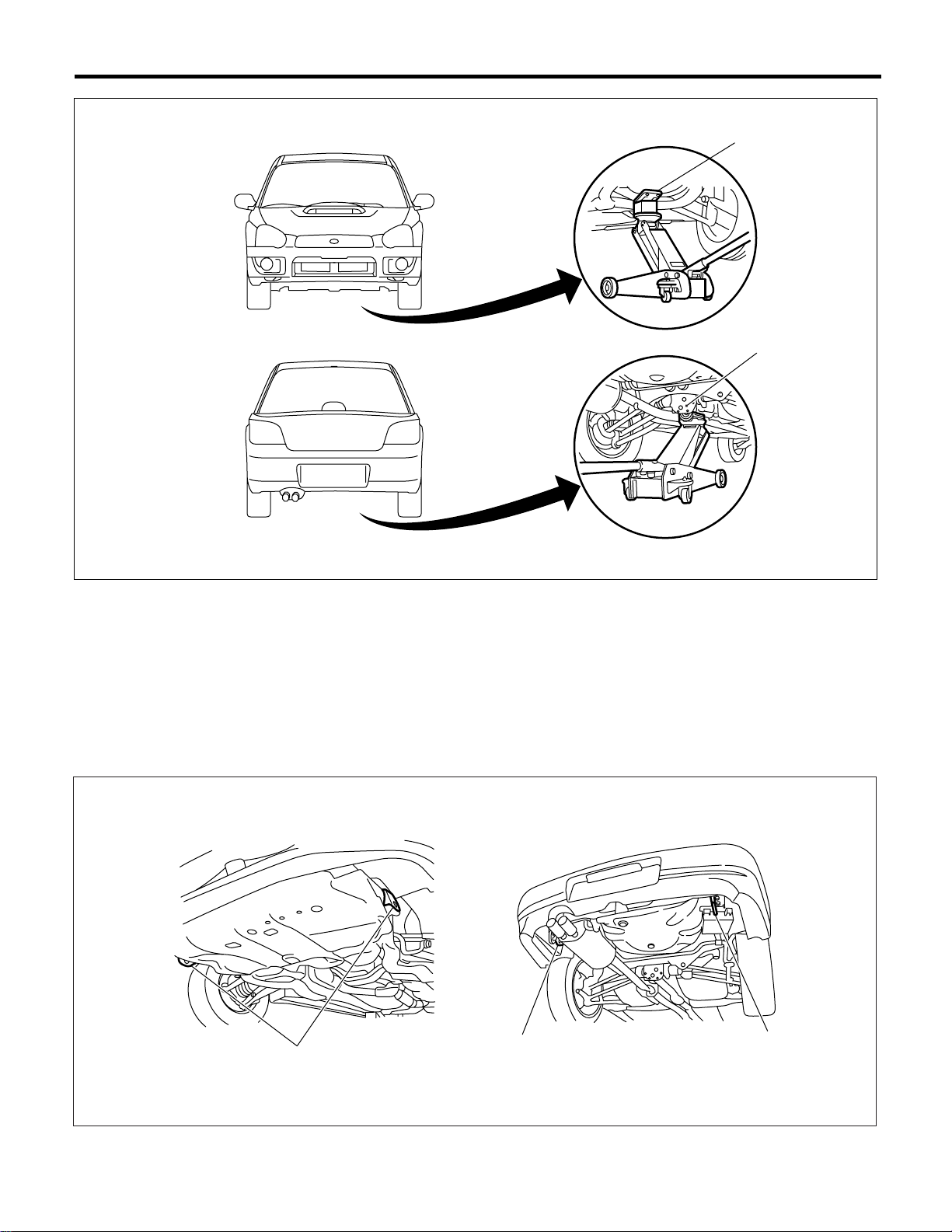
7. LIFTS AND JACKS
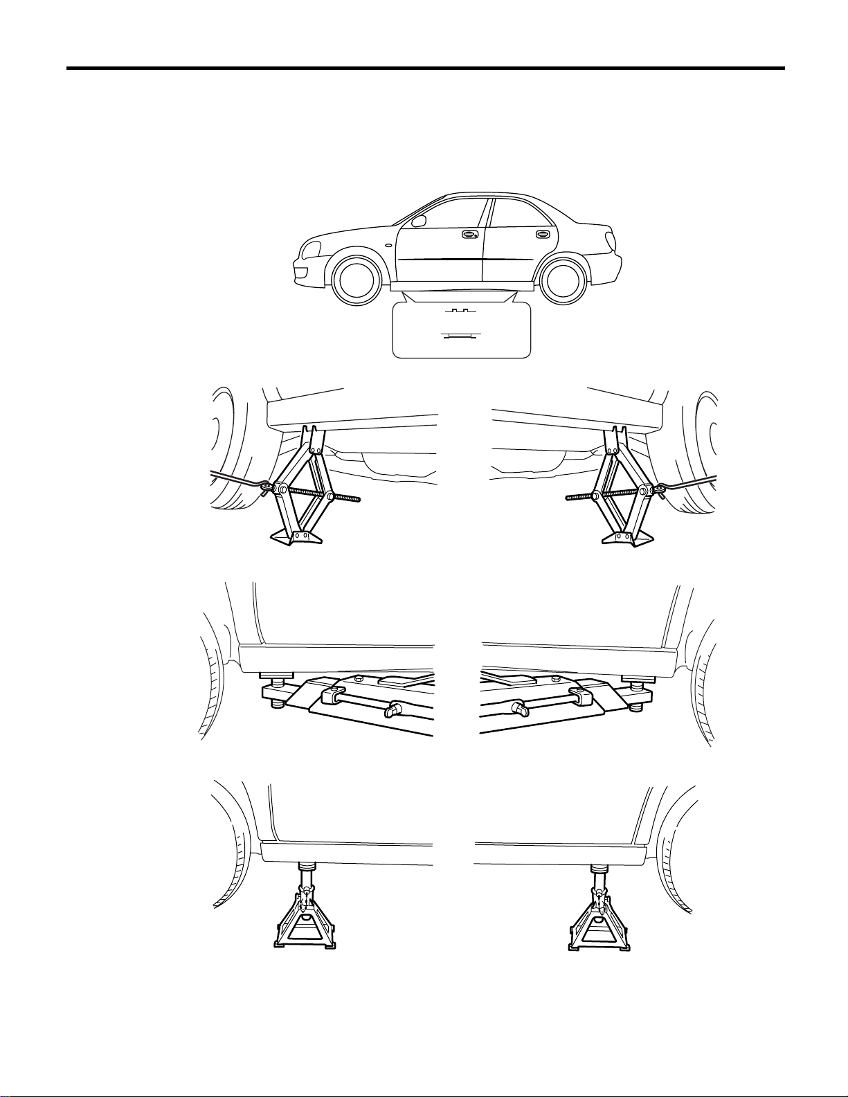
When using a lift or jack to raise a vehicle, always follow instructions concerning jack-up points and weight
limits to prevent the vehicle from falling, which could result in injury. Be especially careful to make sure the
vehicle is balanced before raising it.
Be sure to set the wheel stoppers when jacking-up only the front or rear of the vehicle.
(1)
(5)
(6)
(2)
(3)
(4)
NT-00060
(1) Support locations (3) Lift (5) Without side sill cover
(2) Pantograph jack (4) Rigid rack (6) With side sill cover
NT-3
Page 42
NOTE
Note
(A)
(B)
(1)
(2)
NT-00062
(A) Front (B) Rear
(1) Front crossmember (2) Rear differential
8. TIE-DOWNS
Tie downs are used when transporting vehicles and when using the chassis dynamo. Attach tie downs only
to the specified points on the vehicle.
• Tie-down point
(1)
(1)
(2)
(1) Hook for tie-down (2) Hook for towing and tie-down
NT-4
NT-00063
Page 43
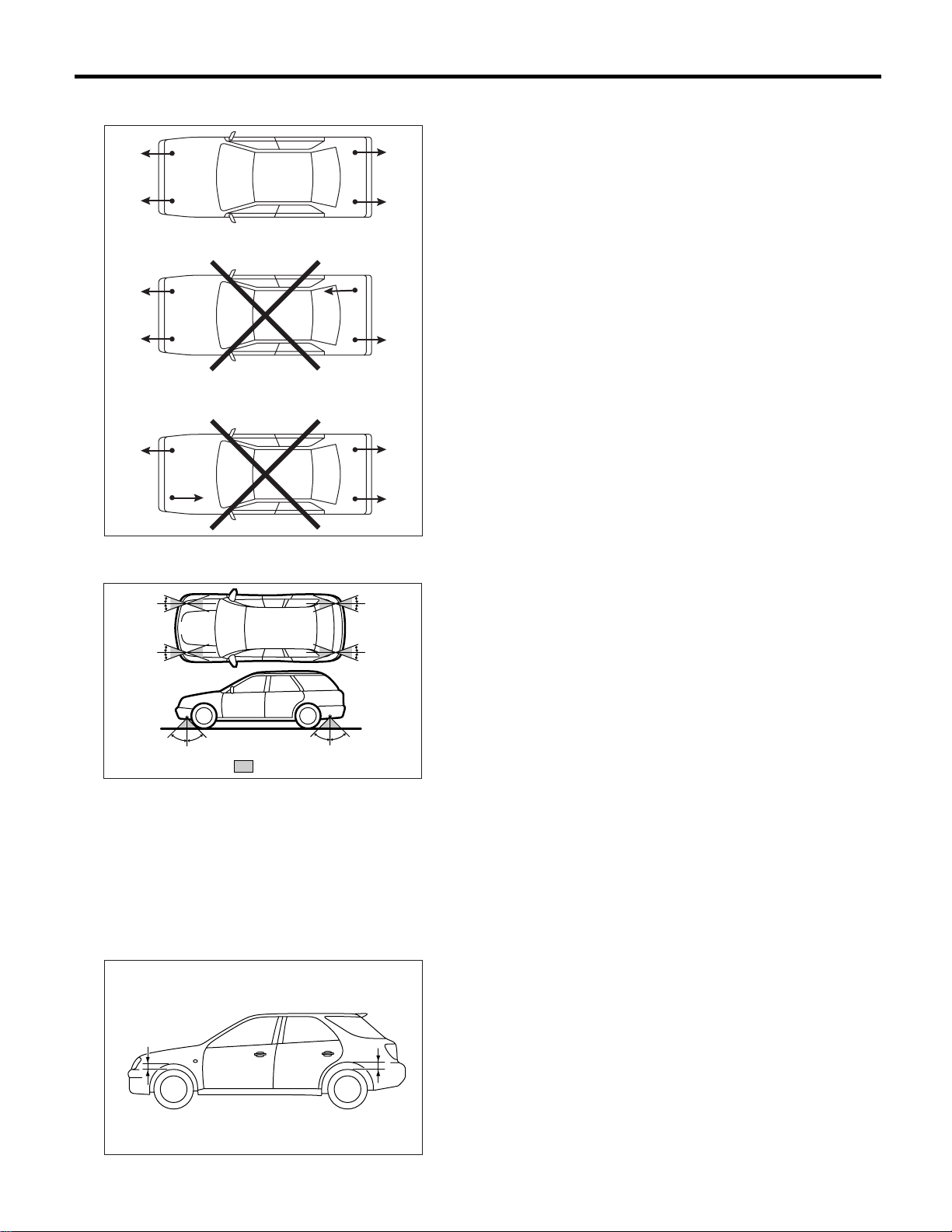
• Chain direction at tie-down condition
Note
NOTE
NT-00038
• Chain pulling range at tie-down condition
20˚
20˚
20˚
20˚
45˚ 45˚
(1) Chain pulling range at tie-down condition
45˚ 45˚
: (1)
20˚
20˚
20˚
20˚
NT-00064
• Vehicle sinking volume at tie-down condition
Measure the distance L between tire highest point
to arch highest point before tie-down and after tiedown. Difference of measurement value (drop
height) shall be within 50.8 mm (1.97 in). Make
sure to fix the vehicle securely.
L
L
NT-00065
NT-5
Page 44
Note
NOTE
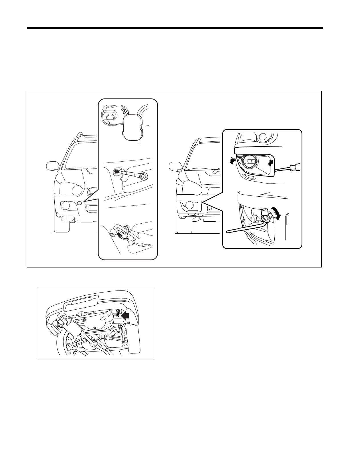
9. TOWING
Avoid towing vehicles except when the vehicle cannot be driven. For models with AWD, AT, or VTD, use a
loader instead of towing. When towing other vehicles, to prevent excessive weight from damaging the hook
or vehicle:
• Do not tow other vehicles with a front hook for tie down.
• Make sure the vehicle towing is heavier that the vehicle being towed.
• Front
• Rear
NT-00066
NT-00067
NT-6
Page 45
Note
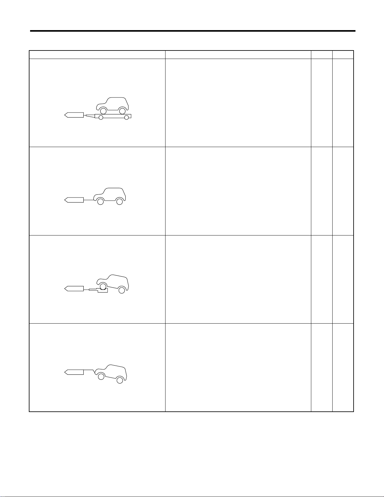
• NOTES
Towing Notes MT AT
Lifting up four wheels (On a trailer) Towing the vehicle after lifting up all four wheels is a
basic rule for AWD model.
NT-00023
Rope • Check if both front and rear wheels are rotated nor-
mally.
• AT model driving conditions: Allow driving speed less
than 30 km/h (19 MPH).
Allow driving distance less than 30 km (19 miles).
NOTE
❍❍
❍▲
NT-00024
Raising the front wheels Prohibited for full-time AWD model. ✕✕
NT-00025
Lifting up the front wheels • Prohibited, due to damage on bumper, front grille, etc.
• Do not raise the vehicle with bumper.
NT-00026
✕✕
Marked ❍: OK, Marked ✕: Prohibited, Marked : Conditionally OK.
NT-7
Page 46
Note
NOTE
CAUTION:
• Check ATF, gear oil and rear differential oil before driving.
• Place the shift lever in “N” position during towing.
• Do not lift up the rear wheels to avoid unsteady rotation.
• Turn the ignition key to “ACC”, then check the steering wheel moves freely.
• Release the parking brake to avoid tire dragging.
• Since the power steering does not work, be careful for the heavy steering effort (When engine is
stopped)
• Since the servo brake does not work, be careful that the brake is not applied effectively. (When engine is stopped)
• In case of the malfunction of internal transmission or drive system, lift up four wheels (on a trailer)
for towing.
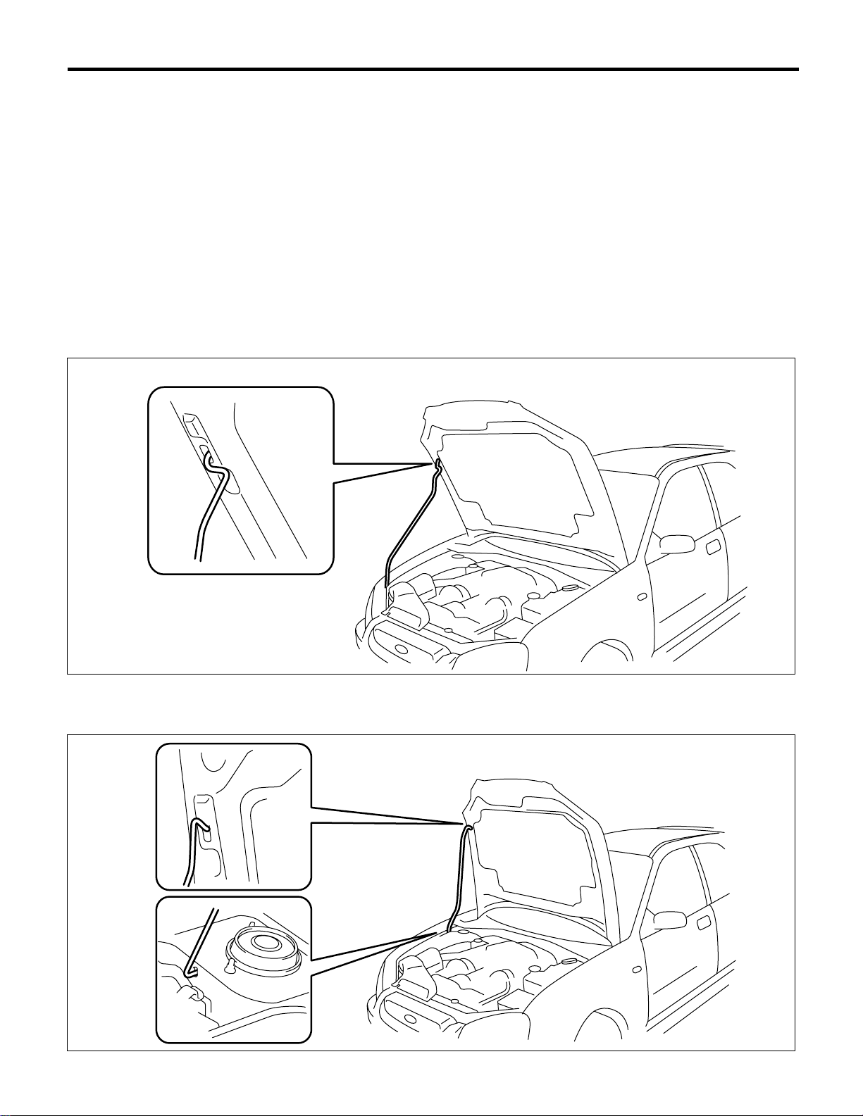
10.FRONT HOOD STAY INSTALLATION
• At the check and general maintenance
• When wider hood opening is necessary
Set stay into the hole of hood inner as shown in the figure below.
NT-00068
NT-00069
NT-8
Page 47

11.TRAINING
For information about training, contact a dealer or
agent.
12.GENERAL SCAN TOOL
Using general scan tools will greatly improve efficiency of repairing engine electronic controls. The
Subaru Select Monitor can be used to diagnose the
engine and also the ABS, the air conditioner, and
other parts.
Note
NOTE
NT-9
Page 48

NOTE
Note
NT-10
Page 49

IDENTIFICATION
1. Identification ................................................................................................2
ID
Page
Page 50
Identification
IDENTIFICATION
1. Identification
A: IDENTIFICATION
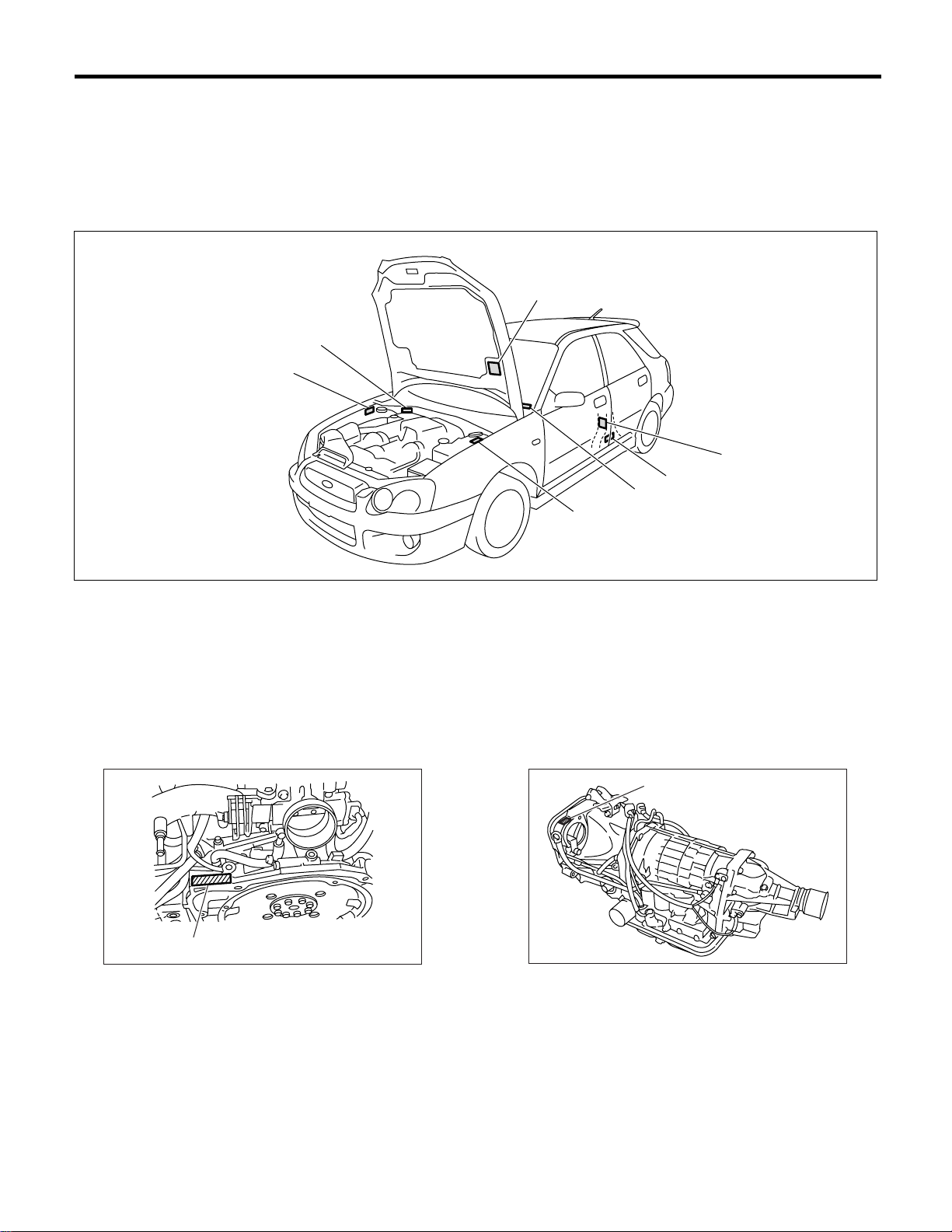
1. IDENTIFICATION NUMBER AND LABEL LOCATIONS
The VIN (Vehicle Identification Numbers) is used to classify the vehicle.
• POSITIONING OF THE PLATE LABEL FOR IDENTIFICATION
(3)
(2)
(1)
(6)
(4)
(5)
(7)
(1) ID plate (Europe model)
ADR compliance plate (Australia
model)
(VIN)
(3) Emission control label
(4)
Tire inflation pressure label (Driver
side) (Australia model)
Tire inflation pressure label (Driver
side) (Except Australia model)
(5) Saudi Arabia plate (Saudi Arabia
model)
Built date plate (Australia model)
(6) Model number plate
(7) Vehicle identification number
(VIN) (Europe RHD model and
Australia turbo model)(2) Vehicle identification number
• ENGINE • AUTOMATIC TRANSMISSION
(1)
(1)
(1) Engine serial number
ID-00053
(1) Transmission serial number
ID-00052
ID-00054
ID-2
Page 51
Identification
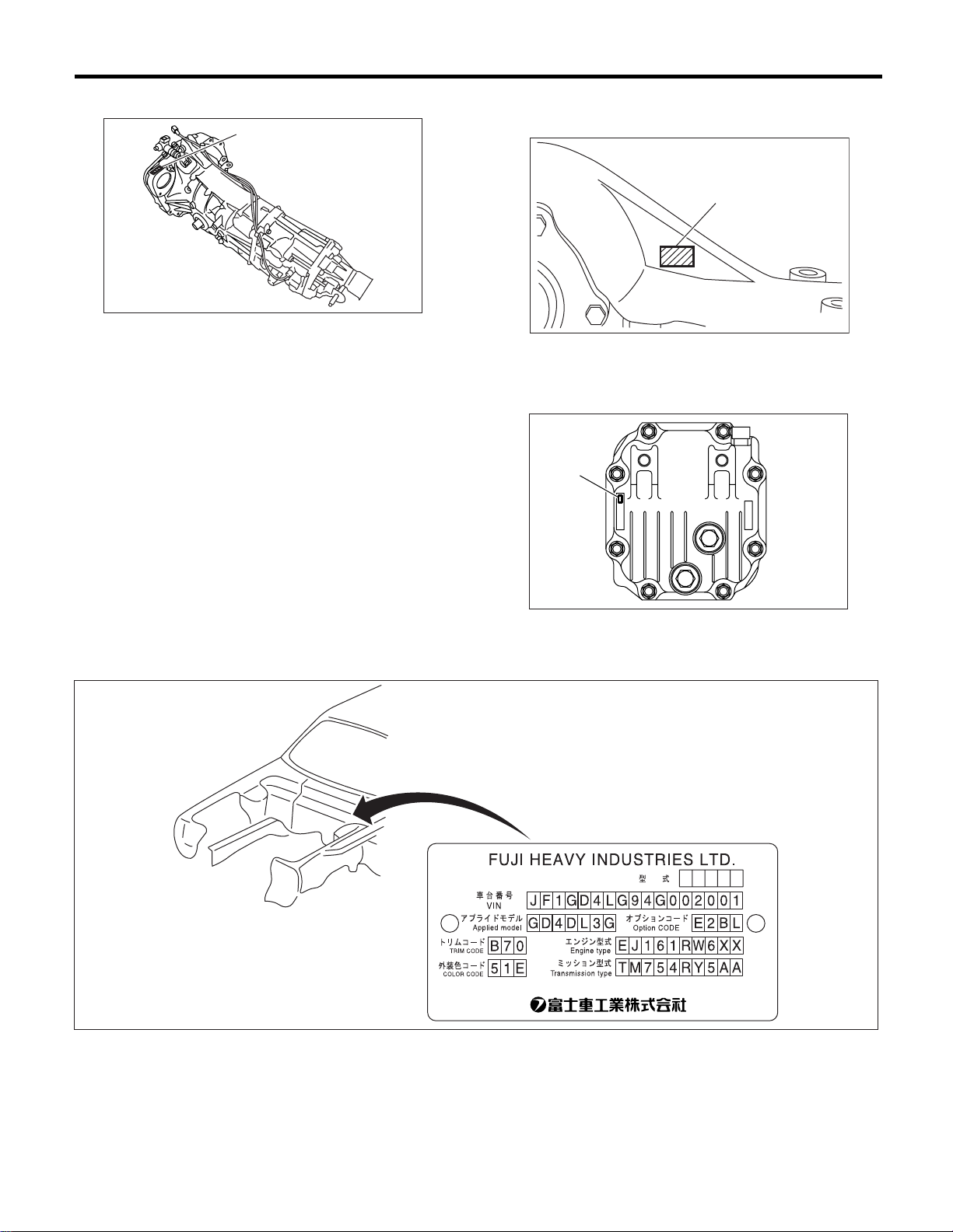
• MANUAL TRANSMISSION • REAR DIFFERENTIAL
(1)
ID-00055
(1) Transmission serial number
• T-type
(1) Type (white paint)
• VA-type
(1)
IDENTIFICATION
(1)
ID-00056
• MODEL NUMBER PLATE
DI-00396
(1) Type (label)
ID-00075
ID-3
Page 52
Identification
IDENTIFICATION
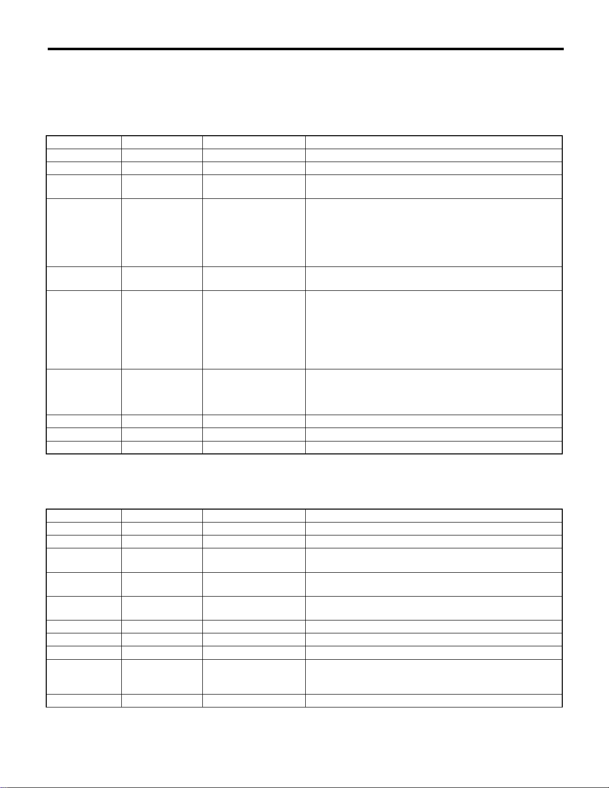
2. MEANING OF V.I.N.
The meaning of the VIN is as follows:
• Europe, Australia and General (Except GCC)
]JF1GD4LG94G002001[
The starting and ending brackets ( ][ ) are stop marks.
Digits Code Meaning Details
1 to 3 JF1 Manufacturer body area JF1: Passenger car, FHI made
4 G Car line IMPREZA
5 D Body type D: 4 Door Sedan
G: Wagon
6 4 Displacement 4: 1.6 L FWD
5: 1.6 L AWD
9: 2.0 L AWD
A: 2.0 L AWD Turbo
B: 2.0 L AWD High power turbo
E: 2.5 L AWD
7 L Steering position K: RHD (Right-hand drive model)
L: LHD (Left-hand drive model)
8 G Engine & transmission G: SOHC MPI 5-speed MT
R: SOHC MPI 4-speed AT
J: SOHC MPI Full-time AWD 5-speed MT
K: SOHC MPI Full-time AWD 5-speed MT Dual range
D: DOHC Turbo Full-time AWD 5-speed MT
H: DOHC Turbo Full-time AWD 6-speed MT
T: DOHC Turbo 4-speed AT Sport Shift
9 9 Drive type 3: Full-time AWD Single range
4: Full-time AWD Dual range
5: AWD AT
9: FWD
10 4 Model year 4: 2004MY
11 G Factory location G: FHI (Gunma)
12 to 17 002001 Serial number —
• GCC countries (Saudi Arabia, etc.)
]JF1GD45MX4G002001[
The starting and ending brackets ( ][ ) are stop marks.
Digits Code Meaning Details
1 to 3 JF1 Manufacturer body area JF1: Passenger car, FHI made
4 G Car line IMPREZA
5 D Body type D: 4 Door Sedan
G: Wagon
6 4 Displacement 4: 1.6 L AWD
8: 2.0 L AWD
75 Grade 5: TS
7: GX
8 M Restraint M: Manual belts, dual airbag
9 X Check digit 0 to 9 & X
10 4 Model year 4: 2004MY
11 G Transmission type G: Full-time AWD 5-speed MT single range
H: Full-time AWD 4-speed AT
J: Full-time AWD 5-speed MT dual range
12 to 17 002001 Serial number —
ID-4
Page 53
Identification
IDENTIFICATION
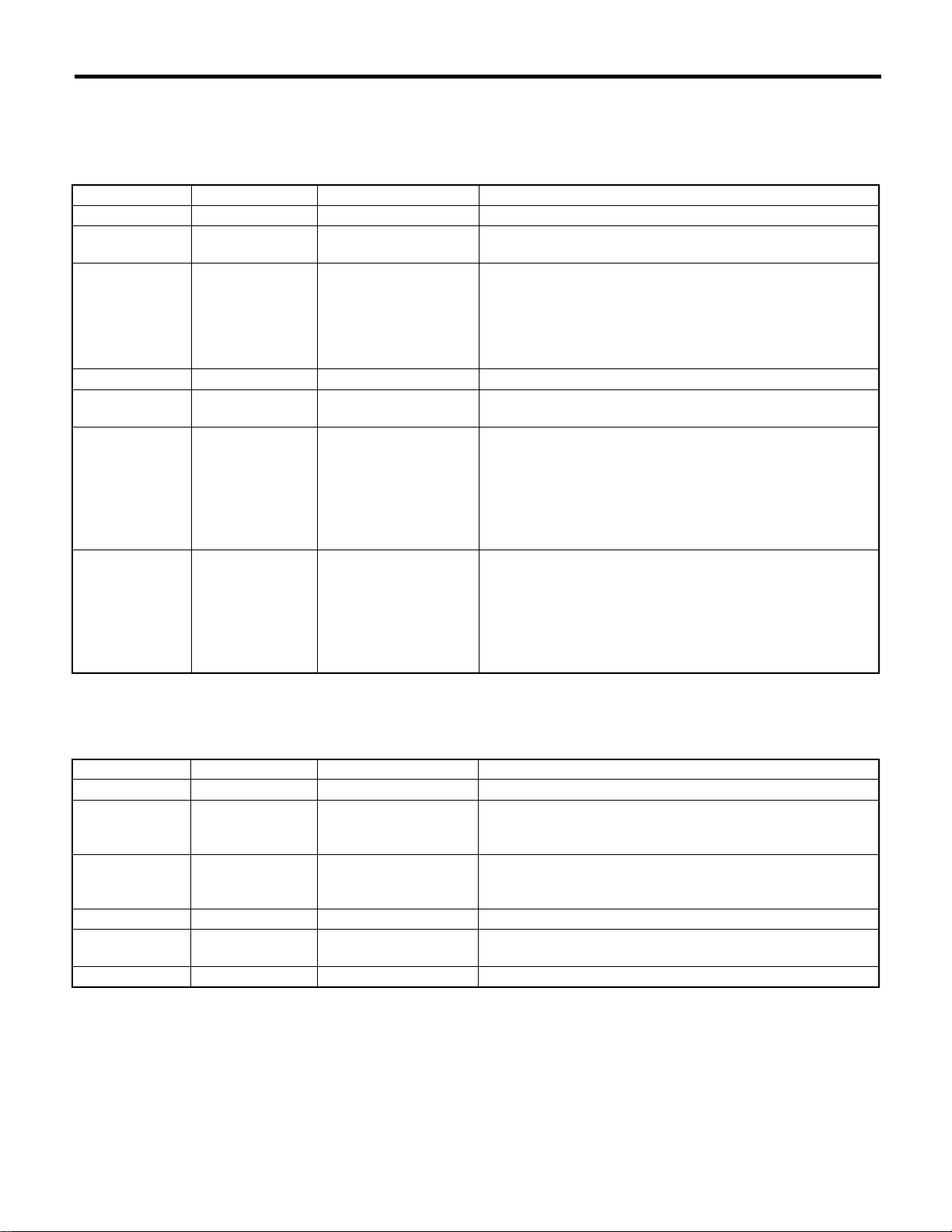
3. MODEL NUMBER PLATE
The model number plate indicates: the applied model, the option code, the trim code, the engine type, the
transmission type, and the exterior color code. This information is helpful when placing orders for parts.
GD9DL5R
Digits Code Meaning Details
1 G Series IMPREZA
2 D Body style D: 4 Door Sedan
G: Wagon
3 9 Engine displacement
Drive system
Suspension system
4 D Model year D: 2004MY
5 L Destination K: Right-hand drive model market
6 5 Grade 3: BASE
7 R Transmission, fuel feed
system
4: 1.6 L FWD
5: 1.6 L AWD
9: 2.0 L AWD
A: 2.0 L AWD Turbo
B: 2.0 L AWD High power turbo
E: 2.5 L AWD
L: Left-hand drive model market
4: TS
5: GX
6: RS
7: OUTBACK
8: WRX
E: STi
K: SOHC MPI Dual range 5-speed MT
G: SOHC MPI 5-speed MT
R: SOHC MPI 4-speed AT
T: DOHC B MPI 4-speed AT Sport Shift
J: SOHC MPI 5-speed MT AWD
D: DOHC B MPI 5-speed MT AWD
H: DOHC B MPI 6-speed MT AWD
The engine and transmission type are as follows:
• Engine
EJ161RW6AA
Digits Code Meaning Details
1 and 2 EJ Engine type EJ: 4 cylinders
3 and 4 16 Displacement 16: 1.6 L
20: 2.0 L
25: 2.5 L
5 1 Fuel feed system 1: D-MPI SOHC-A
5: MPI Turbo
7: MPI High power turbo
6 R Detailed specifications Used when ordering parts. See the parts catalog for details.
7 W Transmission W: MT
X: AT
8 to 10 6AA Detailed specifications Used when ordering parts. See the parts catalog for details.
ID-5
Page 54
Identification
IDENTIFICATION
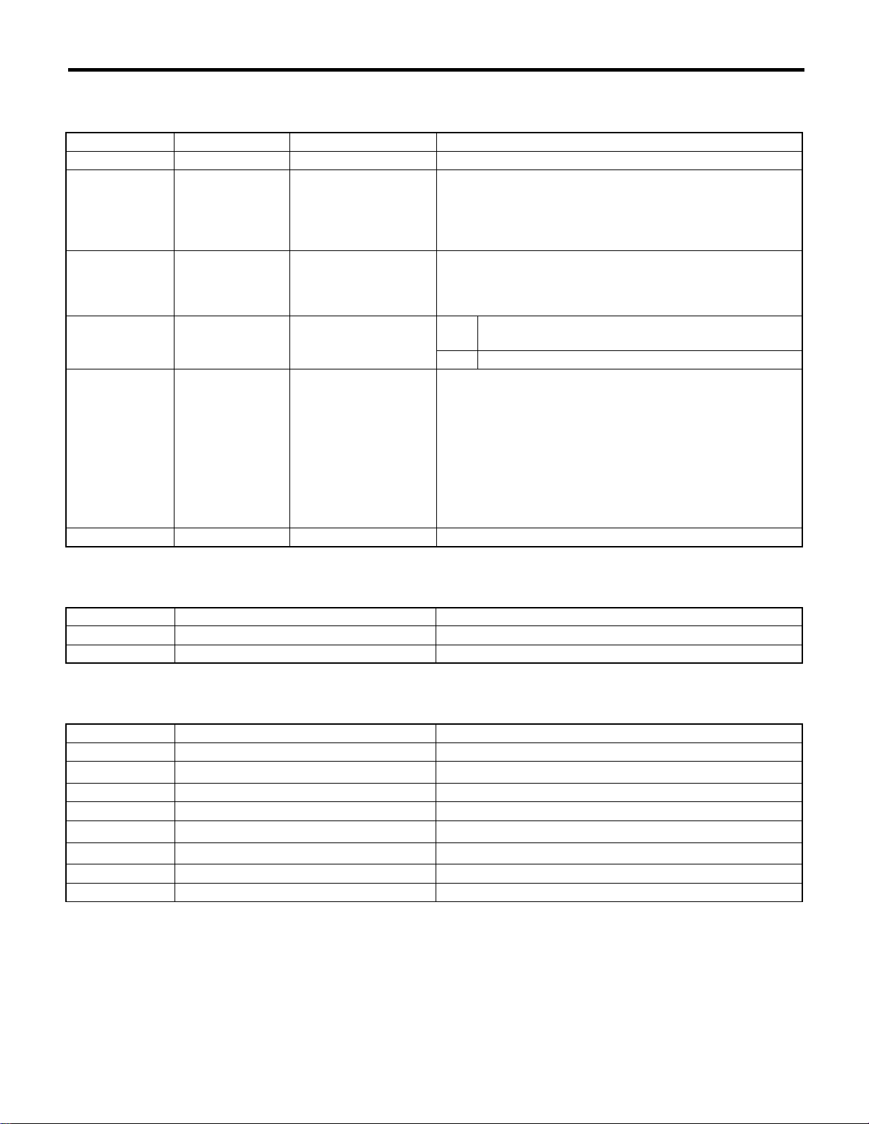
• Transmission
TM754RY5AA
Digits Code Meaning Details
1 T Transmission T: Transmission
2 M Transmission type Y: Full-time AWD MT center differential
V: Full-time AWD AT center differential
Z: Full-time AWD AT MPT
M: FWD MT
A: FWD AT
3 and 4 75 Classification 75: 5MT
85: 6MT
1A: AT
1B: AT
5 4 Series MT 4: 5MT
6: 6MT
AT 4: AT
6 R Transmission specifica-
tions
7 to 10 Y5AA Detailed specifications Used when ordering parts. See the parts catalog for details.
A: FWD 4-speed AT
R: FWD Single Range 5-speed MT
V: Full-time AWD 5-speed MT with viscous coupling center differential single range
W: Full-time AWD 6-speed MT with viscous coupling center differential single range
X: Full-time AWD 5-speed MT with viscous coupling center differential dual range
Z: Full-time AWD 4-speed AT with MPT
Y: Full-time AWD 4-speed AT with VTD
• Rear differential 1
VA-type
Code Reduction gear ratio LSD
XN 4.111 No
XP 4.444 No
• Rear differential 2
T-type
Code Reduction gear ratio LSD
EG 3.900 No
EM 4.444
EJ 4.111 Viscous
EF 3.545 Viscous
HJ 3.545
HG 3.900
HN 3.545 Mechanical
HK 3.900 Mechanical
SURETRAC
SURETRAC
SURETRAC
ID-6
Page 55

Identification
IDENTIFICATION
• Option code
E2BL
Digits Code Meaning Details
1 — 2 E2 Destination EC: Europe model (LHD model)
EK: Europe model (RHD model)
EH: China model
KS: Middle East model
K4: Central and South America model
KA: Australia model
E2: Israel model
K0: General model (LHD model)
K1: General model (RHD model)
Blank: Hong Kong model
3 B Option equipment A: Power window, Power door lock, ABS, Aluminum wheel
B: Power window, Power door lock
C: Power window, Power door lock, Cruise control, ABS, Aluminum wheel
D: Power window, Power door lock, Cruise control, ABS, Front
LSD, Driver’s control center differential
E: Power window, Power door lock, ABS
F: Power window, Power door lock, Cruise control, ABS
L: Power window, Power door lock, ABS, Roof rail, Aluminum
wheel
M: Power window, Power door lock, ABS, Roof rail
N: Power window, Power door lock, Cruise control, ABS, Roof
rail
O: Power window, Power door lock, Cruise control, ABS, Roof
rail, Aluminum wheel
P: Power window, Power door lock, Aluminum wheel
Q: Power window, Power door lock, Aluminum wheel
R: Power window, Power door lock, Roof rail, Aluminum wheel
T: Power window, Power door lock, Cruise control, ABS, Front
LSD
V: Power window, Power door lock, ABS, Front LSD
Y: Power window, Power door lock, ABS, Front LSD, Driver’s
control center differential
6: Special edition model
ID-7
Page 56

Identification
IDENTIFICATION
Digits Code Meaning Details
4 L Option equipment B: A/C, Airbag, Spoiler package
C: A/C, Airbag, Rear spoiler
F: A/C, Airbag, Sunroof
G: A/C, Airbag, Side airbag
I: A/C, Airbag, Audio, Rear spoiler
J: A/C, Airbag, Spoiler package, Rear spoiler
K: Airbag, Side airbag, Audio
L: A/C, Airbag
M: Airbag
O: A/C, Sunroof, Airbag, Side airbag, Leather seat & door trim
decorative woodturning, Audio, Rear spoiler
P: A/C, Sunroof, Airbag, Side airbag, Rear spoiler
Q: A/C, Sunroof, Airbag, Audio, Rear spoiler
R: A/C, Airbag, Rear spoiler
S: A/C, Airbag, Audio
T: A/C, Sunroof, Airbag, Side airbag, Leather seat & door trim
decorative woodturning, Audio
U: A/C, Sunroof, Airbag, Side airbag
V: A/C, Sunroof, Airbag, Side airbag, Leather seat & door trim
decorative woodturning
W: A/C, Sunroof, Airbag, Rear spoiler
Y: A/C, Sunroof, Airbag, Side airbag, Audio
Z: A/C, Sunroof, Airbag, Side airbag, Leather seat & door trim
decorative woodturning, Rear spoiler
1: Special edition model
2: Special edition model
3: Special edition model
ID-8
Page 57

RECOMMENDED MATERIALS
1. Recommended Materials ............................................................................2
RM
Page
Page 58
Recommended Materials
RECOMMENDED MATERIALS
1. Recommended Materials
A: RECOMMENDED MATERIALS
1. GENERAL
To insure the best performance, always use the
specified oil, gasoline, adhesive, sealant, etc. or a
substitute of equivalent quality.
2. FUEL
Always use a gasoline of the same or higher octane
value than specified in the owner’s manual. Ignoring the specifications below will result in damage or
poor operation of the engine and fuel injection system. Use the specified gasoline to correct performance.
• Unleaded gasoline
Use unleaded gasoline and not leaded gasoline on
vehicles with catalytic converter installed to reduce
air pollution. Using leaded gasoline will damage the
catalytic converter.
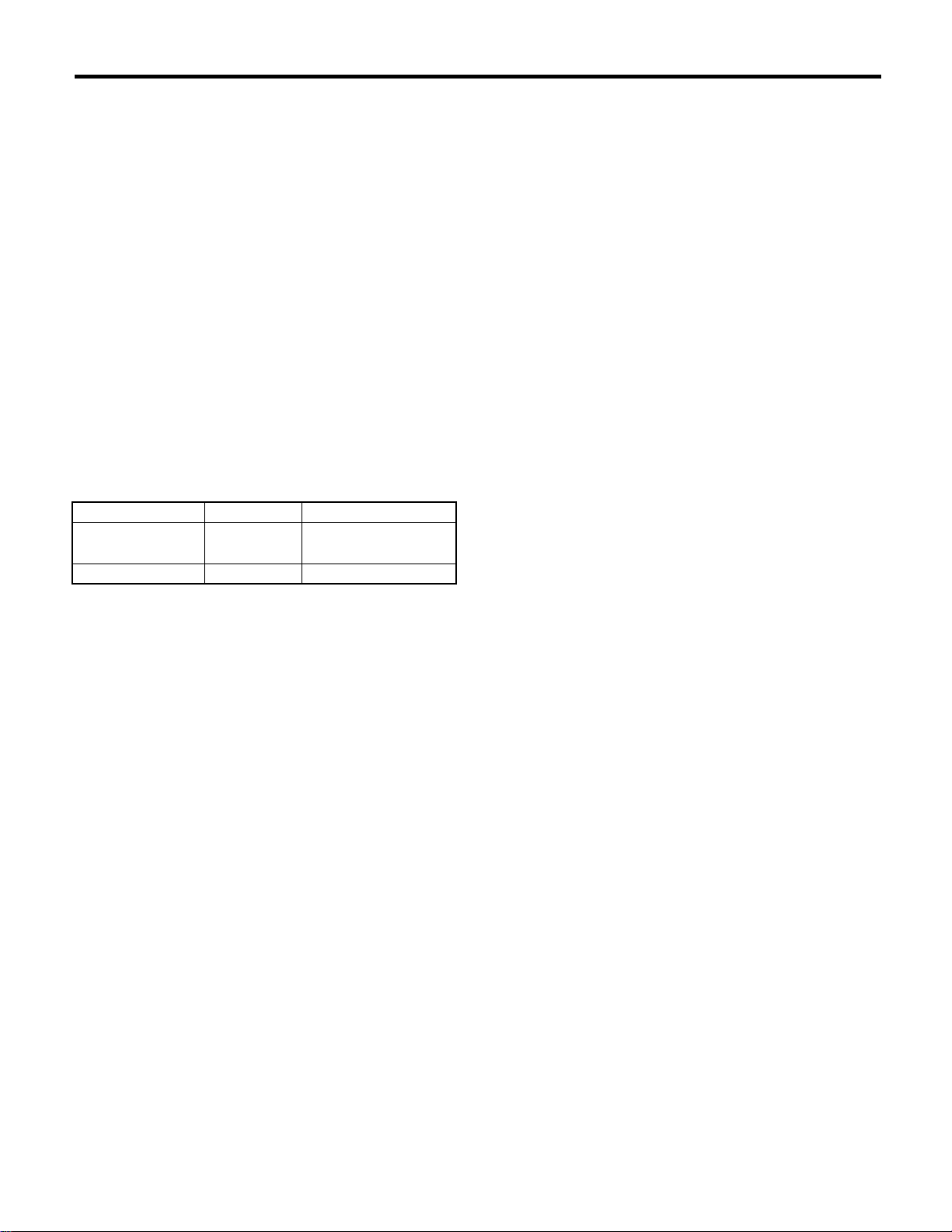
Model Petrol RON
SOHC Unleaded
DOHC turbo Unleaded More than 98 RON
*
: KA, KS model
More than 95 RON
More than 90 RON
*
• Leaded gasoline
On vehicles without catalytic converter, use leaded
gasoline with an octane value of 90 RON or higher.
RM-2
Page 59
Recommended Materials
RECOMMENDED MATERIALS
3. LUBRICANTS
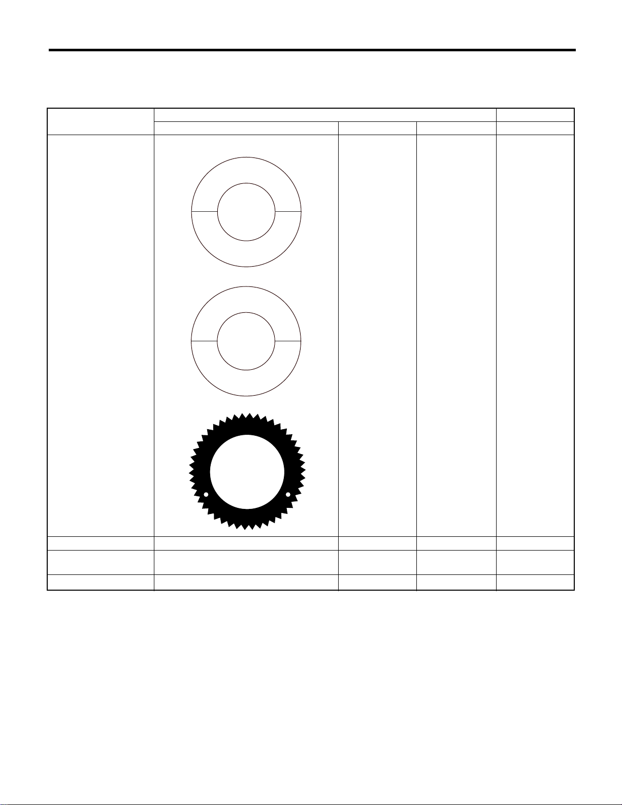
Use either the lubricants in the table below or equivalent lubricants. See the table below to choose the correct
SAE viscosity.
Lubricant Recommended Alternative
API Spec. CCMC Spec. ACEA Spec. API Spec.
Engine oil SL, SJ Grade “Energy conserving”, or SH G4 or G5 A1, A2 or A3 SG, SF
V
R
I
C
E
E
N
E
I
P
A
0W-20
R
G
Y
I
P
A
S
SAE
S
E
S
L
G
N
I
V
R
E
S
C
N
O
RM-00006
V
R
I
C
E
E
S
L
SAE
5W-30
E
N
E
R
G
Y
C
N
O
O
L
R
T
E
P
N
A
FOR
C
I
R
E
GASOLINE
M
A
ENGINES
C
E
R
T
F
I
Manual transmission oil GL-5 ———
AT front differential gear
oil
Rear differential gear oil
★1
: Use LSD oil for model with driver’s control center differential.
GL-5 ———
★1
GL-5
G
N
I
V
R
E
S
RM-00001
E
U
M
I
N
S
T
I
T
U
T
E
D
E
I
RM-00002
———
RM-3
Page 60
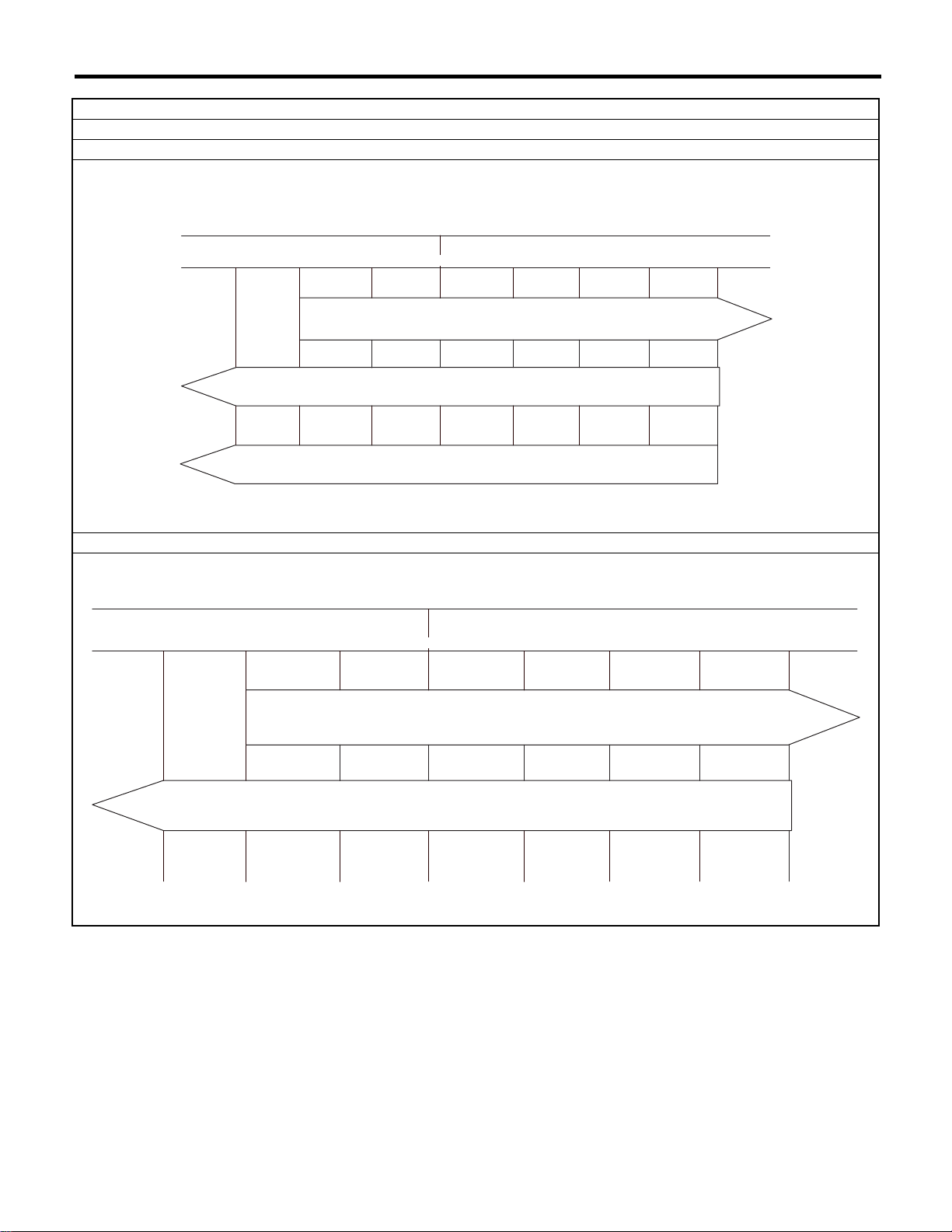
RECOMMENDED MATERIALS
(˚C) –30 –20 –10 0 10 20 30 40
Recommended Materials
SAE viscosity No. and applicable temperature
Engine oil
SOHC model
(˚C)
(˚F)
(˚F) –22 –4 14 50 68 86 104
32
10W-30 or 10W-40
5W-30
0W-20 Recommend
DOHC turbo model
32
0
10 20 30 40
–30
–22
–20 –10
–4 14 50 68 86 104
RM-00007
10W-30 or 10W-40
5W-30 Recommend
RM-00003
RM-4
Page 61
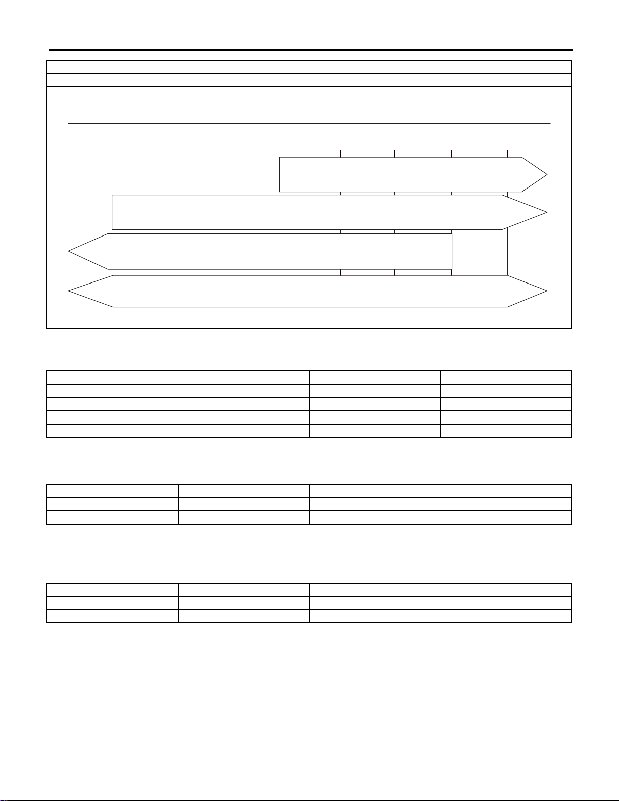
Recommended Materials
RECOMMENDED MATERIALS
SAE viscosity No. and applicable temperature
Manual transmission oil, AT front differential gear oil and rear differential gear oil
32
0
10 20 30 40
(˚F)
(˚C)
–30 –20 –10
–22 –4 14 50 68 86 104
90
85W
80W
75W-90
RM-00004
4. FLUID
Use the fluids specified in the table below. Do not mix two different kinds or makes of fluid.
Fluid Recommended Alternative Remarks
Automatic transmission fluid DEXRON III ——
Power steering fluid DEXRON III ——
Brake fluid FMVSS No. 116 DOT3 ——
Clutch fluid FMVSS No. 116 DOT3 FMVSS No. 116 DOT4 —
5. COOLANT
Use genuine coolant to protect the engine.
Coolant Recommended Item number Alternative
Coolant SUBARU coolant 000016218 None
Water for dilution Distilled water — Tap water (Soft water)
6. REFRIGERANT
Standard air conditioners on Subaru vehicles use HFC134a refrigerant. Do not mix it with other refrigerants.
Also, do not use any compressor oil except for DH-PR.
Air conditioner Recommended Item number Alternative
Refrigerant HFC134a — None
Compressor oil DH-PR — None
RM-5
Page 62
Recommended Materials
RECOMMENDED MATERIALS
7. GREASE
Use the grease and supplementary lubricants shown in the table below.
Grease Application point Recommended Item number Alternative
Supplementary lubricants • O
Grease MT main shaft Clutch grease K0879Y0501 —
sensor
2
• Bolts, etc.
Clutch master cylinder
push rod
• Gear shift lever
• Select lever
• Clutch operating cyl-
inder
• Accelerator pedal
• Clutch pedal
• Brake pedal
• Clutch bearing
• Clutch release lever
• Steering shaft bear-
ing
Steering gear box Valiant grease M-2 003608001 —
• Disc brake
• Drum brake wheel
cylinder
• Drum brake
• Brake shoe
Brake pad Molykote AS-880N K0777YA010 —
Front axle PTJ NSG301 28395AG020 —
• Front axle EBJ
• Front axle BJ
• Rear axle EBJ
• Rear axle BJ
• Front axle DOJ
• Rear axle DOJ
Throttle cable end Silicolube G-30M 004404002 —
Spray type lubricant ——
Silicolube G-40M 004404003 —
SUNLIGHT2 003602010 —
Niglube RX-2 K0779GA102 —
Molykote No. 7439 003602001 —
NTG2218-M 28395FE010 —
NKG205 28395FE020 —
8. ADHESIVES
Use the adhesives shown in the table below, or equivalent.
Adhesive Application point Recommended Item number Alternative
Adhesive Windshield, rear window
glass, rear quarter glass
and body
Inner rearview mirror
base
Soft vinyl Cemedine 540 — 3M’s EC-776, EC-847 or EC-1022
Momentary sealant Cemedine 3000 — Armstrong’s Eastman 910
Dow Automotive’s
Adhesive: Gurit-ESSEX
Betaseal 1502 or equivalent
Glass primer: Betawipe VP
04604, Betaprime 5001
Paint surface primer: Betaprime 5402
REPAIR KIT IN MR 65029FC000 —
——
(Spray type)
RM-6
Page 63
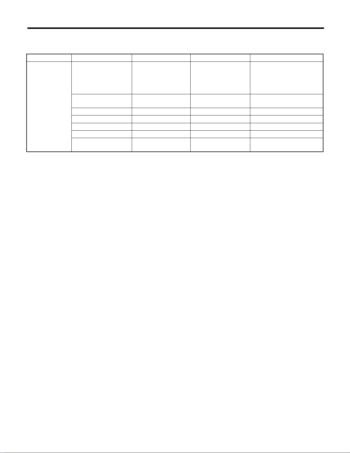
Recommended Materials
RECOMMENDED MATERIALS
9. SEAL MATERIAL
Use seal material shown in the table below, or equivalent.
Seal material Application point Recommended Item number Alternative
Seal material • Cylinder block
• Torque converter
clutch case
• Transmission oil pan
(6MT model)
Transmission oil pan (AT
model)
Rear differential Three Bond 1324 004403042 —
Rear differential Three Bond 1105 004403010 Dow Corning’s No. 7038
Steering adjusting screw Three Bond 1141 004403006 —
Camshaft cap Three Bond 1280B K0877YA018 —
• Front sealing cover
• Rear sealing cover
Three Bond 1215B 004403007 Dow Corning’s No. 7038
Three Bond 1217B K0877YA020 —
3M Butyl tape 8626 ——
RM-7
Page 64

RECOMMENDED MATERIALS
Recommended Materials
RM-8
Page 65

PRE-DELIVERY INSPECTION
1. Pre-delivery Inspection................................................................................2
PI
Page
Page 66
Pre-delivery Inspection
PRE-DELIVERY INSPECTION
1. Pre-delivery Inspection
A: GENERAL DESCRIPTION
The purposes of the pre-delivery inspection (PDI) are as follows.
• Remove the additional parts used for ensuring the vehicle quality during transportation and restore the vehicle to its normal state.
• Check if the vehicle before delivery is in a normal state.
• Check for any damage to the vehicle or parts that may have taken place during transportation or storage.
• Check if the vehicle after repair is in a normal state.
• Make sure to provide a complete vehicle to the customer.
For the above reasons, all SUBARU dealers (dealerships) carry out the PDIs before delivering a vehicle.
B: PRE-DELIVERY INSPECTION (PDI) PROCEDURE
STATIC CHECKS JUST AFTER VEHICLE RECEIPT
PROCEDURE Check point
1. Appearance check (1) If the vehicle is covered with protective coating, visually check the vehicle
body for damage and dents. If the protective coating has been removed,
visually check the body paints for damage or stains in detail.
(2) Visually check the glass and light lenses for any damage, cracks or
excessive gaps to the body sheet metal.
(3) Visually check the plated parts for any damage.
2. Tire check (1) Check the tires for damage, abnormal conditions, and dents on the
wheels.
(2) Check the tire air pressure.
3. Fuse installation If the vehicle is about to be delivered to the customer, attach a back-up fuse.
If the vehicle is about to be delivered to the customer, connect air conditioner
4. Air conditioner harness connection
5. Check the doors for lock/unlock and open/close
operations.
6. Double lock operation check Check the double lock for normal operations.
7. Check the operation of child safety lock system Check that the child safety lock system operates normally.
8. Check the trunk lid for open/close operations. (1) Operate the trunk lock release lever to check that the trunk opens nor-
9. Check the rear gate for lock/unlock and open/
close operations.
10. Operation check of fuel lid opener lock release
lever
11. Accessory check Check that the following accessories are provided.
12. Operation check of front hood lock release
system
13. Battery Check the battery terminals for any abnormal conditions such as rust and
14. Brake fluid Check that the fluid level is normal.
15. Engine oil Check that the oil level is normal.
16. Transmission gear oil Check that the transmission gear oil level is normal.
harness.
(1) Using the key, check if the trunk lid can be locked or unlocked normally.
(2) Open and close all doors to see that there are no abnormal conditions.
(3) Operate the power door lock switch to check that the door (rear gate) is
locked and unlocked normally.
mally.
(2) Open and close the trunk lid to see that there are no abnormal conditions.
(1) Check if the rear gate can be unlocked normally through the emergency
hole.
(2) Open and close the rear gate to see that there are no abnormal conditions.
Operate the fuel lid opener to check that the fuel lid is unlocked normally.
• Owner’s manual
• Warranty booklet
• Maintenance note
• Spare key
• Jack
• Tool set
• Spare tire
Operate the front hood lock release lever to check that the front hood is
unlocked normally.
trace of battery fluid leaks.
PI-2
Page 67
Pre-delivery Inspection
PRE-DELIVERY INSPECTION
PROCEDURE Check point
17. AT front differential oil Check that the AT front differential oil level is normal.
18. Engine coolant Check that the engine coolant level is normal.
19. Clutch fluid Check that the clutch fluid level is normal.
20. Window washer fluid Check that the window washer fluid level is normal.
21. Front hood latch check Check that the hood is closed and latched securely.
22. Keyless entry system Check that the keyless entry system operates normally.
23. Seat (1) Check the seat surfaces for stain or dirt.
(2) Check the seat installation conditions and functionality.
24. Seat belt Check the seat belt installation conditions and functionality.
25. Wheel alignment Check that the wheel alignments are properly adjusted.
CHECKS WITH ENGINE RUNNING
PROCEDURE Check point
26. Test mode connector Test mode connectors
27. Immobilizer system (1) Check that the engine starts with all keys that are equipped on vehicle.
(2) 60 seconds after turning ignition switch from ON to ACC or OFF, or immediately after removing key, check that the security indicator light blinking.
28. Starting condition Start the engine and check that the engine starts smoothly.
29. Exhaust system Check that the exhaust noise is normal and no leaks are found.
30. Indicator and warning lights Check that all the indicator and warning lights are gone out.
31. Clock Check that the clock operates normally.
32. Audio Check the radio, CD and MD player for normal operation.
33. Front accessory power supply socket Check that the front accessory power socket operates normally.
34. Lighting system Check that the lighting system operates normally.
35. Window washer Check that the window washer system operates normally.
36. Wiper Check that the wiper system operates normally.
37. Power window operation check Check the power window for normal operations.
38. Sunroof Check that the sunroof operates normally.
39. Door mirror Check that the remote control mirror operates normally.
DYNAMIC TEST WITH VEHICLE RUNNING
PROCEDURE Check point
40. Brake test Check the foot brake for normal operations.
41. Parking brake Check the parking brake for normal operations.
42. AT shift control Check that the AT shift patterns are correct.
43. Heater & ventilation Check that the heater & ventilation system operates normally.
44. Air conditioner Check that the air conditioner operates normally.
45. Cruise control Check that the cruise control system operates normally.
CHECKS AFTER DYNAMIC TEST
PROCEDURE Check point
46. ATF level Check that the ATF level is correct.
47. Power steering fluid level Check that the power steering fluid level is normal.
48. Fluid leak check Check for fluid/oil leaks.
49. Water leak test Spray the vehicle with water and check for water leaks.
50. Appearance check 2 (1) Remove the protective coating (if any).
(2) Check the body paints for damage and stain.
(3) Check the plated parts for damage and rust.
PI-3
Page 68
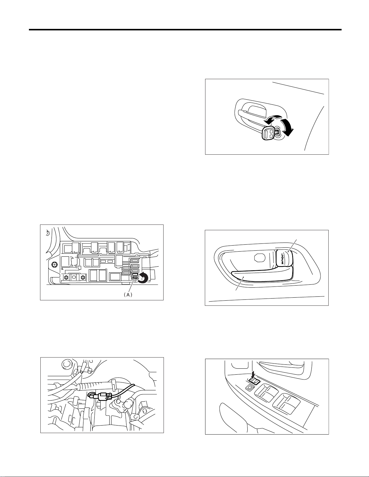
PRE-DELIVERY INSPECTION
Pre-delivery Inspection
1. APPEARANCE CHECK
• If the vehicle is covered with protective coating,
visually check the vehicle body for damage and
dents.
• If there is no protective coating, check the body
paints for small areas of damage or stains and repair as necessary.
• Check the window glass, door glass, and lights
for any cracks or damage and repair or replace the
parts as necessary.
• Check the plated parts, such as the grilles and
door knobs, for damage or loss of gloss and repair
or replace the parts as necessary.
2. TIRE CHECK
• Check the tires for damage, abnormal conditions, and dents on the wheels.
• Check the tire size, spare tire and tire air pressure described on the tire air pressure label (driver’s side).
3. FUSE INSTALLATION
A vehicle just delivered has no fuse for the back-up
circuit to prevent battery discharge. Attach a 15 A
fuse (A) as shown in the figure.
5. CHECK THE DOORS FOR LOCK/UNLOCK AND OPEN/CLOSE OPERATIONS
1) Using the key, lock and unlock the door several
times to check for normal operation. Open and
close the door several times for smooth movement.
(A)
(B)
PI-00140
(A) Unlock
(B) Lock
2) Close the driver’s door completely, and place the
door lock knob (A) to the lock position. Then pull inner remotes (B) to ensure that doors will not open.
For other doors, place the door lock knob (A) to the
lock positions and then pull the inner remote to ensure that the doors will not open.
PI-00001
4. CONNECTION OF AIR CONDITIONER
HARNESS
A vehicle just delivered has its air conditioner harness disconnected to protect the air conditioner
compressor. Connect the harness as shown in the
figure.
(A)
(B)
PI-00004
(A) Door lock knob
(B) Inner remote
3) Press the driver’s side power door lock switch to
lock side. Check that all doors including rear gate
are locked.
PI-00139
PI-00142
PI-4
Page 69
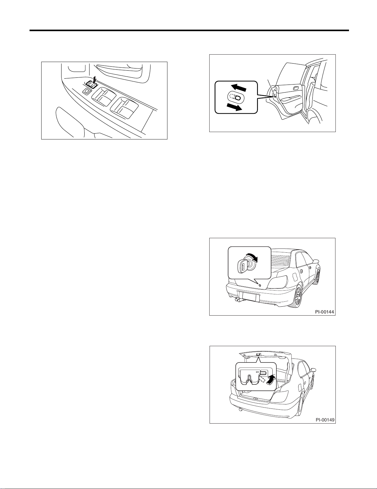
Pre-delivery Inspection
PRE-DELIVERY INSPECTION
4) Press the driver’s side power door lock switch to
unlock side. Check that all doors including rear
gate are unlocked.
PI-00143
6. CHECK DOUBLE LOCK OPERATION
1) Fully open all the windows.
2) Remove the key.
3) Lock all the doors using the door key cylinder or
transmitter.
4) Verify that all the doors including rear gate are
not unlocked when pressing power door lock switch
to unlock side.
5) Verify that the door is not opened when operating door lock knob to unlock position and pulling inner remote. Perform the same check for other
doors.
6) Check that all the doors are unlocked when door
is unlocked using door key cylinder or transmitter,
or ignition switch is turned to ON.
4) Next, pull the outside door handles of the rear
doors to ensure that the doors will open.
(C)
(A)
(B)
PI-00084
(A) Unlock
(B) Lock
(C) Child safety lock
8. CHECK THE TRUNK LID FOR OPEN/
CLOSE OPERATIONS
1) Operate the trunk lock release lever and verify
that the trunk lid opens.
2) Using the key, open the trunk lid several times to
check for normal operation.
3) Open and close the trunk lid several times for
smooth movement.
7. CHECK THE OPERATION OF CHILD
SAFETY LOCKS
1) Set the child safety lock on both rear doors to the
lock positions.
2) Close the rear doors completely.
3) Check that the lock levers of the rear doors are in
the unlock positions. Then, pull the inner remotes
of the rear doors to ensure that the doors will not
open.
PI-00144
4) Set the trunk lid release lever to the cancel position, and check that the trunk lid can only be
opened with the key.
PI-00149
PI-5
Page 70
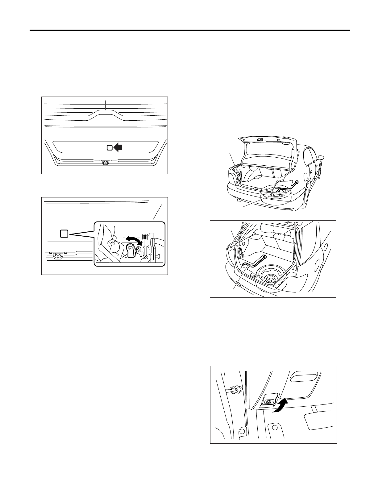
PRE-DELIVERY INSPECTION
Pre-delivery Inspection
9. CHECK THE REAR GATE FOR LOCK/
UNLOCK AND OPEN/CLOSE OPERATIONS
1) Open and close the rear gate several times for
smooth movement.
2) Operate the rear gate lever to check that the rear
gate is locked and unlocked normally.
(1) Remove the blind cover inside the rear gate.
PI-00147
(2) Check that the rear gate is locked correctly
when lever is operated using a finger.
11.ACCESSORY CHECK
Check that the following accessories are provided
in the luggage compartment or cargo area.
• Owner’s manual
• Warranty booklet
• Service booklet
• Spare key
• Jack
• Tool set
• Spare tire
• Immobilizer cover (EK model)
• Immobilizer relay (EK model)
(A)
(B)
PI-00145
PI-00148
10.OPERATION CHECK OF FUEL LID
OPENER LOCK RELEASE LEVER
Operate the fuel lid opener and verify that the fuel
lid opens normally. Check that the filler cap is securely closed.
(A)
(B)
(A) Jack
(B) Jack handle
PI-00146
12.OPERATION CHECK OF HOOD LOCK
RELEASE SYSTEM
Operate the hood release knob (A) and check that
the hood is unlocked normally.
PI-6
PI-00071
Page 71
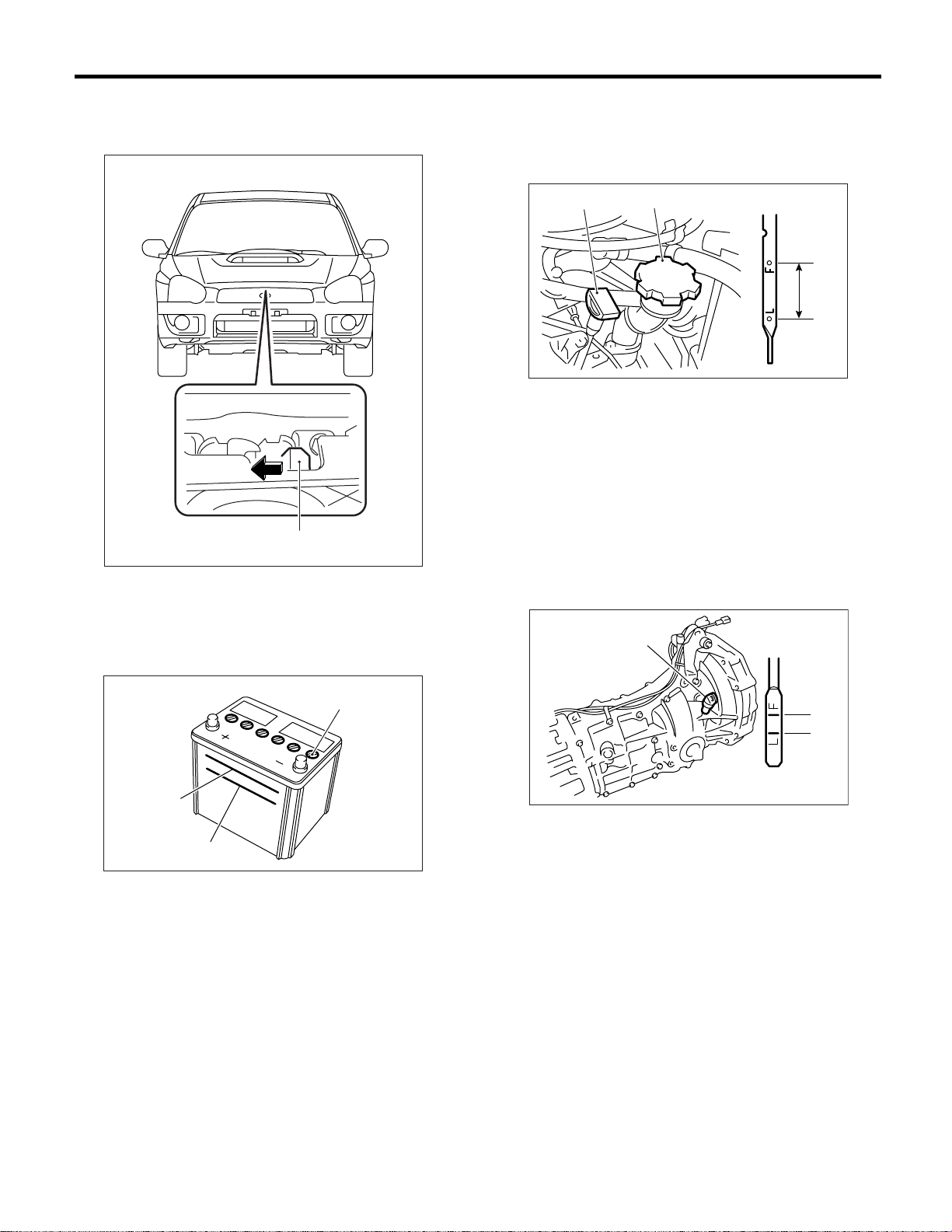
Pre-delivery Inspection
PRE-DELIVERY INSPECTION
Operate the lever (A) and check that the hood is
opened normally. Then support the hood with hood
stay.
(A)
PI-00151
13.BATTERY
15.ENGINE OIL
Check the engine oil amount. If the amount is insufficient, check that no leaks are found. Then, add
the necessary amount of the specified engine oil.
(A)
(A) Oil level gauge
(B) Engine oil filler cap
(C) Upper level
(D) Lower level
(E) Approx. 1.0 2 (1.1 US qt, 0.9 Imp qt)
(B)
(C)
(E)
(D)
LU-00138
16.TRANSMISSION FLUID
Check the transmission fluid amount. If the amount
is insufficient, check that no leaks are found. Then,
add the necessary amount of the specified fluid.
Check the battery terminals to make sure that no
rust or corrosions due to fluid leaks are found.
Check that the battery caps are securely tightened.
(A)
(B)
(C)
PI-00012
(A) Cap
(B) Upper level
(C) Lower level
14.BRAKE FLUID
Check the brake fluid amount. If the amount is insufficient, carry out a brake line test to identify
brake fluid leaks and check the brake operation. After that, refill the brake fluid tank with the specified
type of fluid.
(A)
(B)
(C)
PM-00030
(A) Oil level gauge
(B) Upper level
(C) Lower level
PI-7
Page 72
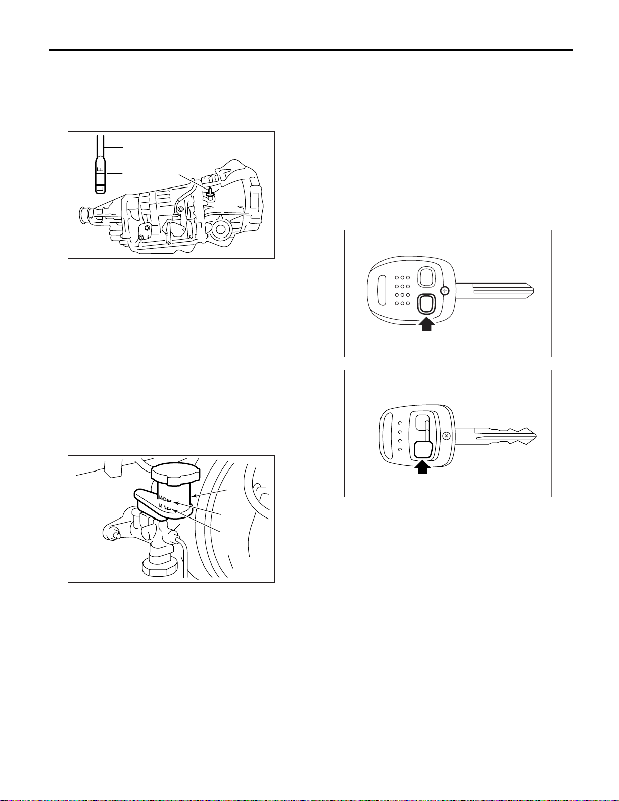
PRE-DELIVERY INSPECTION
Pre-delivery Inspection
17.AT FRONT DIFFERENTIAL OIL
Check the AT front differential oil amount. If the
amount is insufficient, check that no leaks are
found. Then, add the necessary amount of the
specified AT front differential oil.
(A)
(B)
(C)
(A) Oil level gauge
(B) Upper level
(C) Lower level
(A)
PI-00183
18.COOLANT
Check the coolant amount on the reservoir. If the
amount is insufficient, check that no leaks are
found. Then, add the necessary amount of coolant
with the specified concentration.
21.HOOD LATCH CHECK
Retract the hood stay and close the hood. Check
that the hood is securely latched.
22.KEYLESS ENTRY SYSTEM
Check the keyless entry system operations as follows.
• Remove the key from the ignition switch and
close all the doors including rear gate (wagon model).
• Press the “LOCK” button on the transmitter momentarily once and check that all the doors are
locked and the hazard light flashes once.
PI-00108
19.CLUTCH FLUID
Check the clutch fluid amount. If the amount is insufficient, check that no leaks are found. Then, add
the necessary amount of the specified fluid.
(A)
(C)
(B)
PM-00076
(A) Reservoir tank
(B) MIN level
(C) MAX level
20.WINDOW WASHER FLUID
Check the window washer fluid amount. If the
amount is insufficient, check that no leaks are
found. Then, add the necessary amount of washer
fluid commercially available.
PI-00109
• Press the “OPEN” button on the transmitter momentarily once and check that all doors are unlocked, the hazard light flashes twice and the
interior light illuminates.
• Close all doors and rear gate, press the “LOCK”
button of the transmitter. Press the “OPEN” button
of the transmitter and wait for 30 seconds. Check
that all doors and the rear gate are automatically
locked again.
23.SEAT
Check that each seat provides full functionality in
sliding and reclining. Check all available functions
of the rear seat such as a trunk-through center arm
rest.
24.SEAT BELT
Pull out the seat belt and then release it. Check that
the belt webbing retracts smoothly.
PI-8
Page 73
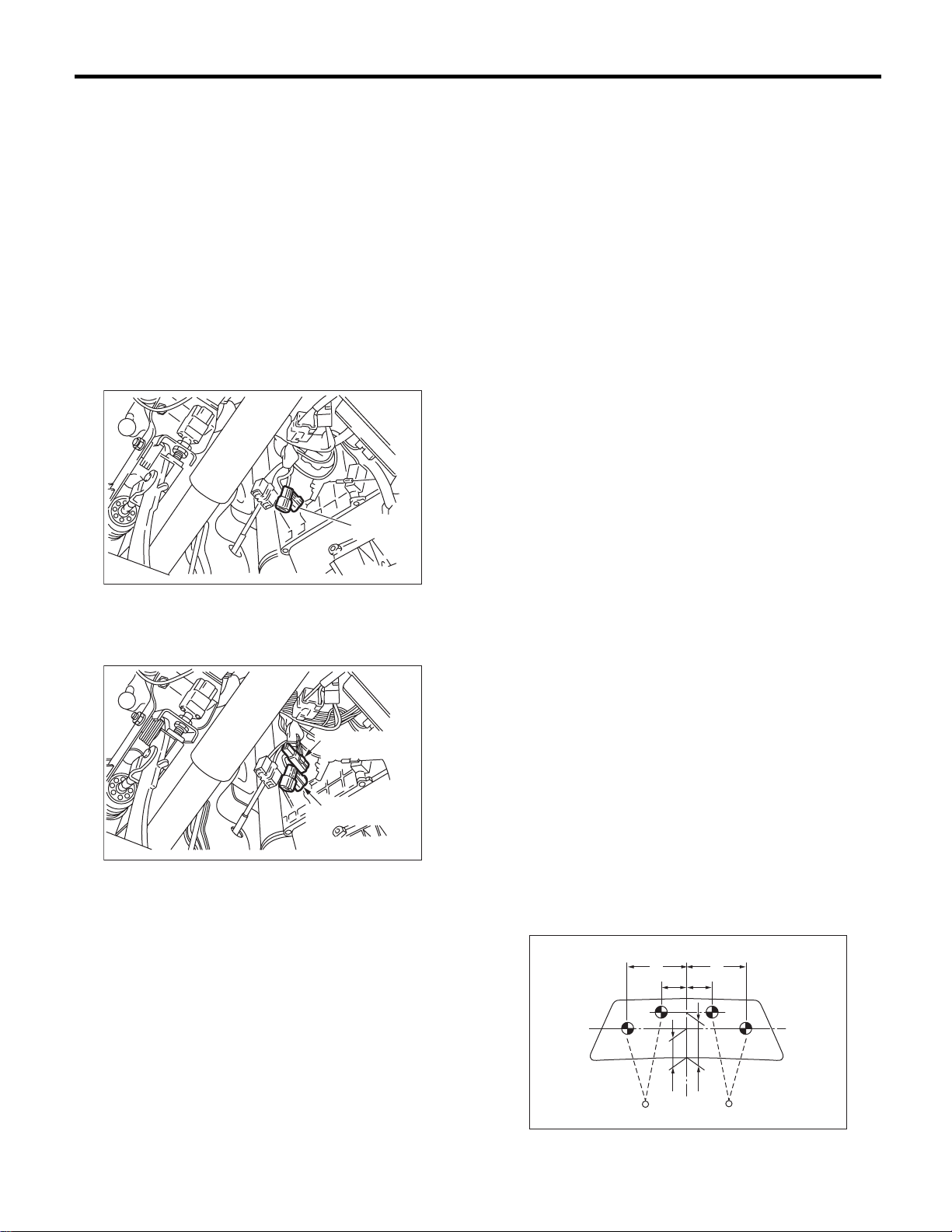
Pre-delivery Inspection
PRE-DELIVERY INSPECTION
25.WHEEL ALIGNMENT
Check the wheel alignments. <Ref. to FS-6, Wheel
Alignment.> and <Ref. to RS-10, Wheel Alignment.>
26.TEST MODE CONNECTOR
Turn the ignition switch to ON and check that the
malfunction indicator light starts blinking. If the light
blinks, return the ignition key to LOCK and disconnect the test mode connector. Then, turn the ignition key to ON again. If the malfunction indicator
light blinks at that time in spite of the disconnected
test mode connector, carry out an engine diagnosis.
• With OBD MODEL
( A )
PI-00119
(A) Test mode connector (Green)
28.STARTING CONDITION
Start the engine and check that the engine starts
smoothly. If any battery voltage problems are
found, recharge or replace the battery. If any abnormal noises are observed, immediately stop the
engine and check and repair the necessary components.
29.EXHAUST SYSTEM
Listen to the exhaust noise to see if no abnormal
noises are observed.
30.INDICATOR LIGHT
Check that all the indicator lights are off.
31.CLOCK
Check the clock for normal operations and enough
accuracy.
32.AUDIO
Check if the radio for functions fully, speaker emitts
sound normally and noise level is normal. Also
check the CD, MD unit operations.
33.FRONT ACCESSORY POWER SUPPLY
SOCKET
Check the front accessory power supply socket operations.
• Without OBD MODEL
( B )
( A )
PI-00120
(A) Read memory connector (Black)
(B) Test mode connector (Green)
27.IMMOBILIZER SYSTEM
1) Check that the engine starts with all keys that
are equipped on vehicle.
2) 60 seconds after turning the ignition switch from
ON to ACC or OFF, or immediately after removing
the key, check that the security indicator light blinking.
NOTE:
If malfunctions occur, refer to “IMMOBILIZER (DIAGNOSIS)”.
34.LIGHTING SYSTEM
• Check the headlight operations.
• Check the stop light operations.
• Check the other lights for normal operations.
35.WINDOW WASHER
Check that the window washer system injects
washer fluid to the specified area of windshield
shown in the figure.
Front injection position:
A: 350 mm (13.78 in)
B: 162 mm (5.91 in)
C: 300 mm (11.81 in)
D: 500 mm (23.62 in)
A
B
B
CD
A
PI-00121
PI-9
Page 74
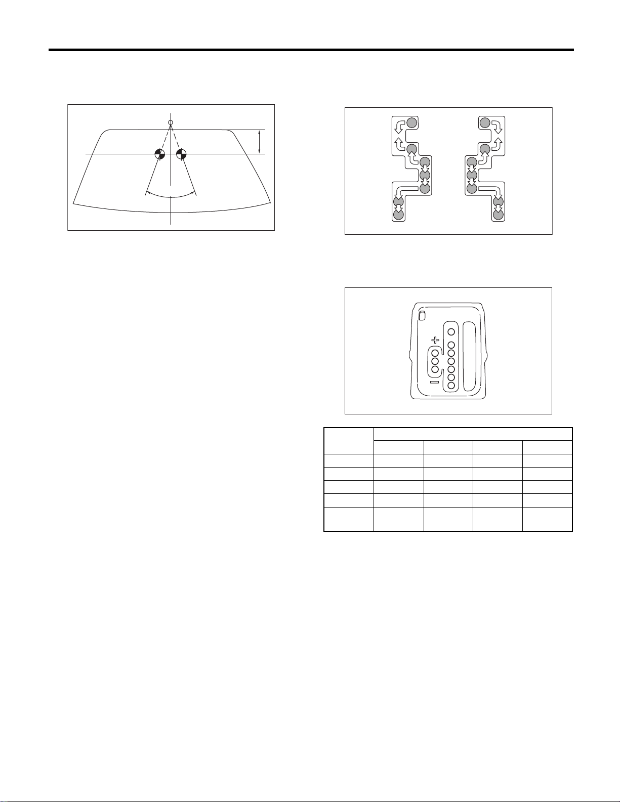
PRE-DELIVERY INSPECTION
Pre-delivery Inspection
Rear injection position:
A: 39 mm (2.36 in)
°°°°
B: 72
A
B
PI-00104
36.WIPER
Check the front and rear wipers for normal operations.
37.POWER WINDOW OPERATION CHECK
Manipulate the power window switches one by one
to check that each of the power windows goes up
and down with no abnormal noises.
38.SUNROOF
Check that the sunroof operates normally.
39.DOOR MIRROR
Check that the remote control mirror operates normally.
40.BRAKE TEST
Check the foot brake for normal operations.
41.PARKING BRAKE
Check the parking brake for normal operations.
When applying the parking brake with force of 196
N (20 kgf, 44 lb), check that the lever stroke of parking brake lever is 7 to 8 notches.
42.AT SHIFT CONTROL
Set the AT select lever to each gear position and
check the shifting while driving the vehicle.
P
R
N
D
3
2
1
(1) (2)
(1) RHD model
(2) LHD model
P
R
N
D
3
2
1
Selector
Position
D Yes Yes Yes Yes
3YesYesYes—
2YesYes——
1Yes———
Sports
shift
1st 2nd 3rd 4th
Yes Yes Yes Yes
Gear Position
PI-00112
AT-00761
43.HEATER & VENTILATION
PI-10
Operate the heater and ventilation system to check
for normal outlet selection, air inlet selection, airflow and heating capacity.
44.AIR CONDITIONER
Operate the air conditioner. Check that the A/C
compressor operates normally and enough cooling
is provided.
45.CRUISE CONTROL
Operate the cruise control system. Check that the
system is activated and deactivated correctly.
Page 75
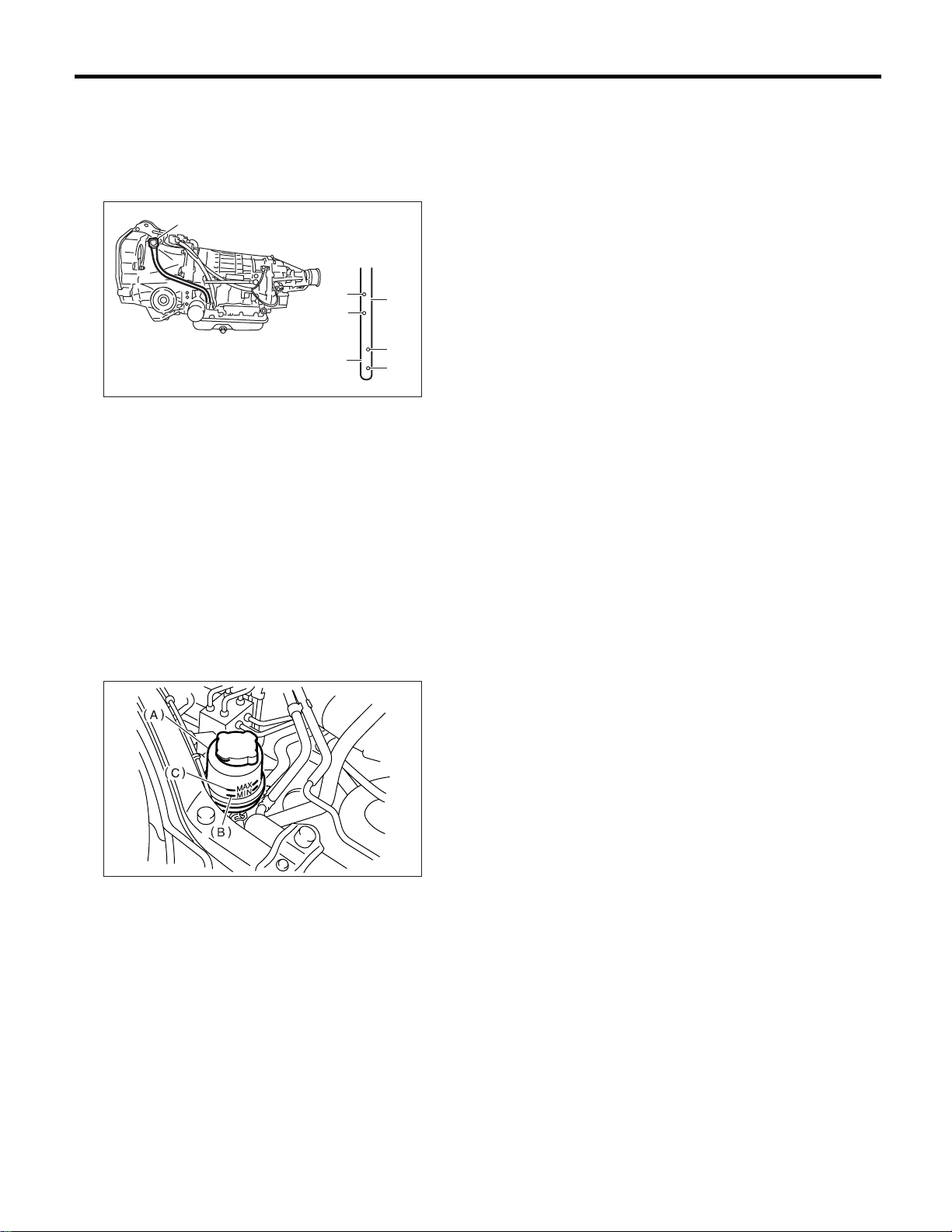
Pre-delivery Inspection
PRE-DELIVERY INSPECTION
46.ATF LEVEL
Check that the ATF level is normal when the engine
at idle. If insufficient, check that no leaks are found.
Then add the necessary amount of the specified
ATF.
(A)
(C)
(D)
(E)
(A) Level gauge
(B) ATF level range when “HOT” [70 — 80°C (158
— 176°F)]
(C) Upper level
(D) Lower level
(E) ATF level range when “COLD” [20 — 30°C (68
— 86°F)]
(B)
HOT
LF
(C)
LF
COLD
(D)
PM-00191
47.POWER STEERING FLUID LEVEL
Check that the power steering fluid level is normal.
If insufficient, check that no leaks are found. Then
add the necessary amount of the specified power
steering fluid.
49.WATER LEAK TEST
Spray the vehicle with water and check that no water enters the passenger compartment.
• Before performing the water leakage test, remove anything that may obstruct the operation or
which must be kept dry.
• Close all windows completely, and then close all
doors tightly. Close the hood and trunk lid before
starting the test.
• Connect a hose to a tap, and spray water on the
vehicle. The rate of water discharge must be approx. 20 — 25 2 (5.3 — 6.6 US gal, 4.4 — 5.5 Imp
gal) per minute.
When spraying water on areas adjacent to the floor
and wheel house, increase the pressure. When directing water on areas other than the floor portion
and wheel house, decrease the pressure. But the
force of water must be made strong occasionally by
pressing the end of the hose.
NOTE:
Be sure to keep the hose at least 10 cm (3.9 in)
from the vehicle.
Check the following areas:
• Front window and body framework mating portion
• Door mating portions
• Glass mating portions
• Rear quarter window mating portions
• Rear window and body framework mating portion
• Around roof drips
If any dampness in the compartment is discovered
after the water has been applied, carefully check all
areas that may have possibly contributed to the
leak.
PM-00070
(A) Reservoir tank
(B) MIN level
(C) MAX level
48.FLUID LEAK CHECK
Check the entire areas of the vehicle for any trace
of coolant/oil/fluid leaks.
50.APPEARANCE CHECK 2
1) Check the paint after removing the paint protective coating and washing the vehicle.
NOTE:
• Use of steam eases peeling off the warp guard.
• When performing on the vehicles left for a long
time, or during low temperature period, sprinkle
some water heated to 50 — 60°C (122 — 140°F)
over the vehicle to raise its surface temperature before peeling off the wrap guard.
Do not use the water heated to over 60°C (140°F).
• If the adhesive remains on the coated surface,
rub the portion with a flannel rag, etc. soaked with a
coat of coating wax or a solvent, such as oil benzene and IPA, and then wipe it off.
• Avoid adhesion of the solvent to resin or rubber
components. Do not use coating wax or a solvent
while the component surface temperature is high
due to hot weather, etc.
PI-11
Page 76

Pre-delivery Inspection
PRE-DELIVERY INSPECTION
• If the coated surface is swollen out due to seams
or moisture, expose the vehicle to the sun light for a
few hours. Otherwise, heat the portion with seams
or moisture using a dryer, etc.
• Dispose of the peeled wrap guard as burnable industrial garbage.
2) Check the whole vehicle body for stains, flaking,
damage caused by transportation, rust, dirt, cracks,
or blistering.
NOTE:
• It is better to determine an inspection pattern in
order to avoid missing an area, since the total inspection area is wide.
• It is desirable not to make corrections to the body
paint unless absolutely needed. However, if any
corrections are required to remove scratches or
rust, the area to be corrected must be limited as
much as possible. Re-painting and spray painting
must be avoided whenever possible.
3) Carefully check each window glass for scratches. Slight damage may be removed by polishing
with cerium oxide. (Half-fill a cup with cerium oxide,
and add warm water to it. Then agitate the content
until it turn to wax. Apply this wax to a soft cloth,
and polish the glass.)
4) Check each portion of the vehicle body and underside components for the formation of rust. If rust
is discovered, remove it with #80 — #180 emery
paper, and treat the surface with rust preventive.
After this treatment is completed, flush the portion
thoroughly, and prepare the surface for repair
painting.
5) Check each portion of the body and all of the
chrome parts for deformation or distortion. Also
check each lamp lens for cracks.
6) Peel the protective tape, vinyl wrapping and
identification seal attached to the following places.
• Seat
• Door trim
• Floor carpet
• Side sill
• Back of rear view mirror
PI-12
Page 77

PERIODIC MAINTENANCE SERVICES
PM
1. General Description ....................................................................................2
2. Schedule .....................................................................................................3
3. Engine Oil....................................................................................................7
4. Engine Oil Filter...........................................................................................9
5. Spark Plugs...............................................................................................10
6. V-belt.........................................................................................................11
7. Timing Belt ................................................................................................13
8. Fuel Line ...................................................................................................16
9. Fuel Filter ..................................................................................................17
10. Air Cleaner Element ..................................................................................18
11. Cooling System .........................................................................................19
12. Coolant......................................................................................................21
13. Idle Mixture................................................................................................23
14. Clutch System ...........................................................................................24
15. Transmission Gear Oil ..............................................................................26
16. Hill-holder System .....................................................................................27
17. ATF ...........................................................................................................28
18. Front & Rear Differential Gear Oil .............................................................30
19. Brake Line .................................................................................................32
20. Brake Fluid ................................................................................................34
21. Disc Brake Pads and Discs.......................................................................35
22. Brake Linings and Drums..........................................................................36
23. Suspension ...............................................................................................38
24. Wheel Bearing...........................................................................................40
25. Axle Boots & Joints ...................................................................................42
26. Steering System (Power Steering)............................................................43
Page
Page 78

General Description
PERIODIC MAINTENANCE SERVICES
1. General Description
A: GENERAL
Be sure to perform periodic maintenance in order to
maintain vehicle performance and find problems
before they become serious.
PM-2
Page 79
Schedule
O
PERIODIC MAINTENANCE SERVICES
2. Schedule
A: MAINTENANCE SCHEDULE 1
1. FOR EUROPE AREA
For periodic maintenance of over 120,000 km (75,000 miles) or 96 months, carry out inspection by referring
to the following table. For a maintenance period gone beyond these tables, apply them repeatedly as a set
of 120,000 km (75,000 miles) or 96 months.
Maintenance interval
[Number of months or km (miles), whichever occurs first]
Month 1224364860728496 Remarks
× 1,000 km 1.6 5 15 30 45 60 75 90 105 120
× 1,000 miles 1 3 9 19 28 38 47 56 66 75
1Engine oil RRRRRRRR
2Engine oil filter RRRRRRRR
3 Spark plug For Turbo R
Others RRRR
4Drive belt(s) IIIIIIII
5 Camshaft drive belt R
6 Fuel line I I I I
7 Fuel filter R R
8 Air cleaner element I R I R I R I R
9 Cooling system I I I I
10 Coolant R R R R
11 Clutch system
IIII
12 Hill-holder system I I I I
13 Transmission oil I R I R
14 ATF I R I R
15 Front & rear differential I R I R
16 Brake line I I I I
17 Brake fluid R R R R
18Disk brake pads & discs IIIIIIII
19 Brake linings & drums I I I I
20 Parking brake I I I I
21 Suspension I I I I
22 Wheel bearing (I)
23Axle boot & joint IIIIIIII
24 Steering system I I I I
25 Clutch cable R
Adjust the clutch
pedal free play
every 1,600 km
(1,000 miles)
Symbols used:
R: Replace
I: Inspection
(I): Recommended service for safe vehicle operation.
TE:
N
(1) When the vehicle is used in extremely dusty conditions, the air cleaner element should be replaced more often.
(2) ATF filter is a maintenance free part. ATF filter needs replacement, when it is physically damaged or ATF leaked.
PM-3
Page 80
Schedule
PERIODIC MAINTENANCE SERVICES
2. EXCEPT FOR EUROPE AREA
For periodic maintenance of over 50,000 km (30,000 miles) or 48 months, carry out inspections by referring
to the following tables. For a maintenance period gone beyond these tables, apply them repeatedly as a set
of 50,000 km (30,000 miles) or 48 months.
Maintenance Interval
[Number of months or km (miles), whichever occurs first]
Months 12 24 36 48 Remarks
× 1,000 km 5 12.5 25 37.5 50
× 1,000 miles 3 7.5 15 22.5 30
1 Engine oil R R R R
2 Engine oil filter R R R R
For periodic maintenance of over 100,000 km (60,000 miles) or 48 months, carry out inspections by referring
to the following tables. For a maintenance period gone beyond these tables, apply them repeatedly as a set
of 100,000 km (60,000 miles) or 48 months.
Maintenance Interval
[Number of months or km (miles), whichever occurs first]
Months 12 24 36 48 Remarks
× 1,000 km 1.6 25 50 75 100
× 1,000 miles 1 15 30 45 60
3 Spark plugs For Turbo R
Others R R R R
4 Drive belt(s) I I I I
5 Camshaft drive belt R
6 Fuel line I I
7 Fuel filter R R
8 Air cleaner element I R I R
9 Cooling system I I
10 Coolant R R
11 Idle mixture
12 Clutch system
13 Hill-holder system I I I I
14 Transmission oil R R
15 ATF R R
16 Front & rear differential oil R R
17 Brake line I I
18 Brake fluid R R
19 Disc brake pads & discs I I I I
20 Brake linings and drums I I
21 Parking brake I I I I
22 Suspension I I I I
23 Wheel bearing (I)
24 Axle boots & joints I I I I
25 Steering system (Power steering) I I I I
26 Clutch cable R
IIIII
IIII
For models without catalyst converter
Adjust the clutch pedal free play
every 1,600 km (1,000 miles)
Symbols used:
R: Replace
I: Inspection
(R) or (I): Recommended service for safe vehicle operation.
PM-4
Page 81
Schedule
PERIODIC MAINTENANCE SERVICES
NOTE:
(1) When the vehicle is used in extremely dusty conditions, the air cleaner element should be replaced more often.
(2) ATF filter is a maintenance free part. ATF filter needs replacement, when it is physically damaged or ATF leaked.
B: MAINTENANCE SCHEDULE 2
1. EUROPE AREA
Item Every
Engine oil Replace
Engine oil filter Replace
Fuel line 12 months
9,000 miles
Transmission oil Replace
ATF Replace
Front & rear differential oil
Brake line 12 months
9,000 miles
Brake fluid 12 months
9,000 miles
Brake pads 12 months
9,000 miles
Brake linings
and drums
Parking brake 12 months
Suspension 12 months
Axle boots &
joints
Steering system
(Power steering)
12 months
9,000 miles
9,000 miles
9,000 miles
12 months
9,000 miles
12 months
9,000 miles
Repeat short
distance drive
more fre-
quently
more fre-
quently
IIII15,000 km
IIII15,000 km
IIII15,000 km
IIII15,000 km
Repeat
rough/muddy
road drive
III15,000 km
III15,000 km
Extremely
cold weather
area
Replace
more fre-
quently
Replace
more fre-
quently
Salt or other
corrosive
used or
coastal area
I15,000 km
I15,000 km
High humid-
ity or moun-
tain area
R15,000 km
Repeat tow-
ing trailer
Replace
more fre-
quently
Replace
more fre-
quently
more fre-
quently
more fre-
quently
Replace
more fre-
quently
PM-5
Page 82
PERIODIC MAINTENANCE SERVICES
2. EXCEPT FOR EUROPE AREA
Schedule
Item Every
Engine oil Replace
Engine oil filter Replace
Fuel line 6 months
7,500 miles
Transmission oil Replace
ATF Replace
Front & rear differential oil
Brake line 6 months
7,500 miles
Brake fluid 12 months
15,000 miles
Brake pads 6 months
7,500 miles
Brake linings
and drums
Parking brake 6 months
Suspension 6 months
Axle boots &
joints
Steering system
(Power steering)
6 months
7,500 miles
7,500 miles
7,500 miles
6 months
7,500 miles
6 months
7,500 miles
Repeat short
distance drive
more fre-
quently
more fre-
quently
IIII12,500 km
IIII12,500 km
IIII12,500 km
IIII12,500 km
Repeat
rough/muddy
road drive
III12,500 km
III12,500 km
Extremely
cold weather
area
Replace
more fre-
quently
Replace
more fre-
quently
Salt or other
corrosive
used or
coastal area
I12,500 km
I12,500 km
High humid-
ity or moun-
tain area
R25,000 km
Repeat tow-
ing trailer
Replace
more fre-
quently
Replace
more fre-
quently
more fre-
quently
more fre-
quently
Replace
more fre-
quently
PM-6
Page 83
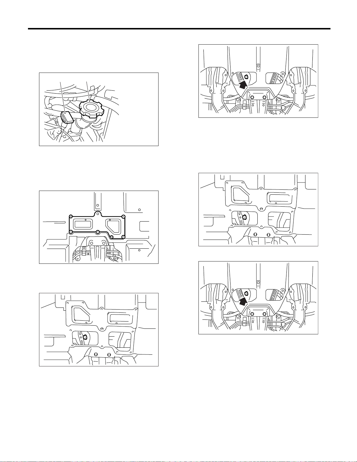
Engine Oil
PERIODIC MAINTENANCE SERVICES
3. Engine Oil
A: REPLACEMENT
1) Open the engine oil filler cap for quick draining of
the engine oil.
(A)
(A) Oil level gauge
(B) Oil filler cap
2) Remove the dip of service hole cover. (Turbo
model)
(B)
PM-00155
• SOHC MODEL
LU-00193
4) Replace the drain plug gasket.
5) Tighten the engine oil drain plug after draining
engine oil.
Tightening torque:
44 N·m (4.5 kgf-m, 33 ft-lb)
• DOHC TURBO MODEL
LU-00185
3) Drain the engine oil by loosening engine oil drain
plug.
• DOHC TURBO MODEL
LU-00186
LU-00186
• SOHC MODEL
LU-00193
PM-7
Page 84
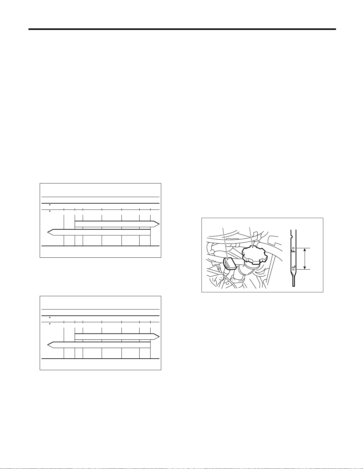
PERIODIC MAINTENANCE SERVICES
Engine Oil
6) Fill engine oil through the filler pipe up to center
between upper level and lower level. Make sure
that the vehicle is placed level when checking oil
level. Use engine oil of proper quality and viscosity,
selected in accordance with the table in figure.
Recommended oil
API classification
SL or SJ with the words “Energy Conserving or Energy conserving II”, CCMC speci-
fication G4 or G5, ACEA specification A1,
A2 or A3, or New API mark displayed on
the container (If it is impossible to get SL
or SJ grade, you may use SG or SH grade.)
Engine oil capacity
Upper level:
Approx. 4.0 2 (4.2 US qt, 3.5 Imp qt)
Lower level:
Approx. 3.0 2 (3.2 US qt, 2.6 Imp qt)
• SOHC MODEL
SAE (1)
4030150-15-20-30( C)
5-4-22( F)
104865932
NOTE:
• When replenishing oil, it does not matter if the oil
to be added is a different brand from that in the engine; however, use oil having the API classification
and SAE viscosity No. designated by SUBARU.
• If vehicle is used in desert areas with very high
temperatures or for other heavy duty applications,
the following viscosity oils may be used:
API classification: SL or SJ.
SAE Viscosity No.: 30, 40, 10W-50, 20W-40, 20W50
7) Close the engine oil filler cap.
8) Start the engine and warm it up for a time.
9) After the engine stops, recheck the oil level.
<Ref. to PM-8, INSPECTION, Engine Oil.>
B: INSPECTION
1) Park the vehicle on a level surface.
2) Remove the oil level gauge and wipe it clean.
3) Reinsert the level gauge all the way. Be sure that
the level gauge is correctly inserted and in the
proper orientation.
4) Remove it again and note the reading. If the engine oil level is below the “L” line, add oil to bring
the level up to the “F” line.
10W-30,10W-40
5W-30,0W-20 (2)
LU-00071
(1) Viscosity No. and applicable temperature
(2) Preferred
• EXCEPT FOR SOHC MODEL
SAE (1)
4030150-15-20-30( C)
5-4-22( F)
10W-30,10W-40
5W-30 (2)
(1) Viscosity No. and applicable temperature
(2) Preferred
104865932
LU-00076
The proper viscosity helps vehicle get good cold
and hot starting by reducing viscous friction and
thus increasing cranking speed.
(A)
(A) Oil level gauge
(B) Oil filler cap
(C) Upper level
(D) Lower level
(E) Approx. 1 2 (1.1 Us qt, 0.9 lmp qt)
(B)
(C)
(E)
(D)
LU-00138
5) After turning off the engine, wait a few minutes
for the oil to drain back into oil pan before checking
the level.
6) Just after driving or while the engine is warm, engine oil level may show in the range between the
“F” line and the notch mark. This is caused by thermal expansion of the engine oil.
7) To prevent overfilling the engine oil, do not add
oil above the “F” line when the engine is cold.
PM-8
Page 85
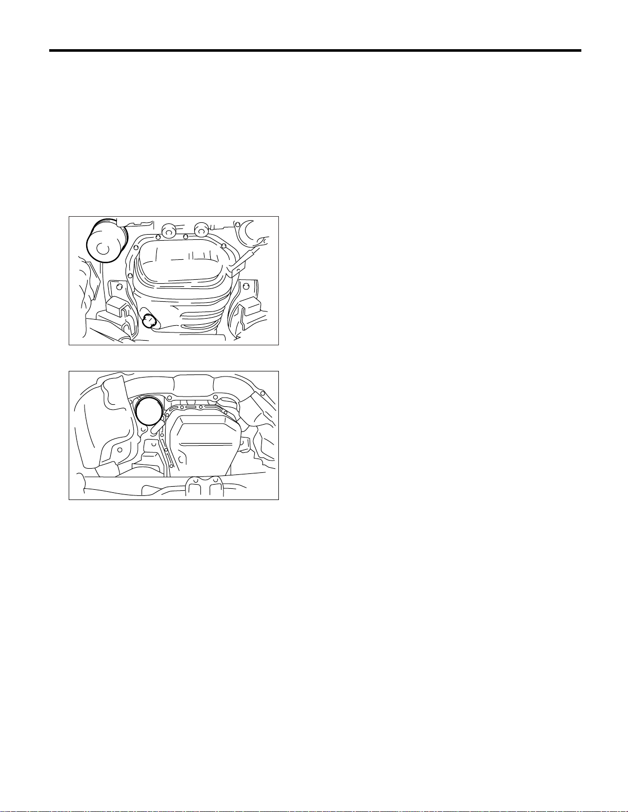
Engine Oil Filter
4. Engine Oil Filter
A: REPLACEMENT
1) Remove the under cover.
2) Remove the oil filter with ST.
ST 498547000 OIL FILTER WRENCH (Outer
diameter 80 mm (3.15 in))
ST 18332AA000 OIL FILTER WRENCH (Outer
diameter 68 mm (2.68 in))
ST 18332AA010 OIL FILTER WRENCH (Outer
diameter 65 mm (2.56 in))
• SOHC MODEL
PERIODIC MAINTENANCE SERVICES
LU-00194
• DOHC TURBO MODEL
LU-00190
3) Get a new oil filter and apply a thin coat of engine
oil to the seal rubber.
4) Install the oil filter by turning it by hand, being
careful not to damage the seal rubber.
5) Tighten more (approx. 1 turn for outer diameter
68 mm (2.68 in) oil filter, and 2/3 to 3/4 turn except
for outer diameter 68 mm (2.68 in) oil filter) after the
seal rubber contacts the cylinder block. Do not
tighten excessively, or oil may leak.
6) After installing the oil filter, run the engine and
make sure that no oil is leaking around seal rubber.
NOTE:
The filter element and filter case are permanently
joined; therefore, interior cleaning is not necessary.
7) Check the engine oil level. <Ref. to PM-8, INSPECTION, Engine Oil.>
PM-9
Page 86
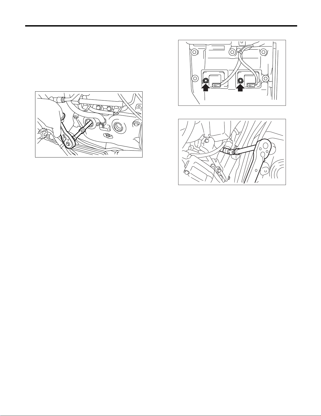
PERIODIC MAINTENANCE SERVICES
Spark Plugs
5. Spark Plugs
A: REPLACEMENT
1. SOHC MODEL
1) Remove the intake duct and intake chamber.
2) Remove the washer tank and put it aside.
3) Disconnect the spark plug cord.
4) Remove the spark plug with a plug-wrench.
PM-00001
5) Set the new spark plugs.
Recommended spark plug:
1.6 L SOHC model (with catalytic converter)
CHAMPION: RC8YC4
NGK: BKR6E-11 (Alternate)
1.6 L SOHC model (without catalytic converter)
NGK: BKR6E
2.0 and 2.5 L SOHC model (with catalytic converter)
CHAMPION: RC10YC4
NGK: BKR5E-11 (Alternate)
2.0 SOHC model (without catalytic converter)
NGK: BKR6E
6) Tighten the spark plug lightly with hand, and
then secure with a plug-wrench to the specified
torque.
Tightening torque:
21 N·m (2.1 kgf-m, 15.2 ft-lb)
NOTE:
• Be sure to place the gasket between the cylinder
head and spark plug.
• If a torque wrench is not available, tighten the
spark plug until gasket contacts cylinder head; then
tighten further 1/4 to 1/2 turns.
5) Remove the ignition coil.
PM-00145
6) Remove the spark plug with a spark plug socket.
PM-00112
7) Set new spark plugs.
Recommended spark plug:
2.0 L DOHC Turbo model
NGK: PFR6G
8) Tighten the spark plug lightly with hand, and
then secure with a plug-wrench to the specified
torque.
Tightening torque:
21 N·m (2.1 kgf-m, 15.2 ft-lb)
9) Tighten the ignition coil.
Tightening torque:
16 N·m (1.6 kgf-m, 11.7 ft-lb)
NOTE:
• Be sure to place the gasket between the cylinder
head and spark plug.
• If a torque wrench is not available, tighten the
spark plug until gasket contacts cylinder head: then
tighten further 1/4 to 1/2 turns.
2. DOHC MODEL
1) Disconnect the battery cables, and then remove
the battery and battery carrier.
2) Remove the washer tank and put it aside.
3) Remove the air cleaner lower case.
4) Disconnect the connector from ignition coil.
PM-10
Page 87
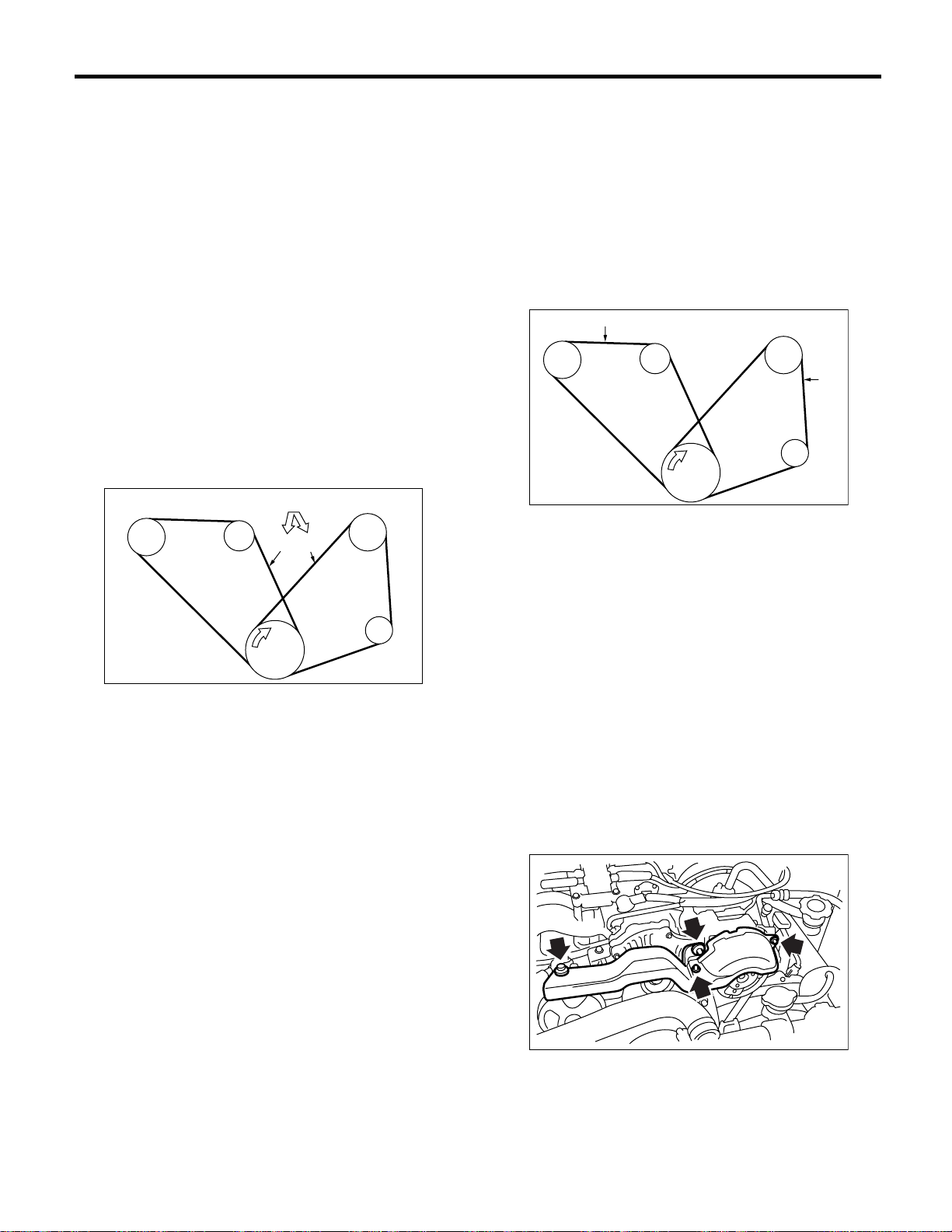
V-belt
PERIODIC MAINTENANCE SERVICES
6. V-belt
A: INSPECTION
1) Replace the belts, if cracks, fraying or wear is
found.
2) Check the V-belt tension and adjust it if necessary by changing the generator installing position
and/or idler pulley installing position. <Ref. to PM11, REPLACEMENT, V-belt.>
Belt tension (without belt tension gauge)
(A)
When installing new one: 7 — 9 mm (0.276
— 0.354 in)
At inspection: 9 — 11 mm (0.354 — 0.433
in)
(B)
When installing new one: 7.5 — 8.5 mm
(0.295 — 0.335 in)
At inspection: 9.0 — 10.0 mm (0.354 —
0.394 in)
98 N (10kg)
P/S
(A) Front side belt
(B) Rear side belt
C/P Crankshaft pulley
GEN Generator
P/S Power steering oil pump pulley
A/C Air conditioning compressor pulley
I/P Idler pulley
GEN
C/P
(A)
(B)
A/C
I/P
PM-00002
Belt tension (with belt tension gauge)
(A)
When installing new one: 640 — 785 N
(65.3 — 80.0 kgf, 144 — 176 lb)
At inspection: 490 — 640 N (50 — 65 kgf,
110 — 144 lb)
(B)
When installing new one: 620 — 760 N (63
— 77 kgf, 140 — 170 lb)
At inspection: 350 — 450 N (36 — 46 kgf, 79
— 101 lb)
(A)
P/S
(A) Front side belt
(B) Rear side belt
C/P Crank pulley
GEN Generator
P/S Power steering oil pump pulley
A/C A/C compressor pulley
I/P Idler pulley
GEN
C/P
A/C
(B)
I/P
PM-00154
B: REPLACEMENT
1. FRONT SIDE BELT (DRIVING POWER
STEERING OIL PUMP AND GENERATOR)
NOTE:
Wipe off any oil or water on the belt and pulley.
1) Remove the V-belt cover.
NON-TURBO MODEL
PM-11
PM-00003
Page 88
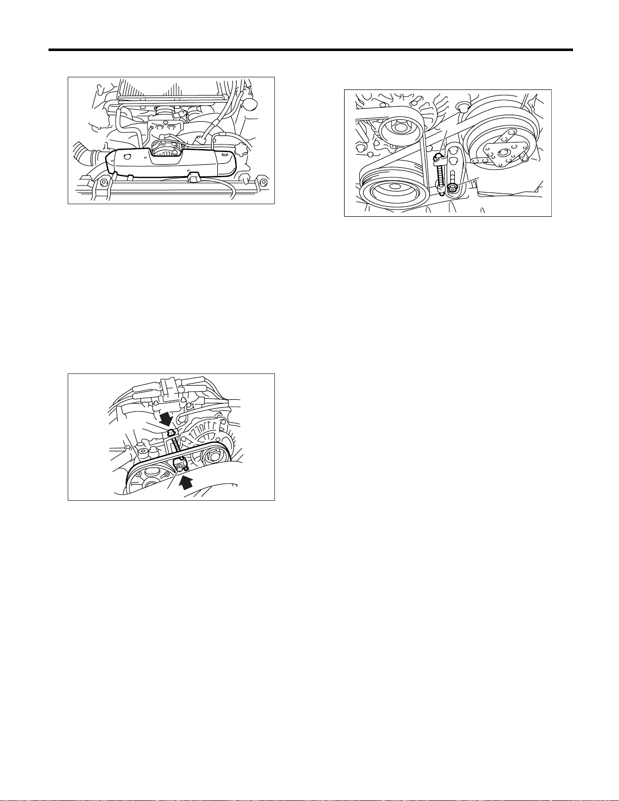
PERIODIC MAINTENANCE SERVICES
V-belt
TURBO MODEL
SC-00096
2) Loosen the lock bolt (A).
3) Loosen the slider bolt (B).
4) Remove the front side belt (C).
5) Install a new belt, and tighten the slider bolt so as
to obtain the specified belt tension.
6) Tighten the lock bolt (A).
7) Tighten the slider bolt (B).
Tightening torque:
Lock bolt:
25 N·m (2.5 kgf-m, 18 ft-lb)
Slider bolt:
8 N·m (0.8 kgf-m, 5.8 ft-lb)
Tightening torque:
23 N·m (2.3 kgf-m, 17.0 ft-lb)
(B)
(A)
PM-00005
(B)
(C)
(A)
PM-00004
2. REAR SIDE BELT (DRIVING AIR CONDITIONER)
NOTE:
Wipe off any oil or water on the belt and pulley.
1) Remove the front side belt.
2) Loosen the lock nut (A).
3) Loosen the slider bolt (B).
4) Remove the rear side belt.
5) Install a new belt, and tighten the slider bolt so as
to obtain the specified belt tension.
6) Tighten the lock nut (A).
7) Install the front side belt.
SOHC model
<Ref. to ME(H4SO)-43, FRONT SIDE BELT, INSTALLATION, V-belt.>
DOHC Turbo model
<Ref. to ME(H4DOTC)-54, FRONT SIDE BELT,
INSTALLATION, V-belt.>
PM-12
Page 89
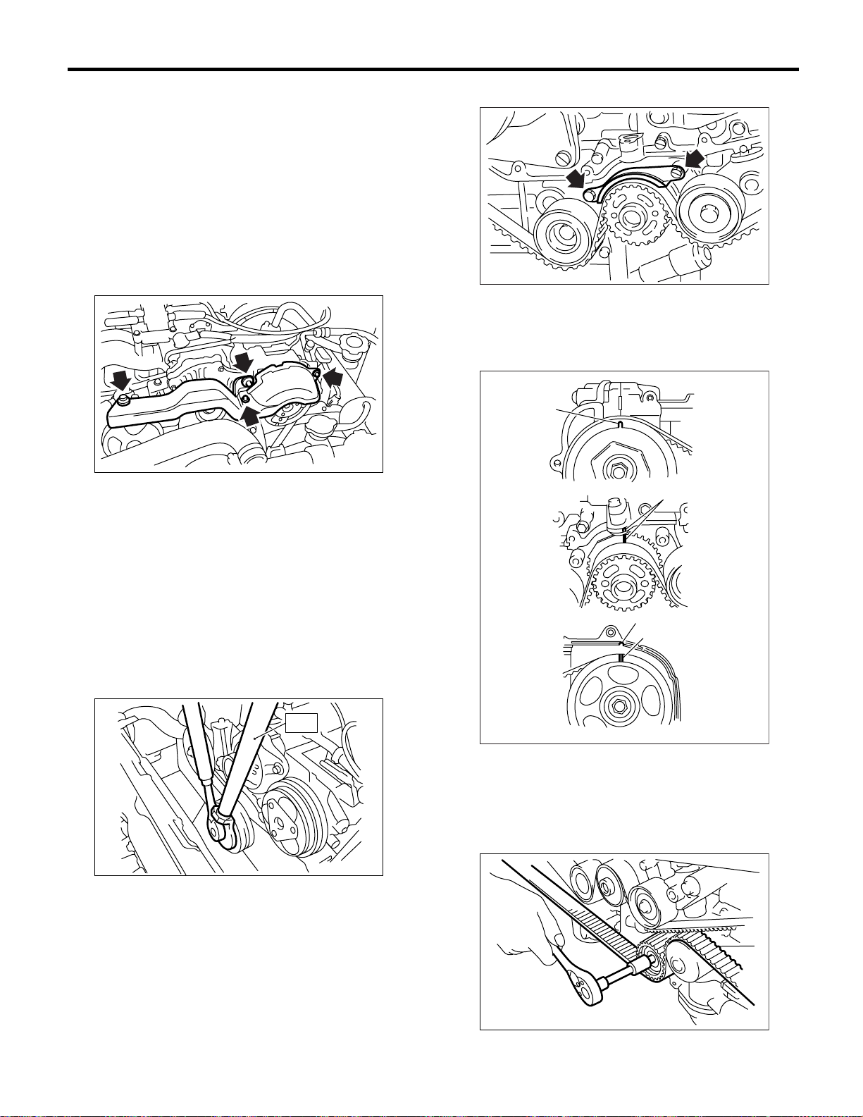
Timing Belt
PERIODIC MAINTENANCE SERVICES
7. Timing Belt
A: REPLACEMENT
1. NON-TURBO MODEL
1) Remove the radiator fan and air conditioner fan.
<Ref. to CO(H4SO)-23, Radiator Main Fan and
Fan Motor.>, <Ref. to CO(H4SO)-24, Radiator Sub
Fan and Fan Motor.>
2) Shield the radiator from any damage using cardboard and blanket.
3) Remove the V-belt cover.
PM-00003
4) Remove the V-belts. <Ref. to ME(H4SO)-43, Vbelt.>
5) Remove the air conditioning compressor drive
belt tensioner.
6) To lock the crankshaft, use ST. Remove the pulley bolt.
2.5 L model:
ST 499977100 CRANKSHAFT PULLEY
WRENCH
Except for 2.5 L model:
ST 499977400 CRANKSHAFT PULLEY
WRENCH
10) Remove the timing belt guide. (MT model)
PM-00008
11) Turn the crankshaft and align alignment marks
on crankshaft, and right and left camshaft sprockets with notches of belt cover and cylinder block.
ST 499987500 CRANKSHAFT SOCKET
(B)
(B)
(A)
(B)
ST
7) Remove the crankshaft pulley.
8) Remove the left side belt cover.
9) Remove the front timing belt cover.
PM-00009
(A) Notch
(B) Alignment mark
12) Remove the belt idler.
13) Remove the belt idler (No. 2).
PM-00007
PM-00010
14) Remove the timing belt.
PM-13
Page 90
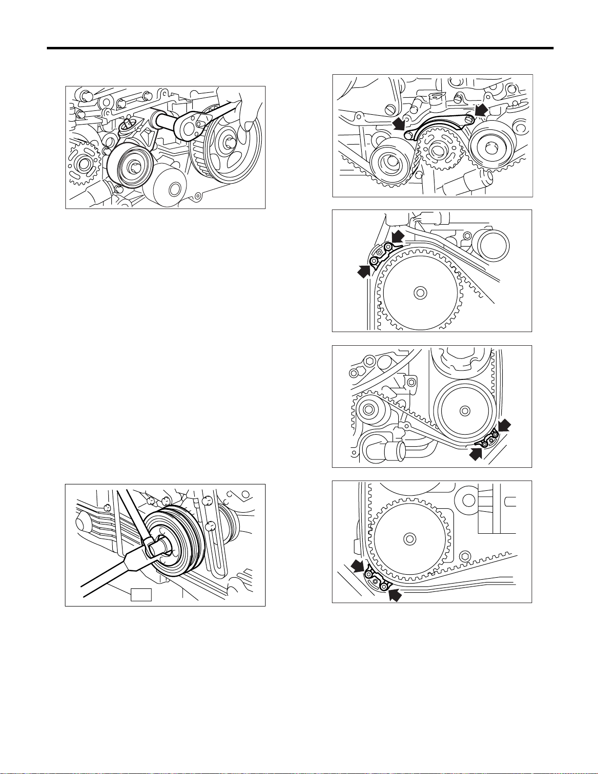
PERIODIC MAINTENANCE SERVICES
Timing Belt
15) Remove the automatic belt tension adjuster assembly.
PM-00011
16) Install in the reverse order of removal. <Ref. to
ME(H4SO)-49, INSTALLATION, Timing Belt Assembly.>
2. DOHC MODEL
1) Remove the radiator fan and air conditioner fan.
<Ref. to CO(H4DOTC)-28, Radiator Main Fan and
Fan Motor.>, <Ref. to CO(H4DOTC)-30, Radiator
Sub Fan and Fan Motor.>
2) Protect the radiator with cardboard and blanket.
3) Remove the V-belts. <Ref. to ME(H4DOTC)-54,
V-belt.>
4) Remove the air conditioning compressor drive
belt tensioner.
5) Remove the pulley bolt. To lock the crankshaft
use ST.
Except for STi model:
ST 499977300 CRANKSHAFT PULLEY
WRENCH
STi model:
ST 499977300 CRANKSHAFT PULLEY
WRENCH
11) Remove the timing belt guide. (MT model)
PM-00008
ME-00727
ME-00728
ST
PM-00093
6) Remove the crankshaft pulley.
7) Remove the air conditioning compressor drive
belt tensioner.
8) Remove the belt cover (LH).
9) Remove the belt cover (RH).
10) Remove the front belt cover.
ME-00729
12) Turn the crankshaft and align alignment marks
on crankshaft, and right and left camshaft sprockets with notches of belt cover and cylinder block. To
turn the crankshaft, use ST.
PM-14
Page 91
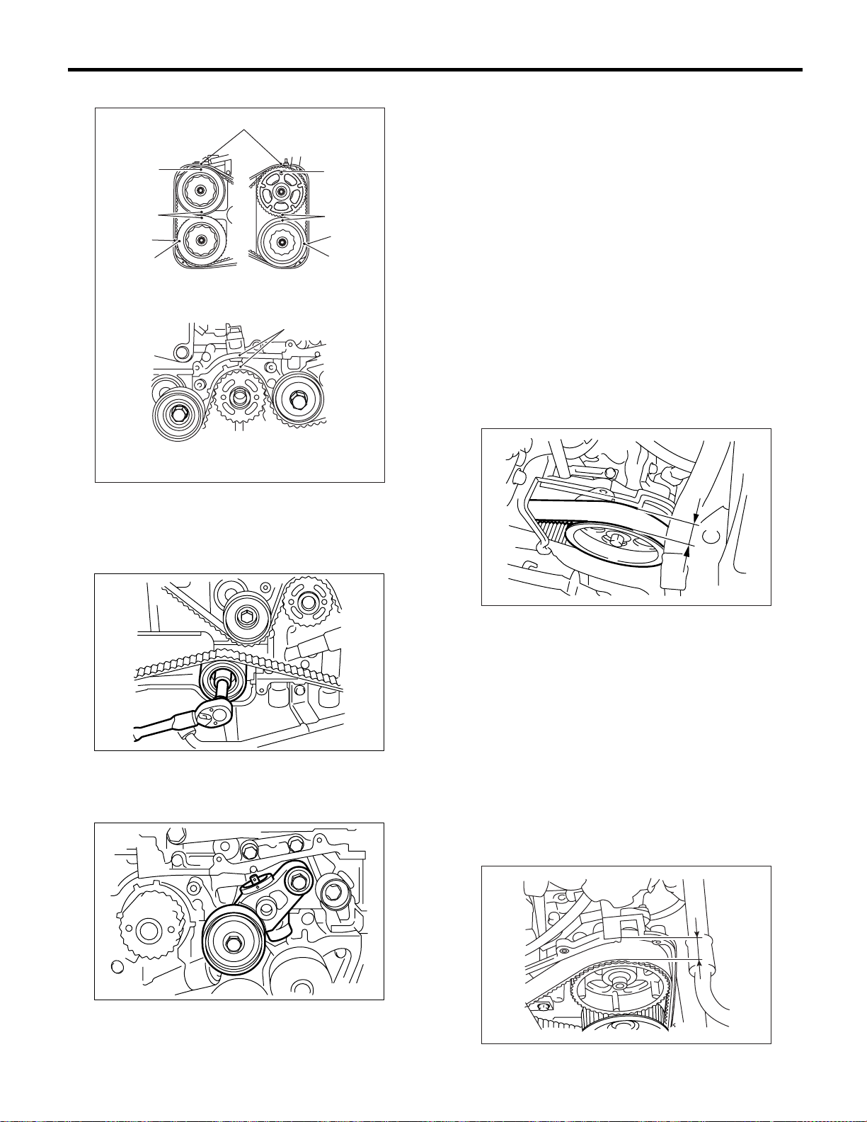
Timing Belt
PERIODIC MAINTENANCE SERVICES
ST 499987500 CRANKSHAFT SOCKET
(A)
(B)
(B)
(A)
(B)
(B)
(A) Notch
(B) Alignment mark
(B)
(B)
(A)
(B)
PM-00156
CAUTION:
When installing the timing belt, be sure to align
all alignment marks on the belt with corresponding marks on the sprockets. If incorrectly
installed, interference between pistons and
valves may occur.
B: INSPECTION
1. SOHC MODEL
1) Remove the front timing belt cover and timing
belt cover (LH).
2) While cranking the engine at least four rotations,
check the timing belt back surface for cracks or
damage. Replace the faulty timing belt as needed.
3) Measure the timing belt width W. If it is less than
27 mm (1.06 in), check idlers, tensioner, water
pump pulley and cam sprocket to determine idler
alignment (squareness). Replace the worn timing
belt.
W
13) Remove the belt idler.
PM-00095
14) Remove the timing belt.
15) Remove the automatic belt tension adjuster assembly.
PM-00016
4) Install the front timing belt cover and timing belt
cover (LH).
2. DOHC MODEL
1) Remove the timing belt cover (LH).
2) While cranking the engine at least four rotations,
check the timing belt back surface for cracks or
damage. Replace the faulty timing belt as needed.
3) Measure the timing belt width W. If it is less than
30 mm (1.18 in), check idlers, tensioner, water
pump pulley and cam sprocket to determine idler
alignment (squareness). Replace the worn timing
belt.
4) Install the timing belt cover (LH).
W
PM-00096
16) Install in the reverse order of removal. <Ref. to
ME(H4DOTC)-58, Timing Belt Assembly.>
PM-00097
PM-15
Page 92

Fuel Line
PERIODIC MAINTENANCE SERVICES
8. Fuel Line
A: INSPECTION
The fuel line is located mostly internally, so check
pipes, areas near pipes, and engine compartment
piping for rust, hose damage, loose bands, etc. If
faulty parts are found, repair or replace them.
SOHC model
<Ref. to FU(H4SO)-63, Fuel Delivery, Return and
Evaporation Lines.>
DOHC Turbo model
<Ref. to FU(H4DOTC)-69, Fuel Delivery, Return
and Evaporation Lines.>
PM-16
Page 93

Fuel Filter
9. Fuel Filter
A: REPLACEMENT
For fuel filter replacement procedures, refer to “FU”
section.
SOHC model
<Ref. to FU(H4SO)-60, Fuel Filter.>
DOHC Turbo model
<Ref. to FU(H4DOTC)-66, Fuel Filter.>
B: INSPECTION
1) If it is clogged, or if replacement interval has
been reached, replace it.
2) If water is found in it, shake and expel the water
from inlet port.
PERIODIC MAINTENANCE SERVICES
PM-17
Page 94
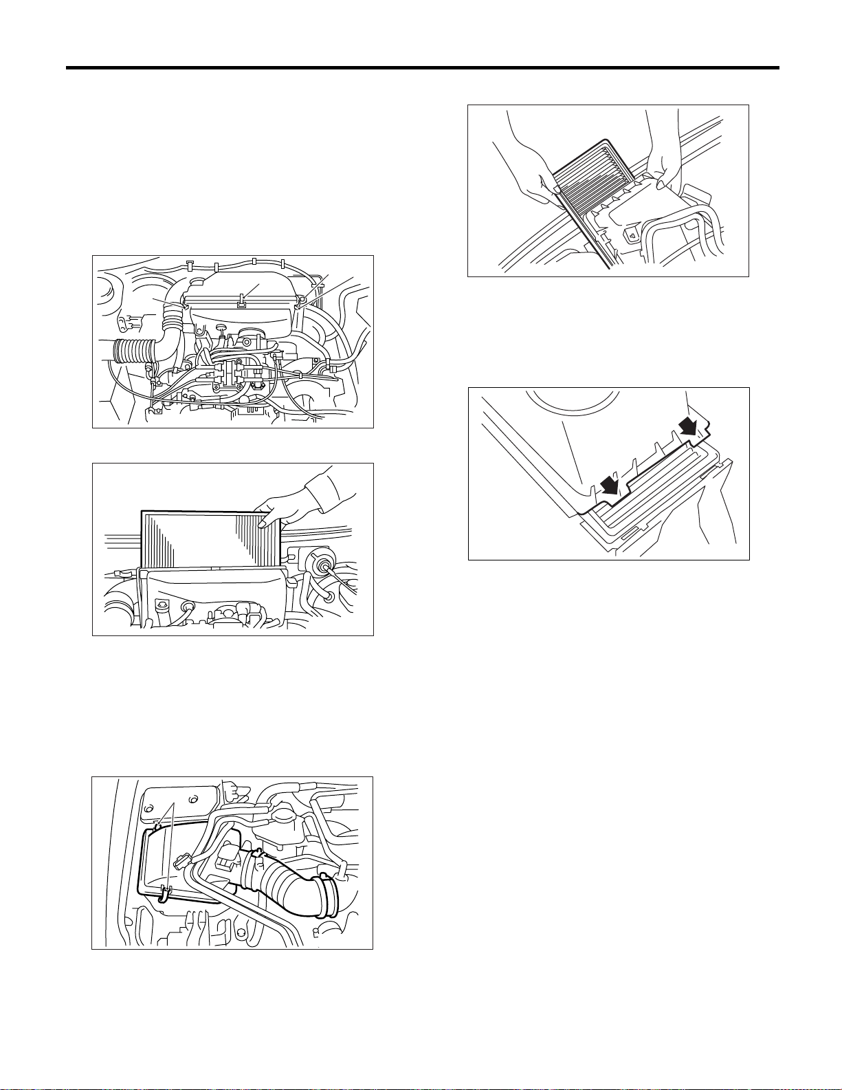
PERIODIC MAINTENANCE SERVICES
Air Cleaner Element
10.Air Cleaner Element
A: REPLACEMENT
1. NON-TURBO MODEL
1) Remove the air intake duct from air cleaner
case.
2) Remove the bolt (A) which installs air cleaner
case to stays.
3) Remove the clip (B) above the air cleaner case.
(A)
(B)
(B)
4) Remove the air cleaner.
(B)
IN-00039
2) Remove the air cleaner.
PM-00098
3) Install in the reverse order of removal.
NOTE:
Align the protruding portion of air cleaner upper
cover with holes of air cleaner lower case, then secure upper cover to case.
PM-00142
5) Install in the reverse order of removal.
NOTE:
Fasten with a clip after inserting the lower tab of the
case.
2. TURBO MODEL
1) Remove the clip (B) above the air cleaner case.
(B)
PM-00099
PM-00100
PM-18
Page 95
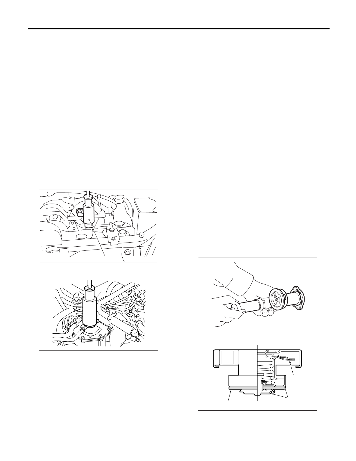
Cooling System
PERIODIC MAINTENANCE SERVICES
11.Cooling System
A: INSPECTION
1) Check the radiator for leakage, filling it with coolant and attach the radiator cap tester (A) to filler
neck. Then apply a pressure.
Check the following points:
Non-turbo model
157 kPa (1.6 kg/cm
Turbo model
122 kPa (1.2 kg/cm
• Each portion of radiator for leakage
• Hose joints and other connections for leakage
NOTE:
• For turbo model, be sure to install the tester to filler tank side.
• When attaching or detaching tester and when
operating tester, use special care not to deform radiator filler neck.
NON-TURBO MODEL
2
, 23 psi)
2
, 18 psi)
(A)
PM-00128
NOTE:
Rust or dirt on the cap may prevent the valve from
functioning normally: be sure to clean the cap before testing.
Raise the pressure until the needle of gauge stops
and see if the pressure can be retained for 5 to 6
seconds. The radiator cap is normal if a pressure
above the service limit value has been maintained
for this period.
Radiator cap valve open pressure
Non-turbo model
Standard value:
2
93 — 123 kPa (0.95 — 1.25 kg/cm
, 14 — 18
psi)
Service limit:
2
83 kPa (0.85 kg/cm
, 12 psi)
Turbo model
Filler tank side:
Standard value:
2
93 — 123 kPa (0.95 — 1.25 kg/cm
, 14 — 18
psi)
Service limit:
83 kPa (0.85 kg/cm
2
, 12 psi)
Radiator side:
Standard value:
2
122 — 152 kPa (1.24 — 1.55 kg/cm
, 18 —
22 psi)
Service limit:
2
112 kPa (1.14 kg/cm
, 16 psi)
TURBO MODEL
(A)
PM-00150
• When performing this check, be sure to keep the
engine stationary and fill the radiator with coolant.
• Wipe off check points before applying pressure.
• Use care not to spill coolant when detaching the
tester from radiator.
• Do not remove the radiator side cap. (Turbo
model)
2) Check the radiator cap valve open pressure using radiator cap tester.
(A)
(A) Deformation
(B) Deformation, damage, rust
PM-00023
(A)
(B)
PM-00089
PM-19
Page 96

Cooling System
PERIODIC MAINTENANCE SERVICES
3) Start the engine, and then check it does not
overheat or it is cooled excessively. If it overheats
or it is cooled excessively, check the cooling system.
SOHC model
<Ref. to CO(H4SO)-15, Water Pump.>
<Ref. to CO(H4SO)-18, Thermostat.>
<Ref. to CO(H4SO)-19, Radiator.>
<Ref. to CO(H4SO)-22, Radiator Cap.>
DOHC Turbo model
<Ref. to CO(H4DOTC)-20, Water Pump.>
<Ref. to CO(H4DOTC)-22, Thermostat.>
<Ref. to CO(H4DOTC)-23, Radiator.>
<Ref. to CO(H4DOTC)-27, Radiator Cap.>
4) Check the electric fan operates using Subaru
Select Monitor, when the coolant temperature exceeds 95°C (203°F). If not operate, check the electric fan system.
SOHC model
<Ref. to CO(H4SO)-6, Radiator Main Fan System.>
<Ref. to CO(H4SO)-9, Radiator Sub Fan System.>
DOHC Turbo model
<Ref. to CO(H4DOTC)-8, Radiator Main Fan System.>
<Ref. to CO(H4DOTC)-13, Radiator Sub Fan System.>
PM-20
Page 97
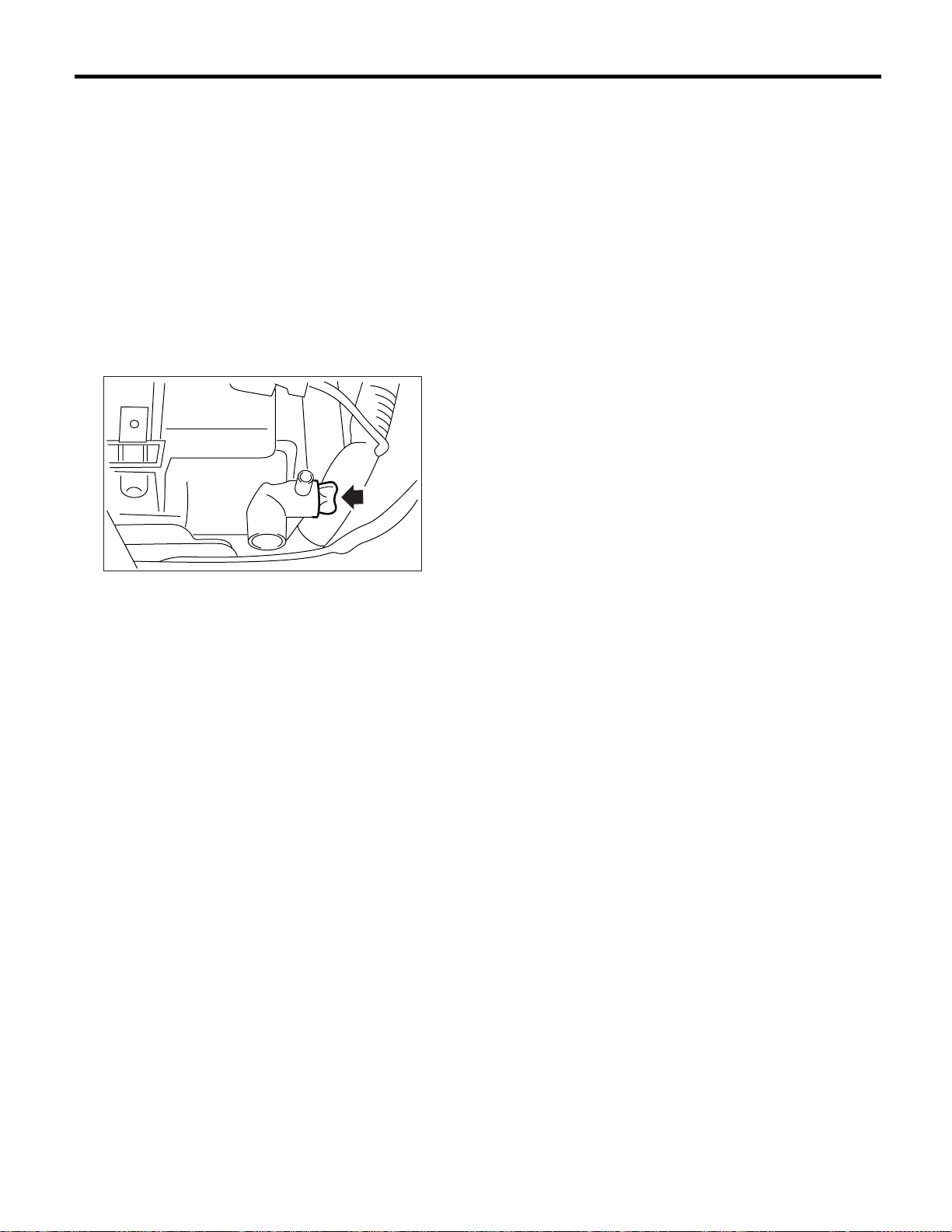
Coolant
PERIODIC MAINTENANCE SERVICES
12.Coolant
A: REPLACEMENT
1. REPLACEMENT OF COOLANT
WARNING:
The radiator is of the pressurized type. Do not
attempt to open the radiator cap immediately
after the engine has been stopped.
1) Lift-up the vehicle.
2) Remove the under cover.
3) Place a container under drain pipe.
4) Loosen and remove the drain cock to drain engine coolant into container.
NOTE:
The SUBARU Genuine Coolant containing antifreeze and anti-rust agents is especially made for
SUBARU engine, which has an aluminum crankcase. Always use SUBARU Genuine Coolant,
since other coolant may cause corrosion.
10) Securely install the radiator cap.
11) Run the engine for more than 5 minutes at
2,000 to 3,000 rpm. (Run the engine until radiator
becomes hot in order to purge the air trapped in
cooling system.)
12) Stop the engine and wait until coolant temperature lowers. Then open the radiator cap to check
coolant level and add coolant up to radiator filler
neck or filler tank filler neck. Next, add coolant into
reservoir tank up to “FULL” level.
13) After adding coolant, securely install the radiator and reservoir tank caps.
CO-00009
5) For quick draining, open the radiator cap.
NOTE:
Be careful not to spill coolant on the floor.
6) Drain the coolant from reservoir tank.
7) Tighten the radiator drain cock securely after
draining coolant.
8) Pour the coolant to the filler neck of filler tank,
and then pour into reservoir tank up to “FULL” level.
(Turbo model)
9) Pour the coolant from radiator filler port to neck
of filler, then pour into reservoir tank up to “FULL”
level. (Non-turbo model)
Coolant capacity (fill up to “FULL” level)
1.6 L AT model:
Approx. 7.3 2 (7.7 US qt, 6.4 Imp qt)
1.6 L MT model:
Approx. 7.4 2 (7.8 US qt, 6.5 Imp qt)
2.0 L Non-turbo AT model:
Approx. 6.9 2 (7.3 US qt, 6.1 Imp qt)
2.0 L Non-turbo MT model:
Approx. 7.0 2 (7.1 US qt, 6.2 Imp qt)
2.0 L Turbo AT model:
Approx. 7.6 2 (8.0 US qt, 6.7 Imp qt)
2.0 L Turbo MT model:
Approx. 7.7 2 (8.1 US qt, 6.8 Imp qt)
2.5 L AT model:
Approx. 6.9 2 (7.3 US qt, 6.1 Imp qt)
2.5 L MT model:
Approx. 7.0 2 (7.4 US qt, 6.2 Imp qt)
PM-21
Page 98
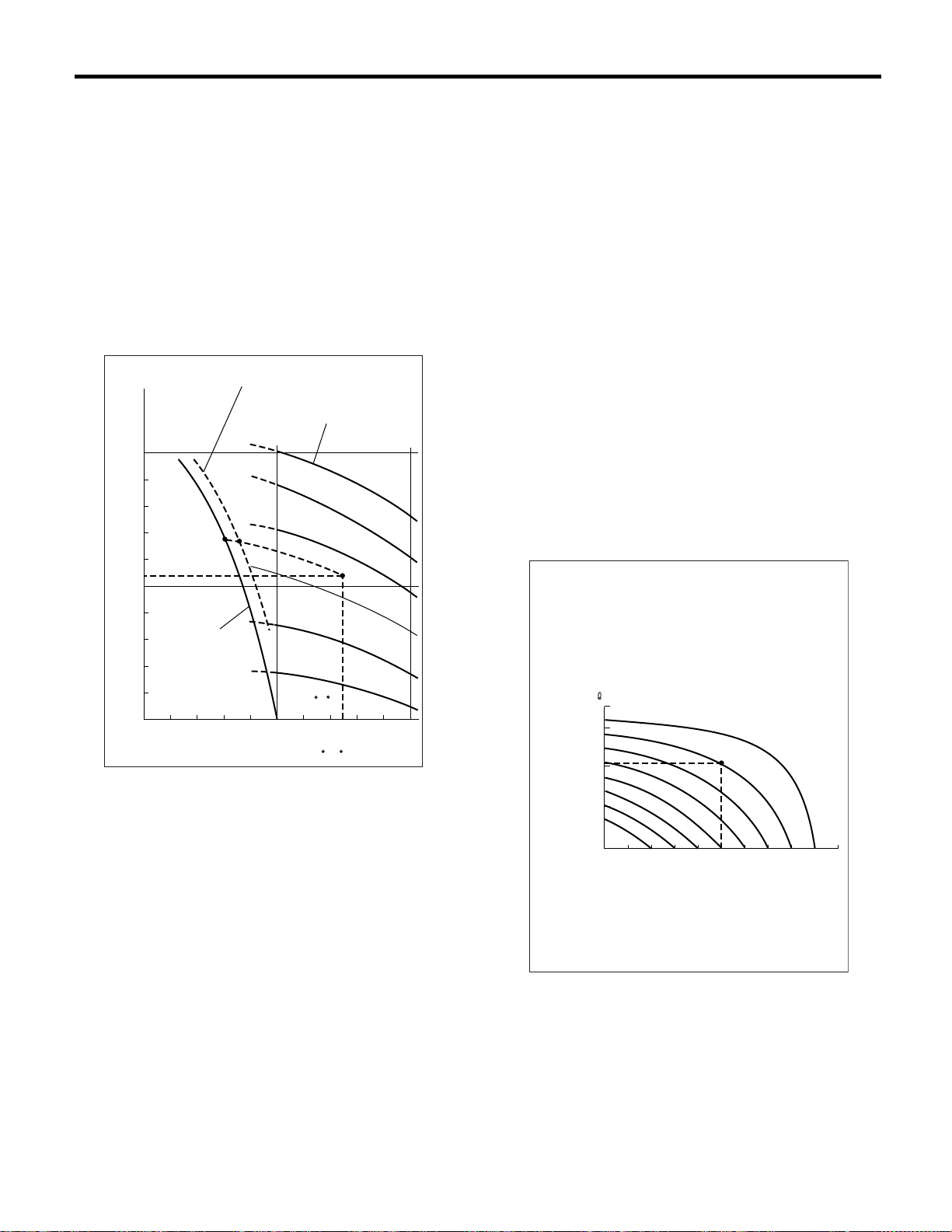
PERIODIC MAINTENANCE SERVICES
Coolant
2. RELATIONSHIP OF SUBARU COOLANT
CONCENTRATION AND FREEZING TEMPERATURE
The concentration and safe operating temperature
of the SUBARU coolant is shown in the diagram.
Measuring the temperature and specific gravity of
the coolant will provide this information.
[Example]
If the coolant temperature is 25°C (77°F) and its
specific gravity is 1.054, the concentration is 35%
(point A), the safe operating temperature is −14°C
(7°F) (point B), and the freezing temperature is
−20°C (−4°F) (point C).
(2)
(3)
1.100
1.090
1.080
(1)
1.070
1.060
1.050
1.040
1.030
1.020
1.010
1.000
(1.054)
-40
-30
(-40) (-22)
C
(4)
-20 -10
(-4)
B
(14)
(32)
(1) Coolant gravity
(2) Safe operating temperature
(3) Concentration of coolant
(4) Freezing temperature
(5) Coolant temperature
25 C
01020304050
(50) (68) (86)
(5)
C
A
(77 F)
( F)
60%
50%
40%
30%
20%
10%
(104) (122)
PM-00025
3. PROCEDURE TO ADJUST THE CONCENTRATION OF THE COOLANT
To adjust the concentration of the coolant according to temperature, find the proper fluid concentration in the above diagram and replace the
necessary amount of coolant with an undiluted solution of SUBARU genuine coolant (concentration
50%).
The amount of coolant that should be replaced can
be determined using the diagram.
[Example]
Assume that the coolant concentration must be increased from 25% to 40%. Find point A, where the
25% line of coolant concentration intersects with
the 40% curve of the necessary coolant concentration, and read the scale on the vertical axis of the
graph at height A. The quantity of coolant to be
drained is 2.12 (2.2 US qt, 1.8 Imp qt). Drain 2.1 2
(2.2 US qt, 1.8 Imp qt) of coolant from the cooling
system and add 2.12 (2.2 US qt, 1.8 Imp qt) of the
undiluted solution of SUBARU coolant.
If a coolant concentration of 50% is needed, drain
all the coolant and refill with the undiluted solution
only.
(1)
(3.2,2.6)
(2.1,1.8)
(1.1,0.9)
(US qt, Imp qt)
3
2
1
10%
0
15%
10
20%
30%
25%
(2)
45%
A
40%
35%
20 30 40 50
(3)
%
PM-22
PM-00026
(1) Quantity of coolant to be drained
(2) Necessary concentration of coolant
(3) Concentration of coolant in vehicle cooling sys-
tem
Page 99
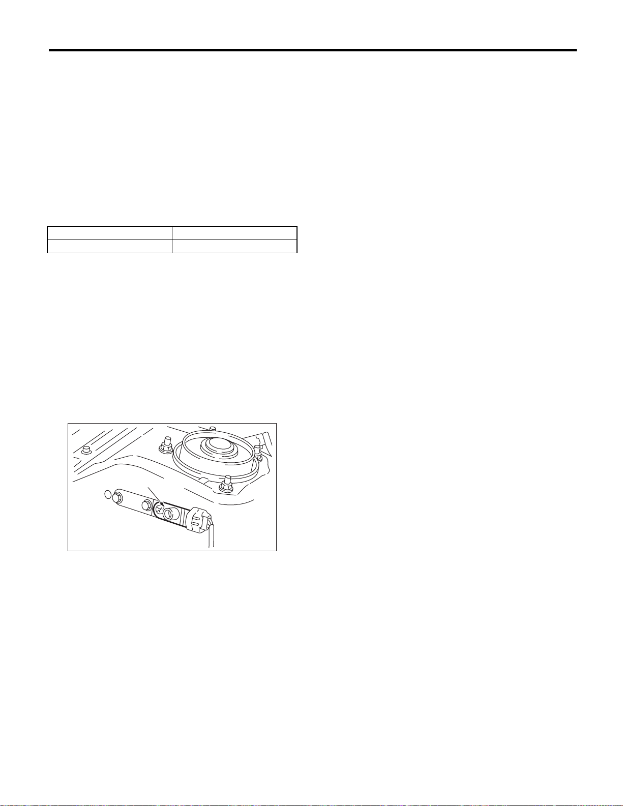
Idle Mixture
13.Idle Mixture
A: INSPECTION AND ADJUSTMENT
1. IDLE MIXTURE
Before measuring the idle mixture, make sure that
the ignition timing and the engine idle speed are
within specifications.
1) Set the gear position at “Neutral” for MT, or “N”
or “P” for AT.
2) Warm up the engine sufficiently until cooling fan
starts to operate.
3) Measure the idle mixture using CO meter.
Engine idle speed CO
700±100 rpm 1.0±0.5%
4) If out of specification, adjust the idle mixture using CO adjusting screw of mass air flow sensor.
5) After adjusting the CO value, check and adjust
the increment coefficient of CO resistor by using
Select Monitor.
(1) Select “Current data display & Save” on the
select monitor.
(2) If out of specified data, adjust the increment
coefficient of CO resistor while rotating the CO
adjusting screw (A).
PERIODIC MAINTENANCE SERVICES
Specified data:
0.28 — 4.22 V
(A)
PM-00146
NOTE:
If driving the vehicle on out of specified data, the
“DTC 49” is indicated in many case.
PM-23
Page 100
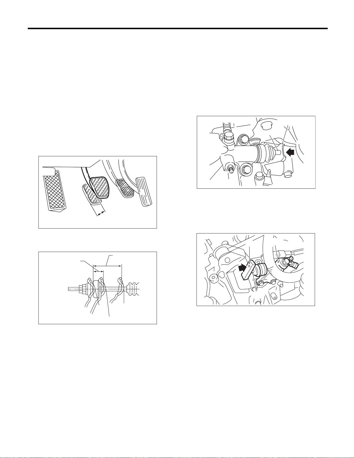
PERIODIC MAINTENANCE SERVICES
Clutch System
14.Clutch System
A: INSPECTION AND ADJUSTMENT
1. MECHANICAL CLUTCH TYPE
1) Inspect the free play of clutch pedal by operating
pedal by hand.
If it is out of the specified value, adjust it by turning
wing nut on engine side of clutch cable at release
fork.
Tightening torque
(Adjusting nut on release fork):
4.4 — 7.4 N·m
(0.45 — 0.75 kgf-m, 3.3 — 5.4 ft-lb)
Standard free play A:
10 — 20 mm (0.39 — 0.79 in)
A
PM-00151
Standard:
80 mm (3.15 in) or more
3) Pedal height
Check that the clutch pedal pad surface is level
with or higher than brake pedal pad surface.
2. HYDRAULIC CLUTCH TYPE
1) Push the release lever to retract the push rod of
the operating cylinder and check if the fluid level in
the clutch reservoir tank rises or not.
NON-TURBO MODEL
(A)
(B)
(C)
(A) Release lever
(B) Push rod
(C) Operating cylinder
TURBO MODEL
PM-00075
Fork lever free play allowance A:
2 — 4 mm (0.08 — 0.16 in)
(1)
A
PM-00152
(1) Full stroke: 25.5 mm (1 in)
2) Pedal-to-floor plate gap in disengaged position.
(1) With the engine idling, pull the parking brake
lever completely.
(2) Slowly depress the clutch pedal while moving shift lever into reverse.
(3) Stop depressing the clutch pedal when
gearshifting is complete. With the clutch pedal in
this position, measure the distance between the
upper side of pedal pad and the lower end of
front panel (intersection of front panel with floor).
Check that the measured value is within the
specification.
(A)
(B)
(A) Release lever
(B) Push rod
(C) Operating cylinder
(C)
PM-00101
2) If the fluid level rises, pedal free play is correct.
3) If the fluid level does not rise, or the push rod
cannot be retracted, adjust the clutch pedal. <Ref.
to CL-40, Clutch Pedal.>
4) Check the fluid level using the scale on the outside of the clutch master cylinder tank (A). If the level is below “MIN” (B), inspect the clutch master
cylinder, operating cylinder and hydraulic line for
fluid leaks. If fluid leaks are found, repair or replace.
If fluid leaks are not found, add clutch fluid to bring
it up to “MAX” (C) of clutch reservoir tank.
PM-24
 Loading...