

Page 1
OnAir 500 Modulo
Digital Mixing Console
Installation and Service Instructions
Page 2

Studer is a registered trade mark of Studer Professional Audio GmbH, Regensdorf
Prepared and edited by Copyright by Studer Professional Audio GmbH
Studer Professional Audio GmbH Printed in the UK
Technical Documentation Order no. 10.27.5091 (Ed. 0805)
Althardstrasse 30
CH-8105 Regensdorf – Switzerland
http://www.studer.ch
Subject to change
Page 3

Safety Information
I
A Safety Information
To reduce the risk of electric shock, do not remove covers. No userserviceable parts inside. Refer servicing to qualified service personnel
(i.e., persons having appropriate technical training and experience necessary to be aware of hazards to which they are exposed in performing a
repair action, and of measures to minimize the danger of themselves).
This symbol alerts the user to the presence of un-insulated dangerous
voltage within the equipment that may be of sufficient magnitude to constitute a risk of electric shock to a person.
This symbol alerts the user to important instructions for operating and
maintenance in this documentation.
Assemblies or sub-assemblies of this product can contain opto-electronic
devices. As long as these devices comply with Class I of laser or LED
products according to EN 60825-1:1994, they will not be expressly
marked on the product. If a special design should be covered by a higher
class of this standard, the device concerned will be marked directly on
the assembly or sub-assembly in accordance with the above standard.
A1 First Aid
In Case of Electric Shock: Separate the person as quickly as possible from the electric power
source:
• By switching off the equipment,
• By unplugging or disconnecting the mains cable, or
• By pushing the person away from the power source, using dry,
insulating material (such as wood or plastic).
• After having suffered an electric shock, always consult a doctor.
Warning! Do not touch the person or his clothing before the power is turned
off, otherwise you stand the risk of suffering an electric shock as
well!
If the Person is Unconscious: • Lay the person down
• Turn him to one side
• Check the pulse
• Reanimate the person if respiration is poor
• Call for a doctor immediately.
CLASS I
LASER PRODUCT
CLASS I
LED PRODUCT
Page 4

Installation/Maintenance/ESD
II
B General Installation Instructions
Please consider besides these general instructions also any product-specific
instructions in the “Installation” chapter of this manual.
B1 Unpacking
Check the equipment for any transport damage. If the unit is mechanically
damaged, if liquids have been spilled or if objects have fallen into the unit,
it must not be connected to the AC power outlet, or it must be immediately
disconnected by unplugging the power cable. Repair must only be per-
formed by trained personnel in accordance with the applicable regulations.
B2 Installation Site
Install the unit in a place where the following conditions are met:
• The temperature and the relative humidity of the environment must be
within the specified limits during operation of the unit. Relevant values
are the ones at the air inlets of the unit.
• Condensation must be avoided. If the unit is installed in a location with
large variation of ambient temperature (e.g. in an OB-van), appropriate
precautions must be taken before and after operation (for details on this
subject, refer to Appendix 1).
• Unobstructed air flow is essential for proper operation. Air vents of the
unit are a functional part of the design and must not be blocked in any
way during operation (e.g. by objects placed upon them, placement of
the unit on a soft surface, or installation of the unit within a rack or
piece of furniture).
• The unit must not be heated up by external sources of heat radiation
(sunlight, spot lights).
B3 Earthing and Power Supply
Earthing of units with mains supply (class I equipment) is performed via
the protective earth (PE) conductor integrated in the mains cable. Units
with battery operation (< 60 V, class III equipment) must be earthed separately.
Earthing the unit is one of the measures for protection against electrical
shock hazard (dangerous body currents). Hazardous voltage may not only
be caused by a defective power supply insulation, but may also be introduced by the connected audio or control cables.
If the unit is installed with one or several external connections, its earthing
must be provided during operation as well as while the unit is not operated.
If the earthing connection can be interrupted, for example, by unplugging
the mains plug of an external power supply unit, an additional, permanent
earthing connection must be installed using the provided earth terminal.
Avoid ground loops (hum loops) by keeping the loop surface as small as
possible (by consequently guiding the earth conductors in a narrow, parallel way), and reduce the noise current flowing through the loop by inserting
an additional impedance (common-mode choke).
Page 5
ESD/Repair
III
Class I Equipment (Mains Operation)
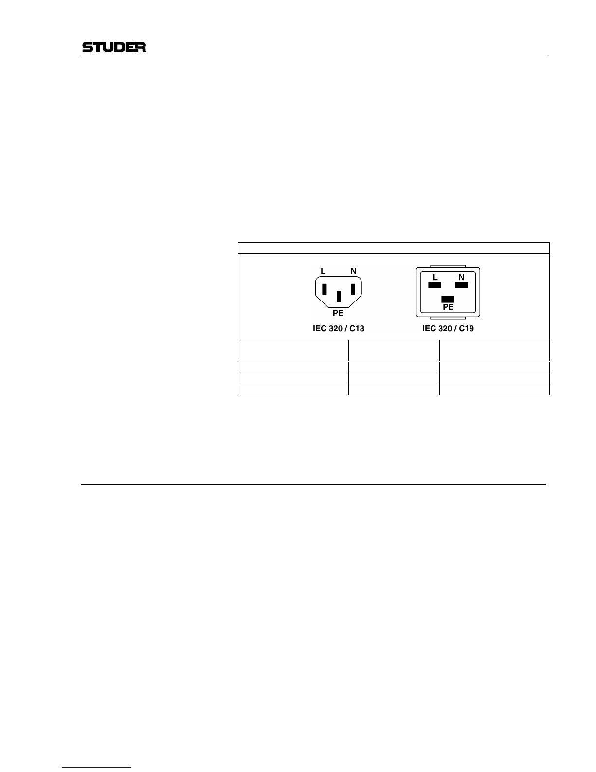
Should the equipment be delivered without a matching mains cable, the
latter has to be prepared by a trained person using the attached female plug
(IEC320/C13 or IEC320/C19) with respect to the applicable regulations in
your country.
Before connecting the equipment to the AC power outlet, check that the
local line voltage matches the equipment rating (voltage, frequency) within
the admissible tolerance. The equipment fuses must be rated in accordance
with the specifications on the equipment.
Equipment supplied with a 3-pole appliance inlet (protection conforming to
class I equipment) must be connected to a 3-pole AC power outlet so that
the equipment cabinet is connected to the protective earth.
For information on mains cable strain relief please refer to Appendix 2.
Female Plugs (IEC320), Front-Side View:
European Standard
(CENELEC)
North American Standard
(NAS)
Brown L (Live) Black
Blue N (Neutral) White
Green/Yellow PE (Protective Earth) Green (or Green/Yellow)
Class III Equipment (Battery Operation up to 60 VDC)
Equipment of this protection class must be earthed using the provided earth
terminal, if one or more external signals are connected to the unit (see explanation at the beginning of this paragraph).
B4 Electromagnetic Compatibility (EMC)
The unit conforms to the protection requirements relevant to electromagnetic phenomena that are listed in guidelines 89/336/EC and FCC, part 15.
• The electromagnetic interference generated by the unit is limited in such
a way that other equipment and systems can be operated normally.
• The unit is adequately protected against electromagnetic interference so
that it can operate properly.
The unit has been tested and conforms to the EMC standards of the specified electromagnetic environment, as listed in the following declaration.
The limits of these standards ensure protection of the environment and corresponding noise immunity of the equipment with appropriate probability.
However, a professional installation and integration within the system are
imperative prerequisites for operation without EMC problems.
For this purpose, the following measures must be followed:
• Install the equipment in accordance with the operating instructions. Use
the supplied accessories.
• In the system and in the vicinity where the equipment is installed, use
only components (systems, equipment) that also fulfill the EMC standards for the given environment.
• Use a system grounding concept that satisfies the safety requirements
(class I equipment must be connected with a protective ground conduc-
Page 6

Installation/Maintenance/ESD
IV
tor) and that also takes into consideration the EMC requirements. When
deciding between radial, surface, or combined grounding, the advantages and disadvantages should be carefully evaluated in each case.
• Use shielded cables where shielding is specified. The connection of the
shield to the corresponding connector terminal or housing should have a
large surface and be corrosion-proof. Please note that a cable shield
connected only single-ended can act as a transmitting or receiving antenna within the corresponding frequency range.
• Avoid ground loops or reduce their adverse effects by keeping the loop
surface as small as possible, and reduce the noise current flowing
through the loop by inserting an additional impedance (e.g. commonmode choke).
• Reduce electrostatic discharge (ESD) of persons by installing an appropriate floor covering (e.g. a carpet with permanent electrostatic filaments) and by keeping the relative humidity above 30%. Further measures (e.g. conducting floor) are usually unnecessary and only effective if
used together with corresponding personal equipment.
• When using equipment with touch-sensitive operator controls, please
take care that the surrounding building structure allows for sufficient
capacitive coupling of the operator. This coupling can be improved by
an additional, conducting surface in the operator’s area, connected to the
equipment housing (e.g. metal foil underneath the floor covering, carpet
with conductive backing).
C Maintenance
All air vents and openings for operating elements (faders, rotary knobs)
must be checked on a regular basis, and cleaned in case of dust accumulation. For cleaning, a soft paint-brush or a vacuum cleaner is recommended.
Cleaning the surfaces of the unit is performed with a soft, dry cloth or a
soft brush.
Persistent contamination can be treated with a cloth that is slightly humidified with a mild cleaning solution (soap-suds).
For cleaning display windows, commercially available computer/TV
screen cleaners are suited. Use only a slightly damp (never wet) cloth.
Never use any solvents for cleaning the exterior of the unit! Liquids must
never be sprayed or poured on directly!
For equipment-specific maintenance information please refer to the corresponding chapter in the Operating and Service Instructions manuals.
D Electrostatic Discharge during Maintenance and Repair
Caution: Observe the precautions for handling devices sensitive to electrostatic dis-
charge!
Many semiconductor components are sensitive to electrostatic discharge
(ESD). The life-span of assemblies containing such components can be
drastically reduced by improper handling during maintenance and repair
work. Please observe the following rules when handling ESD sensitive
components:
• ESD sensitive components should only be stored and transported in the
packing material specifically provided for this purpose.
• When performing a repair by replacing complete assemblies, the removed assembly must be sent back to the supplier in the same packing
Page 7

ESD/Repair
V
material in which the replacement assembly was shipped. If this should
not be the case, any claim for a possible refund will be null and void.
• Unpacked ESD sensitive components should only be handled in ESD
protected areas (EPA, e.g. area for field service, repair or service bench)
and only be touched by persons who wear a wristlet that is connected to
the ground potential of the repair or service bench by a series resistor.
The equipment to be repaired or serviced as well as all tools and electrically semi-conducting work, storage, and floor mats should also be connected to this ground potential.
• The terminals of ESD sensitive components must not come in uncontrolled contact with electrostatically chargeable (voltage puncture) or
metallic surfaces (discharge shock hazard).
• To prevent undefined transient stress of the components and possible
damage due to inadmissible voltages or compensation currents, electrical connections should only be established or separated when the
equipment is switched off and after any capacitor charges have decayed.
E Repair
Removal of housing parts, shields, etc. exposes energized parts. For this
reason the following precautions must be observed:
• Maintenance may only be performed by trained personnel in accordance
with the applicable regulations.
• The equipment must be switched off and disconnected from the AC
power outlet before any housing parts are removed.
• Even if the equipment is disconnected from the power outlet, parts with
hazardous charges (e.g. capacitors, picture tubes) must not be touched
until they have been properly discharged. Do not touch hot components
(power semiconductors, heat sinks, etc.) before they have cooled off.
• If maintenance is performed on a unit that is opened and switched on, no
un-insulated circuit components and metallic semiconductor housings
must be touched, neither with your bare hands nor with un-insulated
tools.
Certain components pose additional hazards:
• Explosion hazard from lithium batteries, electrolytic capacitors and
power semiconductors (watch the component’s polarity. Do not short
battery terminals. Replace batteries only by the same type).
• Implosion hazard from evacuated display units.
• Radiation hazard from laser units (non-ionizing), picture tubes (ionizing).
• Caustic effect of display units (LCD) and components containing liquid
electrolyte.
Such components should only be handled by trained personnel who are
properly protected (e.g. safety goggles, gloves).
Page 8
Repair/Disposal
VI
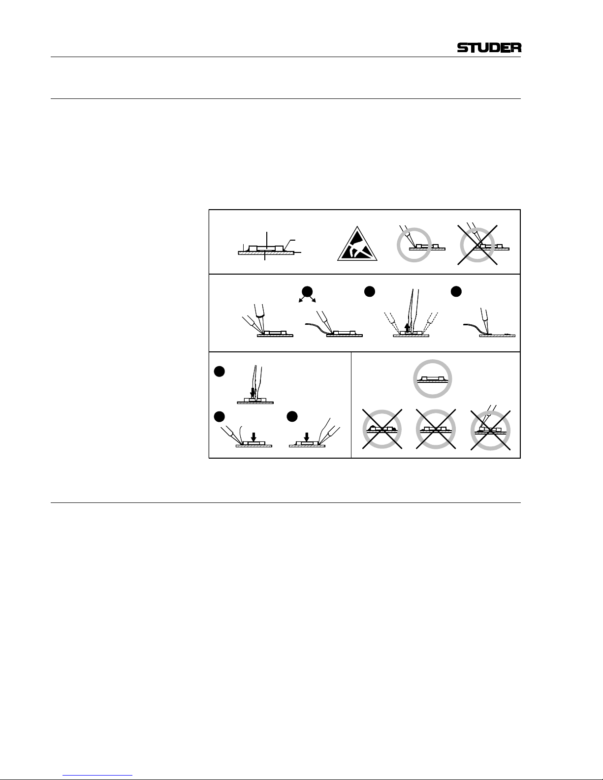
E1 SMD Components
Studer has no commercially available SMD components in stock for service purposes. For repair, the corresponding devices have to be purchased
locally. The specifications of special components can be found in the service manual.
SMD components should only be replaced by skilled specialists using appropriate tools. No warranty claims will be accepted for circuit boards that
have been damaged. Proper and improper SMD soldering joints are illustrated below.
F Disposal
Disposal of Packing Materials The packing materials have been selected with environmental and disposal
issues in mind. All packing material can be recycled. Recycling packing
saves raw materials and reduces the volume of waste.
If you need to dispose of the transport packing materials, please try to use
recyclable means.
Disposal of Used Equipment Used equipment contains valuable raw materials as well as materials that
must be disposed of professionally. Please return your used equipment via
an authorized specialist dealer or via the public waste disposal system, ensuring any material that can be recycled is.
Please take care that your used equipment cannot be abused. To avoid
abuse, delete sensitive data from any data storage media. After having disconnected your used equipment from the mains supply, make sure that the
mains connector and the mains cable are made useless.
32
Dismounting
Mounting
Examples
Solder
SMD
Component
Copper
Track
Adhesive
Soldering Iron
Desoldering
Iron
Desolder
Wick
Heat and Remove Cleaning
Solder
Ø 0.5...0.8 mm
Heating Time < 3 s per Side
Soldering
Iron
Desolder
Wick
1
3
2
1
PCB
Page 9

Conformity
VII
G Declarations of Conformity
G1 Class A Equipment - FCC Notice
This equipment has been tested and found to comply with the limits for a
Class A digital device, pursuant to Part 15 of the FCC Rules. These limits
are designed to provide a reasonable protection against harmful interference when the equipment is operated in a commercial environment. This
equipment generates, uses, and can radiate radio frequency energy and, if
not installed and used in accordance with the instruction manual, may
cause harmful interference to radio communications. Operation of this
equipment in a residential area is likely to cause harmful interference, in
which case the user will be required to correct the interference at his own
expense.
Caution: Any changes or modifications not expressly approved by the manufacturer
vant information in this manual.
G2 CE Declaration of Conformity
We,
Studer Professional Audio GmbH,
CH-8105 Regensdorf,
declare under our sole responsibility that the product
Studer OnAir 500 Modulo, Digital Mixing Console
(starting with serial no. 1059)
to which this declaration relates, according to following regulations of EU
directives and amendments
• Low Voltage (LVD):
73/23/EEC + 93/68/EEC
• Electromagnetic Compatibility (EMC):
89/336/EEC + 92/31/EEC + 93/68/EEC
is in conformity with the following standards or normative documents:
• Safety:
EN 60950-1:2001 (Class I equipment)
• Safety of laser products:
EN 60825-1:2004 + A11 + A2, EN60825-2:2000
• EMC:
EN 55103-1/-2:1996, electromagnetic environments E2 and E4.
Regensdorf, October 26, 2004
B. Hochstrasser, President M. Lienert, Manager R&D
Page 10

Appendix
VIII
Appendix 1: Air Temperature and Humidity
General
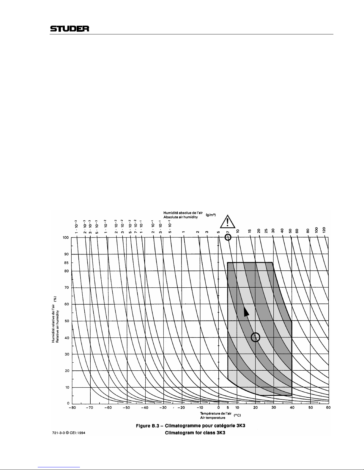
Normal operation of the unit or system is warranted under the following
ambient conditions defined by EN 60721-3-3, set IE32, value 3K3.
This standard consists of an extensive catalogue of parameters, the most
important of which are: ambient temperature +5...+40 °C, relative humidity
5...85% (i.e., no formation of condensation or ice); absolute humidity
1...25 g/m³; rate of temperature change < 0.5 °C/min. These parameters are
dealt with in the following paragraphs.
Under these conditions the unit or system starts and works without any
problem. Beyond these specifications, possible problems are described in
the following paragraphs.
Ambient Temperature
Units and systems by Studer are generally designed for an ambient temperature range (i.e. temperature of the incoming air) of +5...+40 °C. When
rack mounting the units, the intended air flow and herewith adequate cooling must be provided. The following facts must be considered:
• The admissible ambient temperature range for operation of the semiconductor components is 0 °C to +70 °C (commercial temperature range
for operation).
• The air flow through the installation must provide that the outgoing air
is always cooler than 70 °C.
• Average heat increase of the cooling air shall be about 20 K, allowing
for an additional maximum 10 K increase at the hot components.
• In order to dissipate 1 kW with this admissible average heat increase, an
air flow of 2.65 m³/min is required.
Example: A rack dissipating P = 800 W requires an air flow of 0.8 * 2.65 m³/min
which corresponds to 2.12 m³/min.
• If the cooling function of the installation must be monitored (e.g. for fan
failure or illumination with spot lamps), the outgoing air temperature
must be measured directly above the modules at several places within
the rack. The trigger temperature of the sensors should be 65 to 70 °C.
Frost and Dew
The unsealed system parts (connector areas and semiconductor pins) allow
for a minute formation of ice or frost. However, formation of dew visible
with the naked eye will already lead to malfunctions. In practice, reliable
operation can be expected in a temperature range above –15 °C, if the following general rule is considered for putting the cold system into operation:
If the air within the system is cooled down, the relative humidity rises. If it
reaches 100%, condensation will arise, usually in the boundary layer between the air and a cooler surface, together with formation of ice or dew at
sensitive areas of the system (contacts, IC pins, etc.). Once internal condensation occurs, trouble-free operation cannot be guaranteed, independent
of temperature.
Before putting into operation, the system must be checked for internal formation of condensation or ice. Only with a minute formation of ice, direct
Page 11
Appendix
IX
evaporation (sublimation) may be expected; otherwise the system must be
heated and dried while switched off.
A system without visible internal formation of ice or condensation should
be heated up with its own heat dissipation, as homogeneously (and subsequently as slow) as possible; the ambient temperature should then always
be lower than the one of the outgoing air.
If it is absolutely necessary to operate the cold system immediately within
warm ambient air, this air must be dehydrated. In such a case, the absolute
humidity must be so low that the relative humidity, related to the coldest
system surface, always remains below 100%.
Ensure that the enclosed air is as dry as possible when powering off (i.e.
before switching off in winter, aerate the room with cold, dry air, and remove humid objects as clothes from the room).
These relationships are visible from the following climatogram. For a controlled procedure, thermometer and hygrometer as well as a thermometer
within the system will be required.
Example 1: An OB-van having an internal temperature of 20 °C and relative humidity
of 40% is switched off in the evening. If temperature falls below +5 °C,
dew or ice will be forming.
Example 2: An OB-van is heated up in the morning with air of 20 °C and a relative
humidity of 40%. On all parts being cooler than +5 °C, dew or ice will be
forming.
Page 12
Appendix
X
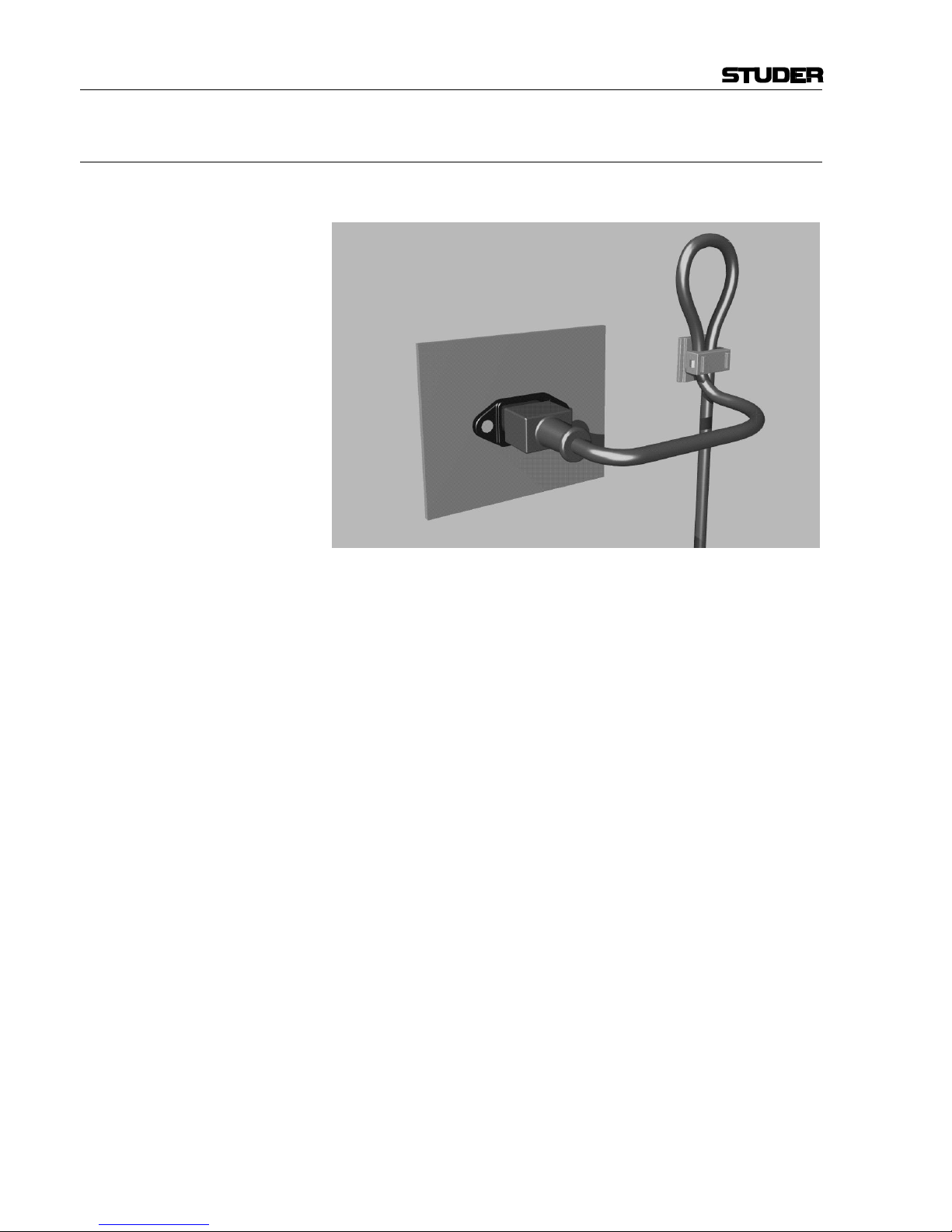
Appendix 2: Mains Connector Strain Relief
For anchoring connectors without a mechanical lock (e.g. IEC mains connectors), we recommend the following arrangement:
Procedure: The cable clamp shipped with your unit is auto-adhesive. For mounting
please follow the rules below:
• The surface to be adhered to must be clean, dry, and free from grease,
oil, or other contaminants. Recommended application temperature range
is +20...+40 °C.
• Remove the plastic protective backing from the rear side of the clamp
and apply it firmly to the surface at the desired position. Allow as much
time as possible for curing. The bond continues to develop for as long as
24 hours.
• For improved stability, the clamp should be fixed with a screw. For this
purpose, a self-tapping screw and an M4 bolt and nut are included.
• Place the cable into the clamp as shown in the illustration above and
firmly press down the internal top cover until the cable is fixed.
Page 13

Appendix
XI
Appendix 3: Software License
Use of the software is subject to the Studer Professional Audio Software
License Agreement set forth below. Using the software indicates your acceptance of this license agreement. If you do not accept these license terms,
you are not authorized to use this software.
Under the condition and within the scope of the following Terms and Conditions, Studer Professional Audio GmbH (hereinafter “Studer”) grants the
right to use programs developed by Studer as well as those of third parties
which have been installed by Studer on or within its products. References
to the license programs shall be references to the newest release of a license program installed at the Customer’s site.
Programs Covered by the Agreement
License Programs of Studer The following Terms and Conditions grant the right to use all programs of
Studer that are part of the System and/or its options at the time of its delivery to the Customer, as well as the installation software on the original data
disk and the accompanying documentation (“License Material”). In this
Agreement the word “Programs” shall have the meaning of programs and
data written in machine code.
Using the software indicates your acceptance of this license agreement. If
you do not accept these license terms, you are not authorized to use this
software.
Programs of Third Parties Programs of third parties are all programs which constitute part of the
System and/or its options at the time of delivery to the Customer but have
not been developed by Studer. The following conditions are applicable to
programs of third parties:
• The right to use third parties’ programs is governed by the License
Agreement attached hereto (if applicable), which is an integral part of
this Agreement. The Customer shall sign any and all License Agreements for all further programs of third parties installed on the system.
The Customer shall be deemed to have received all License Agreements
upon delivery of the system and/or its options.
• Studer shall accept no responsibility or liability for, and gives no warranties (express or implied) as to the programs of third parties. The
Customer waives any and all claims versus Studer for any consequential
damages, which might occur due to defects of these programs.
Right of Use
Principle Studer grants the Customer the non-exclusive right to use the License Ma-
terial in one copy on the system and/or its options as laid down by the
Sales Agreement concluded between the parties and all Terms and Conditions which shall be deemed to form and be read and construed as part of
the Sales Agreement. This right is assignable according to the “Assignability” paragraph hereinafter.
Customized Configurations The Customer is not entitled to alter or develop further the License Mate-
rial except within the expressly permitted configuration possibilities given
by the software installed on the system or elsewhere. All altered programs,
including but not limited to the products altered within the permitted configuration possibilities, are covered by this License Agreement.
Page 14

Appendix
XII
Reverse Engineering Reverse engineering is only permitted with the express consent of Studer.
The consent of Studer can be obtained but is not limited to the case in
which the interface-software can not be provided by Studer. In any case
Studer has to be informed immediately upon complete or partial reverse
engineering.
Copying the License Material The Customer is entitled to make one copy of all or parts of the License
Material as is necessary for the use according to this Agreement, namely
for backup purposes. The Customer shall apply the copyright of Studer
found on the License Material onto all copies made by him. Records shall
be kept by the Customer regarding the amount of copies made and their
place of keeping. The responsibility for the original program and all copies
made lies with the Customer. Studer is entitled to check these records on
first request. Copies not needed anymore have to be destroyed immediately.
Disclosure of License Material The License Material is a business secret of Studer. The Customer shall not
hand out or in any way give access to parts or the complete License Material to third parties nor to publish any part of the License Material without
prior written consent of Studer. The Customer shall protect the License
Material and any copies made according to the paragraph above by appropriate defense measures against unauthorized access. This obligation of
non-disclosure is a perpetual obligation.
Third parties are entitled to have access to the License Material if they use
the License Material at the Customer’s site in compliance with this Agreement.
Under no circumstance are third parties entitled to have access to the installation software on the original data media. The Customer shall safeguard the original data media accordingly.
Assignability The rights granted to the Customer according to this License Agreement
shall only be assignable to a third party together with the transfer of the
system and/or its options and after the prior written consent of Studer.
Rights to License Material
With the exception of the right of use granted by this License Agreement
all proprietary rights to the License Material, especially the ownership and
the intellectual property rights (such as but not limited to patents and copyright) remain with Studer even if alterations, customized changes or
amendments have been made to the License Material.
Studer’s proprietary rights are acknowledged by the Customer. The Customer shall undertake no infringements and make no claims of any patent,
registered design, copyright, trade mark or trade name, or other intellectual
property right.
Warranty, Disclaimer, and Liability
For all issues not covered herewithin, refer to the “General Terms and
Conditions of Sales and Delivery” being part of the sales contract.
Page 15

OnAir 500 Modulo Digital Mixing Console
Installation Instructions 1Date printed: 25.08.05
CONTENTS
1 Introduction ........................................................................................................................................................................2
2 General ................................................................................................................................................................................3
2.1 Utilization for the Purpose Intended .............................................................................................................................. 3
2.2 First Steps....................................................................................................................................................................... 3
2.2.1 Unpacking and Inspection.....................................................................................................................................3
2.2.2 Installation.............................................................................................................................................................3
2.2.3 Adjustments, Repair, Cleaning............................................................................................................................. 4
3 Hardware.............................................................................................................................................................................5
3.1 Fader Module................................................................................................................................................................. 5
3.2 Master Module............................................................................................................................................................... 5
3.3 19” Processor Frame ...................................................................................................................................................... 6
3.4 Meter Module................................................................................................................................................................. 7
3.5 Differences from the OnAir 500 Fixed-Frame Version ................................................................................................. 7
4 Wiring ..................................................................................................................................................................................8
4.1 Processor Frame Wiring.................................................................................................................................................8
4.2 System Wiring................................................................................................................................................................9
4.3 Connector Pin Assignments...........................................................................................................................................9
4.4 Connector Panel........................................................................................................................................................... 10
5 Upgrade from 6- to 12-Fader Version ............................................................................................................................. 11
6 Diagrams............................................................................................................................................................................12
Page 16
OnAir 500 Modulo Digital Mixing Console
2 Installation Instructions Date printed: 23.11.04
1 INTRODUCTION
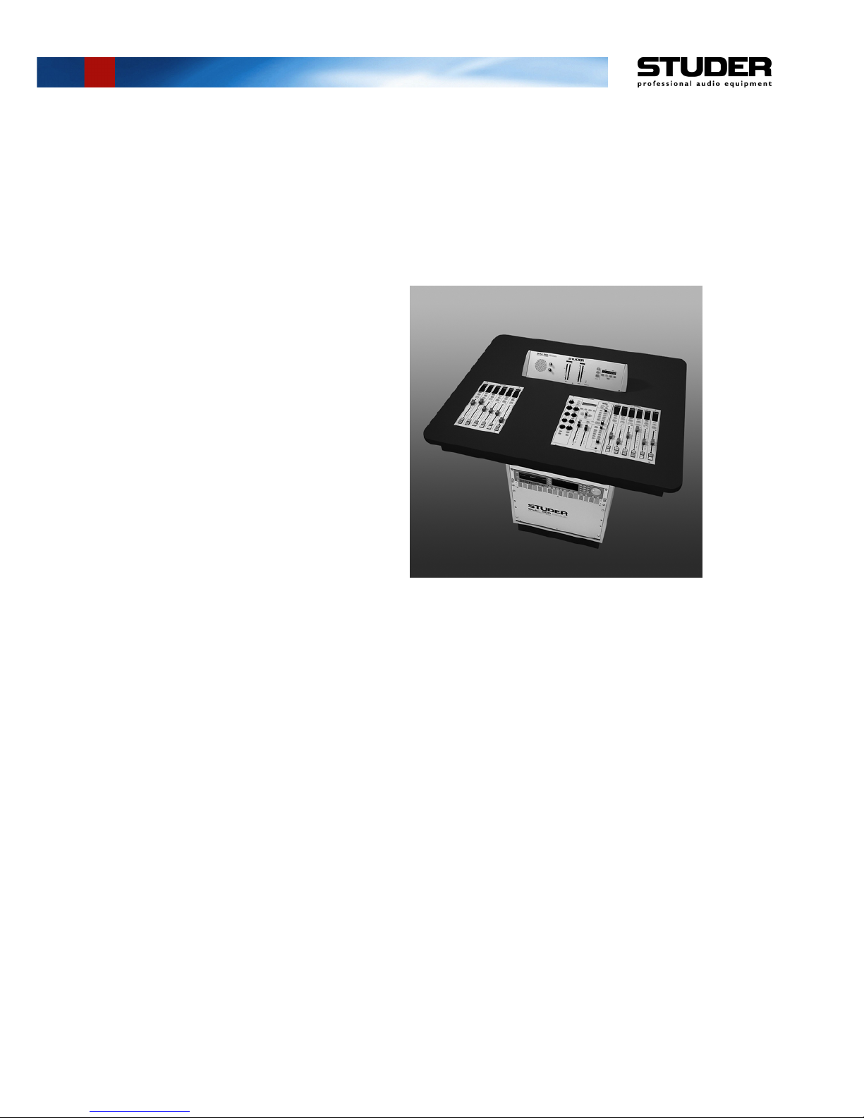
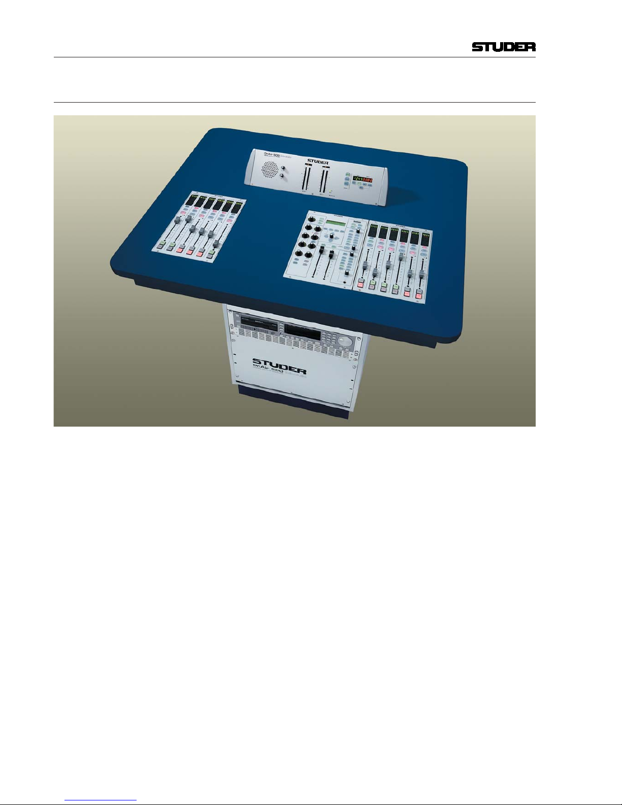
The OnAir 500 Modulo is virtually identical with Studer’s well-known OnAir
500 digital mixing console, except that it adds a new degree in fl exibility
due to its modular surface design. This allows the studio designer to arrange
the desk components to the user’s convenience, and to distance the I/Os and
processor from the desk if desired. In addition, a 12-fader version is available
as well.
The technical specifi cations, confi gurations and options as well as the op-
eration are the same as with the standard Studer OnAir 500 digital mixing
console. For operation and/or service, please consult the respective manuals.
An OnAir 500 operating manual is shipped together with each OnAir 500
Modulo console.
This manual describes only the differences to the standard Studer OnAir 500
console.
The picture above shows a typical OnAir 500 Modulo confi guration, installed
in a compact custom table.
Page 17

OnAir 500 Modulo Digital Mixing Console
Installation Instructions 3Date printed: 23.11.04
2 GENERAL
2.1 Utilization for the Purpose Intended
The OnAir 500 Modulo mixing console is intended for professional use.
It is presumed that the unit is operated only by trained personnel. Servicing
is reserved to skilled technicians.
The electrical connections may be connected only to the voltages and signals
designated in this manual or in the respective OnAir 500 manuals.
2.2 First Steps
2.2.1 Unpacking and Inspection
Your new mixing console is shipped in a special packing which protects the
units against mechanical shock during transit. Care should be exercised when
unpacking so that the surfaces do not get marred.
Check the condition of the equipment for signs of shipping damage. If there
should be any complaints you should immediately notify the forwarding agent
and your nearest Studer distributor.
Please retain the original packing material because it offers the best protection
in case your equipment ever needs to be transported.
2.2.2 Installation
General Precautions: Do not use the unit in conditions of excessive heat or cold, near any source
of moisture, in excessively humid environments, or in positions where it is
likely to be subjected to vibration or dust. The ambient temperature range for
normal operation of the unit is +5...+40° C.
When installing the processor frame, free air fl ow has to be assured. If the
rack is closed at the top and/or the bottom, the 1U air vent panels shipped
with the unit must be installed above and/or below the processor frame; refer
to the drawing in chapter 3.3 for details.
Primary Voltage: The power supply unit is auto-ranging; it can be used for mains voltages in
a range of 100 to 240 VAC, 50 to 60 Hz.
Power Connection : The attached female IEC 320/C13 mains cable socket has to be connected
to an appropriate mains cable by a trained technician, respecting your local
regulations. Refer to the “Installation, Operation, and Waste Disposal” chapter at the beginning of this manual.
In case of 24 V
DC
operation, use an appropriate connection to the external DC
supply unit or battery, equipped on one end with the attached 10-pole cable
socket.
For DC operation it is mandatory that a UL approved, external fuse is in
series with one of the supply lines (T 5 A H 250 V UL/CSA).
For pin assignment of the 24 VDC connector please refer to chapter 12.2.5 of
the OnAir 500 Operating Instructions manual.
Please check your DC supply cable for correct polarity before connecting it
to the console.
Page 18

OnAir 500 Modulo Digital Mixing Console
4 Installation Instructions Date printed: 23.11.04
DC Operation : The console can be operated from a 24 VDC source (battery, external supply
unit, UPS) through the respective 24 V
DC
connector provided on the rear
panel.
For DC operation it is mandatory that a UL approved, external fuse is in
series with one of the supply lines (T 5 A H 250 V UL/CSA).
The power switch next to the power inlet only switches the mains voltage; for
DC operation, an external power switch has to be foreseen by the installer.
Earthing : This equipment must be earthed, due to the mains input fi lter network be ing
connected to the mains earth . Also in case of DC operation, earthing of the
unit is mandatory.
Some consideration must be given to the earthing arrangement of the sy stem,
at the center of which is the processor frame. The processor frame is earthed
to the mains earth via the power supply and/or the dedicated earth connection
bolt. Ground loops may occur where signal processing equip ment, patched
to the console, has its signal earth commoned to the equip ment chassis.
Wiring: Please note that the connecting cables from the processor frame to the in-
dividual modules (see chapter 4.2) must by no means be connected or unplugged while power is on - no hot-plugging is supported by the OnAir 500
Modulo!
2.2.3 Adjustments, Repair, Cleaning
Danger: All internal adjustments as well as repair work on this product must be per-
formed by trained technicians!
Replacing the Supply Unit: The primary fuse is located within the power supply module and cannot be
changed. In case of failure, the complete power supply unit must be replaced.
Please ask your nearest Studer representative.
Cleaning: Do not use any liquids to clean the exterior of the unit. A soft, dry cloth or
brush will usually do.
For cleaning the display windows, most of the commercially available win-
dow or computer/TV screen cleaners are suited. Use only a slightly damp
(never wet) cloth. Never use any solvent!
Page 19

OnAir 500 Modulo Digital Mixing Console
Installation Instructions 5Date printed: 23.11.04
3 HARDWARE
3.1 Fader Module
The fader module includes six channel faders with ON, OFF and CUE, SE-
LECT and INPUT 2 keys. A four-character display at the top of the channel
status window indicates the source name. A second source can be selected by
the INPUT 2 key directly below the status window. In this window also bus
assignments, EQ or dynamics being active and cleanfeed and talkback status
are displayed. The SELECT key assigns this respective channel to the master
module. The console can be equipped with one or two fader modules, giving
a total of 6 or 12 faders. (For a dimensions drawing refer to chapter 3.2)
Module weight: 1.8 kg
3.2 Master Module
The master module provides two stereo master faders for the main buses,
which can also be de-assigned if desired, AUX send controls and EQ, dynamics and high-pass fi lter controls. In addition, an LC display gives access to
menus for setting up the console dynamics, storing presets and confi guring
the console. Direct access to the input router is also given by these menus.
Comprehensive monitoring and talkback facilities for the control room and
one studio are provided in the right-hand part of the master module. Also a
CR headphones jack socket is located there.
Module weight: 1.7 kg
cut 197 mm
196.3 mm
312.3 mm 56 mm
cut 197 mm
196.3 mm
312.3 mm
cut 313 mm
56 mm
Fader ModuleMaster Module
Page 20

OnAir 500 Modulo Digital Mixing Console
6 Installation Instructions Date printed: 23.11.04
3.3 19” Processor Frame
The 19” processor frame includes the DSP and the control CPU, the input
and output electronics and the power supply. Each desk module is connected
to the 19” processor frame via a dedicated cable, except the meter module
which is connected directly to the master module.
Processor frame weight: approx. 12 kg, depending on version
(Left: rear view of a processor frame for a 12-fader OnAir 500 Modulo con-
sole).
Redundant Power Supply Option: In contrast to the OnAir 500 fi xed-frame version, a second primary power
supply unit can be factory-installed within the OnAir 500 Modulo’s 19”
processor frame (order no. 1.942.458.00). A second mains inlet will then be
provided at the frame’s rear panel, in addition to the 24 VDC connector.
482.6 mm (19")
399.2 mm (9 U)
310.3 mm (7 U)
380 mm95 mm*
* add approx. 95...100 mm for audio connectors
Page 21

OnAir 500 Modulo Digital Mixing Console
Installation Instructions 7Date printed: 23.11.04
3.4 Meter Module
The meter module has two 30-LED stereo bargraph meters,
each with a phase correlation indicator, in the center. On
the right are two digital timers which can be controlled by
adjacent keys or from selected fader channels, and on the
left of the meters is the cue speaker and its controls. As the
OnAir 500 Modulo is available with an optional fi rst-level
power supply redundancy feature, an indicator on the front panel of the meter
module signals the correct functioning of the power supplies or the failure
of one of them. In addition, the console can also be operated by any external
24 V
DC
source such as a battery.
Module weight: 1.9 kg
3.5 Differences from the OnAir 500 Fixed-Frame Version
Most of the OnAir 500 Modulo’s electronics assemblies are identical with the
ones of the OnAir 500 fi xed-frame version, with the following exceptions:
Diagrams of the new and the additional assemblies listed above are given in
chapter 5.
12-Fader Version: The OnAir 500 Modulo 12-fader version has a second Dual SPE Module PCB
1.942.486 plugged to the Master Backplane PCB, also refer to the diagram
in chapter 4.1. In addition, there is a second Input Plug-In Unit in the upper
part of the processor frame, consisting of Mic Input Unit, Analog Input Unit,
and AES-S/PDIF Unit.
Please note that there is a minor difference in wiring between the 6-fader and
the 12-fader versions - refer to the illustration in chapter 4.1.
99 mm
46 mm
52°
443.5 mm
490 mm
cut 444 mm
91.3 mm
cut 92 mm
Description
Replaced
Assembly
New Assembly
Additional
Assembly
24 V Power Supply Unit (89.20.2011) 89.20.2015 –
Power Supply PCB (1.942.470) 1.942.471 –
Master Backplane PCB (1.942.483) 1.942.489 –
Extension Backplane PCB – – 1.942.454
Backplane Modulo PCB (line driver IF in Processor Frame) – – 1.942.472
Input Interface PCB (line driver IF in Fader Module) – – 1.942.473
Master Interface PCB (line driver IF in Master Module) – – 1.942.474
Level Meter Interface PCB (line driver IF in Meter Module) – – 1.942.477
Page 22

OnAir 500 Modulo Digital Mixing Console
8 Installation Instructions Date printed: 23.11.04
4 WIRING
Please note that the connecting cables from the processor frame to the in-
dividual modules (see chapter 4.2) must by no means be connected or unplugged while power is on – no hot-plugging is supported by the OnAir 500
Modulo!
The 15- and 25-pin connecting cables all are pin-to-pin connections with one
male and one female D-type connector. They are available in different lengths
and must, therefore, be ordered separately; refer to the table below.
4.1 Processor Frame Wiring
Application Type Length Order no.
2 m 1.942.456.25
Connection from the Processor Frame to the Fader Modules 15-pin 10 m 1.942.456.26
30 m 1.942.456.27
Connection from the Processor Frame to the Master Module; 2 m 1.942.456.35
connection from the Master Module to the Meter Module (please
25-pin 10 m 1.942.456.36
note that usually a 2 m cable is sufficient for this connection)
30 m 1.942.456.37
1 2* 3 4* 5
MASTER NOTE:
This PCB is located behind
the rear panel of the Processor Frame and not visible in the diagram below.
Cables 1...6 correspond to
the ones in the diagram
below.
* IMPORTANT: This illustration shows the internal wiring of a 12-fader version. In 6-fader versions, the cables no. 2 and 4 are swapped.
** Used for 12-fader version only.
FADER 1FADER 2
6
Master Backplane PCB
1.942.489
2*
3
4*
1
5
6
Ext. Backplane PCB
1.942.454
Lexi-Chip PCB 1.942.484
Dual SPE Module PCB 1.942.486
Dual SPE Module PCB 1.942.486**
SPE Module PCB 1.942.485
(see Detail
above)
Power Supply PCB
1.942.471
+24 V Power Supply
89.20.2015
to
CPU
PCB
to
AC/DC
Input
Unit
Backplane Modulo PCB
1.942.472
(top view)
Page 23

OnAir 500 Modulo Digital Mixing Console
Installation Instructions 9Date printed: 25.08.05
4.2 System Wiring
4.3 Connector Pin Assignments
Core – Fader Mod.: Core – Master Module: Master Module – Meter Module:
Pin Signal Pin Signal Pin Signal Pin Signal Pin Signal
1 DGND 1 Master DGND 16 +24 V 1 Master DGND 16 +24 V
2 Input A RX+ 2 Meter A WCK+ 17 Meter A D1– 2 Meter A WCK+ 17 Meter A D1–
3 +24 V 3 +24 V 18 Meter A D2– 3 +24 V 18 Meter A D2–
4 Input A TX+ 4 Meter A D1+ 19 Meter B D1– 4 Meter A D1+ 19 Meter B D1–
5 +24 V 5 Meter A D2+ 20 Master TX– 5 Meter A D2+ 20 Master Timer SDO–
6
Input A RST+ 6 Meter B D1+ 21 Master RST– 6 Meter B D1+ 21 Master Timer DE–
7 DGND 7 Master TX+ 22 Master RX– 7 Master Timer SDO+ 22 Master Timer CS–
8 DGND 8 Master RST+ 23 +24 V 8 Master Timer DE+ 23 +24 V
9 DGND 9 Master RX+ 24 Master HP– 9 Master Timer CS+ 24 Master Timer SCK–
10 Input A RX– 10 Alarm 25 Master DGND 10 Alarm 25 Master Timer SDI–
11 +24 V 11 Master HP+ 11 Master Timer SCK+
12 Input A TX– 12 Master DGND 12 Master Timer SDI+
13 +24 V 13 Master DGND 13 Master DGND
14 Input A RST– 14 Master DGND 14 Master DGND
15 DGND 15 Meter A WCK– 15 Meter A WCK–
(15-pin D-type; Conn.
on core: female; on
master module: male)
(25-pin D-type; Connector on core: female, on
master module: male)
(25-pin D-type; Connector on master module: female, on meter
module: male)
Meter Module
19" Processor Frame
Master Module Fader Module 1 Fader Module 2
(12-Fader Version only)
Mains
and/or
24 V
DC
15-pin:
1.942.456.25 (2m)
1.942.456.26 (10m)
1.942.456.27 (30m)
25-pin:
1.942.456.35 (2m)
1.942.456.36 (10m)
1.942.456.37 (30m)
25-pin:
1.942.456.35 (2m)
Page 24

OnAir 500 Modulo Digital Mixing Console
10 Installation Instructions Date printed: 25.08.05
4.4 Connector Panel
1
3
21
3
21
3
21
3
2
1
3
2
1
3
2
1
3
2
1
3
2
1
3
2
1
3
2
1
3
2
1
3
2
1
3
2
1
3
2 1
3
2 1
3
2 1
3
2
1
3
2
1
3
21
3
21
3
21
3
2
1
3
2
1
3
2
1
3
2
1
3
2
1
3
2
1
3
2
1
3
2
1
3
2
1
3
2
Page 25

OnAir 500 Modulo Digital Mixing Console
Installation Instructions 11Date printed: 23.11.04
5 UPGRADE FROM 6- TO 12-FADER VERSION
Upgrading a 6-fader OnAir 500 Modulo version to 12 faders can easily be
performed in the fi eld. In order to do this, you need the following material:
• 1 fader module, order no. 1.942.452
• 1 input plug-in unit, order no. 1.942.456 (consisting of: Mic Input Unit, Analog Input Unit, and AES/SPDIF Unit)
• 1 Dual SPE Module PCB, order no. 1.942.486, and
• 1 15-pin connecting cable (different lengths available).
2 m: order no. 1.942.456.25
10 m: order no. 1.942.456.26
30 m: order no. 1.942.456.27
Proceed as follows: 1. Switch the console OFF and disconnect the supply (mains and/or DC) from
the 19” processor frame.
2. Remove the blank panel located above the lower input plug-in unit on the
rear of the 19” processor frame (8 screws, Allen key no. 2).
3. Carefully insert the new, second input plug-in unit until the three multi-pin
plugs are properly seated in the corresponding sockets on the Extension
Backplane PCB. Fix the unit with the 8 oval-head screws.
4. Remove the 19” processor frame’s front panel (6 screws, Allen key no.
2.5).
5. Referring to the drawing in chapter 4.1, swap the two fl at cables no. 2 and 4
that are marked with “*”.
6. Insert the Dual SPE Module PCB into the empty socket (CN10, marked with
“**” in the drawing in chapter 4.1). In order to do this, fi rst press the retain-
ing clips of the socket outward to unlock. Align the PCB in the socket such
that the notches on the PCB match the breaks in the socket. Firmly insert the
PCB into the socket until the retaining clips snap back in place and the PCB
is properly seated.
7. Reinstall the 19” processor frame’s front panel.
8. Connect the additional fader module to the 19” processor frame with the 15pin cable (dashed line in the illustration in chapter 4.2).
9. Re-connect the supply. Your console is now ready to operate.
Page 26

OnAir 500 Modulo Digital Mixing Console
12 Installation Instructions Date printed: 23.11.04
6 DIAGRAMS
Note: Due to the fact that some of the OnAir 500 Modulo’s electronics assemblies
are identical with the ones of the OnAir 500 fi xed-frame version, please
consult the OnAir 500 Service Instructions Manual (Order No. 10.27.5080)
for servicing.
For information on the PCB locations and the wiring within the Processor
Frame, please refer to the diagram in chapter 4.1.
The assemblies listed below are only used for the OnAir 500 Modulo; infor-
mation on them is given on the following pages.
Assembly Part no.
Power Supply PCB 1.942.471
Master Backplane PCB 1.942.489
Extension Backplane PCB 1.942.454
Backplane Modulo PCB (line driver IF in Processor Frame) 1.942.472
Input Interface PCB (line driver IF in Fader Module) 1.942.473
Master Interface PCB (line driver IF in Master Module) 1.942.474
Level Meter Interface PCB (line driver IF in Meter Module) 1.942.477
Page 27

OnAir 500 Modulo Digital Mixing Console
Date printed: 25.10.04
Power Supply PCB 1.942.471.00 ( 0) Page: 1 of 2
with
heat sink
Page 28

OnAir 500 Modulo Digital Mixing Console
Date printed: 25.10.04
OnAir 500 Modulo Digital Mixing Console
Date printed: 25.10.04
Power Supply PCB 1.942.471.00 ( 0) Page: 2 of 2
Page 29

Part No. Qty. Type/Val. DescriptionPos.Idx. Part No. Qty. Type/Val. DescriptionPos.Idx.
POWER SUPPLY OA500 Modulo 1.942.471.00 ( 0)
OnAir 500 Modulo Digital Mixing Console
Page: 1 of 1
C 1 59.60.3337 100n CER 50V, 10%, X7R, 08050 1 pce
C 2 59.68.0317 220u EL 35V, 10 *10.7 lowESR0 1 pce
C 3 59.68.0075 470u EL 16V, 10 *10.70 1 pce
C 4 59.60.3333 47n CER 50V, 10%, X7R, 08050 1 pce
C 5 59.60.3337 100n CER 50V, 10%, X7R, 08050 1 pce
C 6 59.68.0109 10u EL 35V, 5.0*5.70 1 pce
C 7 59.68.0109 10u EL 35V, 5.0*5.70 1 pce
C 8 59.60.2357 220p CER 50V, 5%, C0G, 08050 1 pce
C 9 59.60.3337 100n CER 50V, 10%, X7R, 08050 1 pce
C 10 59.68.0317 220u EL 35V, 10 *10.7 lowESR0 1 pce
C 11 59.60.3337 100n CER 50V, 10%, X7R, 08050 1 pce
C 12 59.60.3325 10n CER 50V, 10%, X7R, 08050 1 pce
C 13 59.60.2373 1n0 CER 50V, 5%, C0G, 08050 1 pce
C 14 59.60.3337 100n CER 50V, 10%, X7R, 08050 1 pce
C 15 59.60.3337 100n CER 50V, 10%, X7R, 08050 1 pce
C 16 59.60.3337 100n CER 50V, 10%, X7R, 08050 1 pce
C 17 59.60.3337 100n CER 50V, 10%, X7R, 08050 1 pce
C 18 59.68.0115 100u EL 35V, 8.0*10.70 1 pce
C 19 59.29.4472 4m7 EL 35V RM10 radial 1050 1 pce
C 20 59.68.0075 470u EL 16V, 10 *10.70 1 pce
C 21 59.68.0075 470u EL 16V, 10 *10.70 1 pce
C 22 59.68.0075 470u EL 16V, 10 *10.70 1 pce
C 23 59.60.3321 4n7 CER 50V, 10%, X7R, 08050 1 pce
C 24 59.68.0165 100u EL 63V, 10*10.70 1 pce
C 25 59.68.0075 470u EL 16V, 10 *10.70 1 pce
C 26 59.68.0075 470u EL 16V, 10 *10.70 1 pce
C 27 59.68.0275 470u EL 16V, 10 *10.7 lowESR0 1 pce
C 28 59.68.0275 470u EL 16V, 10 *10.7 lowESR0 1 pce
C 29 59.68.0075 470u EL 16V, 10 *10.70 1 pce
C 30 59.68.0165 100u EL 63V, 10*10.70 1 pce
C 31 59.68.0133 10u EL 50V, 6.3*5.70 1 pce
C 32 59.68.0133 10u EL 50V, 6.3*5.70 1 pce
C 33 59.68.0317 220u EL 35V, 10 *10.7 lowESR0 1 pce
C 34 59.68.0317 220u EL 35V, 10 *10.7 lowESR0 1 pce
C 35 59.60.3337 100n CER 50V, 10%, X7R, 08050 1 pce
C 36 59.60.2349 100p CER 50V, 5%, C0G, 08050 1 pce
C 37 59.60.2363 390p CER 50V, 5%, C0G, 08050 1 pce
C 38 59.60.3325 10n CER 50V, 10%, X7R, 08050 1 pce
C 39 59.60.3337 100n CER 50V, 10%, X7R, 08050 1 pce
C 40 59.60.3337 100n CER 50V, 10%, X7R, 08050 1 pce
C 41 59.60.3337 100n CER 50V, 10%, X7R, 08050 1 pce
C 42 59.60.3337 100n CER 50V, 10%, X7R, 08050 1 pce
C 43 59.68.0109 10u EL 35V, 5.0*5.70 1 pce
C 44 59.60.2349 100p CER 50V, 5%, C0G, 08050 1 pce
C 45 59.68.0031 220u EL 6V, 8.0*6.30 1 pce
C 46 59.68.0129 2u2 EL 50V, 4.0*5.70 1 pce
C 47 59.68.0109 10u EL 35V, 5.0*5.70 1 pce
C 48 59.60.2363 390p CER 50V, 5%, C0G, 08050 1 pce
C 49 59.60.3337 100n CER 50V, 10%, X7R, 08050 1 pce
C 50 59.60.2349 100p CER 50V, 5%, C0G, 08050 1 pce
C 51 59.60.3337 100n CER 50V, 10%, X7R, 08050 1 pce
C 52 59.60.3325 10n CER 50V, 10%, X7R, 08050 1 pce
C 53 59.68.0109 10u EL 35V, 5.0*5.70 1 pce
C 54 59.68.0109 10u EL 35V, 5.0*5.70 1 pce
C 55 59.68.0109 10u EL 35V, 5.0*5.70 1 pce
C 56 59.60.2349 100p CER 50V, 5%, C0G, 08050 1 pce
C 57 59.68.0275 470u EL 16V, 10 *10.7 lowESR0 1 pce
C 58 59.68.0275 470u EL 16V, 10 *10.7 lowESR0 1 pce
C 59 59.68.0129 2u2 EL 50V, 4.0*5.70 1 pce
C 60 59.68.0109 10u EL 35V, 5.0*5.70 1 pce
C 61 59.68.0317 220u EL 35V, 10 *10.7 lowESR0 1 pce
C 62 59.68.0317 220u EL 35V, 10 *10.7 lowESR0 1 pce
D 1 50.60.8001 4448 200mA 75V 4ns SOD 800 1 pce
D 2 50.60.8001 4448 200mA 75V 4ns SOD 800 1 pce
D 3 50.60.8102 SS34 3A 40V Schottky0 1 pce
D 4 50.60.8001 4448 200mA 75V 4ns SOD 800 1 pce
D 5 50.60.8102 SS34 3A 40V Schottky0 1 pce
D 6 50.60.8103 SS14 1A 40V Schottky0 1 pce
D 7 50.60.8103 SS14 1A 40V Schottky0 1 pce
D 8 50.60.8180 MBRB2535 2*15A 30V Schottky0 1 pce
D 9 50.60.8102 SS34 3A 40V Schottky0 1 pce
D 10 50.60.8001 4448 200mA 75V 4ns SOD 800 1 pce
D 11 50.60.8101 BAS85 200mA 30V Schottky SOD 800 1 pce
D 12 50.60.8103 SS14 1A 40V Schottky0 1 pce
D 13 50.60.8103 SS14 1A 40V Schottky0 1 pce
D 14 50.60.8101 BAS85 200mA 30V Schottky SOD 800 1 pce
DV 1 50.60.9010 5V1 5%, 0.2W, SOT 230 1 pce
IC 1 50.61.9001 LM393 Dual voltage comp. SO 80 1 pce
IC 2 50.61.2005 LM2673ADJ Step down converter0 1 pce
IC 3 50.10.0127 4973V3.3 Switching Reg 3.3V 3.5A0 1 pce
IC 4 50.10.0116 LM317HV IC IP 317 HVT, LM 317 HVT0 1 pce
IC 5 50.61.2004 TPS 5103 Sync step down converter0 1 pce
IC 6 50.61.2004 TPS 5103 Sync step down converter0 1 pce
L 1 62.60.0518 47uH SMD 2.5A0 1 pce
L 2 62.60.0518 47uH SMD 2.5A0 1 pce
L 3 1.022.651.00 250uH Storage Inductor 2*250UH0 1 pce
L 4 62.60.0510 10uH SMD 6.5A 88600 1 pce
L 5 62.60.0518 47uH SMD 2.5A0 1 pce
L 6 62.60.0518 47uH SMD 2.5A0 1 pce
L 7 62.60.0510 10uH SMD 6.5A 88600 1 pce
L 8 62.60.0518 47uH SMD 2.5A0 1 pce
MP 1 1.942.470.12 POWER SUPPLY PCB0 1 pce
MP 2 1.942.470.10 Nr. Etikette 5 x 200 1 pce
MP 3 43.01.0108 Label ESE-Warnschild0 1 pce
MP 4 1.010.002.61 RM8 Insulation-washer0 1 pce
P 1 54.12.0702 2p Stecker gerade PCB0 1 pce
P 2 not used 2p Stecker gerade PCB0 1 pce
P 3 54.12.0506 6p Power-Pin Stecker0 1 pce
P 4 54.12.0710 10p Stecker gerade PCB0 1 pce
P 5 54.12.0506 6p Power-Pin Stecker0 1 pce
P 6 54.14.2051 10p Stecker gerade Au0 1 pce
Q 1 50.60.1001 BC857B PNP 45V 100mA SOT 230 1 pce
Q 2 50.60.0001 BC847B NPN 45V 100mA SOT 230 1 pce
Q 3 50.60.1001 BC857B PNP 45V 100mA SOT 230 1 pce
Q 4 50.60.1001 BC857B PNP 45V 100mA SOT 230 1 pce
Q 5 50.60.0001 BC847B NPN 45V 100mA SOT 230 1 pce
Q 6 50.60.2202 IRF3708 PowerMOS N-Ch 30V, 50A0 1 pce
Q 7 50.60.2202 IRF3708 PowerMOS N-Ch 30V, 50A0 1 pce
Q 8 50.60.2202 IRF3708 PowerMOS N-Ch 30V, 50A0 1 pce
Q 9 50.60.0001 BC847B NPN 45V 100mA SOT 230 1 pce
Q 10 50.60.2202 IRF3708 PowerMOS N-Ch 30V, 50A0 1 pce
R 1 57.60.1105 1M0 MF, 1%, 0204, E240 1 pce
R 2 57.60.1103 10k MF, 1%, 0204, E240 1 pce
R 3 57.60.1512 5k1 MF, 1%, 0204, E240 1 pce
R 4 57.60.1103 10k MF, 1%, 0204, E240 1 pce
R 5 57.60.1102 1k0 MF, 1%, 0204, E240 1 pce
R 6 57.60.1512 5k1 MF, 1%, 0204, E240 1 pce
R 7 57.60.1153 15k MF, 1%, 0204, E240 1 pce
R 8 57.60.1152 1k5 MF, 1%, 0204, E240 1 pce
R 9 57.60.1331 330R MF, 1%, 0204, E240 1 pce
R 10 57.60.1103 10k MF, 1%, 0204, E240 1 pce
R 11 57.60.1103 10k MF, 1%, 0204, E240 1 pce
R 12 57.60.1273 27k MF, 1%, 0204, E240 1 pce
R 13 57.60.1563 56k MF, 1%, 0204, E240 1 pce
R 14 57.60.1473 47k MF, 1%, 0204, E240 1 pce
R 15 57.60.1104 100k MF, 1%, 0204, E240 1 pce
R 16 57.60.1104 100k MF, 1%, 0204, E240 1 pce
R 17 57.60.1103 10k MF, 1%, 0204, E240 1 pce
R 18 57.60.1223 22k MF, 1%, 0204, E240 1 pce
R 19 57.60.1104 100k MF, 1%, 0204, E240 1 pce
R 20 57.60.1000 0R0 MF, 02040 1 pce
R 21 57.60.1103 10k MF, 1%, 0204, E240 1 pce
R 22 57.60.1332 3k3 MF, 1%, 0204, E240 1 pce
R 23 57.60.1223 22k MF, 1%, 0204, E240 1 pce
R 24 57.60.1103 10k MF, 1%, 0204, E240 1 pce
R 25 57.60.1104 100k MF, 1%, 0204, E240 1 pce
R 26 57.60.1332 3k3 MF, 1%, 0204, E240 1 pce
R 27 57.60.1332 3k3 MF, 1%, 0204, E240 1 pce
R 28 57.60.1332 3k3 MF, 1%, 0204, E240 1 pce
R 29 57.60.1330 33R MF, 1%, 0204, E240 1 pce
R 30 57.60.1330 33R MF, 1%, 0204, E240 1 pce
R 31 57.60.1331 330R MF, 1%, 0204, E240 1 pce
R 32 57.60.1123 12k MF, 1%, 0204, E240 1 pce
R 33 57.60.1472 4k7 MF, 1%, 0204, E240 1 pce
R 34 57.60.1229 2R2 MF, 1%, 0204, E240 1 pce
R 35 57.60.1273 27k MF, 1%, 0204, E240 1 pce
R 36 57.60.1102 1k0 MF, 1%, 0204, E240 1 pce
R 37 57.60.1332 3k3 MF, 1%, 0204, E240 1 pce
R 38 57.60.1823 82k MF, 1%, 0204, E240 1 pce
R 39 57.60.1333 33k MF, 1%, 0204, E240 1 pce
R 40 57.60.1823 82k MF, 1%, 0204, E240 1 pce
R 41 57.60.1823 82k MF, 1%, 0204, E240 1 pce
R 42 57.60.1223 22k MF, 1%, 0204, E240 1 pce
R 43 57.60.1333 33k MF, 1%, 0204, E240 1 pce
R 44 57.60.1229 2R2 MF, 1%, 0204, E240 1 pce
R 45 57.60.1272 2k7 MF, 1%, 0204, E240 1 pce
R 46 57.60.1104 100k MF, 1%, 0204, E240 1 pce
R 47 57.60.1472 4k7 MF, 1%, 0204, E240 1 pce
R 48 57.60.1823 82k MF, 1%, 0204, E240 1 pce
R 49 57.60.1104 100k MF, 1%, 0204, E240 1 pce
R 50 57.60.1103 10k MF, 1%, 0204, E240 1 pce
R 51 57.60.1102 1k0 MF, 1%, 0204, E240 1 pce
R 52 57.60.1331 330R MF, 1%, 0204, E240 1 pce
R 53 57.60.1000 0R0 MF, 02040 1 pce
R 54 57.60.1000 0R0 MF, 02040 1 pce
End of List
Date printed: 20.10.2004
Page 30

OnAir 500 Modulo Digital Mixing Console
Date printed: 25.10.04
Master Backplane PCB 1.942.489.00 ( 0) Page: 1 of 5
Page 31

OnAir 500 Modulo Digital Mixing Console
Date printed: 25.10.04
OnAir 500 Modulo Digital Mixing Console
Date printed: 25.10.04
Master Backplane PCB 1.942.489.00 ( 0) Page: 2 of 5
Page 32

OnAir 500 Modulo Digital Mixing Console
Date printed: 25.10.04
Master Backplane PCB 1.942.489.00 ( 0) Page: 3 of 5
Page 33

OnAir 500 Modulo Digital Mixing Console
Date printed: 25.10.04
OnAir 500 Modulo Digital Mixing Console
Date printed: 25.10.04
Master Backplane PCB 1.942.489.00 ( 0) Page: 4 of 5
Page 34

OnAir 500 Modulo Digital Mixing Console
Date printed: 25.10.04
Master Backplane PCB 1.942.489.00 ( 0) Page: 5 of 5
Page 35

OnAir 500 Modulo Digital Mixing Console
Date printed: 25.10.04
OnAir 500 Modulo Digital Mixing Console
Date printed: 25.10.04
Master Backplane PCB 1.942.489.00 ( 0)
Solder Side
Component Side
to R4 on Extension Backplane PCB
Page 36

OnAir 500 Digital Mixing Console
Master Backplane PCB 1.942.489.00 ( 0) Page: 1 of 1
Date printed: 06.10.04
Idx. Pos. Part No. Qty. Type/Val. Description Idx. Pos. Part No. Qty. Type/Val. Description
0 C1 1 pce 10uF TANT 10V CASE B 0 R26 1 pce 100R SM0805 1% 0.1W T200
0 C2 1 pce 10uF TANT 10V CASE B 0 R27 1 pce 100R SM0805 1% 0.1W T200
0 C4 1 pce 100nF CRMC 10% 50V X7R 0 R28 1 pce 100R SM0805 1% 0.1W T200
0 C5 1 pce 100nF CRMC 10% 50V X7R 0 R29 1 pce 100R SM0805 1% 0.1W T200
0 C6 1 pce 100nF CRMC 10% 50V X7R 0 R30 1 pce 100R SM0805 1% 0.1W T200
0 C7 1 pce 100nF CRMC 10% 50V X7R 0 R31 1 pce 100R SM0805 1% 0.1W T200
0 C8 1 pce 100nF CRMC 10% 50V X7R 0 R32 1 pce 100R SM0805 1% 0.1W T200
0 C9 1 pce 100nF CRMC 10% 50V X7R 0 R33 1 pce 100R SM0805 1% 0.1W T200
0 C11 1 pce 100nF CRMC 10% 50V X7R 0 R34 1 pce 100R SM0805 1% 0.1W T200
0 C12 1 pce 100nF CRMC 10% 50V X7R 0 R35 1 pce 100R SM0805 1% 0.1W T200
0 C16 1 pce 100nF CRMC 10% 50V X7R 0 R36 1 pce 100R SM0805 1% 0.1W T200
0 C17 1 pce 100nF CRMC 10% 50V X7R 0 R37 1 pce 100R SM0805 1% 0.1W T200
0 C18 1 pce 100nF CRMC 10% 50V X7R 0 R38 1 pce 100R SM0805 1% 0.1W T200
0 C19 1 pce 100nF CRMC 10% 50V X7R 0 R39 1 pce 1k SM0805 1% 0.1W T200
0 C20 1 pce 100nF CRMC 10% 50V X7R 0 R40 1 pce 47R SM0805 1% 0.1W T200
0 C21 1 pce 100nF CRMC 10% 50V X7R 0 RN1 1 pce 10k SM0603 4-RES 5% 62MW T200
0 C22 1 pce 100nF CRMC 10% 50V X7R 0 RN2 1 pce 10k SM0603 4-RES 5% 62MW T200
0 C23 1 pce 100nF CRMC 10% 50V X7R 0 RN3 1 pce 10k SM0603 4-RES 5% 62MW T200
0 C24 1 pce 10uF TANT 10V CASE B 0 RN4 1 pce 10k SM0603 4-RES 5% 62MW T200
0 C27 1 pce 100nF CRMC 10% 50V X7R 0 RN5 1 pce 10k SM0603 4-RES 5% 62MW T200
0 CN1 1 pce MTHD 3WY .1" ML LCKG PLRSD HDR 0 RN6 1 pce 10k SM0603 4-RES 5% 62MW T200
0 CN6 1 pce MTHD 8WY .1" ML LCKG PLRSD HDR 0 RN7 1 pce 10k SM0603 4-RES 5% 62MW T200
0 CN7 1 pce T&B CON IDC 10WY LW PRF VRT ML 0 RN8 1 pce 10k SM0603 4-RES 5% 62MW T200
0 CN8 1 pce DIMM 168WY UNBV 3.3V J1.27MM 0 RN9 1 pce 10k SM0603 4-RES 5% 62MW T200
0 CN9 1 pce DIMM 168WY UNBV 3.3V J1.27MM 0 RN10 1 pce 10k SM0603 4-RES 5% 62MW T200
0 CN10 1 pce DIMM 168WY UNBV 3.3V J1.27MM 0 RN11 1 pce 10k SM0603 4-RES 5% 62MW T200
0 CN11 1 pce MTHD 8WY.1" ML LCKNG PLRSD HDR
0 RN12 1 pce 10k SM0603 4-RES 5% 62MW T200
0 CN12 1 pce T&B CON IDC 16WY LW PRF VRT ML 0 RN13 1 pce 10k SM0603 4-RES 5% 62MW T200
0 CN13 1 pce T&B CON IDC 16WY LW PRF VRT ML 0 RN14 1 pce 10k SM0603 4-RES 5% 62MW T200
0 CN14 1 pce SIMM 30WY VRT SKT METAL LATCH 0 RN15 1 pce 10k SM0603 4-RES 5% 62MW T200
0 CN15 1 pce IDC 34WY LW PFRL VERT ML HDR 0 RN16 1 pce 10k SM0603 4-RES 5% 62MW T200
0 CN16 1 pce IDC 34WY LW PFRL VERT ML HDR 0 RN17 1 pce 1k SM0603 4-RES 5% 62MW T200
0 CN17 1 pce DIN41612 PRESSFIT ABC 96WY FML 0 RN18 1 pce 10k SM0603 4-RES 5% 62MW T200
0 CN18 1 pce DIN41612 PRESSFIT A+C 48WY FML 0 RN20 1 pce 10k SM0603 4-RES 5% 62MW T200
0 CN21 1 pce DIN41612 PRESSFIT AB 64WY FML 0 RN21 1 pce 10k SM0603 4-RES 5% 62MW T200
0 CN22 1 pce DIN41612 PRESSFIT AB 64WY FML 0 RN22 1 pce 10k SM0603 4-RES 5% 62MW T200
0 CN23 1 pce DIN41612 PRESSFIT AB 64WY FML 0 RN23 1 pce 10k SM0603 4-RES 5% 62MW T200
0 CN24 1 pce DIN41612 PRESSFIT AB 64WY FML 0 TR1 1 pce BCR108 NPN DIG. SM
0 CN25 1 pce DIN41612 PRESSFIT AB 64WY FML
0 IC1 1 pce 26LS31CM SM QD RS22 TX
End of List
0 IC3 1 pce 74HC245A OCTAL TRANSCEIVER
0 IC4 1 pce 74HC245A OCTAL TRANSCEIVER
0 IC5 1 pce 74HC138 3-8 LINE DECODER
0 IC6 1 pce 74HC138 3-8 LINE DECODER
0 IC7 1 pce 74HC138 3-8 LINE DECODER
0 IC8 1 pce 74HC138 3-8 LINE DECODER
0 IC9 1 pce 74HC244 OCTAL BUFFER
0 IC10 1 pce 74HC4051 8-1 ANALOG MUX SM
0 IC11 1 pce 74HC4051 8-1 ANALOG MUX SM
0 IC12 1 pce 74AC11 SM TRIPLE 3I/P AND GATE
0 IC13 1 pce DS36C200M DUAL LVDS DIFF TX/RX
0 LED1 1 pce 0603 LED GRN SMT
0 LED2 1 pce 0603 LED GRN SMT
0 LED4 1 pce 0603 LED GRN SMT
0 LED5 1 pce 0603 LED GRN SMT
0 LED6 1 pce 0603 LED GRN SMT
0 LED7 1 pce 0603 LED GRN SMT
0 LED8 1 pce 0603 LED GRN SMT
0 PCB 1 pce Backplane PCB 4209
0 R1 1 pce 10k SM0805 1% 0.1W T200
0 R2 1 pce 10k SM0805 1% 0.1W T200
0 R3 1 pce 10k SM0805 1% 0.1W T200
0 R4 1 pce 10k SM0805 1% 0.1W T200
0 R5 1 pce 1k SM0805 1% 0.1W T200
0 R6 1 pce 1k SM0805 1% 0.1W T200
0 R7 1 pce 1k SM0805 1% 0.1W T200
0 R8 1 pce 1k SM0805 1% 0.1W T200
0 R9 1 pce 1k SM0805 1% 0.1W T200
0 R10 1 pce 1k SM0805 1% 0.1W T200
0 R11 1 pce 1k SM0805 1% 0.1W T200
0 R12 1 pce 3k3 SM0805 1% 0.1W T200
0 R13 1 pce 3k3 SM0805 1% 0.1W T200
0 R14 1 pce 0R SM0805 1% 0.1W T200
0 R15 1 pce 1k SM0805 1% 0.1W T200
0 R16 1 pce 12k SM0805 1% 0.1W T200
0 R17 1 pce 1k SM0805 1% 0.1W T200
0 R18 1 pce 1k SM0805 1% 0.1W T200
0 R19 1 pce 2k2 SM0805 1% 0.1W T200
0 R22 1 pce 56R SM0805 1% 0.1W T200
0 R23 1 pce 100R SM0805 1% 0.1W T200
0 R24 1 pce 100R SM0805 1% 0.1W T200
0 R25 1 pce 100R SM0805 1% 0.1W T200
Page 37

OnAir 500 Modulo Digital Mixing Console
Date printed: 25.10.04
Extension Backplane PCB 1.942.454.00 ( 0) Page: 1 of 1
*
* not used
Page 38

OnAir 500 Modulo Digital Mixing Console
Date printed: 25.10.04
OnAir 500 Modulo Digital Mixing Console
Date printed: 25.10.04
Extension Backplane PCB 1.942.454.00 ( 0)
*
not used
to CN21 on Master Backplane PCB
OnAir 500 Digital Mixing Console
Extension Backplane PCB 1.942.454.00 ( 0)
Page: 1 of 1
Idx. Pos. Part No. Qty. Type/Val. Description Idx. Pos. Part No. Qty. Type/Val. Description
0 C2 1 pce 10uF TANT 10V CASE B
0 C3 1 pce 10uF TANT 10V CASE B
0 C12 1 pce 100nF CAP CRMC 10% 50V X7R
0 C13 1 pce 100nF CAP CRMC 10% 50V X7R
0 CN6 1 pce MTHD 8WY.1" ML LCKNG PLRSD HDR
0 CN11 1 pce T&B CON IDC 10WY LW PRF VRT ML
0 CN12 1 pce T&B CON IDC 16WY LW PRF VRT ML
0 CN15 1 pce IDC 34WY LW PRFL VERT ML HDR
0 CN16 1 pce IDC 34WY LW PRFL VERT ML HDR
0 CN23 1 pce DIN41612 PRESSFIT AB 64WY FML
0 CN24 1 pce DIN41612 PRESSFIT AB 64WY FML
0 CN25 1 pce DIN41612 PRESSFIT AB 64WY FML
0 IC1 1 pce DS26C32ACM SM QD RS422 LNE RX
0 IC2 1 pce AV9170 PLL
0 PCB 1 pce Backplane PCB 3962
0 R1 1 pce 33R SM0603 4-RES 5% 62MW T200
0 R2 1 pce 1k SM0805 RES 1% 0.1W T200
0 R3 1 pce 330R SM0805 RES 330R 1% 0.1W T200
0 R4 not used
0 R5 1 pce 100R SM0805 RES 100R 1% 0.1W T200
0 TR1 1 pce BCR108 NPN DIG TRAN 2K2/47K SM
End of List
Page 39

OnAir 500 Modulo Digital Mixing Console
Date printed: 25.10.04
Backplane Modulo PCB 1.942.472.00 ( 0) Page: 1 of 1
10-pin flat cable
Page 40

OnAir 500 Modulo Digital Mixing Console
Date printed: 25.10.04
OnAir 500 Modulo Digital Mixing Console
Date printed: 25.10.04
Backplane Modulo PCB 1.942.472.00 ( 0) Page: 1 of 1
Part No.
Qty.
Type/Val. Desc ription
Pos.Idx. Part No.
Qty.
Type/Val. De scription
Pos.Idx.
Backplane OA 500 Modulo 1.942.472.00 ( 0)
Page: 1 of 1
C 1 59.68.0115 100u EL 35V, 8.0*10.70 1 pce
C 2 59.60.3337 100n CER 50V, 10%, X7R, 08050 1 pce
C 3 59.60.3337 100n CER
50V, 10%, X7R, 08050 1 pce
C 4 59.60.3337 100n CER
50V, 10%, X7R, 08050 1 pce
C 5 59.60.3337 100n CER
50V, 10%, X7R, 08050 1 pce
C 6 59.60.3337 100n CER
50V, 10%, X7R, 08050 1 pce
C 7 59.68.0115 100u EL 35V, 8.0*10.70 1
pce
C 8 59.60.3337 100n CER
50V, 10%, X7R, 08050 1 pce
C 9 59.60.3337 100n CER 50V, 10%, X7R, 08050 1 pce
C 10 59.68.0069 47u EL 16V, 6.3*5.70 1
pce
C 11 59.60.3337 100n CER
50V, 10%, X7R, 08050 1 pce
C 12 59.60.3337 100n CER
50V, 10%, X7R, 08050 1 pce
C 13 59.60.3337 100n CER
50V, 10%, X7R, 08050 1 pce
C 14 59.68.0115 100u EL 35V, 8.0*10.70 1 pce
C 15 59.60.3337 100n CER
50V, 10%, X7R, 08050 1 pce
C 16 59.60.3337 100n CER
50V, 10%, X7R, 08050 1 pce
C 17 59.60.3337 100n CER
50V, 10%, X7R, 08050 1 pce
C 18 59.60.3337 100n CER
50V, 10%, X7R, 08050 1 pce
C 19 59.60.3337 100n CER
50V, 10%, X7R, 08050 1 pce
IC 1 50.62.0464 DS34C87 4*RS 422 Line Drive
r0 1 pce
IC 2 50.62.0463 DS34C86 4*RS 422 Line Receive
r0 1 pce
IC 3 50.62.0464 DS34C87 4*RS 422 Line Driver0 1 pce
IC 4 50.62.0464 DS34C87 4*RS 422 Line Driver0 1 pce
IC 5 50.62.0463 DS34C86 4*RS 422 Line Receive
r0 1 pce
L 1 62.60.0903 Z600R SMD Bead 100mA, 0R4
50 1 pce
L 2 62.60.0903 Z600R SMD Bead 100mA, 0R4
50 1 pce
L 3 62.60.0903 Z600R SMD Bead 100mA, 0R4
50 1 pce
L 4 62.60.0903 Z600R SMD Bead 100mA, 0R4
50 1 pce
L 5 62.60.0903 Z600R SMD Bead 100mA, 0R4
50 1 pce
L 6 62.60.0903 Z600R SMD Bead 100mA, 0R4
50 1 pce
L 7 62.60.0903 Z600R SMD Bead 100mA, 0R4
50 1 pce
L 8 62.60.0903 Z600R SMD Bead 100mA, 0R4
50 1 pce
L 9 62.60.0903 Z600R SMD Bead 100mA, 0R4
50 1 pce
L 10 62.60.0903 Z600R SMD Bead 100mA, 0R4
50 1 pce
L 11 62.60.0903 Z600R SMD Bead 100mA, 0R4
50 1 pce
L 12 62.60.0903 Z600R SMD Bead 100mA, 0R4
50 1 pce
L 13 62.60.0903 Z600R SMD Bead 100mA, 0R4
50 1 pce
L 14 62.60.0903 Z600R SMD Bead 100mA, 0R4
50 1 pce
L 15 62.60.0903 Z600R SMD Bead 100mA, 0R4
50 1 pce
L 16 62.60.0903 Z600R SMD Bead 100mA, 0R4
50 1 pce
L 17 62.60.0903 Z600R SMD Bead 100mA, 0R4
50 1 pce
L 18 62.60.0903 Z600R SMD Bead 100mA, 0R4
50 1 pce
L 19 62.60.0903 Z600R SMD Bead 100mA, 0R4
50 1 pce
L 20 62.60.0903 Z600R SMD Bead 100mA, 0R4
50 1 pce
L 21 62.60.0903 Z600R SMD Bead 100mA, 0R4
50 1 pce
L 22 62.60.0903 Z600R SMD Bead 100mA, 0R4
50 1 pce
L 23 62.60.0903 Z600R SMD Bead 100mA, 0R4
50 1 pce
L 24 62.60.0903 Z600R SMD Bead 100mA, 0R4
50 1 pce
L 25 62.60.0903 Z600R SMD Bead 100mA, 0R4
50 1 pce
L 26 62.60.0903 Z600R SMD Bead 100mA, 0R450 1 pce
L 27 62.60.0903 Z600R SMD Bead 100mA, 0R4
50 1 pce
L 28 62.60.0903 Z600R SMD Bead 100mA, 0R4
50 1 pce
MP 1 1.942.472.11 Backplane OA 500 PCB0 1
pce
MP 2 1.942.472.10 Nr. Etikette 5 x 200 1
pce
MP 3 43.01.0108 Label ESE-Warnschild0 1
pce
P 1 54.14.2052 16p Stecker gerade
Au0 1 pce
P 2 54.14.2051 10p Stecker gerade
Au0 1 pce
P 3 54.14.2052 16p Stecker gerade
Au0 1 pce
P 4 54.14.2051 10p Stecker gerade
Au0 1 pce
P 5 54.14.2052 16p Stecker gerade
Au0 1 pce
P 6 54.14.2051 10p Stecker gerade
Au0 1 pce
P 7 54.13.0072 15p D-Sub, PCB, Winkel0 1
pce
P 8 54.13.0072 15p D-Sub, PCB, Winkel0 1 pce
P 9 54.13.0073 25p D-Sub, PCB, Winkel0 1
pce
R 1 57.60.1101 100R MF, 1%, 0204, E240 1
pce
R 2 57.92.7051 1.1A PTC 30V0 1
pce
R 3 57.60.1220 22R MF, 1%, 0204, E240 1
pce
R 4 57.60.1220 22R MF, 1%, 0204, E240 1
pce
R 5 57.60.1220 22R MF, 1%, 0204, E240 1
pce
R 6 57.60.1220 22R MF, 1%, 0204, E240 1
pce
R 7 57.60.1470 47R MF, 1%, 0204, E240 1
pce
R 8 57.60.1470 47R MF, 1%, 0204, E240 1
pce
R 9 57.60.1101 100R MF, 1%, 0204, E240 1
pce
R 10 57.92.7051 1.1A PTC 30V0 1
pce
R 11 57.60.1220 22R MF, 1%, 0204, E240 1
pce
R 12 57.60.1220 22R MF, 1%, 0204, E240 1
pce
R 13 57.60.1220 22R MF, 1%, 0204, E240 1
pce
R 14 57.60.1220 22R MF, 1%, 0204, E240 1
pce
R 15 57.60.1220 22R MF, 1%, 0204, E240 1
pce
R 16 57.60.1220 22R MF, 1%, 0204, E240 1
pce
R 17 57.60.1220 22R MF, 1%, 0204, E240 1
pce
R 18 57.60.1220 22R MF, 1%, 0204, E240 1
pce
R 19 57.92.7051 1.1A PTC 30V0 1
pce
R 20 57.60.1220 22R MF, 1%, 0204, E240 1
pce
R 21 57.60.1220 22R MF, 1%, 0204, E240 1
pce
R 22 57.60.1220 22R MF, 1%, 0204, E240 1
pce
R 23 57.60.1220 22R MF, 1%, 0204, E240 1
pce
R 24 57.60.1220 22R MF, 1%, 0204, E240 1 pce
R 25 57.60.1220 22R MF, 1%, 0204, E240 1
pce
R 26 57.60.1220 22R MF, 1%, 0204, E240 1 pce
R 27 57.60.1220 22R MF, 1%, 0204, E240 1
pce
R 28 57.60.1220 22R MF, 1%, 0204, E240 1 pce
R 29 57.60.1220 22R MF, 1%, 0204, E240 1
pce
R 30 57.60.1101 100R MF, 1%, 0204, E240 1
pce
R 31 57.60.1470 47R MF, 1%, 0204, E240 1
pce
End of List
Backplane Modulo PCB 1.942.472.00 ( 0) Page: 1 of 1
Page 41

OnAir 500 Modulo Digital Mixing Console
Date printed: 25.10.04
Input Interface PCB 1.942.473.00 ( 0) Page: 1 of 1
Page 42

OnAir 500 Modulo Digital Mixing Console
Date printed: 25.10.04
OnAir 500 Modulo Digital Mixing Console
Date printed: 25.10.04
Input Interface PCB 1.942.473.00 ( 0) Page: 1 of 1
Part No.
Qty.
Type/Val. Description
Pos.Idx. Part No.
Qty.
Type/Val. Description
Pos.Idx.
Input Interface 1.942.473.00 ( 0)
Page: 1 of 1
C 1 59.60.3329 22n CER 50V, 10%, X7R, 08050 1 pce
C 2 59.60.2257 220p CER 50V, 5%, C0G, 06030 1 pce
C 3 59.68.0275 470u EL 16V,
10 *10.7 lowESR0 1 pce
C 4 59.60.3337 100n CER
50V, 10%, X7R, 08050 1 pce
C 5 59.60.3337 100n CER
50V, 10%, X7R, 08050 1 pce
C 6 59.68.0275 470u EL 16V,
10 *10.7 lowESR0 1 pce
C 7 59.60.3337 100n CER
50V, 10%, X7R, 08050 1 pce
C 8 59.68.0317 220u EL 35V,
10 *10.7 lowESR0 1 pce
C 9 59.60.3337 100n CER
50V, 10%, X7R, 08050 1 pce
C 10 59.60.3325 10n CER 50V, 10%, X7R, 08050 1 pce
C 11 59.60.3337 100n CER
50V, 10%, X7R, 08050 1 pce
C 12 59.60.3337 100n CER
50V, 10%, X7R, 08050 1 pce
C 13 59.60.3337 100n CER 50V, 10%, X7R, 08050 1 pce
C 14 59.60.3337 100n CER
50V, 10%, X7R, 08050 1 pce
C 15 59.68.0317 220u EL 35V,
10 *10.7 lowESR0 1 pce
C 16 59.60.3337 100n CER
50V, 10%, X7R, 08050 1 pce
D 1 50.60.8102 SS34 3A 40V Schottky0 1
pce
D 2 50.60.8102 SS34 3A 40V Schottky0 1
pce
D 3 50.60.8003 S1B 1000mA 100V
DO 214AC0 1 pce
D 4 50.60.8003 S1B 1000mA 100V DO 214AC0 1 pce
IC 1 50.61.2006 L5970D Step down switching regulator0 1
pce
IC 2 50.62.0464 DS34C87 4*RS 422 Line Driver0 1
pce
IC 3 50.61.2005 LM2673ADJ Step down converte
r0 1 pce
IC 4 50.62.0463 DS34C86 4*RS 422 Line Receive
r0 1 pce
L 1 62.60.0518 47uH SMD 2.5A0 1
pce
L 2 62.60.0518 47uH SMD 2.5A0 1
pce
L 3 62.60.0903 Z600R SMD Bead 100mA, 0R450 1
pce
L 4 62.60.0903 Z600R SMD Bead 100mA, 0R450 1
pce
L 5 62.60.0903 Z600R SMD Bead 100mA, 0R450 1
pce
L 6 62.60.0903 Z600R SMD Bead 100mA, 0R450 1
pce
L 7 62.60.0903 Z600R SMD Bead 100mA, 0R450 1
pce
L 8 62.60.0903 Z600R SMD Bead 100mA, 0R450 1
pce
MP 1 1.942.473.11 Input Interface PCB0 1
pce
MP 2 1.942.473.10 Nr. Etikette 5 x 200 1
pce
MP 3 43.01.0108 Label ESE-Warnschild0 1
pce
P 1 54.14.2052 16p Stecker gerade Au0 1
pce
P 2 54.13.0077 15p D-Sub, PCB, Winke
l0 1 pce
R 1 57.60.1472 4k7 MF, 1%, 0204, E2
40 1 pce
R 2 57.60.1332 3k3 MF, 1%, 0204, E2
40 1 pce
R 3 57.60.1103 10k MF, 1%, 0204, E2
40 1 pce
R 4 57.60.1101 100R MF, 1%, 0204, E2
40 1 pce
R 5 57.60.1470 47R MF, 1%, 0204, E2
40 1 pce
R 6 57.60.1470 47R MF, 1%, 0204, E2
40 1 pce
R 7 57.60.1220 22R MF, 1%, 0204, E2
40 1 pce
R 8 57.60.1220 22R MF, 1%, 0204, E2
40 1 pce
R 9 57.60.1101 100R MF, 1%, 0204, E2
40 1 pce
R 10 57.60.1153 15k MF, 1%, 0204, E2
40 1 pce
R 11 57.60.1392 3k9 MF, 1%, 0204, E2
40 1 pce
R 12 57.60.1103 10k MF, 1%, 0204, E2
40 1 pce
End of List
Input Interface PCB 1.942.473.00 ( 0) Page: 1 of 1
Page 43

OnAir 500 Modulo Digital Mixing Console
Date printed: 24.08.05
Master Interface PCB 1.942.474.00 ( 0) Page: 1 of 2
Page 44

OnAir 500 Modulo Digital Mixing Console
Date printed: 25.10.04
OnAir 500 Modulo Digital Mixing Console
Date printed: 25.10.04
Master Interface PCB 1.942.474.00 ( 0) Page: 2 of 2
Page 45

OnAir 500 Modulo Digital Mixing Console
Date printed: 25.10.04
Master Interface PCB 1.942.474.00 ( 0)
Page 46

Part No. Qty. Type/Val. DescriptionPos.Idx. Part No. Qty. Type/Val. DescriptionPos.Idx.
Master Interface 1.942.474.00 ( 0)
OnAir 500 Modulo Digital Mixing Console
Page: 1 of 2
C 1 59.68.0065 10u EL 16V, 4.0*5.70 1 pce
C 2 59.60.3337 100n CER 50V, 10%, X7R, 08050 1 pce
C 3 59.60.3337 100n CER 50V, 10%, X7R, 08050 1 pce
C 4 59.68.0065 10u EL 16V, 4.0*5.70 1 pce
C 5 59.68.0065 10u EL 16V, 4.0*5.70 1 pce
C 6 59.68.0069 47u EL 16V, 6.3*5.70 1 pce
C 7 59.68.0069 47u EL 16V, 6.3*5.70 1 pce
C 8 59.68.0069 47u EL 16V, 6.3*5.70 1 pce
C 9 59.68.0069 47u EL 16V, 6.3*5.70 1 pce
C 10 59.60.3317 2n2 CER 50V, 10%, X7R, 08050 1 pce
C 11 59.60.3317 2n2 CER 50V, 10%, X7R, 08050 1 pce
C 12 59.60.3337 100n CER 50V, 10%, X7R, 08050 1 pce
C 13 59.60.3317 2n2 CER 50V, 10%, X7R, 08050 1 pce
C 14 59.60.3317 2n2 CER 50V, 10%, X7R, 08050 1 pce
C 15 59.68.0107 4u7 EL 35V, 4.0*5.70 1 pce
C 16 59.68.0065 10u EL 16V, 4.0*5.70 1 pce
C 17 59.60.3337 100n CER 50V, 10%, X7R, 08050 1 pce
C 18 59.60.2257 220p CER 50V, 5%, C0G, 06030 1 pce
C 19 59.60.2257 220p CER 50V, 5%, C0G, 06030 1 pce
C 20 59.60.2257 220p CER 50V, 5%, C0G, 06030 1 pce
C 21 59.60.2257 220p CER 50V, 5%, C0G, 06030 1 pce
C 22 59.68.0065 10u EL 16V, 4.0*5.70 1 pce
C 23 59.60.3337 100n CER 50V, 10%, X7R, 08050 1 pce
C 24 59.68.0115 100u EL 35V, 8.0*10.70 1 pce
C 25 59.60.3337 100n CER 50V, 10%, X7R, 08050 1 pce
C 26 59.60.3337 100n CER 50V, 10%, X7R, 08050 1 pce
C 27 59.60.3337 100n CER 50V, 10%, X7R, 08050 1 pce
C 28 59.68.0071 100u EL 16V, 8.0*6.30 1 pce
C 29 59.60.2241 47p CER 50V, 5%, C0G, 06030 1 pce
C 30 59.60.2249 100p CER 50V, 5%, C0G, 06030 1 pce
C 31 59.68.0065 10u EL 16V, 4.0*5.70 1 pce
C 32 59.60.3337 100n CER 50V, 10%, X7R, 08050 1 pce
C 33 59.60.2249 100p CER 50V, 5%, C0G, 06030 1 pce
C 34 59.60.2373 1n0 CER 50V, 5%, C0G, 08050 1 pce
C 35 59.60.3337 100n CER 50V, 10%, X7R, 08050 1 pce
C 36 59.68.0065 10u EL 16V, 4.0*5.70 1 pce
C 37 59.60.3317 2n2 CER 50V, 10%, X7R, 08050 1 pce
C 38 59.60.3337 100n CER 50V, 10%, X7R, 08050 1 pce
C 39 59.68.0065 10u EL 16V, 4.0*5.70 1 pce
C 40 59.60.3337 100n CER 50V, 10%, X7R, 08050 1 pce
C 41 59.68.0065 10u EL 16V, 4.0*5.70 1 pce
C 42 59.60.3337 100n CER 50V, 10%, X7R, 08050 1 pce
C 43 59.60.3337 100n CER 50V, 10%, X7R, 08050 1 pce
C 44 59.60.3337 100n CER 50V, 10%, X7R, 08050 1 pce
C 45 59.68.0065 10u EL 16V, 4.0*5.70 1 pce
C 46 59.68.0071 100u EL 16V, 8.0*6.30 1 pce
C 47 59.68.0317 220u EL 35V, 10 *10.7 lowESR0 1 pce
C 48 59.60.3337 100n CER 50V, 10%, X7R, 08050 1 pce
C 49 59.60.3337 100n CER 50V, 10%, X7R, 08050 1 pce
C 50 59.68.0275 470u EL 16V, 10 *10.7 lowESR0 1 pce
C 51 59.60.2257 220p CER 50V, 5%, C0G, 06030 1 pce
C 52 59.60.3329 22n CER 50V, 10%, X7R, 08050 1 pce
C 53 59.68.0317 220u EL 35V, 10 *10.7 lowESR0 1 pce
C 54 59.60.3337 100n CER 50V, 10%, X7R, 08050 1 pce
C 55 59.60.3337 100n CER 50V, 10%, X7R, 08050 1 pce
C 56 59.60.3337 100n CER 50V, 10%, X7R, 08050 1 pce
C 57 59.60.3337 100n CER 50V, 10%, X7R, 08050 1 pce
C 58 59.60.3325 10n CER 50V, 10%, X7R, 08050 1 pce
C 59 59.60.3337 100n CER 50V, 10%, X7R, 08050 1 pce
C 60 59.60.3337 100n CER 50V, 10%, X7R, 08050 1 pce
C 61 59.60.3337 100n CER 50V, 10%, X7R, 08050 1 pce
C 62 59.60.3337 100n CER 50V, 10%, X7R, 08050 1 pce
C 63 59.68.0275 470u EL 16V, 10 *10.7 lowESR0 1 pce
C 64 59.68.0067 22u EL 16V, 5.0*5.70 1 pce
C 65 59.60.2249 100p CER 50V, 5%, C0G, 06030 1 pce
C 66 59.60.2249 100p CER 50V, 5%, C0G, 06030 1 pce
C 67 59.68.0073 220u EL 16V, 8.0*10.70 1 pce
C 68 59.60.3337 100n CER 50V, 10%, X7R, 08050 1 pce
C 69 59.68.0073 220u EL 16V, 8.0*10.70 1 pce
D 1 50.60.8003 S1B 1000mA 100V DO 214AC0 1 pce
D 2 50.60.8003 S1B 1000mA 100V DO 214AC0 1 pce
D 3 50.60.8102 SS34 3A 40V Schottky0 1 pce
D 4 50.60.8003 S1B 1000mA 100V DO 214AC0 1 pce
D 5 50.60.8003 S1B 1000mA 100V DO 214AC0 1 pce
D 6 50.60.8102 SS34 3A 40V Schottky0 1 pce
IC 1 50.61.8005 AK4393 D/A Converter 24bit DS SOP280 1 pce
IC 2 50.62.1163 74HC163 Synchr preset 4bit counter bin0 1 pce
IC 3 50.61.0204 MC33078 Dual Op-Amp low noise0 1 pce
IC 4 50.62.1163 74HC163 Synchr preset 4bit counter bin0 1 pce
IC 5 50.62.0464 DS34C87 4*RS 422 Line Driver0 1 pce
IC 6 50.62.4946 74HCT9046 PLL with bandgap contr VCO0 1 pce
IC 7 50.61.0205 TS272CD Dual Op-Amp CMOS SO 80 1 pce
IC 8 50.62.0464 DS34C87 4*RS 422 Line Driver0 1 pce
IC 9 50.61.2003 LM1117 Lin Reg 800mA adj0 1 pce
IC 10 50.62.0464 DS34C87 4*RS 422 Line Driver0 1 pce
IC 11 50.61.2003 LM1117 Lin Reg 800mA adj0 1 pce
IC 12 50.61.2006 L5970D Step down switching regulator0 1 pce
IC 13 50.62.0463 DS34C86 4*RS 422 Line Receiver0 1 pce
IC 14 50.61.2005 LM2673ADJ Step down converter0 1 pce
IC 15 50.62.0463 DS34C86 4*RS 422 Line Receiver0 1 pce
IC 16 50.62.0463 DS34C86 4*RS 422 Line Receiver0 1 pce
L 1 62.60.0903 Z600R SMD Bead 100mA, 0R450 1 pce
L 2 62.60.0903 Z600R SMD Bead 100mA, 0R450 1 pce
L 3 62.60.0903 Z600R SMD Bead 100mA, 0R450 1 pce
L 4 62.60.0903 Z600R SMD Bead 100mA, 0R450 1 pce
L 5 62.60.0903 Z600R SMD Bead 100mA, 0R450 1 pce
L 6 62.60.0903 Z600R SMD Bead 100mA, 0R450 1 pce
L 7 62.60.0903 Z600R SMD Bead 100mA, 0R450 1 pce
L 8 62.60.0903 Z600R SMD Bead 100mA, 0R450 1 pce
L 9 62.60.0903 Z600R SMD Bead 100mA, 0R450 1 pce
L 10 62.60.0903 Z600R SMD Bead 100mA, 0R450 1 pce
L 11 62.60.0903 Z600R SMD Bead 100mA, 0R450 1 pce
L 12 62.60.0903 Z600R SMD Bead 100mA, 0R450 1 pce
L 13 62.60.0903 Z600R SMD Bead 100mA, 0R450 1 pce
L 14 62.60.0903 Z600R SMD Bead 100mA, 0R450 1 pce
L 15 62.60.0903 Z600R SMD Bead 100mA, 0R450 1 pce
L 16 62.60.0903 Z600R SMD Bead 100mA, 0R450 1 pce
L 17 62.60.0903 Z600R SMD Bead 100mA, 0R450 1 pce
L 18 62.60.0903 Z600R SMD Bead 100mA, 0R450 1 pce
L 19 62.60.0518 47uH SMD 2.5A0 1 pce
L 20 62.60.0903 Z600R SMD Bead 100mA, 0R450 1 pce
L 21 62.60.0903 Z600R SMD Bead 100mA, 0R450 1 pce
L 22 62.60.0903 Z600R SMD Bead 100mA, 0R450 1 pce
L 23 62.60.0903 Z600R SMD Bead 100mA, 0R450 1 pce
L 24 62.60.0903 Z600R SMD Bead 100mA, 0R450 1 pce
L 25 62.60.0903 Z600R SMD Bead 100mA, 0R450 1 pce
L 26 62.60.0903 Z600R SMD Bead 100mA, 0R450 1 pce
L 27 62.60.0903 Z600R SMD Bead 100mA, 0R450 1 pce
L 28 62.60.0903 Z600R SMD Bead 100mA, 0R450 1 pce
L 29 62.60.0903 Z600R SMD Bead 100mA, 0R450 1 pce
L 30 62.60.0903 Z600R SMD Bead 100mA, 0R450 1 pce
L 31 62.60.0903 Z600R SMD Bead 100mA, 0R450 1 pce
L 32 62.60.0903 Z600R SMD Bead 100mA, 0R450 1 pce
L 33 62.60.0518 47uH SMD 2.5A0 1 pce
L 34 62.60.0903 Z600R SMD Bead 100mA, 0R450 1 pce
L 35 62.60.0903 Z600R SMD Bead 100mA, 0R450 1 pce
L 36 62.60.0903 Z600R SMD Bead 100mA, 0R450 1 pce
MP 1 1.942.474.11 Master Interface PCB0 1 pce
MP 2 1.942.474.10 Nr. Etikette 5 x 200 1 pce
MP 3 43.01.0108 Label ESE-Warnschild0 1 pce
P 1 not used 3p Stecker gerade PCB0 1 pce
Insert Molex Order Number 20-27-2031
P 2 54.14.2052 16p Stecker gerade Au0 1 pce
P 3 54.14.2051 10p Stecker gerade Au0 1 pce
P 4 54.13.0073 25p D-Sub, PCB, Winkel0 1 pce
P 5 54.13.0078 25p D-Sub, PCB, Winkel0 1 pce
Q 1 50.60.0050 BC817-25 NPN 45V 800mA SOT 230 1 pce
Q 2 50.60.1050 BC807-25 PNP 45V 800mA SOT 230 1 pce
Q 3 50.60.0050 BC817-25 NPN 45V 800mA SOT 230 1 pce
Q 4 50.60.1050 BC807-25 PNP 45V 800mA SOT 230 1 pce
Q 5 50.60.0050 BC817-25 NPN 45V 800mA SOT 230 1 pce
Q 6 50.60.1050 BC807-25 PNP 45V 800mA SOT 230 1 pce
Q 7 50.60.0050 BC817-25 NPN 45V 800mA SOT 230 1 pce
Q 8 50.60.1050 BC807-25 PNP 45V 800mA SOT 230 1 pce
R 1 57.60.1103 10k MF, 1%, 0204, E240 1 pce
R 2 57.60.1103 10k MF, 1%, 0204, E240 1 pce
R 3 57.60.1100 10R MF, 1%, 0204, E240 1 pce
R 4 57.60.1103 10k MF, 1%, 0204, E240 1 pce
R 5 57.60.1100 10R MF, 1%, 0204, E240 1 pce
R 6 57.60.1222 2k2 MF, 1%, 0204, E240 1 pce
R 7 57.60.1222 2k2 MF, 1%, 0204, E240 1 pce
R 8 57.60.1222 2k2 MF, 1%, 0204, E240 1 pce
R 9 57.60.1222 2k2 MF, 1%, 0204, E240 1 pce
R 10 57.60.1100 10R MF, 1%, 0204, E240 1 pce
R 11 57.60.1103 10k MF, 1%, 0204, E240 1 pce
R 12 57.60.1100 10R MF, 1%, 0204, E240 1 pce
R 13 57.60.1103 10k MF, 1%, 0204, E240 1 pce
R 14 57.60.1103 10k MF, 1%, 0204, E240 1 pce
R 15 57.60.1103 10k MF, 1%, 0204, E240 1 pce
R 16 57.60.1103 10k MF, 1%, 0204, E240 1 pce
R 17 57.60.1222 2k2 MF, 1%, 0204, E240 1 pce
R 18 57.60.1222 2k2 MF, 1%, 0204, E240 1 pce
R 19 57.60.1273 27k MF, 1%, 0204, E240 1 pce
R 20 57.60.1273 27k MF, 1%, 0204, E240 1 pce
R 21 57.60.1222 2k2 MF, 1%, 0204, E240 1 pce
R 22 57.60.1222 2k2 MF, 1%, 0204, E240 1 pce
R 23 57.60.1100 10R MF, 1%, 0204, E240 1 pce
R 24 57.60.1220 22R MF, 1%, 0204, E240 1 pce
R 25 57.60.1220 22R MF, 1%, 0204, E240 1 pce
R 26 57.60.1183 18k MF, 1%, 0204, E240 1 pce
R 27 57.60.1220 22R MF, 1%, 0204, E240 1 pce
R 28 57.60.1100 10R MF, 1%, 0204, E240 1 pce
R 29 57.60.1220 22R MF, 1%, 0204, E240 1 pce
R 30 57.60.1220 22R MF, 1%, 0204, E240 1 pce
R 31 57.60.1822 8k2 MF, 1%, 0204, E240 1 pce
R 32 57.60.1220 22R MF, 1%, 0204, E240 1 pce
R 33 57.60.1220 22R MF, 1%, 0204, E240 1 pce
R 34 57.60.1104 100k MF, 1%, 0204, E240 1 pce
R 35 57.60.1220 22R MF, 1%, 0204, E240 1 pce
R 36 57.60.1220 22R MF, 1%, 0204, E240 1 pce
R 37 57.60.1220 22R MF, 1%, 0204, E240 1 pce
R 38 57.60.1102 1k0 MF, 1%, 0204, E240 1 pce
R 39 57.60.1101 100R MF, 1%, 0204, E240 1 pce
R 40 57.60.1220 22R MF, 1%, 0204, E240 1 pce
R 41 57.60.1103 10k MF, 1%, 0204, E240 1 pce
R 42 57.60.1103 10k MF, 1%, 0204, E240 1 pce
R 43 57.60.1220 22R MF, 1%, 0204, E240 1 pce
R 44 57.60.1220 22R MF, 1%, 0204, E240 1 pce
R 45 57.60.1220 22R MF, 1%, 0204, E240 1 pce
R 46 57.60.1562 5k6 MF, 1%, 0204, E240 1 pce
R 47 57.60.1220 22R MF, 1%, 0204, E240 1 pce
R 48 57.60.1220 22R MF, 1%, 0204, E240 1 pce
R 49 57.60.1122 1k2 MF, 1%, 0204, E240 1 pce
R 50 57.60.1391 390R MF, 1%, 0204, E240 1 pce
R 51 57.60.1122 1k2 MF, 1%, 0204, E240 1 pce
R 52 57.60.1391 390R MF, 1%, 0204, E240 1 pce
R 53 57.60.1103 10k MF, 1%, 0204, E240 1 pce
R 54 57.60.1222 2k2 MF, 1%, 0204, E240 1 pce
R 55 57.60.1472 4k7 MF, 1%, 0204, E240 1 pce
R 56 57.60.1101 100R MF, 1%, 0204, E240 1 pce
R 57 57.60.1392 3k9 MF, 1%, 0204, E240 1 pce
R 58 57.60.1153 15k MF, 1%, 0204, E240 1 pce
R 59 57.60.1101 100R MF, 1%, 0204, E240 1 pce
R 60 57.60.1220 22R MF, 1%, 0204, E240 1 pce
R 61 57.60.1103 10k MF, 1%, 0204, E240 1 pce
Date printed: 20.10.2004
Page 47

Part No. Qty. Type/Val. DescriptionPos.Idx. Part No. Qty. Type/Val. DescriptionPos.Idx.
Master Interface 1.942.474.00 ( 0)
OnAir 500 Modulo Digital Mixing Console
Page: 2 of 2
R 62 57.60.1220 22R MF, 1%, 0204, E240 1 pce
R 63 57.60.1101 100R MF, 1%, 0204, E240 1 pce
R 64 57.60.1101 100R MF, 1%, 0204, E240 1 pce
R 65 57.60.1101 100R MF, 1%, 0204, E240 1 pce
R 66 57.60.1101 100R MF, 1%, 0204, E240 1 pce
R 67 57.60.1101 100R MF, 1%, 0204, E240 1 pce
R 68 57.60.1101 100R MF, 1%, 0204, E240 1 pce
R 69 57.60.1470 47R MF, 1%, 0204, E240 1 pce
R 70 57.60.1470 47R MF, 1%, 0204, E240 1 pce
R 71 57.60.1470 47R MF, 1%, 0204, E240 1 pce
R 72 57.60.1102 1k0 MF, 1%, 0204, E240 1 pce
R 73 57.60.1102 1k0 MF, 1%, 0204, E240 1 pce
R 74 57.60.1560 56R MF, 1%, 0204, E240 1 pce
R 75 57.60.1560 56R MF, 1%, 0204, E240 1 pce
End of List
Date printed: 20.10.2004
Page 48

OnAir 500 Modulo Digital Mixing Console
Date printed: 25.10.04
Level Meter Interface PCB 1.942.477.00 ( 0) Page: 1 of 2
Page 49

OnAir 500 Modulo Digital Mixing Console
Date printed: 25.10.04
Level Meter Interface PCB 1.942.477.00 ( 0) Page: 2 of 2
Page 50

OnAir 500 Modulo Digital Mixing Console
Date printed: 25.10.04
Level Meter Interface PCB 1.942.477.00 ( 0)
Page 51

Part No. Qty. Type/Val. DescriptionPos.Idx. Part No. Qty. Type/Val. DescriptionPos.Idx.
Level Meter Interface 1.942.477.00 ( 0)
OnAir 500 Modulo Digital Mixing Console
Page: 1 of 1
C 1 59.60.3337 100n CER 50V, 10%, X7R, 08050 1 pce
C 2 59.60.3337 100n CER 50V, 10%, X7R, 08050 1 pce
C 3 59.68.0071 100u EL 16V, 8.0*6.30 1 pce
C 4 59.68.0071 100u EL 16V, 8.0*6.30 1 pce
C 5 59.68.0027 47u EL 6V, 5.0*5.70 1 pce
C 6 59.68.0065 10u EL 16V, 4.0*5.70 1 pce
C 7 59.68.0065 10u EL 16V, 4.0*5.70 1 pce
C 8 59.60.3337 100n CER 50V, 10%, X7R, 08050 1 pce
C 9 59.60.3337 100n CER 50V, 10%, X7R, 08050 1 pce
C 10 59.68.0065 10u EL 16V, 4.0*5.70 1 pce
C 11 59.68.0109 10u EL 35V, 5.0*5.70 1 pce
C 12 59.68.0109 10u EL 35V, 5.0*5.70 1 pce
C 13 59.68.0065 10u EL 16V, 4.0*5.70 1 pce
C 14 59.60.3337 100n CER 50V, 10%, X7R, 08050 1 pce
C 15 59.60.3337 100n CER 50V, 10%, X7R, 08050 1 pce
C 16 59.60.3337 100n CER 50V, 10%, X7R, 08050 1 pce
C 17 59.60.3337 100n CER 50V, 10%, X7R, 08050 1 pce
C 18 59.60.3337 100n CER 50V, 10%, X7R, 08050 1 pce
C 19 59.68.0275 470u EL 16V, 10 *10.7 lowESR0 1 pce
C 20 59.68.0075 470u EL 16V, 10 *10.70 1 pce
C 21 59.68.0275 470u EL 16V, 10 *10.7 lowESR0 1 pce
C 22 59.68.0071 100u EL 16V, 8.0*6.30 1 pce
C 23 59.60.3337 100n CER 50V, 10%, X7R, 08050 1 pce
C 24 59.60.3337 100n CER 50V, 10%, X7R, 08050 1 pce
C 25 59.60.3337 100n CER 50V, 10%, X7R, 08050 1 pce
C 26 59.60.2257 220p CER 50V, 5%, C0G, 06030 1 pce
C 27 59.60.2257 220p CER 50V, 5%, C0G, 06030 1 pce
C 28 59.60.2257 220p CER 50V, 5%, C0G, 06030 1 pce
C 29 59.60.2257 220p CER 50V, 5%, C0G, 06030 1 pce
C 30 59.60.3329 22n CER 50V, 10%, X7R, 08050 1 pce
C 31 59.60.3329 22n CER 50V, 10%, X7R, 08050 1 pce
C 32 59.60.3329 22n CER 50V, 10%, X7R, 08050 1 pce
C 33 59.60.3329 22n CER 50V, 10%, X7R, 08050 1 pce
C 34 59.68.0109 10u EL 35V, 5.0*5.70 1 pce
C 35 59.68.0109 10u EL 35V, 5.0*5.70 1 pce
C 36 59.68.0115 100u EL 35V, 8.0*10.70 1 pce
C 37 59.68.0115 100u EL 35V, 8.0*10.70 1 pce
C 38 59.68.0115 100u EL 35V, 8.0*10.70 1 pce
C 39 59.68.0115 100u EL 35V, 8.0*10.70 1 pce
D 1 50.60.8003 S1B 1000mA 100V DO 214AC0 1 pce
D 2 50.60.8003 S1B 1000mA 100V DO 214AC0 1 pce
D 3 50.60.8003 S1B 1000mA 100V DO 214AC0 1 pce
D 4 50.60.8003 S1B 1000mA 100V DO 214AC0 1 pce
D 5 50.60.8102 SS34 3A 40V Schottky0 1 pce
D 6 50.60.8102 SS34 3A 40V Schottky0 1 pce
D 7 50.60.8102 SS34 3A 40V Schottky0 1 pce
D 8 50.60.8103 SS14 1A 40V Schottky0 1 pce
IC 1 50.61.2003 LM1117 Lin Reg 800mA adj0 1 pce
IC 2 50.61.2003 LM1117 Lin Reg 800mA adj0 1 pce
IC 3 50.63.2001 7705B Reset Generator0 1 pce
IC 4 50.62.0464 DS34C87 4*RS 422 Line Driver0 1 pce
IC 5 50.62.0463 DS34C86 4*RS 422 Line Receiver0 1 pce
IC 6 50.62.0463 DS34C86 4*RS 422 Line Receiver0 1 pce
IC 7 50.61.2006 L5970D Step down switching regulator0 1 pce
IC 8 50.61.2006 L5970D Step down switching regulator0 1 pce
IC 9 50.61.2006 L5970D Step down switching regulator0 1 pce
IC 10 50.61.2006 L5970D Step down switching regulator0 1 pce
L 1 62.60.0903 Z600R SMD Bead 100mA, 0R450 1 pce
L 2 62.60.0903 Z600R SMD Bead 100mA, 0R450 1 pce
L 3 62.60.0903 Z600R SMD Bead 100mA, 0R450 1 pce
L 4 62.60.0903 Z600R SMD Bead 100mA, 0R450 1 pce
L 5 62.60.0903 Z600R SMD Bead 100mA, 0R450 1 pce
L 6 62.60.0903 Z600R SMD Bead 100mA, 0R450 1 pce
L 7 62.60.0903 Z600R SMD Bead 100mA, 0R450 1 pce
L 8 62.60.0903 Z600R SMD Bead 100mA, 0R450 1 pce
L 9 62.60.0903 Z600R SMD Bead 100mA, 0R450 1 pce
L 10 62.60.0903 Z600R SMD Bead 100mA, 0R450 1 pce
L 11 62.60.0903 Z600R SMD Bead 100mA, 0R450 1 pce
L 12 62.60.0903 Z600R SMD Bead 100mA, 0R450 1 pce
L 13 62.60.0903 Z600R SMD Bead 100mA, 0R450 1 pce
L 14 62.60.0903 Z600R SMD Bead 100mA, 0R450 1 pce
L 15 62.60.0903 Z600R SMD Bead 100mA, 0R450 1 pce
L 16 62.60.0903 Z600R SMD Bead 100mA, 0R450 1 pce
L 17 62.60.0903 Z600R SMD Bead 100mA, 0R450 1 pce
L 18 62.60.0903 Z600R SMD Bead 100mA, 0R450 1 pce
L 19 62.60.0518 47uH SMD 2.5A0 1 pce
L 20 62.60.0518 47uH SMD 2.5A0 1 pce
L 21 62.60.0518 47uH SMD 2.5A0 1 pce
L 22 62.60.0518 47uH SMD 2.5A0 1 pce
MP 1 1.942.477.11 Level Meter Interface PCB0 1 pce
MP 2 1.942.477.10 Nr. Etikette 5 x 200 1 pce
MP 3 43.01.0108 Label ESE-Warnschild0 1 pce
P 1 not used 8p Stecker gerade PCB0 1 pce
Insert Molex Order Number 20-27-2081
P 2 54.14.2051 10p Stecker gerade Au0 1 pce
P 3 54.14.2051 10p Stecker gerade Au0 1 pce
P 4 54.14.2051 10p Stecker gerade Au0 1 pce
P 5 54.13.0078 25p D-Sub, PCB, Winkel0 1 pce
R 1 57.60.1391 390R MF, 1%, 0204, E240 1 pce
R 2 57.60.1122 1k2 MF, 1%, 0204, E240 1 pce
R 3 57.60.1391 390R MF, 1%, 0204, E240 1 pce
R 4 57.60.1122 1k2 MF, 1%, 0204, E240 1 pce
R 5 57.60.1100 10R MF, 1%, 0204, E240 1 pce
R 6 57.60.1103 10k MF, 1%, 0204, E240 1 pce
R 7 57.60.1152 1k5 MF, 1%, 0204, E240 1 pce
R 8 57.60.1220 22R MF, 1%, 0204, E240 1 pce
R 9 57.60.1220 22R MF, 1%, 0204, E240 1 pce
R 10 57.60.1470 47R MF, 1%, 0204, E240 1 pce
R 11 57.60.1101 100R MF, 1%, 0204, E240 1 pce
R 12 57.60.1470 47R MF, 1%, 0204, E240 1 pce
R 13 57.60.1470 47R MF, 1%, 0204, E240 1 pce
R 14 57.60.1101 100R MF, 1%, 0204, E240 1 pce
R 15 57.60.1470 47R MF, 1%, 0204, E240 1 pce
R 16 57.60.1101 100R MF, 1%, 0204, E240 1 pce
R 17 57.60.1101 100R MF, 1%, 0204, E240 1 pce
R 18 57.60.1470 47R MF, 1%, 0204, E240 1 pce
R 19 57.60.1101 100R MF, 1%, 0204, E240 1 pce
R 20 57.60.1470 47R MF, 1%, 0204, E240 1 pce
R 21 57.60.1101 100R MF, 1%, 0204, E240 1 pce
R 22 57.60.1470 47R MF, 1%, 0204, E240 1 pce
R 23 57.60.1101 100R MF, 1%, 0204, E240 1 pce
R 24 57.60.1470 47R MF, 1%, 0204, E240 1 pce
R 25 57.60.1101 100R MF, 1%, 0204, E240 1 pce
R 26 57.60.1223 22k MF, 1%, 0204, E240 1 pce
R 27 57.60.1103 10k MF, 1%, 0204, E240 1 pce
R 28 57.60.1103 10k MF, 1%, 0204, E240 1 pce
R 29 57.60.1392 3k9 MF, 1%, 0204, E240 1 pce
R 30 57.60.1472 4k7 MF, 1%, 0204, E240 1 pce
R 31 57.60.1222 2k2 MF, 1%, 0204, E240 1 pce
R 32 57.60.1222 2k2 MF, 1%, 0204, E240 1 pce
R 33 57.60.1472 4k7 MF, 1%, 0204, E240 1 pce
R 34 57.60.1392 3k9 MF, 1%, 0204, E240 1 pce
R 35 57.60.1392 3k9 MF, 1%, 0204, E240 1 pce
R 36 57.60.1472 4k7 MF, 1%, 0204, E240 1 pce
R 37 57.60.1223 22k MF, 1%, 0204, E240 1 pce
R 38 57.60.1472 4k7 MF, 1%, 0204, E240 1 pce
End of List
Date printed: 20.10.2004
 Loading...