

Stryker Triathlon Tritanium Surgical Manualline
Triathlon® Tritanium®
Surgical Protocol
with Triathlon Cementless Beaded
PA Femoral Component

Triathlon Tritanium
Surgical Protocol
Description .............................................................2
Indications .............................................................2
Triathlon Tritanium Knee Construct .......................................4
Femoral Preparation .....................................................6
Tibial Preparation ..................................................... 22
Patella Preparation .................................................... 32
Trial Assessment ...................................................... 33
Tibial Preparation (continued) .......................................... 34
Femoral Implantation .................................................. 38
Tibial Implantation .................................................... 39
Tibial Insert Implantation .............................................. 41
Patella Implantation ................................................... 42
Product Dimensions ................................................... 44
Catalog ............................................................... 45
with Triathlon Cementless Beaded PA Femoral Component
Step 1 Distal Resection ...................................................6
Step 2 Femoral Sizing ...................................................10
Step 3 Anterior, Posterior and Chamfer Cuts ...............................12
Step 4 PS Box Preparation ...............................................13
Step 5 Femoral Trial Assessment ..........................................19
Step 1A Tibial Preparation: Extramedullary (EM) Referencing ................22
Step 1B Tibial Preparation: Intramedullary (IM) Referencing .................24
Step 2 Tibial Resection ..................................................26
Step 3 Tibial Keel Punch .................................................29
Step 4 Tibial Peg Preparation .............................................34
Acknowledgments
Stryker Orthopaedics wishes to thank the global Triathlon Tritanium Knee System
Surgeon Advisors for their dedication to the development and refinement of the
Triathlon Tritanium Baseplate and Instrumentation.

Triathlon Tritanium
Surgical Protocol
with Triathlon Cementless Beaded PA Femoral Component
Description
Howmedica Osteonics Corp.’s total knee systems
include the Triathlon Tritanium Baseplate which is
designed to be used with the Triathlon Primary Knee
system femoral components, tibial inserts, and patellar
components for total reconstructive replacement of the
knee joint. The characteristics specific to each device are
detailed on the product label. The Triathlon Tritanium
Baseplate is indicated for both cementless and cemented
applications.
Femoral Components: The Triathlon Tritanium
Baseplate is compatible with the Triathlon cruciate
retaining (CR), and cruciate sacrificing (posteriorly
stabilized – PS) designs.
Tibial Components: The Triathlon Tritanium Baseplate
is compatible with Triathlon tibial inserts in a cruciate
retaining (CR), posterior stabilized (PS), and condylar
stabilizing (CS) designs. Tibial inserts are available in a
range of thicknesses and in various degrees of constraint.
Note: The Triathlon Tritanium Baseplate is packaged
together with an Impactor Pad. The Impactor Pad is to
be used during the tibial baseplate impaction step only
and is to be discarded once impaction has completed.
The Impactor Pad is not for implantation.
Patellar Components: Patellar resurfacing components
are available in symmetric and asymmetric options
in both all-plastic and metal-backed designs. Use of a
patellar component is optional. The Triathlon Tritanium
Baseplate is compatible with all Triathlon patellar
components.
*Additional Revision-ONLY Compatibility Note for
Triathlon Tritanium Metal-Backed Patella
• The Triathlon Tritanium Metal-Backed Patella
is indicated for use with the Total Stabilizer (TS)
components including the metal bone augmentation
components, the modular stem extensions and
offsets. Only the Tritanium Metal-Backed Patella is
compatible with the revision components.
The Tritanium Tibial Baseplate is not compatible
with the revision components.
Indications
General Total Knee Arthroplasty (TKA) Indications:
• Painful, disabling joint disease of the knee resulting
from: noninflammatory degenerative joint disease
(including osteoarthritis, traumatic arthritis, or
avascular necrosis), rheumatoid arthritis or posttraumatic arthritis.
• Post-traumatic loss of knee joint configuration and
function.
• Moderate varus, valgus, or flexion deformity in
which the ligamentous structures can be returned to
adequate function and stability.
• Revision of previous unsuccessful knee replacement or
other procedure.
• Fracture of the distal femur and/or proximal tibia that
cannot be stabilized by standard fracture-management
techniques.
The Triathlon Total Knee System beaded and beaded
with Peri-Apatite components are intended for
uncemented use only.
The Triathlon Tritanium Tibial Baseplate and
Tritanium Metal-Backed Patella components are
indicated for both uncemented and cemented use.
The Triathlon All-Polyethylene tibial components are
indicated for cemented use only.
Additional Indications for Posterior Stabilized (PS)
components and Total Stabilizer (TS)* components:
• Ligamentous instability requiring implant bearing
surface geometries with increased constraint.
• Absent or non-functioning posterior cruciate ligament.
• Severe anteroposterior instability of the knee joint.
Additional Indications for Total Stabilizer (TS)*
components:
• Severe Instability of the knee secondary to
compromised collateral ligament integrity or function.
Indication for Bone Augments:
• Painful, disabling joint disease of the knee secondary
to: degenerative arthritis, rheumatoid arthritis, or posttraumatic arthritis, complicated by the presence of
bone loss.
• Salvage of previous unsuccessful total knee
replacement or other surgical procedure, accompanied
by bone loss.
Contraindications
• Any active or suspected latent infection in or about the
knee joint.
• Distant foci of infection which may cause
hematogenous spread to the implant site.
• Any mental or neuromuscular disorder which would
create an unacceptable risk of prosthesis instability,
prosthesis fixation failure, or complications in
postoperative care.
• Bone stock compromised by disease, infection or prior
implantation which cannot provide adequate support
and/or fixation to the prosthesis.
• Skeletal immaturity.
• Severe instability of the knee joint secondary to the
absence of collateral ligament integrity and function.
See package insert for warnings, precautions, adverse
effects and other essential product information.
Before using Triathlon instrumentation, verify:
• Instruments have been properly disassembled prior to
cleaning and sterilization;
• Instruments have been properly assembled poststerilization;
• Instruments have maintained design integrity; and,
• Proper size configurations are available.
For Instructions for Cleaning, Sterilization, Inspection
and Maintenance of Orthopaedic Medical Devices, refer
to LSTPI-B.
2

Surgical
Protocol
Triathlon Tritanium Knee Construct
This protocol demonstrates the technique for implanting
a Triathlon cementless beaded femoral component
with the Triathlon Tritanium baseplate and compatible
Triathlon Tritanium Metal-Backed Patellar component.
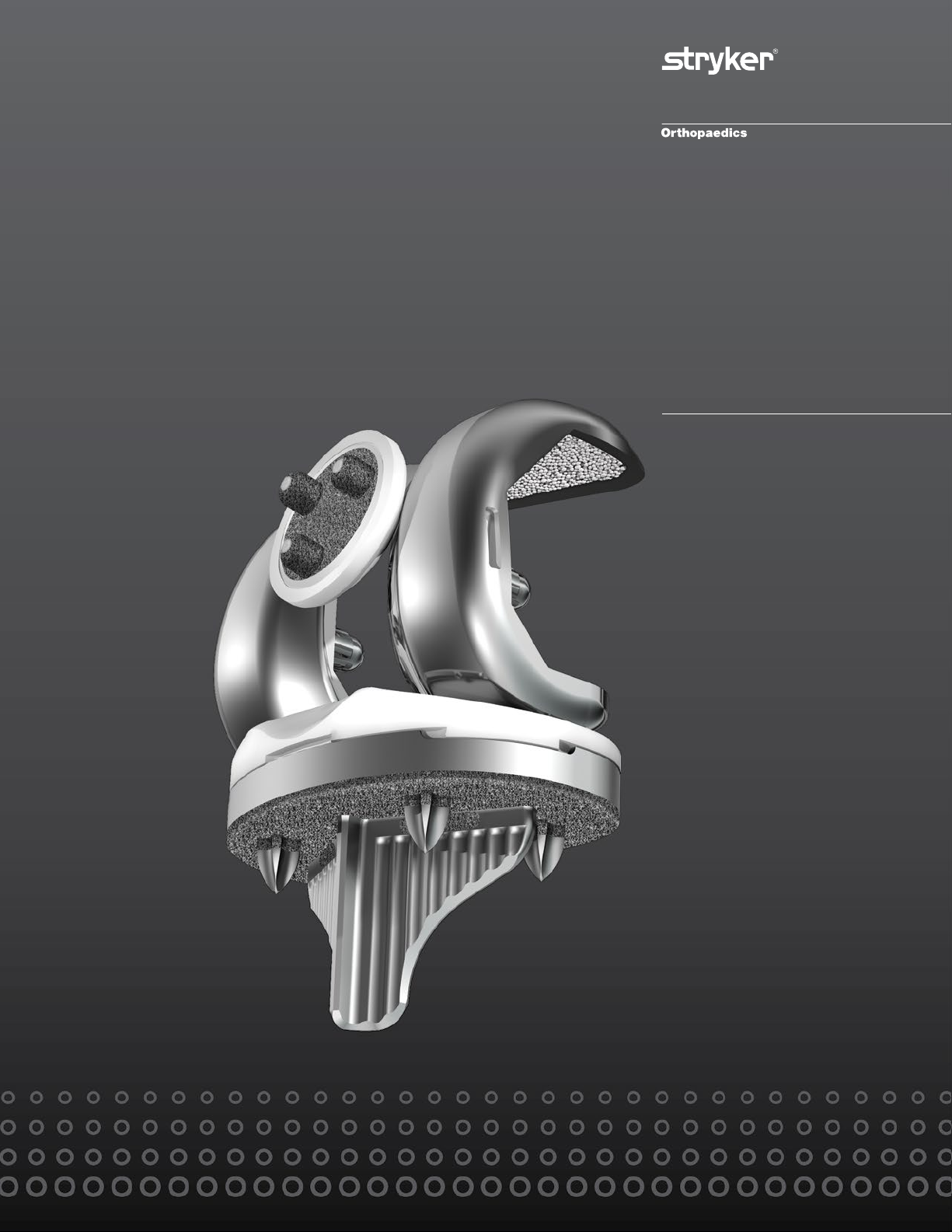
Triathlon Tritanium Baseplate
> The Triathlon Tritanium baseplate is designed to be
similar to the Triathlon Primary baseplate. It offers
the same profile and insert locking mechanism.
> The Triathlon Tritanium baseplate features four
cruciform pegs.
> The Triathlon Tritanium baseplate features Stryker’s
Tritanium 3D porous metal technology on the
Figure 1
underside of the baseplate, the proximal end of
the keel and the proximal end of each of the four
cruciform pegs.
> It is available in eight sizes and is indicated for both
cementless and cemented applications. Surgeons may
select an option based on preference and local bone
conditions.
Figure 2
> The Triathlon Tritanium baseplate is compatible with
all available posterior stabilizing (PS) and cruciate
retaining (CR) Triathlon femoral components for
both cemented and cementless applications, and
accepts available Triathlon cruciate retaining (CR),
condylar stabilizing (CS) and posterior stabilizing
(PS) inserts.
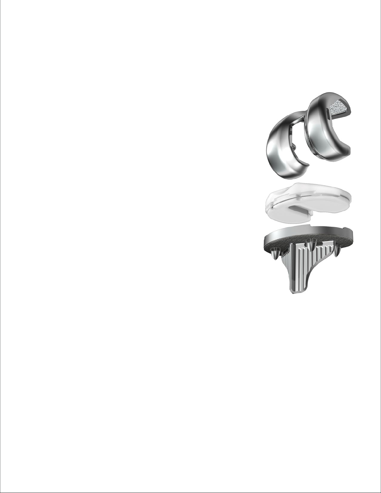
Triathlon Peri-Apatite
Cementless Beaded Femur
> The Triathlon cementless beaded femoral
components are available in both posterior stabilizing
(PS) and cruciate retaining (CR) configurations.
> The Triathlon cementless femoral components are
made from cobalt-chrome. They are coated with
cobalt-chrome beads and are available with and
without Peri-Apatite (PA) technology.
> Peri-Apatite (PA) is Stryker’s technology for
application of Hydroxyapatite (HA) to threedimensional beaded constructs.
4
CR
CS
PS
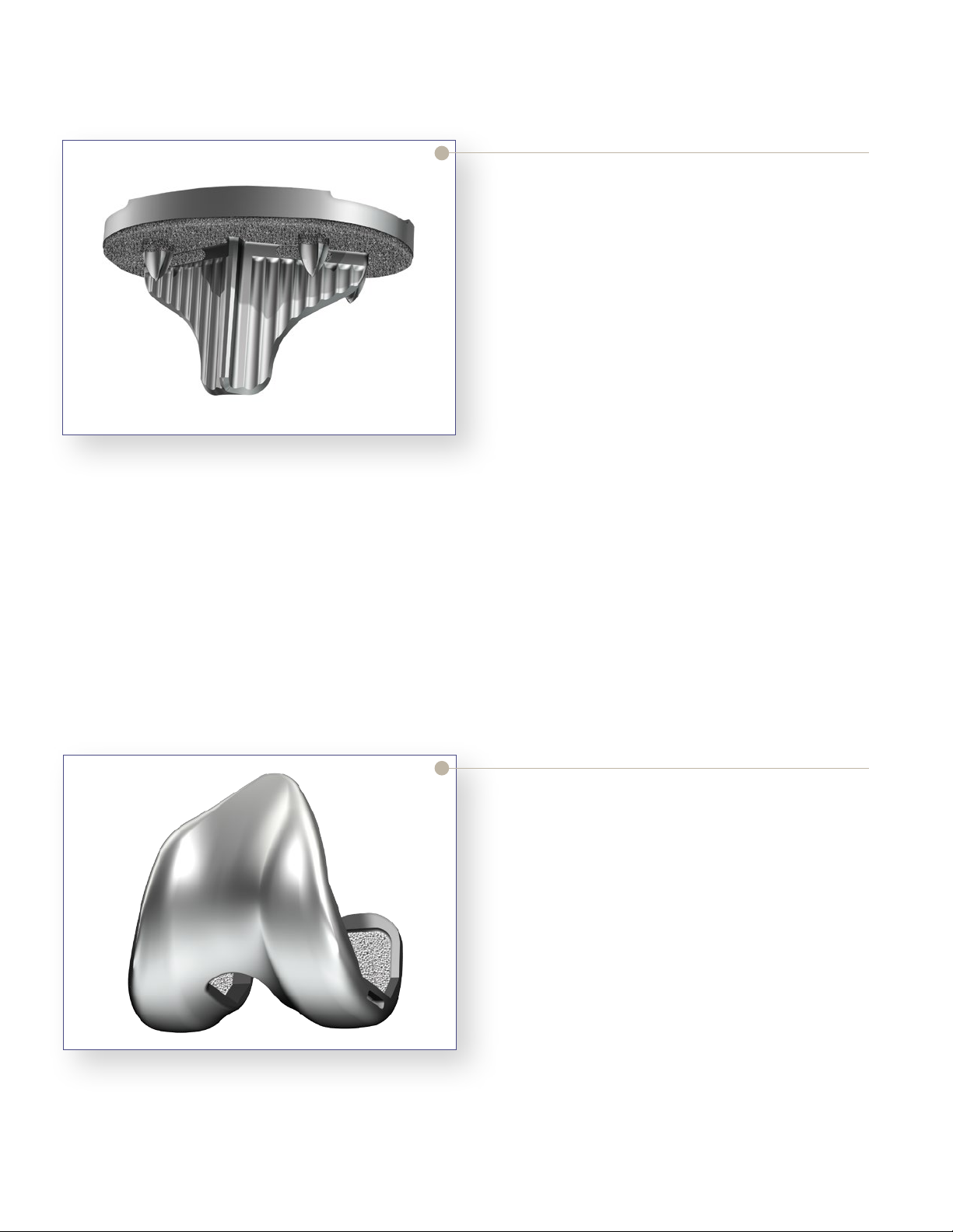
Triathlon Primary Tibial Inserts
> Compatible Triathlon inserts are available in three
configurations – cruciate retaining (CR), anteriorlipped/condylar stabilizing (CS) and posterior
stabilizing (PS).
> Triathlon primary inserts are available in eight sizes
with thicknesses of 9, 11, 13, 16 and 19mm, with
additional available thicknesses of 22 and 25mm for
the PS inserts.
> Triathlon primary inserts are available with
conventional polyethylene as well as Stryker’s X3
highly crosslinked polyethylene.
Figure 3
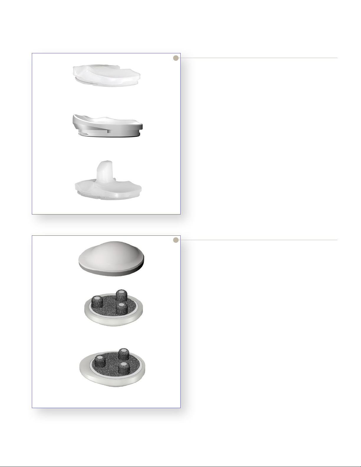
Symmetric Metal-Backed
Asymmetric Metal-Backed
Figure 4
Triathlon Tritanium
Metal-Backed Patella
> The Triathlon Tritanium Metal-Backed Patella
is indicated for both cemented and cementless
applications.
> The Triathlon Tritanium Metal-Backed patellar
components are available in symmetric and
asymmetric configurations. There are a total of 9
sizes which are compatible with all Triathlon femoral
and tibial components.
> The Triathlon Tritanium Metal-Backed Patella
features Stryker’s Tritanium 3D porous metal
technology, made from commercially pure titanium,
on the metal underside of the patella.
> The Triathlon Tritanium Metal-Backed patellar
components are available with conventional
polyethylene.
5
Femoral Preparation
Step 1 Distal Resection
Femoral
Preparation
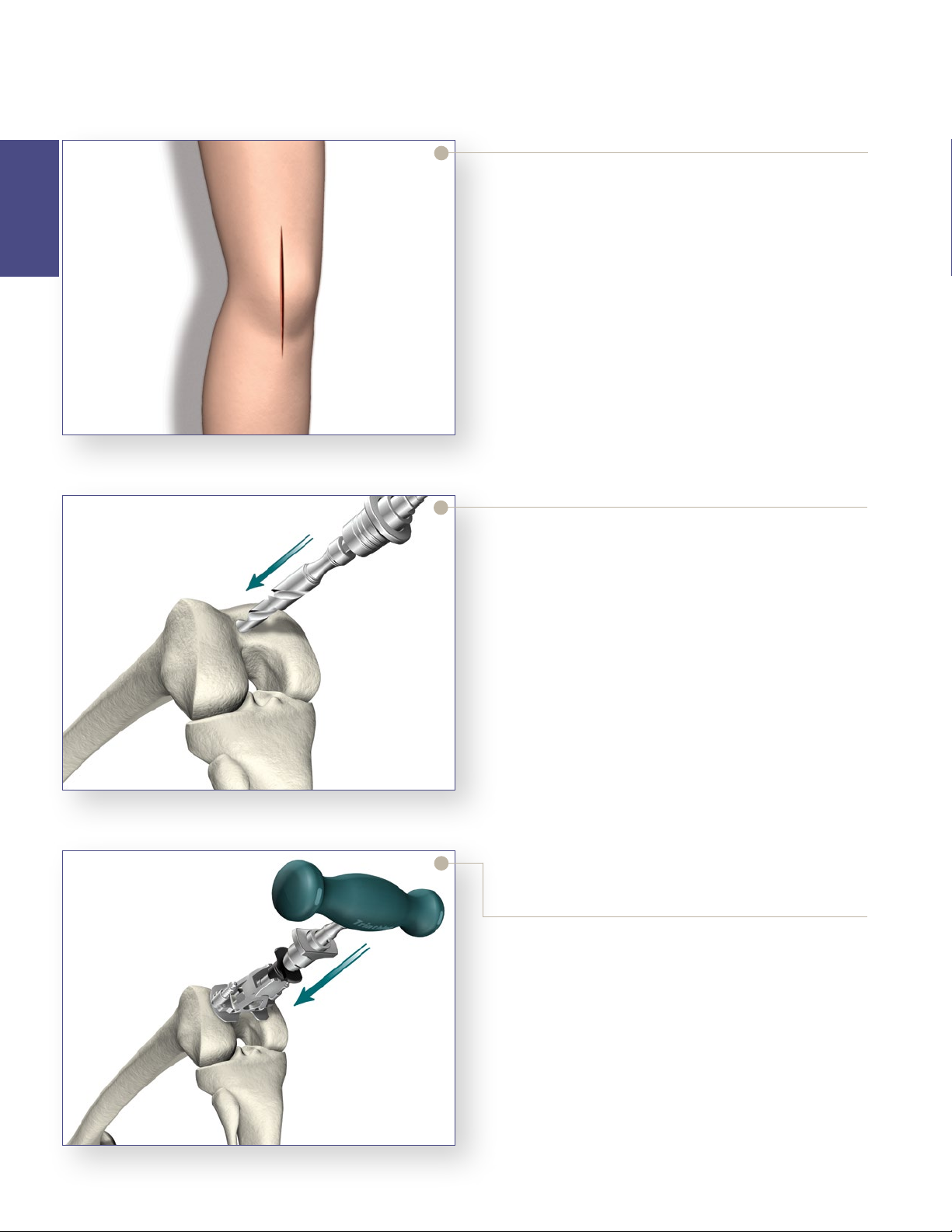
Exposure
> Triathlon Total Knee Arthroplasty can be performed
through any standard approach. A standard anterior
mid-line incision or other suitable approaches such
as mid-vastus, sub-vastus or quadriceps sparing may
be used based on surgeon preference.
> Any previous incision can be used or incorporated to
decrease the risk of skin slough.
> The capsule is entered through a medial parapatellar
approach.
Figure 5
Figure 6
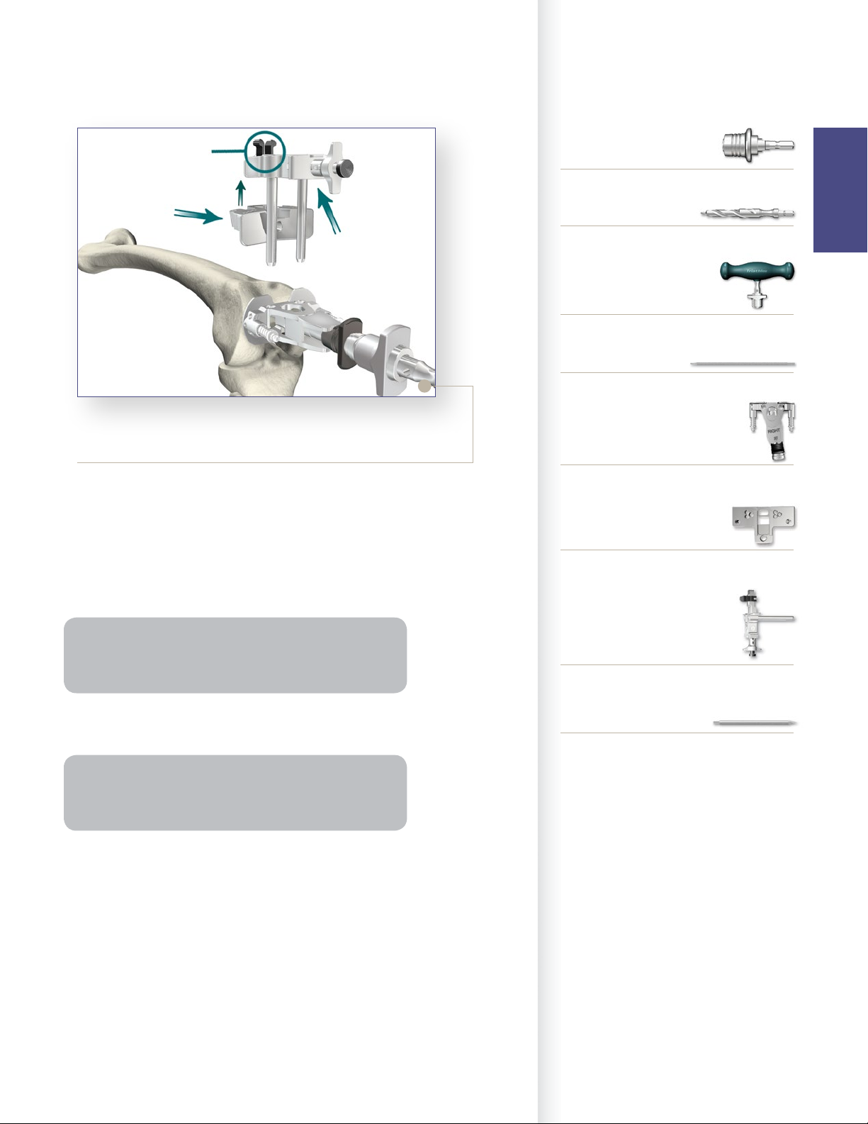
Femoral Intramedullary (IM) Alignment
> The Universal Driver allows for attachment of all
drills and pins. It may be attached directly to a
reamer, drill, or a Jacob’s chuck.
> Locate the IM drill hole. It is approximately 1cm
anterior to the femoral attachment of the posterior
cruciate ligament and slightly medial to the mid-line
of the distal femur.
> Attach the 3/8˝ IM Drill to the Universal Driver and
drill into the IM canal. The first diameter will create
a tight fit around the IM Rod. If further clearance
is desired, continue to drill until the larger step
diameter opens the hole.
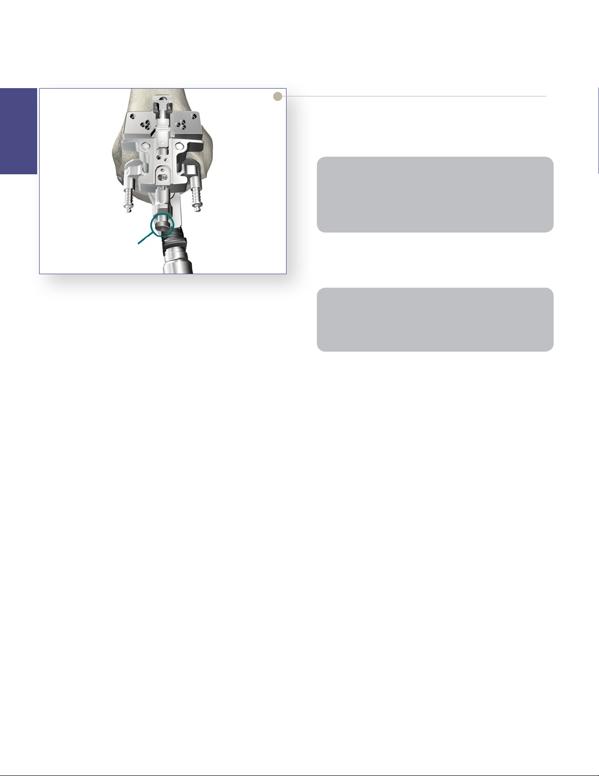
> Attach the T-Handle Driver to the 5/16˝ IM Rod.
> Insert the IM Rod into the Femoral Alignment Guide
as far proximal as possible. The Femoral Alignment
Guide is designed for use on either the left or right
knee and may be set to 5°, 6° or 7° of valgus.
> Set the instrument to the desired angle by pulling
back on the black knob of the Femoral Alignment
Guide and placing it in the appropriate notch.
> Advance the rod, with attached guide, slowly up the
IM canal until the desired depth is reached.
Figure 7
6
Instrument Bar
Button
Universal
Resection
Guide
Adjustment
Block
Figure 8
> Snap the Universal Resection Guide onto the
Adjustment Block and insert the posts of the
Adjustment Block into the two holes in the Femoral
Alignment Guide.
> Place the Femoral Alignment Guide in contact with
the more prominent distal femoral condyle and align
the guide in neutral position.
6541-4-801
Universal Driver
6541-4-538
3/8˝ IM Drill
6541-4-800
T-Handle Driver
6541-4-516
5/16˝ IM Rod
6541-1-657
Femoral Alignment Guide
6541-1-721
Universal Resection Guide
Femoral
Preparation
Tip: Align the Femoral Alignment Guide to the transepicondylar axis. The guide should usually have contact
with both medial and lateral trochlea for more stability.
> Impact the distal captured pins in the Femoral
Alignment Guide to aid in stabilization.
Note: Impacting a distal capture pin that does not
make contact with the femoral condyle may result in an
undesirable change in the alignment guide position.
> Pin the Distal Resection Guide to the anterior femur.
6541-1-600
Adjustment Block
6541-4-003
Headless Pins – 3˝
7
Femoral Preparation
Step 1 Distal Resection (continued)
Femoral
Preparation
> The Adjustment Block allows for an 8mm (the distal
thickness of the femoral component) and 10mm
(used to aid in the correction of a flexion contracture)
resection level.
Tip: The thickness of the resected femoral condyle
should be measured. In some cases, a greater resection
may be required. This can be accomplished by adjusting
the block as described below to achieve a greater
resection (+ 2mm or + 4mm).
Button
> Press the black button on the end of the Adjustment
Block and pull to set the resection to the desired level.
> Pin the Universal Resection Guide to the anterior femur.
Figure 9
Note: If the medial “O” pin hole is too close to the edge of
the bone (on smaller femurs), use the holes marked “2”
which are closer to the center of the bone. Please note:
this will limit the amount of further resection to 2mm.
8
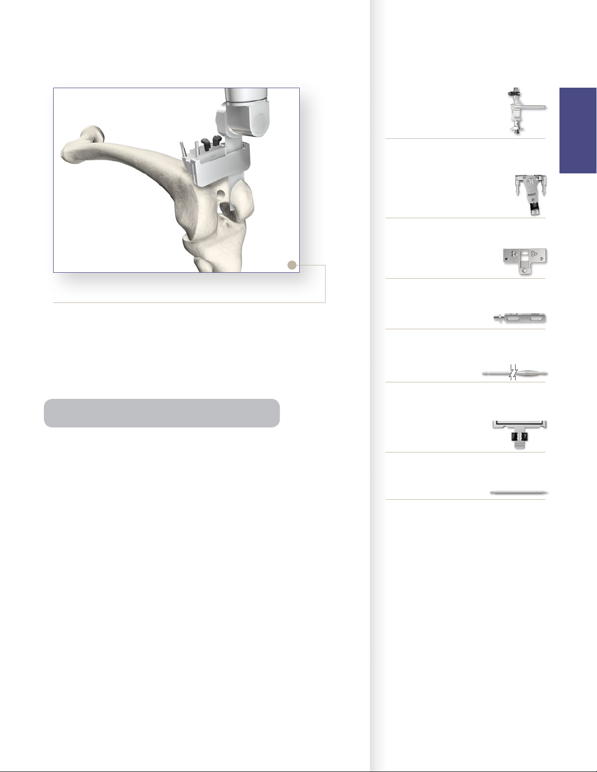
Figure 10
Instrument Bar
6541-1-600
Adjustment Block
6541-1-657
Femoral Alignment Guide
6541-1-721
Universal Resection Guide
Femoral
Preparation
Distal Resection
> After the Universal Resection Guide is pinned in
place, remove the IM Rod. The Femoral Alignment
Guide and the Adjustment Block may be removed by
squeezing the black tabs on the Adjustment Block.
> The distal femoral resection is made.
Tip: Use saline irrigation during distal femoral resection.
> An optional Modular Capture – may be attached to
the Universal Resection Guide. Squeeze the black
tabs on the Modular Capture – Distal Resection to
insert into the Universal Resection Guide. When
using a modular capture, a .050 (1.25mm) blade is
used.
> Remove the Modular Capture, measure the resection
and check the resection for flatness. Remove the
Universal Resection Guide.
6541-4-806
Universal Alignment Handle
6541-4-602
Universal Alignment Rods
6541-1-723
Modular Capture – Distal Resection
6541-4-003
Headless Pins – 3˝
9

Femoral Preparation
Step 2 Femoral Sizing
Femoral
Preparation
“EPI”
Line
Indicator
Hole for Pin
to Reference
Whiteside’s Line
Figure 11
> Assemble the Femoral Sizer with the Femoral Stylus
in the lateral hole (for both a left or right knee) and
set the stylus length to an approximate size.
> Set the rotation to LEFT for a left knee and RIGHT
for a right knee and adjust to the desired amount of
external rotation.
> The Femoral Sizer also sets the final rotation of the
femoral component. Additional checks for rotation
may be made by lining up the epicondyles with the
reference lines marked “EPI” or assessing Whiteside’s
line with a pin through the hole in the top of the guide.
Note: In the event of a hypoplastic femoral condyle: Pin
the Femoral Sizer through the EPI hole on the unaffected
side for stability. Rotate the Femoral Sizer and assess
rotation using the rotational checks mentioned above.
> Position the assembly flush on the resected distal
femur, sliding the feet of the Femoral Sizer under
the posterior condyles. The Femoral Stylus point
should be placed at the anticipated level of resection,
commonly the lateral cortex.
Figure 12
> It is important that the Femoral Stylus point rest on
bone and not on soft tissue.
> The size is determined by the position of the scribe
mark on the Femoral Stylus shaft within the sizing
window.
10
Figure 13
Instrument Bar
6541-1-603
Femoral Sizer
6541-1-605
Femoral Stylus
6541-4-003
Headless Pins – 3˝
Femoral
Preparation
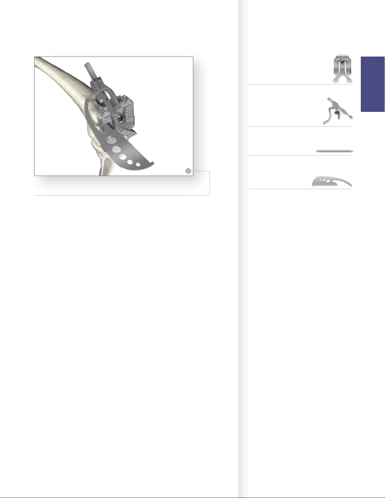
Figure 14
> It is recommended that the anterior resection level be
checked to further confirm the correct size by sliding
a Bladerunner through the sizing guide’s size-specific
anterior slots and assessing the resection. If it appears
that there is a potential for notching, the next larger
size component will need to be chosen. Ensure the
femoral component chosen is compatible with the
size of the tibial component selected during tibial
preparation.
> Once size confirmation is complete, attach the 1/8˝
Peg Drill to the Universal Driver and create fixation
pin-holes (for the 4:1 Cutting Block) through the
holes on the face of the Femoral Sizer marked “EPI”.
6541-4-400
Bladerunner
11
Femoral Preparation
Step 3 Anterior, Posterior and Chamfer Cuts
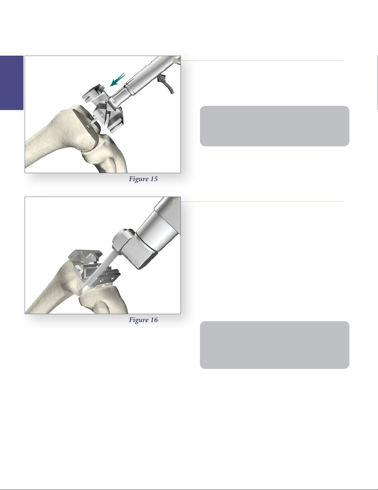
4:1 Cutting Block Fixation
> Locate the fixation pegs of the appropriate size
Femoral
Preparation
Note: Check run-out of the anterior cut. If not enough
anterior bone is resected, consider selecting the next
smaller size 4:1 Cutting Block. Ideally, the cut should be
flush with the distal femur.
> Pin the 4:1 Cutting Block in place for stability.
Figure 15
Express 4:1 Cutting Block into the pin holes created
on the distal femur.
Figure 16
Femoral Anterior, Posterior and
Chamfer Cuts
> Complete the remaining four femoral bone
resections.
> The use of a .050˝ (1.25mm) thick sawblade is
recommended.
> The order of bone resections is not critical; however,
a recommended sequence for improved stability of
the 4:1 Cutting Block is:
1. Anterior cortex.
2. Posterior condyles.
3. Posterior chamfer.
4. Anterior chamfer.
Note:
• Cutting the anterior chamfer last helps stabilize the
cutting guide.
• It is advisable to pay close attention to minimizing
the bias on the sawblade during these resections.
> Remove the 4:1 Cutting Block.
12
Femoral Preparation
Step 4 PS Box Preparation
Instrument Bar
PS Box Preparation
> If it is determined that a PS femoral component will
be used, the distal femur must be prepared for the
PS box. Place the appropriate sized PS Box Cutting
Guide on the resected distal femur.
Note: The appropriate size is the same as the size 4-in-1
cutting block that was used to prepare the distal femur.
For example, if a size 3 “4-in-1 Cutting Block” was used
to prepare the distal femur, select the size 3 PS Box
Cutting Guide.
> M/L placement of the guide is based primarily on
best coverage of the distal bone and alignment of the
box opening with the intercondylar notch.
Optional surgical tip: Use a CR Femoral Trial of the
same size to identify the preferred M/L position of
the PS Box Cutting Guide.
• Place the appropriate sized CR Femoral Trial on to
the prepared femur.
• Adjust the M/L placement of the Femoral Trial
to achieve the desired position of the femoral
component.
See Catalog
Express 4:1 Cutting Block
Femoral
Preparation
6541-7-806
MIS 4:1 Impactor/Extractor
See Catalog
MIS PS Box Cutting Guide
See Catalog
CR Femoral Trial
• Using a surgical marketing pen, mark the location
of the distal peg prep holes through the CR
Femoral Trial.
• Remove the CR Femoral Trial and line-up the PS
Box Cutting Guide on the distal femur with the
previously marked holes.
13
Femoral Preparation
Step 4 PS Box Preparation (continued)
Femoral
Preparation
Figure 17
PS Box Cutting Guide
> Pin the PS Box Cutting Guide in place using
Headless Pins.
> Optional surgical tip: To provide the appropriate
anterior/posterior and medial/lateral stability with a
minimal number of pins, place one pin distally and
one pin anteriorly.
Figure 18
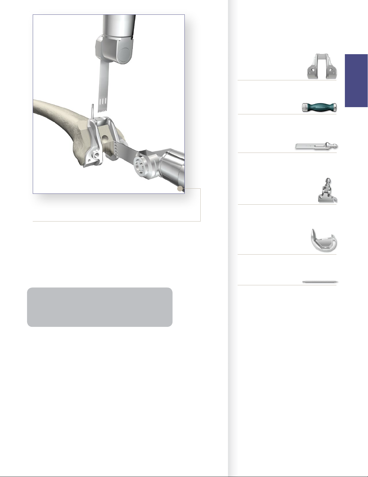
There are two ways to continue the PS box preparation:
PS Box Preparation Option: Chisel and Saw
> Option A: Chisel and Saw: Cut the cortical rim
on both sides of the posterior-most portion of the
intercondylar notch using the oscillating saw.
• Assemble the Box Chisel and insert into the slot.
• Impact the Box Chisel with a mallet until seated
to the stop. Leave the Box Chisel in place to act as
a reference plane. Cut the medial and lateral edges
of the box with an oscillating saw to complete the
bone resection as shown.
• Avoid biasing the blade during resection for
optimal bone conservation.
14
Instrument Bar
See Catalog
MIS PS Box Cutting Guide
6541-4-810
Impaction Handle
6541-4-709
Box Chisel
Femoral
Preparation
Figure 19
PS Box Preparation Option: Saw Only
> OptionB: Saw Only: Use a narrow oscillating saw
through the proximal slot to resect the distal portion
of the femur. An oscillating or reciprocating saw can
be used to resect the medial and lateral borders of
the intercondylar notch to the proximal portion of
the cutting guide.
Note: After completion of options A or B, the surgeon
may choose to use the optional and recommended
Triathlon PS Femoral Finishing Punch to complete
preparation of the box.
> Prior to trialing with a PS Femoral Trial, assure the
box is prepared properly and remove all remaining
bone from the prepared box.
See Catalog
Triathlon PS Femoral Box Finishing Punch
See Catalog
PS Femoral Trial
6541-4-003
Headless Pins – 3˝
15
Femoral Preparation
Step 4 PS Box Preparation (continued)
Optional PS Box Preparation
Finishing Punch
Femoral
Preparation
Figure 20
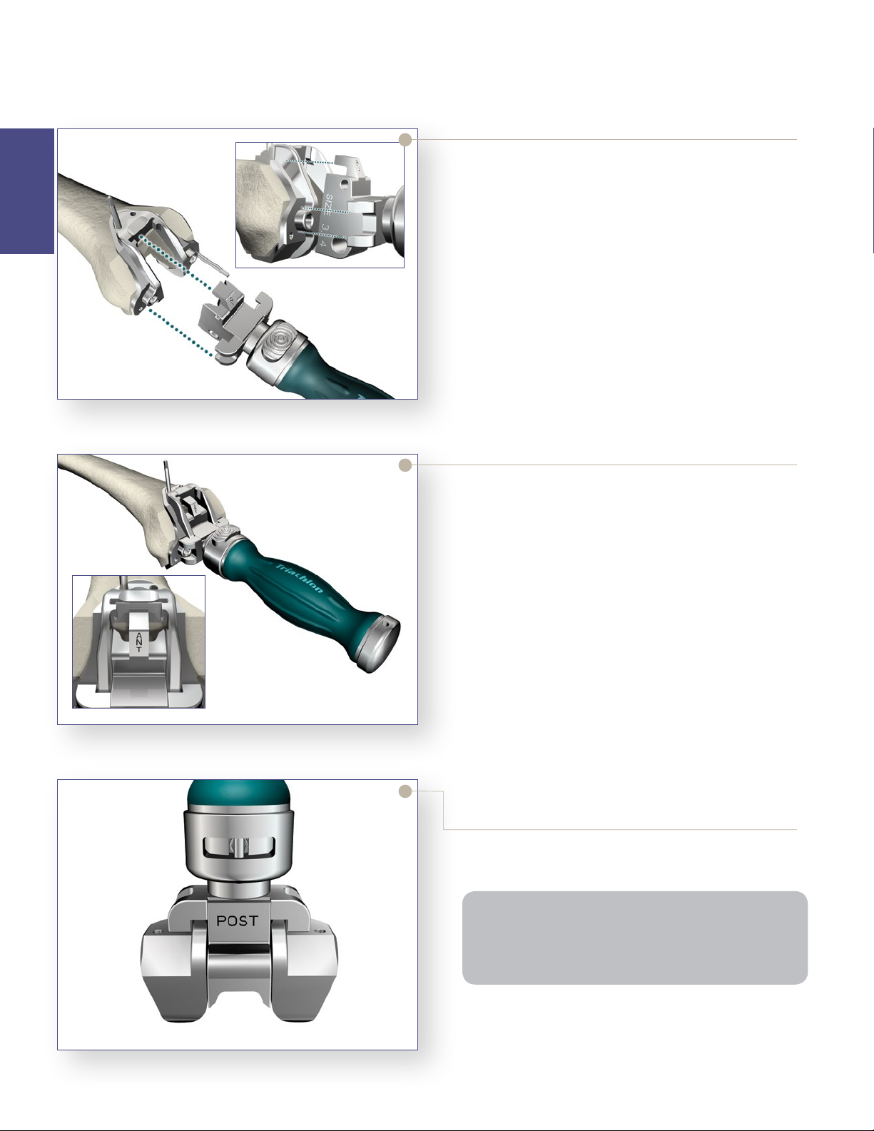
If the optional Triathlon PS Femoral Box Finishing
Punch is chosen:
> The chisel should be fully removed from the PS
Box Cutting Guide prior to using the Triathlon PS
Femoral Box Finishing Punch.
> Secure the appropriate size Triathlon PS Femoral
Box Finishing Punch to the Triathlon Impaction
Handle. There are four Triathlon PS Femoral Box
Finishing Punches (Size 1-2, Size 3-4, Size 5-6 and
Size 7-8).
> Properly orient the Triathlon PS Femoral Box
Finishing Punch, assuring the anterior side is facing
upwards.
Seating of the PS Box Finishing Punch
If the optional Triathlon PS Femoral Box Finishing
Punch is chosen:
> Impact the Triathlon PS Femoral Box Finishing
Punch through the PS Box Cutting Guide until
properly seated.
> The Triathlon PS Femoral Box Finishing Punch
is properly seated when the stop of the Finishing
Punch is centered over the PS Box Cutting Guide
drill holes. See figure on left which depict the
Triathlon PS Femoral Box Finishing Punch properly
seated on the PS Box Cutting Guide.
16
Figure 21
Figure 22
> When seated properly, there should be a gap between
the anterior nose of the Triathlon PS Femoral Box
Finishing Punch and the PS Box Cutting Guide.
> Remove the Triathlon PS Femoral Box Finishing
Punch with the Triathlon Slap Hammer.
> Remove pins and the PS Box Cutting Guide from the
prepared distal femur.
Note: The Triathlon PS Femoral Box Finishing Punch
is designed to be used with the PS Box Cutting Guide
and should not be impacted onto the prepared distal
femur without the PS Box Cutting Guide in place.
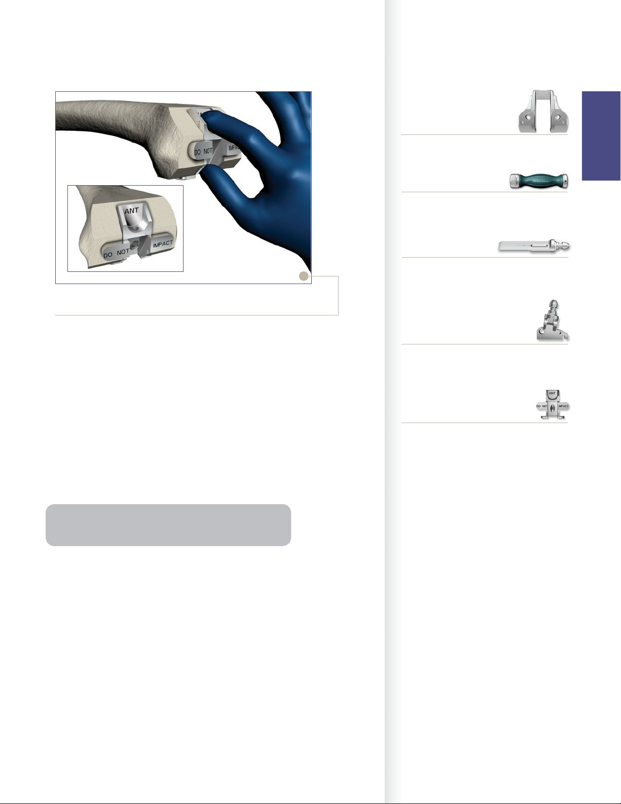
Figure 23
Instrument Bar
See Catalog
MIS PS Box Cutting Guide
Femoral
Preparation
6541-4-810
Impaction Handle
6541-4-709
Box Chisel
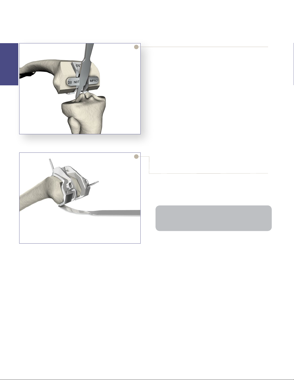
PS Box Femoral Box Trial/Protector
> If the optional and recommended Triathlon PS
Femoral Box Trial/Protector is chosen:
• Remove the PS Box Cutting Guide.
• Place by hand (not through impaction) the
appropriate size Triathlon PS Femoral Box Trial/
Protector into the prepared box to assure accuracy
of the box preparation. There are two Triathlon PS
Femoral Box Trial/Protectors (Size 1-4 and Size 5-8).
• The box trial/protector is fully seated when both
the distal and posterior “wings” are flush with the
bone.
Note: Triathlon PS Femoral Box Trial/Protector assesses
the accuracy of M/L box width and box depth.
See Catalog
Triathlon PS Femoral Box Finishing Punch
See Catalog
Triathlon PS Femoral Box Trial/Protector
17
Femoral Preparation
Step 4 PS Box Preparation (continued)
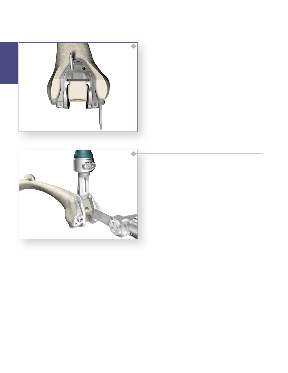
Femoral Box Protection During Tibia
Subluxation
Femoral
Preparation
Figure 24
> To protect the prepared femoral box prior to trialing
with a femoral component, place the Triathlon PS
Femoral Box Trial/Protector into the prepared box
by hand (not through impaction).
> Ensure the box trial is fully seated on the distal and
posterior resections as described above in the box
trialing step.
• The Triathlon PS Femoral Box Trial/Protector
features a slot in which a retractor can be placed
to lever against the distal femur during tibial
subluxation.
• If preferred, select an extraction tool that fits into
the retractor hole for ease of removal.
• Remove the PS Femoral Box Trial/Protector prior
to assembling and implanting the Triathlon PS
femoral component.
To avoid femoral component impingement and to
improve flexion, all osteophytes beyond the posterior
condyles as well as those medially and laterally may be
removed with an osteotome.
Figure 25
Note: If it is difficult to reach the posterior osteophytes
in a tight knee, the tibial resection can be made and
then the osteophytes can more easily be removed.
18
 Loading...