

Stryker Triathlon Surgical Manualline

®
TRIATHLON
Single-Use Instruments
Orthopaedics
Surgical
Protocol

Triathlon® Knee System
Single-Use Instruments Surgical Protocol
Table of Contents
Indications .............................................................2
Exposure ...............................................................6
Tibial Preparation ......................................................6
Rotational Alignment ..................................................6
Varus/Valgus Alignment ...............................................7
Flexion/Extension Alignment ...........................................7
Establishing the Tibial Resection Level ...................................8
Final Tibial Resection ..................................................9
Femoral Preparation ................................................... 10
Femoral Intramedullary Alignment .....................................10
Distal Femoral Resection ..............................................14
Femoral A/P Sizing ...................................................15
Femoral Anterior, Posterior, and Chamfer Resections .....................18
PS Box Preparation ...................................................20
Femoral Trial Assessment ..............................................21
Tibial Component Sizing ............................................... 24
Tibial Keel Punching ..................................................25
Patella Preparation .................................................... 26
Trial Assessment .....................................................27
Component Implantation .............................................. 28
PS or CR Femoral Component – Cemented/Cementless ...................28
Tibial Component Implantation – Cemented/Cementless ..................29
Tibial Insert Implantation .............................................30
Patellar Component – Cemented/Cementless ............................30
Closure ............................................................... 31
Catalog ............................................................... 32
1
Triathlon® Knee System
Single-Use Instruments Surgical Protocol
Indications
General Total Knee Arthroplasty (TKA) Indications include:
• Painful, disabling joint disease of the knee resulting from: noninammatory
degenerative joint disease (including osteoarthritis, traumatic arthritis, or avascular
necrosis), rheumatoid arthritis or post-traumatic arthritis.
• Post-traumatic loss of knee joint conguration and function.
• Moderate varus, valgus, or exion deformity in which the ligamentous structures
can be returned to adequate function and stability.
• Revision of previous unsuccessful knee replacement or other procedure.
• Fracture of the distal femur and/or proximal tibia that cannot be stabilized by
standard fracture management techniques.
Additional Indications for Posterior Stabilized (PS) Components:
• Ligamentous instability requiring implant bearing surface geometries with
increased constraint.
• Absent or non-functioning posterior cruciate ligament.
• Severe anteroposterior instability of the knee joint.
e Triathlon Total Knee System beaded and beaded with Peri-Apatite components
are intended for uncemented use only.
e Triathlon Tritanium Tibial Baseplate and Tritanium Metal-Backed Patella
components are indicated for both uncemented and cemented use.
e Triathlon All-Polyethylene tibial components are indicated for cemented use only.
2
Contraindications
• Any active or suspected latent infection in or about the knee joint.
• Distant foci of infection which may cause hematogenous spread to the implant site.
• Any mental or neuromuscular disorder which would create an unacceptable risk of
prosthesis instability, prosthesis xation failure, or complications in postoperative care.
• Bone stock compromised by disease, infection or prior implantation which cannot
provide adequate support and/or xation to the prosthesis.
• Skeletal immaturity.
• Severe instability of the knee joint secondary to the absence of collateral ligament
integrity and function.
e Triathlon Single-Use Instruments are intended for use in a single
Total Knee Arthroplasty.
See package insert for warnings, precautions, adverse eects and other essential
product information.
Patient Counseling
Surgeons should discuss all relevant contraindications, adverse eects and the need for
post-implantation protection with their patients.
3
Triathlon® Knee System
Single-Use Instruments Surgical Protocol
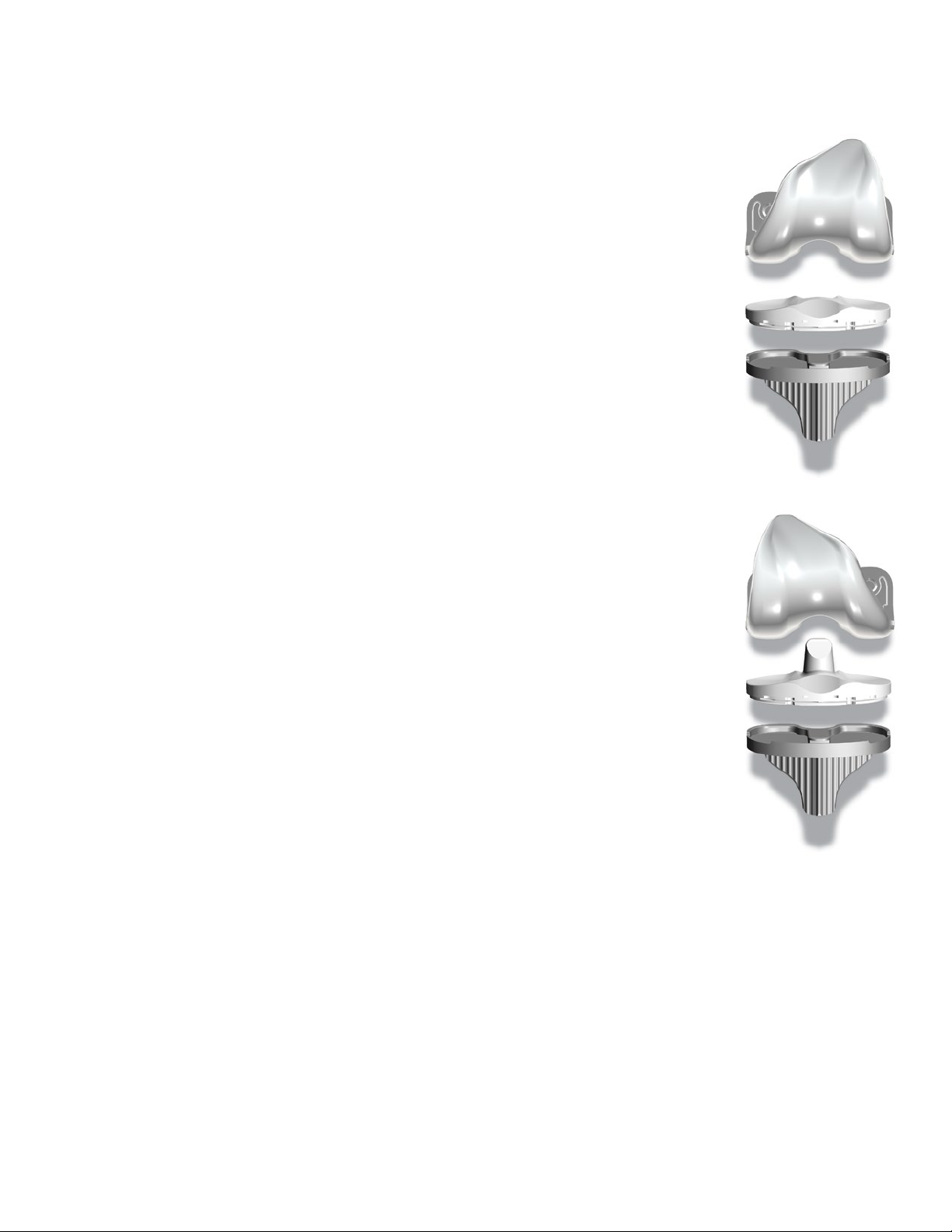
CR Femoral
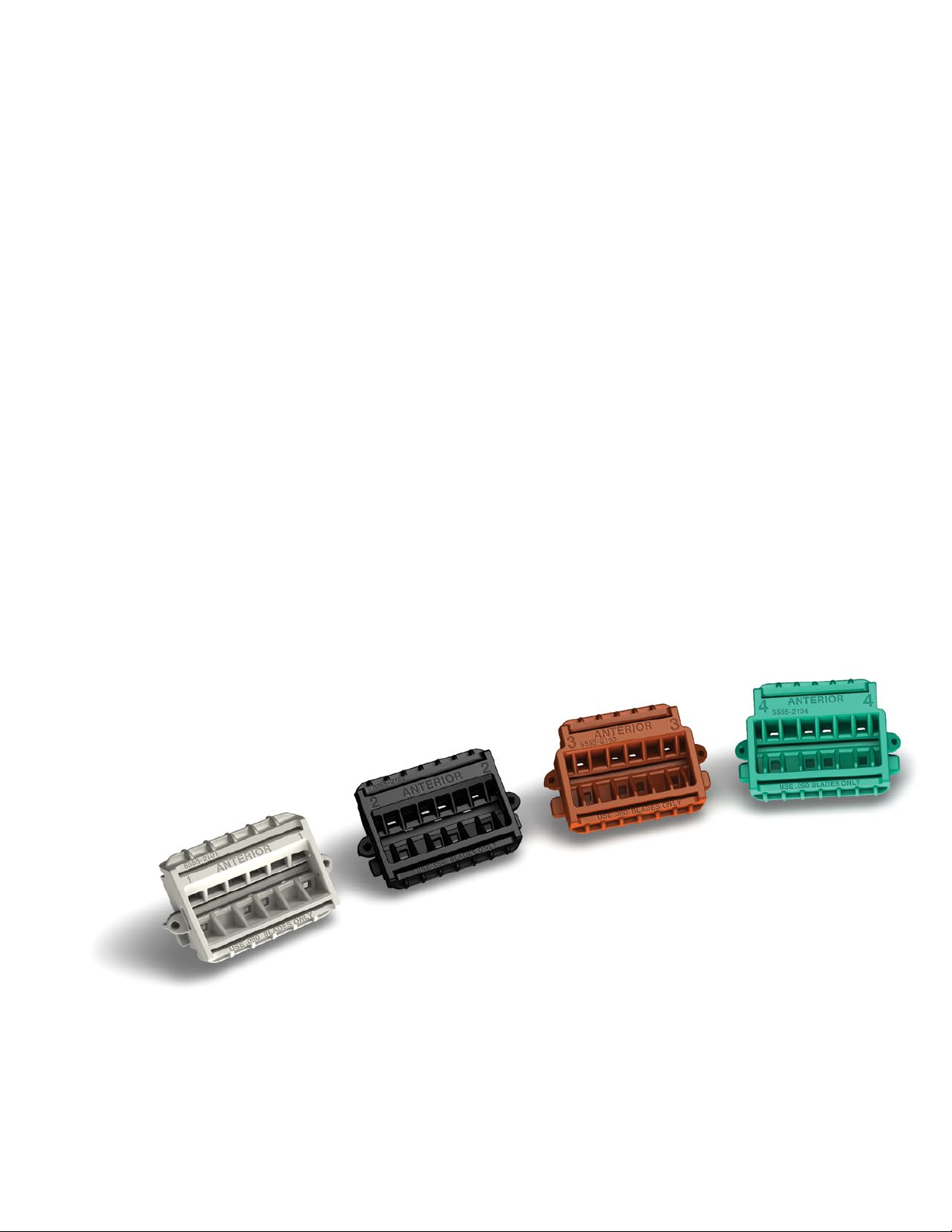
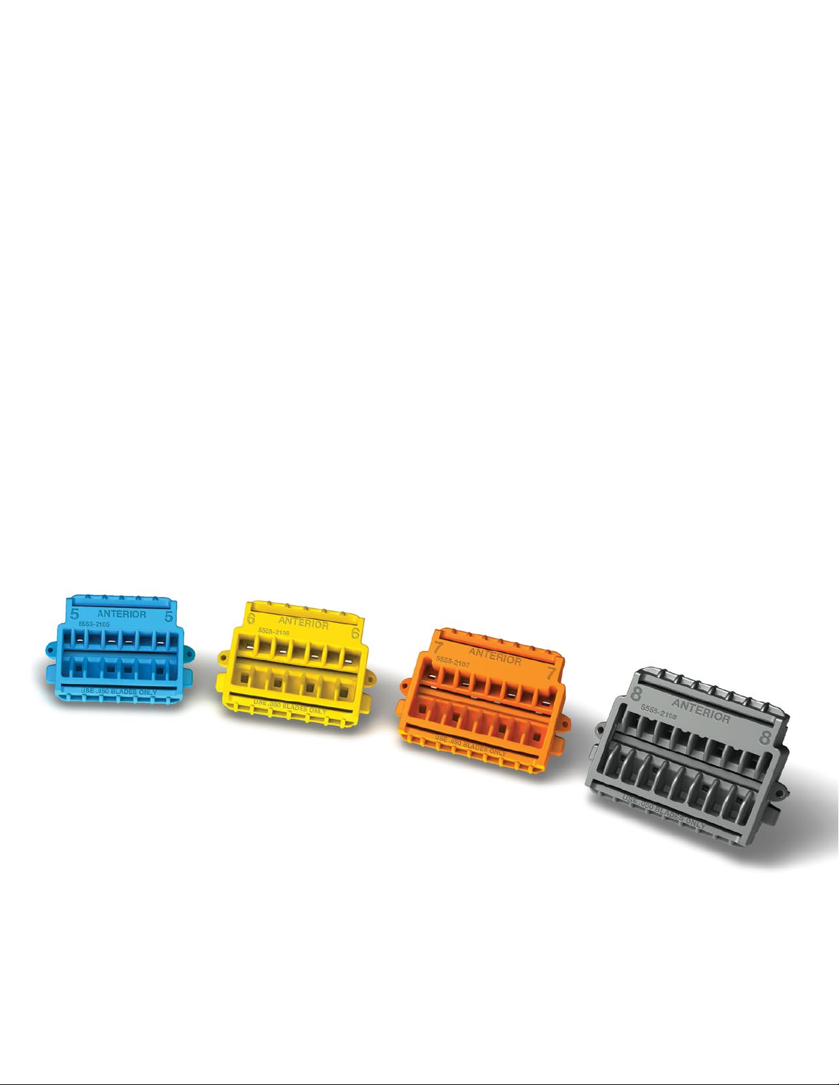
Triathlon CR Single-Use Femoral Prep Kit
Part Numbers Size
5555-2201 1
5555-2202 2
5555-2203 3
5555-2204 4
5555-2205 5
5555-2206 6
5555-2207 7
5555-2208 8
CR Tibial
Triathlon CR Single-Use Tibial Prep Kit
Part Numbers Size
5555-2321 1
5555-2322 2
5555-2323 3
5555-2324 4
5555-2325 5
5555-2326 6
5555-2327 7
5555-2328 8
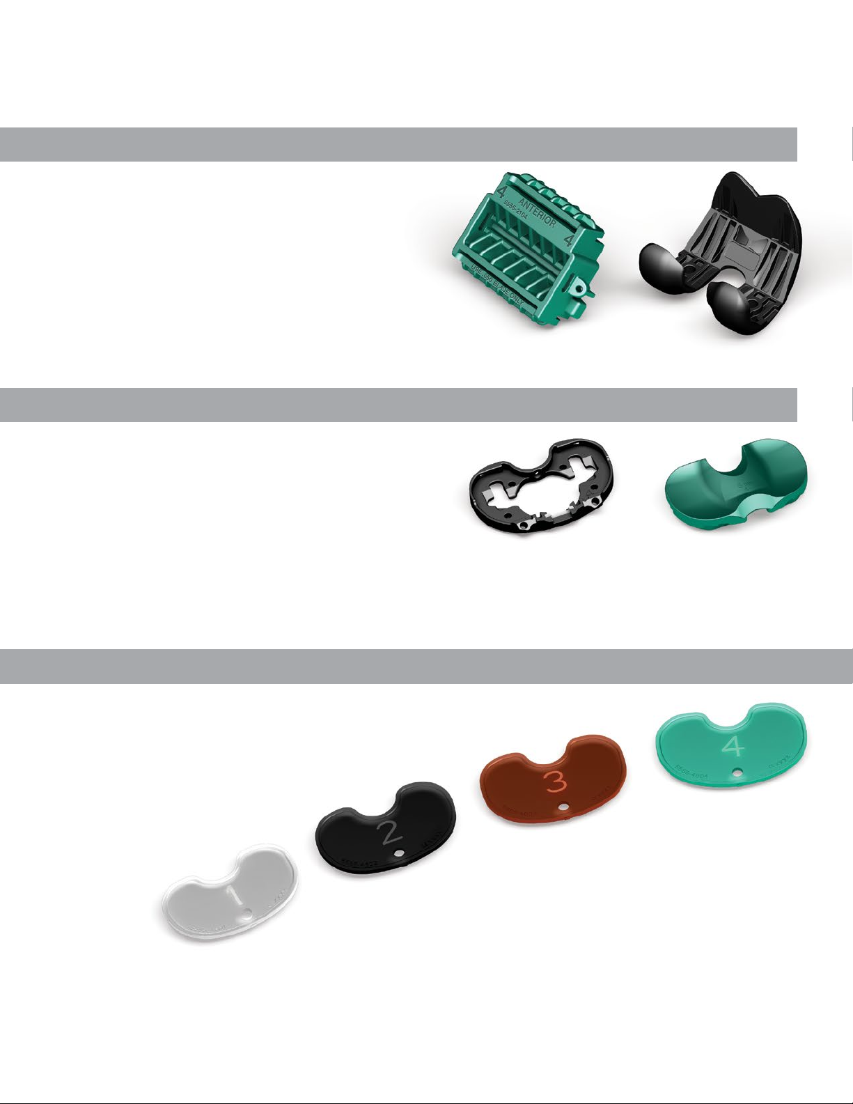
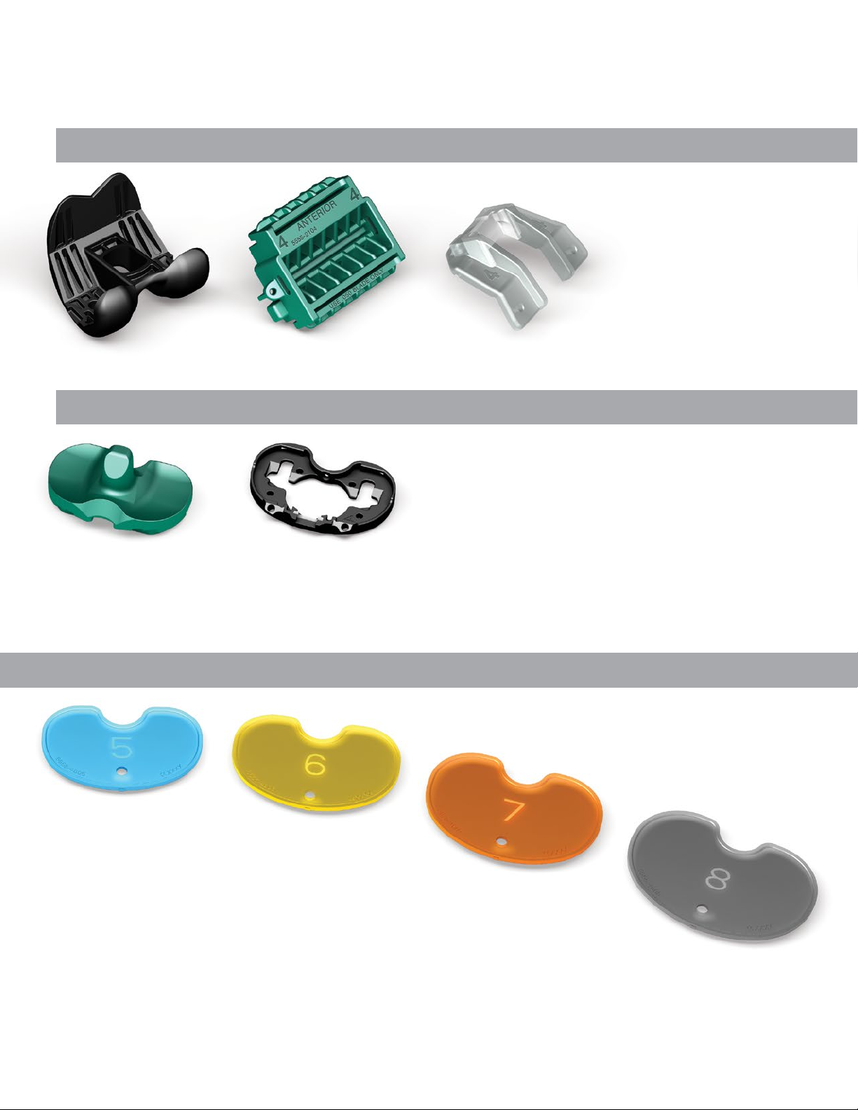
Tibial Sizers Tibial Sizers
Triathlon Single-Use Tibial Sizer Prep Kit
Part Number Sizes
5555-4600 1 – 8
4
PS Femoral
Triathlon PS Single-Use Femoral Prep Kit
Part Numbers Size
5555-2251 1
5555-2252 2
5555-2253 3
5555-2254 4
5555-2255 5
5555-2256 6
5555-2257 7
5555-2258 8
PS Tibial
Triathlon PS Single-Use Tibial Prep Kit
Part Numbers Size
5555-2361 1
5555-2362 2
5555-2363 3
5555-2364 4
5555-2365 5
5555-2366 6
5555-2367 7
5555-2368 8
Triathlon Single-Use Tibial Sizer Prep Kit
Part Number Sizes
5555-4600 1 – 8
5

Triathlon® Knee System
Single-Use Instruments Surgical Protocol
Exposure
> A standard anterior midline incision can be utilized.
Any previous incision can be used or incorporated
to decrease risk of skin slough.
> e capsule can be entered through a modied mid-
vastus approach, which makes a skin incision medial
to the patella from just above the tibial tubercle to
just above the patella.
> Use a so tissue approach that allows adequate
Tibial
Preparation
patella visualization and sucient knee exion.
Headless
Pin
Figure 1
Locking
Switch
1
2
Figure 2
is surgical technique describes cutting the tibia rst,
followed by the femur and then patella. e sequence
may be varied based upon surgeon preference.
In some patients it may be dicult to cut the femur rst
and get proper rotation due to the tibia being in the way
of the placement of the femoral sizer. In these cases it
may be benecial to cut the distal femur, then tibia, and
then go back to size and nish the femoral cuts.
Tibial Preparation
> e tibia is prepared using the Triathlon
extramedullary alignment system. Retractors may be
placed medially, laterally, and posteriorly to expose
the tibial plateau for preparation. It is important to
remove all osteophytes, menisci and remaining so
tissues. Menisci can be removed before or aer the
bone cut. If the PCL has been retained, an optional
retractor is available to cradle the PCL for increased
exposure. e knee is exed anywhere from 45
degrees to more than 90 degrees of exion depending
on surgeon preference. e tibia may be subluxed or
dislocated as required.
> e tibial plateau referencing arm of the proximal
rod is placed on the proximal tibia just anterior to
the ACL insertion. A rongeur may remove any
osteophytes that prevent satisfactory positioning.
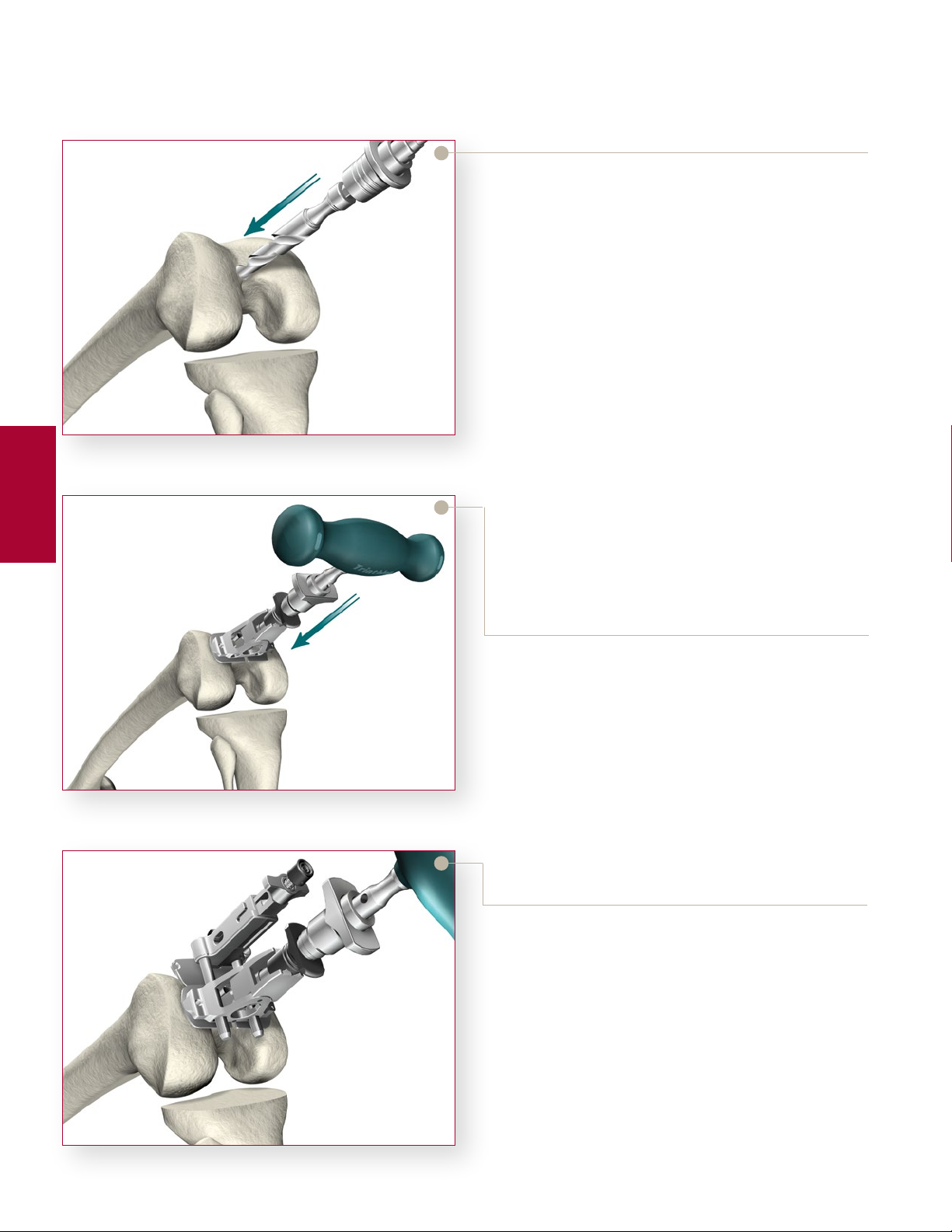
Rotational Alignment
> e assembly must be in the proper rotational
alignment. e most common landmark referenced
is the tibial tubercle. e assembly should be
aligned with the medial third of the tibial tubercle.
> Once the rotational alignment is determined, a
headless pin is placed through the posterior xation
hole in the proximal assembly to lock it in place.
Either the anterior or posterior xation holes may
Figure 3
6
be used to set the exion extension and rotational
alignment.
Instrument Bar
6541-6-700
MIS Uncaptured Tibial Resection Guide-Right
2
1
Figure 4
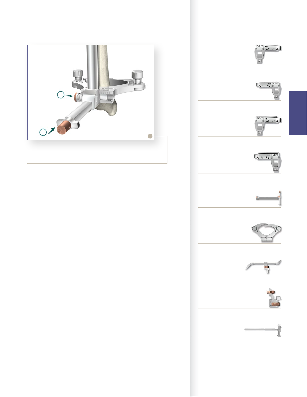
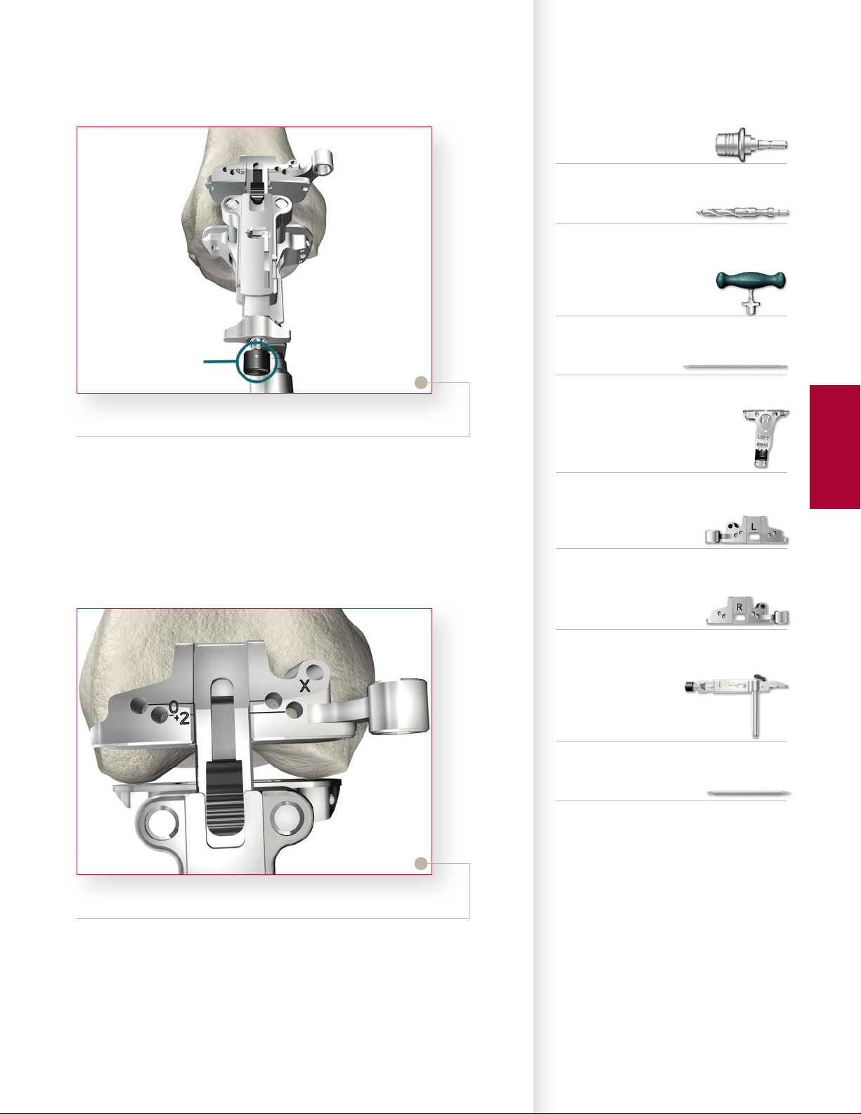
Varus-Valgus Alignment
> Once the proximal portion of the assembly is xed, varus-valgus
alignment can be attained by adjusting the distal assembly to the proper
medial/lateral position. e position should be in the center of the talus,
not the center of the ankle. e center of the talus usually resides 5 to
10mm medial to the mid-point between the medial and lateral malleoli.
> Medial/lateral oset can be adjusted by pushing the bronze button on the
anterior portion of the distal assembly 1. Once alignment is achieved,
the bronze button is released and the assembly is xed in place.
> e proper tibial resection should be 0 degrees in the coronal plane of the
tibia.
6541-6-701
MIS Uncaptured Tibial Resection Guide-Le
Tibial
Preparation
6541-6-702
MIS Captured Tibial Resection Guide-Right
6541-6-703
MIS Captured Tibial Resection Guide-Le
6541-2-610
Tibial Alignment Distal Assembly EM
6541-2-609
Tibial Alignment Ankle Clamp EM
Flexion-Extension Alignment
> Once rotational alignment is determined, the ankle clamp is placed just
proximal to the ankle at the level of the maleolus. e distal assembly
locking switch, located approximately halfway up the rod, is then
locked. Adjustments to the exion extension alignment can be made by
depressing the button located on the inferior le hand side of the distal
assembly 2.
> Flexion and extension alignment is proper when the long axis of the
assembly parallels the weight-bearing axis of the tibia in both the coronal
and sagittal planes. Usually, there is less space between the assembly
and the tibia proximally than there is distally. Alignment can be veried
using the universal alignment tower and universal alignment rod, which
can be assembled to the anterior inferior hole on the tibial adjustment
housing.
> e proper tibial resection should be 0 to 3 degrees of slope in the
sagittal plane, depending on surgeon preference and the type of implant
used.
Note: It is important that there is no anterior slope in the tibial resection.
6541-2-429
Tibial Stylus
0º slope 6541-2-704
3º slope 6541-2-705
Tibial Adjustment Housing
6541-6-611
MIS Proximal Rod EM
7
Triathlon® Knee System
Single-Use Instruments Surgical Protocol
Referencing the medial
compartment
Tibial
Preparation
Referencing the lateral
compartment
Figure 5
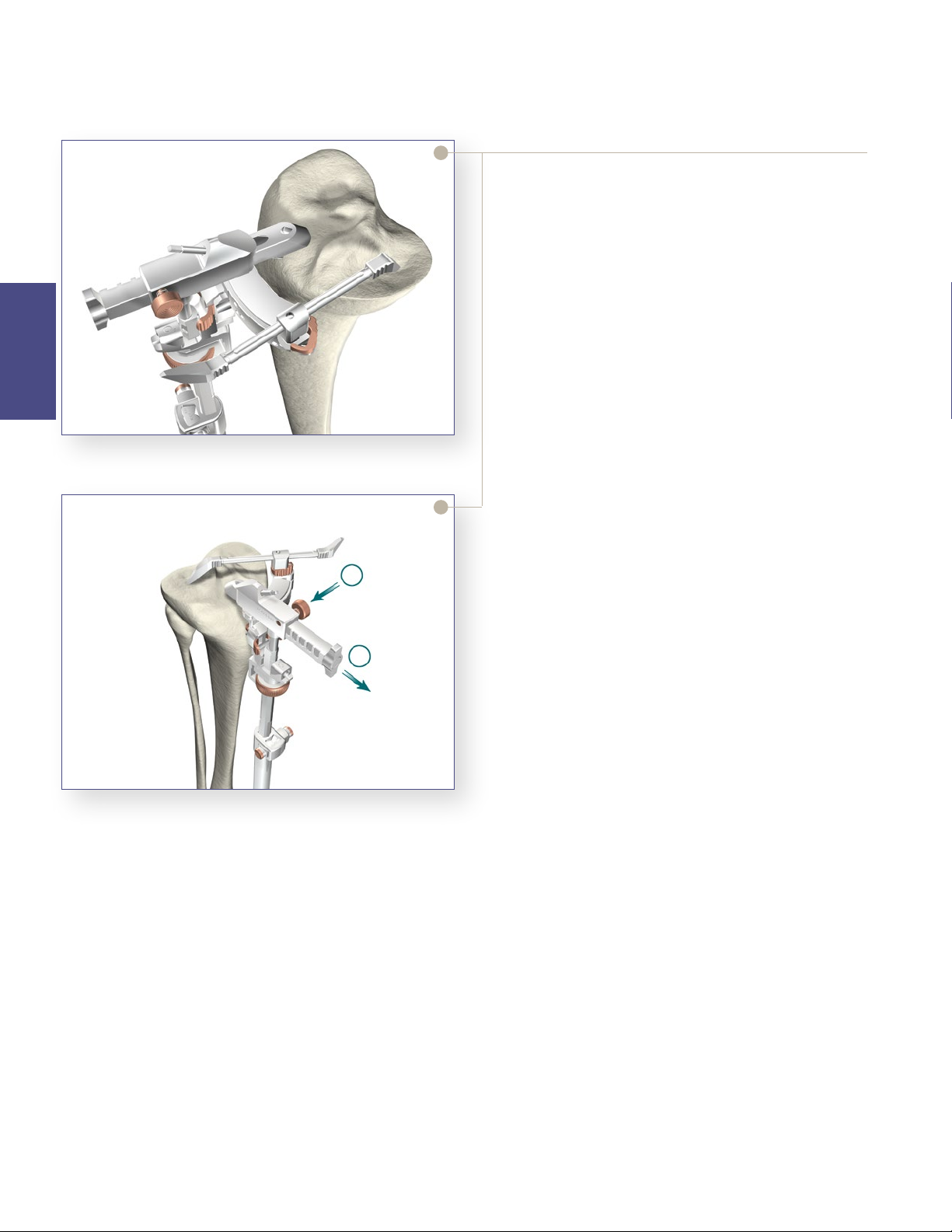
1
2
Establishing the Tibial Resection Level
> Once the tibial assembly is xed in place, the tibial
resection level must be established using the tibial
stylus. is attaches to the tibial resection guide
referencing either the lowest level of the aected
compartment or the highest level of the unaected
compartment. Typically, in a varus knee, the lateral
compartment is relatively unaected so placing the
“9” referencing end on the unaected lateral side
will insure at least a 9mm thickness for the tibial
component. If the surgeon desires a thicker tibial
component or if there is a defect on the medial side
of the tibia necessitating resection, further resection
can be made.
> To reference the lateral compartment, retraction of
the proximal rod arm is performed by pressing the
bronze button 1, and sliding the arm away from
the knee 2.
> Alternatively, by placing the tibial resection guide
with the “2” referencing end, the resection carried
out would be 2mm lower then the point chosen.
For a coarse gross adjustment, the bronze wheel can
be pressed and the assembly slid up or down. For
the nal ne adjustment, the bronze wheel is turned
to the right to move the assembly up the proximal
rod or turned le to move the assembly down the
proximal rod.
Figure 6
Tip: When using the stylus, it is important to make
sure the construct is under tension. is will help
ensure adequate resection levels.
> Once the nal position is chosen, two headless pins
are drilled into the “0” neutral holes securing the
level of the tibial resection guide. For additional
stability, the oblique “X” pinhole can be utilized.
Once the tibial resection guide is secured, all
alignment instruments are removed.
8
Instrument Bar
6541-2-610
Tibial Alignment Distal Assembly EM
6541-2-609
Tibial Alignment Ankle Clamp EM
6541-2-429
Tibial Stylus
Tibial
Preparation
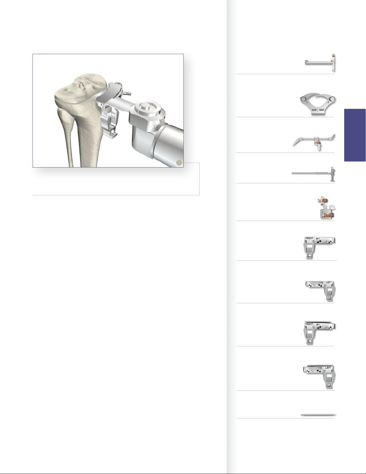
Figure 7
Final Tibial Resection
> Once all alignment instruments are removed leaving
the tibial resection guide in place, the proximal tibia is
osteotomized using either the right or le captured or
uncaptured tibial resection guide. If the entire resection
cannot be completed, the guide is removed and the
resection completed free-hand. Care must always be
taken not to injure the patella tendon, neurovascular
structures, or collateral ligaments. Oen some bone is
le unresected near the posterior aspect of the lateral
tibial plateau and the anterior aspect of the lateral tibial
plateau near Gerdy’s tubercle. Once the resection guide
is removed, nal resection can be completed either with
an oscillating saw, bone le or a rongeur.
Note: Leaving the pins in place will allow for an additional
2mm or 4mm of tibial resection. e pins must be removed
prior to cutting the tibial keel.
6541-6-611
MIS Proximal Rod EM
0º slope 6541-2-704
3º slope 6541-2-705
Tibial Adjustment Housing
6541-6-700
MIS Uncaptured Tibial Resection Guide-Right
6541-6-701
MIS Uncaptured Tibial Resection Guide-Le
6541-6-702
MIS Captured Tibial Resection Guide-Right
6541-6-703
MIS Captured Tibial Resection Guide-Le
6541-4-003
Headless Pins - 3”
9
Triathlon® Knee System
Single-Use Instruments Surgical Protocol
Femoral Preparation
Femoral Intramedullary Alignment
> e Universal Driver allows for attachment of
all drills and pins. e Universal Driver may be
attached directly to a reamer, drill, or a Jacob’s
Chuck.
> Locate the IM drill hole; it is approximately 1cm
anterior to the femoral attachment of the posterior
cruciate ligament and slightly medial to the midline
of the distal femur.
> Identication of landmarks may be aided by
removal of osteophytes from the margins of the
Figure 8
Femoral
Preparation
intercondylar notch.
> Attach the
drill into the IM canal ensuring that the drill is
parallel to the sha of the femur. e rst diameter
will create a tight t around the IM Rod. If further
clearance is desired, continue to drill until the larger
step diameter opens the hole. is will allow the IM
canal to dictate the position of the rod avoiding the
need to “toggle” the drill to create clearance.
3
/
8” IM Drill to the Universal Driver and
Figure 9
Figure 10
> Attach the T-Handle Driver to the 5/
Insert the IM Rod into the MIS Femoral Alignment
Guide. e MIS Femoral Alignment Guide is
designed for use on either the le or right knee and
may be set between 2° and 9° of valgus (Note: this is
typically set between 5° and 7°). Set the instrument
to the desired angle by pulling back on the black
knob of the MIS Femoral Alignment Guide and
placing it in the appropriate notch. Advance the
rod, with attached guide, slowly up the IM canal
until the desired depth is reached ensuring that the
alignment guide is ush against the most prominent
condyle.
> Snap the MIS Distal Resection Guide onto the MIS
Adjustment Block and insert the posts of the MIS
Adjustment Block into the two holes in the MIS
Femoral Alignment Guide.
> Place the MIS Femoral Alignment Guide in contact
with the more prominent distal femoral condyle and
align the guide in neutral I/E rotation. e guide
face is angled at 3° and has a tick mark to reference
Whiteside’s Line to set I/E rotation, if desired.
> Insert
1
/
8” headless pins into the converging pinholes
on the MIS Femoral Alignment Guide to aid in
stabilization.
16” IM Rod.
10
Instrument Bar
6541-4-801
Universal Driver
6541-4-538
3/8” IM Drill
6541-4-800
T-Handle Driver
Button
Figure 11
> Position the leg in 45°-60° of exion.
> e MIS Adjustment Block allows for a 2mm through 12mm
resection level.
> Press the black button on the end of the MIS Adjustment Block
and push/pull the carrier to set the resection to the desired level.
6541-4-516
5/16” IM Rod
6541-5-629
MIS Femoral Alignment Guide
6541-5-721
MIS Distal Resection Guide - Le
6541-5-722
MIS Distal Resection Guide - Right
6541-5-601
MIS Femoral Adjustment Block
Femoral
Preparation
Figure 12
> e Triathlon MIS Knee System Instruments allow for a clear
view of the bone that is being resected to ensure the appropriate
level is set.
> Slide the Adjustment Block Assembly posteriorly within the
Femoral Alignment Guide until the Distal Resection Guide
contacts the anterior surface of the femur.
6541-4-003
Headless Pins - 3”
11
Triathlon® Knee System
Single-Use Instruments Surgical Protocol
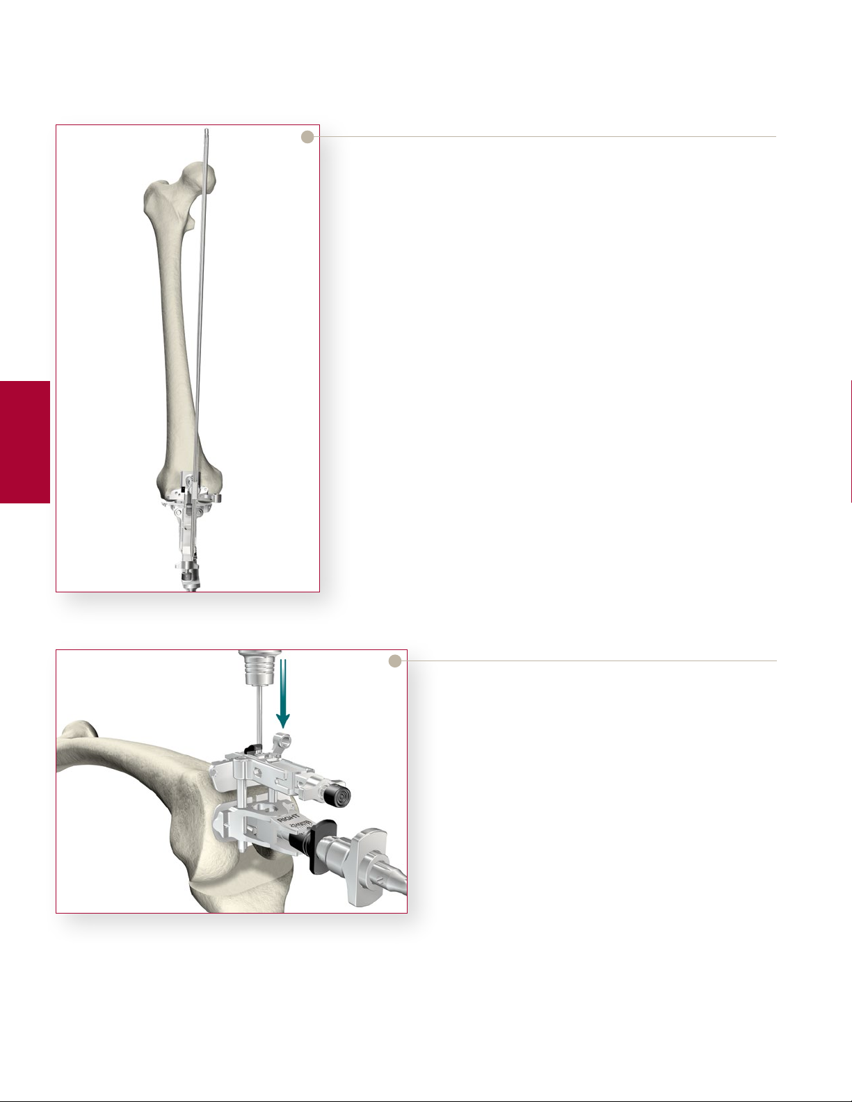
Optional Check
> Prior to pinning the Distal Resection Guide to the
femur, an optional external alignment check may
be performed. Attach the Femoral EM Alignment
Tower to the MIS Femoral Adjustment Block and
insert a Universal Alignment Rod into the handle.
> Alignment is correct when the rod intersects the
center of the femoral head and roughly parallels the
axis of the femur in the lateral view.
> Once satisfactory alignment is achieved, remove the
Femoral EM Alignment Tower and the Universal
Alignment Rod.
Femoral
Preparation
Figure 13
> Pin the Distal Resection Guide to the anterior
femur using Headless Pins. Insert the pins into
the Headless Pin Driver (which is inserted into the
Universal Driver) and drill through the set of holes
marked “0” on the Distal Resection Guide. e pins
are automatically released from the driver as it is
pulled back.
Note: Ensure that 1/2” of the pin is protruding from all
guides aer insertion. is will aid in pin removal.
12
Figure 14
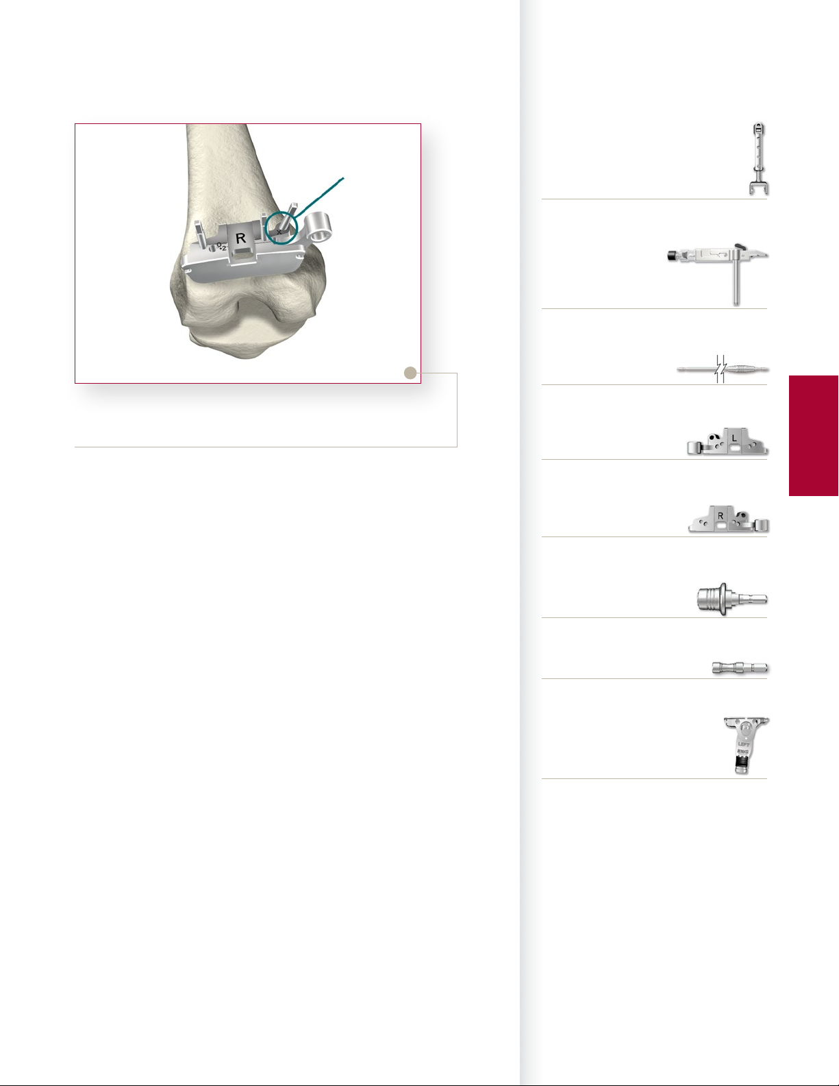
“ X”
Pin-hole
Figure 15
Instrument Bar
6541-7-808
MIS Femoral EM Alignment Tower
6541-5-601
MIS Femoral Adjustment Block
6541-4-602
Universal Alignment Rod
> Pinning through the “X” pin hole will aid in further
securing the guide.
> Aer the Distal Resection Guide is pinned in place,
remove headless pins from the Femoral Alignment
Guide and remove the IM rod. e Femoral
Alignment Guide and the Adjustment Block may be
removed by pressing the black button on top of the
Adjustment Block.
6541-5-721
MIS Distal Resection Guide - Le
6541-5-722
MIS Distal Resection Guide - Right
6541-4-801
Universal Driver
6541-4-809
Headless Pin Driver
6541-5-629
MIS Femoral Alignment Guide
Femoral
Preparation
13
 Loading...