

Page 1

IMPORTANT INFORMATION: File this in your TPS records
Total Performance System Consoles
REF 5100-1 & 5100-1A Console
REF 5100-50 & 5100-50A Irrigation Console
User's Guide
••••••••••••••••••••••
Includes setup, safety, repair, and warranty information for the
Stryker Total Performance System.
For answers to questions about other equipment, see the
information supplied with that equipment.
V e r s i o n
4.x
US Patents D398,598; D415,134; 5,543,695; 5,689,159; 6,017,354; 6,025,683;
6,045,564; 6,329,778 and other patents pending
5100-001-709 Rev-F10/05
1
4100 E. Milham
Kalamazoo, Michigan
(USA) 49001
1-800-253-3210
1-269-323-7700
www.stryker.com
European Authorized Rep:
RA/QA Manager
Stryker France
ZAC Satolas Green Pusignan
Av. de Satolas Green
69881 MEYZIEU Cedex
France
Page 2

Contents
Software License Notice....................................................................................3
Where to Find Answers ..................................................................................... 4
Warning, Caution, Note Defined .........................................................................4
Important Safety Instructions ............................................................................. 5
System Overview
Symbol Definition ............................................................................................. 6
Operating Instructions
Connecting the Equipment ................................................................................7
The Control Screen
TPS Start-Up Screen
No Handpiece Detected Screen ..........................................................................8
Functions of the Control Screen
Elements of the Control Screen ..........................................................................9
Select Your System Settings
Standard Features ......................................................................................... 10
Quick Reference Guide (Icon Definition) ............................................................. 11
Handpiece Screens
Saw Handpiece Screen (TPS Oscillating and Sagittal Saws) ........................................... 12
Rotary Handpiece Screen
(TPS Universal and MicroDrills & TPS MicroDriver) ........................................................... 13
Stryker Endoscopy and Leibinger Handpiece Screen
(SE5 hand-controlled Endo Shaver, QuadraCut Shaver, QuadraCut Bone Plug,
and QuadraCut Small Joint, Hummer 4, Formula, 6K Micro, 12K Micro) .........................14
Other Screens
Main Option Screen ........................................................................................ 15
System Information Screen .............................................................................. 16
Handpiece Adjustment Screen ......................................................................... 17
Console Adjustment Screen ............................................................................. 18
Footswitch Adjustment Screen ......................................................................... 19
Footswitch Button Mapping Screen .................................................................. 20
Handpiece Button Mapping Screen................................................................... 21
Surgeon Preference Screen ............................................................................. 22
Messages and Error Messages ........................................................................ 23
Specifications................................................................................................ 24
Compliance Statements .................................................................................. 24
Declaration of Conformity ............................................................................... 25
Guidance and Manufacturer's Declarations .................................................... 26-28
Repair/Loaner Program
Limited Warranty ............................................................................................ 29
2
Page 3

Software License Notice
Stryker® TPS™ Surgical Tool System products contain software that is installed in the products by Stryker Corporation. Stryker Corporation owns
this software; this software is never sold. Each sale of a software containing product is not a sale of such software; it includes only a license to use
the software in the product in which the software was initially installed.
Any license granted by Stryker Corporation to use the software contained in its; products does not give the licensee the right to copy, alter,
disassemble, reverse engineer, create derivative works of such software or to use such software in either original or modified form in any product
other than the Stryker Corporation product in which the software was initially installed by Stryker Corporation.
© 2003, Stryker Corporation
3
Page 4

Where to Find Answers
When you have questions about your Stryker TPS products, there are several places to find the
answers.
In this book
Use this book to set up your system and select console options. This book also contains
information on system safety, repair, and component warranty.
............................................................................................................................................
In TPS component instructions
For answers to questions about any TPS handpiece, attachment, or component , see
the information supplied with that component. A copy of TPS Cleaning, Maintenance and
Sterilization Recommendations is also supplied with each component.
............................................................................................................................................
From your Stryker Sales Representative
If you can't find an answer in any of the materials provided or you have questions about
other Stryker Instruments products, call your Stryker Sales Representative.
............................................................................................................................................
From Stryker Customer Service
Please contact our Customer Service Department to order product information literature, a
cutting accessories guide, additional TPS maintenance manuals, and component instructions
by dialing 1-800-253-3210. Outside the U.S.A., contact your nearest Stryker subsidiary.
............................................................................................................................................
See the TPS Cleaning, Maintenance, and Sterilization Recommendations
booklet for care information.
Warning • Caution • Note
This symbol is used to alert the reader to important safety and precautionary information. When
displayed on the actual device, it refers the user to accompanying documents.
Please read this manual and follow all instructions carefully. The words WARNING, CAUTION and NOTE
carry special meanings and should be carefully reviewed.
WARNING: The personal safety of the patient and/or user may be involved. Disregarding this information
could result in injury to the patient and/or operating room staff.
CAUTION: These instructions point out special service procedures or precautions that must be followed
to avoid damaging the instrument.
NOTE: This provides special information to make maintenance easier or important instructions more
clear.
4
Page 5

IMPORTANT SAFETY INSTRUCTIONS
WARNING: The personal safety of the patient and/or user may be involved. Disregarding this information could result in injury to
the patient and/or operating room staff. Read and understand the following warnings.
SYSTEM SAFETY
▪ Prior to each use, operate system components and inspect for
damage. DO NOT use if damage is apparent. Take special precautions regarding electromagnetic compatibility (EMC) when using
medical electrical equipment like the TPS Console. Install and
place the console into service according to the EMC information in
this manual. Portable and mobile RF communications equipment,
such as wireless phones, can affect the function of the console.
▪ Use only Stryker approved accessories. Other accessories may
result in increased emissions or decreased immunity of the system.
Contact your Stryker sales representative for a complete list of accessories. DO NOT modify any accessory. Failure to comply may
result in patient and/or operating room staff injury.
▪ DO NOT modify ground of power cord.
▪ Equipment not suitable for use in the presence of flammable anes-
thetic mixture with air or with oxygen or nitrous oxide.
▪ The Stryker Total Performance System is designed to be used by
persons familiar with surgical procedures. Misuse may cause injury
to both patient and system components. Prior to each use, system
components should be inspected for damage. DO NOT use if damage is apparent.
▪ Use only Stryker TPS components and accessories unless other-
wise specified.
▪ Clean and sterilize handpieces and accessories before first and
every use.
▪ Use of safety glasses by user and operating room staff is recom-
mended to prevent eye injuries.
HANDPIECE SAFETY
▪ Read this booklet and the information supplied with your TPS
components. Component instructions provide specific safety
information. Refer to the instructions supplied with Stryker
Endoscopy handpieces when using those handpieces in conjunction with the TPS console.
▪ DO NOT attempt to change a saw, bur, or drill while handpiece is
running.
▪ Stryker handpieces which fail due to long life and/or nose bearing
failure may allow foreign matter to migrate or emit from the distal
tip of the handpiece.
Fluid may leak into the surgical site, such that measures may be
required, per the physician's discretion, to protect the patient from
infection.
▪ Never rest handpiece on the patient. Improper handling of a hand-
piece could result in damage or burns to tissue.
▪ Do not place a TPS handpiece near or on a magnetic pad or tray.
The magnetic field can simulate a Universal Handswitch and may
cause the handpieces to run inadvertently.
▪ Burs and blades are intended for single use only.
▪ Excessive pressure, such as bending or prying, may cause acces-
sory to bend or break and cause tissue damage to patient and/or
operating room staff.
▪ Heavy sideloads and/or long operating periods occasionally will
cause overheating of the distal tip and the body of handpieces to
the point where the handpiece is uncomfortable to hold or causes
injury to the patient.
▪ If the recommended duty cycle is not followed, the handpiece may
overheat and cause injury to patient and/or operating room staff.
See the Duty Cycle information supplied with each handpiece.
▪ Excessive pressure, such as bending and/or prying with a bur, may
cause the bur to bend or fracture. If operated at a high speed, it is
possible that the bur will bend yet further. This could result in damage to tissue in the surgical site, handpiece vibration that causes
lost tactile control, or breakage of the bur such that the broken
piece would be ejected at a high velocity endangering the patient
and/or operating room staff. It is therefore recommended that
safety glasses be used.
▪ Excessive pressure, such as bending and prying with blade, may
cause the blade to bend or fracture and could result in damage to
tissue in the surgical site and/or loss of tactile control.
▪ If using a device with a safety lock, such as a MicroDriver or
Universal Handswitch, always place that device in the SAFE position
when not in use. IMPORTANT: Be aware that the TPS footswitch
will override the Universal Handswitch SAFE setting.
▪ Always use the appropriate accessory combination with a hand-
piece. Contact your Stryker sales representative for a complete
list of accessories. Failure to comply may result in patient and/or
operating room staff injury.
▪ Please note the handpiece starts with rapid acceleration when the
footswitch or handswitch is activated.
▪ During initial use of your TPS handpieces, monitor the heat
response in relation to the type of surgical procedure being
performed. Frequently check the distal tip and body until you are
familiar with its temperature rise characteristics. Failure to pay
close attention to handpiece temperature may cause burn injury to
patient.
▪ Operating a handpiece in the Window Jog mode may cause the
handpiece to overheat. If a handpiece overheats, the console
automatically turns off the handpiece. (The alarm does not sound
in this event.) Carefully monitor the operating time to prevent the
handpiece from overheating. Failure to comply may cause injury to
the patient and/or the operating room staff.
▪ DO NOT modify any bur to fit the handpieces. Use only Stryker
approved burs. Other burs may not fit properly in the handpiece.
During use they may come out of the handpiece or bend which
would result in damage to tissue in the surgical site due to loss of
control of the bur.
5
Page 6
System Overview
The Stryker Total Performance System is intended for use in the cutting, drilling, decorticating, and smoothing of bone and other
bone related tissue in a variety of surgical procedures. It is also used for the placement or cutting of screws, wires, pins, and other
fixation devices as it can be used to cut metal.
TPS console powers multiple handpieces while allowing the user to program a number of customized settings.
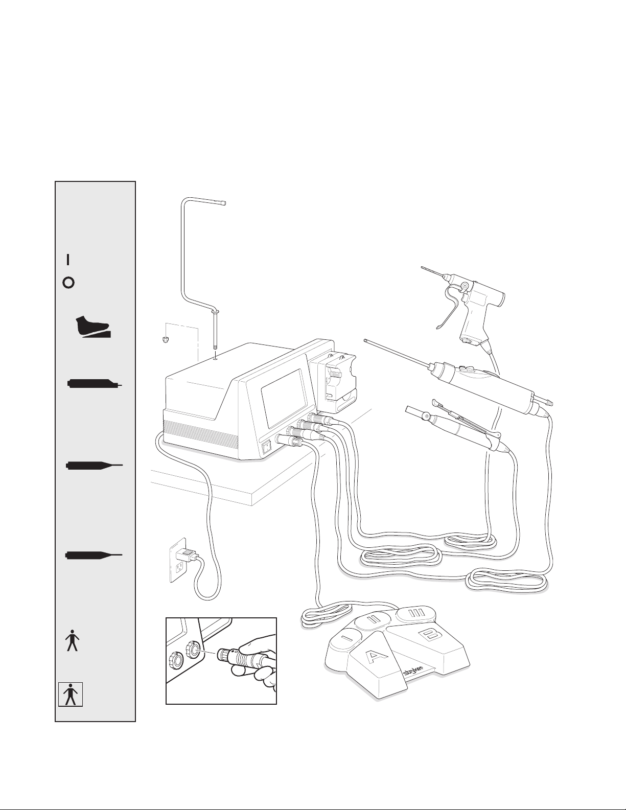
Symbol
Definition
Power ON
Power OFF
Footswitch
Connector
ENDO
Endoscopy
Handpiece Port
TPS1
TPS Handpiece
Port 1
TPS Handpiece
TPS Irrigation Console
Stryker Endoscopy
Handpiece
TPS Handpiece
with Universal
Handswitch
Handpiece
Cords
TPS2
TPS Handpiece
Port 2
Type B
Applied
Part
Type BF
Applied
Part
TPS Footswitch
Connection Detail
6
Page 7

Operating Instructions
WARNINGS:
▪ Before using this system read and understand the information in this manual and the instructions supplied with each TPS
component and Stryker Endoscopy handpieces. Pay close attention to the User/Patient Safety Information.
▪ Familiarization with the Total Performance System prior to use is important. If you have any questions, contact your Stryker
Instruments representative or Stryker Customer Service at 1-800-253-3210.
▪ Prior to use, system components should be operated and inspected for any damage. DO NOT use if damage is apparent.
Connecting the Equipment
This is a system overview. For specific instructions on each TPS component, refer to the
information supplied with the component.
1. Place your console on a sturdy, flat surface near a hospital grade outlet.
2. Plug the console's power cord into the recessed power socket on the back of the
console.
3. Plug the other end of the power cord into a hospital-grade wall outlet.
4. Turn on the console. The on/off switch is located on the front of the console.
NOTE: As you set up the system, the console's screen will change to indicate the various
components as they are plugged in.
5. If using a Footswitch, plug the footswitch cable into the console port marked
FOOTSWITCH. Align orientation marks and gently push connectors together.
CAUTION: All TPS Cords have push/pull connectors. Do not thread or twist for insertion or
removal.
6. Plug the handpiece cord(s) into the console port(s) identified for the handpiece. Align
connector orientation marks and gently push connectors together.
NOTE: Ports marked TPS1 and TPS2 are for Stryker TPS handpieces only.
The port marked ENDO is intended for the following list of Stryker Endoscopy handpieces:
SE5 Handpiece REF 272-704-100, SE5 Hand-controlled REF 272-704; QuadraCut Shaver
REF 275-701; QuadraCut Bone Plug REF 275-705; and QuadraCut small Joint REF 275-
601.
NOTE: If using a TPS Universal Handswitch, attach it to the handpiece before you plug the
cord into the handpiece.
WARNINGS:
▪ Portable and mobile RF communications
equipment can affect the TPS Console.
▪ The TPS Console should not be placed
adjacent to or stacked with other
equipment. If adjacent to or stacked, the
equipment must be observed to verify
normal operation.
7. Plug the other end of the handpiece cord(s) into the handpiece(s).
8. Attach cutting accessories to handpieces. Instructions supplied with each handpiece or
attachment provide details for cutting accessory assembly.
WARNING: Use only Stryker approved cutting accessories.
9. If using an Irrigation Console REF 5100-50, assemble Irrigation Pole REF 5100-50-28 to
the console as shown. Hang irrigation bag from pole. Install irrigation cassette into the
pump. Attach irrigation clips to handpieces and connect tubing.
10. Power the system and test the devices to ensure they are performing properly prior to
surgery.
7
Page 8
The Control Screen
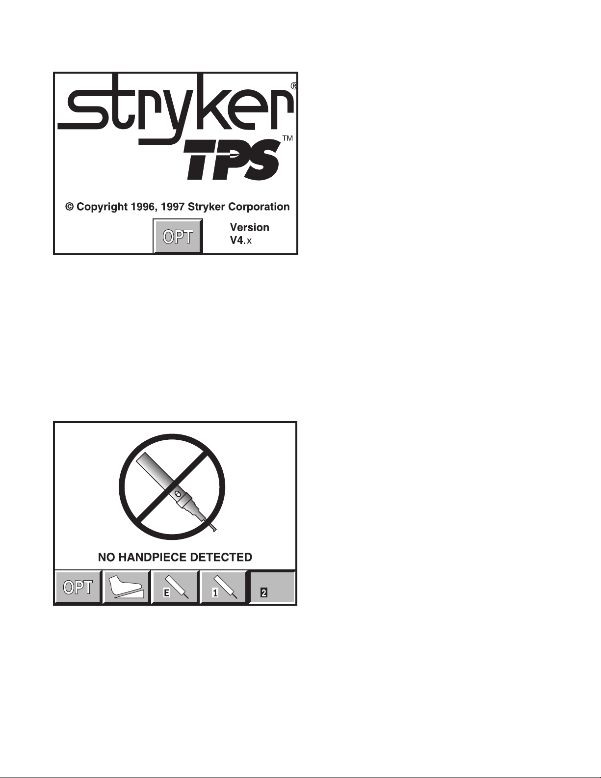
TPS Start-Up Screen
This display appears on the screen every time the
console is turned on.
This display remains on the screen until a cord is
plugged into one of the TPS handpiece ports or the
OPT button is depressed.
If a handpiece cord is plugged into a handpiece port
when the console is turned on, this display shows
momentarily before changing to either a no handpiece
detected screen or to the screen of the selected
handpiece.
This example shows that no handpiece is attached to the cord plugged into the
TPS2 port.
No Handpiece Detected Screen
This image indicates that no handpiece is attached to
the cord plugged into the selected port. The screen
will change to the handpiece screen when the missing
handpiece is connected to the cord.
NOTE: This screen will also appear if the console
is unable to recognize the handpiece. This could be
caused by a handpiece that is not compatible with the
TPS console, or a faulty or damaged handpiece or
cord.
8
Page 9

Functions of the Control Screen
The TPS console allows the user to select functions and settings such as handpiece selection, speed, and direction. Designed to
be easy to use and understand, the touch sensitive control screen allows you to set the system controls with the touch of a finger.
Interactive icons on the control panel represent system components and functions. The control screen also provides important
monitoring information for the selected handpiece.
Surgeon
Handpiece
identification
Attachment/
Blade
identification
preference
indicator
Handpiece
speed
Handpiece power
Indicator ramp
Select system
options screen
Footswitch
indicator and
options
Elements of the Control Screen
Control screen visually presents options which can be set for
the selected handpiece.
Icons represent elements of your TPS system. Icons are
functional buttons. Each function may be selected by pressing
the screen where the button is displayed. When you touch an
icon, the icon appears to be pressed down and the graphic
symbol highlights to indicate that it is activated. (See Icon
Definition).
NOTE: An audible signal indicates interface with icons.
NOTE: Buttons such as the adjust arrows or OPT button which
are temporary toggles or adjustment buttons only highlight while
depressed.
NOTE: Buttons with a white background are toggle buttons.
NOTE: Options vary among different handpieces. The console
will only display the options available for a given handpiece.
TPS handpiece
select buttons
Endo handpiece
select button
Handpiece identification displays the name of the active
handpiece. NOTE: Handpieces can be plugged into each of
the console's handpiece ports, but only one can be selected at
a time.
NOTE: When *CUSTOM* is displayed at the top of the screen,
the console's default settings are selected from Surgeon
Preferences. The console is able to capture the preferred
settings for several different users. When this feature is
activated, the preferred settings act as default settings. See
Surgeon Preference for further details.
Handpiece speed information displays the default speed for
each handpiece until you reset speed settings.
While the handpiece is running, the display shows the actual
handpiece speed. If the handpiece is not running the default or
selected speed is displayed.
NOTE: Incremental information displayed on the control screen is
accurate within +/-1%.
9
Page 10

Select Your System Settings
NOTE: When the console is turned on, its default setting
is factory default unless a Surgeon Preference setting is
selected as the start up default. See Surgeon Preference for
further details.
1. Handpiece select buttons enable you to activate the
handpiece plugged into one of the three ports on the
front of the console. To display the control screen for
the handpiece plugged into the TPS1 port, touch the
corresponding handpiece select icon. The icon highlights
and appears pressed down.
NOTE: Selecting a handpiece icon activates the
corresponding handpiece and displays its specific control
screen.
Standard Features
Main Option Icon
The option icon appears on all handpiece screens
and allows access to the MAIN OPTION screen. See
MAIN OPTION SCREEN for further details.
Footswitch Icon
2. Change the maximum handpiece speed. Press the
adjustment arrows to change the handpiece speed setting
incrementally until the desired speed is reached.
• Saws - The set point is displayed as a percentage of
maximum power and vertical line on the speed ramp. During
handpiece operation, the percentage reading and speed
ramp displays the power level.
• Rotary handpieces - The speed set point is displayed.
During handpiece operation, the current speed is displayed.
3. Select various settings as desired. Refer to the control
screens on the following pages for details for each
handpiece.
4. Select the OPT icon to access the MAIN OPTION screen.
This screen allows access to general console and user
settings as well as direct access to each handpiece option
screen.
NOTE: The screen returns to the active handpiece
adjustments screen when the handpiece name is touched.
5. Touch the EXIT icon to return to the active handpiece
control screen.
The footswitch icon only appears when a footswitch
is plugged into the console.
If using a footswitch with these graphics,
pedal functions can be reprogrammed.
See Footswitch Adjustments and Footswitch
Button Mapping.
A footswitch with these graphics
cannot be reprogrammed.
Handpiece Irrigation
Irrigation functions pertain only to Irrigation Console REF
5100-50.
Press the icon to start irrigation flow while the
handpiece is running.
If irrigation is desired while the handpiece is stopped, press and
hold the icon until the pump is activated. The pump can be turned
off by touching the icon again.
Irrigation flow rate can be adjusted from the HANDPIECE screen
or the HANDPIECE ADJUSTMENTS screen.
From the HANDPIECE screen, toggle the SPEED
icon to WATER before using the arrows to adjust
flow rate.
-OR-
From the HANDPIECE ADJUSTMENTS screen, select
the WATER icon and use the arrows to adjust flow
rate. Flow rate diminishes as the setting approaches
zero.
NOTE: Flow rate may vary among handpiece
models.
The pump can also be turned on and off with the footswitch.
10
Page 11

Quick Reference Guide
Icon Definition
Handpiece Select
This type of icon appears when
a cord (without a handpiece) is
plugged into the corresponding
Endo, TPS1 or TPS2 port.
It appears depressed when
selected.
The handpiece graphic appears
when a handpiece is attached to
the corresponding cord.
The handpiece graphic highlights
and the icon appears depressed
when selected.
System Options
Options: Gives access to
handpiece adjustments, system
information, console adjustments
and user preference.
Exit: Returns to previous screen.
Information: Displays system
information screen.
Console: Gives access to console adjustment screen.
Handpiece
option: Accesses
corresponding
handpiece adjustment
screens.
Footswitch Icon: Appears when
a footswitch is connected to the
console. Also gives access to
footswitch adjustments screen.
Adjustment Arrows: Use in conjunction with
other options to set handpiece speed or
power, braking, acceleration, irrigation flow,
screen contrast etc.
Increase
Decrease
Direction Arrows: Sets handpiece mode.
Forward (clockwise)
Reverse (counterclockwise)
Oscillate
Irrigation: Activates or de-
activates handpiece irrigation.
High: Enables handpiece to operate in a high speed mode.
Low: Enables handpiece to operate in a low speed mode.
Toggle Buttons
NOTE: For easy identification, only toggle buttons have a white background.
Speed: Use with the increase and
decrease icons to adjust rotary
handpiece speed.
Water: Use with the increase and
decrease icons to adjust irrigation
flow.
Power: Use with the increase
and decrease icons to adjust saw
power.
Variable: Handpiece speed
responds to varying degrees of
pressure on the footswitch or
handswitch.
Nonvariable: Handpiece operates
at constant set-point speed/power
level.
One touch: Handpiece is activated
by one touch of a trigger device
and continues to run when the trigger device is released. Handpiece
is deactivated by touching any
trigger device. In this mode, the
handpiece operates at constant
set-point speed/power level.
Allows access to the surgeon
preference screen.
NOTE: TPS Console REF 5100-1 does not display options related
to handpiece irrigation.
11
Advanced: - Accesses the
advanced footswitch mapping
screen.
Button: Access button mapping
screen.
Return to full screen: Return
from Big to full handpiece screen.
Page 12

Saw Handpiece Screen
TPS Oscillating and Sagittal Saws
POWER/WATER ADJUSTMENT
The power icon functions as a toggle switch
for power and water settings.
Power and irrigation adjustments are made
using the adjustment arrows.
As the power setting is reduced from 100%, a vertical bar
displays to correspond to the lower selected maximum
power.
This screen appears when a TPS saw is selected at the TPS1 port with the maximum
power set at 100%.
ENDO, TPS2 and the footswitch icons indicate other instruments are plugged into the
console.
The irrigation setting is not displayed on this screen.
However, it can be seen on the Handpiece Adjustments
screen.
METHOD OF OPERATION
Saws can be operated with the TPS Universal Handswitch
or TPS Footswitch.
Handswitch Handpiece selection can be made by
depressing the handswitch once. The handpiece select
icon changes to indicate the active handpiece. Depress
the handswitch again to run the handpiece.
Handpiece runs from start-up to the maximum selected
speed.
Footswitch Handpiece runs from start-up to the maximum
selected speed with either the forward or reverse pedal.
12
Page 13

Rotary Handpiece Screen
This screen appears when a TPS rotary handpiece is selected. The TPS Universal Drill is
plugged into the TPS2 port and the speed is set at 75,000 RPM.
ENDO, TPS1 and the footswitch icons indicate that other instruments are plugged into the
console.
SPEED/WATER ADJUSTMENT
The speed icon functions as a toggle switch
for speed and water settings.
Speed and irrigation adjustments are made
using the adjustment arrows.
DIRECTION OPTIONS
FORWARD Clockwise
REVERSE Counterclockwise
OSCILLATE
TPS Universal and Micro Drills
METHOD OF OPERATION
The Universal Drill can be operated with the TPS Universal
Handswitch or TPS Footswitch.
Handswitch Handpiece selection can be made by depressing the
handswitch once. The handpiece select icon changes to indicate
the active handpiece. Depress the handswitch again to run the
handpiece.
Handpiece runs from start-up to the maximum selected speed.
Speed and cutting direction corresponds to what is selected on the
screen.
Footswitch Handpiece runs from start-up to the maximum
selected speed.
Handpiece direction is controlled by selecting the forward or
reverse pedals. The direction icon on the screen changes when
the corresponding footswitch pedal is depressed.
TPS MicroDriver and Universal Driver
METHOD OF OPERATION
The TPS MicroDriver can be operated with its builtin trigger and rotary control switch or with the TPS
Footswitch.
NOTE: The handpiece will not run when the rotary switch
is in the SAFE position.
Trigger The built-in speed control trigger(s) runs the
handpiece from start-up to the maximum selected speed.
MicroDriver only: Select cutting direction with the rotary
switch on the handpiece. Direction icon will highlight to
match the rotary switch position.
Universal Driver only: Select cutting direction by
depressing either the forward trigger or the reverse
trigger. Squeezing both triggers simultaneously runs the
handpiece in the oscillate mode. The oscillate icon will
become highlighted.
Footswitch Handpiece runs from start-up to the
maximum selected speed.
The direction icon on the screen changes when the
corresponding footswitch pedal is depressed.
Footswitch operation overrides handpiece settings.
Example: If the footswitch reverse pedal is depressed
while the handpiece rotary switch is set in forward,
the handpiece operates in the reverse direction and
the reverse icon highlights. However, after the pedal is
released, the direction icon will revert to the direction set
on the rotary switch.
13
Page 14

The Stryker Endoscopy and Leibinger Handpiece Screen
This screen displays the cutter nomenclature only if the
handpiece and cutter being used contain cutter recognition
capabilities.
Depress the mode icon and set the maximum speed using
the adjustment arrows. Speed settings are individually
selected for each mode.
Default speed settings and incremental steps are specific to
each handpiece.
MODES
Operation in high speed mode.
This screen appears when a Formula handpiece with cutter recognition is selected. The
oscillate mode is selected and Set Speed is set at 1,800 RPM.
TPS1, TPS2 and the footswitch icons indicate that other instruments are plugged into the
console.
The Stryker Leibinger Hummer4 REF 5290-601-100 and Stryker
Endoscopy Formula REF 375-701-500 provide cutter recognition
capabilities.
WARNING: Read and understand the
Stryker Endoscopy handpiece instructions.
If instructions were not supplied with your
handpiece, refer to the appropriate Stryker
Endoscopy Operating and Maintenance Manual
listed below.
Handpiece Manual
272-704 1000-400-120
275-701 1000-400-034
275-705 1000-400-034
275-601 1000-400-034
290-601 1000-400-288
IMPORTANT INFORMATION
The hand-controlled Endo Shaver can be
controlled by the footswitch or by the hand-control
buttons built into the handpiece.
Operation in oscillate mode.
Operation in low speed mode.
When a cutting accessory with cutter recognition
capabilities is installed, the system may override selected
speed settings within each mode to more appropriate speed
settings for that particular cutting accessory.
The handpieces listed here do not have cutter
recognition capabilities.
14
Page 15

Main Option Screen
Select the OPT icon to access the MAIN OPTION screen.
This screen allows direct access to the handpieces attached
to the console, console and user settings, and system
information.
OPTION 1, 2, and E icons appear only when handpieces are
plugged into the corresponding console ports. A handpiece
must be plugged in to program its settings.
To go to the HANDPIECE ADJUSTMENT screen, touch the
option button that corresponds to the desired handpiece.
Refer to HANDPIECE ADJUSTMENT.
The MAIN OPTION screen also gives DIRECT access to:
Refer to SURGEON PREFERENCE.
Refer to CONSOLE ADJUSTMENT.
Refer to SYSTEM INFORMATION.
EXIT: Return to handpiece screen.
15
Page 16

System Information Screen
Selecting the INFO icon from the MAIN OPTION menu
displays the part numbers and revision levels of the
configured system components.
This information is used as a diagnostic aid only.
Return to the MAIN OPTION screen.
16
Page 17

Handpiece Adjustment Screen
Select a Handpiece Option icon from the MAIN OPTION
screen to access this screen.
NOTE: For quick access to this screen, touch the handpiece
title displayed at the top of any handpiece screen. And return
to the handpiece screen by touching the handpiece title displayed on this screen.
Depending on the type of handpiece, one or more of the
following options will be available.
Select BRAKE, ACCEL, TURNS or WATER then press the
arrow icons to change the setting.
Brake: At 100%, the handpiece stops abruptly.
Deceleration slows as the setting nears zero.
Accelerate: At 100%, handpiece speed accelerates
quickly. Acceleration slows as the setting
approaches zero.
Turns: Use to set the number of turns per direction
when running a handpiece in the oscillate mode.
The minimum setting will set the oscillate function
to operate in a TIME-BASED mode where the
number of turns are based on the speed of the
handpiece.
ATTACHMENT: Use the arrow icon on the left to scroll
through the list of attachments. Select the attachment that is
assembled to the handpiece by stopping on it.
Selecting the proper attachment will optimize the performance
of the handpiece for the attachment and display the appropriate
speed scale on the handpiece screen.
RUN MODE: Use the RUN MODE toggle button to scroll
through the options and stop on the desired setting.
Variable: Handpiece speed responds to the degree
of pressure applied to the handswitch.
Nonvariable: Handpiece speed runs at the
maximum setting only. Varying pressure on the
handswitch does not vary the handpiece speed.
One touch: Toggle the handpiece on and off with
a single touch of a trigger device. The trigger
device can be the handswitch or handpiece trigger
buttons.
BUTTON: See Handpiece Button Mapping.
Water: At 100%, irrigation volume is greatest.
Volume decreases as the setting approaches zero.
FOOTSWITCH: Activates FOOTSWITCH
ADJUSTMENTS. See Footswitch Adjustments.
17
Page 18

Console Adjustment Screen
Select the CONSOLE ADJUSTMENTS icon from the MAIN
OPTION screen to access this screen.
Select CONTRAST, BRIGHTNESS or VOLUME then press
the arrow icons to change the setting.
Contrast: Screen contrast lightens at
higher settings. The chosen setting
remains until reset.
Brightness: Screen brightness intensifies
at higher settings.
Volume: The audible signal is louder at
higher settings.
Use the BIG SCREEN toggle button to select one of the
following options.
Automatic: A big screen is displayed while the
handpiece is running and automatically returns
to the full screen when handpiece stops.
On: The big screen is continuously displayed.
It can be temporarily switched back to the
full screen by touching the Full Screen icon
which appears in the lower right corner of each
handpiece screen. See example of screens
below.
Off: The big screen option is turned off. Only a
full screen is displayed.
Example of full screen.
Example of big screen.
18
Page 19

Footswitch Adjustment Screen
This screen appears only when using a TPS Footswitch that is
Revision 3 or newer. See Standard Features.
NOTE: The Footswitch revision is displayed on the SYSTEM
INFORMATION screen.
Access this screen by selecting the Footswitch icon on the
HANDPIECE CONTROL SCREEN or HANDPIECE ADJUSTMENTS
screen.
NOTE: These footswitch settings function only for the handpiece
for which they were selected. The handpiece is identified at the top
of the screen.
From this screen, the default functions of footswitch pads A and B
can be reprogrammed to accommodate the surgeon's preferences.
The left and right toggle icons correspond respectively to
footswitch pads A and B. Press each icon to scroll through the
following function options and stop on the desired setting.
Off: Pedal is turned off.
Default: Footswitch defaults to the settings selected on
the handpiece screen.
Forward: Pedal setting default is overridden.
Pedal will provide handpiece rotation in the forward
(clockwise) direction.
Reverse: Pedal setting default is overridden.
Pedal will provide handpiece rotation in the reverse
(counterclockwise) direction.
Advanced: Use to access the Footswitch Button
Mapping screen. It will allow you to reprogram all the
footswitch pedals.
Return: Return to the previous screen.
19
Page 20

Footswitch Button Mapping Screen
Access this screen by selecting the ADVANCED icon on the
FOOTSWITCH ADJUSTMENTS screen. The default functions
of each footswitch pedal and button can be reprogrammed to
accommodate the surgeon's preferences.
Depending on the type of handpiece displayed at the top of the
screen, one or more of the following options will be available on
this screen.
The DIRECTION, OP MODE, and RUN MODE icons
correspond respectively to the two largest footswitch pedals.
Press each icon to scroll through the following function
options. And stop on the desired function setting.
DIRECTION
Pedal is turned off.
Footswitch defaults to the settings selected on the
handpiece screen.
Forward: Pedal setting default is overridden. Pedal
will provide handpiece rotation in the forward
(clockwise) direction.
Reverse: Pedal setting default is overridden. Pedal
will provide handpiece rotation in the reverse
(counterclockwise) direction.
OP MODE
Footswitch defaults to the settings selected on the
handpiece screen.
Handpiece operates in the high speed range.
Handpiece operates in the low speed range.
Handpiece operates in oscillate mode.
RUN MODE
Footswitch defaults to the settings selected on the
handpiece adjust screen.
Variable: Variable speed control. Speed responds
to varying degrees of pressure on the footswitch.
BUTTON FUNCTION
The I, II, and III icons correspond to the three small pads across
the top of the footswitch.
Button Function displays the active function of the
corresponding button.
Use the arrow icons to scroll through the functions and stop on
the desired setting.
See Button Functions listed on next page.
Reset all: Press to return all pedals and buttons
back to their default setting.
Reset: Press to return the selected footswitch
button back to its default setting.
Nonvariable: Handpiece operates at a constant
speed level determined by the maximum speed
selected from the handpiece screen.
One touch: The one touch function is similar to an
on/off toggle. Tap the footswitch to operate the
handpiece at the maximum speed selected from
the handpiece screen. Tap any trigger device
again to stop operation.
20
Page 21

Handpiece Button Mapping Screen
Access this screen from the Handpiece Adjustment screen.
Use it to change handpiece button functions.
Depending on the features of the handpiece, as many as
five buttons can be reprogrammed. Identify corresponding
button numbers by pressing the buttons on the handpiece.
When the handpiece button is selected, the corresponding
function is displayed on the screen. Use the arrow icons
to scroll through the function options. Stop on the desired
option. See the list below for a description of the options.
NOTE: Available options are handpiece specific.
BUTTON FUNCTIONS
Reset: Select to return a single button to its
default function.
Reset all: Select to return all buttons to their
default functions.
Return: Return to previous screen.
Button Function Description
Main trigger Starts handpiece in default direction
FWD trigger Starts handpiece in forward direction in
REV trigger Starts handpiece in reverse direction in
OSC trigger Starts handpiece in oscillate mode.
Speed increment Increments the set point speed.
Speed decrement Decrements the set point speed.
Water increment Increments the pump flow set point.
Water decrement Decrements the pump flow set point.
Water on/off Toggles the pump on/off button. If
and mode.
default mode.
default mode.
pressed and held, the pump can
be turned on without running the
handpiece. Once started, the pump
can be stopped by pressing the button
again or by starting the handpiece.
Button Functions List
Button Function Description
Osc <> High/low Toggles the run mode between oscillate and
high or low.
High <> Low Toggles the run mode between high and low.
Forward <> Reverse Toggles the running direction.
Change port Changes the active handpiece port.
Change attachment Scrolls through the attachment list for the
selected handpiece.
Pump flush Turns the pump on at the flush rate. Once
started the pump can be stopped by pressing
the button again or by starting the handpiece.
Make port active Makes the selected handpiece active.
Window jog Slowly rotates the inner cutter for positioning
within the outer cutter's window.
WARNING: Operating a handpiece in the Window Jog
mode may cause the handpiece to overheat. If a
handpiece overheats, the console automatically turns
off the handpiece. (The alarm does not sound in this
event.) Carefully monitor the operating time to prevent the
handpiece from overheating. Failure to comply may cause
injury to the patient and/or the operating room staff.
21
Page 22

Surgeon Preference Screen
Access the SURGEON PREFERENCE screen from the MAIN OPTIONS
screen.
The console is able to capture and store the preferred settings of
different surgeon's.
There are three options:
• Factory default settings
• Settings saved by a previous surgeon
• Collection and storage of new settings
Using factory settings
1. Use the arrows to obtain "Stryker" and "Factory Default."
NOTE: The EDIT, DELETE and padlock icons do not function while
factory default settings are selected.
Using the settings saved by a previous user
1. Use the arrows to select the surgeon and procedure.
2. Select LOAD. Screen returns to the MAIN OPTION screen.
3. Proceed with surgery.
Collect and store preferred settings
1. Select NEW. The editor screen will appear with the selected
surgeon's name.
2. To create a new procedure under this surgeons name, select
ENTER. Or if you wish to collect and store settings under a new
This is the key pad screen used to
enter the doctor's name and name of
procedure.
surgeon name, use the key pad to delete (DEL) the existing name
then key-in the new name. Upon completion, select ENTER.
3. Use the key pad to enter the procedure name.
4. Upon completion, select ENTER. The screen returns to the
SURGEON PREFERENCE screen.
5. Toggle padlock icon so that the padlock appears open.
6. Select LOAD.
7. Configure system settings.
8. Upon completion, return to the SURGEON PREFERENCE screen.
9. Toggle the padlock icon so that the padlock appears locked.
Padlock opened to gather preferences.
Padlock closed to store preferences.
NOTE: If the padlock icon remains in the unlocked position, the
selected settings will be continuously updated with current settings.
Select to add a surgeon name.
Select to change the doctor name and/or procedure.
NOTE: Toggle the UPPER/LOWERCASE pad on the editor
screen to select letter case.
Delete: Select to delete the currently displayed file.
Select and use with the open padlock to gather (load) new
preference settings.
Default: Using the arrows, scroll the SURGEON
PREFERENCE screen to the desired surgeon and
procedure settings before activating DEFLT. This selection
becomes the default power on setting for the system until
a different selection is made.
22
Page 23

Messages
Message If you select OK to this question:
Delete all the surgeon's procedures?
Change the name of all the surgeon's Procedures listed under the surgeon will be moved under
procedures?
Identical record found.
Maximum number of records exceeded. Please delete inactive records.
Initializing console hardware. Please wait.
Handpiece has reached recommended service interval. Please return for service at earliest convenience.
Handpiece does not support the selected preference. Default handpiece setting will be used.
Handpiece temperature has exceeded its nominal operating range and may cause burning.
Handpiece temperature has exceeded its operating range. Allow to cool before restarting.
Procedure name unspecified.
Ensure handpiece speed does not exceed specified attachment limitations. Failure to do so may result in user and/or patient injury.
Cutter/bur is not compatible with the current handpiece.
Cutter/bur has exceeded its life. Please replace with a new cutter/bur.
The surgeon ID and all procedures will be deleted.
the current surgeon's name.
Error Messages
Message Action to Take
Error 001. Console hardware fault detected. Return console to Stryker for repair.
Error 002. Console hardware fault detected. Turn unit off and on again. If problem persists, return
Contact your Stryker service representative. console to Stryker for repair.
Error 003. Console hardware fault detected. Turn console off and on again. If problem persists, return
Contact your Stryker service representative. console to Stryker for repair.
Error 004. Footswitch fault detected, right pedal will be disabled. Unplug Footswitch from console and plug in again.
Contact your Stryker service representative. If problem persists, return footswitch to Stryker for repair.
Error 005. Footswitch fault detected, left pedal will be disabled. Unplug Footswitch from console and plug in again.
Contact your Stryker service representative. If problem persists return footswitch to Stryker for repair.
Error 006. Footswitch unreadable. Unplug Footswitch from console and
Contact your Stryker service representative. plug in again. If problem persists,
return footswitch to Stryker for repair.
Error 007. Handpiece fault detected, handpiece triggers will be Unplug cord from handpiece and plug in again.
disabled. Contact your Stryker service representative. If problem persists, return handpiece to Stryker for repair.
Error 008. Handpiece unreadable. Unplug handpiece from console and plug in again.
Contact your Stryker service representative. If problem persists, return handpiece Stryker for repair.
Error 009. Handpiece requires additional console hardware. Call your Stryker Instruments sales representative.
Contact your Stryker service representative.
Error 010 Handpiece requires additional console hardware. Call your Stryker Instruments sales representative.
Contact your Stryker service representative.
Error 011 Handpiece requires additional console hardware. Call your Stryker Instruments sales representative.
Contact your Stryker service representative.
Error 012 Cutting accessory requires additional console hardware. See the instructions supplied with the cutting accessory.
The Total Performance System is not field repairable. In case of operating difficulties, Stryker products must be returned for maintenance or repair.
23
Page 24

Specifications
Models: 5100-1 & 5100-1A TPS Console
5100-50 & 5100-50A TPS Irrigation Console
Size: 11.8 in. [299 mm] width
7.0 in. [179 mm] height
9.0 in. [229 mm] depth
12.2 in. [310 mm] depth (units with irrigation pump)
Weight: 9 lbs. [4.1 Kg]
14.1 lbs. [6.4 Kg] (units with irrigation pump)
Electrical: 100-120VAC, 50-60Hz, 6.0A
220-240VAC, 50Hz, 3.0A
Approval:
CSA International
• UL 60601-1
• CAN/CSA-C22.2 No. 601.1 M90
• IEC 60601-1
Handling your console and equipment
• When setting up your console, place on a sturdy, flat surface, and
carefully follow all setup instructions.
• When connecting or disconnecting a cable, always hold the cable by
its connector (the plug, not the cord).
• Never force a connector into a port. If the connector and port do
not join with reasonable ease, they probably don't match. Make sure
that the connector matches the port and that you have positioned the
connector correctly in relation to the port.
• To ensure the longevity, performance, and safety of this equipment,
package in original package materials when storing or transporting.
If the console experiences sporadic electrical interference:
Class I
PORT TYPE SYMBOL
Endo B
TPS1 BF
TPS2 BF
IPX0 Ordinary Equipment
Protective Earth Ground
Duty Cycle: Continuous operation with
intermittent loading
Refer to cycle times defined in the
TPS handpiece instructions.
Environmental Conditions
These conditions apply to all components of the TPS system unless
otherwise specified in the information supplied with that device.
Environmental Conditions: Operation Storage and Transportation
Temperature:
Relative humidity:
Atmospheric Pressure:
• Turn off all electrical equipment not in use in the operating room.
• Relocate electrical equipment; increase spacial distance.
• Plug the TPS console and other operating room equipment into different
outlets.
Compliance Statements
Federal Communication Commission FCC ID: Q9R-5100
This device complies with Part 15 of the FCC Rules.
Operation is subject to the following two conditions:
(1) this device may not cause harmful interference, and (2) this
device must accept any interference received, including interference
that may cause undesired operation.
Note that FCC regulations provide that changes or modifications
not expressly approved by Stryker
Instruments could void your authority to operate this equipment.
24
Specifications listed are approximate and may vary slightly from unit to
unit or by power supply fluctuations.
IC: 4919A-5100
The term "IC:" before the radio certification
number only signifies that Industry Canada
technical specifications were met.
Page 25

R&TTE Declaration of Conformity (DoC)
We, Name of company: Stryker Instruments
Address:
Authorized Representative: Jean-Yves Carentz
Contact Detail of Authorized Representative: Stryker France, ZAC Satolas Green Pusignan,
Av. de Satolas Green, 69881 MEYZIEU Cedex, France
declare under our sole responsibility that the product:
Product Name: Total Performance System
Trade Name: Stryker Instruments
Type or Model:
Relevant supplementary information: EN/IEC 60601-1-2:2001 & EN 301-489-3:EN 300 330-2 v1.1.1
to which this declaration relates is in conformity with the essential requirements and other relevant requirements of the R&TTE
Directive (1999/5/EC).
The product is compliant with the following standards and/or other normative documents:
SAFETY (art 3.1.a): IEC 60601-1:1995 Medical Electrical Equipment
EMC (art 3.1.b): EN 301 489-3 v1.3.1 Specific Conditions for Short-Range Devices (SRD) operating on frequencies between 9 kHz
and 40 GHz.
SPECTRUM (art 3.2): EN 300 330-2 v1.1.1 Harmonized EN Covering Essential Requirements Under Article 3.2 of the R&TTE Directive
OTHER: ANSI C95.1 Safety Levels with Respect to Human Exposure to RF Electromagnetic Fields 300 kHz to 300 GHz
4100 East Milham Avenue, Kalamazoo, Michigan 49001-6197
5100-1 Console; 5100-50 Irrigation Console
Supplementary information: None
Notified Body involved: TUV Rheinland Product Safety (GmbH)
Technical file held by: Stryker Instruments
Place and date of issue (of this Doc): Kalamazoo, Michigan USA, January 2004
Signed by or for the manufacturer:
Name (printed): Paul Freestone
Title: Director, Regulatory Affairs, Quality Assurance
Hereby, Stryker Instruments, declares that this Short Range Device is in compliance with the essential requirements and
other relevant provisions of Directive 1999/5/EC.
25
Page 26

Guidance and manufacturer's declaration - electromagnetic emissions
The TPS Console is intended for use in the electromagnetic environment specified below. The customer or the user of the TPS Console should
Emissions test
RF emissions
CISPR 11
RF emissions
CISPR 11
Harmonic emissions
IEC 61000-3-2
Voltage fluctuations/
flicker emissions
IEC 61000-3-3
Frequency of transmission: 13.56MHz Subcarrier: 423.75kHz
Manchester coding
Type of Frequency/
Characteristics of the modulation: 10% ASK Effective radiated power: 50µW
assure that it is used in such an environment.
Compliance
Group 1
Class B
Class A
Complies
The TPS Console uses RF energy only for its internal function.
Therefore, its RF emissions are very low and are not likely to cause
The TPS Console is suitable for use in all establishments, including
domestic establishments and those directly connected to the public
low-voltage power supply network that supplies buildings used for
Electromagnetic environment - guidance
any interference in nearby electronic equipment.
domestic purposes.
26
Page 27

Guidance and manufacturer's declaration - electromagnetic immunity
The TPS Console is intended for use in the electromagnetic environment specified below. The customer or the user of the TPS Console should
Immunity test
Conducted RF
IEC 61000-4-6
Radiated RF
IEC 61000-4-3
150 kHz to 80 MHz
80 MHz to 2.5 GHz
assure that it is used in such an environment.
IEC 60601
test level
3 Vrms
3 V/m
Compliance level
3 Vrms
Electromagnetic environment - guidance
Portable and mobile RF communications
equipment should be used no closer to any part
of the TPS Console, including cables, than the
recommended separation distance calculated
from the equation applicable to the frequency of
the transmitter.
Recommended separation distance
d=1.67√P
d=1.67√P
80 MHz to 800 MHz
3 V/m
d=2.33√P
800 MHz to 2.5 GHz
Where P is the maximum output power rating
of the transmitter in watts (W) according to
the transmitter manufacturer and d is the
recommended separation distance in meters (m)
Interference may occur in the vicinity of equip-
ment marked with the following symbol:
NOTE 1: At 80 MHz and 800MHz the higher frequency range applies.
NOTE 2: These guidelines may not apply in all situations. Electromagnetic propagation is affected by absorption and reflection from structures,
objects and people.
27
Page 28

Guidance and manufacturer's declaration - electromagnetic immunity
The TPS Console is intended for use in the electromagnetic environment specified below. The customer or the user of the TPS Console should
assure that it is used in such an environment.
Immunity test
IEC 60601
Compliance level
Electromagnetic environment - guidance
test level
Electrostatic discharge (ESD)
±6 kV contact
±6 kV contact
Floors should be wood, concrete or ceramic
tile. If floors are covered with synthetic
IEC 61000-4-2
±8 kV air
±8 kV air
material, the relative humidity should be at
least 30%.
Electrical fast transient/burst
±2 kV for power supply lines
±2 kV for power supply lines
Mains power quality should be that of a
typical commercial or hospital environment.
IEC 61000-4-4
Surge
±1kV for input/output lines
±1 kV differential mode
±1 kV for input/output lines
±1 kV differential mode
Mains power quality should be that of a
typical commercial or hospital environment.
IEC 61000-4-5
Voltage dips, short
interruptions and voltage
variations on power supply
input lines
IEC 61000-4-11
±2 kV common mode
<5% U
(>95% dip in UT )
T
for 0,5 cycle
40% U
(60% dip in UT)
T
for 5 cycles
70% UT
±2 kV common mode
95% Reduction (10ms)
60% Reduction (100ms)
30% Reduction (500ms)
Mains power quality should be that of a
typical commercial or hospital environment.
If the user of the TPS Console requires
continued operation during power mains
interruptions, it is recommended that the TPS
Console be powered from an uninterruptible
power supply or a battery.
(30% dip in UT)
for 25 cycles
<5% U
(>95% dip in UT )
T
95% Reduction (5s)
for 5 sec
Power frequency
(50/60 Hz)
magnetic field
3 A/m
3 A/m
@ 50Hz
CRT 1A/m
Power frequency magnetic fields should be at
levels characteristics of a typical location in a
typical commercial or hospital environment.
IEC 61000-4-8
NOTE: UT is the a.c. mains voltage prior to application of the test level.
Recommended separation distances between portable and mobile RF communications equipment and the TPS Console
The TPS Console is intended for use in the electromagnetic environment in which radiated RF disturbances are controlled. The customer or
the user of the TPS Console can help prevent electromagnetic interference by maintaining a minimum distance between portable and mobile
RF communications equipment (transmitters) and the TPS Console as recommended below, according to the maximum output power of the
Separation distance according to frequency of transmitter
m
Rated maximum output power of
150 kHz to 80 MHz
80 MHz to 800 MHz
800 MHz to 2.5 GHz
transmitter
W
0.01
0.1
1
3.5
d = [ — ]√P
V
1
0.12
0.37
1.17
3.5
d = [ — ]√P
E
1
0.12
0.37
1.17
7
d = [ — ]√P
E
1
0.23
0.74
2.33
10
100
3.70
11.70
3.70
11.70
7.37
23.30
For transmitters rated at a maximum output power not listed above, the recommended separation distance d in meters (m) can be estimated using
the equation applicable to the frequency of the transmitter, where P is the maximum output power rating of the transmitter in watts (W) according
to the transmitter manufacturer.
NOTE 1: At 80 MHz and 800MHz, the separation distance for the higher frequency range applies.
28
Page 29

Repair and Loaner Program
This service is available in the United States only. Outside the U.S.A., contact your Stryker sales representative or your nearest
subsidiary listed on the last page.
On request, Stryker Instruments will provide a loaner unit for your use while repairs are being made.
Please clean and sterilize all potentially contaminated products being sent in for repair, credit, or return of a loaner unit. The
policy of Stryker Instruments is not to accept or process potentially contaminated products which do not meet this requirement.
Also, please be aware that it is unlawful to transport bio-contaminated products through interstate commerce which are not
properly packaged and labeled as such.
1. Contact Stryker Customer Service at 1-800-253-3210 to request a loaner. Provide a name and address for shipping. Every
effort will be made to send a loaner unit immediately.
2. Send the inoperative unit to Stryker with a purchase order number of authorization for repair. The order should explain the
nature of the difficulty. Also, provide a name and address for shipping the repaired instruments.
Return the inoperative unit to: Stryker Instruments
Repair Department
4100 E. Milham
Kalamazoo, Michigan, 49001.
3. The repaired unit will be shipped back and the repair invoice will follow under separate cover. Under most conditions, repair
turnaround time will be approximately 2-3 weeks.
4. As soon as your repaired unit is returned, return the loaner to Stryker Instruments.
Limited Warranty
For all TPS products unless otherwise specified.
In the U.S.A. only, products of Stryker Instruments are warranted to the original purchaser for a period of one year from the date of purchase, with
exceptions noted below. Products are warranted to be free from defects in material and workmanship. Abnormal wear and tear or damage caused by
misuse or by failure to perform normal and routine maintenance as set out in the Maintenance Manual or Operating Instructions, or as demonstrated by
an authorized Stryker Instruments representative, is not covered by the warranty. Any effort at field repair or adjustment may invalidate your warranty.
The warranty extends to all purchasers and is limited to the repair or replacement of the product without charge when returned prepaid to Stryker
Instruments. There are no other expressed warranties. This warranty gives you specific legal rights and you may have other rights which vary by state
and municipality.
For selected products.
• Universal Handswitch is warranted for a period of 6 months from date of invoice.
• Handpiece cords are warranted for a period of 6 months from date of invoice.
• Cutting accessories are not warranted.
29
Page 30

303132
Page 31

Page 32

4100 E. Milham
Kalamazoo, Michigan
(USA) 49001
1-800-253-321
1-269-323-7700
European Authorized Rep:
RA/QA Manager
Stryker France
ZAC Satolas Green Pusignan
Av. de Satolas Green
69881 MEYZIEU Cedex
European equiv. 5100-001-712
Japanese equiv. 5100-001-720
N. European equiv. 5100-001-733
Polish/Greek Equiv. 5100-001-750
France
 Loading...