

Page 1
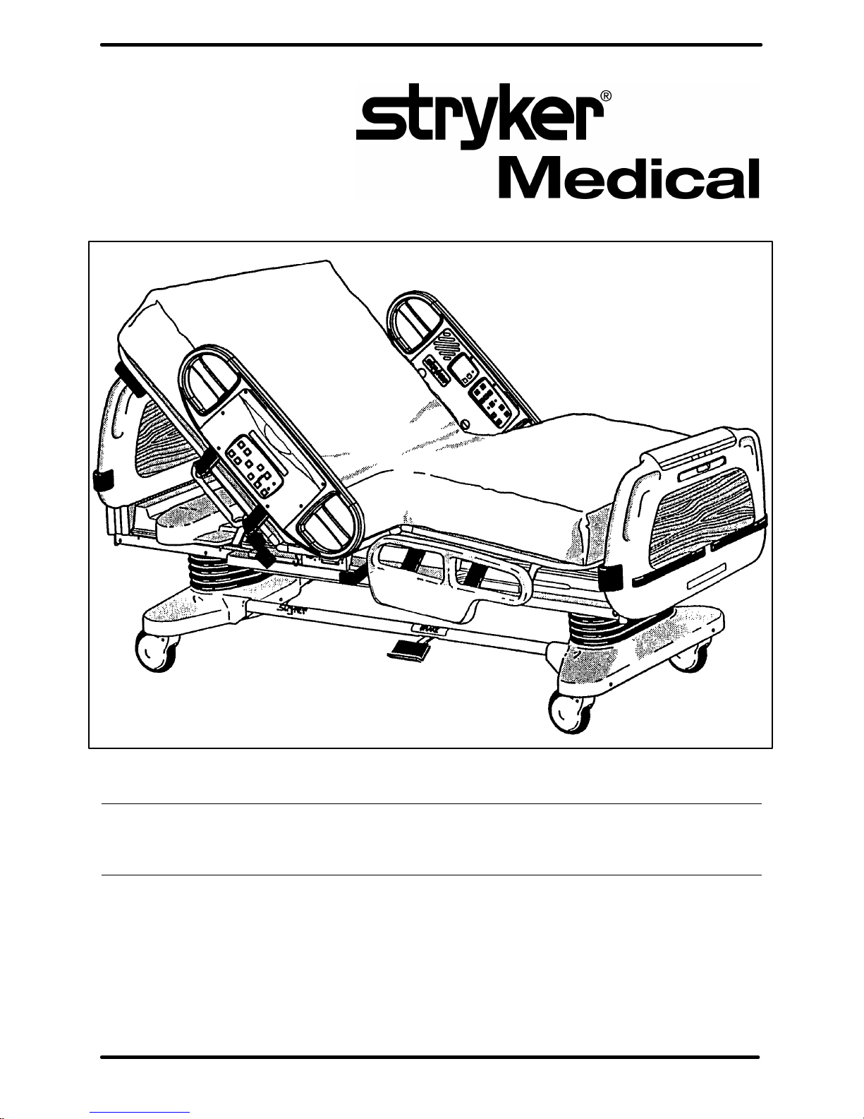
Secure 3000 Bed
OPERATIONS MANUAL
For Parts or Technical Assistance
1–800–327–0770
Page 2

Table of Contents
D INTRODUCTION 2. . . . . . . . . . . . . . . . . . . . . . . . . . . . . . . . . . . . . . . . . . . . . . . . . . . . . . . . . . . . . . . . . . . . . . . . .
D SPECIFICATIONS 2. . . . . . . . . . . . . . . . . . . . . . . . . . . . . . . . . . . . . . . . . . . . . . . . . . . . . . . . . . . . . . . . . . . . . . . .
D WARNING / CAUTION / NOTE DEFINITION 2. . . . . . . . . . . . . . . . . . . . . . . . . . . . . . . . . . . . . . . . . . . . . . . . .
D SAFETY TIPS AND GUIDELINES 3. . . . . . . . . . . . . . . . . . . . . . . . . . . . . . . . . . . . . . . . . . . . . . . . . . . . . . . . . .
D PREVENTATIVE MAINTENANCE 4, 5. . . . . . . . . . . . . . . . . . . . . . . . . . . . . . . . . . . . . . . . . . . . . . . . . . . . . . . .
D SET–UP PROCEDURES 6. . . . . . . . . . . . . . . . . . . . . . . . . . . . . . . . . . . . . . . . . . . . . . . . . . . . . . . . . . . . . . . . . .
D BED ILLUSTRATION 7. . . . . . . . . . . . . . . . . . . . . . . . . . . . . . . . . . . . . . . . . . . . . . . . . . . . . . . . . . . . . . . . . . . . .
D BASE
Brake Pedal Operation 8. . . . . . . . . . . . . . . . . . . . . . . . . . . . . . . . . . . . . . . . . . . . . . . . . . . . . . . . . . . . . . . . . . . .
Steer Pedal Operation 8. . . . . . . . . . . . . . . . . . . . . . . . . . . . . . . . . . . . . . . . . . . . . . . . . . . . . . . . . . . . . . . . . . . . .
D LITTER
CPR Emergency Release Usage 9. . . . . . . . . . . . . . . . . . . . . . . . . . . . . . . . . . . . . . . . . . . . . . . . . . . . . . . . . . .
Foley Bag Hooks Usage, Standard And Isolated (Isolated Optional Equipment) 9. . . . . . . . . . . . . . . . . . .
Foot Prop Usage 9. . . . . . . . . . . . . . . . . . . . . . . . . . . . . . . . . . . . . . . . . . . . . . . . . . . . . . . . . . . . . . . . . . . . . . . . .
Fracture Frame Usage 9. . . . . . . . . . . . . . . . . . . . . . . . . . . . . . . . . . . . . . . . . . . . . . . . . . . . . . . . . . . . . . . . . . . .
I.V. Poles 10. . . . . . . . . . . . . . . . . . . . . . . . . . . . . . . . . . . . . . . . . . . . . . . . . . . . . . . . . . . . . . . . . . . . . . . . . . . . . . .
Night Light Usage (Optional Equipment) 11. . . . . . . . . . . . . . . . . . . . . . . . . . . . . . . . . . . . . . . . . . . . . . . . . . . .
Patient Restraint Strap Locations 11. . . . . . . . . . . . . . . . . . . . . . . . . . . . . . . . . . . . . . . . . . . . . . . . . . . . . . . . . .
D HEAD BOARD/FOOT BOARD
Chart Rack Usage (Optional Equipment) 12. . . . . . . . . . . . . . . . . . . . . . . . . . . . . . . . . . . . . . . . . . . . . . . . . . . .
CPR Board Usage (Optional Equipment) 12. . . . . . . . . . . . . . . . . . . . . . . . . . . . . . . . . . . . . . . . . . . . . . . . . . . .
D SIDERAILS
Positioning Siderails 13. . . . . . . . . . . . . . . . . . . . . . . . . . . . . . . . . . . . . . . . . . . . . . . . . . . . . . . . . . . . . . . . . . . . .
Control Panel Lights 13. . . . . . . . . . . . . . . . . . . . . . . . . . . . . . . . . . . . . . . . . . . . . . . . . . . . . . . . . . . . . . . . . . . . .
Inside Siderail Function Guide 14. . . . . . . . . . . . . . . . . . . . . . . . . . . . . . . . . . . . . . . . . . . . . . . . . . . . . . . . . . . . .
Outside Siderail Function Guide 15, 16. . . . . . . . . . . . . . . . . . . . . . . . . . . . . . . . . . . . . . . . . . . . . . . . . . . . . . . .
DYNAMIC MATTRESS SYSTEM Usage (Optional Equipment) 16. . . . . . . . . . . . . . . . . . . . . . . . . . . . . . . .
D FOOT BOARD
Control Panel Guide, Foot Board 17–18. . . . . . . . . . . . . . . . . . . . . . . . . . . . . . . . . . . . . . . . . . . . . . . . . . . . . . .
Function Lockout System Usage 17. . . . . . . . . . . . . . . . . . . . . . . . . . . . . . . . . . . . . . . . . . . . . . . . . . . . . . . . . . .
LED Display Panel Guide, Foot Board 18. . . . . . . . . . . . . . . . . . . . . . . . . . . . . . . . . . . . . . . . . . . . . . . . . . . . . .
BED EXIT SYSTEM Usage (Optional Equipment) 19. . . . . . . . . . . . . . . . . . . . . . . . . . . . . . . . . . . . . . . . . . . .
Weigh System Control Panel Guide (Optional Equipment) 20, 21. . . . . . . . . . . . . . . . . . . . . . . . . . . . . . . . . .
Weigh System Usage (Optional Equipment) 22, 23. . . . . . . . . . . . . . . . . . . . . . . . . . . . . . . . . . . . . . . . . . . . . .
D PENDANT OPERATION 24. . . . . . . . . . . . . . . . . . . . . . . . . . . . . . . . . . . . . . . . . . . . . . . . . . . . . . . . . . . . . . . . .
D LIMITED WARRANTY
Obtaining Parts and Service 25. . . . . . . . . . . . . . . . . . . . . . . . . . . . . . . . . . . . . . . . . . . . . . . . . . . . . . . . . . . . . . .
Extended Warranty Coverage 25. . . . . . . . . . . . . . . . . . . . . . . . . . . . . . . . . . . . . . . . . . . . . . . . . . . . . . . . . . . . .
Return Authorization 26. . . . . . . . . . . . . . . . . . . . . . . . . . . . . . . . . . . . . . . . . . . . . . . . . . . . . . . . . . . . . . . . . . . . .
Freight Damage Claims 26. . . . . . . . . . . . . . . . . . . . . . . . . . . . . . . . . . . . . . . . . . . . . . . . . . . . . . . . . . . . . . . . . .
Service Contract Coverage 26. . . . . . . . . . . . . . . . . . . . . . . . . . . . . . . . . . . . . . . . . . . . . . . . . . . . . . . . . . . . . . .
Page 3

Introduction
INTRODUCTION
This manual is designed to assist you with the operation of the Secure 3000 Bed. Read it thoroughly before
using the equipment.
SPECIFICATIONS
Maximum Weight Capacity 500 pounds (227 kilograms)
Overall Bed Length/Width 93” x 42–1/2” (with siderails up) – 36” (with siderails down)
238 cm. x 109 cm. (with siderails up) – 92 cm. (with siderails down)
Patient Sleep Surface 84” x 35” – 215 cm. x 90 cm.
Bed Height (to top of seat litter) 16” (Low) x 29–1/2” (High) – 41 cm. (Low) x 76 cm. (High)
Knee Gatch Angle 0_ to 40_
Fowler Angle 0_ to 60_
Trendelenburg/Reverse Trendelenburg –11_ to +11_
Weigh System Accuracy (optional
equipment)
Electrical Requirements – all electrical
requirements meet UL 544 specifications.
1% of total patient weight while the bed is level and up to a 4_
or –4_ angle
3% of total patient weight from 5_ to 11_ angle or –5_ to –11_
angle
115 VAC, 60 Hz, 7.0 Amp. w/o outlet
115 VAC, 60 Hz, 12.0 Amp. w/outlet
230 VAC, 50/60 Hz, 4.0 Amp.
WARNING / CAUTION / NOTE DEFINITION
The words WARNING, CAUTION and NOTE carry special meanings and should be carefully reviewed.
WARNING
The personal safety of the patient or user may be involved. Disregarding this information could result in injury
to the patient or user.
CAUTION
These instructions point out special procedures or precautions that must be followed to avoid damaging the
equipment.
NOTE
This provides special information to make important instructions clearer.
WARNING
Always apply the caster brakes when a patient is getting on or off the bed. Push on the bed to ensure the
brakes are securely locked. Always engage the brakes unless the bed is being moved. Injury could result
if the bed moves while a patient is getting on or off the bed.
2
Page 4

Introduction
SAFETY TIPS AND GUIDELINES
Before operating the Secure Bed, it is important to read and understand all information in this manual. Carefully read and strictly follow the safety guidelines listed on this page.
It is important that all users have been trained and educated on the inherent hazards associated with the
usage of electric beds.
WARNING
S The Secure 3000 Bed is not intended for use with patients less than two years of age.
S Powered bed mechanisms can cause serious injury. Operate bed only when all persons are clear of the
mechanisms.
S To help reduce the number and severity of falls by patients, always leave the bed in the lowest position
when the patient is unattended.
S Leave the siderails fully up and locked when the patient is unattended. When raising the siderails, listen
for the ”click” that indicates the siderail has locked in the up position. Pull firmly on the siderail to ensure
it is locked into position.
Siderails are not intended to be a patient restraint device. It is the responsibility of the attending medical
personnel to determine the degree of restraint necessary to ensure a patient will remain safely in bed.
S Always keep the caster brakes applied when a patient is on the bed (except during transport). Serious
injury could result if the bed moves while a patient is getting in or out of bed. After the brake pedal is
applied, push on the bed to ensure the brakes are locked. When moving the bed, toggle the steer pedal
to put the bed in the steer mode. This locks the swivel motion of the right foot end caster and makes the
bed easier to move.
S Do not attempt to move the foot end of the bed laterally when the steer pedal is activated. When the steer
pedal is activated, the steer caster at the foot end of the bed cannot swivel. Attempting to move the bed
laterally when the steer pedal is activated may cause injury to the user.
S When large spills occur in the area of the circuit boards, 110 volt cables and motors, immediately unplug
the bed power cord from the wall socket. Remove the patient from the bed and clean up the fluid. Have
maintenance completely check the bed. Fluids can affect the operational capabilities of any electrical
product. DO NOT put the bed back into service until it is completely dry and has been thoroughly tested
for safe operation.
S Do not steam clean or hose off the bed. Do not immerse any part of the bed. The internal electric parts
may be damaged by exposure to water. Hand wash all surfaces of the bed with warm water and mild
detergent. Dry thoroughly. Quaternary Germicidal Disinfectants, used as directed, and/or Chlorine
Bleach products, typically 5.25% Sodium Hypochlorite in dilutions ranging between 1 part bleach to 100
parts water, and 2 parts bleach to 100 parts water are not considered mild detergents. THESE PROD-
UCTS ARE CORROSIVE IN NA TURE AND MAY CAUSE DAMAGE TO YOUR BED IF USED IMPROPERLY. If these types of products are used to clean Stryker patient care equipment, measures must be
taken to insure the beds are wiped with clean water and thoroughly dried following cleaning. Failure to
properly rinse and dry the beds will leave a corrosive residue on the surface of the bed, possibly causing
premature corrosion of critical components. Failure to follow the above directions when using these types
of cleaners may void this product’s warranty.
Clean Velcro AFTER EACH USE. Saturate Velcro with disinfectant and allow disinfectant to evaporate.
(Appropriate disinfectant for nylon Velcro should be determined by the hospital.)
S Preventative maintenance should be performed at a minimum of biannually to ensure all bed features
are functioning properly. Close attention should be given to safety features including, but not limited to:
safety side latching mechanisms, frayed electrical cords and components, all electrical controls return
to off or neutral position when released, caster braking systems, no controls or cabling entangled in bed
mechanisms, leakage current 100 microamps maximum, scale and bed exit systems calibrated properly .
S Always unplug bed during service or cleaning. When working under the bed with the bed in the high posi-
tion, always place blocks under the litter frame and set the brakes to prevent injury in case the Bed Down
switch is accidently pressed.
3
Page 5

Preventative Maintenance
CLEANING
Hand wash all surfaces of the bed with warm water and mild detergent. Dry thoroughly.
CAUTION
Quaternary Germicidal Disinfectants, used as directed, and/or Chlorine Bleach products, typically 5.25% So dium Hypochlorite in dilutions ranging between 1 part bleach to 100 parts water, and 2 parts bleach to 100
parts water are not considered mild detergents. THESE PRODUCTS ARE CORROSIVE IN NATURE AND
MAY CAUSE DAMAGE TO YOUR BED IF USED IMPROPERLY. If these types of products are used to clean
Stryker patient care equipment, measures must be taken to insure the beds are wiped with clean water and
thoroughly dried following cleaning. Failure to properly rinse and dry the beds will leave a corrosive residue
on the surface of the bed, possibly causing premature corrosion of critical components. Failure to follow the
above directions when using these types of cleaners may void this product’s warranty.
CAUTION
Do not steam clean or hose off the Secure 3000 Bed. Do not immerse any part of the bed. Some of the internal
parts of the bed are electric and may be damaged by exposure to water.
Clean Velcro AFTER EACH USE. Saturate Velcro with disinfectant and allow disinfectant to evaporate. (Appropriate disinfectant for nylon Velcro should be determined by the hospital.)
In general, when used in those concentrations recommended by the manufacturer, either phenolic type or
quaternary type disinfectants can be used with Staph–Chek fabrics. Iodophor type disinfectants are not recommended for use on Staph–Chek fabrics because staining may result. The following products have been
tested by the Herculite Laboratory and have been found not to have a harmful effect on Staph–Chek fabrics
WHEN USED IN ACCORDANCE WITH MANUFACTURERS RECOMMENDED DILUTION.*
TRADE NAME
A33 Quaternary Airwick (Professional Products Division) 2 ounces/gallon
A33 (dry) Quaternary Airwick (Professional Products Division) 1/2 ounce/gallon
Beaucoup Phenolic Huntington Laboratories 1 ounce/gallon
Blue Chip Quaternary S.C. Johnson 2 ounces/gallon
Elimstaph Quaternary Walter G. Legge 1 ounce/gallon
Franklin Phenomysan F2500 Phenolic Purex Corporation 1 1/4 ounce/gallon
Franklin Sentinel Quaternary Purex Corporation 2 ounces/gallon
Galahad Phenolic Puritan Churchill Chemical Company 1 ounce/gallon
Hi–Tor Quaternary Huntington Laboratories 1/2 ounce/gallon
LPH Phenolic Vestal Laboratories 1/2 ounce/gallon
Matar Phenolic Huntington Laboratories 1/2 ounce/gallon
Omega Quaternary Airwick (Professional Products Division) 1/2 ounce/gallon
Quanto Quaternary Huntington Laboratories 1 ounce/gallon
Sanikleen Quaternary West Chemical Products 2 ounces/ gallon
Sanimaster II Quaternary Service Master 1 ounce/gallon
Vesphene Phenolic Vestal Laboratories 1 1/4 ounce/ gallon
DISINFECTANT
TYPE
MANUFACTURER
*MANUFACTURER’S
RECOMMENDED
DILUTION
REMOVAL OF IODINE COMPOUNDS
This solution may be used to remove iodine stains from mattress cover and foam surfaces.
Use a solution of 1–2 tablespoons Sodium Thiosulfate in a pint of warm water to clean the stained area. Clean
as soon as possible after staining occurs. If stains are not immediately removed, allow solution to soak or
stand on the surface.
4
Page 6

Preventative Maintenance
CHECKLIST
All fasteners secure (reference all assembly prints)
Engage brake pedal and push on the bed to ensure all casters lock securely
”Brake Not Set” LED (on foot board) blinks when brakes are not engaged
Locking steer caster engages and disengages properly
Siderails move, latch and stow properly
CPR release working properly
Foot prop intact and working properly
I.V. pole working properly
Foley bag hooks intact
Optional chart rack intact and working properly
Optional CPR board not cracked or damaged and stores properly
No cracks or splits in head and foot boards
No rips or cracks in mattress cover
All functions on head end siderails working properly (including LED’s)
All functions on footboard working properly (including LED’s)
Scale and Bed Exit system calibrated properly
Motion Interrupt switches working properly
Optional night light working properly
Power cord not frayed
No cables worn or pinched
All electrical connections tight
All grounds secure to the frame
Ground impedance not more than 100 milliohms
Current leakage not more than 100 microamps
Apply grease to litter grease points
Bed Serial No.
Completed By:_________________________________ Date:_____________
5
Page 7

Set–Up Procedures
SET–UP PROCEDURES
It is important that the Secure 3000 Bed is working properly before it is put into service. The following list
will help ensure that each part of the bed is tested.
S Plug the bed into a properly grounded, hospital grade wall receptacle and ensure the ”Power” LED light
at the foot end of the bed comes on.
WARNING
The 3000 is equipped with a hospital grade plug for protection against shock hazard. It must be plugged directly into a properly grounded three–prong receptacle. Grounding reliability can be achieved only when a
hospital grade receptacle is used.
S Plug the optional interface cable into the 37 pin connector under the litter frame at the head end of the
bed, and into the ”Patient Station”, ”Head Wall”, ”Docker Station”, or equivalent (whichever applies). Test
the interface cable to verify it is functioning properly.
WARNING
Use only a Stryker supplied interface cable. Use of any other cable may cause the bed to function improperly
which may result in patient or user injury.
S Ensure the siderails raise, lower and store smoothly and lock in the up and intermediate positions (page
13).
S Ensure that all four casters lock when the brake pedal is engaged (page 8).
NOTE
Ensure that the ”Brake Not Set” LEDs located on the outside of the head end siderails and on the foot board
control panel come on when the brakes are disengaged.
S Run through each function on the foot board control panel to ensure that each function is working properly
(page 17–19).
S Run through each function on both head end siderails to ensure that each is working properly (page
14–16).
S Activate the motion stop system to ensure it is functioning properly: press and hold down the BED DOWN
key. As the bed lowers, lift up on the motion interrupt pan (page 7) and ensure the downward motion
stops. Release the pan and allow the downward motion to continue.
NOTE
The bed’s upward motion or other functions are not disrupted by the motion stop system.
If any problems are found during bed set–up, contact Stryker Customer Service at 800–327–0770.
Damaged Merchandise
ICC Regulations require that claims for damaged merchandise must be made with the carrier within fifteen
(15) days of receipt of merchandise. DO NOT ACCEPT DAMAGED SHIPMENTS UNLESS SUCH DAMAGE
IS NOTED ON THE DELIVERY RECEIPT AT THE TIME OF RECEIPT. Stryker Customer Service must be
notified immediately. Stryker will aid the customer in filing a freight claim with the appropriate carrier for damages incurred. Claim will be limited in amount to the actual replacement cost. In the event that this information
is not received by Stryker within the fifteen (15) day period following the delivery of the merchandise, or the
damage was not noted on the delivery receipt at the time of receipt, the customer will be responsible for payment of the original invoice in full.
Claims for any short shipment must be made within thirty (30) days of invoice.
6
Page 8
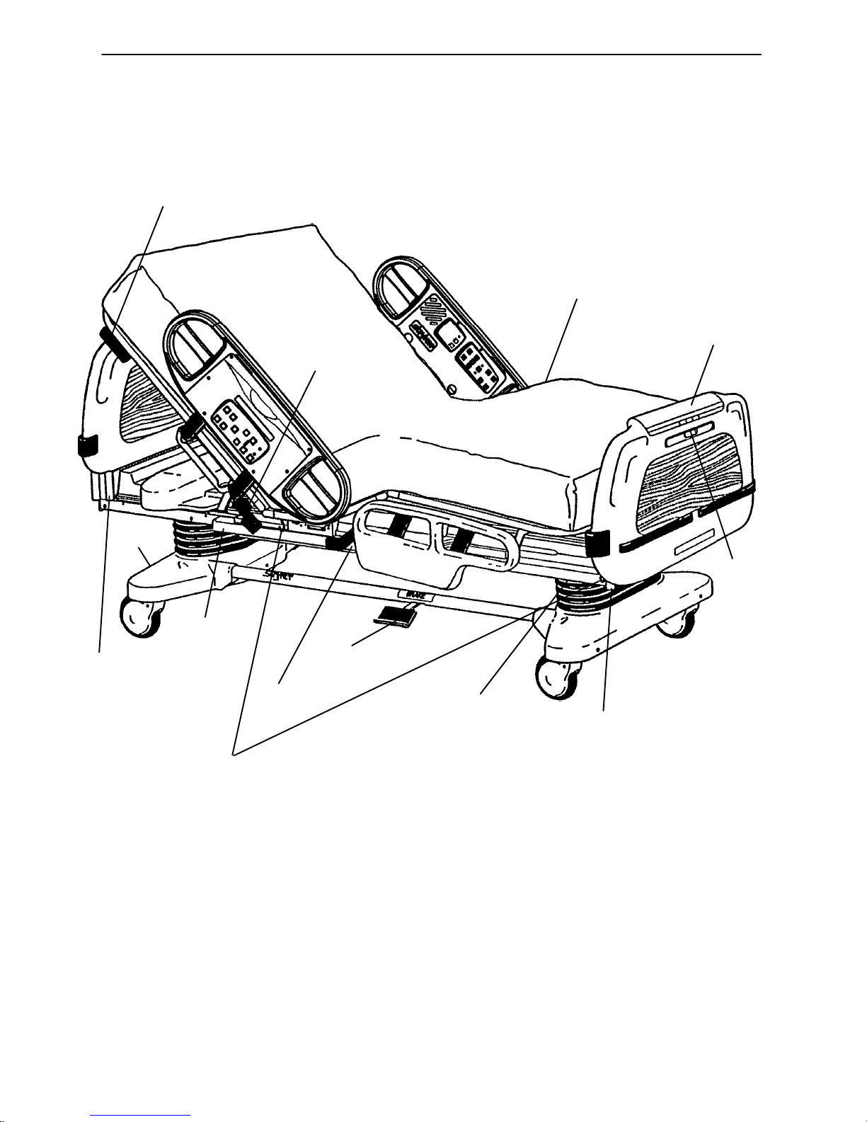
PATIENT’S
RIGHT
CPR Release
Handle
HEAD END
Siderail Release
Handle
Bed Illustration
PATIENT’S
LEFT
DMS Port Connector
(Under Seat Section)
Footboard
Control
Panel
Steer
Pedal
I.V. and
Fracture Frame
Mount
Motion
Interrupt
Pan
Foley Bag Hooks
(Standard)
Night
Light
Brake Pedal
Foley Bag Hook
(Isolated)
(Optional Equip.)
I.V. and
Fracture Frame
Mount
Chart
Rack
(Optional Equip.)
FOOT END
7
Page 9

Base Operation Guide
BRAKE PEDAL OPERATION
WARNING
Always apply the caster brakes when a patient is getting on or off the bed. Push on the bed to ensure the
brakes are securely locked. Always engage the brakes unless the bed is being moved. Injury could result
if the bed moves while a patient is getting on or off the bed.
To activate the brakes, push down once on the pedal
identified by the label at right (located at the midpoint of
the bed on both sides). To disengage, push down once.
NOTE
There are LED lights on the outside of the head end siderails and on the foot end control panel that will blink
when the brakes are not engaged only if the bed is plugged into a wall socket (see pages 16 & 17). The brakes
will still operate properly when the bed is not plugged in.
STEER PEDAL OPERATION
The purpose of the steer caster is to help guide the bed along a straight line and to help with pivoting at corners
when the bed is moved.
To activate the steer caster, move the pedal located
at the head end of the bed to your left as shown on
the label.
NOTE
For proper ”tracking” of the steer caster, push the bed approximately 10 feet to allow the wheels to face the
direction of travel before engaging the steer pedal. If this is not done, proper ”tracking” will not occur and the
bed will be difficult to steer.
WARNING
Do not attempt to move the foot end of the bed laterally when the steer pedal is activated. When the steer
pedal is activated, the steer caster at the foot end of the bed cannot swivel. Attempting to move the bed laterally when the steer pedal is activated may cause injury to the user.
8
Page 10

Litter Operation Guide
CPR EMERGENCY RELEASE USAGE
When quick access to the patient is needed, and the Fowler is raised, squeeze one of the two red release
handles (see illustration, page 7) and the Fowler can be guided down to a flat position.
NOTE
The handle can be released at any time to stop the Fowler from lowering.
FOLEY BAG HOOKS USAGE, STANDARD AND ISOLATED (Isolated Optional Equipment)
The standard Foley bag hooks are found at two locations on both sides of the bed, under the frame rail below
the seat section and at the extreme foot end of the bed.
NOTE
The patient weight reading on the bed scale system will be affected by using the standard Foley bag hooks.
The optional isolated Foley bag hooks are located under the litter frame at the top of the foot end bellows.
CAUTION
The Foley bag hooks move when the Fowler is raised or lowered. Fowler motion must be locked out when
using these hooks to avoid inadvertent movement of the hooks.
NOTE
The patient weight reading on the bed scale system will not be affected by usage of the isolated Foley bag
hooks.
FOOT PROP USAGE
To prop the foot end of the Knee Gatch up, grasp
the handle (A) at the end of the Knee Gatch and
lift upward, allowing the latch arm to engage at the
desired height. To release the prop, (B) lift up on
the handle (A) and swing the foot prop (B) toward
the head end of the bed to disengage the hinge
and allow the foot end to lower.
WARNING
The intent of the foot prop is to elevate a patient’s
feet. To avoid injury while cleaning or servicing under
the foot section, secure the foot section with string
or bungee cords or hold it up out of the way.
B
A
FOOT END
FRACTURE FRAME USAGE
A standard fracture frame can be mounted on the bed using the I.V. sockets located on all four corners of
the bed. I.V. poles can be used in conjunction with a fracture frame if I. V. pole adaptor sockets are purchased.
WARNING
Use only retractable traction or fracture frames. Failure to use a retractable frame may result in injury to the
patient and/or damage to the equipment.
9
Page 11
Litter Operation Guide
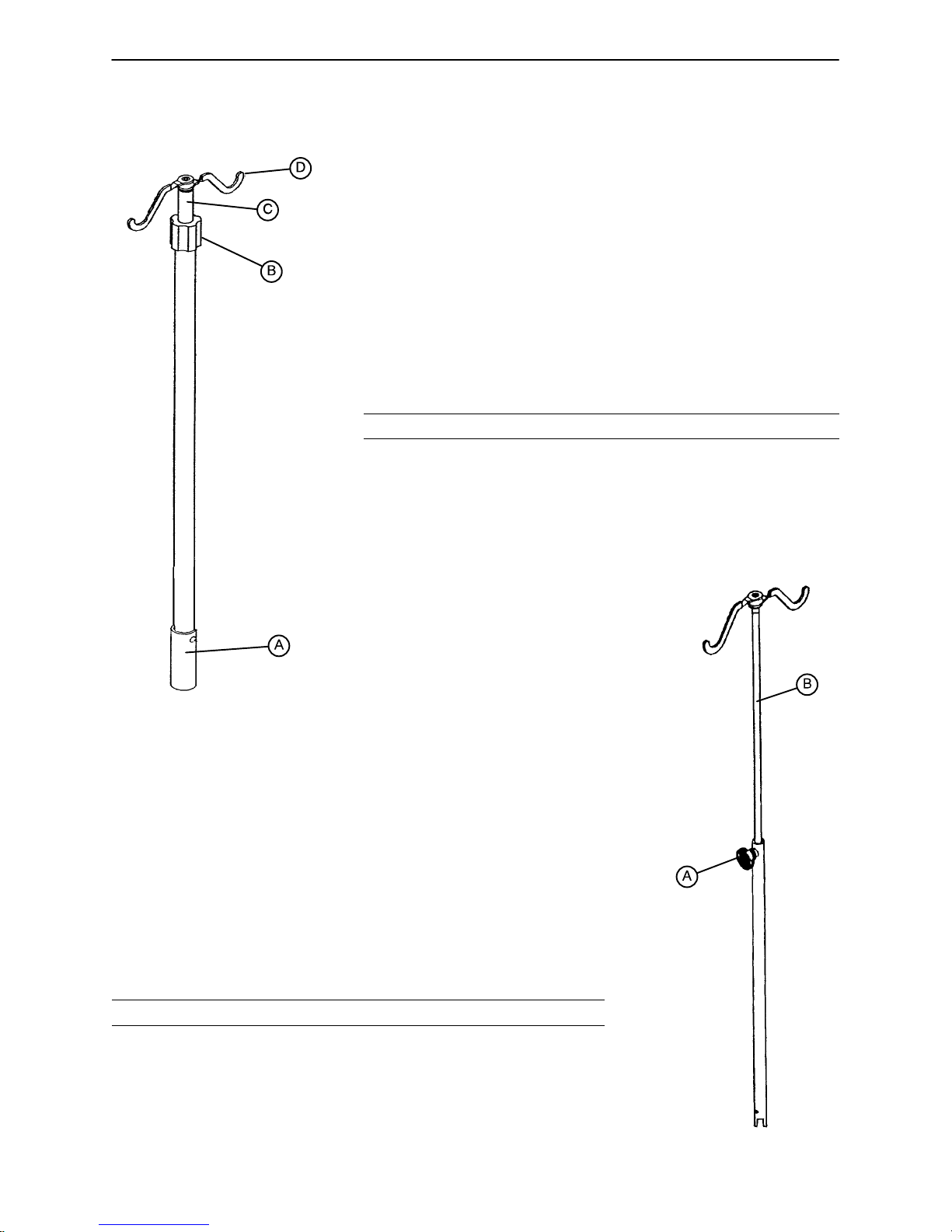
I.V. POLES
To use the Permanently Attached I.V. pole (optional equipment):
1. Lift and pivot the pole from the storage position and push down
until it is locked into receptacle (A).
2. To raise the height of the pole, turn the lock actuator (B) counter–
clockwise and pull up on the telescoping portion (C) of the pole to
raise it to the desired height.
3. Turn the lock actuator (B) clockwise to lock the telescoping portion
in place.
4. Rotate the I.V. hangers (D) to desired position and hang I.V. bags.
CAUTION
The weight of the I.V. bags should not exceed 40 pounds.
To use the ”Removable” I.V. pole (optional equipment):
1. Remove the pole from its storage position located at the foot end of the
bed, under the foot board, or at the left side of the bed below the litter.
2. Install the pole at any of the six receptacles on the bed top (located on
all four corners of the bed and at the midpoint of the bed, on both sides.)
3. To raise the height of the pole, turn knob (A) counterclockwise and pull
up on the telescoping portion (B) of the pole and raise it to the desired
height.
4. Turn knob (A) clockwise to tighten the telescoping portion in place.
CAUTION
The weight of the I.V. bags should not exceed 40 pounds.
10
Page 12

Litter Operation Guide
NIGHT LIGHT USAGE (Optional Equipment)
The bed may be equipped with two optional night
lights (A) to illuminate the floor area around the
bed.
There is a master switch at the foot end of the bed
on the right side that turns both lights on and off.
Each light also has a switch to control the individual light.
NOTE
If the switch is turned off on either of the individual
lights, the master switch will not control that light.
FOOT END
PATIENT RESTRAINT STRAP LOCATIONS
The bed is equipped with 12 separate locations for installing patient restraint straps. The ”cutouts” in the bed
top are located directly across from each other (on both sides of the bed).
WARNING
Improperly adjusted restraint straps can cause serious injury to a patient. The clinician must use her/his
judgement to determine proper use of restraint straps and restraint strap locations.
Clean Velcro AFTER EACH USE. Saturate Velcro with disinfectant and allow disinfectant to evaporate. (Appropriate disinfectant for nylon Velcro should be determined by the hospital.)
NURSE CALL BACK–UP BATTERY
To prevent a low battery condition when the bed is not plugged in, position the cord out switch at the head
end of the bed to the off position. The switch is identified by the label shown below. If the switch is not positioned as shown below and the bed power cord and pendant cord are unplugged, the life of the back–up battery will be significantly reduced.
If the power light (located on the foot board) is flashing, the Nurse Call battery needs to be replaced. The
battery is located on the patient’s left side at the head end of the bed. No tools are required to replace the
battery. Unplug the bed power cord from the wall socket and replace the battery.
11
Page 13

Head Board/Foot Board Operation Guide
CHART RACK USAGE (Optional Equipment)
If the bed is equipped with the optional chart
rack, it is located on the foot board. To use,
pull handle rod (A) downward. To store,
push the handle back to its storage position
until it locks in place.
CAUTION
Do not use handle rod (A) as a device for
pulling the bed. Doing so may cause
damage to the chart rack and foot
board.
The weight of items placed on the chart
rack should not exceed 5 pounds or damage to the chart rack and foot board could
occur.
A
FOOT END
CPR BOARD USAGE (Optional Equipment)
If the bed is equipped with the optional CPR board, it is stored on the bed’s head board. To remove, pull
away from the head board and lift out of storage position. If the CPR board option was not purchased,
the head board can also be removed and used as an emergency CPR board.
12
Page 14

Siderail Operation Guide
POSITIONING SIDERAILS
NOTE
The siderails can be locked at two heights (intermediate & full).
The siderails can be tucked away under the bed when not in use. T o remove the rail from the tucked position,
grasp the top of the rail and pull outward.
To engage the head end siderail, grasp the rail and swing it upward toward the head end of the bed until it
rests in the ”intermediate” position. To continue to full height, push in the blue release handle (A) and rotate
the siderail until full height is reached.
To engage the foot end siderail, the same procedure is required as for the head
end siderail, however, the siderail swings to the foot end of the bed.
WARNING
Be sure rail is locked securely
into position. Siderails are not
intended to keep patients from
exiting the bed. They are
designed to keep a patient
from inadvertently rolling off
the bed. Proper restraint
methods should be utilized to
ensure the patient remains in bed.
The siderails are not intended to be
used as a push device.
A
To disengage the rail, push in the blue release handle (A) and swing rail down to desired height. Tuck away
siderails by pushing the rails under the bed. Rails must be in the full down position before they can be tucked.
SIDERAIL CONTROL PANEL LIGHTS
The bed is equipped with lights to illuminate the head end siderail control panel and the red nurse call
switches. Both can be activated at the foot board control panel. Three settings are available for the control
panel lights: low, medium and high intensity. When all lights are off, push the siderail control light button at
the foot board once to turn on both the control lights and the nurse call light at the siderail. Push again to
change from low to medium setting, and a third time to change to the high setting. The nurse call light intensity
is not affected. Pushing the button a fourth time will turn off the siderail control panel lights and pushing it
a fifth time will turn off the red nurse call light as well (see control panel guide page 17).
CAUTION
The intent of the red nurse call light on the siderails is to ensure the patient has immediate understanding of
where to push to contact the nurse station. Turning this light off will compromise this ability, especially in a
darkened room.
13
Page 15

Siderail Operation Guide
INSIDE SIDERAIL FUNCTION GUIDE
(Patient’s Right Rail)
1. Push to raise Knee Gatch.
2. Push to lower Knee Gatch.
3. Push to raise Fowler.
4. Push to lower Fowler.
(Patient’s Left Rail)
1. Push to raise Fowler.
2. Push to lower Fowler.
3. Push to raise Knee Gatch.
4. Push to lower Knee Gatch.
1. Push to activate Nurse Call.
NOTE
Yellow LED will light when button is pushed. Red LED will light with
Nurse Station acknowledgment.
" This panel is optional equipment.
1. Push to turn TV or radio on and to select a channel.
2. Push to increase volume.
3. Push to decrease volume.
" This panel is optional equipment.
1. Push to increase firmness of mattress
2. Push to decrease firmness of mattress.
(See page 16 for system instructions).
" This panel is optional equipment.
1. Push to turn the room light on.
2. Push to turn the bed overhead light on.
" This panel is optional equipment.
14
Page 16
Siderail Operation Guide
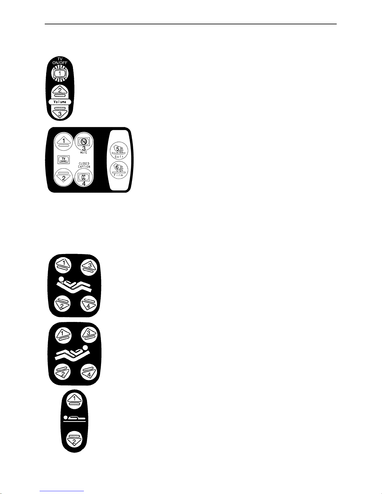
INSIDE SIDERAIL FUNCTION GUIDE (CONTINUED)
1. Push to turn TV on or off.
2. Push to raise the TV volume.
3. Push to lower the TV volume.
1. Push to change the TV channel up.
2. Push to change the TV channel down.
3. Push to mute TV volume. Push again to turn the sound back on.
4. Push to display closed captioning. Push again to turn off closed captioning.
5. Press to decrease the firmness of the mattress.
6. Press to increase the firmness of the mattress.
" These panels are optional equipment.
OUTSIDE SIDERAIL FUNCTION GUIDE
(Patient’s Right Rail)
1. Push to raise Fowler.
2. Push to lower Fowler.
3. Push to raise Knee Gatch.
4. Push to lower Knee Gatch.
" This panel is optional equipment.
(Patient’s Left Rail)
1. Push to raise Knee Gatch.
2. Push to lower Knee Gatch.
3. Push to raise Fowler.
4. Push to lower Fowler.
" This panel is optional equipment.
1. Push to raise bed height.
2. Push to lower bed height.
15
Page 17
Siderail Operation Guide
OUTSIDE SIDERAIL FUNCTION GUIDE (CONTINUED)
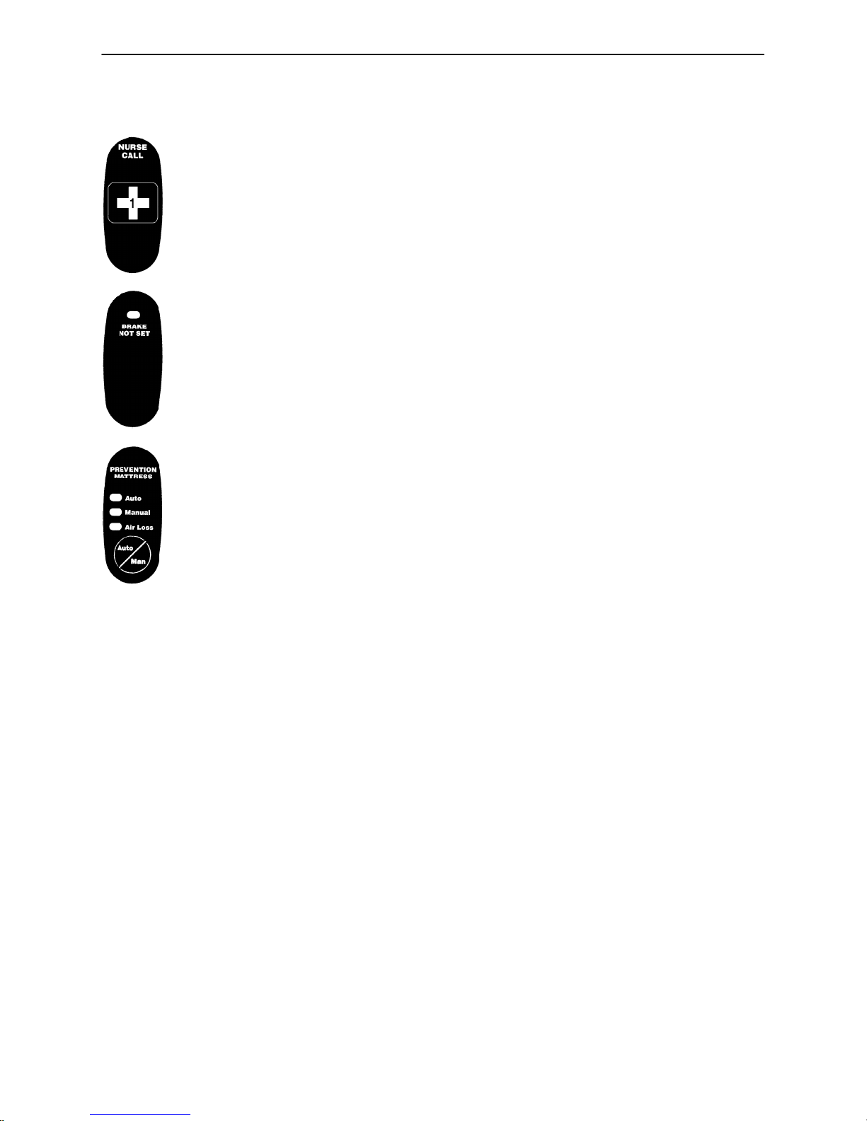
Push to activate Nurse Call.
" This panel is optional equipment.
LED will blink when the brakes are not set.
Push to activate auto or manual mode of the Dynamic Mattress System.
LED will light to indicate selected mode and/or possible air leak.
" This panel is optional equipment.
DYNAMIC MATTRESS SYSTEM USAGE (OPTIONAL EQUIPMENT)
1. The system can be set in either ”AUTOMATIC” or ”MANUAL” modes. The ”AUTO/MAN” switch is used
to activate both modes. When Automatic mode is selected, the ”AUTOMATIC” LED on the siderail control
panel will be on. When Manual mode is selected, the ”MANUAL” LED on the siderail control panel will
be on. The “AUTO/MAN” switches are located on the control panels on the outside of the head end siderails (see above).
2. When the Automatic mode is selected, the firmness of the mattress will adjust automatically as needed.
When the Manual mode is selected, the firmness of the mattress can be adjusted by the patient or the
hospital clinical staff. The ”FIRM” and ”SOFT” switches are located on the control panels on the inside
of the head end siderails (see page 14).
NOTE
The mattress power cord must be plugged into the bed for the mattress to operate. See page 7 for ”DMS
Port” location.
16
Page 18
Foot Board Operation Guide
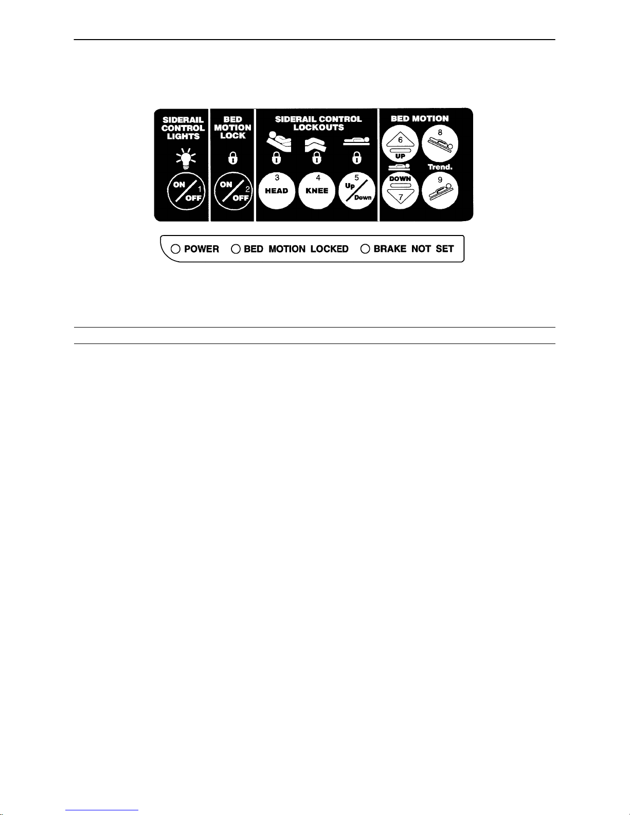
FOOT BOARD CONTROL PANEL GUIDE
1. Push repeatedly for low, medium and high settings for siderail control lights. Pushing a fourth and fifth time
will turn off the siderail control lights and the red nurse call light respectively (see page 13).
CAUTION
The intent of the red nurse call light on the siderails is to ensure the patient has immediate understanding of
which button to push to contact the nurse station. T urning the red light off may compromise this ability, especially in a darkened room.
2. Push to lock out all bed motions. The MOTION lock icon and the “BED MOTION LOCKED” LED will light.
Push again to unlock.
3. Push to lock out Back Rest controls at both siderails. The HEAD lock icon will light. Push again to unlock.
4. Push to lock out Knee Gatch controls at both siderails. The KNEE lock icon will light. Push again to unlock.
5. Push to lock out bed height movement at both siderails. The UP/DOWN lock icon will light. Push again
to unlock.
6. Push to raise bed height.
7. Push to lower bed height.
8. Push to lower head end/raise foot end of bed (Trendelenburg position).
9. Push to lower foot end/raise head end of bed (Reverse Trendelenburg position).
FUNCTION LOCKOUT SYSTEM USAGE
1. To lock out the bed movement functions on the siderails and prevent the patient from changing the positioning of the bed, push the ”HEAD”, ”KNEE” and/or ”UP/DOWN” switches in the ”Siderail Control Lockouts”
module on the foot board control panel.
NOTE
The foot board controls for these motions are not affected by the lockout switches.
The ”padlock” symbol on the control panel will be lighted when that function is locked out.
2. To lock out the entire bed motion for all switches on the bed (siderails and foot board), push the ”ON/OFF”
switch in the ”Bed Motion Lock” module on the foot board control panel.
17
Page 19
Foot Board Operation Guide
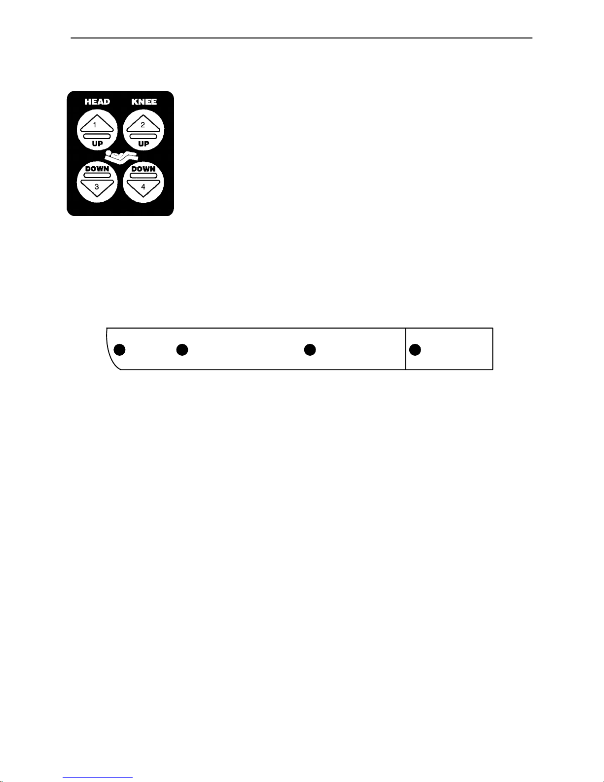
FOOT BOARD CONTROL PANEL GUIDE (CONTINUED)
1. Push to raise Fowler.
2. Push to raise Knee Gatch.
3. Push to lower Fowler.
4. Push to lower Knee Gatch.
" This panel is optional equipment.
LED DISPLAY PANEL GUIDE
The LED Display Panel is located at the foot end of the bed, under the Control Panel.
POWER BED MOTION LOCKED BRAKE NOT SET BED EXIT ON
”POWER” – will light when the bed is plugged into the wall receptacle. Will blink if the 9V Nurse Call battery
needs to be replaced.
”BED MOTION LOCKED” – will light when the Bed Motion Lock has been activated.
”BRAKE NOT SET” – will blink when the brakes have not been set.
”BED EXIT ON” – will light when the Bed Exit function has been activated (optional equipment).
18
Page 20
Foot Board Operation Guide
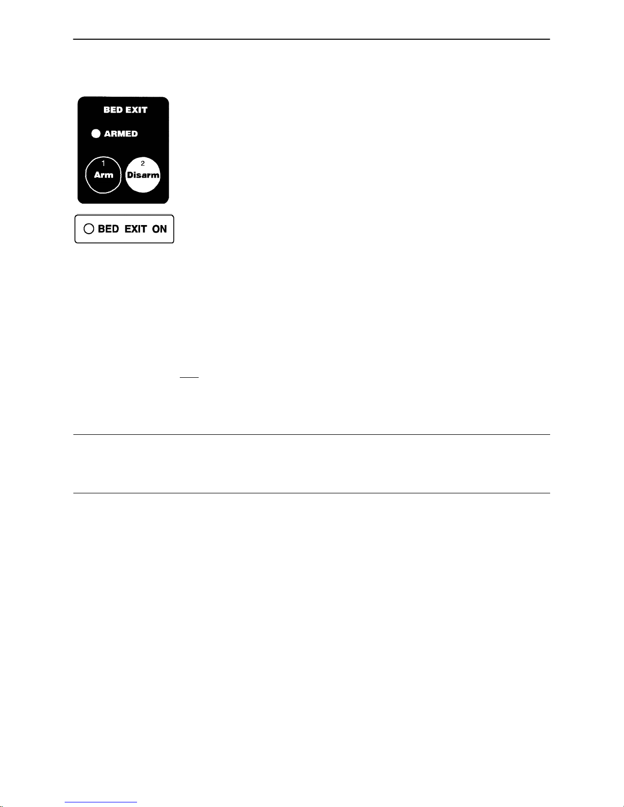
CENTER OF GRAVITY BED EXIT (OPTIONAL EQUIPMENT)
1. Push to activate Bed Exit function.
2. Push to deactivate Bed Exit function.
NOTE
If the scale system is in use, it will switch to ”of f” when Bed Exit is armed. Bed Exit will be temporarily disarmed
when the scale system is activated and will re–arm when the scale system shuts off. When the bed is
equipped with scales, the scales must be properly zeroed for the Bed Exit System to function properly (see
page 22 for scale system usage instructions). If bed is not equipped with a scale system, follow the procedure
below.
1. Before putting a new patient on the bed: prepare bed for patient stay by adding linens and equipment to
the bed. Press and hold ”ARM” and ”DISARM” keys together for 5 seconds – ”ARMED” light will begin
to flash. Release ”ARM” and ”DISARM” keys and do not touch the bed until ”ARMED” light stops flashing.
2. Once the new patient is on the bed: push ”ARM” key and release (”ARMED” light will come on).
3. To deactivate Bed Exit, push ”DISARM”. The ”ARMED” and ”BED EXIT ON” LED’s will turn off.
WARNING
The Bed Exit System is intended only to aid in the detection of a patient exiting the bed. It is NOT intended
to replace patient monitoring protocol. It signals when a patient is about to exit. Adding or subtracting objects
from the bed after arming the bed exit system may cause a reduction in the sensitivity of the bed exit system.
19
Page 21
Foot Board Operation Guide
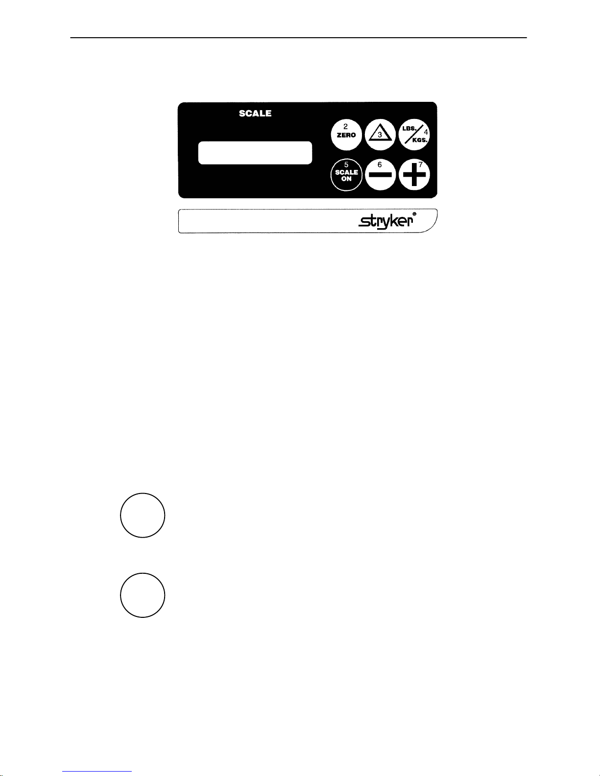
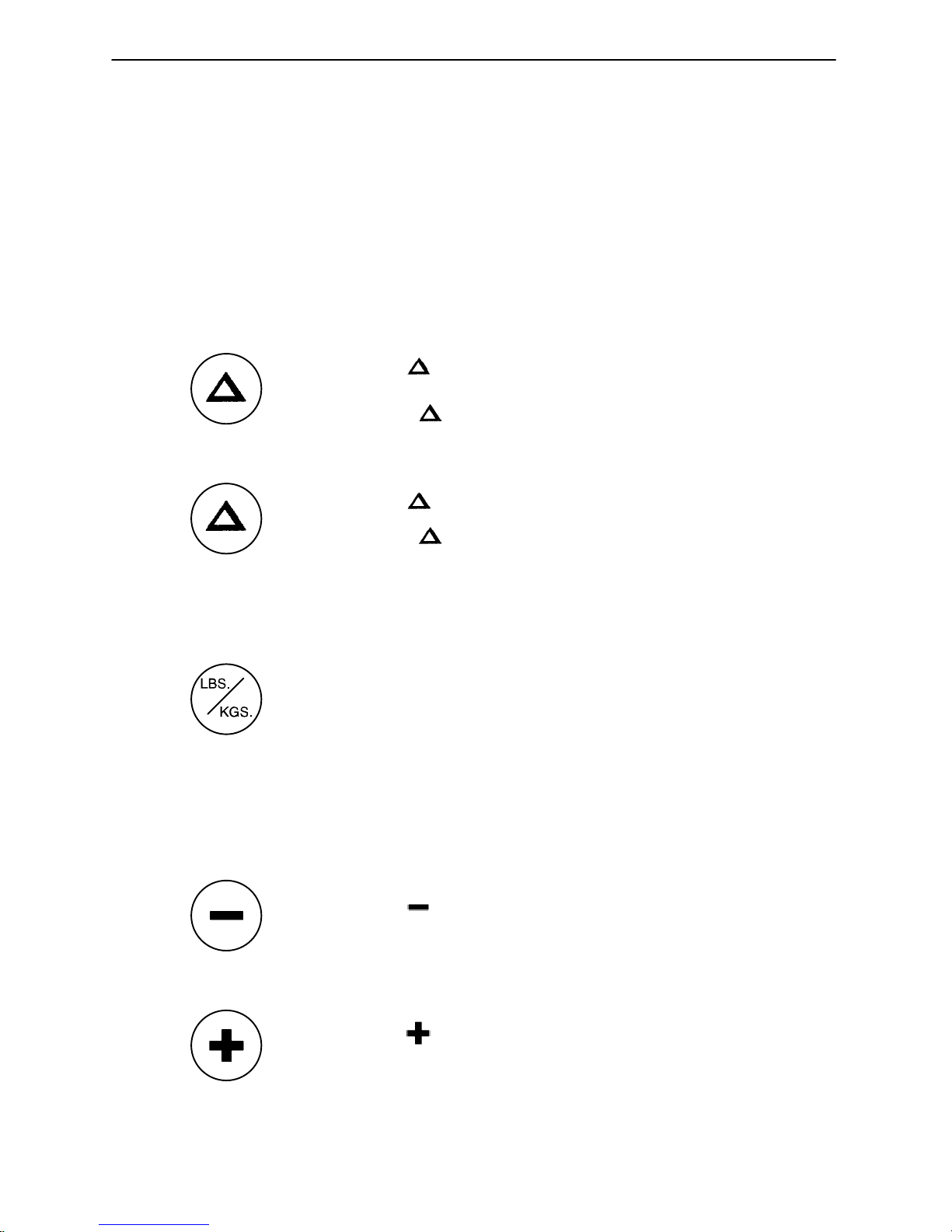
WEIGH SYSTEM CONTROL PANEL GUIDE
1
1. LCD – displays patient weight.
2. Push to zero bed.
3. Push when changing equipment on the bed.
4. Push to change weight from pounds to kilograms or back.
5. Push to turn weight system on.
6. Push to decrease numerical value of displayed weight.
7. Push to increase numerical value of displayed weight.
NOTE
After approximately 30 seconds of idle time, the scale display will turn off and will show the Trendelenburg
angle of the bed. Press “SCALE ON” to return to the weight display.
SYMBOL ACTION DISPLAY
To prepare bed for new patient:
Release the button after the ”WEIGHING...”
SCALE
ON
ZERO
Press and hold ”SCALE ON”. ”LET GO FOR SCALE”
display reads: ”XXX.X LB”
”LET GO FOR SCALE”
Press and hold ”ZERO””HOLD TO ZERO WT.”
”RELEASE TO ZERO”
Release ”ZERO””DO NOT TOUCH BED”
”0.0 LB”
20
Page 22
Foot Board Operation Guide
WEIGH SYSTEM CONTROL PANEL GUIDE (CONTINUED)
SYMBOL ACTION DISPLAY
To add or remove equipment
during patient stay without
affecting registered patient
weight:
Press and release ”SCALE ON””WEIGHING...”
Press ”HOLD TO START”
Release ”DO NOT TOUCH BED”
Add or remove equipment.
”XXX.X LB”
”RELEASE TO START”
”ADD/REMOVE EQUIP.”
Press ”RELEASE TO FIN.”
Release ”DO NOT TOUCH BED”
To convert the patient’s weight:
To convert the patient’s weight ”WEIGHT NOW KGS”
to kilograms, press and release ”XXX.X KG”
”LBS./KG.”
Repeat the procedure to return to
pounds.
To change the numerical value
of displayed weight:
Press and hold to scroll to ”HOLD TO DEC. WT.”
desired weight. ”XXX.X LB”
”XXX.X LB”
Press and hold to scroll to ”HOLD TO INC. WT.”
desired weight. ”XXX.X LB”
21
Page 23

Weigh System Usage
OPERATING THE SCALE BEFORE PUTTING A NEW PATIENT IN BED
S Prepare bed for patient stay (linens, pillows, etc.).
S Press and hold ”SCALE ON”. Release the button after the display reads ”LET GO FOR SCALE”. (This
will turn off the Trend. angle display and activate the scale). The scale monitor will read:
”LET GO FOR SCALE”
”WEIGHING”
”XXX.X LB”
S Press and hold ”ZERO”. The scale monitor will read:
”HOLD TO ZERO WT.”
”RELEASE TO ZERO”
S Release ”ZERO”. The scale monitor will now read:
”DO NOT TOUCH BED”
”0.0 LB”
The bed is now ready for the patient.
NOTE
Do not zero the bed while a patient is in bed. Inaccurate patient weight reading will result. If this should occur,
remove the patient and zero the bed.
OPERATING THE SCALE IF PATIENT IS ALREADY IN BED
S If it is necessary to add or remove special equipment (monitors, pumps, etc.) during the patient’s
stay, press and release ”SCALE ON” to activate the weigh system. After the scale monitor reads
”XXX.X LB”, press and hold . The scale monitor will read:
”HOLD TO START”
”RELEASE TO START”
S Release . The scale monitor will read:
”DO NOT TOUCH BED”
”ADD/REMOVE EQUIP”
S Add or remove the equipment and press . The scale monitor will read:
”RELEASE TO FIN.”
S Release . The scale monitor will read:
The weight displayed will be that of the patient only.
”DO NOT TOUCH BED”
”XXX.X LB”
22
Page 24

Weigh System Usage
CONVERTING THE PATIENT’S WEIGHT
S To convert the patient’s weight from pounds to kilograms, press and release ”SCALE ON” to activate
the weigh system. After the scale monitor reads ”XXX.X LB”, press and release the ”LBS/KGS” button. The scale monitor will read:
”WEIGHT NOW KGS”
”XXX.X KG”
S Repeat the procedure to return to pounds. The display will read:
”WEIGHT NOW LBS”
”XXX.X LB”
CHANGING THE NUMERICAL VALUE OF DISPLAYED WEIGHT
S To decrease the numerical value of the displayed weight, press and hold ”–”. The scale monitor will
read:
”HOLD TO DEC. WT.”
”XXX.X LB”
S Hold ”–” until desired value is achieved.
S To increase the numerical value of the displayed weight, press and hold ”+”. The scale monitor will
read:
”HOLD TO INC. WT.”
”XXX.X LB”
S Hold ”+” until desired value is achieved.
NOTE
The weigh system will shut off approximately one minute after a function has been used, if another function
is not activated. Display light will shut off and display will read ”SCALE OFF”.
The weigh system will retain all patient weight information in its memory even when the scale monitor is off
or when the bed is unplugged from the wall socket.
23
Page 25
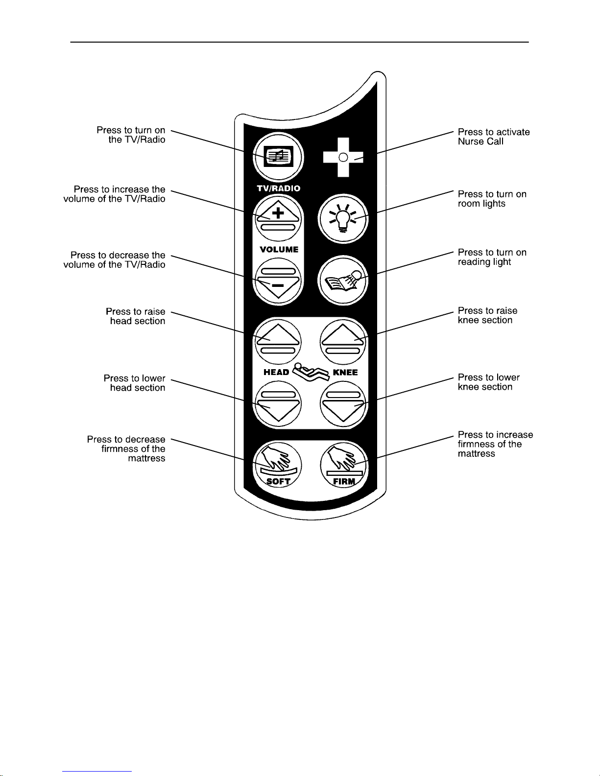
Optional Pendant Operation
24
Page 26

Warranty
Limited Warranty:
Stryker Medical Division, a division of Stryker Corporation, warrants to the original purchaser that its products
should be free from defects in material and workmanship for a period of either: one (1) year parts and labor
or two (2) years for parts only, after date of delivery. Stryker ’s obligation under this warranty is expressly
limited to supplying replacement parts for , or replacing, at its option, any product which is, in the sole discretion
of Stryker, found to be defective. Stryker warrants to the original purchaser that the frame and welds on its
beds will be free from structural defects for as long as the original purchaser owns the bed. If requested by
Stryker, products or parts for which a warranty claim is made shall be returned prepaid to Stryker’s factory.
Any improper use or any alteration or repair by others in such manner as in Stryker’s judgement affects the
product materially and adversely shall void this warranty. N o employee or representative of Stryker is authorized to change this warranty in any way.
This statement constitutes Stryker’s entire warranty with respect to the aforesaid equipment. STRYKER
MAKES NO OTHER WARRANTY OR REPRESENTATION, EITHER EXPRESSED OR IMPLIED, EXCEPT
AS SET FORTH HEREIN. THERE IS NO WARRANTY OF MERCHANTABILITY AND THERE ARE NO
WARRANTIES OF FITNESS FOR ANY PARTICULAR PURPOSE. IN NO EVENT SHALL STRYKER BE
LIABLE HEREUNDER FOR INCIDENTAL OR CONSEQUENTIAL DAMAGES ARISING FROM OR IN ANY
MANNER RELATED TO SALES OR USE OF ANY SUCH EQUIPMENT.
To Obtain Parts and Service:
Stryker products are supported by a nationwide network of dedicated Stryker Field Service Representatives.
These representatives are factory trained, available locally, and carry a substantial spare parts inventory to
minimize repair time. Simply call your local representative, or call Stryker Customer Service at (800)
327–0770.
Extended Warranty Coverage:
Stryker offers warranties to provide an extension of the above stated warranty, that are available upon the
purchase of the Model 3000 Bed.
Covered under these warranties:
S All replacement parts, as set forth in the limited warranty statement above (excluding mat-
tresses and consumable items)
NOTE: mattresses carry a separate warranty plan. Refer to mattress documentation.
S Labor and Travel for all scheduled and unscheduled calls (if labor option is chosen).
The following extended options are available at a nominal charge:
S 3 years parts – no labor (1 year extension to standard 2 year parts warranty).
S 4 years parts – no labor (2 year extension to standard 2 year parts warranty).
S 5 years parts – no labor (3 year extension to standard 2 year parts warranty).
S 2 years parts and labor (1 year extension to standard 1 year parts and labor warranty).
S 3 years parts and labor (2 year extension to standard 1 year parts and labor warranty).
S 4 years parts and labor (3 year extension to standard 1 year parts and labor warranty).
S 5 years parts and labor (4 year extension to standard 1 year parts and labor warranty).
25
Page 27

Warranty
Return Authorization:
Merchandise cannot be returned without approval from the Stryker Customer Service Department. An authorization number will be provided which must be printed on the returned merchandise. Stryker reserves the
right to charge shipping and restocking fees on returned items.
SPECIAL, MODIFIED, OR DISCONTINUED ITEMS NOT SUBJECT TO RETURN.
Damaged Merchandise:
ICC Regulations require that claims for damaged merchandise must be made with the carrier within fifteen
(15) days of receipt of merchandise. DO NOT ACCEPT DAMAGED SHIPMENTS UNLESS SUCH DAMAGE
IS NOTED ON THE DELIVERY RECEIPT AT THE TIME OF RECEIPT. Stryker Customer Service must be
notified immediately. Stryker will aid the customer in filing a freight claim with the appropriate carrier for damages incurred. Claim will be limited in amount to the actual replacement cost. In the event that this information
is not received by Stryker within the fifteen (15) day period following the delivery of the merchandise, or the
damage was not noted on the delivery receipt at the time of receipt, the customer will be responsible for payment of the original invoice in full.
Claims for any short shipment must be made within thirty (30) days of invoice.
International Warranty Clause
This warranty reflects U.S. domestic policy. Warranty outside the U.S. may vary by country . Please contact
your local Stryker Medical representative for additional information.
Service Contract Coverage (Optional):
Stryker has developed a comprehensive program of service contract options designed to keep your equipment operating at peak performance at the same time it eliminates unexpected costs. We recommend that
these programs be activated before the expiration of the new product warranty to eliminate the potential of
additional equipment upgrade charges. Stryker offers the following contract coverages at a nominal fee:
Extended (Parts and Labor)
S All replacement parts (excluding mattresses and consumable items)
S Labor and travel for all scheduled and unscheduled calls
S Annual Preventive Maintenance Inspections and repairs
S JCAHO paperwork for preventive maintenance
S Priority Emergency Service
Standard (Labor Only):
S Labor and travel for all scheduled and unscheduled calls
S Annual Preventive Maintenance Inspections and repairs
S JCAHO paperwork for preventive maintenance
S Priority Emergency Service
Basic (Parts Only):
S All replacement parts (excluding mattresses and consumable items)
S Priority Emergency Service
Please call your local representative, or call (800) 327–0770 for further information
26
Page 28

European Representative
Stryker France Phone: 33148632290
BP 50040–95946 Roissy Ch. de Gaulle Fax: 33148632175
Cedex–France
6300 Sprinkle Road, Kalamazoo, MI 49001–9799 (800) 327–0770
DH 10/99 3001–000–021 REV G
 Loading...