

Page 1
Medical
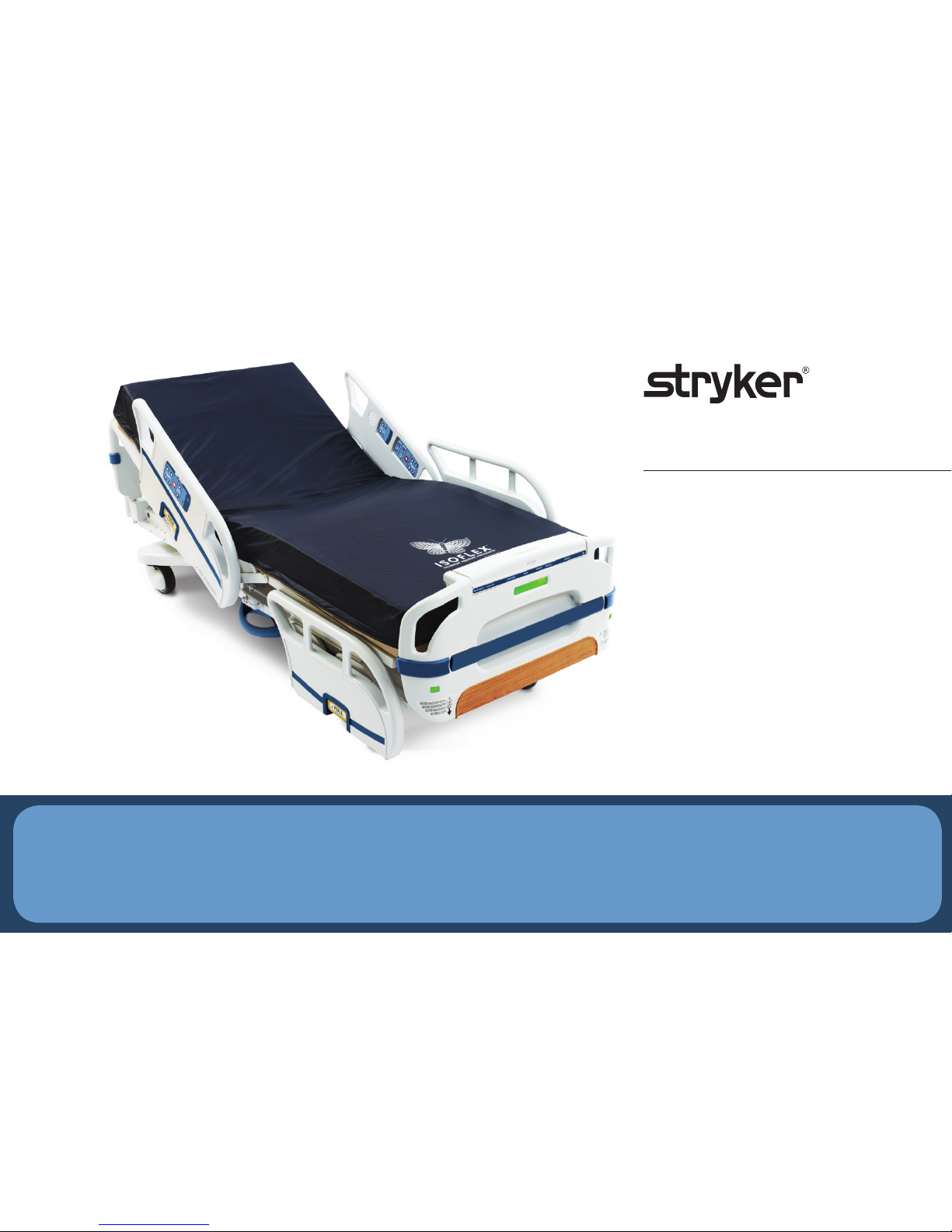
Stryker S3
™
Quick Start Guide
Always refer to the product label and/or operations manual before using any Stryker product.
Page 2
A
A
D
E
F
G
H
I
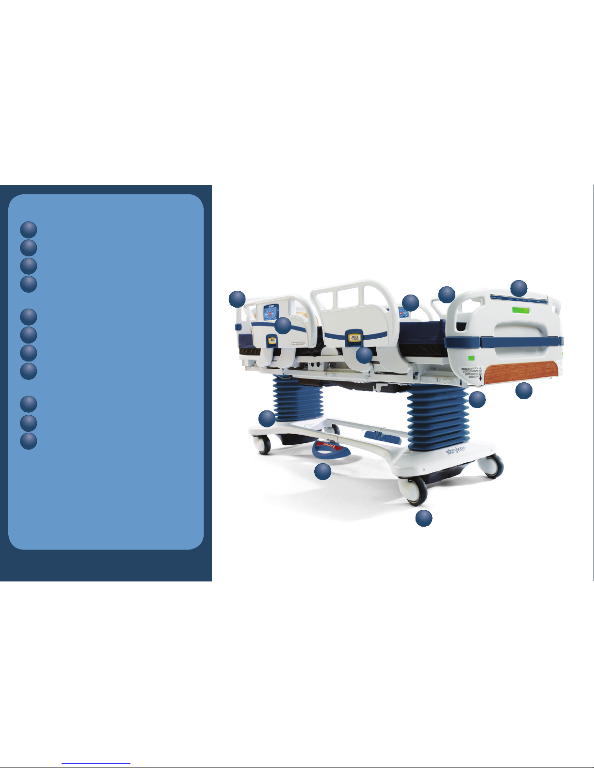
Overview
Headboard
Patient Controls
Siderails
Nurse Control
Panel
Footboard
120V AC Outlet (optional)
Caster
Siderail Release
Handle
Brake Pedal
Siderail Controls
Steer Pedal
A
B
C
D
E
F
G
H
I
J
K
B
C
J
K
Page 3

Scales
Notes:
Page 4
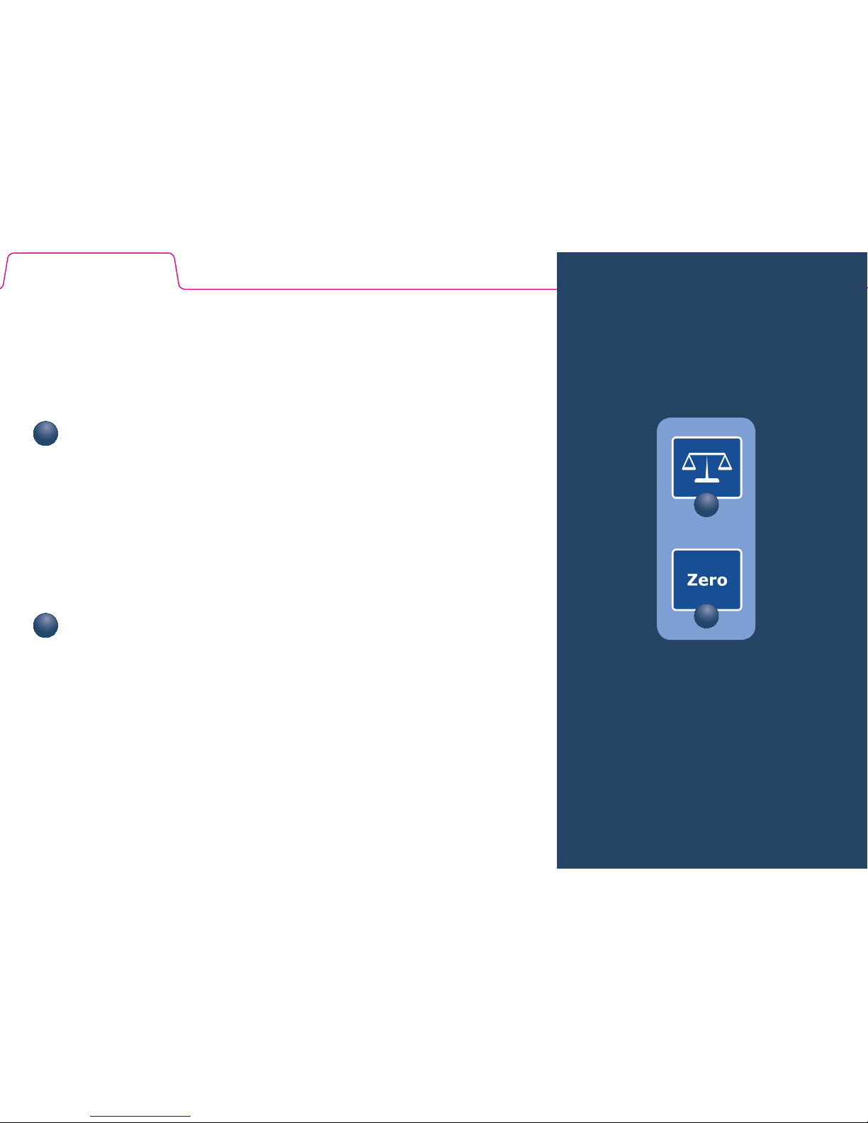
Nurse Controls: Bed Zero/Scale
(optional)
Zero the bed before patient admission. Before you help
the patient onto the bed, place all equipment, linens and
other items needed for the patient on the bed. Press and
hold Zero button and follow the instructions on the digital
display. All items located on the bed at the time the bed is
zeroed will not be added to the weight of the patient.
To take a weight, press and hold the Scale button.
1
2
1
2
Page 5

Bed Exit
Notes:
Page 6

Notes:
Page 7

Chaperone
®
Bed Exit System (optional):
Arm/Disarm
The bed exit system is a three-zone center-of-gravity system
that tracks the position of the patient’s body weight and
sounds an alarm when 50 percent of the patient’s body weight
exits a zone.
To Arm
Before arming, make sure the bed has been properly
zeroed without the patient in the bed.
Push and release the Arm/Disarm key. The largest zone
(Zone 1) light will illuminate when armed. The system will
automatically select the largest zone as default.
To change the zone, push the Zone key
until the light indicating the desired zone comes on.
To Dis ar m
To deactivate Bed Exit, push and hold the Arm/Disarm key.
The selected zone light will turn off.
Note: If the bed was not zeroed at patient admission,
prior to arming, the Chaperone Bed Exit System will not
operate properly.
1
3
3
1
2
2
Page 8
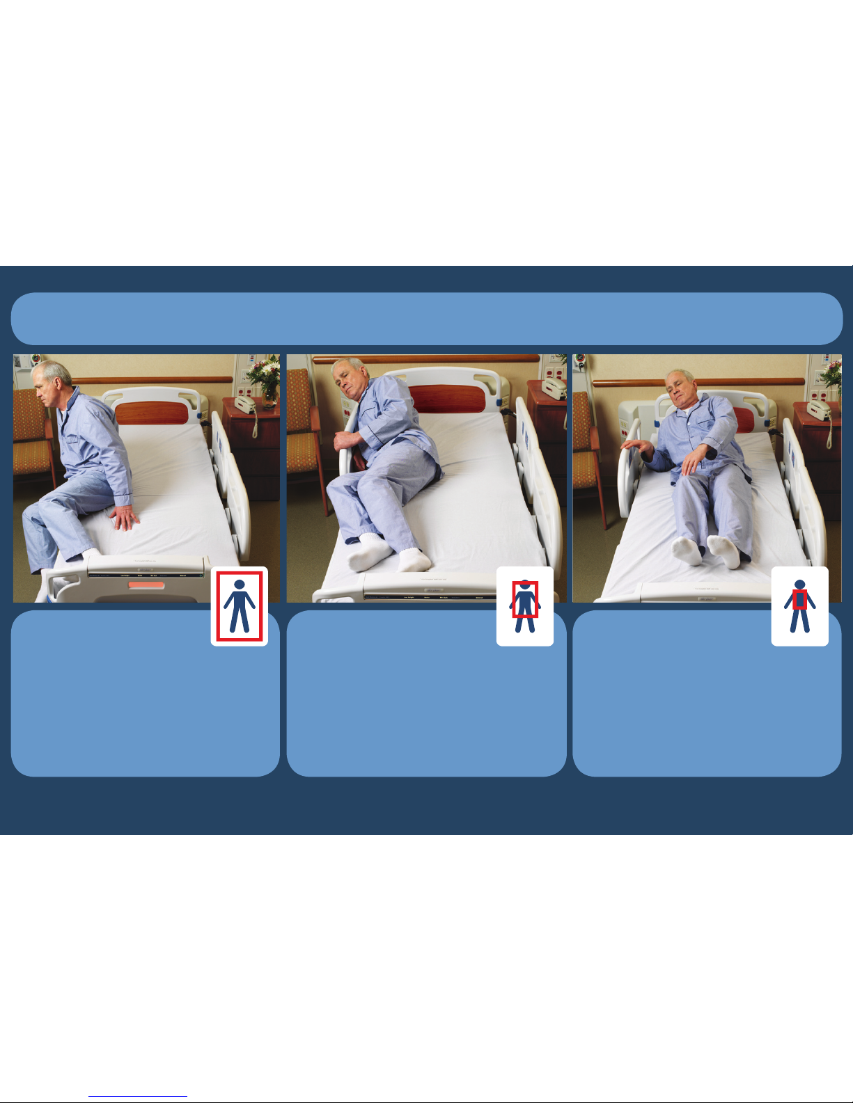
Zone 1 (default)
Allows the patient to move
freely on the bed, but alarms
when patient moves 50 percent of body weight out of
the designated zone.
Zone 2
Allows limited movement.
Alarms when the patient
approaches the siderail or
foot end of the bed.
Zone 3
Allows very minimal movement. Alarms when patient
moves out of the tightly
restricted zone.
Chaperone Bed Exit System: Zones
Page 9

iBed™ Awareness
Notes:
Page 10

Nurse Controls: i Bed™ Awareness (optional)
The iBed Awareness is a bed monitoring system that allows you to monitor the brakes, siderail
position, bed exit, low bed height and 30 degree HOB.
To Arm
Set the desired bed configuration.
Push and release the i BED key (all three green lights on
the footboard will illuminate).
If one of the parameters is changed, an amber light on the
footboard will flash indicating the bed is no longer in the
prescribed position. The digital display and nurse dashboard will indicate what has been altered.
To Dis ar m
To deactivate i Bed Awareness, push and hold the iBED (1)
key. The footboard lights will turn off.
1
1
2
1
2
2
Page 11

Controls
Notes:
Page 12

Notes:
Page 13

1
3
4 6 8
Nurse Controls: Bed Motion
Push to lower head end/raise foot end of bed.
(Trendelenburg position)
Push to lower foot end/raise head end of bed.
(Reverse Trendelenburg position)
Push to raise bed height.
Push to lower bed height.
Low Height will illuminate on the nurse dashboard
when the bed is at its lowest height.
Push to raise Fowler.
Push to lower Fowler.
Push to raise Knee Gatch.
Push to lower Knee Gatch.
1
3
4
5
6
7
8
2
2
5
7
Page 14

Nurse Controls: Bed Motion Locks
Bed Motion Lock*
Locks all motion on bed, including siderail controls and
foot end controls. Button will illuminate when activated.
Fowler 30°+ Lock*
Raises the Fowler to 30° and locks out the Fowler control
at all locations. Fowler 30°+ on the nurse dashboard will
illuminate when activated.
Patient Fowler Lock*
Locks out Fowler control at all siderail locations. The
button will illuminate when activated.
Patient Gatch Lock*
Locks out Gatch control at all locations. The button
will illuminate when activated.
Patient Bed Up/Down Lock*
Locks out Bed Height control at all siderail locations. The
button will illuminate when activated.
* Press and hold the lock button to unlock.
1
3
Note: The Fowler will not go below
30° once the Fowler 30°+ lock is
activated.
4
5
1
3 54
2
2
Page 15

Nurse Controls: Main Menu Features
Change Scale Units (lb or kg)
Press the Menu button.
Scroll down using the arrow keys to Scale Units and
press the ENTER button.
Select lbs or kg and press the ENTER button.
To Change Equipment
1. Select Change Equip. in the menu then press and hold
the ENTER button.
2. When the Add/Remove screen appears, add or remove
any equipment.
3. Press the ENTER button
4. Equipment Changed will be displayed when the system
completes the Change Equipment Adjustment. The status
screen will then display the weight of the patient only.
1
3
2
1 3
2
Page 16

Emergency CPR
Button
A CPR button can be found on
the footboard control panel.
To Activate
Press and hold the CPR
button to get the bed to a
full flat position.
Cardiac Chair
Button
To Activate
Press and hold the
Cardiac Chair button to
put the bed into a cardiac
chair position. This button
is located on both head
end siderails and the nurse
controls.
1
1
2
2
Page 17

Frame
Notes:
Page 18
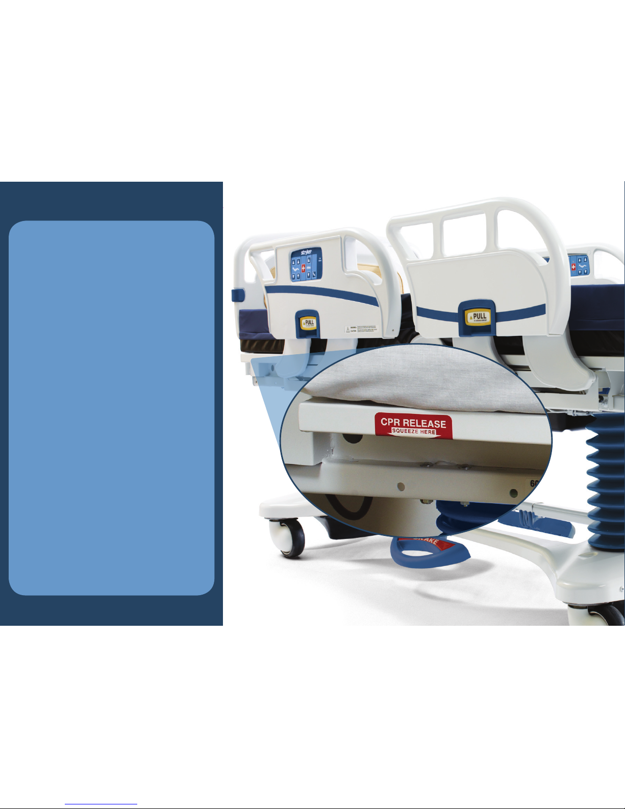
Emergency CPR
Release
The CPR release is located
under the sleep deck near the
top of the head end of the bed
on both sides.
To Activate
Squeeze one of the two
release handles, located
beneath the red CPR Release
labels, and the Fowler can be
quickly guided down to a flat
position.
For Your Safety
A CPR compression board
(opti o n a l) can be found on the
back of the headboard for
immediate use if a crash cart is
not available.
Page 19

Integrated Pump
Holder
Located on the footboard and
used to hang additional
equipment to the bed such as
CPMs or SCD machines.
For Your Safety
A 120V AC outlet (optional) is
conveniently located under the
footboard to help prevent trip
hazards.
Page 20

120V AC Outlet
(optional)
A 120V AC outlet is located
under the footboard at the foot
end of the bed. The 120V AC
outlet has its own power cord
located at the head end of the
bed and marked with a white
tag.
To Activate
Plug desired equipment into
120V AC outlet.
Plug in the power cord that
has a white tag (at the head
end of the bed).
Page 21

Full Upright Position
Grasp the top of the siderail,
pull outward and swing up
until it locks into the full
upright position.
Intermediate Position
Grasp the siderail release and
rotate the siderail until it locks
in the intermediate position.
Full Down Position
Grasp the siderail release
handle and rotate the siderail
until it is completely lowered.
Siderail Positions
Precision siderails are BackSmart™ designed with one-hand operation and intermediate support
positions for patient assistance during bed entry and exit.
“Precision Siderails — Where You Need Them, When You Need Them”
Page 22

1
Foot Prop Usage
The foot prop is located at the
foot end of the bed under the
Knee Gatch.
To Activate
Raise Knee Gatch and
swing foot prop towards
the foot end of the bed.
To lower, swing foot prop
towards the head end of
the bed.
1
2
2
Page 23

Foley Bag Hooks
Foley bag hooks are
located at two locations
on both sides of the frame;
under the frame below the
seat section and at the
foot end of the frame. The
isolated Foley bag hooks
are located at the foot end
of the bed on top of the
lift header.
Ease of Use
The patient weight reading
on the scale system will
not be affected when the
isolated Foley bag hooks
are used.
B
B
A
A
Page 24

Nightlight
The switch that turns the
nightlight on and off is located
under the litter deck section on
the patient’s left side.
Page 25

Centrally Located
Brakes
To Activate
Press to set the brake.
Press again to release
the brake.
For Your Safety
LED lights located on the
outside of the head end
siderails and on the nurse
dashboard will blink when the
brakes are not engaged.
In addition, an audible alarm
can be turned on using the
Advanced Menu Options.
1
1
2
2
Page 26
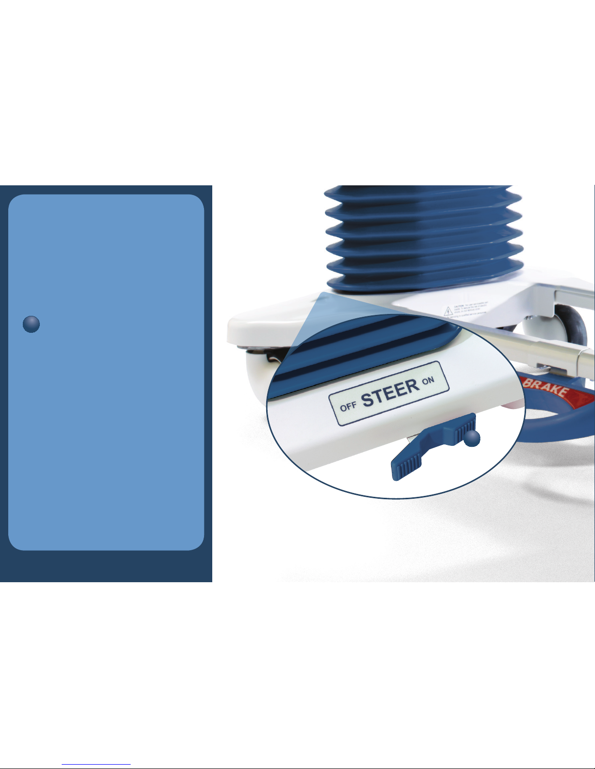
Steer Pedal
Operation
The Steer Pedal is located on
the base of the bed behind the
head board.
To Activate
Push in on one side or
the other of the triangular
Steer Pedal to engage
(ON) or disengage (OFF).
For Your Safety
When the ON side is pressed,
the front right caster cannot
swivel. It is locked parallel to
the long axis of the bed, to
keep the bed straight and
provide a pivot point.
1
1
Page 27

Stryker S3
Safe. Simple. Secure.
For additional questions, please contact your local Stryker
Account Manager.
Page 28

ÌÊ,i«>ViiÌÃ
/À>Õ>]ÊÝÌÀiÌiÃÊEÊivÀÌiÃÊ
À>>Ýv>V>
-«i
}VÃ
-ÕÀ}V>Ê*À`ÕVÌÃ
iÕÀÊEÊ /
ÌiÀÛiÌ>Ê*>
>Û}>Ì
`ÃV«Þ
ÕV>ÌÃ
>}}
*>ÌiÌÊ>ÀiÊEÊ>`}ʵիiÌ
-ʵիiÌ
3800 E. Centre Ave.
Portage, MI 49002 U.S.A.
t: 269 329 2100 f: 269 329 2311
toll free: 800 787 9537
www.stryker.com
The information presented in this brochure is intended to demonstrate a Stryker product.
Always refer to the package insert, product label and/or operations manual before using any
Stryker product. Products may not be available in all markets. Some features indicated in this
Quick Start Guide are options are and may not be configured on all products. Product availability is subject to the regulatory or medical practices that govern individual markets. Please
contact your Stryker Account Manager if you have questions about the availability of Stryker
products in your area.
Products referenced with ™ designation are trademarks of Stryker.
Products referenced with ® designation are registered trademarks of Stryker.
3006-029-001 Rev A
Copyright © 2009 Stryker
Printed in USA
 Loading...