

Page 1
CHROMOPHARE®
Surgical Lights, Single and Combination Lights
Service and Parts Manual
Page 2

Page 3

S
Table of Contents
1. Warnings and Cautions ....................................................................................................................... 1
2. Product Symbols ................................................................................................................................. 2
3. ESD Procedure .....................................................................................................................................3
3.1. Electrostatic Discharge ......................................................................................................................3
3.2. Electrostatic Dissipative Wrist-Straps ...............................................................................................3
4. Comprehensive Tools .......................................................................................................................... 4
4.1. Required Tools.....................................................................................................................................4
4.2. Optional Tools .....................................................................................................................................4
5. System Architecture ............................................................................................................................ 5
5.1. Model Plate .........................................................................................................................................5
5.2 CHROMOPHARE (Ceiling) ..................................................................................................................6
5.2.1 Single Light, Classic Cardanic Unit (A.C) .......................................................................................... 6
5.2.2 Light Combination, Classic Cardanic Unit (A.C) ............................................................................. 6
5.2.3 Single Light, Flat Cardanic (N.C.) ....................................................................................................... 7
5.2.4 Light Combination, Flat Cardanic (N.C) ........................................................................................... 7
5.2.5 Single Light, New Flat Cardanic (N.F.C) ............................................................................................ 8
5.2.6 Light Combination, New Flat Cardanic (N.F.C) ............................................................................... 8
5.3 CHROMOPHARE E 520, E 550, E 558, F 528, F 628 (Wall) ............................................................... 9
5.3.1 Single Light, Classic Cardanic (A.C) ................................................................................................... 9
5.3.2 Single Light, Flat Cardanic (N.C) ........................................................................................................ 9
5.3.3 Single Light, New Flat Cardanic (N.F.C) .......................................................................................... 10
5.4. CHROMOPHARE E 520, E 550, E 558, F 528, F 628 (Mobile) .........................................................11
5.4.1 E Series With Emergency Power .......................................................................................................11
5.4.2 E Series Without Emergency Power ................................................................................................. 12
5.5 F Series (Mobile) ...............................................................................................................................13
5.6. Chromophare VPA Video/Power Arm ............................................................................................14
5.6.1 VPA Single (Stand-Alone) Mount ..................................................................................................... 14
5.6.2 VPA Video Power Arm/Light Combination .................................................................................... 14
5.6.3 VPA Video Power Arm/Light/Flat Panel Combinatio ...................................................................15
5.6.4 Shoulder Mount VPA Video Power Arm/Light/Light/Flat Panel/Shoulder ............................. 15
5.7. ChromoView Monitor Supports(Yoke) ..........................................................................................16
5.7.1 Single Monitor Support Arm ............................................................................................................. 16
5.7.2 Dual Monitor Support Arm ............................................................................................................... 16
6. Unpacking/Packing ........................................................................................................................... 17
6.1 Transport Inspection ........................................................................................................................17
7. Suspension Maintenance ..................................................................................................................19
7.1. Leveling Suspensions .......................................................................................................................19
7.2. Replacing the Ceiling Tube .............................................................................................................20
7.3 Replacing a Suspension for Lights and Light/Flat Panel Combination Suspensions ..............22
7.4. Replacing the Horizontal Arm on a Wall Single Light ..................................................................24
7.5. Replacing a Spring Arm for Light Head or Flat Panel Support Arm (Ceiling Suspension) ......25
i
Page 4

S
7.6. Replacing Spring Arm for Wall Mounted Single Light ................................................................27
7.7. Replacing Spring Arm for VPA .........................................................................................................29
7.8. Replacing VPA POD ..........................................................................................................................29
7.9. Replacing the Light Head or Monitor Yoke ..................................................................................29
7.9.1 Classic Cardanic for Light Head or Monitor Yoke .........................................................................30
7.9.2 Flat Cardanic .........................................................................................................................................31
7.9.3 New Flat Cardanic (N.F.C) .................................................................................................................. 32
7.10. Adjusting Suspension Brakes for Lights, Flat Panels, and VPA ....................................................35
7.10.1 Horizontal Arm Brakes........................................................................................................................35
7.10.2 Light/Flat Panel Spring Arm Brakes .................................................................................................35
7.10.3 Cardanic Brakes on a Classic ............................................................................................................36
7.10.4 Cardanic Brakes on the Flat Cardanic ............................................................................................ 36
7.10.5 Cardanic Brakes on New Flat Cardanic .......................................................................................... 36
7.10.6 Light Head Brakes ................................................................................................................................ 37
7.10.7 VPA Spring Arm Brakes ....................................................................................................................... 37
7.11. Adjustments for Lights, Flat Panel, and VPA Suspensions ...........................................................38
7.11.1 Spring Arm Height Adjustment for Lights and Flat Panel Spring Arms .................................. 38
7.11.2 Flat Cardanic Height Adjustment ...................................................................................................38
7.11.3 Height Adjustment for NFC Spring Arms ....................................................................................... 39
7.11.4 Counter Balancing the Spring Arm for Lights and Flat Panels .................................................39
7.11.5 VPA Spring Arm Up/Down Brakes ....................................................................................................40
7.11.6 VPA Height Stop Detents .................................................................................................................... 41
7.12 Spring Arm Wire Harness Replacement for Lights .......................................................................41
7.13 Spring Arm Cover Replacement ....................................................................................................45
7.15 Dual Flat Panel Arm Maintenance ..................................................................................................47
7.15.1 Dual Flat Panel Spring Arm Counterweight Adjustment ........................................................... 47
7.16 Servicing Suspension Stop Rotation .............................................................................................51
7.16.1.1 Changing/Replacing Stop Location ................................................................................................ 51
7.17 Horizontal Arm Maintenance .........................................................................................................53
7.17.1 Replacing Height Compensation Tube (HCT) on Horizontal Arm ........................................... 53
7.17.2 Replacing internal wiring on Horizontal Arm (light suspension only) ................................... 55
7.18 Replacing Suspension Bottom Cap (Jar Cover) ............................................................................57
7.19 Suspension Mounted EndoLite ......................................................................................................58
7.19.1 General Information ........................................................................................................................... 58
7.19.2 Endo Repair ........................................................................................................................................... 61
7.20 Replacing the Slip Ring (Commutator) on an F Gen Light ..........................................................62
8. Cardanics
8.1 Cardanic Replacement .....................................................................................................................66
9. Light Head Maintenance ...................................................................................................................82
9.1 Light Handles / Focus Mechanism ................................................................................................82
9.2 F 528/628 (F-Gen) Light Head Maintenance .................................................................................83
9.3 E558/668/778 (E LED) Light Head Maintenance ..........................................................................84
ii
........................................................................................................................................... 66
8.1.1 Cardanic Replacement for EXX0/EXX5 Light Heads (Halogen/HID)........................................ 66
8.1.2 Cardanic Replacement for EXX8 Light Heads (E LED) ................................................................. 68
8.1.3 Cardanic Replacement for FXX8 Light Heads (F-Gen) ................................................................ 71
8.1.4 F-Generation Cardanic Security Tool: ............................................................................................. 71
9.1.1 Light Handle Replacement ................................................................................................................ 83
Page 5

S
9.3.1 Accessing the light head internals ................................................................................................... 84
9.3.2 Lower Glass Replacement .................................................................................................................. 85
9.3.3 Frame/Frame Seal/Glass Seal Replacement ................................................................................. 85
9.3.4 Distribution Board ............................................................................................................................... 87
9.3.5 LED Module replacement ..................................................................................................................89
9.3.6 Light Head Reassembly (Refer to 9.3.1 for Illustrations) ............................................................. 91
9.4 E550/650 (Halogen) and E655/805 (HID) Light Head Maintenance ..........................................92
9.4.1 Dome Removal and Replacement Exx0/Exx5 ............................................................................... 92
9.4.2 EndoLite ................................................................................................................................................ 93
9.4.3 Lower Glass Assembly ......................................................................................................................... 94
9.4.4 Replacing the Filter Glass Assembly ................................................................................................ 95
9.4.5 Circuit Boards .......................................................................................................................................98
9.4.6 Cuircuit Board Replacement ............................................................................................................. 98
9.4.6.1 CPU Board...............................................................................................................................98
9.4.6.2 Camera Board (only with in-light option) ............................................................................99
9.4.6.3 Dimming Control Board (E550/650) .................................................................................. 100
9.4.6.4 EVG Board (E655/805) ......................................................................................................... 100
9.5 Light Head Dome Cover Replacement for F528/F628 .............................................................. 101
10. Control Panels ..............................................................................................................................104
10.1 Halogen and HID light controls (Exx5/Exx0) .............................................................................. 104
10.2 LED Light controls - E LED and F-Generation (Exx8/Fxx8) ....................................................... 108
11. Power Supply Service Instructions ............................................................................................... 117
11.1 General Information ...................................................................................................................... 117
11.2 SK Boxes .......................................................................................................................................... 119
11.3 Tube mounted power supplies.................................................................................................... 121
11.4 Camera distribution board ........................................................................................................... 122
12. Preventative Maintenance ............................................................................................................ 123
13. Contact Information .....................................................................................................................124
iii
Page 6
S
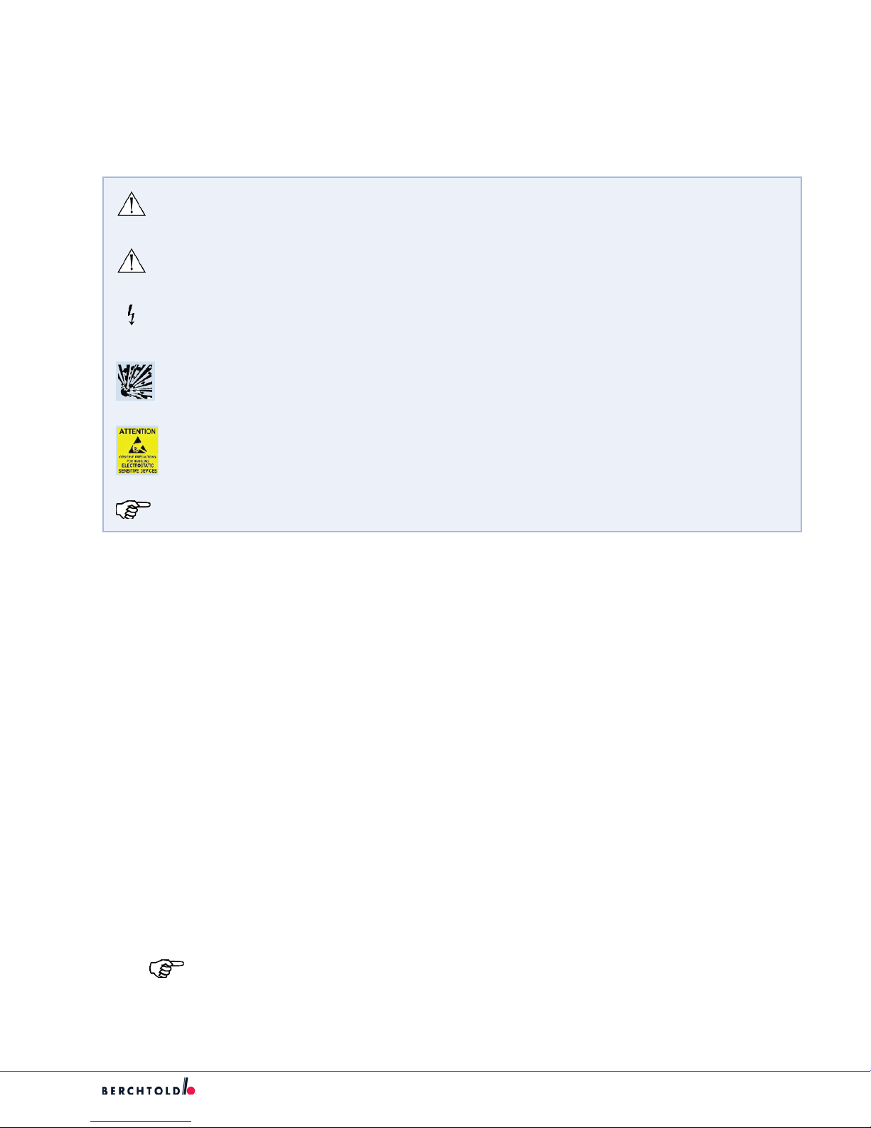
1. Warnings and Cautions
Please read this manual and follow its instructions carefully. The words WARNING, CAUTION, and Note carry
special meanings and should be carefully reviewed:
WARNING: The personal safety of the patient or user may be involved. Disregarding this
information could result in injury to the patient or user.
CAUTION: Special service procedures or precautions must be followed to avoid damaging the
instrument.
WARNING: A lightening bolt is intended to warn of the presence of hazardous voltages. Refer
all service to authorized personnel.
WARNING: Potential explosion hazzard.
WARNING: A yellow box with a hand within a triangle is intended to warn the user of the
presence of an electrostatic sensitive device. Follow ESD prevention procedures.
Note: Special information to make maintenance easier or important information more clear.
To avoid potential serious injury to the user or the patient or both and to avoid damage to this device, the
user must adhere to the following warnings and cautions.
• Do not add additional weight to the surgical lights.
• Do not place anything over the surgical lights.
• Do not look directly into the surgical light while powered on.
• Do not operate the surgical light if any component of the light (such as the glass) is damaged.
1. Stryker trained personnel are the only personnel authorized to install the equipment described in this
manual.
2. Attempt no repairs or adjustments, unless specically instructed to do so in this manual.
3. Disconnect the unit from the electric outlet before inspecting or servicing system components. Note that
more than one electrical supply may be used. Disconnect all power sources before inspecting.
4. The electrical installation of the operating room must comply with any applicable IEC, CEC, NEC
requirements as well as the local codes and pre-installation manual.
5. Do not use accessories or cables other than those provided or recommended. Such use may result in
increased electromagnetic emissions or decreased electromagnetic immunity of the equipment or
system. Use of components or accessories not recommended by Stryker/Berchtold may result in reduced
performance or system breakdown.
Note: Test Equipment after servicing.
1
Page 7
S
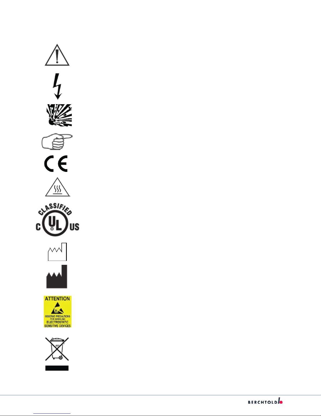
2. Product Symbols
An exclamation mark within a triangle is intended to alert the user to the presence of
important operating and maintenance (service) instructions in the literature accompanying the product.
A lightning bolt within a triangle indicates the presence of hazardous voltage. Refer all
service to authorized personnel.
Denotes oxygen explosion hazard.
Denotes usage tips and useful information.
Denotes compliance to European Community Directive 93-42-EEC.
Indicates hot surfaces.
Denotes compliance to UL 60601-1, CAN/CSA C22.2 No. 601.1, CAN/CSA C22.2 NO.
601.2XX
Denotes the date the equipment was manufactured.
Denotes the manufacturer of the device.
A yellow box with a hand within a triangle is intended to warn the user of the presence
of an electrostatic sensitive device. Follow ESD prevention procedures.
In accordance with European Community Directive 2002/96/EC on Waste Electrical and
Electronic Equipment, this symbol indicates that the product must not be disposed of
as unsorted municipal waste but should be collected separately.
Note: The device does not contain any hazardous materials.
Legal regulations may include specications regarding the disposal of this product.
Please contact Stryker/Berchtold to withdraw this device from service for discard.
2
Page 8

S
3. ESD Procedure
3.1. Electrostatic Discharge
Static electricity is a stationary form of electrical charge. This charge is due to the transfer of electrons within
a body or from one body to another. The magnitude of the charge depends on the size, shape, composition
and electrical properties of the substance that make the bodies.
Once a body develops a static charge, it will look for a conductive surface to discharge. This is called
Electrostatic Discharge (ESD). This discharge is only felt when the charge is larger than 3500 volts, yet many
components are sensitive well below this level.
Potentially dangerous levels of ESD can generate from the following common manufacturing sources:
• Plastic (bags, containers, binders)
• Paper (procedures, DHRs, pick slips)
• CRT Monitors
• Clothing
Subassemblies and equipment that contain ESD sensitive devices (without adequate circuitry) are also ESD
sensitive.
Avoid sliding ESD sensitive components across other materials. Sliding materials together can create the
build up of an electrostatic charge.
3.2. Electrostatic Dissipative Wrist-Straps
Wrist-straps should be worn during the handling of ESD sensitive devices. The wrist-strap should contain an
internal 1Mohm resistor to protect the operator in the case of accidental high voltage being applied to the
workstation surface.
3
Page 9

S
4. Comprehensive Tools
4.1. Required Tools
• Genie lift or equipment lift, SLC-12 or equivalent
• Torpedo level
• Metric allen set
• Wrench Set
• Small and large phillips head
• Small and Large at head screw driver
• Snap ring plier
• Torque Wrench
• Spreader Forceps
• Screw Removal Tools
• Digital Level
• Wire Strippers
• Soldering Iron
4.2. Optional Tools
• Porta band saw
• Large hand le
• 1/2 inch Drill/Driver
• Tape measure
• Drill bit set
• Hand tool pouch
• Adjustable wrench
• Roofer’s square
• Hammer
4
Page 10
S
5. System Architecture
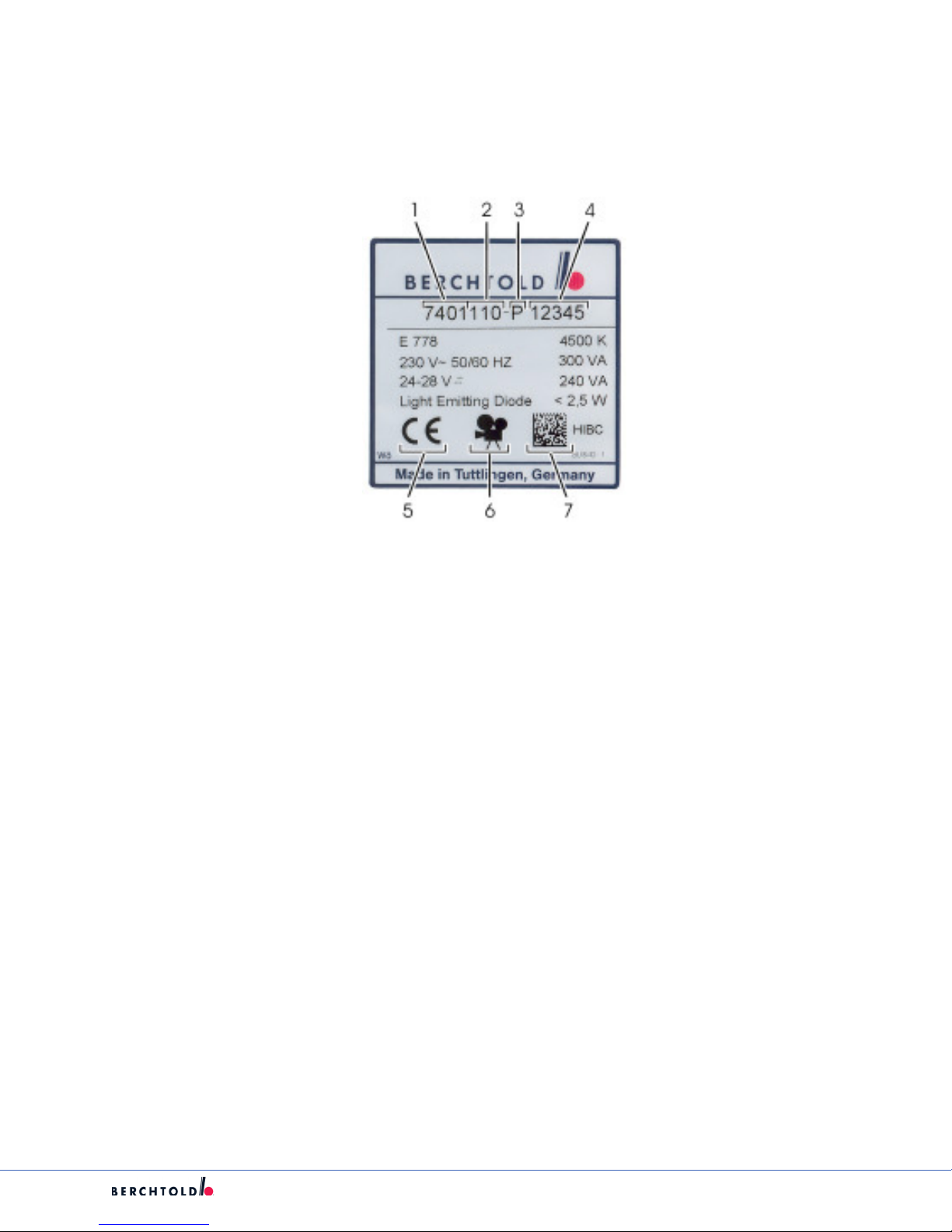
5.1. Model Plate
The Model Plate is located next to the suspension installation point on the housing of the Light Head or the
VPA Pod.
1. Version Number
2. Model Number
3. Year of Manufacture (A=1993, B=1994, etc.)
4. Sequential Numbering
5. CE Mark
6. Symbol for Camera Preparation (optional)
7. Health Industry Bar Code
5
Page 11
S
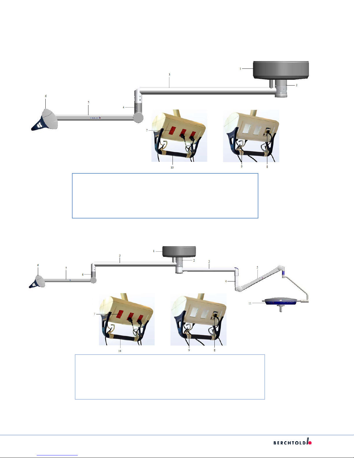
5.2 CHROMOPHARE (Ceiling)
The following sections apply to models E 520, E 550, E 558, E 650, E 655, E 668, E 778, E 800, E 805, F 528, F 628.
Note: Suspension in use applies to both E and F series Lights.
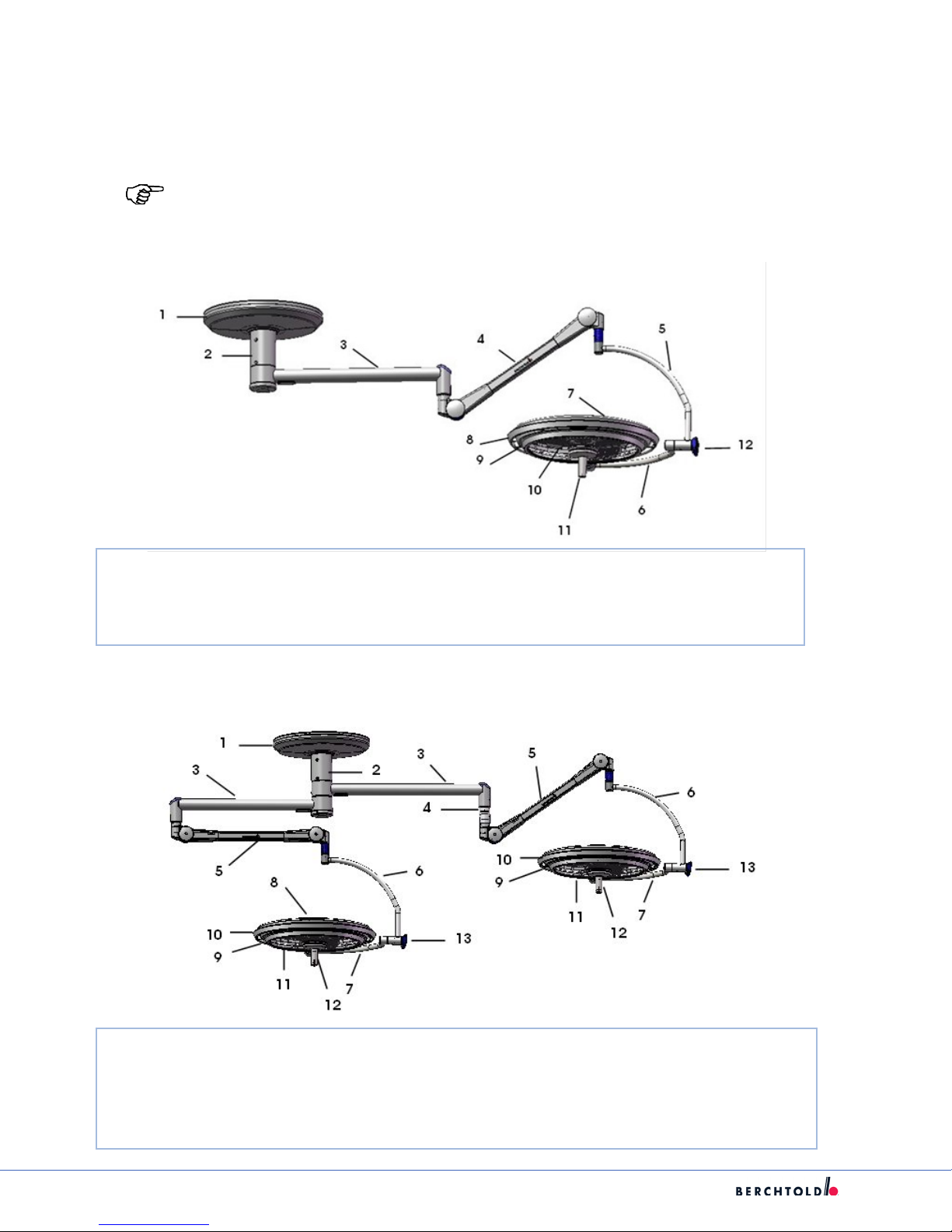
5.2.1 Single Light, Classic Cardanic Unit (A.C)
1. Ceiling Cover 5. Vertical Gimbal Joint 9. Panel Frame
2. Ceiling Tube Ø 125 mm 6. Horizontal Gimbal Joint 10. Light-Output Surface (Facing)
3. Horizontal Arm 7. Light Head Hood Support 11. Handle Assembly
4. Spring Arm 8. Rail 12. Control Unit
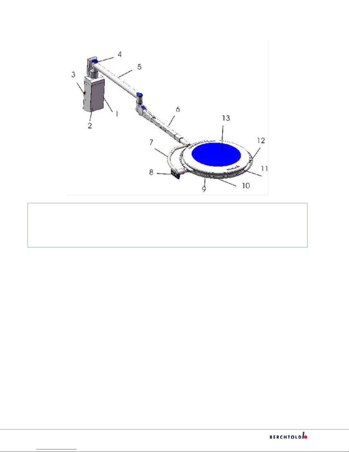
5.2.2 Light Combination, Classic Cardanic Unit (A.C)
1. Ceiling Cover 6. Vertical Gimbal Joint 11. Light-Output Surface (Facing)
2. Ceiling Tube Ø 125 mm 7. Horizontal Gimbal Joint 12. Handle Assembly
3. Horizontal Arm 8. Light Head Hood Support 13. Control Unit
4. Height Adjustment Tube 9. Panel Frame
5. Spring Arm 10. Rail
6
Page 12
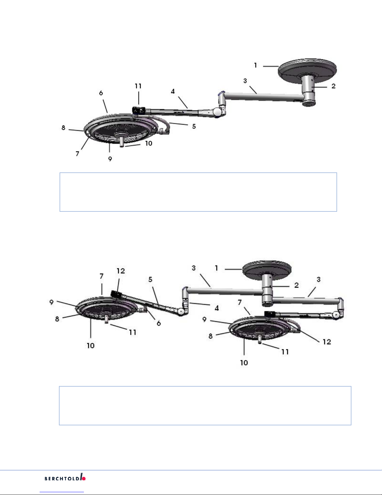
5.2.3 Single Light, Flat Cardanic (N.C.)
1. Ceiling Cover 5. Horizontal Gimbal Joint 9. Light-Output Surface (Facing)
2. Ceiling Tube Ø 125 mm 6. Light Head Hood Support 10. Handle Assembly
3. Horizontal Arm 7. Panel Frame 11. Control Unit
4. Spring Arm 8. Rail
S
5.2.4 Light Combination, Flat Cardanic (N.C)
1. Ceiling Cover 5. Spring Arm 9. Rail
2. Ceiling Tube Ø 125 mm 6. Horizontal Gimbal Joint 10. Light-Output Surface (Facing)
3. Horizontal Arm 7. Light Head Hood Support 11. Handle Assembly
4. Height Adjustment Tube 8. Panel Frame 12. Control Unit
7
Page 13
S
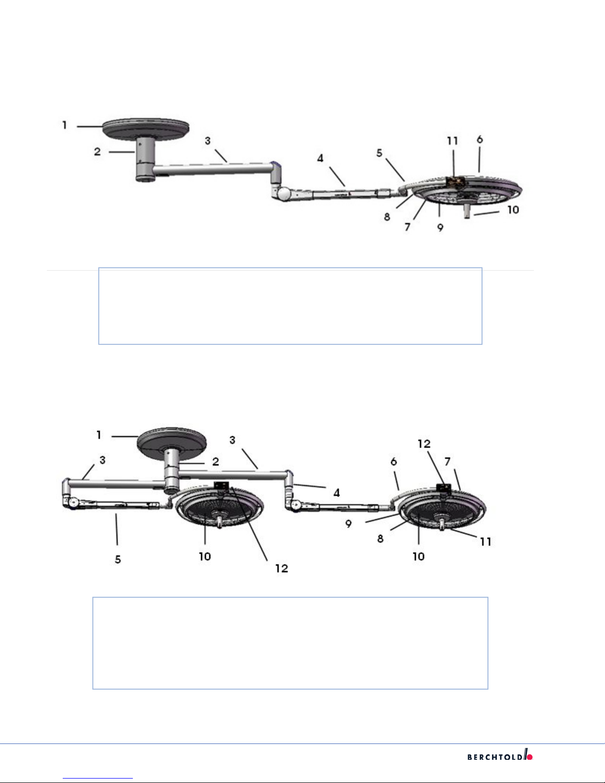
5.2.5 Single Light, New Flat Cardanic (N.F.C)
1. Ceiling Cover 6. Panel Frame
2. Ceiling Tube Ø 125 mm 7. Rail
3. Horizontal Arm 8. Light-Output Surface (Facing)
4. Spring Arm 9. Handle Assembly
5. Horizontal Gimbal Joint 10. Control Unit
5.2.6 Light Combination, New Flat Cardanic (N.F.C)
1. Ceiling Cover 7. Light Head Hood Support
2. Ceiling Tube Ø 125 mm 8. Panel Frame
3. Horizontal Arm 9. Rail
4. Height Adjustment Tube 10. Light-Output Surface (Facing)
5. Spring Arm 11. Handle Assembly
6. Horizontal Gimbal Joint 12. Control Unit
8
Page 14
5.3 CHROMOPHARE E 520, E 550, E 558, F 528, F 628 (Wall)
Note: Suspension in use applies to both E and F series Lights.
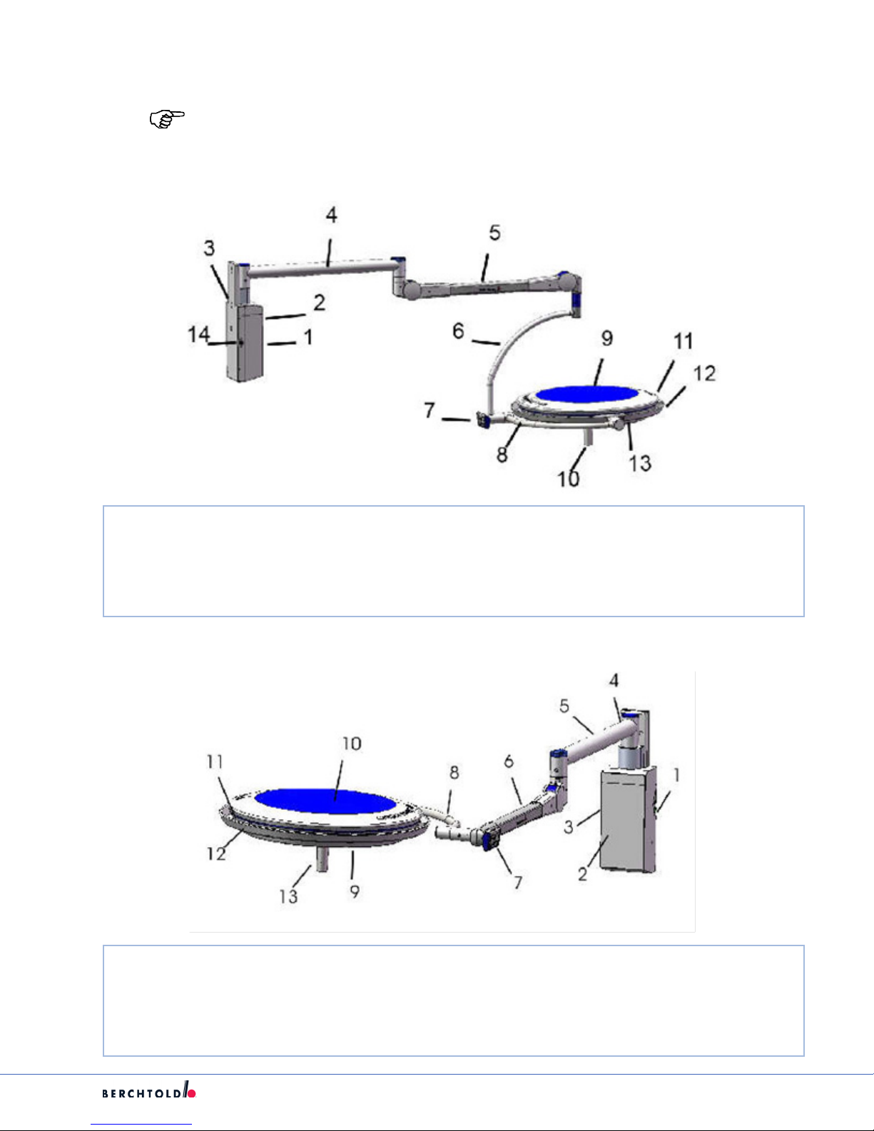
5.3.1 Single Light, Classic Cardanic (A.C)
S
1. Transformer Housing 6. Vertical Gimbal Joint 11. Panel Frame
2. Mains Switch 7. Control Unit 12. Rail
3. Wall Bracket 8. Horizontal Gimbal Joint 13. Underglass
4. Horizontal Arm 9. Light Head Hood Support 14. Camera Cable Connection Socket
5. Spring Arm 10. Handle Assembly
5.3.2 Single Light, Flat Cardanic (N.C)
1. Transformer Housing 6. Vertical Gimbal Joint 11. Panel Frame
2. Mains Switch 7. Control Unit 12. Rail
3. Wall Bracket 8. Horizontal Gimbal Joint 13. Underglass
4. Horizontal Arm 9. Light Head Hood Support 14. Camera Cable Connection Socket
5. Spring Arm 10. Handle Assembly
9
Page 15
S
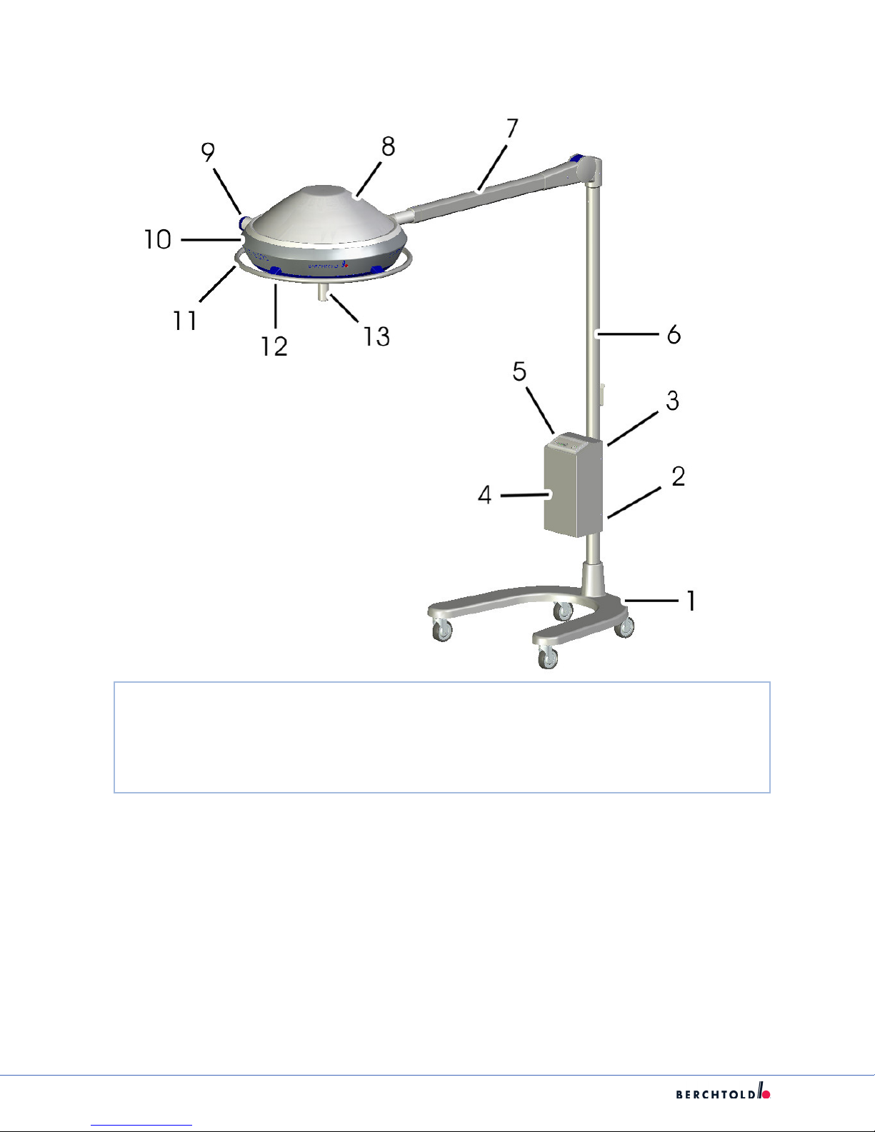
5.3.3 Single Light, New Flat Cardanic (N.F.C)
1. Mains Switch 6. Spring Armt 11. Panel Frame
2. Transformer Housing 7. Horizontal Gimbal Joint 12. Rail
3. Camera Cable Connection Socket 8. Control Unit 13. Light Head Hood Support
4. Wall Bracket 9. Underglass
5. Horizontal Arm 10. Handle Assembly
10
Page 16
5.4. CHROMOPHARE E 520, E 550, E 558, F 528, F 628 (Mobile)
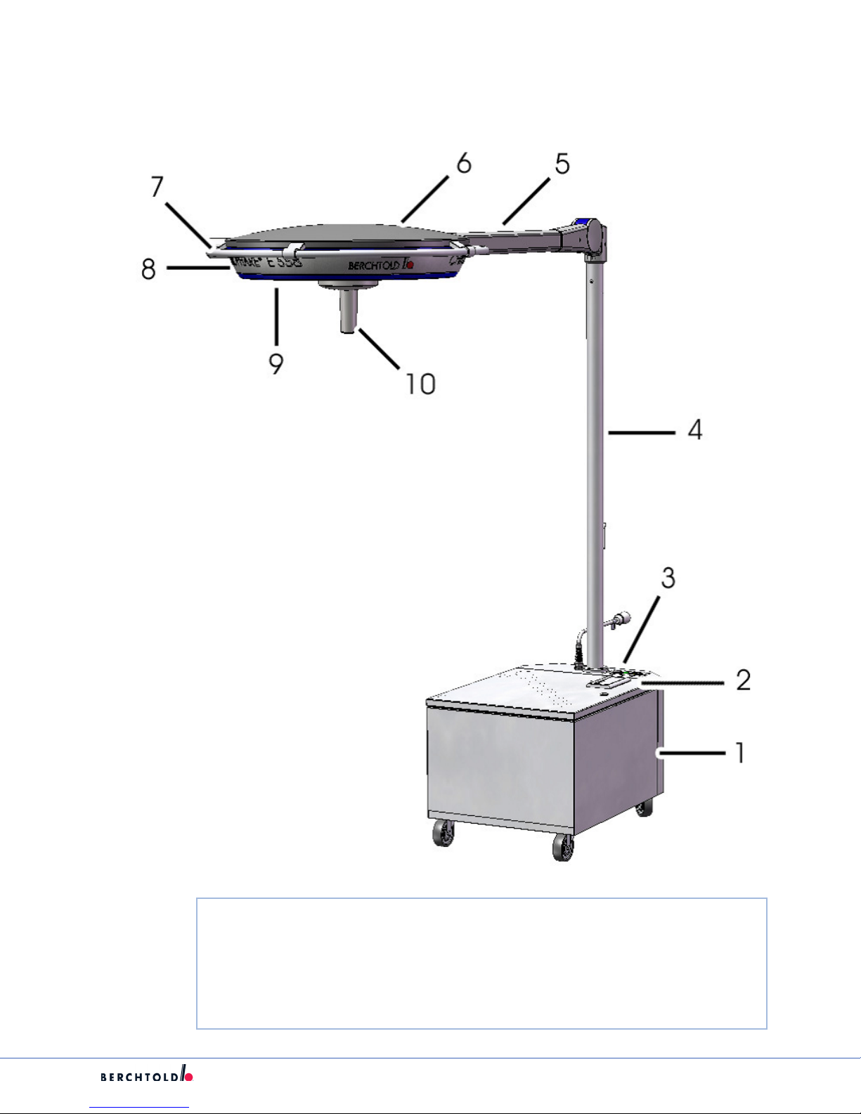
5.4.1 E Series With Emergency Power
S
1. Stand Base (control unit, main fuses, batteries, charger) 7. Side Shaft Control Panel
2. On/OFF Switch 8. Lamp Frame
3. Control Unit 9. Rail
4. Stand Pillar 10. Light-Emission Lens
5. Spring Arm 11. Hand Grip
6. Light Head Hood Holder
11
Page 17
S
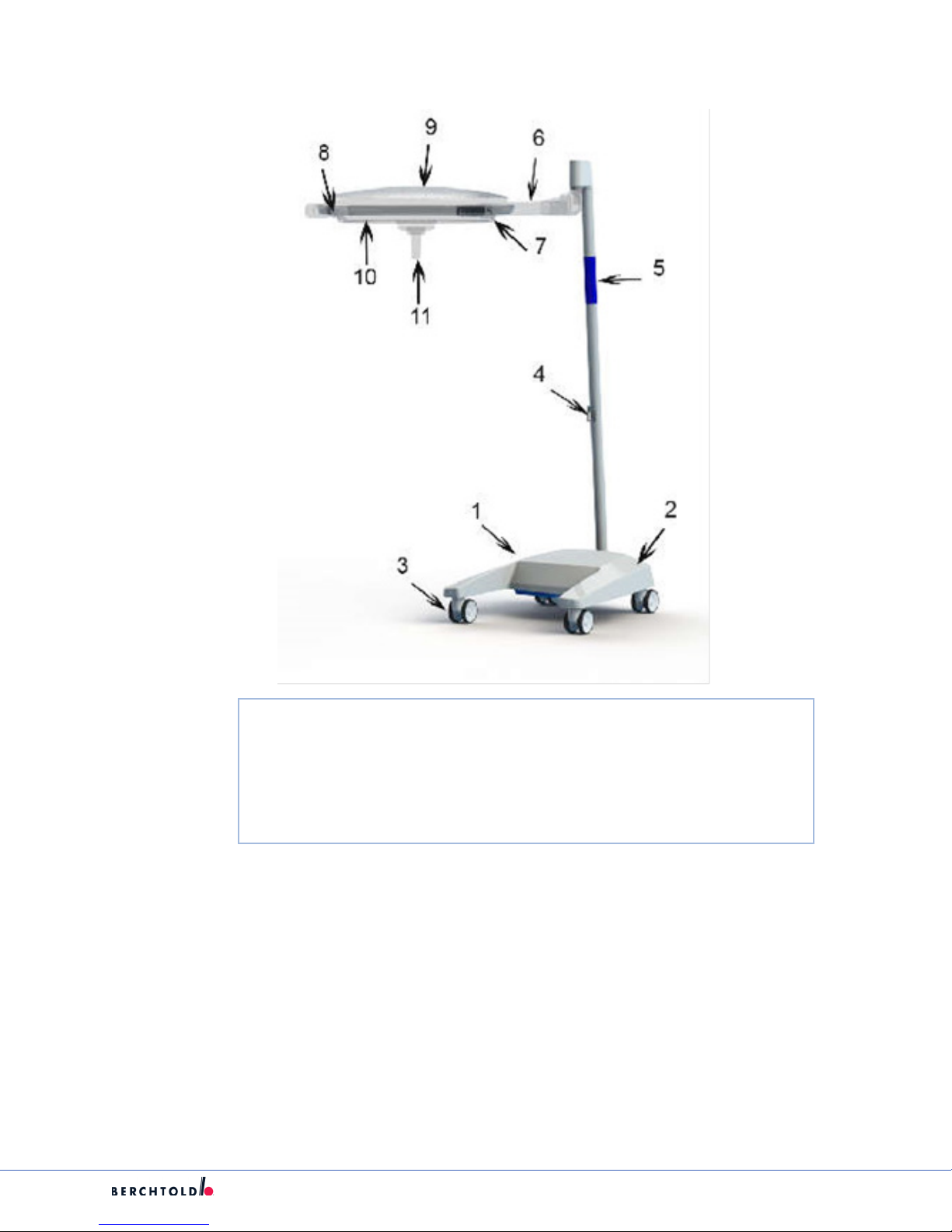
5.4.2 E Series Without Emergency Power
1. Base 6. Stand Pillar 11. Rail
2. Main Fuse Mount 7. Spring Arm 12. Light-Emission Lens
3. Connector Port for Camera Cable 8. Light Head Hood Holder 13. Handle
4. Transformer, Electronics 9. Side Shaft Control Panel
5. Control Unit 10. Lamp Frame
12
Page 18
5.5 F Series (Mobile)
S
1. Stand Base 7. Light Fram
2. Charge Level Display and On/OFF Switch 8. Rail
3. Double Castors with Parking Brake 9. Light Head Cover Casting
4. Cable Hook 10. Underglass
5. Tubular Stand 11. Replaceable Sleeve
6. Spring Arm
13
Page 19
S
5.6. Chromophare VPA Video/Power Arm
5.6.1 VPA Single (Stand-Alone) Mount
1. Ceiling Cover 6. Service Pod
2. Ceiling Tube Ø 125 mm 7. 115V Duplex Power Outlet
3. Horizontal Arm 8. Data Plates
4. Height Adjustment Tube 9. Cord Management
5. Spring Arm 10. AccessHandle
5.6.2 VPA Video Power Arm/Light Combination
1. Ceiling Cover 7. 115V Duplex Power Outlet
2. Ceiling Tube Ø 125 mm 8. Data Plates
3. Horizontal Arm 9. Cord Management
4. Height Adjustment Tube 10. Access Handle
5. Spring Arm 11. Light Head
14
Page 20

5.6.3 VPA Video Power Arm/Light/Flat Panel Combinatio
1. Ceiling Cover 7. 115V Duplex Power Outlet
2. Ceiling Tube Ø 125 mm 8. Data Plates
3. Horizontal Arm 9. Cord Management
4. Height Adjustment Tube 10. Access Handle
5. Spring Arm 11. Light Head
6. Service Pod 12. Monitor Yoke
S
5.6.4 Shoulder Mount VPA Video Power Arm/Light/Light/Flat Panel/Shoulder
1. Ceiling Cover 7. 115V Duplex Power Outlet
2. Ceiling Tube Ø 125 mm 8. Data Plates
3. Horizontal Arm 9. Cord Management
4. Height Adjustment Tube 10. Access Handle
5. Spring Arm 11. Light Head
6. Service Pod 12. Monitor Yoke
15
Page 21

S
5.7. ChromoView Monitor Supports(Yoke)
5.7.1 Single Monitor Support Arm
5.7.2 Dual Monitor Support Arm
16
Page 22
S
6. Unpacking/Packing
6.1 Transport Inspection
Warning: Use caution when lifting heavy objects to avoid serious bodily injury or
damage to the equipment.
Check the delivery immediately for completeness and any damage during transport.
For obvious damage to the component delivered contact technical support for proper disposition and
replacement component.
To limit damage, use the original packaging when returning a product to Stryker/Berchtold. Provide the
following information: Account’s Name and Address, Serial Number(model plate), and a description of the
defect.
Caution: The Light Head may sustain damage during transport as a result of inadequate
packaging.
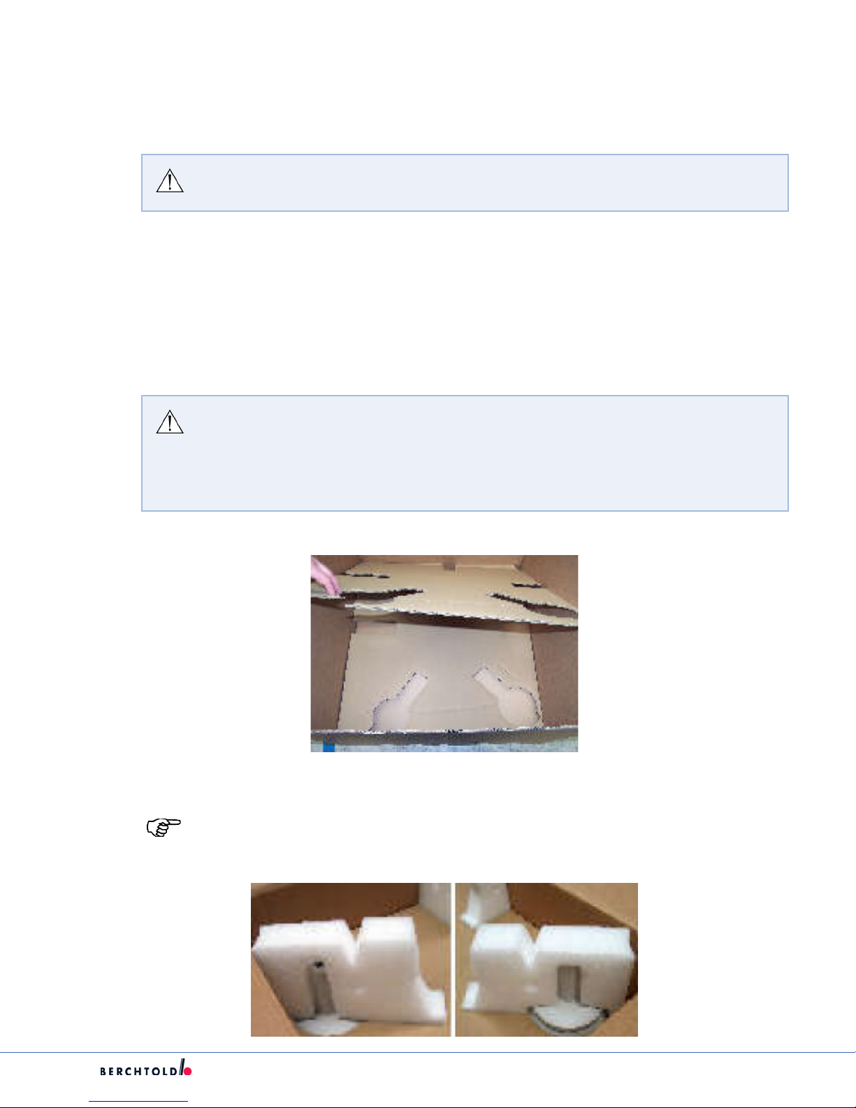
1. Secure the Light Head using the carton segments and cushioning provided.
2. Place the cushioning into the corresponding recesses.
3. Observe the following handling procedure.
1. Place two carton segments into the carton with the cut-out facing upwards.
2. Place the sterilizable replaceable sleeves into the corresponding recesses provided.
Note: If 2 replaceable sleeves are sent together the focusing unit must be placed into the
recess with one replaceable sleeve attached.
17
Page 23
S
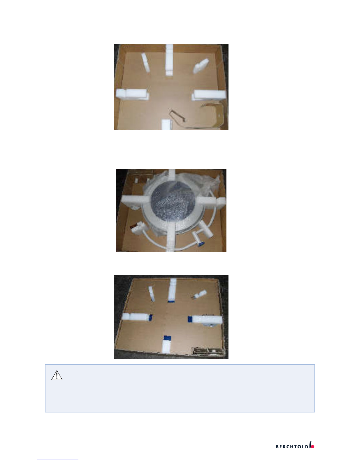
3. Place the cushioning into the corresponding recesses as shown in the illustration.
4. Position the Light Head in accordance with the cut-out and in accordance with the diagram.
5. The cardanic suspension MUST be pressed into the cushioning.
6. Place the carton segment onto the light head such that the recesses match the cushioning.
Caution: If the cushioning is not placed into the correct cut-outs and the cardanic
suspension is not pressed rmly into the cushioning, there is a risk that the Light Head
could sustain damage during transport.
1. Place the cushioning into the appropriate recesses.
2. Ensure that the light head is held securely by the cushioning.
18
Page 24
S
7. Suspension Maintenance
7.1. Leveling Suspensions
1. Single or dual light or any combination on suspension, place the light head of at panel under the
center of the mount.
Example:
Dual Suspension with
Lightheads Under Center
2. Once the light heads are under center, place a level on the top of the suspension arm and attach with
wire ties or any other means available.
3. Remove the ceiling cover.
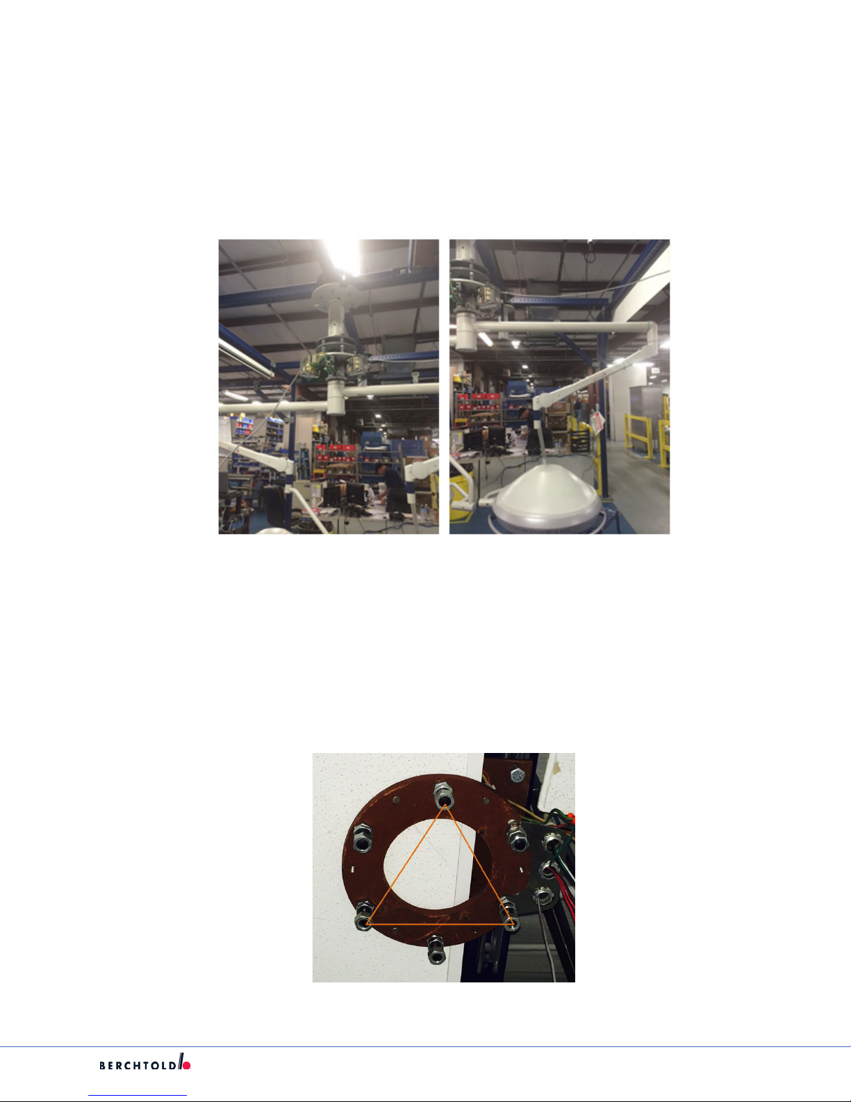
4. Loosen the top nuts about two turns each and pick 3 of the studs which is every other one as per the
following example.
Single Suspension with Lighthead
Under Center
19
Page 25
S
5. This illustrates using ever other stud for leveling purposes. Make a triangle for less adjustment points.
6. With the arms in opposite directions to distribute the weight equally make the adjustments, with the
level or levels attached to the arms slowly turn the bottom nuts until the arm is level and if doing a dual
check the other arm for level and make adjustments as necessary.
7. Tighten the top nuts on the three studs used for leveling and rotate the arm or arms 90 degrees and
recheck level. If they display level then tighten the other three top and bottom nuts.
8. Recheck level in both directions and adjust if necessary
9. Reinstall the ceiling cover.
7.2. Replacing the Ceiling Tube
WARNING: Before performing the following steps, the electricity for the Lights and/or
Monitors has to be powered OFF.
Note: If suspension has a Flat Panel Arm, the cables shall be back pulled from the doc
station.
1. Remove Light Head or Monitor Yoke, Spring Arm, Suspension, and Ceiling Cover.
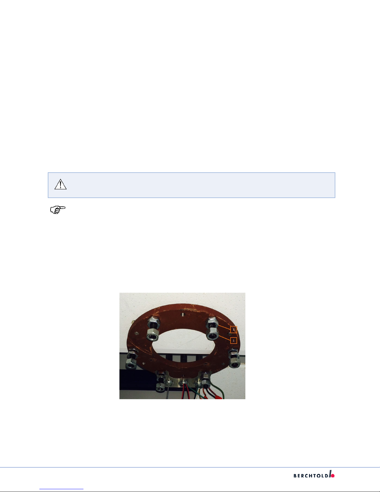
2. Unscrew all six securing nuts (1) with at washers from the ceiling anchor plate/ceiling ring/ceiling void
assembly. The adjusting nuts onthe ceiling side (2) remain on the threaded bolts.
3. Remove the ange tube.
4. Pass the ange of the ceiling tube over the six free threaded bolts of the ceiling anchor plate.
20
Page 26
S
Note: Ensure ceiling tube is level using a digital level.
5. Apply at washers and mounting nuts to three threaded bolts by hand, spaced at 120° intervals.
6. Align the ceiling tube vertically in the room using a level and the adjustment screws on the ceiling side.
7. Little by little, tighten the mounting nuts ensuring that the alignment of the ceiling tube is maintained.
8. Screw the mounting nuts with washers from step 1 onto the other three threaded bolts, and with
tighten torque to 34 N-m.
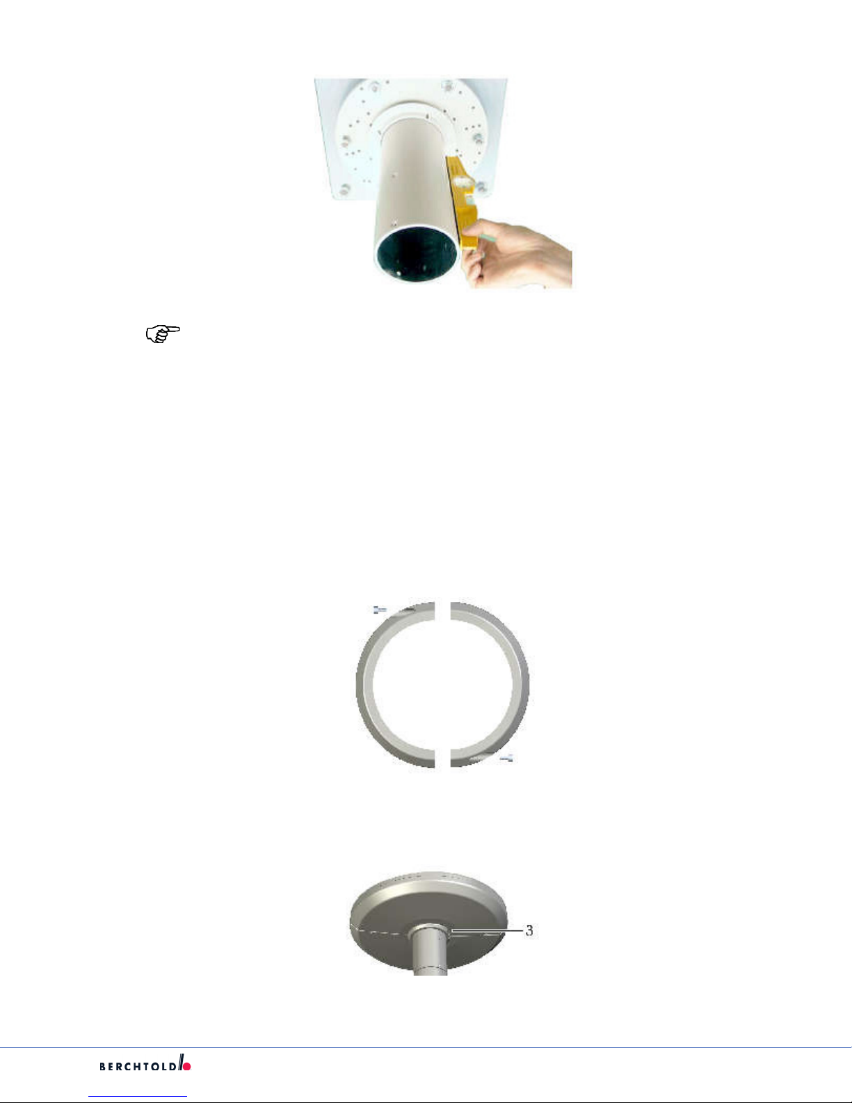
9. Attach both halves of the securing ring to the ceiling tube using a rubber gasket for ceiling cover.
10. Adjust the ceiling cover ush with the ceiling.
11. Screw the ceiling cover tight using the securing ring(3).
21
Page 27
S
7.3 Replacing a Suspension for Lights and Light/Flat Panel Combination
Suspensions
WARNING: Before performing the following steps, the electricity for the Lights and/or
Monitors has to be powered OFF.
Note: When replacing a Suspension with a Flat Panel Arm the cables shall be back pulled
from the doc station.
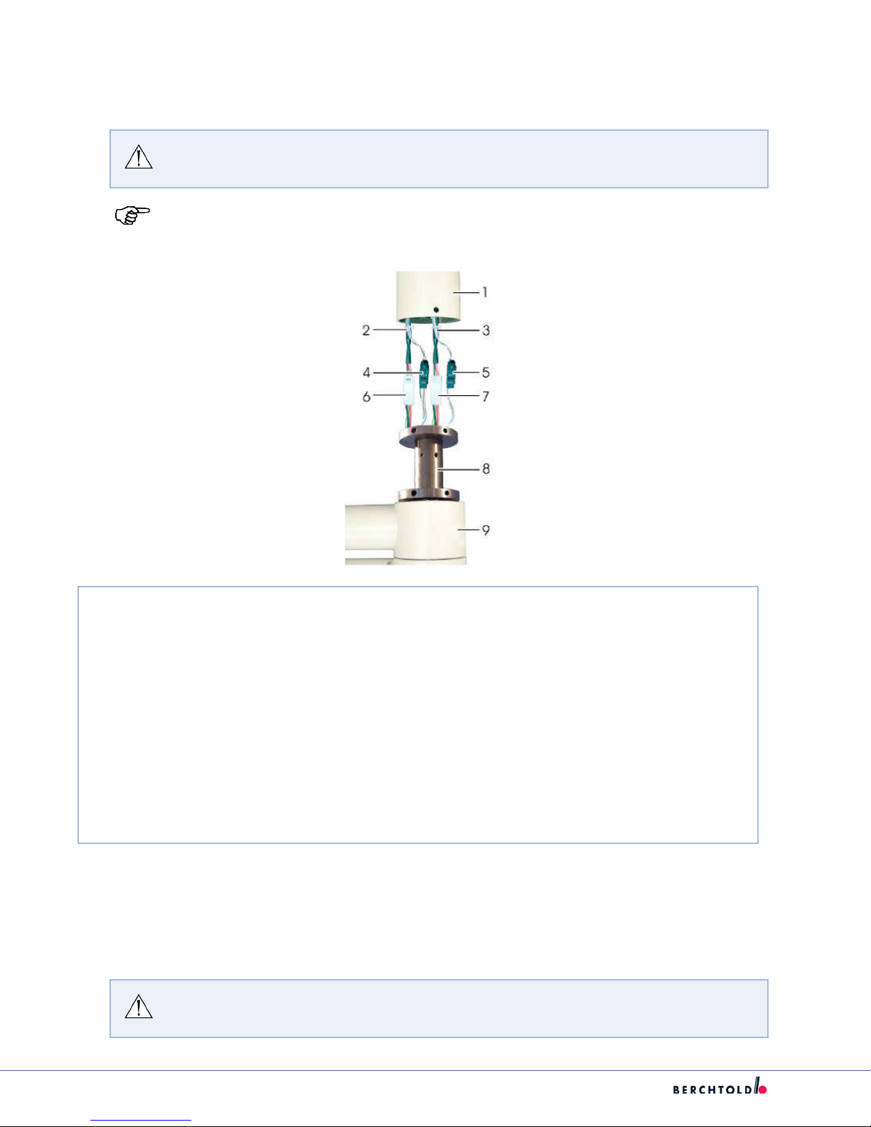
1
Ceiling Tube
2
Connection cable for light 1
3
Connection cable for light 2
4
4-pole connection plug for light 1, 4 poles used, 2-pole CAN bus (black/white)/2-pole
video(brown/white)
5
4-pole connection plug for light 2, 2 poles used, 2-pole CAN bus(black/white)/2-pole-video not
used
6
Light 1 connector, power supply
7
Light 2 connector, power supply
8
Central Bearing Shaft
9
Horizontal Arm
1. Remove Light Head or Monitor Yoke and Spring Arm as instructed in section 7.9.
2. Disconnect plug in connectors 4-7.
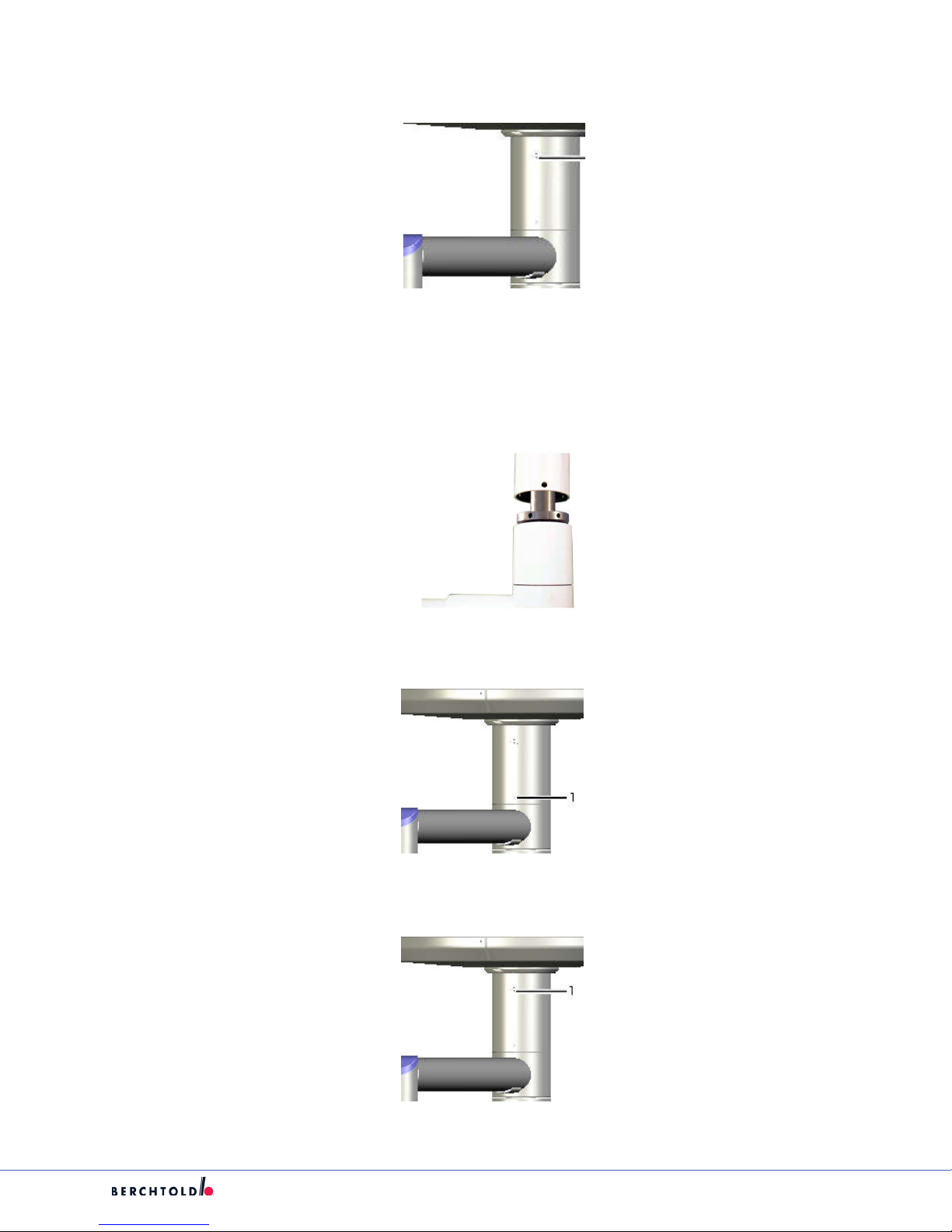
3. Remove the ve countersunk bolts with 5mm Allen wrench (1) leaving the shoulder screw attached.
WARNING: The suspension WILL fall if the safety screw is removed at this time. Ensure
suspension is secure on lift prior to proceeding to the next step.
22
Page 28
S
4. Remove the safety shoulder screw (1) and tighten to 5 N-m using 5mm hex key.
5. Lower arm and attach replacement arm to lift for installation.
6. Raise arm up to the ceiling tube and attach plug-in connectors 4-7.
7. Push the central bearing shaft into the ceiling tube. In so doing, make sure the mounting holes are lined
up with the holes in the ceiling tube.
8. Insert the safety shoulder screw(1) and tighten to 5 N-m using 5mm hex key.
9. Apply ve countersunk bolts with hexagonal sockets (1) into the remaining slots and tighten to 12 N-m
using a 5mm hex key.
23
Page 29
S
7.4. Replacing the Horizontal Arm on a Wall Single Light
WARNING: Before performing the following steps, the electricity for the Lights and/or
Monitors has to be powered OFF.
CAUTION: There is a risk of injury from spring-loaded joints. If the spring arm is
released under tension, it will move quickly and uncontrollably, possibly causing
injury or damage to equipment.
1. Hold onto the spring arm when installing or removing the light head.
2. Avoid putting pressure on the spring arm and releasing it suddenly.
3. Spring arm should always have the stop set for the spring arm to be parallel
1. Remove Light Head as instructed in section 7.9.
2. Remove Spring Arm as instructed in section 7.6.
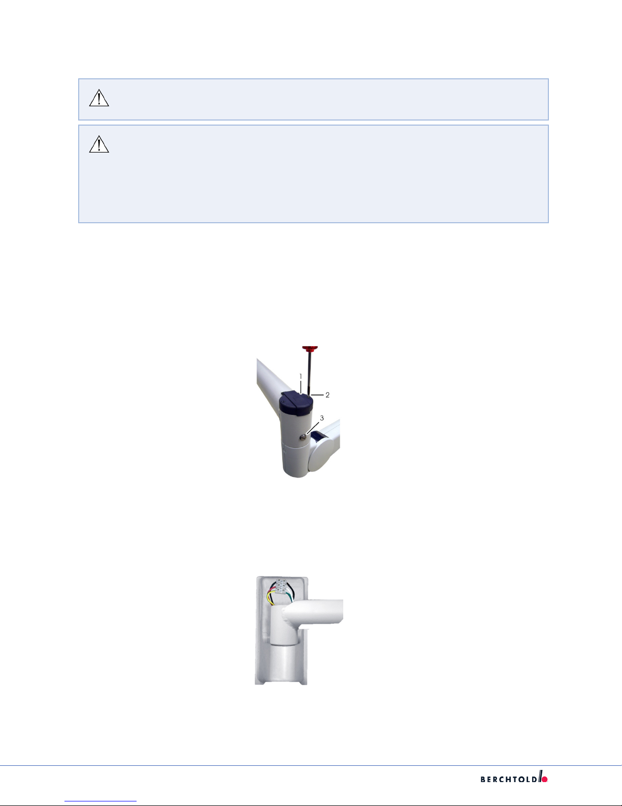
3. Loosen cap screws(2).
4. Remove the cover cap(1).
5. Remove Brake Screw(3).
6. Locate terminal block on the bearing journal.
7. Disconnect the cables from the terminal block.
8. Pull up squarely on Horizontal arm and remove (horizontal arm is held on by gravity).
9. Install new arm.
24
Page 30
10. Reconnect the cables to the terminal block.
Cantilever Wall bracket
green/yellow connect to green/yellow
white connect to red
black connect to black
11. Reinstall the cover cap (1).
12. Reinstall cap screws (2).
13. Install brake screw (3).
S
14. Install Spring Arm as instructed in section 7.6.
15. Install Light Head as instructed in section 7.9.
7.5. Replacing a Spring Arm for Light Head or Flat Panel Support Arm (Ceiling
Suspension)
WARNING: Before performing the following steps, the electricity for the Lights and/or
Monitors has to be powered OFF.
CAUTION: There is a risk of injury from spring-loaded joints. If the spring arm is
released under tension, it will move quickly and uncontrollably, possibly causing
injury or damage to equipment.
1. Hold onto the spring arm when installing or removing the light head.
2. Avoid putting pressure on the spring arm and releasing it suddenly.
3. Spring arm should always have the stop set for the spring arm to be parallel.
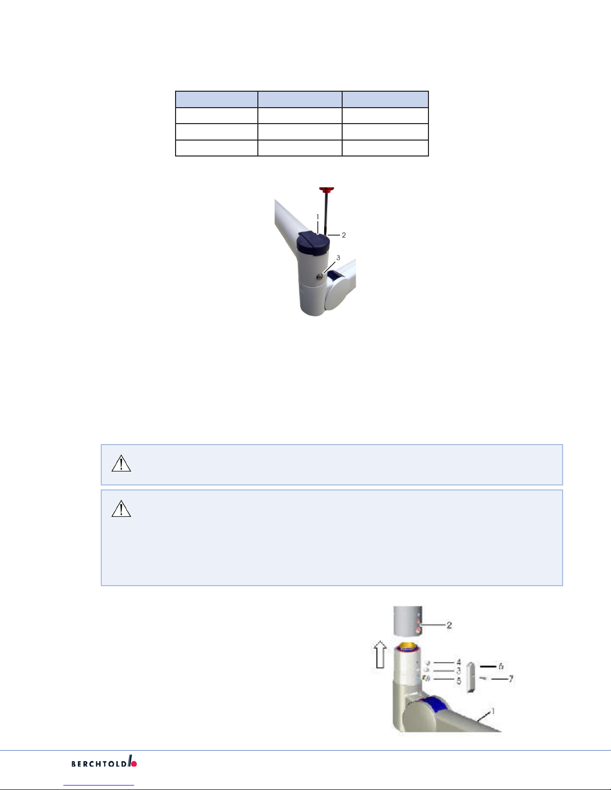
1. Remove the Light Head or Monitor Yoke as
instructed in section 7.9.
2. Remove the round-headed screw (7) from the
thread of the safety screw and cover (6).
3. Remove the brake screw (5), round screw (4),
and safety screw (3).
25
Page 31

S
WARNING: Before performing the following steps, the electricity for the Lights and/or
Monitors has to be powered OFF.
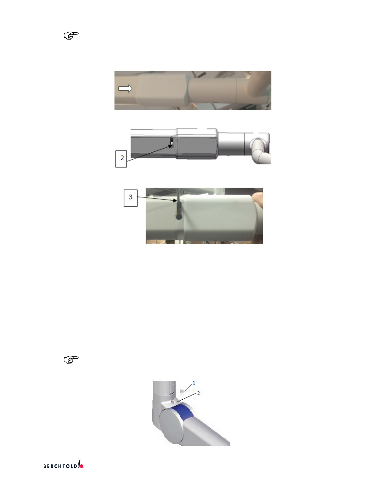
4. Remove the spring arm.
5. Insert the spring arm (1) into the horizontal arm (2) in the direction of the arrow.
Note: Ensure that the holes in the spring arm are lined up with the bore holes on the
horizontal arm.
For Light Head installation ensure that the contact pins line up and connector connects
securely.
Failure to plug in the contacts correctly may result in
permanently damaged or destroyed connectors.
6. Insert the safety screw (3) into the central bore hole and tighten to a torque of 4 N-m.
7. Insert round-headed screw (4) into the upper screw thread and tighten to a torque of 5 N-m.
8. Insert brake screw (5) far enough into the lower thread that the spring arm does not drift away
independently.
9. Install cover (6).
10. Screw a round-headed screw (7) into the thread of the safety screw (3).
11. Reinstall the Light Head or Monitor Yoke as instructed in 7.9.
26
Page 32
7.6. Replacing Spring Arm for Wall Mounted Single Light
WARNING: Before performing the following steps, the electricity for the Lights and/or
Monitors has to be powered OFF.
CAUTION: There is a risk of injury from spring-loaded joints. If the spring arm is
released under tension, it will move quickly and uncontrollably, possibly causing
injury or damage to equipment.
1. Hold onto the spring arm when installing or removing the light head.
2. Avoid putting pressure on the spring arm and releasing it suddenly.
3. Spring arm should always have the stop set for the spring arm to be parallel.
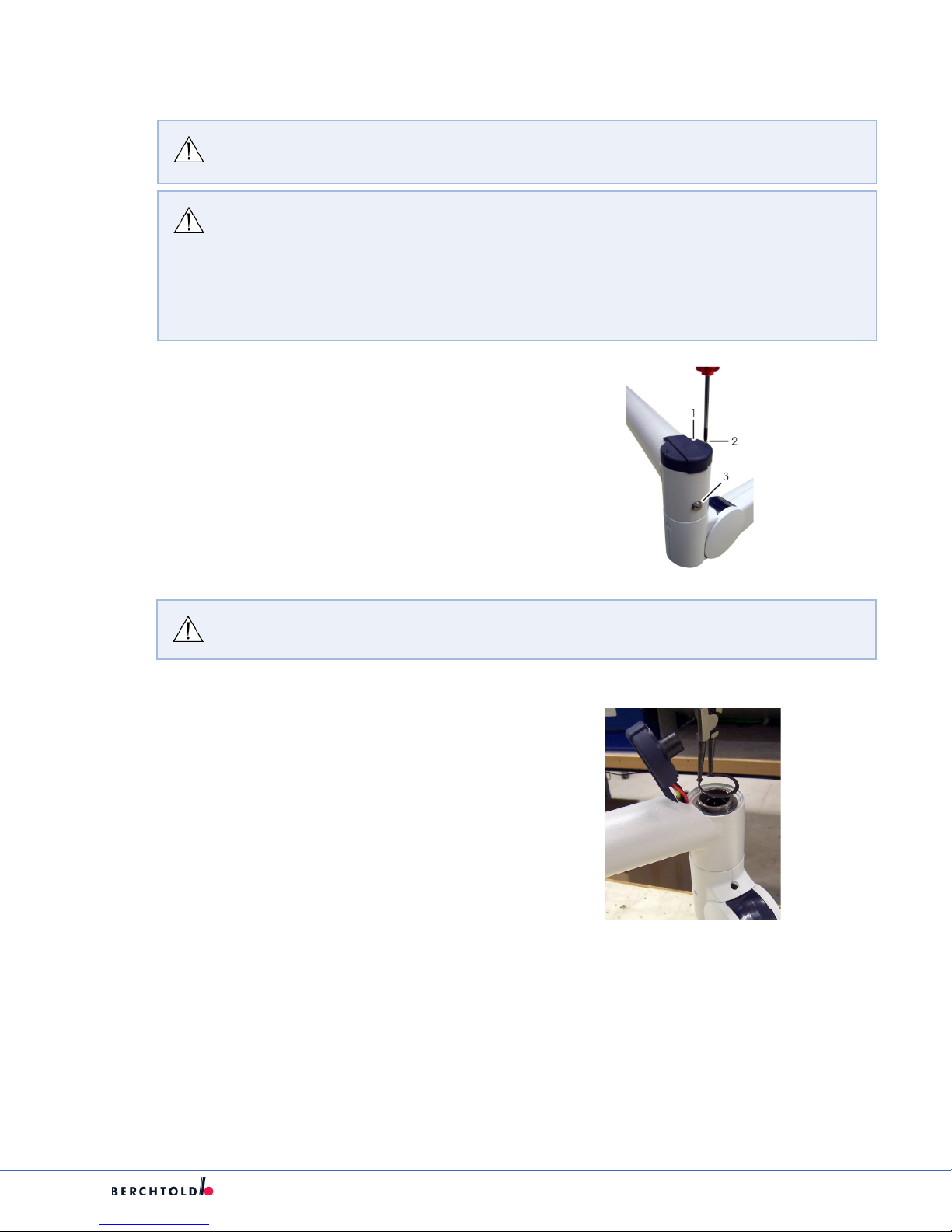
1. Remove the Light Head as instructed in
section 7.9. Remove the Brake Screw (3).
2. Remove Contact Holder (1) by removing the
two Philips screws (2).
S
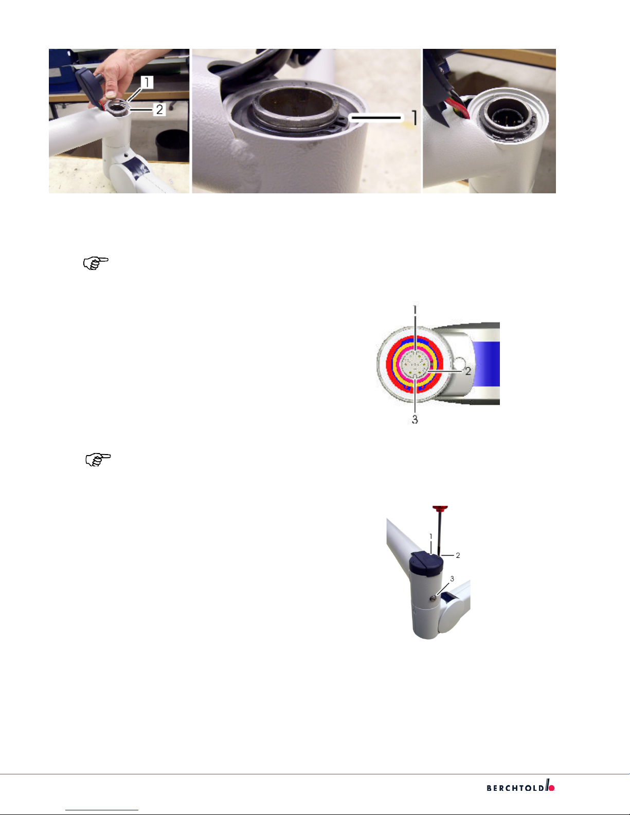
WARNING: The spring arm WILL fall once the two Circlips are Removed.
3. Remove the two Circlips using Circlip Pliers.
4. Remove Shim rings.
5. Remove the Spring Arm.
6. Push New Spring Arm onto the Horizontal
Arm.
7. Install Brake Screw.
8. Install the two Shim Rings removed above in
Step 5.
27
Page 33
S
9. Install two Circlips in the grooves (1) and ensure that the Ciirclips are completely snapped into their
corresponding groove.
Note: Ensure that the holes in the spring arm are lined up with the bore holes on the
horizontal arm.
10. Align the plug connector contacts.
11. Attach Contact Holder (1) by installing the two
Philips screws (2).
12. Adjust the brake screw (3) in order to achieve
the desired braking action.
Note: Failure to plug in the contacts correctly may result in permanently damaged or
destroyed connectors.
13. Reinstall the Light Head as instructed in section
7.9.
28
Page 34
7.7. Replacing Spring Arm for VPA
WARNING: Spring arm for VPA is a DEPOT Level Repair.
7.8. Replacing VPA POD
WARNING: VPA POD is a DEPOT Level Repair.
S
7.9. Replacing the Light Head or Monitor Yoke
WARNING: Before performing the following steps, the electricity for the Lights and/or
Monitors has to be powered OFF.
CAUTION: There is a risk of injury from spring-loaded joints. If the spring arm is
released under tension, it will move quickly and uncontrollably, possibly causing
injury or damage to equipment.
1. Hold onto the spring arm when installing or removing the light head.
2. Avoid putting pressure on the spring arm and releasing it suddenly.
3. Spring arm should always have the stop set for the spring arm to be parallel.
29
Page 35
S
7.9.1 Classic Cardanic for Light Head or Monitor Yoke
Note: When replacing the Monitor Yoke the cables shall be back pulled from the doc
station.
Note: The following steps apply to all E and F Series Light Heads being installed on a
Classic Spring Arm.
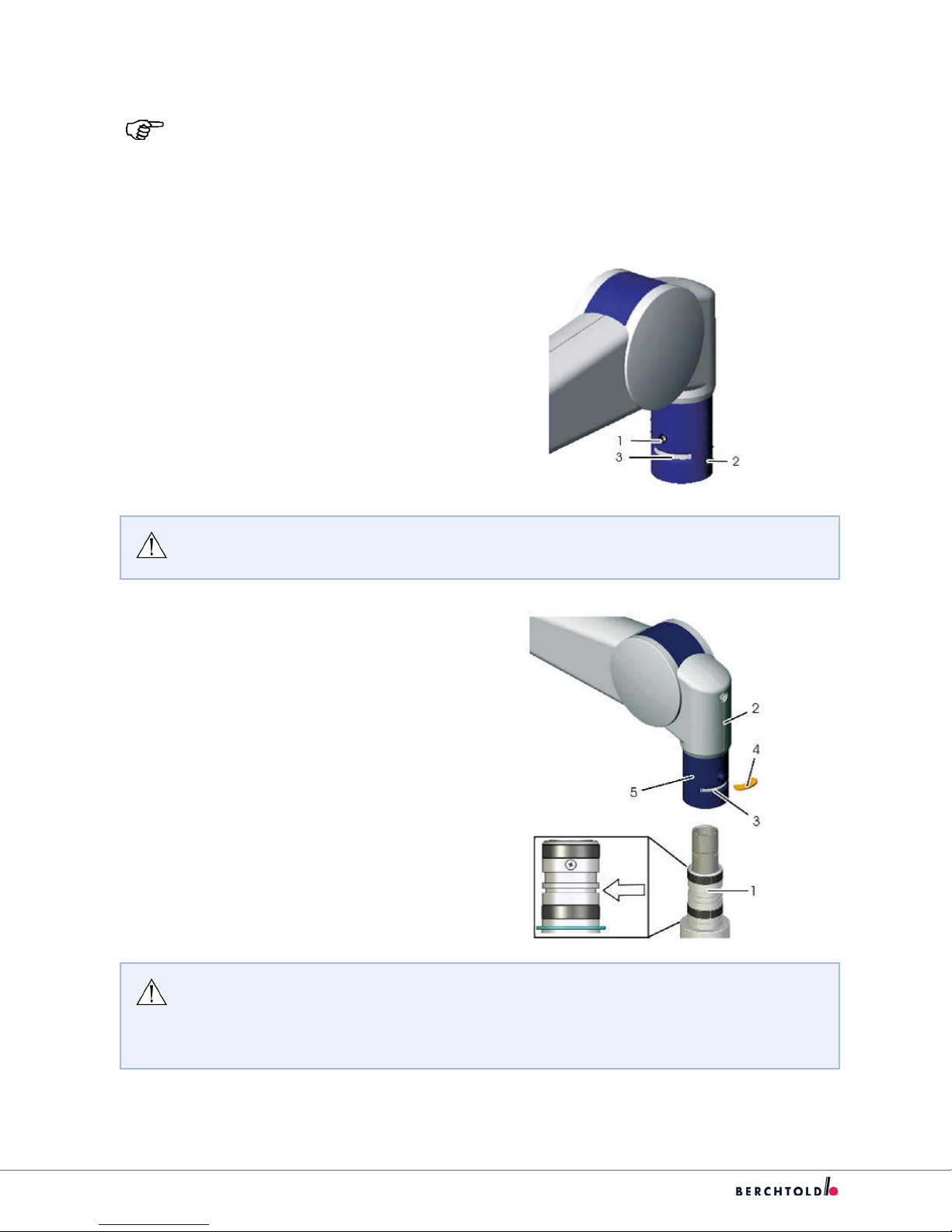
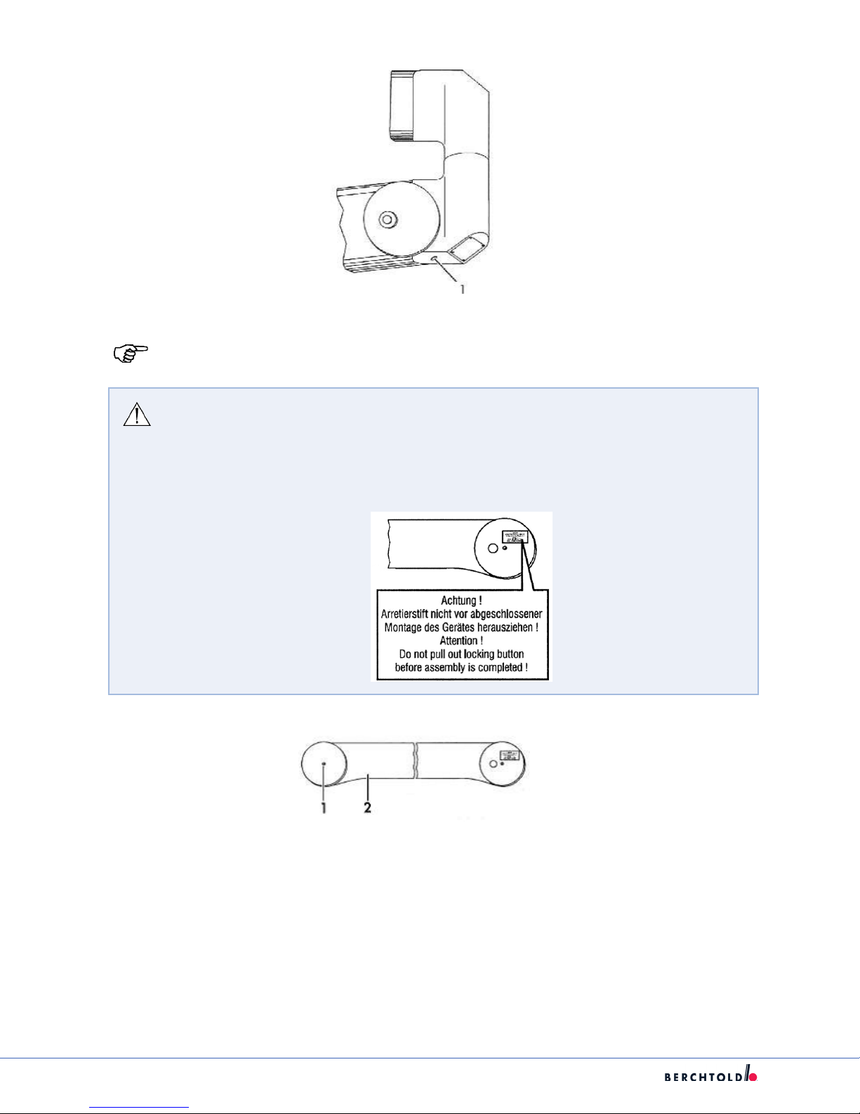
1. Remove screw (1) from the lock bushing.
2. Turn lock bushing 180° (2) exposing the locking
segment and the journal groove (3).
3. Remove the locking segment from the journal
groove (3).
WARNING: Before performing the following steps, the electricity for the Lights and/or
Monitors has to be powered OFF.
4. Remove the Light Head or Monitor Yoke.
5. With replacement Light Head or Monitor Yoke,
advance the journal of the light bow (1) into the
spring arm (2) until the journal groove(as seen
by the arrow) appears in slot 3.
6. Insert the locking segment (4) into the journal
groove (3).
7. Turn the lock bushing (5) 180° to lock the
locking segment in lace.
8. Insert the lock bushing screw (1) into the lock
bushing and tighten.
WARNING: Failure to install the locking segment WILL result in the Light Head or
Monitor Yoke falling.
Failure to secure the lock bushing with the screw may result in the locking segment
to disengage resulting in the Light Head or Monitor Yoke falling.
30
Page 36

7.9.2 Flat Cardanic
WARNING: Failure to install the locking segment WILL result in the Light Head or
Monitor Yoke falling.
Failure to secure the lock bushing with the screw may result in the locking segment
to disengage resulting in the Light Head or Monitor Yoke falling.
1. Remove the brake screw (1).
S
2. Turn the locking bushing (4) 180° exposing the shoulder screw (3).
3. Remove the shoulder screw (3).
4. Remove the Light Head.
5. With the replacement Light Head, align the contact pins inside the journal of the light bow.
31
Page 37

S
WARNING: Failure to plug in the contacts correctly may result in permanently
damaged or destroyed connectors.
6. Insert the journal of the light bow (1) until it reaches the spring arm (2).
7. Screw in the shoulder screw (3) in until the light head is just un-braked.
8. Turn the lock bushing (4) 180° securing the shoulder screw.
9. Install the brake screw (1) into the free thread.
10. Adjust the braking force with the brake screw as such that the Light Head is easy to move but remains
stationary in the desired position.
7.9.3 New Flat Cardanic (N.F.C)
WARNING: When installing brake screws on a NC or NFC springarm, screw it in until it
stops then back it out ¼ turn (90°). Check to see if the component is stable. Loosen or
tighten accordingly, but never back this screw out more than 1 turn (360°) to prevent
it from falling out inadvertently.
1. Remove at head brake screw (2).
2. Loosen the second allen head break screw but DO NOT remove.
3. Turn the locking bushing (3) 180° exposing the shoulder screw(1).
4. Remove the shoulder screw(1).
5. Install shipping lock to keep the spring arm at 90 degrees.
a. Slide the plastic sleeve forward and install the pin through arm.
b. Install circlip retainer.
32
Page 38

6. Remove the Light Head and Cardanic from the spring arm.
7. With the replacement Light Head, align the contact pins inside the journal of the light bow.
S
WARNING: Failure to plug in the contacts correctly may result in permanently
damaged or destroyed connectors.
8. Insert the Light Head Cardanic as far as it will go.
9. Install the shoulder screw (1) until the screw just touches the cardanic.
10. Turn the lock bushing (3) 180° securing the shoulder screw.
33
Page 39

S
11. Install the at head brake screw (2) into the free thread.
12. Remove the circlip retainer and the shipping lock.
13. Slide the plastic sleeve into the locked position.
14. Adjust the braking force with the brake screw as such that the Light Head is easy to move but
remains stationary in the desired position.
WARNING: Failure to properly install the shoulder screw and secure the lock bushing
with the break screw may result in the Light Head falling.
34
Page 40
S
7.10. Adjusting Suspension Brakes for Lights, Flat Panels, and VPA
WARNING: Failure to properly install the shoulder screw and secure the lock bushing
with the break screw may result in the Light Head falling.
Note: Turning the brake screw clockwise will increase the braking action and turning the
brake screw counterclockwise will decrease the braking action.
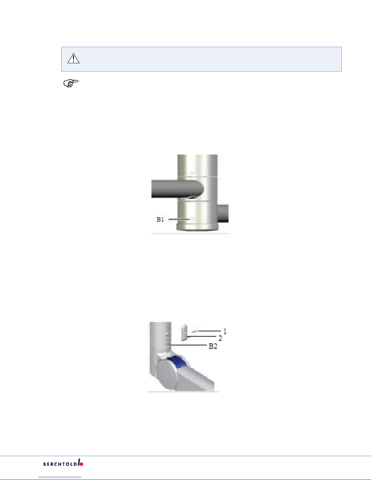
7.10.1 Horizontal Arm Brakes
1. Adjust the braking eect to suit the rotational movement of the horizontal arm using brake screw (B1).
7.10.2 Light/Flat Panel Spring Arm Brakes
1. Remove Screw (1) and the cover (2).
2. Adjust the braking eect to suit the rotational movement of the spring arm using brake screw (B2).
3. Re-attach the cover(2) with the screw (1).
35
Page 41

S
7.10.3 Cardanic Brakes on a Classic
1. Adjust the braking eect on the cardanic joint using brake screw (B3)
7.10.4 Cardanic Brakes on the Flat Cardanic
1. Adjust the braking eect to suit the cardanic joint using brake screw (B4)
7.10.5 Cardanic Brakes on New Flat Cardanic
1. Adjust the braking eect to suit the cardanic joint using brake screw (B5)
36
Page 42
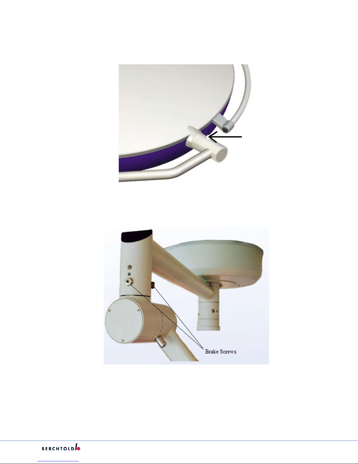
7.10.6 Light Head Brakes
1. Adjust the braking eect to suit the rotational movement of the Light Head.
S
7.10.7 VPA Spring Arm Brakes
1. Adjust the braking eect to suit the rotational movement of the horizontal arm using brake screws.
37
Page 43

S
7.11. Adjustments for Lights, Flat Panel, and VPA Suspensions
7.11.1 Spring Arm Height Adjustment for Lights and Flat Panel Spring Arms
1. Remove the covering cap using a small screwdriver. The height adjustment screw for the height stop is
beneath the cover cap (HB).
2. Put the spring arm in the horizontal position.
3. Adjust the height limitation using the adjustment screw (HB).
4. Re-attach the covering cap.
Note: Turning the height screw in the clockwise direction reduces the height and in a
counter clockwise direction increases the height.
7.11.2 Flat Cardanic Height Adjustment
1. Remove the casing shell (1).
2. Pull o the casing shell (1) in the direction of the arrow.
3. Rotate the casing shell (1) downwards as shown.
4. Bring the spring arm to a position whereby the hole nuts (2) are visible in the slot.
5. With a steel pin or equivalent (3) rotate the whole nut until the desired height limitation is achieved.
6. Re-attach the casing shell (1).
38
Page 44
Note: Turning the height screw in the clockwise direction reduces the height and in a
counter clockwise direction increases the height.
7.11.3 Height Adjustment for NFC Spring Arms
1. Slide the plastic sleeve forward; exposing the adjustment slot.
2. Bring the spring arm to a position whereby the adjustment nut (2) is visible in the slot.
S
3. With a steel pin or equivalent (3) rotate the adjustment nut until the desired height limitation is
achieved.
7.11.4 Counter Balancing the Spring Arm for Lights and Flat Panels
1. Remove the cover cap(1) using a small screw driver. Adjustment screw for counterbalancing is beneath
the cover cap.
2. Put the spring arm into the closest position to be parallel with the oor.
3. Adjust the spring arm tension using the adjustment screw (2).
Note: Turning the height screw in the clockwise direction reduces the height and in a
counter clockwise direction increases the height.
39
Page 45

S
7.11.5 VPA Spring Arm Up/Down Brakes
1. The vertical movement of the spring assist arm can be adjusted by increasing or decreasing the brake
screws applied to the brake.
2. First remove the (3) cover plate screws and remove the cover plate.
3. For proper spring assist arm movement, the (4) brake screws will require equal torque.
4. Turn screws clockwise if arm is pulling upward.
5. Turn screws counterclockwise if it is dicult to move arm.
6. Make adjustments to the brake screws until best results are achieved.
7. Replace cover plate and re-fasten the (3) cover plate screws.
40
Page 46

S
7.11.6 VPA Height Stop Detents
1. The Detent System will maintain vertical position of the spring arm at 20 degree increments; a total
movement of 60 degrees. The Ball Spring Plunger should be fastened with Loctite applied to threads
and inserted completely to function properly.
Note: The Detent Stops are not adjustable.
7.12 Spring Arm Wire Harness Replacement for Lights
CAUTION: There is a risk of injury from spring-loaded joints. If the spring arm is
released under tension, it will move quickly and uncontrollably, possibly causing
injury or damage to equipment.
1. Hold onto the spring arm when installing or removing the light head.
2. Avoid putting pressure on the spring arm and releasing it suddenly.
3. Spring arm should always have the stop set for the spring arm to be parallel
1. Remove light from spring arm and place on a working surface; remove the spring arm from the
suspension place on a solid at working surface.
2. Remove the bearing housing and spring arm covers.
41
Page 47

S
3. Remove the screw holding harness connectors in the spring arm (both front and back). Cut wire set and
remove.
4. Tape pins and end of wires together to keep them protected during assembly.
5. Pull wire set thru spring arm and install female 7 pole connector in front part of arm, install screw by
tighten fully then back of ¼ turn.
42
Page 48

6. Pin out female connector as follows:
Note: Standard Pinout for 7-Pole Spring Arms.
S
1) Rose Can-buss high
2) Grey Can-buss low
3) Yellow Y (camera)
4) Brown C (camera)
5) PE Green/Yellow Gnd
6) L black 1 + 24vdc
7) Ctr Black 2 - 24vdc
7. Install the screw holding harness connector in the spring arm back part.
43
Page 49

S
8. Install bearing housing, inspect bearings for proper movement.
9. Install washer over bearings.
10. Install snap ring check for proper operation.
11. Install spring arm and test light as per class requirements.
44
Page 50
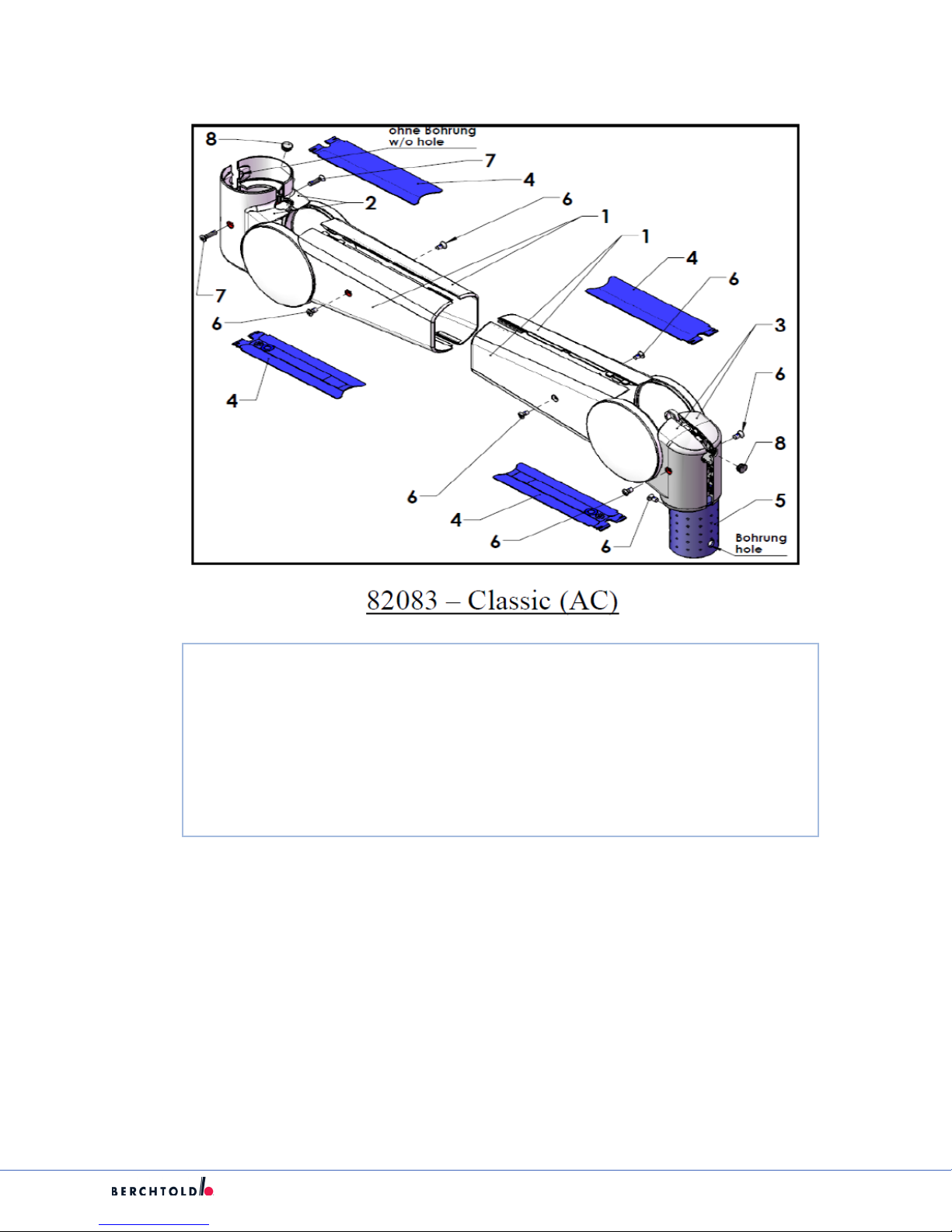
7.13 Spring Arm Cover Replacement
S
1 79999 Side cover 1 & 2
2 79998 Back Elbow Cover 1 & 2
3 79997 Spring Arm Joint Cover 1 & 2
4 80657 Blue Tab
5 74191 Safety Sleeve
6 77235 Countersunk Screw w/Tuock, M4X8-A2, Din 966
7 80664 Countersunk Screw Raised Head, M4X16-A2, Din 966
8 N/A N/A
45
Page 51

S
1 79999 Side cover 1 & 2
2 79998 Back Elbow Cover 1 & 2
3 80657 Blue Tab
4 74182 Spring Arm Cover
5 80664 Countersunk Screw Raised Head, M4X16-A2, Din 966
6 226 Screw, ISO 7047-H M3X0.5X6. CR-OHMS, SS
7 77235 Countersunk Screw w/Tuock, M4X8-A2, Din 966
8 N/A N/A
46
Page 52

S
1 84398 Front Spring Arm Cover
2 79998 Back Elbow Cover 1 & 2
3 79999 Side cover 1 & 2
4 80664 Countersunk Screw Raised Head, M4X16-A2, Din 966
5 77235 Countersunk Screw w/Tuock, M4X8-A2, Din 966
6 80657 Blue Tab
7 N/A N/A
7.15 Dual Flat Panel Arm Maintenance
Note: Only congure the height-adjustment of the Dual Flat Panel Spring Arm after a
successful weight counterbalance.
7.15.1 Dual Flat Panel Spring Arm Counterweight Adjustment
1. Insert a 6mm allen wrench into the adjustment opening (1).
2. Bring the Dual Flat Panel Spring Arm into the closest position to be parallel with the oor.
3. Adjust the spring arm tension using the adjustment screw (1).
Note: Turning the tension screw in the counter clockwise direction increases tension and
in the a clockwise direction decreases the tension.
47
Page 53
S
7.15.2 Dual Flat Panel Spring Arm Height Adjustment
Note: The Dual Flat Panel Arm is congured to have a height-adjustment of 40° upwards
and downwards when delivered. The height stop can be set to 20°.
WARNING: The Dual Flat Panel Spring Arm is under a high level of tension. The arm
can move uncontrolled and may result in injuries.
DO NOT set the retaining pin until assembly is complete.
1. Unscrew the Philips-head screws (1) and remove the casing halves (2).
2. Loosen retaining pin (3).
3. Remove the retaining ring (6) with the spreader forceps.
4. Removed the stop pin (7) from the “40°” boreholes.
5. Insert the stop pin into the bore holes at “20°”
6. Secure the stop pin with the retaining ring (6). Ensure the correct positioning of the retaining ring.
48
Page 54

7. Bring the spring arm to its highest position.
8. Apply the 147mm cover strap on the rear hinge, in the lower channel.
9. Apply the 130mm cover strap on the front hinge, in the upper channel.
10. Bring the spring arm to its lowest position.
11. Apply the 130mm cover strap on the rear hinge, in the upper channel.
12. Apply the 130mm cover strap on the front hinge, in the lower channel.
S
13. Ensure that the cover straps lie completely within the channels.
14. Screw on both casing halves using Philips-head screws. Ensure the secure positioning of the casing
halves.
7.15.3 Adjusting the Monitor Bracket, Version II
1. Adjust the side elements to the at screen bracket (1) to suit the width of the screen. To do so use the
scale (2) on the cross-beam.
49
Page 55

S
7.15.4 Adjusting the Brakes
WARNING: Risk of injury if braking action of joint fails. If the brake screws are
lubricated or residual lubrication is left on them, they lose their braking action and
the articulated joints will not stop as desired when moved.
Note: Turning the brake screw in the clockwise direction increases the braking eect and
turning in and anticlockwise direction reduces the braking eect.
7.15.5 Brakes, Cross Connector, Versions I and II
1. Adjust the braking eect to suit the rotational movement of the Dual Flat Panel Arm using brake screw
(B7)
7.15.6 Brakes, Monitor Suspension, Version I (rotary movement)
1. Adjust the braking eect to suit the rotational movement of the Dual Flat Panel Arm using brake screw
(B4)
7.15.7 Brakes, Monitor Suspension, Version I (tilt movement)
1. Adjust the braking eect to suit the rotational movement of the Dual Flat Panel Arm using brake screw
(B5)
50
Page 56

S
7.15.8 Brakes, Monitor Suspension, Version I (tilt movement)
1. Adjust the braking eect to suit the rotational movement of the Dual Flat Panel Arm using brake screw
(B1).
7.15.9 Brakes, monitor Suspension, Version II (tilt movement)
1. Adjust the braking eect to suit the rotational movement of the Dual Flat Panel Arm using brake screw
(B3).
7.16 Servicing Suspension Stop Rotation
7.16.1.1 Changing/Replacing Stop Location
Note: If the Suspension internal stop is broken, perform steps 2 through 7. If the
Suspension External stop is broken, perform steps 2 and 8.
1. Turn the horizontal arm (1) to the rotation stop.
2. Unscrew the external stop screw (2) with a 6mm allen wrench.
51
Page 57

S
3. Continue to turn the horizontal arm until the internal stop screw (3) is visible.
4. Unscrew the internal stop screw.
Note: If the internal Suspension stop is broken, a removal tool may be needed to remove
the broken screw.
5. Turn the horizontal arm to the desired position.
6. Screw in the unscrewed stop into the appropriate, visible thread (4) and torque to 30 N-m.
7. Continue to turn the horizontal arm until the internal stop screw is no longer visible.
8. Screw in the external stop screw (5) once again.
52
Page 58

S
7.17 Horizontal Arm Maintenance
WARNING: Before performing the following steps, the electricity for the Lights and/or
Monitors has to be powered OFF.
7.17.1 Replacing Height Compensation Tube (HCT) on Horizontal Arm
The HCT is a vertical down tube, available in varying lengths, used to put the spring arms are in an equal
horizontal plane.
Note: When replacing height compensation tube with Flat Panel arm, the Cables shall be
back pulled from the doc station.
1. Remove Light Head or Monitor Yoke per section 7.9.
2. Remove the Spring Arm per section 7.5.
3. Remove plastic cover (1) with round-headed screw (2).
4. Remove the special washer (2) with the round-headed screw (3) from the upper screw thread.
5. Remove the round-headed screw (1) from the upper screw thread.
6. Remove the height Compensation tube from the horizontal arm.
53
Page 59

S
7. Insert the height Compensation tube into the horizontal arm. In so doing, make sure that the holes of
the height Compensation tube line up with the holding holes in the horizontal arm.
8. Insert the round-headed screw (1) into the upper screw thread and tighten to 5 N-m.
9. Insert a special washer (2) with the round-headed screw (3) into the upper screw thread and tighten to 5
N-m.
10. Secure plastic cover (1) with round-headed screw (2).
11. Reinstall Spring Arm per section 7.5.
12. Reinstall Light Head or Monitor Yoke per section 7.9.
54
Page 60
S
7.17.2 Replacing internal wiring on Horizontal Arm (light suspension only)
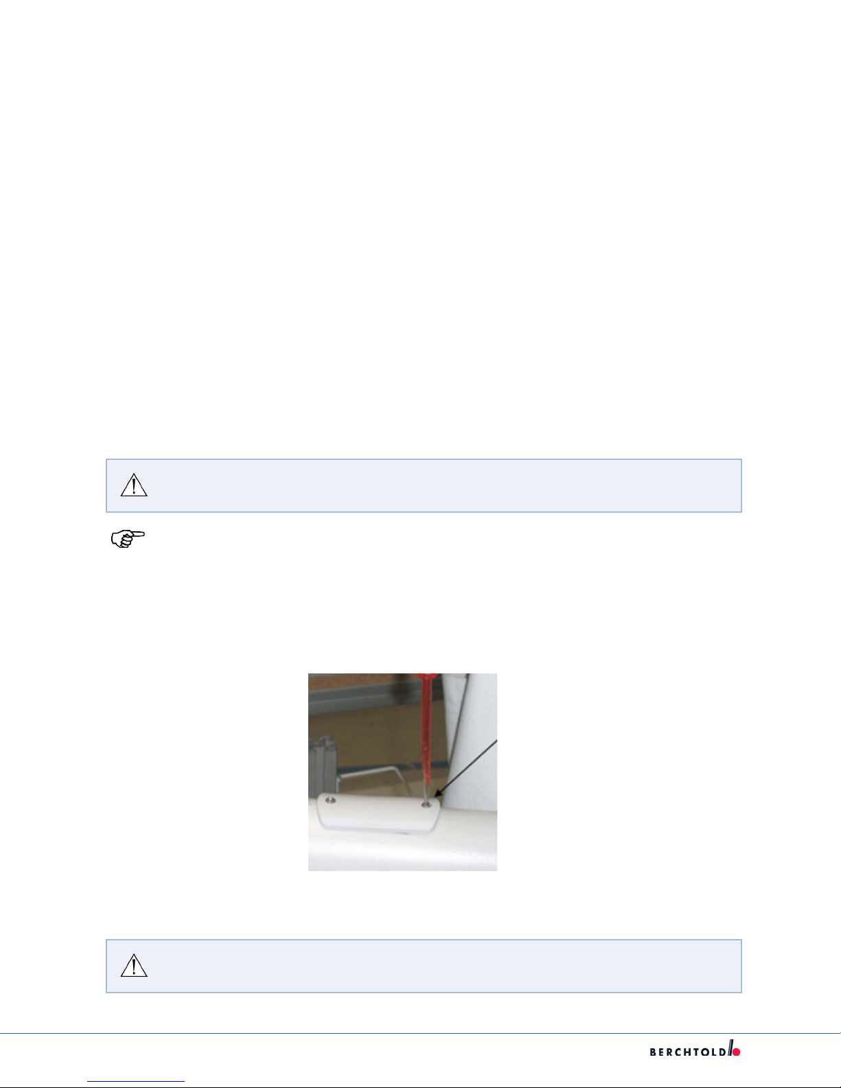
1. Secure power to the system from the circuit breaker.
2. Remove Light Head from Spring Arm per section 7.9.
3. Remove Spring Arm per section 7.5.
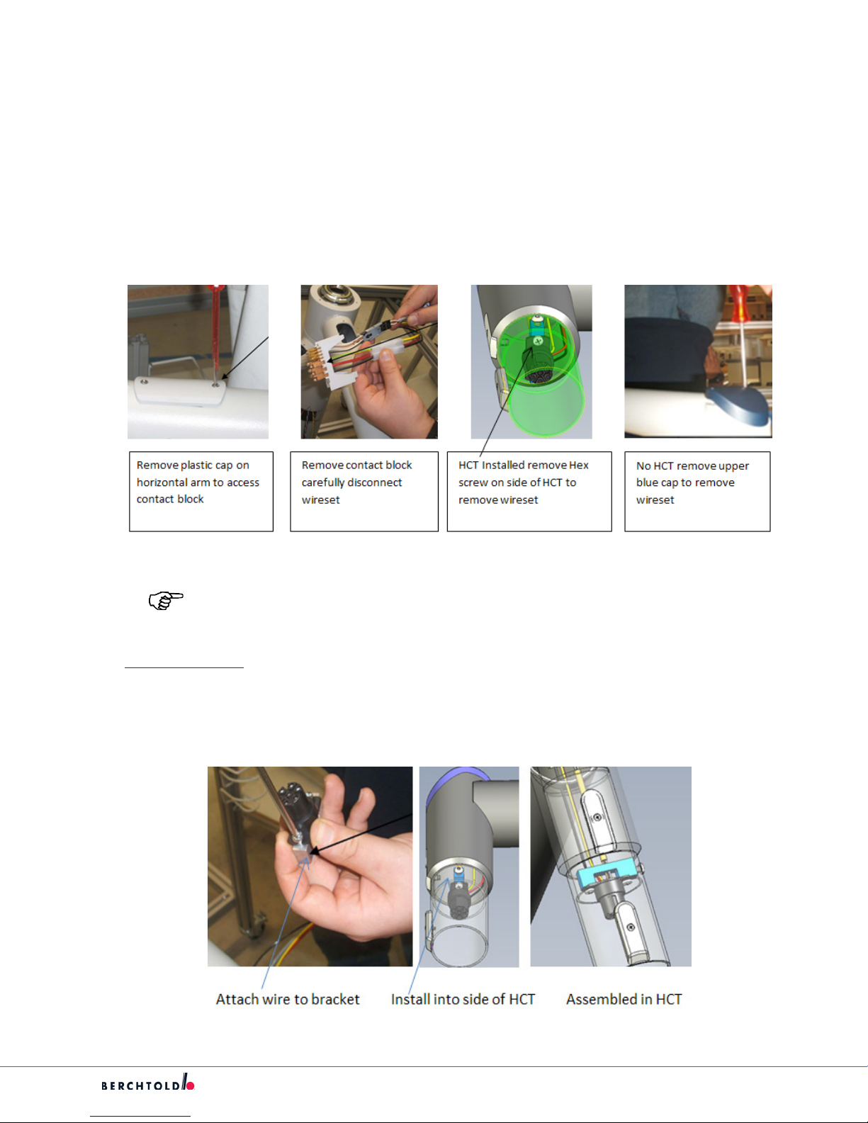
4. Remove 2 cross head screws on the bottom of the horizontal arm next to the central shaft to access the
contact block.
5. Carefully remove contact block with the wire set attached. Disconnect wireset from contact block.
Note: Contact block is fragile and can be damaged if care is not observed.
6. For units with HCT
a. Remove the 5mm hex screw on the side of the HCT,
b. Remove wireset and bracket from the arm.
c. Disconnect wireset from bracket by removing the 2 4mm screws.
d. Attach new wireset to bracket using the 2 screws removed.
55
Chromophare suspension wiring with HCT
Page 61
S
e. Run wires thru the HCT down the horizontal arm and out the access of the contact block.
f. Replace the 5mm hex screw on the side of the HCT and tighten.
g. Proceed to step 8.
7. For units with no HCT
a. Remove upper front blue cover by removing the 2 3mm screws.
b. Pull the cover up and carefully remove the wireset from the arm.
c. Disconnect the wireset from bracket by removing 2 Torx Ejot screws.
d. Attach new wireset to bracket using the 2 screws removed.
e. Run wires thru the horizontal arm and out the access of the contact block.
f. Replace the upper front blue cover by reinstalling the 2 3mm screws and tighten.
8. Attach wireset to contact block and tape the 4 pin connector to ensure it does not disconnect.
9. Place the contact block into the suspension and verify that all prongs are touching the slip ring(see
above)
10. Place the plastic cover into place, making sure that the connection end of the cover snaps into place on
the contact block.
CAUTION: If the cover is not snapped into place correctly, the suspension will not
function properly.
11. Replace the 2 cross head screws and tighten.
12. Reinstall Spring Arm per section 7.5.
13. Reinstall Light Head per section 7.9.
14. Restore power and check the system for proper operation.
56
Page 62

S
7.18 Replacing Suspension Bottom Cap (Jar Cover)
1. If replacement of the bottom suspension cap (Jar cover) becomes necessary, obtain a replacement kit
(pn 107120).
2. Verify that the 3 screws are present in the cap as shown.
3. If applicable, remove the existing cover from the bottom of the suspension.
4. Align the 3 screws with the corresponding holes in the bottom of the suspension. Push the cover into
place.
CAUTION: All 3 screws must be fully tightened to ensure complete thread
engagement into the suspension arm. Failure to do this could allow the cover to
become inadvertently separated from the suspension arm.
5. Using a phillips-head screwdriver, attach the cap to the suspension. Tighten the screws until they
are fully engaged against the washers that are molded into the cap.
57
Page 63

S
7.19 Suspension Mounted EndoLite
7.19.1 General Information
The ENDO light is an accessory option that mounts to the Chromophare suspension. It is mounted to the
central bearing shaft assembly attached to the bottom of a horizontal arm. It provides background light
when the full light of a surgical light is not needed.
There are two (2) variants of the suspension mounted Chromophare ENDO light. The rst is for suspensions
with a surgical light mounted on the bottom arm of the suspension. With this unit, the power and CAN bus
are received from the output of the contact block mounted on the bottom arm of the suspension thru a
transition cover (Figure 1).
The second variant is used when there is a non-powered bottom arm (single/dual at panel) on the
suspension. With this unit, the power and CAN bus are received from a wireset brought down from the
top of the suspension thru the center of the shaft (Figure 2). Both units are functionally the same and are
energized from the controller using the ENDO selection.
58
Page 64

S
59
Page 65

S
60
Page 66

S
7.19.2 Endo Repair
WARNING: Disconnect all power supplies before removing the EndoLite assembly.
Failure to do so will result in damage to the circuit board.
1. Determine if the issue is circuit board related or cable connection issue by verifying all connections and
checking voltages. All circuit boards are interchangeable between units.
2. Remove transition cover on lower arm and check to ensure there is 24vdc going to the ENDO circuit
from the contact block, if voltage is present and ENDO is not working the board/s will have to be
replaced.
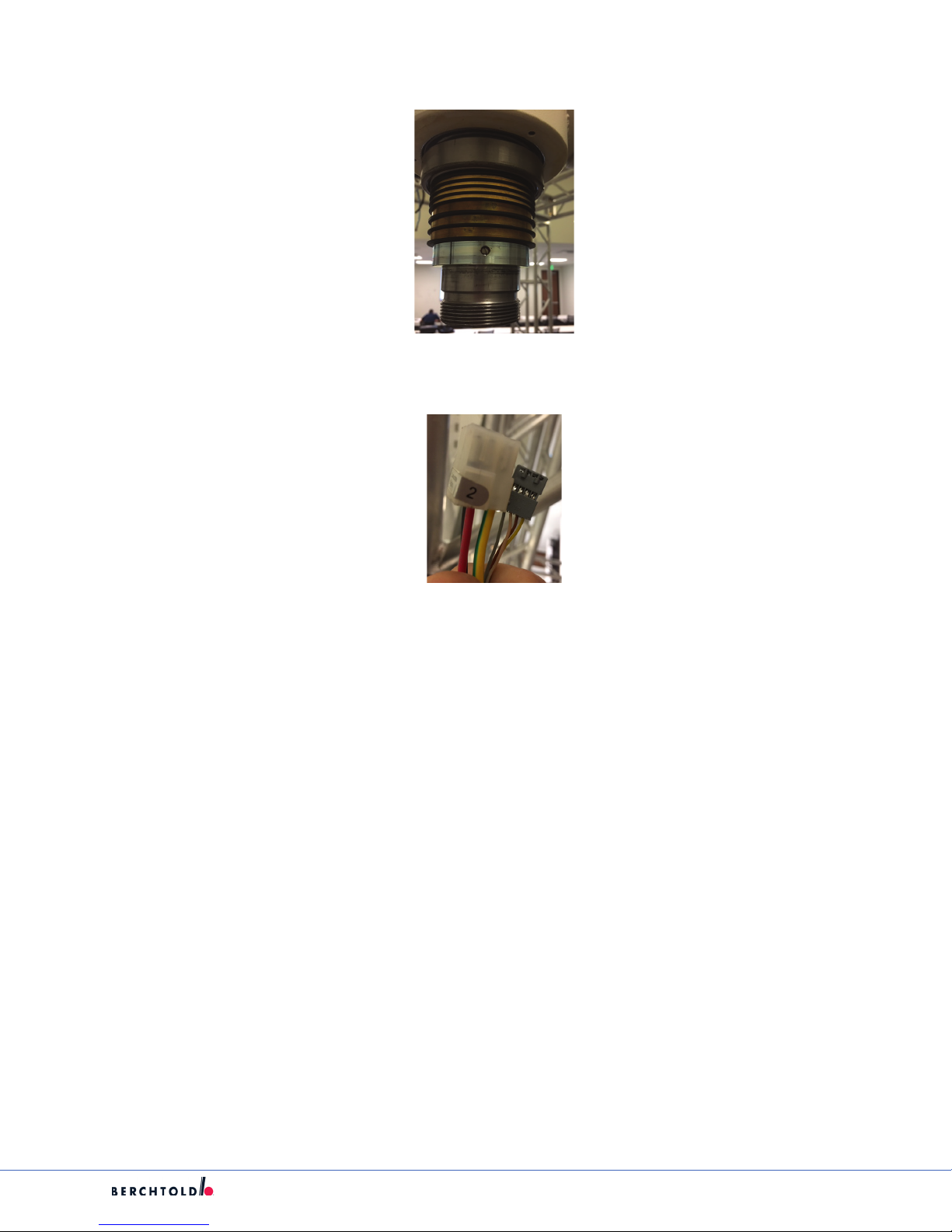
3. Remove sot cover locate Endo light cable set and check to ensure there is 24vdc going to the ENDO
circuit, if voltage is present and ENDO is not working the board/s will have to be replaced.
4. If voltage(24vdc) was present, secure power and proceed with replacing driver and led boards.
5. Access the Circuit boards by removing the 3 screws, from the bumper. Remove the rubber safety
bumper by pulling down gently; remove 3 screws and washers holding ENDO LED assembly to the plate
Piece 2.
6. Remove lower cap assembly slowly until cable is exposed; disconnect power/control cable 4 pin Molex
connector see (Figure3/4) from the Driver board, set assembly aside for rework. The assembly includes
circuit boards (2), window, reector, bottom cap.
Figure 3 wireset to driver board, 4 pin Molex light on
bottom
Note: Both LED units have identical circuit boards .
61
Figure 4 single/dual at panel bottom arm mounted on
the bottom to driver board, 4 pin Molex light on bottom
Page 67
S
7. To remove Driver PCB circuit board, piece 6, remove three (3) screws and pull up gently to unseat the 8
pin socket connected to the LED circuit board, remove and place aside Driver board. To remove the LED
Circuit board, Piece 7, remove the 3, 10mm standos.
8. Replace bad LED Circuit board and reinstall the 3 standos are installed thru the reector and tighten.
Line up 8 pin socket and pins and reinstall Driver PCB, replace the 3 screws, and tighten. Select the
same color on the driver board as the color taken o, either Green or White.
9. Reassemble assembly taking care to ensure the window and the gasket are correctly in place, seen in
Figures 1 and 2.
10. Reinstall assembly onto suspension, slowly place the lower cap assembly onto the suspension lower arm
until power/control cable 4 pin Molex can be reconnected to the Driver PCB, seen in gures (Figure 3/4).
Replace 3 screws and washers and tighten.
11. Reinstall bumper Piece 5 with the 3 screws removed.
12. Restore power and check for proper operation.
7.20 Replacing the Slip Ring (Commutator) on an F Gen Light
WARNING: Make sure that the Lights are powered o prior to performing service.
Note: If it is suspected that the slip ring is damaged, make sure that the issue is not due to
a damaged wire set or contact block before completing this repair (see Step 3).
1. Remove the light head or monitor yokes as instructed in Section 7.9.
2. Remove the spring arm as instructed in Section 7.6.
3. Remove the two Phillips screw on the bottom of the horizontal arm next to the central shaft to access
the contact block.
4. Carefully remove the contact block with the wire set attached. Disconnect the wire set from the contact
block.
CAUTION: Use extreme care when handling the contact block, as it is very fragile.
62
Page 68

5. Remove the three screws from the Endo light or jar cover and set them aside.
WARNING: To prevent electrocution and burns, make sure the power to the light
system is turned o.
S
6. If you have an Endo light:
a. Unplug the 4 pin molex connector.
b. Remove the three screws from the internal plate and pull the plate away.
c. Disconnect the cable.
7. If the suspension has more than one arm, use an equipment lift to support the other extension arms.
WARNING: To prevent injury or damage, do not proceed unless multi-arms are
supported by an equipment lift.
8. Use the castlenut driver to remove the jammer nut.
63
Page 69

S
9. Remove the c-clip with the correct c-clip pliers.
10. Use a #6 Allen wrench to remove the brake screw of the extension arm.
11. Use a rubber mallet or your hand and tap down on the top of the extension arm to remove the central
axis.
64
Page 70
S
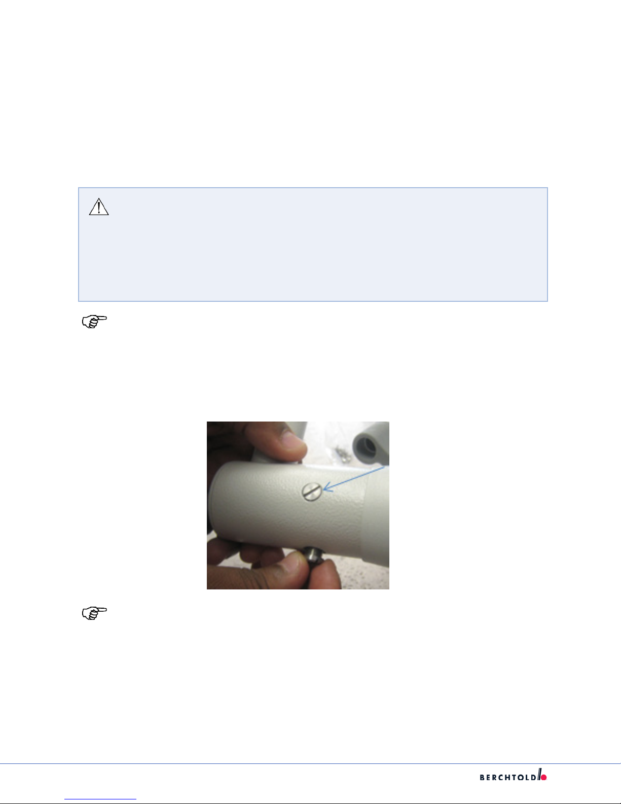
12. Remove the set screw from inside the slip ring (Commutator).
13. Disconnect the cabling for the slip ring at the ceiling. Cut o the end of the connectors and pull the
cabling down and out of the system.
14. Remove the slip ring.
15. Slide a new slip ring onto the system and feed the wiring through the system in the same way as it was
before.
16. Install the set screw. If the old set screw is damaged, use the new one included with the repair kit.
17. Use the connectors from the kit and re-terminate the cabling at the tip of the ceiling.
18. Slide the central axis up over the slip ring and install the brake screw.
a. Reinstall the c-clip.
b. Reinstall the jammer nut.
c. Reinstall the plate and Endolight light or jar cover. If reinstalling the Endolight, make sure to
reconnect the molex connector.
19. Reinstall the spring arm according to Section 7.5.
20. Reinstall the light head according to Section 7.9
21. Turn on the power and check the system to make sure it operates correctly.
65
Page 71

S
8. Cardanics
WARNING: Ensure Lights are powered o prior to performing service.
8.1 Cardanic Replacement
8.1.1 Cardanic Replacement for EXX0/EXX5 Light Heads (Halogen/HID)
CAUTION There is a risk of injury from spring-loaded joints. If the spring arm is
released under tension, it will move quickly and uncontrollably, possibly causing
injury or damage to equipment.
1. Hold onto the spring arm when installing or removing the light head.
2. Avoid putting pressure on the spring arm and releasing it suddenly.
3. Spring arm should always have the stop set for the spring arm to be parallel
with the oor when servicing.
Note: This procedure applies to Classic, Flat, and NFC Cardanic replacement.
1. Remove Light from Spring Arm and place on a working surface.
2. Remove the at head brake screw (2) and retainer screw (1).
Note: There are 3 at head screws on the Cardanic to light xation, two brakes and one
retainer all must be removed.
3. Remove light dome using gasket removal tool set to allow access to wire sets.
4. Disconnect input power, can-bus, ribbon cable and camera wire set (if installed).
66
Page 72

S
5. Remove the Cardanic from the light body by gently rotating back and forth while pulling cardanic away
from light body.
6. When cardanic is o pull wire sets out of the light body ensuring all connectors are protected.
7. With the replacement Cardanic, sh wire sets thru side of the light body, then align the cardanic bow
onto the light body journal and install cardanic by gently rotating back and forth while pushing cardanic
onto the light body journal.
8. Install brake screws and retainer removed in step 2.
9. Attach wire sets to correct locations as removed.
67
Page 73
S
10. Install dome onto Light Head ensuring gasket is not damaged.
11. Install Light Head on to Spring Arm.
12. Adjust brakes in order to achieve the desired braking action.
13. Complete operational check of Light, Cardanic and Spring Arm.
8.1.2 Cardanic Replacement for EXX8 Light Heads (E LED)
CAUTION There is a risk of injury from spring-loaded joints. If the spring arm is
released under tension, it will move quickly and uncontrollably, possibly causing
injury or damage to equipment.
1. Hold onto the spring arm when installing or removing the light head.
2. Avoid putting pressure on the spring arm and releasing it suddenly.
3. Spring arm should always have the stop set for the spring arm to be parallel
with the oor when servicing.
Note: This procedure applies to Classic, Flat, and NFC Cardanic replacement.
1. Remove light from spring arm and place on a working surface.
2. Remove the at head brake screw (2) and retainer screw (1).
Note: There are 3 at head screws on the Cardanic to light xation, two brakes and one
retainer all must be removed.
68
Page 74

3. Remove screws holding in the focus mechanism plastic ring in place.
4. Remove LED face glass using gasket removal tool set to allow access to wire sets.
S
5. Remove the four screws holding the tube in place.
69
Page 75

S
6. Disconnect wiring red and black 24vdc and 4 pin Molex can/camera and ground from inside of cardanic.
7. Remove the Cardanic from the light body by gently rotating back and forth while pulling cardanic away
from light body.
8. When cardanic is o pull wire sets out of the light body ensuring all connectors are protected.
9. With the replacement Cardanic, sh the wires thru side of the light body, then align the cardanic bow
onto the light body journal and install cardanic by gently rotating back and forth while pushing cardanic
onto the light body journal.
10. Install brake screws and retainer removed in step 2.
11. Attach wire sets to correct locations as removed.
70
Page 76

12. Reinstall tube using the four screws removed in earlier step.
13. Install Led face glass using gasket tool.
14. Install plastic ring for focus mechanism.
15. Install light head on to spring arm.
16. Adjust brakes in order to achieve the desired braking action.
17. Complete operational check of light, cardanic and spring arm.
8.1.3 Cardanic Replacement for FXX8 Light Heads (F-Gen)
CAUTION There is a risk of injury from spring-loaded joints. If the spring arm is
released under tension, it will move quickly and uncontrollably, possibly causing
injury or damage to equipment.
1. Hold onto the spring arm when installing or removing the light head.
2. Avoid putting pressure on the spring arm and releasing it suddenly.
3. Spring arm should always have the stop set for the spring arm to be parallel
with the oor when servicing.
S
Note: F Generation lights have a newly designed cardanic. To change or replace the
cardanic will require the removal and reinstallation of an internal blind single snap
ring. This requires a special tool shown below. This tool is only for use by factory trained
service technicians.
8.1.4 F-Generation Cardanic Security Tool:
F-Gen Complete Tool:
F-Gen Tool with 1-1 on the left and 1-2 on the right:
1. Remove Light from Spring Arm and place on a working Surface.
71
Page 77

S
2. Remove the joint cover and 7-pole rotating connector from the end of the cardanic.
3. Utilizing outer straight tipped slip ring pliers; remove Internal Blind Snap Ring.
4. Remove the two spring washers 83222 from the cardanic.
5. Remove the cardanic from the light head.
Note: Step 6 is only for Variants 83469, 83470, and 83289. Step 7 is for only Variants
83471 and 83472.
6. Attach the connector 77612 to the cover 83232 with (1) 83253 EJOT PT screw.
72
Page 78

7. Screw the 83273 coupling for the light control with the connector 77612 with (1) 83523 screw.
S
8. Slide cardanic onto the side bearing.
9. Secure the safety screw 83217.
10. Secure the brake screw 83264.
73
Page 79

S
WARNING: The following steps are critical to the security of the cardanic to the
Light Head.
11. Place two spring washers 83222 into the back of the interior joint.
12. Place the snap ring 83224 onto the tool “FGEN 1-1”.
13. Slide the snap ring up the tool until it nears the end.
74
Page 80

S
14. Slide the tool “FGEN 1-2” up to make contact with the snap ring. Ensure that the snap ring is oriented as
shown.
WARNING: Wiring can be damaged. Be careful when inserting the xture into the
joint.
15. Align the tool to allowing guiding of the wiring along the slot as shown.
16. Fully seat the tool into the joint. Ensure that the cardanic is seated ush with the side bearing.
17. With the palm of the hand, deliver a moderate blow to the tool to seat the snap ring onto the side
bearing.
18. Remove the tool from the joint area. It should disengage freely. Visually verify the snap ring is lodged
symmetrically.
WARNING: The snap ring MUST be fully engaged. Failure to ensure it is fully seated
may result in the Light falling.
19. Ensure instructions for proper Variant are being followed.
Note: Skip to Steps 20-21 for Variant 83468(AC Cardanic, Cover Only) and Variant 83289
(NC/NFC Cardanic, Cover Only)
Skip to Steps 22-25 for Variants 83468(AC Cardanic, Cover with 7-Pole)
Skip to Steps 26-32 for Variant 83469(AC Cardanic Control from Light Head Keypad
Skip to Steps 33- for Variant 83471(NC or NFC Cardanic Control from Light Head Keypad)
20. Tuck the cables into the cardanic joint area.
75
Page 81

S
21. Attach the cover 83467 to the middle joint and secure with the two screws 223.
Note: Steps 22-25 for Variants 83468(AC Cardanic, Cover with 7-Pole).
22. Tuck the connector cable back into the cardanic joint area.
23. Ensure that the 7-pole rotating connector is aligned so that it mates with the plug.
76
Page 82

24. Insert the plug and seat into the connector.
25. Secure the connector cap with (4) 64662 screws.
S
Note: Steps 22-25 for Variants 83468(AC Cardanic, Cover with 7-Pole).
26. Put wiring through the housing.
27. Secure the housing with (3) 87200 screws, (3) 378 washers, and (3) 1229 washers.
77
Page 83

S
28. Plug in the programmed light control set.
29. Tuck the wiring for the control pad into the cardanic.
30. Ensure the blue ribbon cable is not caught during the connection.
31. Secure the front cover to the housing.
32. Secure (1) 67589 screw into the rear of the assembly.
78
Page 84

Note: Steps 22-25 for Variants 83468(AC Cardanic, Cover with 7-Pole).
33. Pull the cable through the coupling 83273 as shown.
S
34. Ensure that the 7-pole rotating connector is aligned so that it mates with the plug.
35. Insert the plug and seat into the connector.
36. Secure the coupling with (4) 64662 screws.
37. Screw the housing 83287 into the cardanic coupling using (4) 84486 screws.
79
Page 85

S
38. Plug in the programmed light control set.
39. Tuck the wiring for the control pad into the cardanic.
80
Page 86
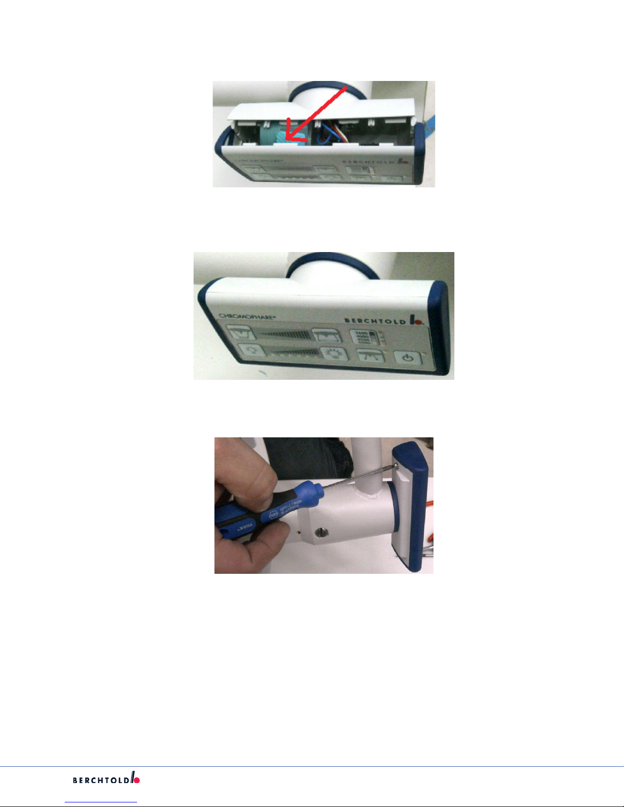
40. Ensure the blue ribbon cable is not caught during the connection.
41. Secure the front cover to the housing.
S
42. Secure (1) 67589 screw into the rear of the assembly.
81
Page 87

S
9. Light Head Maintenance
9.1 Light Handles / Focus Mechanism
Chromophare E 558, E 668, E 778, F 528, F 628 Light Handle Assembly (LED)
1. Handle 2. Sleeve
Chromophare E 655, E 805 Light Handle / Focus Mechanism Assembly (HID)
1. Handle 2. Sleeve
Chromophare E 550, E 650 Light Handle / Focus Mechanism Assembly (Halogen)
1. Handle 2. Sleeve
82
Page 88

9.1.1 Light Handle Replacement
Note: For HID and Halogen lights, the handle has glass bulbs on the distal end. Use
caution not to damage bulbs during removal and installation
S
1. Position the light head so that the face glass is facing upwards.
2. If present, remove the sterilizable handle from the handle (1).
3. Loosen the three thumbscrews located at the base of the Handle (2).
4. Pull the Handle assembly directly away from the Light Head to remove (3).
Note: For HID and Halogen lights, the handle has glass bulbs on the distal end. Use
caution not to damage bulbs during removal and installation.
5. To install, center the Handle (3) on Light Head and line up thumbscrew locations. Ensure the D-sub
connector is also aligned.
6. Install Light Handle (3) and tighten thumbscrews (2).
7. Check the light for proper operation.
9.2 F 528/628 (F-Gen) Light Head Maintenance
Note: With the exception of the light handle assembly, all repairs to the F-generation
light heads must be performed at the factory repair facility. Contact Technical Support to
arrange a loaner or replacement light head.
83
Page 89
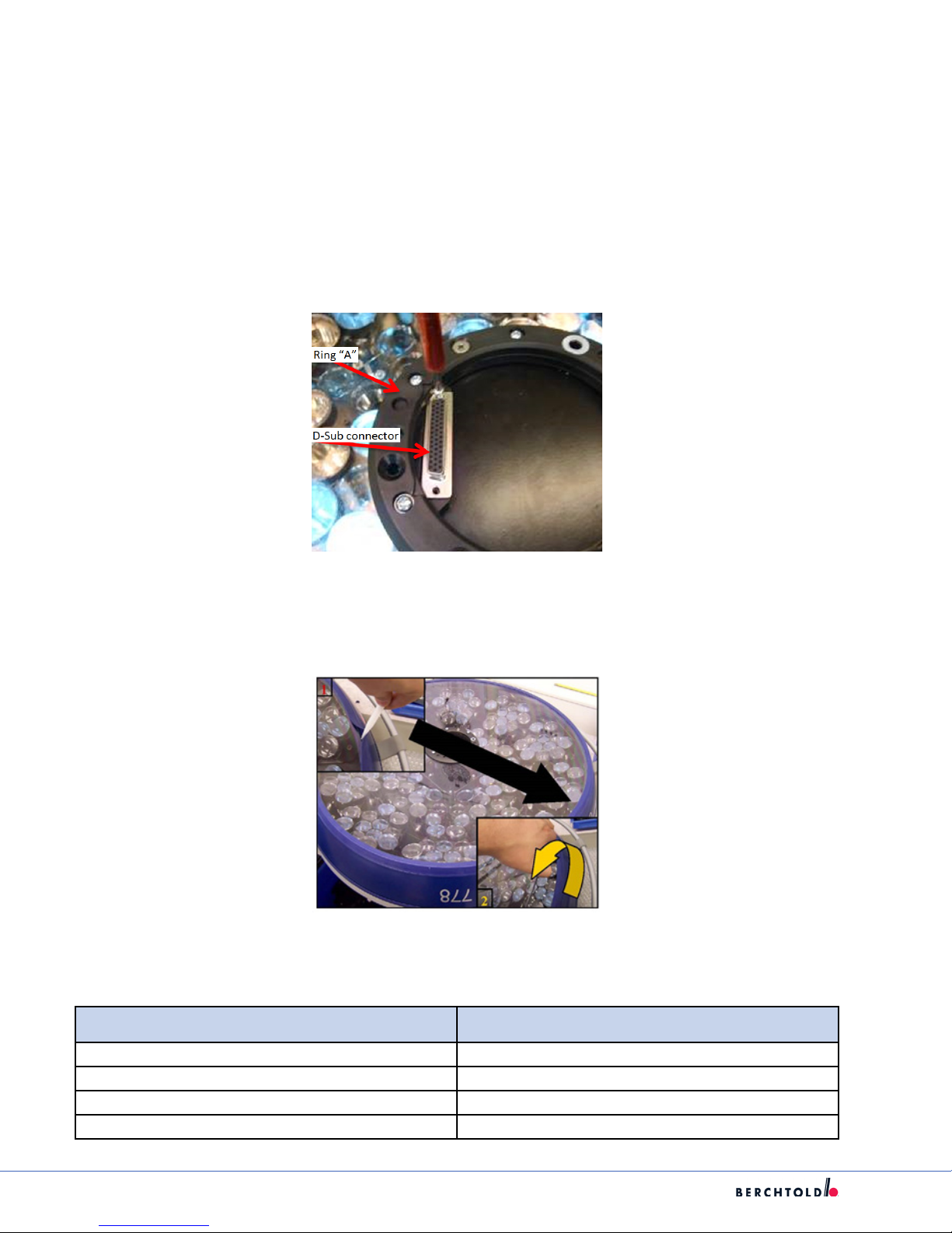
S
9.3 E558/668/778 (E LED) Light Head Maintenance
9.3.1 Accessing the light head internals
1. Remove the light head from the spring arm per section 7.9 and place it on a clean dry surface with the
glass facing up.
2. Remove focus handle assembly and place in safe place.
3. Remove the 2 Screws for D-Sub connector and remove from outer black ring (Ring A).
Ring “A” and Light Handle (D-Sub) Connector
4. Loosen and remove the 6 screws and remove ring A.
5. Release glass from gasket using gasket removal tool.
6. Carefully set the glass aside.
7. Refer to the appropriate section below for the corresponding internal component(s) needing service:
Section Component /Procedure
9.3.2 Lower Glass Replacement
9.3.3 Frame, Frame seal and/or glass seal
9.3.4 Distribution Board
9.3.5 LED Module(s)
84
Page 90

S
9.3.2 Lower Glass Replacement
1. Remove protective lm from new outer glass.
2. Proceed to section 9.3.6 to reassemble the light head.
9.3.3 Frame/Frame Seal/Glass Seal Replacement
1. Loosen but do not remove the retaining screws on xing plates and slide them toward the center of the
light head for removal of the frame and seal gasket.
Fixing plates Slide the plates towards the center to allow removal of
85
the frame and seal gasket
Page 91

S
2. Carefully remove damaged frame or gaskets being replaced
3. Install frame to dome gasket onto frame.
4. Ensure prole is fully engaged then place frame onto dome center.
5. Place xing plates onto side of frame in a crisscross pattern. Tighten each one only slightly (Do not
tighten fully on this step).
6. Once frame is centered tighten all screws in a crisscross pattern until lower gasket is secure.
7. Install frame to glass gasket onto frame ensuring gasket is fully engaged onto frame.
8. Proceed to section 9.3.6 to reassemble the light head.
86
Page 92

S
9.3.4 Distribution Board
The distribution board sends power to the LEDs and directs the Can-bus communications to and from each
module location.
Distribution board showing connection points
1. To access the distribution board, remove the 4 screws holding the center housing in place.
2. Lift the center housing and the D-Sub connector up and disconnect the D sub connector from the
distribution board.
3. Note and record the position of all the wiring on the distribution board. Remove all remaining
connectors.
87
Page 93

S
Module wiring locations on distribution board
4. Remove the 5 screws (4 corners and 1 in the center) holding the distribution board in place and lift the
distribution board out of the light head.
5. Place the new board with the same orientation and secure with the 5 screws removed in step 4 above.
Note: Grounding screw.
88
Page 94

S
6. Replace all of the connectors removed in step 3. Ensure all connections are rmly seated.
7. While holding the center housing assembly above the distribution board, replace the D-Sub connectors
removed in step 2. Ensure all connections are rmly seated.
8. Secure the center housing assembly with the 4 screws removed in step 1.
9. Refer to section 9.3.6 to reassemble the light head.
9.3.5 LED Module replacement
Failure of individual LEDs does not necessarily require module replacement. Measurements utilizing lux
calibrating cameras have shown that multiple single LEDs can fail within one or more modules with no
noticeable eect on the light eld.
E 778 - Up to 5 single LEDs may fail; either 5 in one module or one in 5 dierent modules (or any
combination) per the truth table below. When the 6th single LED fails, modules must be replaced until the
truth table is satised.
E558/E668 - Up to 2 single LEDs may fail; either 2 in one module or 1 in 2 dierent modules. When the 3rd
single LED fails, modules must be replaced to satisfy the truth table (below).
GREEN Light eld not aected. No module replacement required.
YELLOW Light eld minimally aected. Module replacement required.
RED Light eld adversely aected. Module replacement required.
CAUTION: If the LED Modules are replaced incorrectly by an unqualied
technician, signicant damage may result to the Light Head.
89
Page 95

S
WARNING: Secure power to the lighting system prior to completing the steps
below.
1. Remove bad module by removing the three perimeter screws and loosening the center post screw.
Module Fastener locations
2. Pull out the LED module and disconnect the two plugs on the LED control boards.
3. On the new module set the 6 DIP switch settings to match the module being removed.
90
Page 96

4. Connect the 2 plugs to the new module as before.
5. Place the new module routing the wiring underneath using the same path as previously used.
6. Install the perimeter screws and the center post screw.
S
7. Proceed to section 9.3.6 to reassemble the light head.
9.3.6 Light Head Reassembly (Refer to 9.3.1 for Illustrations)
1. Inspect the inside of the light head to insure there is not debris. If necessary, clean the LED modules with
a clean, lint-free cloth.
2. Inspect the lower glass for cleanliness. If necessary clean glass with a lint-free cloth prior to installation.
3. Place glass on the outside of the gasket, using gasket tool gently work the glass into the gasket without
damaging gasket.
4. Reinstall ring A using 6 the screws removed do not tighten in this step, rmly push down on the face
glass when re-attaching the screws.
5. Reinstall the D-Sub connector into ring A using the 2 screws removed insure sub D connector is aligned
to the hood access hole.
91
Page 97

S
6. Tighten all screws on Ring A and install focus handle.
7. Clean face glass prior to installing light.
8. Reinstall the light head onto the spring arm per section 7.9.
9. Restore power to the system. Insure all modules illuminate and that all controls operate properly.
9.4 E550/650 (Halogen) and E655/805 (HID) Light Head Maintenance
HID Technology – E805/E655
HID Primary bulb
BRITe Halogen Backup bulb
BRITe Technology – E650/E550
BRITe Halogen Primary bulb
BRITe Halogen Backup bulb
9.4.1 Dome Removal and Replacement Exx0/Exx5
1. Secure power at circuit breaker prior to proceeding.
2. Using gasket removal tool gently insert at side of tool under gasket and pry the dome up far enough to
get the tool under the dome. Gently rotate the light frame while moving the tool until the dome is able
to be extracted from the gasket.
3. If EndoLite option is installed (see section 9.4.2), disconnect the EndoLite socket wiring from the CPU
board connector J8.
4. Remove the dome assembly. If gasket is to be replaced, remove the old gasket now.
92
Page 98

S
5. To install the dome:
(a) Fit new gasket onto edge of frame (if needed), making sure the gasket is not stretched. To keep the
gasket from stretching, push back on the gasket every 3-4 inches until the complete unit is installed.
(b) If present, connect the EndoLite wiring back to CPU connector J8.
(c) Place the dome on top of the light and t into gasket on one side of the light.
(d) Place pressure on the side of the dome pulling toward the portion that is in the gasket.
(e) Slide the gasket tool under the side of the gasket and work around until gasket is sealed on the
entire dome.
9.4.2 EndoLite
The EndoLite is an optional 20 watt halogen light mounted to the center of the dome on E HID and Halogen
series lights.
93
Page 99

S
Parts List
1 64696 – Endo Bracke
2 64698 – Endo Cover Ring
3 66437 – Pivot for Endo Dome (Rivnut)
4 232 – M4 x 0.7 x 8 screw
5 64771 – Endo Socket
6 59833 – Endo Bulb 12V/20W
7 33 - Washer
8 39409 – M2.5 x 45 screw
9 62408 – Silicone Gasket
10 EndoLite label
1. The replace the bulb:
a) Remove the two fasteners (4), the cover ring (2) and the gasket (9).
b) Pull gently up on the bulb (6) to dislodge.
c) Install new bulb into socket (5).
d) Install the two fasteners (4), the cover ring (2) and the gasket (9).
2. To replace the socket assembly:
a) Remove the dome per section 9.4.1.
b) Remove the two screws (8) and washers (7) from the Endo bracket (1). Remove the socket
assembly (5).
c) Attach the new socket assembly with the same washers and screws.
d) Reinstall the dome per section 9.4.1.
9.4.3 Lower Glass Assembly
The lower glass assembly and the associated gasket are not eld replaceable parts. Contact Technical
Support for a replacement light head.
94
Page 100

S
9.4.4 Replacing the Filter Glass Assembly
FILTER GLASS ASSEMBLY E655/805 E550/650
Shutters Open Shutters Closed Filter Glass w/ Heat Plate
Note: For E655 and E805, the shutters must be fully closed for the following steps. (E650
is a halogen light and has no shutters).
1. On the wall control, place the light into the sleep mode to ensure shutters are closed (E655/805).
2. Secure power at circuit breaker.
3. Remove the light head from the spring arm per section 7.9 and place it on a clean dry surface with the
glass facing up.
4. Remove focus handle assembly per section 9.1.1.
5. Remove the dome per section 9.4.1.
6. For E550/650, mark and remove the 3 wires from the top of the heat plate.
95
 Loading...