

Page 1
IMPORTANT
File in your
maintenance
records
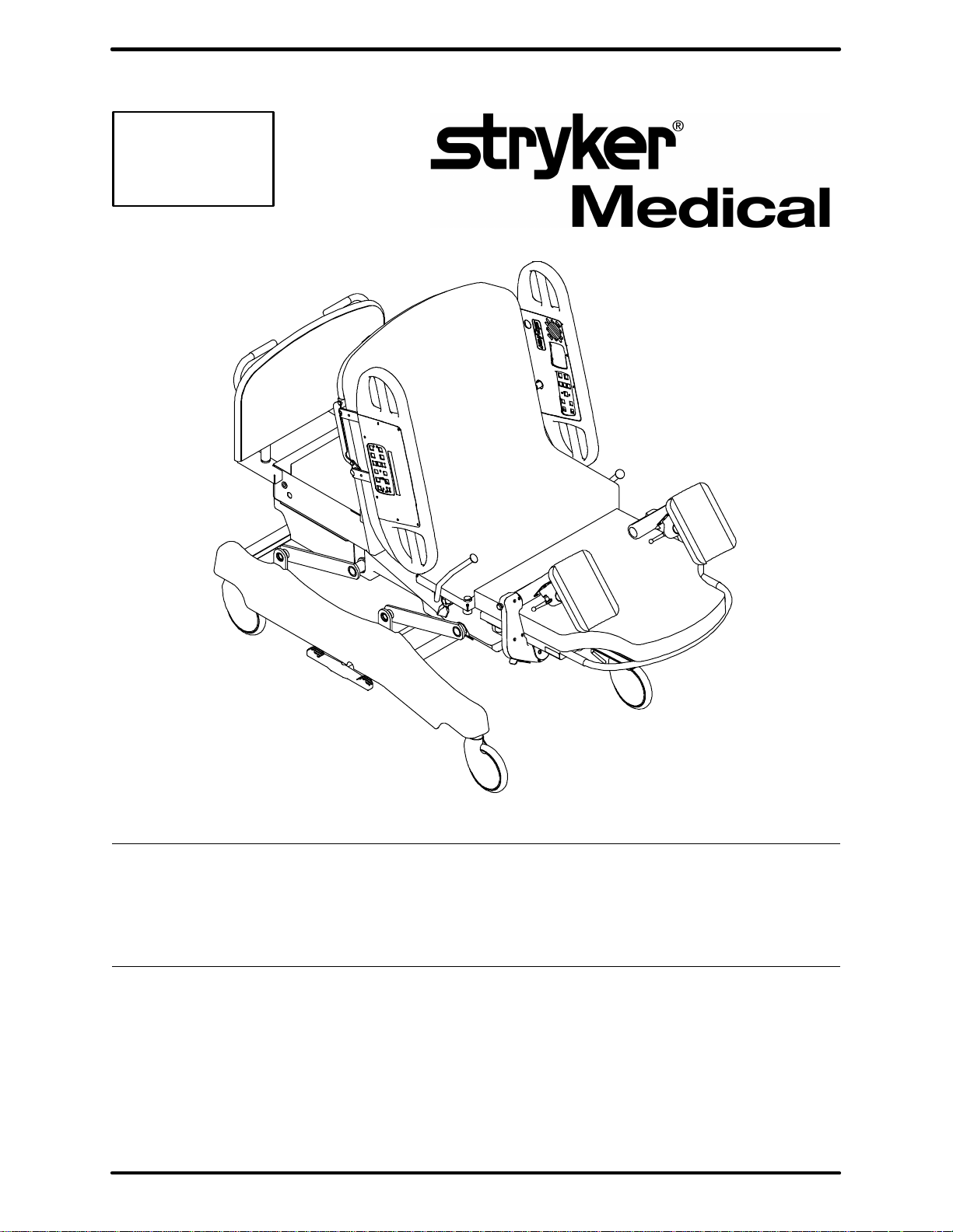
Stryker Adelt Maternity Bed
Models 4700 & 5012
MAINTENANCE MANUAL
For Parts or Technical Assistance
1-800-327-0770 (option 2)
Page 2

Table of Contents
Introduction
Specifications 4. . . . . . . . . . . . . . . . . . . . . . . . . . . . . . . . . . . . . . . . . . . . . . . . . . . . . . . . . . . . . . . . . . . . . . . . . . . .
Warning / Caution / Note Definition 4. . . . . . . . . . . . . . . . . . . . . . . . . . . . . . . . . . . . . . . . . . . . . . . . . . . . . . . . . .
Safety Tips And Guidelines 5. . . . . . . . . . . . . . . . . . . . . . . . . . . . . . . . . . . . . . . . . . . . . . . . . . . . . . . . . . . . . . . . .
Unpacking Instructions 6. . . . . . . . . . . . . . . . . . . . . . . . . . . . . . . . . . . . . . . . . . . . . . . . . . . . . . . . . . . . . . . . . . . . . .
Set-Up Procedures 6. . . . . . . . . . . . . . . . . . . . . . . . . . . . . . . . . . . . . . . . . . . . . . . . . . . . . . . . . . . . . . . . . . . . . . . . .
Bed Symbols and Illustration 7-12. . . . . . . . . . . . . . . . . . . . . . . . . . . . . . . . . . . . . . . . . . . . . . . . . . . . . . . . . . . . . .
Cleaning 13, 14. . . . . . . . . . . . . . . . . . . . . . . . . . . . . . . . . . . . . . . . . . . . . . . . . . . . . . . . . . . . . . . . . . . . . . . . . . . . . .
Preventative Maintenance Checklist 15. . . . . . . . . . . . . . . . . . . . . . . . . . . . . . . . . . . . . . . . . . . . . . . . . . . . . . . . .
Static Discharge Precautions 16. . . . . . . . . . . . . . . . . . . . . . . . . . . . . . . . . . . . . . . . . . . . . . . . . . . . . . . . . . . . . . .
Service Information
Steer Wheel Cable Adjustment 17. . . . . . . . . . . . . . . . . . . . . . . . . . . . . . . . . . . . . . . . . . . . . . . . . . . . . . . . . . . .
Brake Adjustment 17. . . . . . . . . . . . . . . . . . . . . . . . . . . . . . . . . . . . . . . . . . . . . . . . . . . . . . . . . . . . . . . . . . . . . . . .
Lift Motor Removal and Replacement 18, 19. . . . . . . . . . . . . . . . . . . . . . . . . . . . . . . . . . . . . . . . . . . . . . . . . . . .
Trend Motor Removal and Replacement 19. . . . . . . . . . . . . . . . . . . . . . . . . . . . . . . . . . . . . . . . . . . . . . . . . . . .
Fowler In/Out Motor Removal and Replacement 20. . . . . . . . . . . . . . . . . . . . . . . . . . . . . . . . . . . . . . . . . . . . .
Fowler Motor Removal and Replacement 20, 21. . . . . . . . . . . . . . . . . . . . . . . . . . . . . . . . . . . . . . . . . . . . . . . .
Foot Motor Removal and Replacement 21. . . . . . . . . . . . . . . . . . . . . . . . . . . . . . . . . . . . . . . . . . . . . . . . . . . . .
Power Supply Board Replacement 22. . . . . . . . . . . . . . . . . . . . . . . . . . . . . . . . . . . . . . . . . . . . . . . . . . . . . . . . .
CPU Board Replacement 22. . . . . . . . . . . . . . . . . . . . . . . . . . . . . . . . . . . . . . . . . . . . . . . . . . . . . . . . . . . . . . . . .
Optional Power Board Replacement 22. . . . . . . . . . . . . . . . . . . . . . . . . . . . . . . . . . . . . . . . . . . . . . . . . . . . . . . .
Lift, Foot, And Fowler Calibration Procedure 23,24. . . . . . . . . . . . . . . . . . . . . . . . . . . . . . . . . . . . . . . . . . . . . .
Smart TV Interface Burn-In Procedure 25. . . . . . . . . . . . . . . . . . . . . . . . . . . . . . . . . . . . . . . . . . . . . . . . . . . . . .
Troubleshooting Guide 26-28. . . . . . . . . . . . . . . . . . . . . . . . . . . . . . . . . . . . . . . . . . . . . . . . . . . . . . . . . . . . . . . . . .
Bed Circuit Boards 29-34. . . . . . . . . . . . . . . . . . . . . . . . . . . . . . . . . . . . . . . . . . . . . . . . . . . . . . . . . . . . . . . . . . . .
Head Wall Output Configuration 35. . . . . . . . . . . . . . . . . . . . . . . . . . . . . . . . . . . . . . . . . . . . . . . . . . . . . . . . . . . .
CPU/Headwall Jumper Configurations 36. . . . . . . . . . . . . . . . . . . . . . . . . . . . . . . . . . . . . . . . . . . . . . . . . . . . . .
Bed Communications Tester 37. . . . . . . . . . . . . . . . . . . . . . . . . . . . . . . . . . . . . . . . . . . . . . . . . . . . . . . . . . . . . . .
Replacement Parts List 38, 39. . . . . . . . . . . . . . . . . . . . . . . . . . . . . . . . . . . . . . . . . . . . . . . . . . . . . . . . . . . . . . . . .
Assembly Drawings and Parts Lists
Base Assembly 40, 41. . . . . . . . . . . . . . . . . . . . . . . . . . . . . . . . . . . . . . . . . . . . . . . . . . . . . . . . . . . . . . . . . . . . . . .
Brake Adjuster Assembly 42. . . . . . . . . . . . . . . . . . . . . . . . . . . . . . . . . . . . . . . . . . . . . . . . . . . . . . . . . . . . . . . . .
8” Casters Assembly 43. . . . . . . . . . . . . . . . . . . . . . . . . . . . . . . . . . . . . . . . . . . . . . . . . . . . . . . . . . . . . . . . . . . . .
8” Caster Assembly 44. . . . . . . . . . . . . . . . . . . . . . . . . . . . . . . . . . . . . . . . . . . . . . . . . . . . . . . . . . . . . . . . . . . . . .
8” Steer Caster Assembly 45. . . . . . . . . . . . . . . . . . . . . . . . . . . . . . . . . . . . . . . . . . . . . . . . . . . . . . . . . . . . . . . . .
6” Caster Option Assembly 46. . . . . . . . . . . . . . . . . . . . . . . . . . . . . . . . . . . . . . . . . . . . . . . . . . . . . . . . . . . . . . . .
6” Steer Caster Option Assembly 47. . . . . . . . . . . . . . . . . . . . . . . . . . . . . . . . . . . . . . . . . . . . . . . . . . . . . . . . . .
6” Molded Wheel Assembly 48. . . . . . . . . . . . . . . . . . . . . . . . . . . . . . . . . . . . . . . . . . . . . . . . . . . . . . . . . . . . . . .
Litter Assembly 49-52. . . . . . . . . . . . . . . . . . . . . . . . . . . . . . . . . . . . . . . . . . . . . . . . . . . . . . . . . . . . . . . . . . . . . . .
Page 3

Table of Contents
Assembly Drawings and Parts Lists (Continued)
Fowler Motor Assembly 53, 54. . . . . . . . . . . . . . . . . . . . . . . . . . . . . . . . . . . . . . . . . . . . . . . . . . . . . . . . . . . . . . . .
Fowler Potentiometer Assembly 55. . . . . . . . . . . . . . . . . . . . . . . . . . . . . . . . . . . . . . . . . . . . . . . . . . . . . . . . . . .
Front Cover Assembly 56, 57. . . . . . . . . . . . . . . . . . . . . . . . . . . . . . . . . . . . . . . . . . . . . . . . . . . . . . . . . . . . . . . . .
Litter Capacitor Assembly 58. . . . . . . . . . . . . . . . . . . . . . . . . . . . . . . . . . . . . . . . . . . . . . . . . . . . . . . . . . . . . . . . .
Non-In/Out Fowler Assembly 59. . . . . . . . . . . . . . . . . . . . . . . . . . . . . . . . . . . . . . . . . . . . . . . . . . . . . . . . . . . . . .
Skoocher Assembly 60, 61. . . . . . . . . . . . . . . . . . . . . . . . . . . . . . . . . . . . . . . . . . . . . . . . . . . . . . . . . . . . . . . . . . .
Fowler Assembly 62. . . . . . . . . . . . . . . . . . . . . . . . . . . . . . . . . . . . . . . . . . . . . . . . . . . . . . . . . . . . . . . . . . . . . . . .
Square In/Out Fowler Tube Assembly 63. . . . . . . . . . . . . . . . . . . . . . . . . . . . . . . . . . . . . . . . . . . . . . . . . . . . . .
Litter Lift/Trend Assembly 64-67. . . . . . . . . . . . . . . . . . . . . . . . . . . . . . . . . . . . . . . . . . . . . . . . . . . . . . . . . . . . . .
Trend Actuator Assembly 68. . . . . . . . . . . . . . . . . . . . . . . . . . . . . . . . . . . . . . . . . . . . . . . . . . . . . . . . . . . . . . . . .
Lift Actuator Assembly 69. . . . . . . . . . . . . . . . . . . . . . . . . . . . . . . . . . . . . . . . . . . . . . . . . . . . . . . . . . . . . . . . . . . .
Bed Lift/Trend Limits Assembly 70. . . . . . . . . . . . . . . . . . . . . . . . . . . . . . . . . . . . . . . . . . . . . . . . . . . . . . . . . . . .
Bed Lift Potentiometer Assembly 71. . . . . . . . . . . . . . . . . . . . . . . . . . . . . . . . . . . . . . . . . . . . . . . . . . . . . . . . . . .
Foot Lift Assembly 72, 73. . . . . . . . . . . . . . . . . . . . . . . . . . . . . . . . . . . . . . . . . . . . . . . . . . . . . . . . . . . . . . . . . . . .
Foot Potentiometer Assembly 74. . . . . . . . . . . . . . . . . . . . . . . . . . . . . . . . . . . . . . . . . . . . . . . . . . . . . . . . . . . . .
Seat Assembly 75. . . . . . . . . . . . . . . . . . . . . . . . . . . . . . . . . . . . . . . . . . . . . . . . . . . . . . . . . . . . . . . . . . . . . . . . . .
Hand Grip Assembly 76, 77. . . . . . . . . . . . . . . . . . . . . . . . . . . . . . . . . . . . . . . . . . . . . . . . . . . . . . . . . . . . . . . . . .
Glideaway Foot Support Assembly 78. . . . . . . . . . . . . . . . . . . . . . . . . . . . . . . . . . . . . . . . . . . . . . . . . . . . . . . . .
Foot Mattress Assembly 80, 81. . . . . . . . . . . . . . . . . . . . . . . . . . . . . . . . . . . . . . . . . . . . . . . . . . . . . . . . . . . . . . .
Foot Support Upright Assembly 82, 83. . . . . . . . . . . . . . . . . . . . . . . . . . . . . . . . . . . . . . . . . . . . . . . . . . . . . . . . .
Glideaway Assembly 84, 85. . . . . . . . . . . . . . . . . . . . . . . . . . . . . . . . . . . . . . . . . . . . . . . . . . . . . . . . . . . . . . . . . .
Foot Pan Assembly, Left 86. . . . . . . . . . . . . . . . . . . . . . . . . . . . . . . . . . . . . . . . . . . . . . . . . . . . . . . . . . . . . . . . . .
Foot Pan Assembly, Right 87. . . . . . . . . . . . . . . . . . . . . . . . . . . . . . . . . . . . . . . . . . . . . . . . . . . . . . . . . . . . . . . . .
Glideaway Link Assembly, Left 88, 89. . . . . . . . . . . . . . . . . . . . . . . . . . . . . . . . . . . . . . . . . . . . . . . . . . . . . . . . . .
Glideaway Link Assembly, Right 90, 91. . . . . . . . . . . . . . . . . . . . . . . . . . . . . . . . . . . . . . . . . . . . . . . . . . . . . . . .
Electrical Assembly 92-94. . . . . . . . . . . . . . . . . . . . . . . . . . . . . . . . . . . . . . . . . . . . . . . . . . . . . . . . . . . . . . . . . . .
Night Light Assembly 95. . . . . . . . . . . . . . . . . . . . . . . . . . . . . . . . . . . . . . . . . . . . . . . . . . . . . . . . . . . . . . . . . . . . .
No Head Wall Interface Assembly 96. . . . . . . . . . . . . . . . . . . . . . . . . . . . . . . . . . . . . . . . . . . . . . . . . . . . . . . . . .
Pendant Port Assembly with No Nurse Call 97. . . . . . . . . . . . . . . . . . . . . . . . . . . . . . . . . . . . . . . . . . . . . . . . . .
Head Wall Interface Assembly with Nurse Call and No Port 98. . . . . . . . . . . . . . . . . . . . . . . . . . . . . . . . . . . .
Head Wall Interface Nurse Call and Communication Assembly 99. . . . . . . . . . . . . . . . . . . . . . . . . . . . . . . . .
Air Mattress Assembly 100, 101. . . . . . . . . . . . . . . . . . . . . . . . . . . . . . . . . . . . . . . . . . . . . . . . . . . . . . . . . . . . . . .
Power Mattress Assembly 102. . . . . . . . . . . . . . . . . . . . . . . . . . . . . . . . . . . . . . . . . . . . . . . . . . . . . . . . . . . . . . . .
Perineal Pillow Assembly 103. . . . . . . . . . . . . . . . . . . . . . . . . . . . . . . . . . . . . . . . . . . . . . . . . . . . . . . . . . . . . . . .
Manifold Assembly 104. . . . . . . . . . . . . . . . . . . . . . . . . . . . . . . . . . . . . . . . . . . . . . . . . . . . . . . . . . . . . . . . . . . . . .
Siderail Assembly 105-116. . . . . . . . . . . . . . . . . . . . . . . . . . . . . . . . . . . . . . . . . . . . . . . . . . . . . . . . . . . . . . . . . . .
Siderail Latch Assembly 117, 118. . . . . . . . . . . . . . . . . . . . . . . . . . . . . . . . . . . . . . . . . . . . . . . . . . . . . . . . . . . . .
Siderail Bypass Detent Clip Assembly 119. . . . . . . . . . . . . . . . . . . . . . . . . . . . . . . . . . . . . . . . . . . . . . . . . . . . .
Siderail Timing Link Assembly 120, 121. . . . . . . . . . . . . . . . . . . . . . . . . . . . . . . . . . . . . . . . . . . . . . . . . . . . . . . .
Page 4

Table of Contents
Assembly Drawings and Parts Lists (Continued)
Siderail Release Lever Assembly 122, 123. . . . . . . . . . . . . . . . . . . . . . . . . . . . . . . . . . . . . . . . . . . . . . . . . . . . .
Siderail Outer Panel Assembly 124, 125. . . . . . . . . . . . . . . . . . . . . . . . . . . . . . . . . . . . . . . . . . . . . . . . . . . . . . . .
Siderail Lumbar Module Assembly 126, 127. . . . . . . . . . . . . . . . . . . . . . . . . . . . . . . . . . . . . . . . . . . . . . . . . . . .
Siderail Smart TV Module, No Lumbar 128, 129. . . . . . . . . . . . . . . . . . . . . . . . . . . . . . . . . . . . . . . . . . . . . . . . .
Siderail Smart TV Module, With Lumbar 130, 131. . . . . . . . . . . . . . . . . . . . . . . . . . . . . . . . . . . . . . . . . . . . . . .
Pendant Assembly 132. . . . . . . . . . . . . . . . . . . . . . . . . . . . . . . . . . . . . . . . . . . . . . . . . . . . . . . . . . . . . . . . . . . . . .
Wood Head Board Assembly 133. . . . . . . . . . . . . . . . . . . . . . . . . . . . . . . . . . . . . . . . . . . . . . . . . . . . . . . . . . . . .
Crank Handle Assembly 134. . . . . . . . . . . . . . . . . . . . . . . . . . . . . . . . . . . . . . . . . . . . . . . . . . . . . . . . . . . . . . . . .
3-Stage I.V. Mounting Pole Mounting Assembly 135. . . . . . . . . . . . . . . . . . . . . . . . . . . . . . . . . . . . . . . . . . . . .
3-Stage I.V. Pole Assembly 136. . . . . . . . . . . . . . . . . . . . . . . . . . . . . . . . . . . . . . . . . . . . . . . . . . . . . . . . . . . . . .
3rd Stage Assembly 137. . . . . . . . . . . . . . . . . . . . . . . . . . . . . . . . . . . . . . . . . . . . . . . . . . . . . . . . . . . . . . . . . . . . .
I.V. Pole Latch Assembly 138. . . . . . . . . . . . . . . . . . . . . . . . . . . . . . . . . . . . . . . . . . . . . . . . . . . . . . . . . . . . . . . . .
Calf Rests 139. . . . . . . . . . . . . . . . . . . . . . . . . . . . . . . . . . . . . . . . . . . . . . . . . . . . . . . . . . . . . . . . . . . . . . . . . . . . .
Attachable/Storable Calf Rest Assembly, Left 140. . . . . . . . . . . . . . . . . . . . . . . . . . . . . . . . . . . . . . . . . . . . . . .
Attachable/Storable Calf Rest Assembly, Right 141. . . . . . . . . . . . . . . . . . . . . . . . . . . . . . . . . . . . . . . . . . . . . .
Free Standing Calf Rest Assembly 142. . . . . . . . . . . . . . . . . . . . . . . . . . . . . . . . . . . . . . . . . . . . . . . . . . . . . . . .
Labor Bar Assembly 143. . . . . . . . . . . . . . . . . . . . . . . . . . . . . . . . . . . . . . . . . . . . . . . . . . . . . . . . . . . . . . . . . . . . .
Plastic Basin Assembly 144. . . . . . . . . . . . . . . . . . . . . . . . . . . . . . . . . . . . . . . . . . . . . . . . . . . . . . . . . . . . . . . . . .
Stainless Steel Basin Assembly 145. . . . . . . . . . . . . . . . . . . . . . . . . . . . . . . . . . . . . . . . . . . . . . . . . . . . . . . . . . .
Arm Board Assembly 146. . . . . . . . . . . . . . . . . . . . . . . . . . . . . . . . . . . . . . . . . . . . . . . . . . . . . . . . . . . . . . . . . . . .
Multi-Purpose Shelf Assembly 147. . . . . . . . . . . . . . . . . . . . . . . . . . . . . . . . . . . . . . . . . . . . . . . . . . . . . . . . . . . .
Label Assembly 148, 149. . . . . . . . . . . . . . . . . . . . . . . . . . . . . . . . . . . . . . . . . . . . . . . . . . . . . . . . . . . . . . . . . . . . .
Limited Warranty
Obtaining Parts and Service 150. . . . . . . . . . . . . . . . . . . . . . . . . . . . . . . . . . . . . . . . . . . . . . . . . . . . . . . . . . . . . .
Supplemental Warranty Coverage 150. . . . . . . . . . . . . . . . . . . . . . . . . . . . . . . . . . . . . . . . . . . . . . . . . . . . . . . . .
Return Authorization 151. . . . . . . . . . . . . . . . . . . . . . . . . . . . . . . . . . . . . . . . . . . . . . . . . . . . . . . . . . . . . . . . . . . .
Freight Damage Claims 151. . . . . . . . . . . . . . . . . . . . . . . . . . . . . . . . . . . . . . . . . . . . . . . . . . . . . . . . . . . . . . . . . .
Page 5

Introduction
INTRODUCTION
This manual is designed to assist you with the maintenance of the Stryker Adel Maternity Bed. Read it thoroughly before beginning any maintenance on the equipment.
SPECIFICATIONS
Maximum Weight Capacity 500 pounds (227 kilograms)
Bed Length/Width 90” x 41” (with siderails up) - 37” (with siderails down)
229 cm x 104 cm (with siderails up) - 94 cm (with siderails down)
Bed Height (to top of seat) Low - 19” (49 cm), High - 37” (95 cm) (w/8” Casters)
Mattress Size Head - 49.5” (126 cm) x 33” (84 cm) x 5” (13 cm), Foot - 31” (79 cm) x
30” (77 cm) x 3” (8 cm), Patient Sleep Surface - 81” (206 cm)
Critical Angles Maximum Elevation - Head 70, Trendelenburg 8
Break-Away Point from Wall 60” (152 cm)
Electrical Standard 4 motor function: Head-Bed-Foot-Trendelenburg
120 VAC, 60 Hz, 6 Amp - 105 to 135 VAC operating range.
Optional: 230 VY, 50/60 Hz, 6 A - 220 to 240 VAC operating range
Current leakage less than 100 microamperes.
Hospital grade plug and 3-wire heavy duty cord.
Compatible with non-flammable anesthetic agents and oxygen by nasal
catheter or mask.
Caster Size 8” Standard; 6” Optional
Stryker reserves the right to change specifications without notice.
WARNING / CAUTION / NOTE DEFINITION
The words WARNING, CAUTION and NOTE carry special meanings and should be carefully reviewed.
WARNING
The personal safety of the patient or user may be involved. Disregarding this information could result in injury
to the patient or user.
CAUTION
These instructions point out special procedures or precautions that must be followed to avoid damaging the
equipment.
NOTE
This provides special information to make maintenance easier or important instructions clearer.
To ensure safe and proper use, the Stryker Adel Maternity Bed has the following caution and warning labels:
DANGER Explosion Hazard - do not use in the presence of flammable anesthetics.
CAUTION This unit is equipped with a hospital grade attachment plug. Grounding reliability can be
achieved only when equipment is connected to equivalent receptacle.
CAUTION Electrical shock hazard. Do not remove cover panels. Refer all servicing to qualified personnel.
CAUTION Disconnect power cord before using the back up hand crank. Remove hand crank from back
up outlet before connecting power cord.
4
Page 6

Introduction
SAFETY TIPS AND GUIDELINES
Before operating the Stryker Adel Maternity Bed, it is important to read and understand all information in this
manual. Carefully read and strictly follow the safety guidelines listed on this page.
It is important that all users have been trained and educated on the inherent hazards associated with the
usage of electric beds.
WARNING
The Stryker Adel Maternity Bed is equipped with a hospital grade plug for protection against shock haz-
ard. It must be plugged directly into a properly grounded three-prong receptacle. Grounding reliability
can be achieved only when a hospital grade receptacle is used.
Powered bed mechanisms can cause serious injury. Operate bed only when all persons are clear of the
mechanisms.
To help reduce the number and severity of falls by patients, always leave the bed in the lowest position
when the patient is unattended.
Leave the siderails fully up and locked when the patient is unattended. When raising the siderails, listen
for the ”click” that indicates the siderail has locked into the up position. Pull firmly on the siderail to ensure
it is locked into position. Siderails are not intended to be a patient restraint device. It is the responsibility
of the attending medical personnel to determine the degree of restraint necessary to ensure a patient will
remain safely in bed.
Always apply the caster brakes when a patient is getting on or off the bed. Always keep the caster brakes
applied when a patient is on the bed (except during transport). Serious injury could result if the bed moves
while a patient is getting in or out of bed. After the brake pedal is applied, push on the bed to ensure the
brakes are locked. When moving the bed, toggle the steer pedal to put the bed in the steer mode. This
locks the swivel motion of the right foot end caster and makes the bed easier to move.
The instant CPR release is for emergency use only. When activating the instant CPR, all persons and
equipment must be removed from the area below and around the Fowler (back rest) section of the bed
or serious personal injury or damage to the equipment could occur.
When large spills occur in the area of the circuit boards, 110 volt cables and motors, immediately unplug
the bed power cord from the wall socket. Remove the patient from the bed and clean up the fluid. Have
maintenance completely check the bed. Fluids can have an affect on operational capabilities of any electrical product. DO NOT put the bed back into service until it is completely dry and has been thoroughly
tested for safe operation.
Do not steam clean or hose off the bed. Do not immerse any part of the bed. The internal electric parts
may be damaged by exposure to water. Hand wash all surfaces of the bed with warm water and mild
detergent. Dry thoroughly. Inspect the mattress cover after each use. Discontinue use if any cracks or
rips are found in the cover which may allow fluids to enter the mattress. Exposure to fluids may cause
injury to patient and/or user.
Preventative maintenance should be performed at a minimum of annually to ensure all bed features are
functioning as designed. Close attention should be given to safety features including, but not limited to:
Safety side latching mechanisms
Frayed electrical cords and components
All electrical controls return to off or neutral position when released
Caster braking system
No controls or cabling entangled in bed mechanisms
Leakage current 100 MA max.
Always unplug bed during service or cleaning. When working under the bed with the bed in the high posi-
tion, always place blocks under the litter frame and set the brakes to prevent injury in case the Bed Down
switch is accidently pressed.
Unplug the bed power cord from the wall socket before using the hand crank. Remove the hand crank
before plugging the power cord into the wall socket or personal injury could result.
5
Page 7
Unpacking and Initial Set-Up Procedures
UNPACKING INSTRUCTIONS
Refer to unpacking instructions attached to the bed inside the crate.
SET-UP PROCEDURES
It is important that the Stryker Adel Maternity Bed is working properly before it is put into service. The following
list will help ensure that each part of the bed is tested.
Plug the bed into a properly grounded, hospital grade wall receptacle.
WARNING
The Stryker Adel Maternity Bed is equipped with a hospital grade plug for protection against shock hazard.
It must be plugged directly into a properly grounded three-prong receptacle. Grounding reliability can be
achieved only when a hospital grade receptacle is used.
Ensure the siderails raise and lower smoothly and lock in the up position.
Ensure that the brakes hold when the brake pedal is engaged.
Test each function on the (optional) hand pendant to ensure that each function is working properly.
Beds equipped with nurse communication siderail control option only:
Plug the interface cable into the 37 pin connector in the litter frame at the head end of the bed, and into
the ”Patient Station”, ”Head Wall”, ”Docker Station”, or equivalent (whichever applies).
Run through each function on the siderail control panels to ensure that each function is working properly.
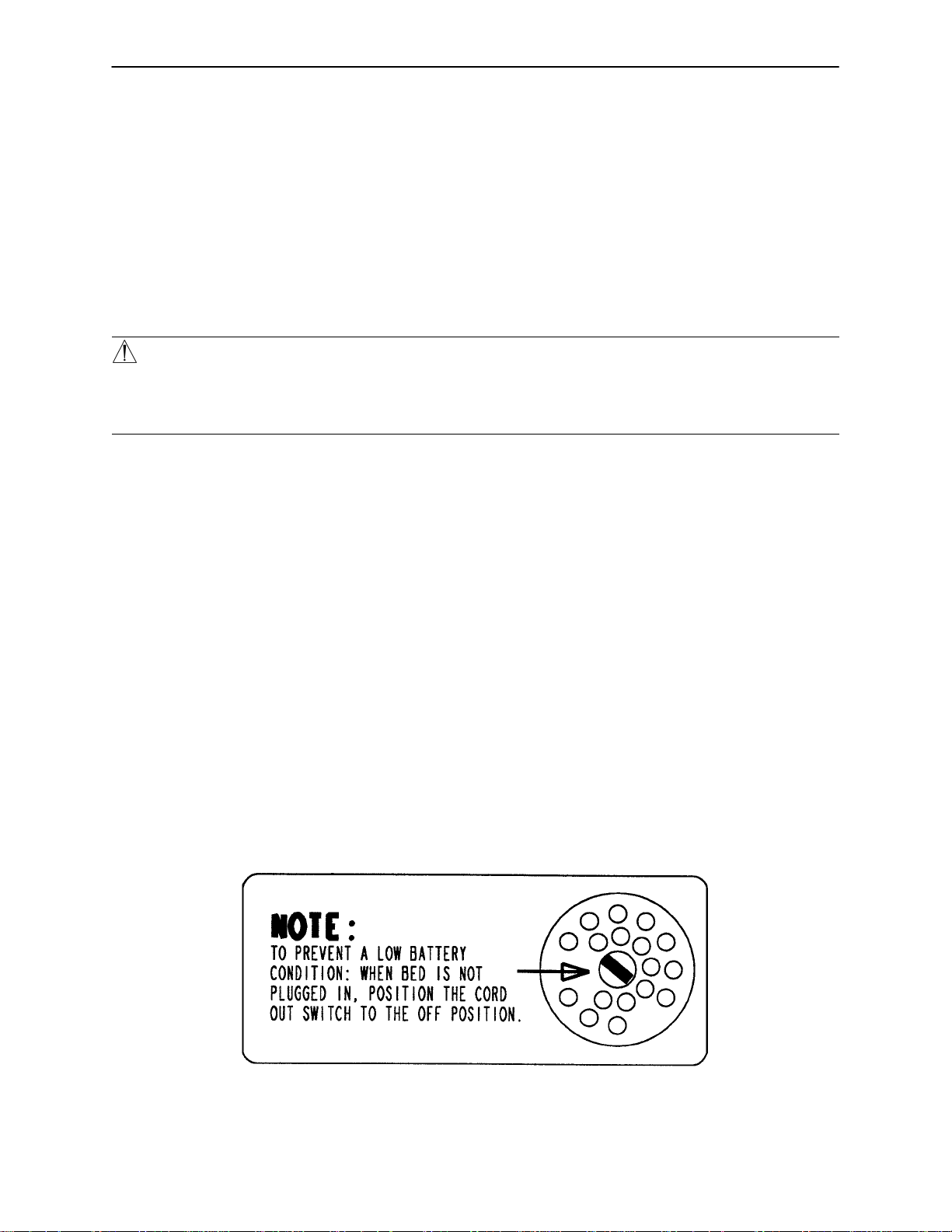
NOTE
To prevent a low battery condition when the bed is not plugged in, position the cord out switch at the head
end of the bed to the off position. The switch is identified by the label shown below. If the switch is not positioned as shown below and the bed power cord and pendant cord are unplugged, the life of the back-up battery will be significantly reduced.
If the siderail lights LED (located on the outside of both siderails) is flashing, the Nurse Call battery needs
to be replaced. The battery is located on the patient’s right side at the head end of the bed. No tools are
required to replace the battery. Unplug the bed power cord from the wall socket and replace the battery. After
replacing the battery, verify the siderail lights LED is no longer flashing and operates normally when the dif ferent light settings are selected.
6
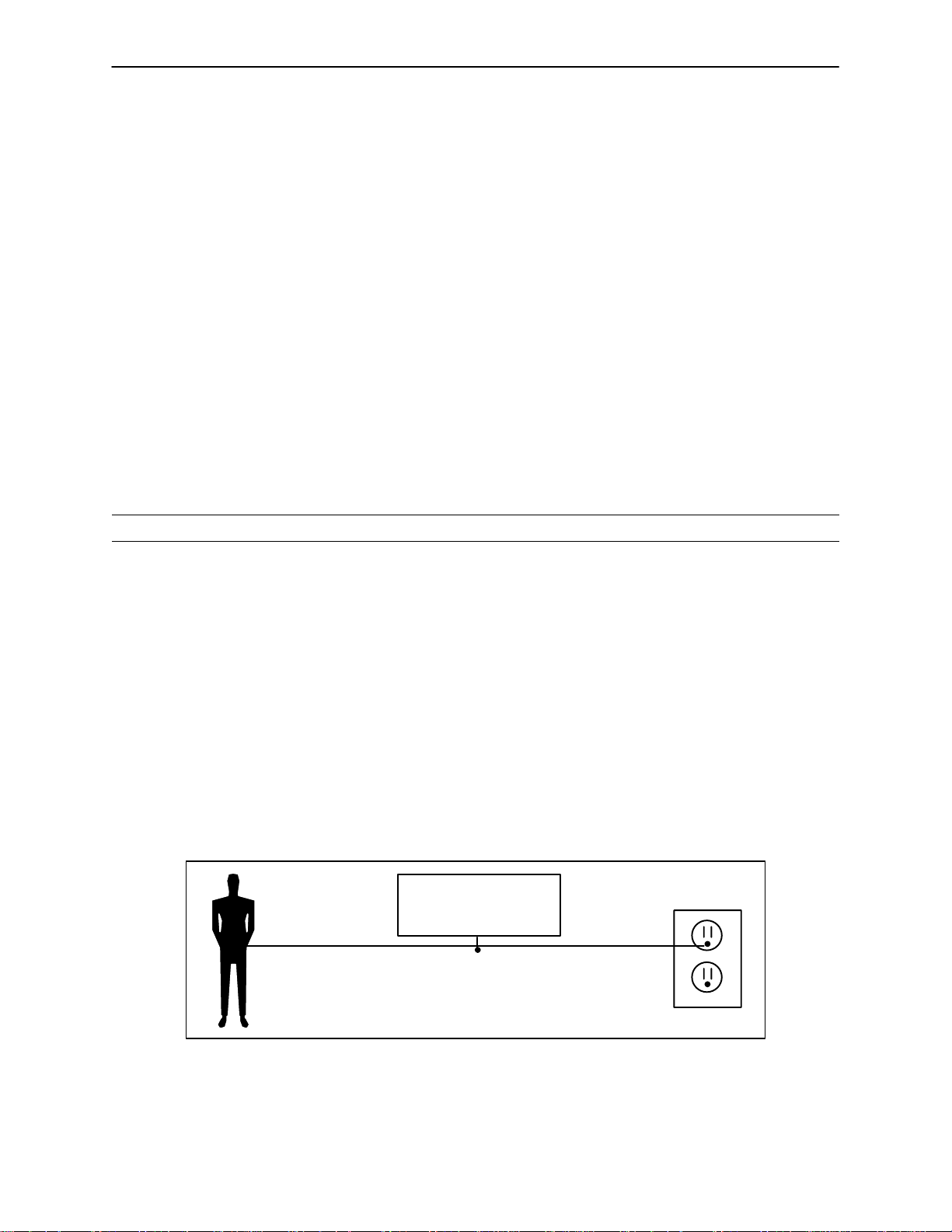
Page 8

Bed Symbols
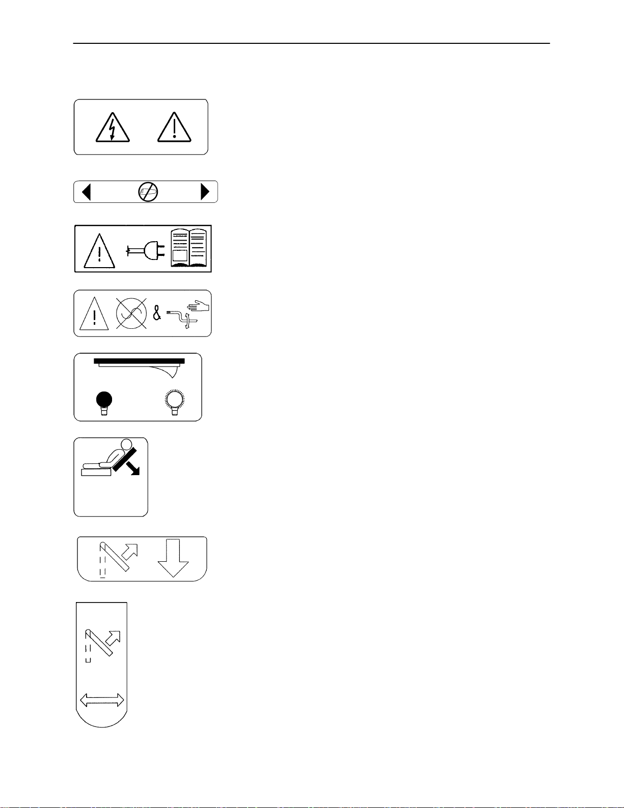
Warning, Refer to Service/Maintenance Manual
~
Alternating Current
Type B Equipment: equipment providing a particular degree of protection against electric shock, particularly regarding allowable leakage current and reliability of the protective earth connection.
Class 1 Equipment: equipment in which protection against electric shock does not rely
on BASIC INSULA TION only, but which includes an additional safety precaution in that
means are provided for the connection of the EQUIPMENT to the protective earth conductor in the fixed wiring of the installation in such a way that ACCESSIBLE METAL
PARTS cannot become live in the event of a failure of the BASIC INSULATION.
Mode of Operation: Continuous
IPX4: Protection from liquid splash
Dangerous Voltage Symbol
Protective Earth Terminal
Potential Equalization Symbol
Medical Equipment Classified by Underwriters Laboratories Inc. with Respect to Electric Shock, Fire, Mechanical and Other Specified Hazards Only in Accordance with UL
2601-1 and CAN/CSA C22.2 No. 601.1
7
Page 9
Bed Symbols
SYMBOL DESCRIPTION
Warning: Potential Electrical Shock if Cover is Removed.
Keep Feet Clear.
Warning: Read all Instructions Before Plugging in the Bed.
Warning: Unplug Bed Before Using the Hand Crank.
Night Light On/Off Switch
CPR Release
Lift to Lower
Lift to Move In or Out
8
Page 10
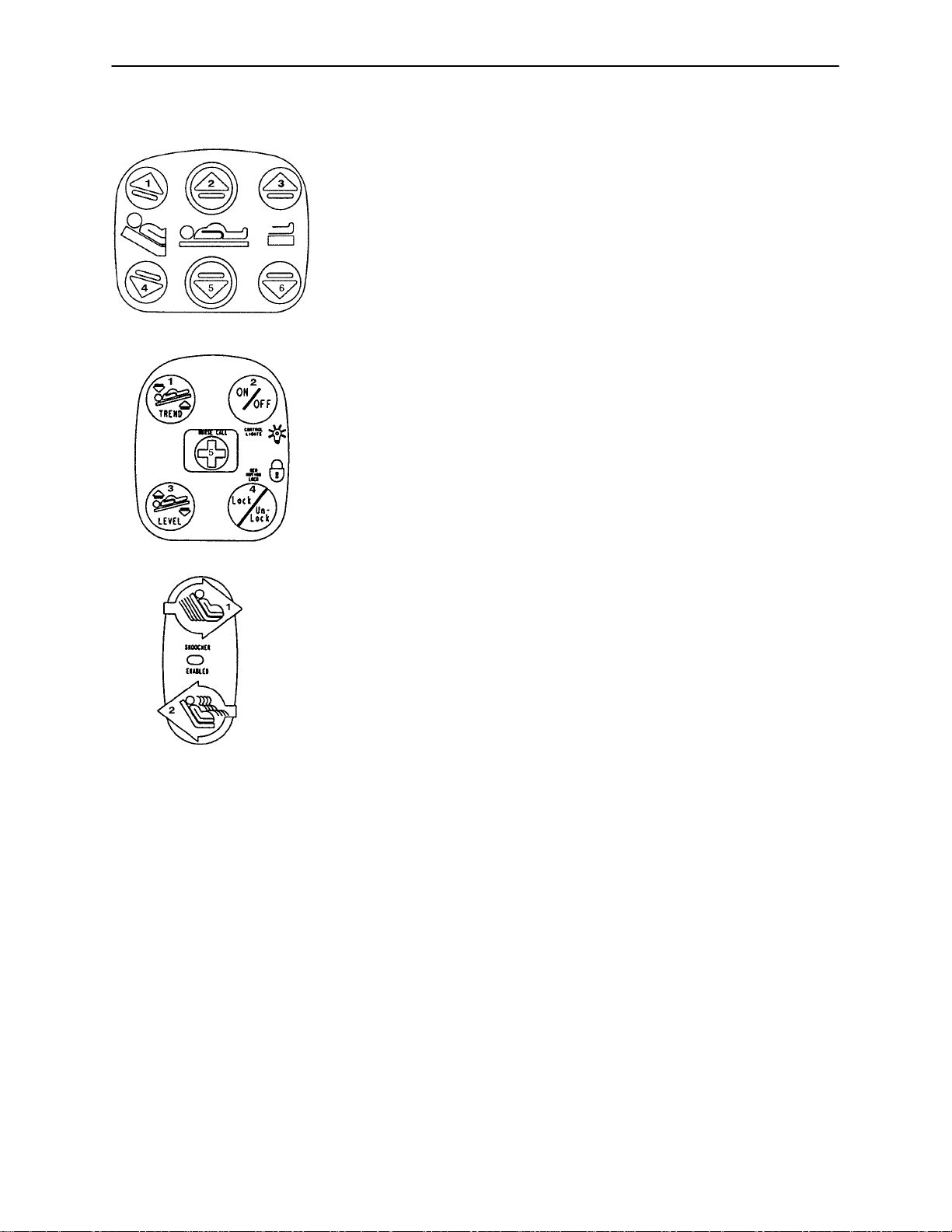
Bed Symbols
SYMBOL DESCRIPTION
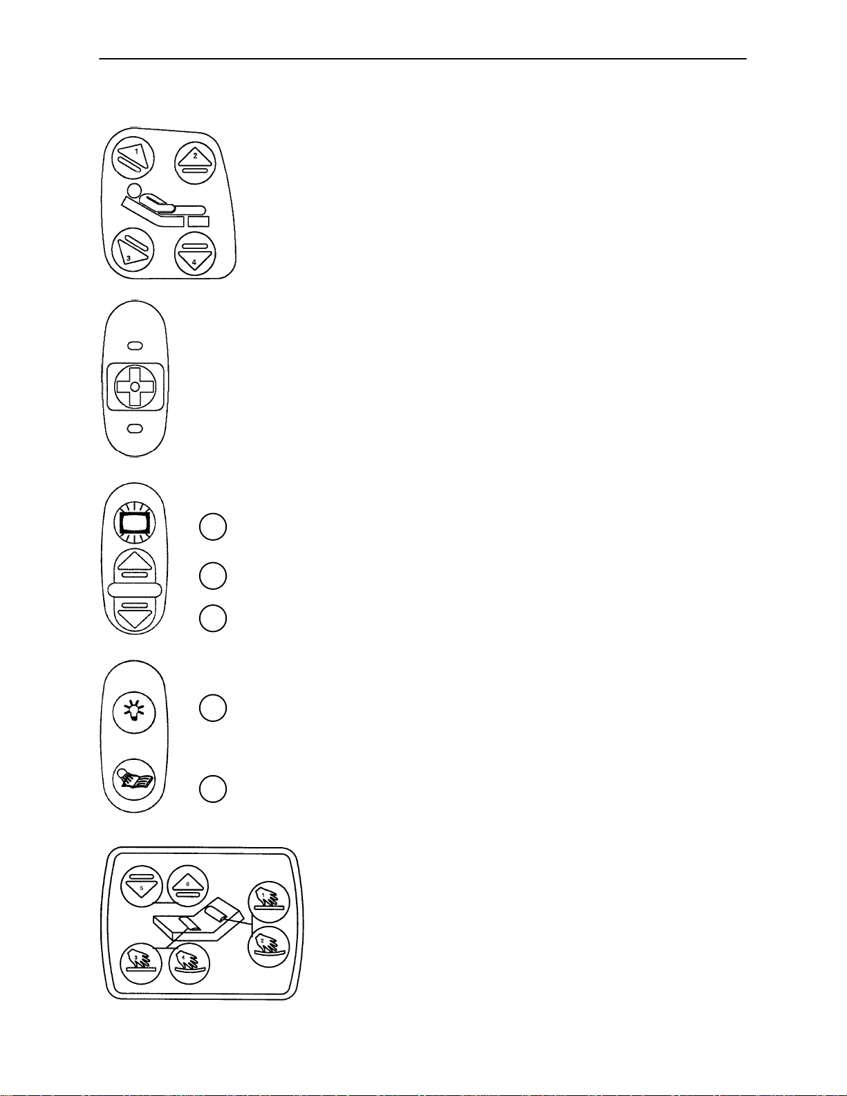
1. Raise Fowler (back rest).
2. Raise foot section.
3. Lower Fowler.
4. Lower foot section.
Activate Nurse Call
1.
2.
3.
1.
2.
1. Turn TV or radio on or select a channel.
2. Increase volume.
3. Decrease volume.
1. Turn the room light on or off.
2. Turn the bed overhead light on or off.
1. More support to the patient’s lower back.
2. Less support to the patient’s lower back.
3. More support to the patient’s seat section.
4. Less support to the patient’s seat section.
5. Lower the volume of the television.
6. Raise the volume of the television.
9
Page 11
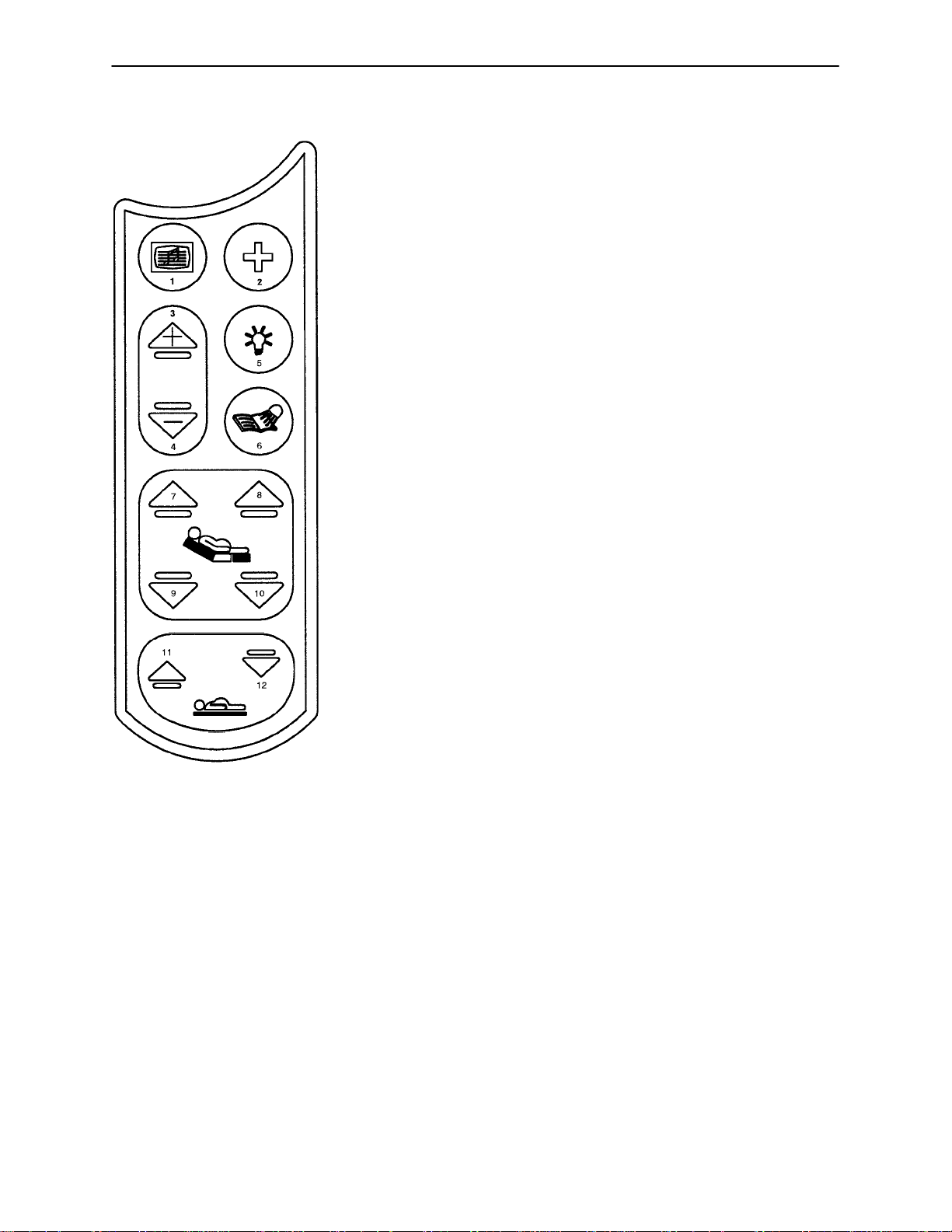
Bed Symbols
SYMBOL DESCRIPTION
1. Raise Fowler (back rest).
2. Raise bed height.
3. Raise foot section.
4. Lower Fowler (back rest).
5. Lower bed height.
6. Lower foot section.
1. Lower head end of bed.
2. Toggle siderail lights to different settings.
3. Raise head end of bed and/or return bed to level.
4. Lock/unlock all bed motion.
5. Activate Nurse Call.
1. Decrease seat depth.
2. Increase seat depth.
10
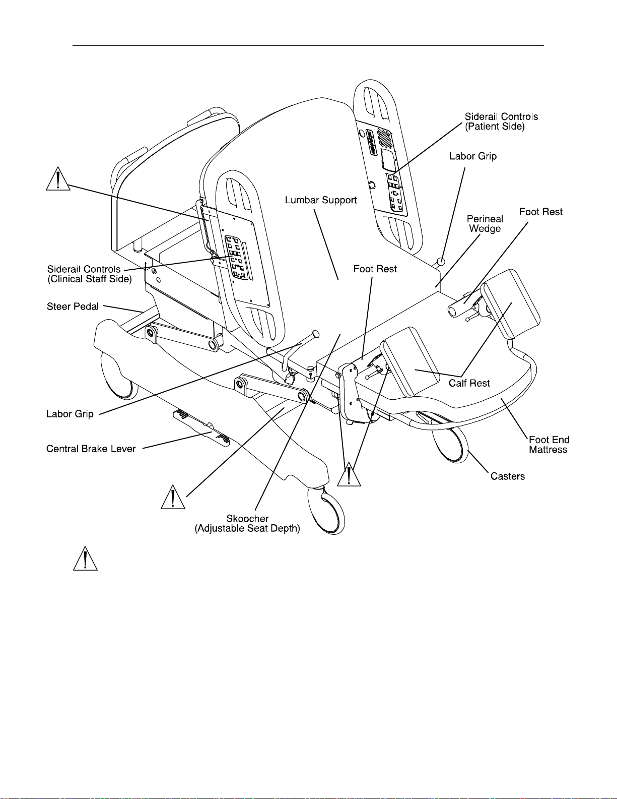
Page 12
Bed Symbols
SYMBOL DESCRIPTION
1. Turn TV or radio on or select a channel.
2. Activate Nurse Call.
3. Increase volume.
4. Decrease volume.
5. Turn the room light on or off.
6. Turn the bed overhead light on or off.
7. Raise Fowler.
8. Raise foot section.
9. Lower Fowler.
10. Lower foot section.
11. Raise bed height.
12. Lower bed height.
11
Page 13
Bed Illustration
WARNING
Potential pinch points
12
Page 14

Cleaning
WARNING
Hand wash all surfaces of the bed with warm water and mild detergent. Dry thoroughly. DO NOT STEAM
CLEAN, PRESSURE WASH, HOSE OFF OR ULTRASONICALLY CLEAN. Using these methods of cleaning
is not recommended and may void this product’s warranty.
Inspect the mattress cover after each use. Discontinue use if any cracks or rips are found in the cover which
may allow fluids to enter the mattress. Exposure to fluids may cause injury to patient and/or user.
In general, when used in those concentrations recommended by the manufacturer, either phenolic type or
quaternary type disinfectants can be used. Iodophor type disinfectants are not recommended for use because staining may result. The following products have been tested and have been found not to have a harmful effect WHEN USED IN ACCORDANCE WITH MANUFACTURERS RECOMMENDED DILUTION.*
TRADE NAME
A33 Quaternary Airwick (Professional Products Division) 2 ounces/gallon
A33 (dry) Quaternary Airwick (Professional Products Division) 1/2 ounce/gallon
Beaucoup Phenolic Huntington Laboratories 1 ounce/gallon
Blue Chip Quaternary S.C. Johnson 2 ounces/gallon
Elimstaph Quaternary Walter G. Legge 1 ounce/gallon
Franklin Phenomysan F2500 Phenolic Purex Corporation 1 1/4 ounce/gallon
Franklin Sentinel Quaternary Purex Corporation 2 ounces/gallon
Galahad Phenolic Puritan Churchill Chemical Company 1 ounce/gallon
Hi-Tor Quaternary Huntington Laboratories 1/2 ounce/gallon
LPH Phenolic Vestal Laboratories 1/2 ounce/gallon
Matar Phenolic Huntington Laboratories 1/2 ounce/gallon
Omega Quaternary Airwick (Professional Products Division) 1/2 ounce/gallon
Quanto Quaternary Huntington Laboratories 1 ounce/gallon
Sanikleen Quaternary West Chemical Products 2 ounces/ gallon
Sanimaster II Quaternary Service Master 1 ounce/gallon
Vesphene Phenolic Vestal Laboratories 1 1/4 ounce/gallon
Wexcide Phenolic Wexford Labs 1/2 ounce/gallon
DISINFECTANT
TYPE
MANUFACTURER
*MANUFACTURER’S
RECOMMENDED
DILUTION
CAUTION
The recommended cleaning solutions for the optional wood head board are furniture polish or a 50% solution
of antibacterial hand soap and water. Any other cleaning solutions may damage the wood finish and should
not be used.
13
Page 15

Cleaning
Quaternary Germicidal Disinfectants, used as directed, and/or Chlorine Bleach products, typically 5.25% So dium Hypochlorite in dilutions ranging between 1 part bleach to 100 parts water, and 2 parts bleach
to 100 parts water are not considered mild detergents. These products are corrosive in nature and
may cause damage to your stretcher if used improperly. If these types of products are used to clean
Stryker equipment, measures must be taken to ensure the equipment is rinsed with clean water and thoroughly dried following cleaning. Failure to properly rinse and dry the equipment will leave a corrosive residue on
the surface, possibly causing premature corrosion of critical components.
NOTE
Failure to follow the above directions when using these types of cleaners may void this product’s warranty.
REMOVAL OF IODINE COMPOUNDS
This solution may be used to remove iodine stains from mattress cover surfaces.
1. Use a solution of 1-2 tablespoons Sodium Thiosulfate in a pint of warm water to clean the stained area.
Clean as soon as possible after staining occurs. If stains are not immediately removed, allow solution
to soak or stand on the surface.
2. Rinse surfaces which have been exposed to the solution in clear water before returning bed to service.
14
Page 16

Preventative Maintenance Checklist
All fasteners secure
All welds intact, not cracked or broken
No bent or broken tubing or sheet metal
No debris in casters
All casters secure and swivel properly
Engage brake pedal and push on the bed to ensure all casters lock securely
Steer caster latches properly
Siderails move and latch properly
Fowler operates properly
Fowler (back rest) Slide operates properly
Bed Up/Down operates properly
Foot operates properly
Trendelenburg operates properly
I.V. pole intact and operating properly
No rips or cracks in mattress cover
Lubricate where required
Replace Nurse Call 9V battery (annually)
Power cord not frayed
No cables worn or pinched
All electrical connections tight
All grounds secure to the frame
Ground impedance not more than 100 milliohms
Current leakage not more than 100 microamps
Serial No.
NOTE
Preventative maintenance should be performed at a minimum of annually. A preventative maintenance program should be established for all Stryker Medical equipment. Preventative maintenance may need to be
performed more frequently based on the usage level of the product.
15
Page 17
Static Discharge Precautions
The electronic circuits in the Stryker Adel Maternity Bed are completely protected from static electricity damage only while the bed is assembled. It is extremely important that all service personnel always use adequate
static protection when servicing the electronic systems of the bed. Whenever you are touching wires or circuit
boards, you should be using static protection.
Static Protection Equipment
The necessary equipment for proper static protection is:
1 static wrist strap; 3M part number 2214 or equivalent,
1 grounding plug; 3M part number 61038 or equivalent,
1 test lead with a banana plug on one end and an alligator clip on the other; Smith part number
N132B699 or equivalent.
Stryker has available the following equipment for proper static protection:
Complete static protection system - part number 3000-000-753
1 grounding plug - Stryker part number 3000-000-754
1 static wrist strap - Stryker part number 3000-000-755
1 test lead - Stryker part number 3000-000-756
CAUTION
All electronic service parts will be shipped in static shielding bags. Do not open the bags until you have completed steps 2 and 3 of the following procedure. All circuit boards must be returned to Stryker Medical. Return
circuit boards in the static shielding bags the new boards were shipped in.
Static Protection Procedure
1. Unplug the power cord from the wall receptacle.
2. Insert the grounding plug into a properly grounded hospital grade wall receptacle. Plug the banana plug
of the test lead into the receptacle on the grounding plug. Connect the alligator clip on the other end of
the test lead to a ground point on the bed.
3. Place the static control wrist strap on your wrist. Connect the alligator clip at the other end of the wrist strap
cord to a ground point on the bed.
BED
GROUNDING DIAGRAM
16
Page 18

Service Information - Base
STEER WHEEL CABLE ADJUSTMENT
Required Tools:
(2) 10 mm Open End Wrenches
Adjustment Procedure:
1. Remove the base frame cover from the (patient) right side of the bed.
2. Position the steer pedal (located at the head end of the bed) in the off position.
3. Using two 10 mm open end wrenches, adjust the steer cable so the steer latch lever is approximately
3/16” away from the caster horn.
4. T est the steer wheel to ensure it engages when the steer pedal is in the on position and disengages when
the steer pedal is in the off position.
5. Reinstall the base cover.
BRAKE ADJUSTMENT
Required Tools:
3/32” Allen Wrench 6” C-Clamp
Adjustment Procedure:
1. Remove the base frame cover on the side of the bed needing service.
2. Put the brake pedal (located at the center of the base frame on both sides of the bed) in the neutral position.
3. Using a 6” C-clamp, clamp the brake bar to the frame to release the tension on the brake adjuster.
4. Using a 3/32” Allen wrench, loosen the set screw on the end of the brake bar.
5. Turn the brake adjuster clockwise to increase the brake tension and counterclockwise to decrease the
brake tension.
NOTE
All four wheel brakes should be set with equal brake tension.
6. Verify the brakes engage and disengage properly.
7. Using the 3/32” Allen wrench, tighten the set screw.
8. Reinstall the base frame cover.
17
Page 19

Service Information - Litter
LIFT MOTOR REMOVAL AND REPLACEMENT
Required Tools:
1/2” Wrench T27 Torx Wrench Hammer
Punch 3/8” Socket Wrench Standard Screwdriver
Snap Ring Pliers 5/16” Nut Driver 3/16” Allen Wrench
5/32” Allen Wrench 9/16” Wrench (2) 2x4’s
Removal Procedure:
1. Raise the bed to the full up position.
NOTE
If the bed will not raise electrically, crank the bed up manually.
2. Remove all accessories from the foot end of the bed (foot pan, mattress, basin, etc.).
3. Using a 5/16” nut driver, remove the 8 bolts holding the bottom cover to the litter.
4. Using a T27 Torx wrench, remove the six bolts holding the seat section to the frame and remove the
seat section.
5. Raise the Fowler to the full up position.
6. Run the Fowler to the full in position (toward the foot end of the bed).
7. Unplug the bed power cord from the wall socket.
8. Using a 3/8” socket wrench, remove the four bolts holding the electrical cover to the electrical pan.
9. Using a 3/8” socket wrench, remove the four bolts holding the electrical pan to the frame.
10. Using a 3/8” socket wrench, remove the two bolts holding the cover over the Fowler motor and remove
the cover.
11. Using a T27 Torx wrench, remove the four screws holding the front cover to the litter. Tilt and support it.
12. Slide the electrical panel toward the head end of the bed.
13. Using a standard screwdriver , remove the screw holding the potentiometer coil to the bed motor drive tube.
CAUTION
The potentiometer coil spring recoils very quickly. Before removing the screw, hold the spring securely to
avoid damaging the potentiometer.
14. Using (2) 2x4’s, support both ends of the bed between the base frame and the crank arms. Using the
manual crank, lower the bed until it is resting on the 2x4’s.
15. Using a hammer and punch, remove the 4 roll pins holding the lift coupler to the drive screw.
WARNING
It is very important to properly support the bed before removing the drive tube bolt or serious personal injury
could result.
16. Using a 3/16” Allen wrench and a 1/2” wrench, remove the bolt from the end of the bed lift drive tube.
17. Remove the drive tube and drive screw from the bed.
18. Disconnect the motor connectors from the CPU board and the capacitor.
19. Using a 1/4” Allen wrench and a 9/16” wrench, remove the trend. link shoulder bolt from the patient/right
side of the bed.
18
Page 20

Service Information - Litter
LIFT MOTOR REMOVAL AND REPLACEMENT (CONTINUED)
Removal Procedure (Continued):
20. Using a 1/4” Allen wrench, remove the two shoulder bolts holding the motor to the litter frame.
21. Move the lift motor assembly toward the head end of the bed.
22. Remove the motor by lowering it and moving it toward the head end of the bed.
23. Reverse the above procedure to reinstall the replacement lift motor. After the replacement lift motor is
installed, all the limits must be set and “burned in”. See page 23 & 24 for potentiometer replacement
and adjustment.
TREND MOTOR REMOVAL AND REPLACEMENT
Required Tools:
7/16” Socket Wrench 3/16” Allen Wrench 11/32” Open End Wrench
5/16” Socket Wrench 1/2” Open End Wrench 1/2” Socket Wrench
3/8” Socket Wrench
Removal Procedure:
1. Raise the bed to the full up position.
2. Remove all accessories from the foot end of the bed (foot pan, mattress, basin, etc.).
3. Using a 5/16” nut driver, remove the 8 bolts holding the bottom cover to the litter.
4. Support the head end of the bed from the head board mounting post to the floor.
WARNING
It is very important to properly support the bed before removing the drive tube bolt or serious personal injury
could result.
5. Unplug the bed power cord from the wall socket.
6. Using a 3/8” socket wrench or nut driver, remove the four 3/8” bolts from the electrical cover and remove
the cover.
7. Using a 3/8” socket wrench or nut driver, remove the two 3/8” bolts holding the holding the Fowler motor
access cover to the electrical pan.
8. Unplug the Trend motor from the litter CPU board.
9. Disconnect the motor to capacitor wires from the capacitor.
10. Using a 3/16“ Allen wrench and 1/2” open end wrench, reach under the bed and remove the bolt and nut
on the end of the drive tube.
11. Using a 11/32” open end wrench, remove the nut from the air compressor.
12. Using a 1/2” open end wrench and a 1/2” socket wrench, remove the four nuts and bolts from the motor
mounting bracket and remove the motor. (When installing the replacement motor, use Loctite 242 on the
bolts.)
13. Reverse the above procedure to install the new motor.
19
Page 21

Service Information - Litter
FOWLER IN-OUT MOTOR REMOVAL AND REPLACEMENT
Required Tools:
3/8” Socket Wrench 5/16” Socket Wrench
Removal Procedure:
1. Raise the bed and the Fowler to the full up position.
2. Run the Fowler to the full out position (toward the head end of the bed).
WARNING
If the Fowler slide will not run electrically, it must be manually cranked out (toward the head of the bed) to
prevent personal injury when the motor is removed. Remove the crank from the two clips at the head end
of the bed. Unplug the bed power cord from the wall socket. Insert the crank into the opening marked with
the Fowler Up/Down symbol. Center the notch in the end of the crank on the roll pin on the motor assembly
and crank to the desired height.
3. Raise the siderails to the full up position.
4. Unplug the bed power cord from the wall socket.
5. Using a 3/8” socket wrench, remove the four bolts holding the electrical cover to the electrical pan and
remove the cover.
6. Using the 3/8” socket wrench, remove the two bolts holding the Skoocher motor access cover to the electrical pan and remove the cover.
7. Using a 5/16” socket wrench, remove the 8 bolts holding the bottom cover to the litter frame and remove
the cover.
8. Disconnect the capacitor wires and the option power board connector for the Fowler slide motor.
9. Using a 3/8” socket wrench, remove the five bolts holding the motor mounting bracket to the frame and
remove the motor.
10. Reverse the above procedure to install the replacement motor.
FOWLER MOTOR REMOVAL AND REPLACEMENT
Required Tools:
3/8” Socket Wrench 5/16” Socket Wrench Tie-Down Straps
Removal Procedure:
1. Raise the bed and the Fowler to the full up position.
2. Raise the siderails to the full up position.
3. Unplug the bed power cord from the wall socket.
4. Using a 3/8” socket wrench, remove the four bolts holding the electrical cover to the electrical pan.
5. Using a 3/ 8 ” socket wrench, remove the two bolts holding the Fowler motor access cover to the electrical
pan and remove the cover.
6. Using a 3/8” socket wrench, remove the four bolts holding the electrical pan to the frame.
7. Unplug the Fowler motor from the main power board.
20
Page 22

Service Information - Litter
FOWLER MOTOR REMOVAL AND REPLACEMENT (CONTINUED)
8. Unplug the capacitor wires.
9. Lift the electrical pan up slightly and turn it sideways on an angle.
WARNING
It is important to properly support the Fowler before proceeding or personal injury could result.
10. Using a 3/8” inch socket wrench, remove the five 5/16” bolts holding the motor mounting bracket to the
litter frame.
11. Lift the motor up and out.
12. Reverse the above procedure to install the replacement Fowler motor.
FOOT MOTOR REMOVAL AND REPLACEMENT
Required Tools:
T27 Torx Driver Hammer Punch
7/16” Socket 9/16” Socket Ratchet
Removal Procedure:
1. Raise the bed to the full up position.
2. Remove all accessories from the foot end of the bed (foot pan, mattress, basin, etc.).
3. Using a 5/16” nut driver, remove the 8 screws holding the bottom cover to the litter.
4. Using a 9/16” socket, remove the bolts holding the left and right foot pan support brackets. (When replacing the brackets during re-assembly, use Loctite 242 on the bolts and torque them to 40 foot-pounds.)
5. Remove the head/seat section mattress.
6. Using a T27 Torx driver, remove the six bolts holding the seat section.
7. Run the foot motor half way up from the bottom stop.
8. Unplug the motor connector from the power board.
9. Unplug the connector from the foot motor capacitor.
10. While holding the motor to prevent it from falling, use a 7/16” wrench to remove the four bolts from the
seat section.
11. Using a hammer and punch, drive the roll pin out of the manual override nut.
12. With the motor and crosstube sitting on the seat frame, push down on the foot motor to force the Acme
nut out of the crosstube and remove the nut from the screw.
13. Unscrew the Acme nut from the motor shaft.
14. Tilt the motor toward the head end of the bed and carefully lift it up and remove it from the bed.
15. Reverse the above procedure to install the replacement foot motor. See page 24 for the potentiometer
adjustment procedure.
21
Page 23

Service Information - Litter
POWER SUPPLY BOARD REPLACEMENT
Required Tools:
3/8” Socket Ratchet Needle Nose Pliers
Procedure:
1. Properly ground yourself (see page 16 for static discharge precautions).
2. Raise the Fowler to the full up position.
3. Unplug the bed power cord from the wall socket.
4. Remove the four 3/8” bolts from the electrical service panel and remove the access cover.
5. Unplug all connectors from the power supply board.
6. Using needle nose pliers, squeeze the four stand-offs and pull up gently on the board to remove it.
7. Reverse the above procedure to install the replacement power supply.
CPU BOARD REPLACEMENT
Required Tools:
3/8” Socket Ratchet Needle Nose Pliers
Removal Procedure:
1. Properly ground yourself (see page 16 for static discharge precautions).
2. Raise the Fowler to the full up position.
3. Unplug the bed power cord from the wall socket.
4. Remove the four 3/8” bolts from the electrical service panel and remove the access cover.
5. Unplug all connectors from the CPU board. Note the location of the connectors so each will be attached
properly to the replacement CPU board. (Reference electrical assembly on pages 101-103).
6. Using needle nose pliers, squeeze the five stand-offs and pull up gently on the CPU board to remove it.
7. Install the replacement CPU board and plug all the connectors into the proper locations.
NOTE
All cables and board connections are lettered to aid with re-connection.
8. All replacement CPU boards must be calibrated. See page 23 & 24 for calibration procedures.
9. Reinstall the access cover.
22
Page 24

Service Information - Litter
OPTIONAL POWER BOARD REPLACEMENT
Required Tools:
3/8” Socket Ratchet 5/16” Nut Driver
Removal Procedure:
1. Properly ground yourself (see page 16 for static discharge precautions).
2. Raise the Fowler to the full up position.
3. Unplug the bed power cord from the wall socket.
4. Remove the four 3/8” bolts from the electrical service panel and remove the access cover.
5. Unplug all connectors from the optional power board.
6. Note the location of each connector so all will be attached properly to the replacement power board.
7. Remove the six 5/16” screws holding the optional power board to the electrical service panel.
8. Reverse the above procedure to install the replacement power board.
NOTE
All cables and board connections are lettered to aid with re-connection. (See electrical assembly on pages
101-103).
LIFT, FOOT, AND FOWLER CALIBRATION PROCEDURE
Required Tools:
Tape Measure Inclinometer Digital Volt Meter
Diagnostics Procedure:
1. Unplug the bed power cord from the wall socket.
2. Press and hold the “head up” and “head down” (Trendelenburg) buttons.
3. While continuing to hold down the “head up” and “head down” buttons, plug the bed power cord into a
properly grounded wall receptacle.
4. Release the “head up” and “head down” buttons. The motion Lock LED will flash, indicating the bed is
in diagnostics mode
Lift Calibration Procedure:
CAUTION
Raise the foot section of the bed to prevent the bed from being damaged when it is lowered.
1. Place the inclinometer on the seat section skin. Level the bed using the “head down” button.
2. Press the “bed down” button and lower the bed until the seat section skin is 19 3/8” above the floor (±1/8”).
3. To set the lift limit:
It is important to press the “head down” button first. The Motion Lock LED will light. Continue to hold
the buttons until the LED blinks on and off.
press first the “head down” (Trendelenburg) button, then the “bed down” button. Note:
23
Page 25

Service Information - Litter
LIFT, FOOT, AND FOWLER CALIBRATION PROCEDURE (CONTINUED)
Lift Calibration Procedure (Continued):
4. Press the “bed up” button and raise the bed until the seat section skin is 37 1/2” above the floor (±1/8”).
5. To set the lift limit:
It is important to press the “head down” button first. The Motion Lock LED will light. Continue to hold the
buttons until the LED blinks on and off.
6. If Fowler or foot section calibration is not necessary, end the calibration procedure by unplugging the bed
power cord from the wall socket.
7. Plug the power cord into the wall socket. Run the bed to full up, then full down to verify the bed limits.
Fowler Calibration Procedure:
1. Adjust the Fowler slide to the full out position. The Fowler down motion will not occur until this limit is met.
2. Press the Fowler down button until the Fowler is flat.
3. To set the Fowler limit:
Note: It is important to press the “head down” button first. The Fowler LED will light. Continue to hold
the buttons until the LED blinks on and off.
4. If lift or foot section calibration is not necessary, end the calibration procedure by unplugging the bed
power cord from the wall socket.
5. Plug the power cord back in to the wall socket. Run the Fowler to full up, then full down to verify the limits.
press first the “head down” (Trendelenburg) button, then the “bed up” button. Note:
press first the “head down” (T rendelenburg) button then the Fowler down button.
Foot Calibration Procedure:
CAUTION
Raise the bed high enough to allow the foot section to be lowered without damaging the bed.
1. Press the “foot down” button until the the foot section reaches full down or the bottom limit.
2. To set the foot limit:
Note: It is important to press the “head down” button first. The LED will light. Continue to hold the buttons
until the LED blinks on and off.
3. If lift or Fowler calibration is not necessary, end the calibration procedure by unplugging the bed power
cord from the wall socket.
4. Plug the power cord back in to the wall socket. Run the foot to full up, then full down to verify the limits.
Potentiometer Initial Settings for Lift, Fowler, and Foot:
Lift Potentiometer (reference page 71)
Looking at the stem of the potentiometer, turn potentiometer fully counterclockwise until it stops, then turn
it back (clockwise) two full turns.
Foot Potentiometer (reference page 74)
Looking at the stem of the potentiometer, turn potentiometer fully counterclockwise until it stops, then turn
it back (clockwise) six full turns.
Fowler Potentiometer (reference page 55)
Looking at the stem of the potentiometer, turn potentiometer fully clockwise until it stops, then turn it back
(counterclockwise) one full turn.
press first the “head down” (Trendelenburg) button, then the “foot down” button.
Upper Limit (35”) 5000 ohms $ 500 ohms 2.5 VDC " 0.2 VDC
HDR 23 + Lead Pin 3, - Lead Pin 2
Upper Limit 3300 ohms " 500 ohms 1.65 VDC " 0.2 VDC
HDR 28 + Lead Pin 3, - Lead Pin 2
Upper Limit (@68) 6750 ohms " 500 ohms 3.37 VDC " 0.2 VDC
HDR 3 + Lead Pin 3, - Lead Pin 4
24
Page 26

Service Information - Litter
SMART TV INTERFACE BURN-IN PROCEDURE
This procedure is used for selecting the style of TV interface desired for your bed. If traditional TV is desired,
no calibration is required. If optional Smart TV is available on the bed, select one of the TV manufacturers
listed in the table below.
SET-UP
Ensure the communication cable is connected between the bed and the Db37 wall port or the pillow
speaker port of the nurse call system. If available, a bed communication tester can be used instead of
the hospital wiring.
PROCEDURE
1. Place the bed in the lift potentiometer burn-in mode (see page 23).
2. Notice the Nurse Call LED (yellow) is flashing. Notice the Nurse Answer LED (green) is flashing on/off
slowly.
3. Press and release the TV ON/OFF switch on the bed’s siderail once. Notice the Nurse Call LED flashes
once. This is the first selection of TV manufacturers for the Smart TV mode. Notice the Nurse Answer
LED (green) is flashing on/off slowly. The Nurse Answer LED will only light when the Nurse Call LED
(yellow) is flashing.
4. Press and release the TV ON/OFF switch on the bed’s siderail to scroll to other TV manufacturers. Notice
the number of times the Nurse Call LED flashes matches the number listed in the table below and represents the TV manufacturer selected.
5. When the desired TV manufacturer has been selected, unplug the bed power cord from the wall socket
and plug it back in to complete the Smart TV burn-in procedure.
NOTE
If the bed is connected to a television during the burn-in procedure, the television will turn on when the correct
setting is selected.
TV MANUFACTURER SELECTION FOR SMART TV BURN-IN PROCEDURE
Press and release TV ON/OFF switch: Nurse Call LED (Yellow) TV Manufacturer
One time One flash RCA 1
Two times Two flashes RCA 2
Three times Three flashes Zenith 1
Four times Four flashes Zenith 2
Five times Five flashes Phillips/Magnavox
Six times Six flashes Magnavox
(models 9120, 9220, 9320)
Seven times Seven flashes Traditional TV
Eight times Eight flashes Traditional Plus
25
Page 27

Electrical Troubleshooting
TROUBLESHOOTING GUIDE
DEFINITIONS:
DMM = Digital Multi-Meter
PCB = Printed Circuit Board
CPU = Central Processing Unit
NOTE
See pages 29-33 for an outline of bed PCB’s and voltage test points. See pages 23 & 24 for potentiometer
calibration.
PROBLEM/FAILURE
No power to bed A. Unplug bed power cord and check continuity of fuses F1 and F2 with
DMM.
B. Check for 120 VAC power at J1 on the power supply, pin 1 and 2.
C. Check for DC voltages on J2 (pins 1,2,3 & 6) on power supply. See
page 32 for power supply voltage test points.
D. If no voltages at J2, unplug connector HDR2 on the CPU board and
recheck for DC voltages at J2 on the power supply.
E. Unplug all cables from the CPU board and recheck voltages.
No bed down motion. A. Enter diagnostics, (see page 23) and press bed down. If motion is
present, re-burn all limits.
B. Check for shunt on HDR3 on pin 1 and 2 on the CPU board.
C. Check for 5VDC on R135 positive lead, CPU ground test point nega-
tive lead while pushing the bed down button.
D. Check for 120 VAC on HDR29, pin 1 white and pin 2 red, of the CPU
board while pushing the bed down button.
No bed up motion. A. Enter diagnostics, (see page 23) and press bed up. If motion is pres-
ent, re-burn all limits.
B. Check for 5VDC on R139 positive lead, CPU ground test point negative lead on the CPU board while pushing the bed up button.
C. Check 120 VAC on HDR29, pin 1 white and pin 3 black, of the CPU
board while pushing the bed up button.
No foot down motion. A. Enter diagnostics, (see page 23) and press foot down. If motion is
present, re-burn all limits.
B. Check for shunt on HDR3 on pin 1 and 2 on the CPU board.
C. Check for 5VDC on R149 positive lead, CPU ground test point nega-
tive lead on the CPU board while pushing the foot down button.
D. If no down motion in diagnostics, check for 120 VAC on HDR34 pin 1
white and pin 3 red of the CPU board while pushing the foot down button.
No foot up motion. A. Enter diagnostics, (see page 23) and press foot up. If motion is pres-
ent, re-burn all limits.
B. Check for 5VDC on R147 positive lead, CPU ground test point negative lead on the CPU board while pushing the foot up button.
C. If no up motion in diagnostics, check for 120 VAC on HDR34, pin 1
white and pin 6 black of the CPU board while pushing the foot up button.
RECOMMENDED ACTION
26
Page 28

Electrical Troubleshooting
TROUBLESHOOTING GUIDE (CONTINUED)
PROBLEM/FAILURE RECOMMENDED ACTION
No Fowler down motion. A. Enter diagnostics, (see page 23) and check for Fowler down motion.
If motion is present, re-burn all limits.
B. If no Fowler down motion is present, check the Fowler Slide Out
switch for proper connection. See item M on page 60 for details.
C. Check for 5VDC on R137 positive lead, CPU ground test point negative lead of the CPU board while pushing the Fowler down button.
D. If no down motion in diagnostics,check for 120 VAC on HDR30 pin 2
red and pin 3 white of the CPU board while pushing the Fowler down
button.
No Fowler up motion. A. Enter diagnostics, (see page 23) and press Fowler up. If motion is
present, re-burn all limits.
B. Check for 5VDC on R141 positive lead, CPU ground test point negative lead of the CPU board while pushing the Fowler up button.
C. If no up motion in diagnostics, check for 120 VAC on HDR30, pin 1
black and pin 3 white of the CPU board while pushing the Fowler up button.
No Trend motion. A. Check for shunt on HDR3 of the CPU board pin 1 and 2.
B. Check for bed up and down limits. If no motion, reference bed motion troubleshooting.
C. Check for 5 VDC on R145 positive lead, CPU ground test point negative lead on the CPU board while pushing the Trend. button.
D. Check for 120 VAC on HDR33, pin 1 white and pin 3 red of the CPU
board while pushing the Trend button.
No Trend Out motion. A. Check for 5 VDC on R143 positive lead, CPU ground test point nega-
tive lead on the CPU board while pushing the Trend. button.
B. Check for 120 VAC on HDR33, pin 1 white and pin 6 black of the
CPU board while pushing the Trend. button.
No Skoocher In (Fowler
Slide In) motion.
No Skoocher Out (Fowler
Slide Out) motion.
A. Check for Fowler up and down limits. If no motion, reference Fowler
troubleshooting.
B. Check for 5 VDC at HDR2, pin 1 (Black) and 2 (White) of the option
power board.
C. Check for 12 VDC at HDR2 pin 1 (Black) and 3 (Red) of the option
power board.
D. Check for 5 VDC on HDR2 pin 1 (Green) and pin 4 (Black) of the option power board while pushing the Skoocher In button.
E. Check for 120 VAC on HDR6, pin 1 Black and pin 3 white of the option power board while pushing the Skoocher In button.
A. Check for Fowler up and down limits. If no motion, reference Fowler
troubleshooting.
B. Check for 5 VDC at HDR2, pin 1 (Black) and 2 (White) of the option
power board.
C. Check for 12 VDC at HDR2 pin 1 (Black) and 3 (Red) of the option
power board.
D. Check for 5 VDC on HDR2 pin 1 (Orange) and 5 (Black) of the option
power board while pushing the Skoocher Out button.
E. Check for 120 VAC on HDR6, pin 2 red and pin 3 white of the option
power board while pushing the Skoocher Out button.
27
Page 29

Electrical Troubleshooting
TROUBLESHOOTING GUIDE (CONTINUED)
PROBLEM/FAILURE RECOMMENDED ACTION
No Lumbar Firm. A. Check for 5VDC on HDR2 pin 1 white and pin 2 black of the option
power board.
B. Check for 12 VDC on HDR2 pin 1 red and pin 3 black of the option
power board.
C. Check for 5 VDC on HDR2 pin 8 red/black and pin 1 black of the option power board while pushing the lumbar firm button.
D. Check for 120 VAC on HDR 4 pin 1 and pin 3 of the option power
board while pushing the lumbar firm button.
No Lumbar Soft. A. Check for 5VDC on HDR2 pin 2 white and pin 1 black of the option
power board.
B. Check for 12 VDC on HDR2 pin 3 red and pin 1 black of the option
power board.
C. Check for 5 VDC on HDR2 pin 7 white/black and pin 1 black of the
option power board while pushing the lumbar soft button.
D. Check for 120 VAC on HDR4 pin 1 and pin 2 of the option power
board while pushing the lumbar soft button.
No Seat Firm. A. Check for 5VDC on HDR2 pin 2 white and pin 1 black of the option
power board.
B. Check for 12 VDC on HDR2 pin 3 red and pin 1 black of the option
power board.
C. Check for 5 VDC on HDR2 pin 10 orange/black and pin 1 black of the
option power board while pushing the seat firm button.
D. Check for 120 VAC on HDR3 pin 1 and pin 3 of the option power
board while pushing the seat firm button.
No Seat Soft A. Check for 5VDC on HDR2 pin 2 white and pin 1 black of the option
power board.
B. Check for 12 VDC on HDR2 pin 3 red and pin 1 black of the option
power board.
C. Check for 5 VDC on HDR2 pin 9 green/black and pin 1 black of the
option power board while pushing the seat soft button.
D. Check for 120 VAC on HDR3 pin 1 and pin 2 of the option power
board while pushing the seat soft button.
No compressor function. A. Check for 5VDC on HDR2 pin 2 white and pin 1 black of the option
power board.
B. Check for 12 VDC on HDR2 pin 3 red and pin 1 black of the option
power board.
C. Check for 5 VDC on HDR2 pin 6 blue and pin 1 black of the option
power board while pushing the lumbar firm or seat firm button.
D. Check for 120 VAC on HDR5 pin 1 and pin 3 of the option power
board while pushing the lumbar firm or seat firm button.
28
Page 30
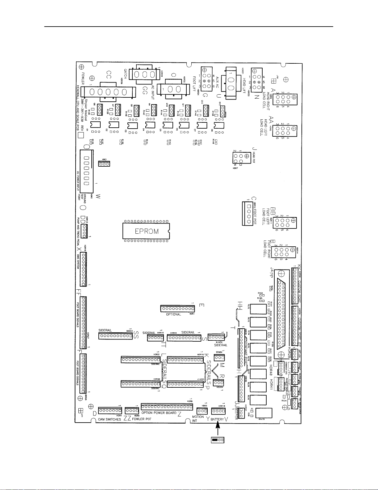
Bed Circuit Boards
CPU BOARD KIT WITH HEAD WALL INTERFACE - P/N 4700-700-4
CPU BOARD KIT WITHOUT HEAD WALL INTERFACE - P/N 4700-700-3
59-137
Shunt for
No Nurse Call
29
Page 31

Bed Circuit Boards
CPU BOARD KIT WITH HEAD WALL INTERFACE - P/N 4700-700-4
CPU BOARD KIT WITHOUT HEAD WALL INTERFACE - P/N 4700-700-3
CONNECTOR
LOCATION
HDR 2 W +12 VDC Pin 1 Pin 4 or 5 Relays & Siderails
HDR 2 W +5 VDC Pin 2 & 3 Pin 4 or 5 DC from Power Supply
HDR 2 W -12 VDC Pin 6 Pin 4 or 5 Relays & Siderails
HDR 6 ZZ +5 VDC Pin 1
HDR 6 ZZ 0 - 5 VDC
HDR 6 ZZ +5VDC Pin 1
HDR 7 J 0 - 5 VDC
HDR 7 J +5 VDC Pin 4
HDR 8 Z +5 VDC Pin 2
HDR 8 Z +12 VDC Pin 3
HDR 8 Z 0 VDC w/o Switch
HDR 8 Z 0 VDC w/o Switch
HDR 8 Z 0 VDC w/o Switch
HDR 8 Z 0 VDC w/o Switch
HDR 8 Z 0 VDC w/o Switch
HDR 8 Z 0 VDC w/o Switch
HDR 8 Z 0 VDC w/o Switch
HDR 12 C +5 VDC Pin 1
HDR 12 C 0 - 5 VDC
HDR 34 GG 0 VAC w/o Switch
HDR 34 GG 0 VAC w/o Switch
CABLE
LOCATION
VOLTAGE POSITIVE
while wipering
while wipering
+5 VDC w/Switch
+5 VDC w/Switch
+5 VDC w/Switch
+5 VDC w/Switch
+5 VDC w/Switch
+5 VDC w/Switch
+5 VDC w/Switch
while wipering
110 VAC w/Switch
110 VAC w/Switch
White/Black
Red/Black
Green/Black
Orange/Black
LEAD
Green
Pin 3
Red
Green
Pin 3
Red
Green
White
Red
Pin 5
Orange
Pin 4
Green
Pin 6
Blue
Pin 7
Pin 8
Pin 9
Pin 10
Black
Pin 3
Red
Pin 6
Black
Pin 3
Red
NEGATIVE
LEAD
Pin 4
Black
Pin 4
Black
Pin 4
Black
Pin 2
Black
Pin 2
Black
Pin 1
Black
Pin 1
Black
Pin 1
Black
Pin 1
Black
Pin 1
Black
Pin 1
Black
Pin 1
Black
Pin 1
Black
Pin 1
Black
Pin 2
Green
Pin 2
Green
Neutral Pin
1 White
Neutral Pin
1 White
DESCRIPTION
Light Voltage
Light Voltage
DC for Fowler
Potentiometer
Fowler Potentiometer
Wiper
DC for Fowler
Potentiometer
Lift Potentiometer
Wiper
DC for Lift
Potentiometer
DC to Option Power
Board
DC to Option Power
Board
Fowler Slide Out
Fowler Slide In
Compressor
Lumbar Soft
Lumbar Firm
Seat Soft
Seat Firm
DC for Foot
Potentiometer
Foot Potentiometer
Wiper
Foot Up
Foot Down
30
Page 32

Bed Circuit Boards
CPU BOARD KIT WITH HEAD WALL INTERFACE - P/N 4700-700-4
CPU BOARD KIT WITHOUT HEAD WALL INTERFACE - P/N 4700-700-3
CONNECTOR
LOCATION
HDR 30 CC 0 VAC w/o Switch
HDR 30 CC 0 VAC w/o Switch
HDR 32 O 110 VAC Pin 1 Pin 2 Line Voltage to Bed
HDR 29 N 0 VAC w/o Switch
HDR 29 N 0 VAC w/o Switch
HDR 33 G 0 VAC w/o Switch
HDR 33 G 0 VAC w/o Switch
CABLE
LOCATION
VOLTAGE POSITIVE
LEAD
Pin 2
120 VAC w/
Switch
120 VAC w/
Switch
120 VAC w/
Switch
120 VAC w/
Switch
120 VAC w/
Switch
120 VAC w/
Switch
Red
Pin 1
Black
Pin 2
Red
Pin 3
Black
Pin 3
Red
Pin 6
Black
NEGATIVE
LEAD
Neutral Pin 3
White
Neutral Pin 3
White
Neutral Pin 1
White
Neutral Pin 1
White
Neutral Pin 1
White
Neutral Pin 1
White
DESCRIPTION
Fowler Down
Fowler Up
Bed Down
Bed Up
Trend.
Trend. Out
31
Page 33

POWER SUPPLY - P/N 59-157
Bed Circuit Boards
CONNECTOR
LOCATION
J1 110V Pin 1 Pin 2
J2 12V Pin 1 Pin 4 or 5
J2 5V Pin 2 Pin 4 or 5
J2 5V Pin 3 Pin 4 or 5
J2 GND Pin 4 Pin 4 or 5
J2 GND Pin 5 Pin 4 or 5
J2 -12V Pin 6 Pin 4 or 5
VOLTAGE POSITIVE LEAD NEGATIVE LEAD
32
Page 34
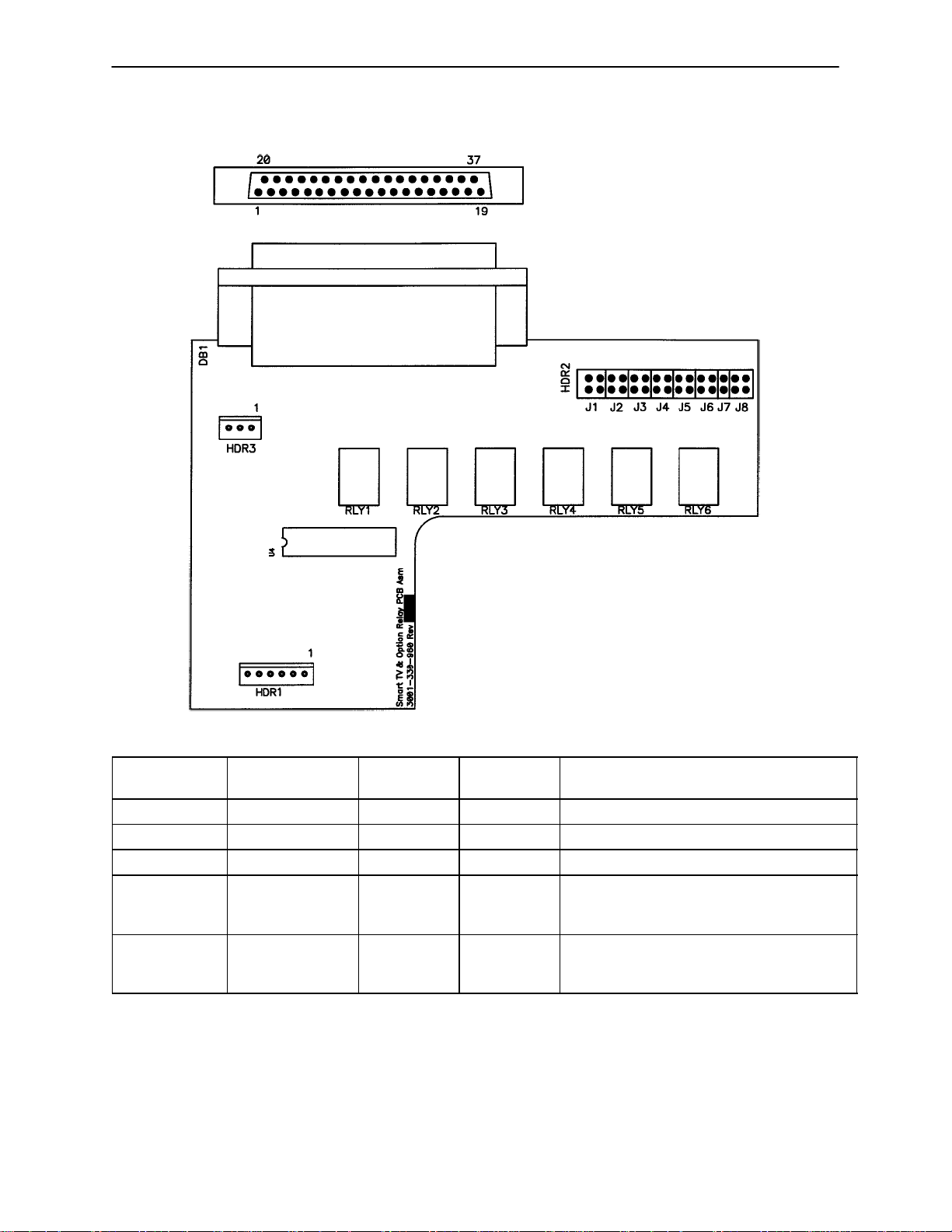
Bed Circuit Boards
OPTION POWER BOARD - P/N 5000-300-900
HDR 11
HDR 5 HDR 7 HDR 8 HDR 1
HDR 2
CONNECTOR
LOCATION
HDR 1 A 120 VAC* Pin 1 Pin 2 AC Line Voltage from
HDR 2 G +5 VDC Pin 2 White Pin 1 Black +5 VDC from CPU
HDR 2 G 12 VDC Pin 3 Pin 1 Black DC Voltage for Relays
HDR 2 G 0 VDC w/o Switch
HDR 2 G 0 VDC w/o Switch
HDR 2 G 0 VDC w/o Switch
HDR 2 G 0 VDC w/o Switch
HDR 2 G 0 VDC w/o Switch
HDR 2 G 0 VDC w/o Switch
HDR 5 E 0 VAC w/o Switch
HDR 5 E 0 VAC w/o Switch
HDR 5 E 0 VAC w/o Switch
HDR 7 C 0 VAC w/o Switch
HDR 7 C 0 VAC w/o Switch
HDR 8 B 0 VAC w/o Switch
HDR 11 F 0 VAC w/o Switch
HDR 11 F 0 VAC w/o Switch
CABLE
LOCATION
VOLTAGE POSITIVE
Pin 5 Orange Pin 1 Black Fowler Slide Out
5 VDC w/Switch
Pin 4 Green Pin 1 Black Fowler Slide In
5 VDC w/Switch
5 VDC w/Switch
Pin 7 White/
5 VDC w/Switch
5 VDC w/Switch
5 VDC w/Switch
120 VAC w/Switch
120 VAC w/Switch
120 VAC w/Switch
120 VAC w/Switch
120 VAC w/Switch
120 VAC w/Switch
120 VAC w/Switch
120 VAC w/Switch
Green/Black
Orange/Black
Pin 3 Black Pin 1 White Compressor
Pin 1 Black Pin 3 White Fowler Slide In
NEGATIVE
LEAD
Pin 6 Blue Pin 1 Black Compressor
Black
Pin 8
Red/Black
Pin 9
Pin 2 Pin 1 Black Seat Soft
Pin 3 Pin 1 Black Seat Firm
Pin 10
Pin 2 Pin 1 Black Lumbar Soft
Pin 3 Pin 1 Black Lumbar Firm
Pin 2 Red Pin 3 White Fowler Slide Out
LEAD
Pin 1 Black Lumbar Soft
Pin 1 Black Lumbar Firm
Pin 1 Black Seat Soft
Pin 1 Black Seat Firm
DESCRIPTION
CPU Board
* 120 VAC present when Fowler slide, lumbar, or seat button is pressed.
33
Page 35
Bed Circuit Boards
OPTIONAL SMART TV CIRCUIT BOARD WITH CUSTOM RELAYS - P/N 3001-330-960
CONNECTOR
LOCATION
HDR 1 5 VDC Pin 2 Pin 1 Regulated 5 VDC Power to the board
HDR 1 Digital Control Pin 3-5 Pin 1 Serial control lines
HDR 1 5 VDC Pin 6 Pin 1 5 VDC for option relay
HDR 3 +5 or +12 VDC 2 Pin 1 Power/control line from the TV
DB1 +5 or +12 VDC Pin 34 Pin 33 Power/Control line from the TV
VOLTAGE POSITIVE
LEAD
NEGATIVE
LEAD
34
DESCRIPTION
Note: This header provides TV control to
a non-Stryker pendant
Note: If this polarity is reversed, place
the shunts of J8 in the alternate position
Page 36
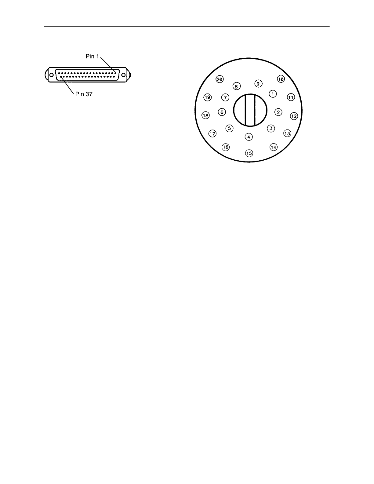
Head Wall Output Configuration
37-PIN CONNECTOR
Pin 1 Option 2 Common
Pin 2 Read Light
Pin 3 Room Light
Pin 4 Speaker High
Pin 5 Pot Wiper
Pin 6 Radio Common
Pin 7 Nurse Call Interlock
Pin 8 Audio Transfer Pin 9 Audio Transfer +
Pin 10 Interlock +
Pin 11 Interlock Pin 12 Spare
Pin 13 Options 3 Common
Pin 14 Pot Low Common
Pin 15 Pot High Common (Std.)/ Audio (STV)
Pin 16 Nurse Answer Light +
Pin 17 Option 1 NO/NC
Pin 18 Option 1 Common
Pin 19 Nurse Call Light +
Pin 20 Option 2 NO/NC
Pin 21 Option 3 NO/NC
Pin 22 Option 3A NO/NC
Pin 23 Option 2A Common
Pin 24 Option 2A NO/NC
Pin 25 Nurse Call +
Pin 26 Nurse Call NO/NC
Pin 27 Room/Read Light Common
Pin 28 Nurse Call Light Pin 29 Nurse Answer Light Pin 30 Priority NO/NC
Pin 31 Priority Common
Pin 32 Option 3A Common
Pin 33 TV - (Std.)/Data (STV)
Pin 34 TV + (Std.)/Common (STV)
Pin 35 Speaker Low Common
Pin 36 Audio Shield
Pin 37 Radio NO/NC
STRYKER PENDANT PORT
1 Scan Line
2 Audio (-)
3 Nurse Call (+)
4 +5 VDC
5 Scan Line
6 Scan Line
7 Nurse Call (-)
8 TV Channel Up
9 Backlight
10 Audio (+)
11 Gatch Up/Fowler In/Foot Up/DMS Firm
12 Gatch Down/Fowler Out/Foot Out/DMS
Soft
13 Fowler Up/Trend In
14 Fowler Down/Trend Out
15 Audio Shield
16 Not Used - Socket Filled
17 Bed Up
18 Ground
19 Read Light/Bed Down
20 Room Light
35
Page 37

CPU/Headwall Jumper Locations
Jumper Locations
J5 - Pot. Wiper/Speaker Pin 4 - Speaker High to Pin 5
Pot. Wiper
J3 - Priority Pin 30 - Priority No Nurse Call to
Pin 31 Priority Common
J2 - Nurse Call Pin 25 - Nurse Call
J1 - Pendant
HDR 41 - Priority Parallel with
Nurse Call
Pin 25 - Nurse Call+ to Pin 31
Priority Common & Pin 26 -
Nurse Call No Nurse Call to Pin
30 Priority No Nurse Call
Default Alternate
Double Shunt - Pin 33 - TV to
Pin 35 - Speaker Low Common
and Pin 14 - Pot Low Common
No Shunts - Separates Pin 33,
Pin 35 & Pin 14
36
Page 38

3001-303-160 Optional Bed Communications Tester
Item Part No. Part Name Qty.
A 3001-303-160 BCT Unit 1
B 3001-303-825 37-Pin Cable 1
C 3001-303-162 Instructions 1
D 3000-303-871 9V Battery 1
37
Page 39

Replacement Parts
PART NAME
Arm Board Assembly 5000-101-3. . . . . . . . . . . . . . . . . . . . . . . . . . . . . . . . . . . . . . . . . . . . . . . . . . . . . . . .
Brake Adjuster 715-201-150. . . . . . . . . . . . . . . . . . . . . . . . . . . . . . . . . . . . . . . . . . . . . . . . . . . . . . . . . . . . . .
Brake Cam Actuator 5000-1-21. . . . . . . . . . . . . . . . . . . . . . . . . . . . . . . . . . . . . . . . . . . . . . . . . . . . . . . . .
Capacitor, Bed Motor 59-140. . . . . . . . . . . . . . . . . . . . . . . . . . . . . . . . . . . . . . . . . . . . . . . . . . . . . . . .
Capacitor, Bed Motor, 230V 59-155. . . . . . . . . . . . . . . . . . . . . . . . . . . . . . . . . . . . . . . . . . . . . . . . . . .
Capacitor, Foot Motor 59-151. . . . . . . . . . . . . . . . . . . . . . . . . . . . . . . . . . . . . . . . . . . . . . . . . . . . . . . .
Capacitor, Foot Motor, 230V 59-153. . . . . . . . . . . . . . . . . . . . . . . . . . . . . . . . . . . . . . . . . . . . . . . . . .
Capacitor, Fowler Motor 59-151. . . . . . . . . . . . . . . . . . . . . . . . . . . . . . . . . . . . . . . . . . . . . . . . . . . . . .
Capacitor, Fowler Motor, 230V 59-153. . . . . . . . . . . . . . . . . . . . . . . . . . . . . . . . . . . . . . . . . . . . . . . .
Capacitor, Fowler Slide Motor 59-151. . . . . . . . . . . . . . . . . . . . . . . . . . . . . . . . . . . . . . . . . . . . . . . . .
Capacitor, Fowler Slide Motor, 230V 59-153. . . . . . . . . . . . . . . . . . . . . . . . . . . . . . . . . . . . . . . . . . .
Capacitor, Trendelenburg Motor 59-151. . . . . . . . . . . . . . . . . . . . . . . . . . . . . . . . . . . . . . . . . . . . . . .
Capacitor, Trendelenburg Motor, 230V 59-153. . . . . . . . . . . . . . . . . . . . . . . . . . . . . . . . . . . . . . . . .
Caster Assembly, 8” 5000-2-34. . . . . . . . . . . . . . . . . . . . . . . . . . . . . . . . . . . . . . . . . . . . . . . . . . . . . . . . .
PART NUMBER
Caster Assembly, Steer, 8” 5000-2-33. . . . . . . . . . . . . . . . . . . . . . . . . . . . . . . . . . . . . . . . . . . . . . . . . . .
Caster Molded Wheel, 8” 715-2-25. . . . . . . . . . . . . . . . . . . . . . . . . . . . . . . . . . . . . . . . . . . . . . . . . . . . .
Caster Assembly, 6” 5000-2-50. . . . . . . . . . . . . . . . . . . . . . . . . . . . . . . . . . . . . . . . . . . . . . . . . . . . . . . . .
Caster Assembly, Steer, 6” 5000-2-50. . . . . . . . . . . . . . . . . . . . . . . . . . . . . . . . . . . . . . . . . . . . . . . . . . .
Caster Molded Wheel, 6” 5000-2-10. . . . . . . . . . . . . . . . . . . . . . . . . . . . . . . . . . . . . . . . . . . . . . . . . . . . .
Communications Tester 3001-303-160. . . . . . . . . . . . . . . . . . . . . . . . . . . . . . . . . . . . . . . . . . . . . . . . . . . . . .
CPU Board Kit, with Head Wall Interface 4700-700-4. . . . . . . . . . . . . . . . . . . . . . . . . . . . . . . . . . . . . . .
CPU Board Kit without Head Wall Interface 4700-700-3. . . . . . . . . . . . . . . . . . . . . . . . . . . . . . . . . . . . .
Crank Handle Assembly 5000-230-320. . . . . . . . . . . . . . . . . . . . . . . . . . . . . . . . . . . . . . . . . . . . . . . . . . . . . .
Fluid Basin, Plastic 5000-30-297. . . . . . . . . . . . . . . . . . . . . . . . . . . . . . . . . . . . . . . . . . . . . . . . . . . . . . . . . .
Fluid Basin, Stainless Steel 5010-201-29. . . . . . . . . . . . . . . . . . . . . . . . . . . . . . . . . . . . . . . . . . . . . . . . . . .
Fluid Basin Liners 8813-320-000. . . . . . . . . . . . . . . . . . . . . . . . . . . . . . . . . . . . . . . . . . . . . . . . . . . . . . . . . . .
Fuse, 7Amp, 3AG, 250 VAC, Slo-Blo 59-150. . . . . . . . . . . . . . . . . . . . . . . . . . . . . . . . . . . . . . . . . .
I.V. Pole, 3-Stage 4700-101. . . . . . . . . . . . . . . . . . . . . . . . . . . . . . . . . . . . . . . . . . . . . . . . . . . . . . . . . . .
Linens (Two Sets) 4700-45-1. . . . . . . . . . . . . . . . . . . . . . . . . . . . . . . . . . . . . . . . . . . . . . . . . . . . . . . . . . .
Mattress Assembly, Foot 4700-41. . . . . . . . . . . . . . . . . . . . . . . . . . . . . . . . . . . . . . . . . . . . . . . . . . . . .
Mattress Assembly, Head w/Electric Lumbar 4700-48. . . . . . . . . . . . . . . . . . . . . . . . . . . . . . . . . . . .
Mattress Assembly, Standard, Enhanced Comfort 4700-45. . . . . . . . . . . . . . . . . . . . . . . . . . . . . . .
38
Page 40

Replacement Parts
PART NAME
Motor, Bed Lift 5010-30-71. . . . . . . . . . . . . . . . . . . . . . . . . . . . . . . . . . . . . . . . . . . . . . . . . . . . . . . . . . . . . .
Motor, Bed Lift, 230V 5012-30-71. . . . . . . . . . . . . . . . . . . . . . . . . . . . . . . . . . . . . . . . . . . . . . . . . . . . . . . .
Motor w/Clutch, Fowler and/or Fowler Slide 5000-30-271. . . . . . . . . . . . . . . . . . . . . . . . . . . . . . . . . . . . .
Motor w/Clutch, Fowler and/or Fowler Slide, 230V 5002-30-271. . . . . . . . . . . . . . . . . . . . . . . . . . . . . . .
Motor, Trendelenburg 5000-230-68. . . . . . . . . . . . . . . . . . . . . . . . . . . . . . . . . . . . . . . . . . . . . . . . . . . . . . . .
Motor, Trendelenburg, 230V 5002-30-68. . . . . . . . . . . . . . . . . . . . . . . . . . . . . . . . . . . . . . . . . . . . . . . . . .
Night Light 59-160. . . . . . . . . . . . . . . . . . . . . . . . . . . . . . . . . . . . . . . . . . . . . . . . . . . . . . . . . . . . . . . . . .
9V Battery 3000-303-871. . . . . . . . . . . . . . . . . . . . . . . . . . . . . . . . . . . . . . . . . . . . . . . . . . . . . . . . . . . . . . . . . .
Option Power Board Assembly 5000-300-900. . . . . . . . . . . . . . . . . . . . . . . . . . . . . . . . . . . . . . . . . . . . . . . .
Paint, Touch-Up, Opal, Bottle w/Brush 7000-1-321. . . . . . . . . . . . . . . . . . . . . . . . . . . . . . . . . . . . . . . . .
Paint, Touch-Up, Opal, Spray Can 7000-1-318. . . . . . . . . . . . . . . . . . . . . . . . . . . . . . . . . . . . . . . . . . . . .
Potentiometer Assembly, Bed 5000-30-225. . . . . . . . . . . . . . . . . . . . . . . . . . . . . . . . . . . . . . . . . . . . . . . . .
Potentiometer Assembly, Foot 5000-30-317. . . . . . . . . . . . . . . . . . . . . . . . . . . . . . . . . . . . . . . . . . . . . . . .
Potentiometer Assembly, Fowler 5000-30-316. . . . . . . . . . . . . . . . . . . . . . . . . . . . . . . . . . . . . . . . . . . . . .
PART NUMBER
Power Cord Assembly, 110V 39-248. . . . . . . . . . . . . . . . . . . . . . . . . . . . . . . . . . . . . . . . . . . . . . . . . .
Power Supply 59-157. . . . . . . . . . . . . . . . . . . . . . . . . . . . . . . . . . . . . . . . . . . . . . . . . . . . . . . . . . . . . . .
Shelf Assembly 5000-101-44. . . . . . . . . . . . . . . . . . . . . . . . . . . . . . . . . . . . . . . . . . . . . . . . . . . . . . . . . . . . .
Siderail Lumbar PCB Board, Left 5000-400-930. . . . . . . . . . . . . . . . . . . . . . . . . . . . . . . . . . . . . . . . . . . . . .
Siderail Lumbar PCB Board, Right 5000-400-920. . . . . . . . . . . . . . . . . . . . . . . . . . . . . . . . . . . . . . . . . . . . .
Siderail Main PCB Board Assembly 3001-400-930. . . . . . . . . . . . . . . . . . . . . . . . . . . . . . . . . . . . . . . . . . . .
Siderail Outside PCB Board Assembly, Left 4700-400-910. . . . . . . . . . . . . . . . . . . . . . . . . . . . . . . . . . . . .
Siderail Outside PCB Board Assembly, Right 4700-400-900. . . . . . . . . . . . . . . . . . . . . . . . . . . . . . . . . . . .
39
Page 41
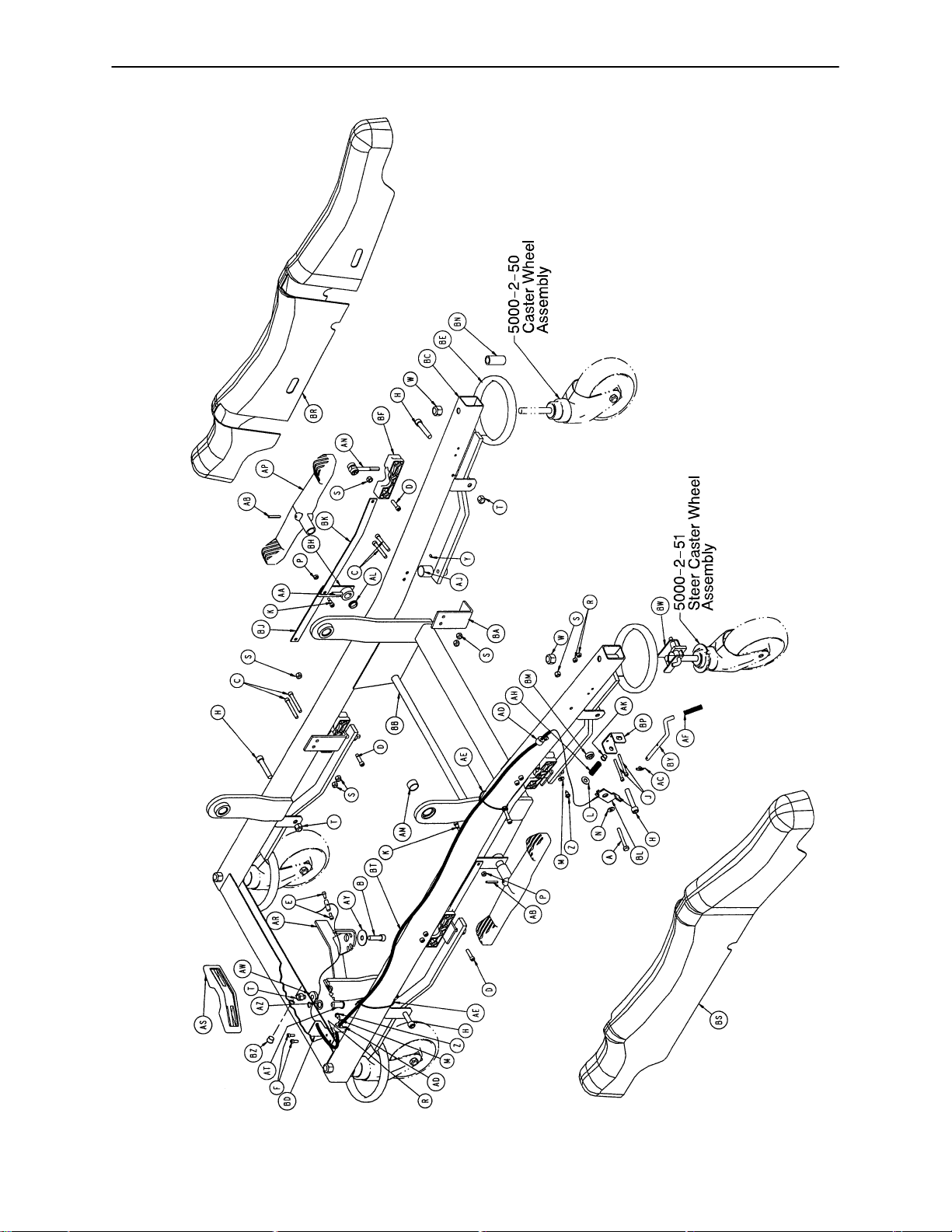
Base Assembly
NOTE
Reference page 158 & 159 for labels.
NOTE
Optional 6” caster is shown.
Reference page 43 for 8” casters.
Assembly part number 5000-1 (reference only)
40
Page 42

Base Assembly
Item Part No. Part Name Qty.
A 3-79 Hex Hd. Cap Screw 1
B 4-12 Soc. Hd. Cap Screw 1
C 4-24 Soc. Hd. Cap Screw 8
D 4-28 Soc. Hd. Cap Screw 4
E 4-298 Soc. Hd. Cap Screw 2
F 4-32 Soc. Hd. Cap Screw 2
H 4-86 Soc. Hd. Cap Screw 4
J 4-114 Soc. Hd. Cap Screw 2
K 8-7 Soc. Hd. Shoulder Bolt 2
L 11-3 Washer 1
M 11-302 Flat Washer 2
N 11-280 Washer 1
P 16-2 Fiberlock Nut 2
R 16-3 Fiberlock Nut 4
S 16-28 Nylock Nut 13
T 16-12 Flexlock Nut 5
W 16-57 Fiberlock Nut 4
Y 21-50 Set Screw 4
Z 23-25 Hex Washer Hd. Tap. Screw 2
AA 26-13 Spring Pin 2
AB 26-261 Groove Pin 2
AC 27-21 Rue Ring Cotter 1
AD 34-254 Cable Clamp 2
AE 38-151 Cable Tie 2
AF 38-211 Extension Spring 1
AH 38-390 Compression Spring 1
AJ 38-395 Brake Compression Spring 4
AK 52-245 Nyliner Bearing 1
AL 52-301 Nyliner Bearing 2
AM 81-270 DU Bearing 4
AN (page 42) Brake Adjuster Assembly 4
AP 715-201-201 Brake/Steer Pedal 2
AR 3000-200-335 Steer Pedal Arm 1
AS 3000-200-336 Steer Pedal 1
AT 3000-200-337 Ball Plunger 1
AW 3000-200-341 Steer Pedal Bushing 1
AY 3000-200-348 Special Wide Washer 1
AZ 3000-200-349 Special Narrow Washer 1
BA 5000-1-3 Brake Cam Bracket 4
BB 5000-1-6 Base Brake Rod 1
BC 5000-1-10 Base Frame Weldment 1
BD 5000-1-14 Steer Cable Plate 1
BE 5000-1-20 Caster Brake Assembly 4
BF 5000-1-21 Brake Cam Actuator 4
BH 5000-1-23 Brake Actuator Weldment 2
BJ 5000-1-26 Brake Link, Head End 2
BK 5000-1-27 Brake Link, Foot End 2
BL 5000-1-33 Steer Lock Cable Lever 1
BM 5000-1-34 Steer Lock Lever Bushing 1
BN 5000-1-35 Caster Sleeve 4
BP 5000-1-36 Steer Lock Guide Bracket 1
BR 5000-1-38 Base Hood, Left 1
BS 5000-1-39 Base Hood, Right 1
BT 5000-1-40 Steer Lock Cable 1
BW 5000-2-40 Steer Lock Assembly 1
BY 5050-1-270 Steer Lock Linkage 1
BZ 59-100 Dome Plug 1
41
Page 43
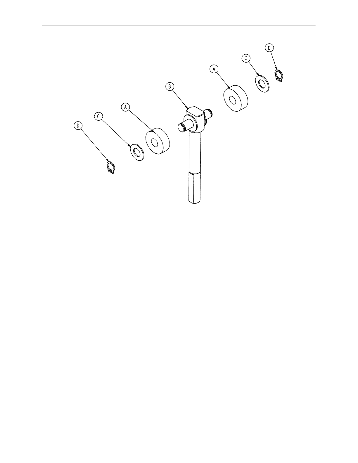
715-201-150 Brake Adjuster Assembly
Item Part No. Part Name Qty.
A 715-1-180 Cam Bearing 2
B 715-201-62 Threaded Stud Assembly 1
C 14-4 Nylon Washer 4
D 28-8 External Retaining Ring 2
42
Page 44

Assembly part number 5000-1-32
8” Caster Assembly
Item Part No. Part Name Qty.
A 11-225 Washer 8
B (page 45) 8” Steer Caster Assembly 1
C (page 44) 8” Caster Assembly 3
43
Page 45

5000-2-34 8” Caster Assembly
Item Part No. Part Name Qty.
A 3-99 Hex Hd. Cap Screw 1
B 3-227 Hex Hd. Cap Screw 1
C 11-310 Washer 1
D 16-60 Hex Nut 1
E 5000-2-29 Caster Horn w/Bearing 1
F 2025-1-47 Wheel Cover, Right 1
H 2025-1-48 Wheel Cover, Left 1
J 715-2-25 Molded Wheel Assembly 1
44
Page 46

5000-2-33 8” Steer Caster Assembly
Item Part No. Part Name Qty.
A 3-99 Hex Hd. Cap Screw 1
B 3-227 Hex Hd. Cap Screw 1
C 11-310 Washer 1
D 16-60 Hex Nut 1
E 2025-1-47 Wheel Cover, Right 1
F 2025-1-48 Wheel Cover, Left 1
H 715-2-25 Molded Wheel Assembly 1
J 5000-2-32 Steer Caster Weldment 1
45
Page 47

5000-2-50 Optional 6” Caster Assembly
Item Part No. Part Name Qty.
A 3-205 Hex Hd. Cap Screw 1
B 3-227 Hex Hd. Cap Screw 1
C 11-310 Washer 2
D 16-60 Hex Nut 1
E (page 48) Wheel Assembly 1
F 5000-2-30 Caster Horn Assembly 1
46
Page 48
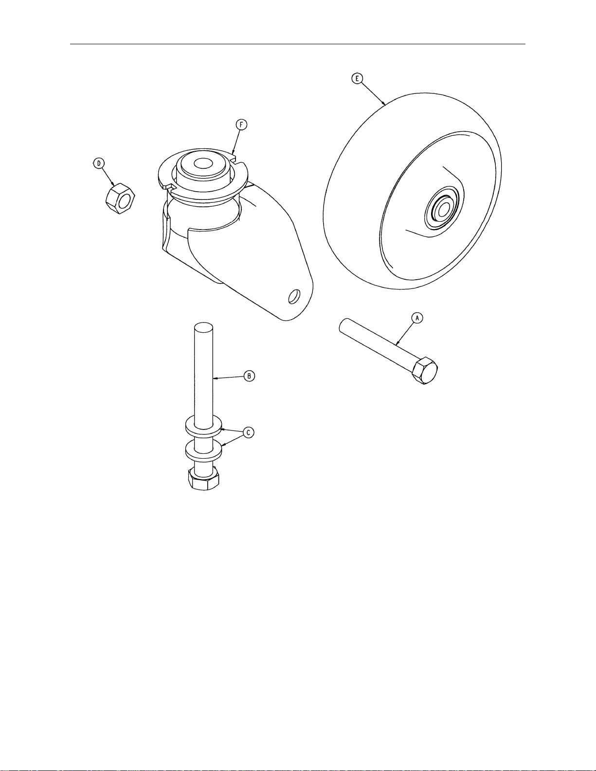
5000-2-51 Optional 6” Steer Caster Assembly
Item Part No. Part Name Qty.
A 3-205 Hex Hd. Cap Screw 1
B 3-227 Hex Hd. Cap Screw 1
C 11-310 Washer 2
D 16-60 Hex Nut 1
E (page 48) Wheel Assembly 1
F 5000-2-31 Steer Caster Horn Ass’y1
47
Page 49

5000-2-10 Optional 6” Molded Wheel Assembly
Item Part No. Part Name Qty.
A 81-226 Bearing 2
B 715-1-255 Wheel Bushing 2
C 5000-2-20 Molded Wheel 1
D 6060-2-46 Bearing Spacer 1
48
Page 50
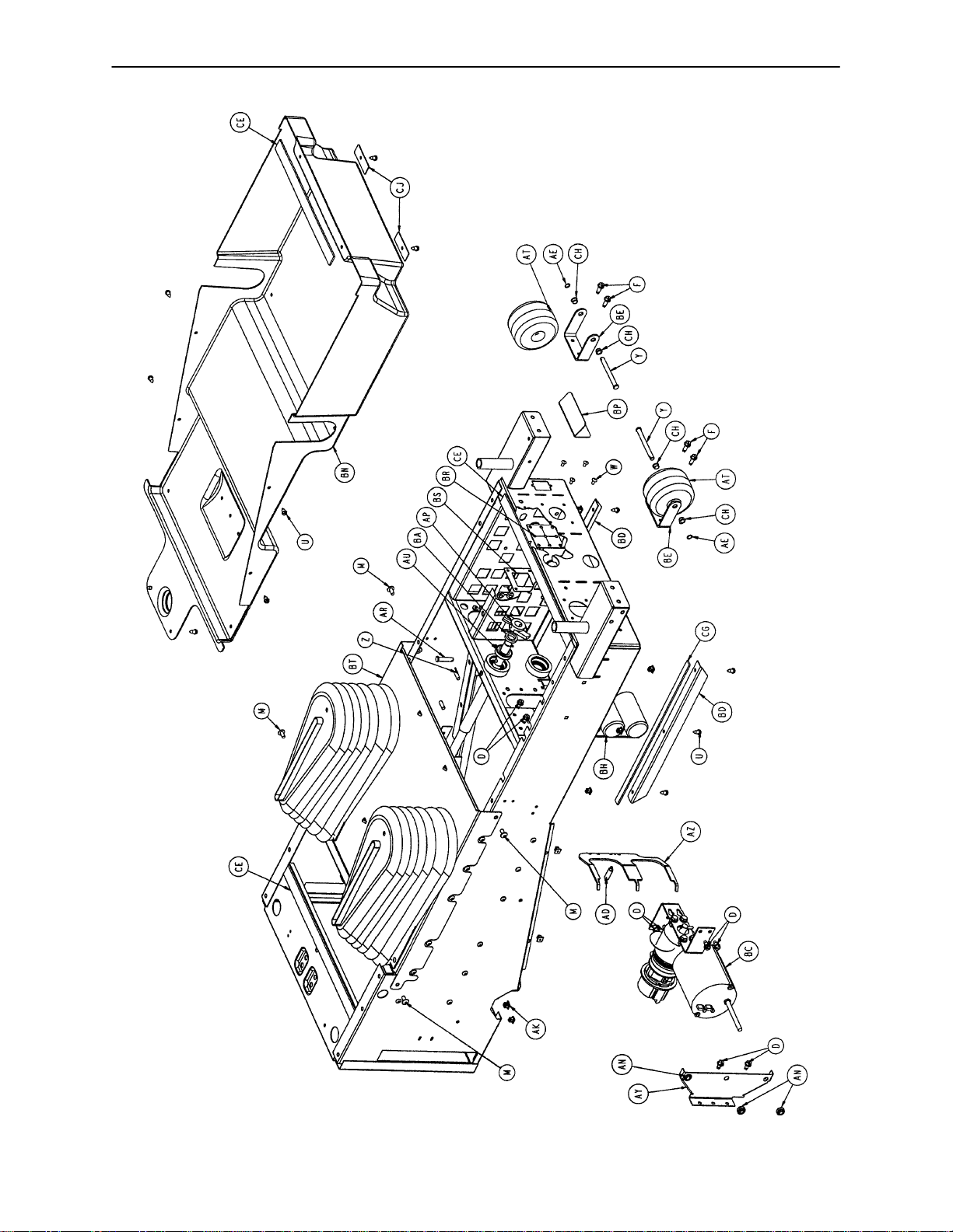
Litter Assembly
Assembly part numbers 4700-30 &
4702-30 (230V)
(reference only)
49
Page 51

Litter Assembly
50
Page 52
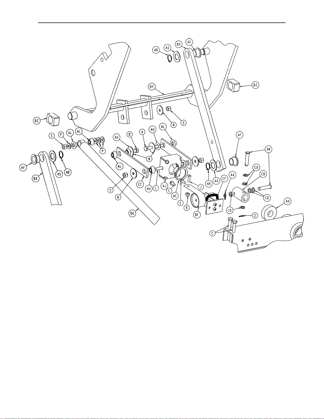
Litter Assembly
51
Page 53

Litter Assembly
Item Part No. Part Name Qty. Item Part No. Part Name Qty.
A 3-47 Hex Hd. Cap Screw 1 AS 3000-300-482 Thrust Washer 4
B 3-76 Hex Hd. Cap Screw 1 AT 3000-335-1 1 Roller Bumper 2
C 8803-016-000 Hex Hd. Cap Screw 4 AU 81-268 Flange Bushing 4
D 3-221 Hex Washer Hd. Screw 8 AW 3001-300-471 Roller Bearing 1
E 3-224 Hex Washer Hd. Screw 2 AX 5000-30-62 Slide Bearing 16
F 3-226 Hex Washer Hd. Screw 4 AY 5000-30-160 CPR Actuator Bracket 1
G 4-15 Soc. Hd. Cap Screw 2 AZ 5000-30-161 Double Horseshoe Brkt. 1
H 4-489 H. Soc. But. Hd. Cap Scr. 24 BA 5000-30-223 Bearing Spacer 1
J 4-304 H. Soc. But. Hd. Cap Scr. 1 BB 5000-30-255 Thrust Collar 1
K 4-198 But. Hd. Cap Screw 1 BC (page 53) Fowler Motor/CPR Ass’y1
L 5-22 Carriage Bolt 2 BD 5000-30-285 Hood Bracket 2
M 7-58 Truss Hd. Torx 4 BE 5010-30-79 Roller Bumper Bracket 2
N 11-53 Washer 5 BF (page 55) Fowler Pot. Assembly 1
P 11-63 Washer 4 BG 5000-30-328 CPR Dampener 1
R 16-3 Nylock Nut 1 BH (page 58) Capacitor Assembly 1
S 16-28 Nylock Nut 9 BJ 5000-30-366 Fowler Nut Adaptor 1
T 16-102 Fiberlock Jam Nut 24 BL 5000-30-397 Fowler In/Out Weldment 1
U 23-25 Hex Washer Hd. Tap. Scr. 18 BM 5000-230-91 Fowler Ball Screw Ass’y1
W 25-50 Pop Rivet 6 BN 5000-230-229 Litter Bottom Cover 1
X 26-168 Spirol Pin 1 BP 5002-30-69 Inlet Filter Splash Cover 1
Y 26-278 Clevis Pin 2 BR 5002-30-70 Man. Over. Splash Gask. 1
Z 27-17 Cotter Pin 2 BS 5002-30-71 Over. Gask. Backer Plate 1
AA 27-20 Rue Ring Cotter 1 BT (page 56 & 57) Front Cover Assembly 1
AB 28-23 External Retaining Ring 4 BU 5010-30-24 Fowler Slide, Left 1
AC 28-120 External Retaining Ring 1 BW 5010-30-25 Fowler Slide, Right 1
AD 38-404 CPR Extension Spring 1 BX 4700-30-30 Fowler Link 2
AE 52-727 Grooveless Ret. Ring 2 BY 4700-30-31 Fowler Guide Weldment 1
AF 81-243 I-Glide Bearing 4 BZ 5010-30-38 Bar Sleeve 2
AG 1550-31-2 Threaded End Fitting 2 CA 5010-30-39 Fowler Cross Brace 1
AH 2025-32-76 Ball Bearing 2 CB 5010-30-47 Ball Screw Coupler 1
AJ 2025-232-89 Fowler Nut Box 1 CC 5010-30-48 Fowler Drive Link 2
AK 3000-300-2 Plastic Clip Nut 16 CD 14-3 Nylon Washer 6
AL 3000-300-99 Modified Fowler Bushing 6 CE 8800-380-000 Neoprene Sponge 3.9’
AM 3000-300-349 Cap 2 CF 8815-029-200 Cable Tie 1
AN 3000-300-442 Fowler Drive Grommet 3 CG 7000-1-326 Neoprene Sponge Tape 2.6’
AP 3000-300-462 CPR Wing 1 CH 52-245 Bearing 4
AR 3000-300-473 Clevis Pin 3 CJ 5010-30-72 Bottom Cover Clamp 2
52
Page 54

Fowler Motor/CPR Assembly
Assembly part numbers
5000-30-271 (Domestic)
5002-30-271 (International)
(reference only)
Item Part No. Part Name Qty.
A 3-214 Hex Hd. Cap Screw 4
B 11-63 Washer 4
C 26-53 Spring Pin 1
F 715-1-333 Release Valve Stop Sleeve 4
K 3000-300-442 Motor Mount Grommet 4
P 3000-300-455 CPR Isolation Bushing 2
R 3000-300-456 CPR Isolator 1
S 3000-300-461 CPR Decoupler 1
U 3000-300-464 CPR Engagement Spring 2
Y 5000-30-234 Motor Mount Bracket 1
Z (page 54) Fowler Motor/CPR Subass’y1
53
Page 55
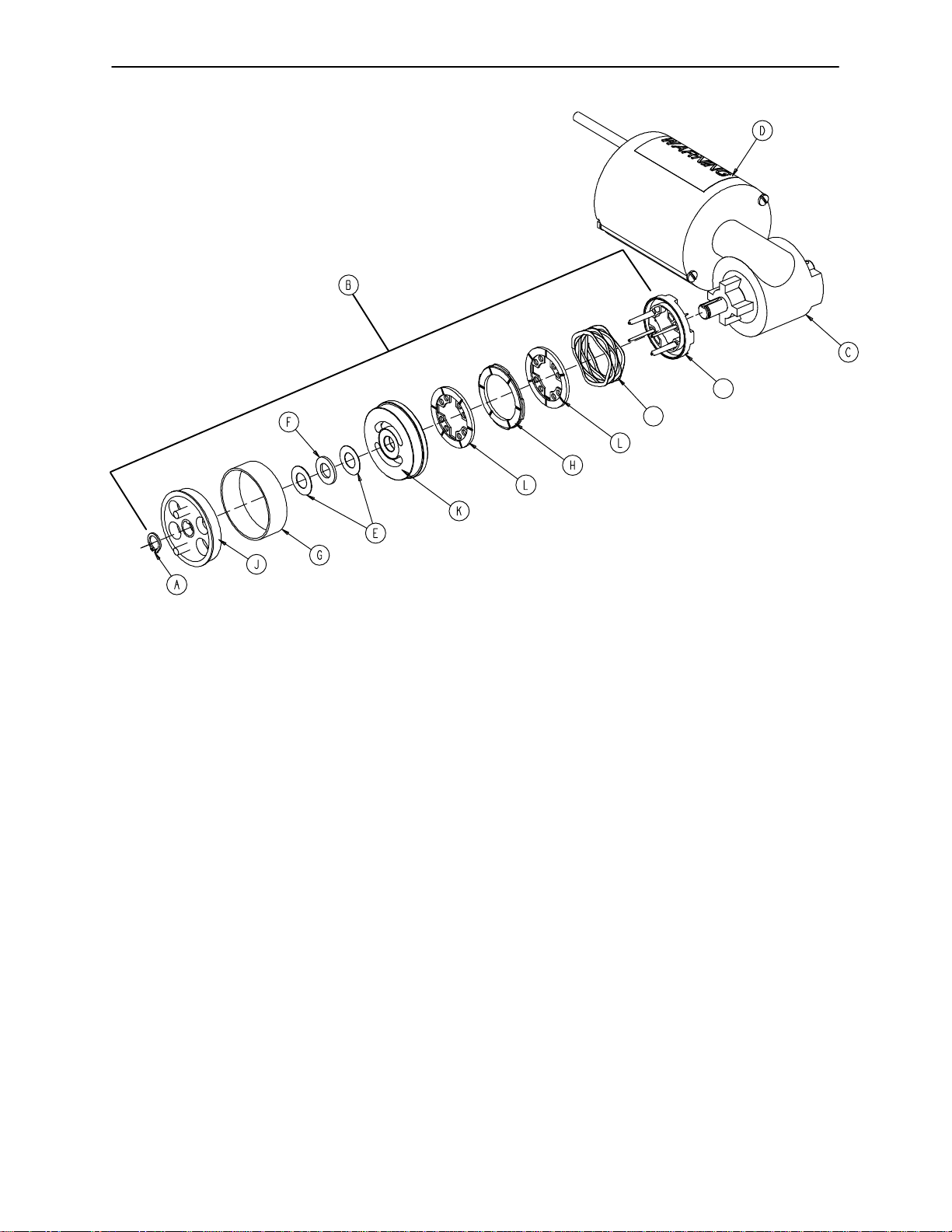
Fowler Motor/CPR Subassembly
Assembly part number 5000-30-369 (Domestic)
Assembly part number 5002-30-369 (International)
(reference only)
N
M
Item Part No. Part Name Qty.
A 28-131 Retaining Ring 1
B 3001-300-775 Brake Kit 1
C 5000-30-340 Fowler Motor 1
5002-30-340 230V Fowler Motor 1
D 3000-300-604 Warning Label 1
E 3000-200-224 Thrust Washer 2
F 81-212 Thrust Needle Roller Bearing 1
G 3000-300-465 CPR Clutch Spring 1
H 3001-300-552 Brake Disk 1
J 3001-300-455 CPR Coupler 1
K 3001-300-569 Brake Cup 1
L 3001-300-551 Brake Stator 2
M 3001-300-563 Wave Spring 1
N 3001-300-570 Spring Seat 1
54
Page 56
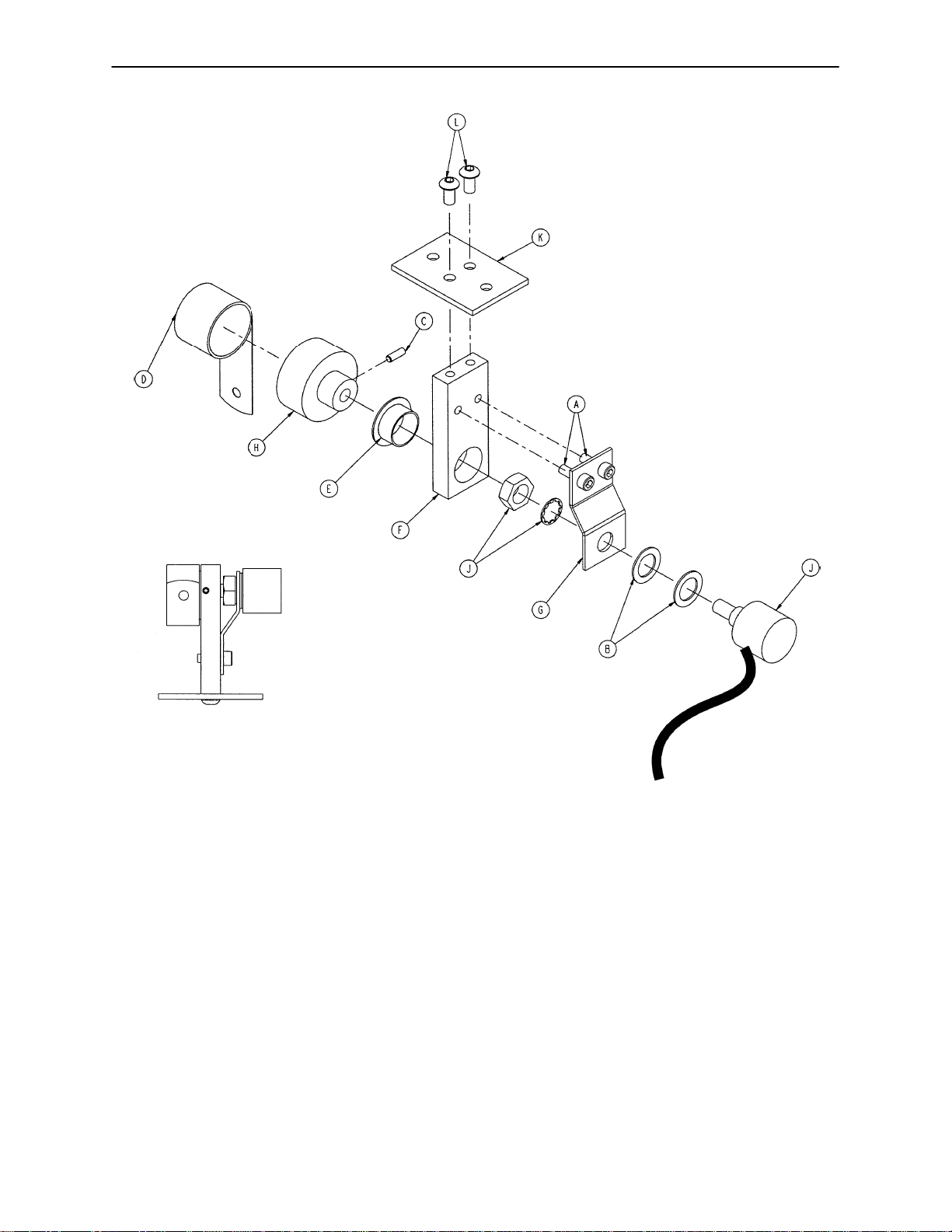
5000-30-316 Fowler Potentiometer Assembly
8.5K ohms +/-500 ohms
Pin
3 Red
4 Black
Resistance is measured between
Pin 3 Red & Pin 4 Black. Adjust
potentiometer to 8.5K ohms
+/-500 ohms.
Item Part No. Part Name Qty.
A 4-38 Soc. Hd. Cap Screw 2
B 14-8 Nylon Washer 2
C 21-149 Set Screw 1
D 38-389 Constant Force Spring 1
E 81-275 Flange Bearing 1
F 5000-30-226 Pot Mount 1
G 5000-30-227 Pot Mount Plate 1
H 5000-30-228 Drum 1
J 5000-280-7 Fowler Pot Cable 1
K 5000-30-219 Fowler Pot Bracket 1
L 4-307 But. Hd. Cap Screw 2
55
Page 57

Front Cover Assembly
Assembly part number 4700-30-40 (reference only)
56
Page 58

Front Cover Assembly
Item Part No. Part Name Qty.
A 7-58 Truss Hd. Torx 2
B 25-50 Rivet 20
C 8815-001-100 Push Mount Wire Clip 4
D 4700-30-61 Bellows, Left 1
E 4700-30-62 Bellows, Right 1
F 5010-30-21 Top Cover 1
G 5010-30-23 Top Cover Backer Plate 2
H 8800-380-000 Neoprene Sponge .33’
L 11-53 Washer 2
57
Page 59

Litter Capacitor Assembly
Assembly part numbers
5000-30-330 (Domestic)
5002-30-330 (International)
(reference only)
110V
Domestic
Assembly
230V
International
Assembly
Item Part No. Part Name Qty.
A 38-151 11” Cable Tie 4
B 5000-30-5 Capacitor Mounting Panel 1
C 8806-052-500 Adhesive Foam Tape 1.67’
58
Page 60

Non-In/Out Fowler Assembly
Assembly part number 4700-30-100 (reference only)
5010-80-13
Fowler/Trend
Limits Cable
Item Part No. Part Name Qty.
A 5010-30-101 Non-Translating Shaft 1
B 5000-80-23 Non-Fowler Slide Opt. Cable 1
C 2025-32-86 Thrust Washer 2
D 2025-32-87 Needle Thrust Bearing 1
E 26-271 Clevis Pin 2
F 14-3 Nylon Washer 6
G 27-17 Cotter Pin 1
H 27-21 Rue Ring 1
I (page 63) Square In/Out Tube Ass’y1
J 5000-30-398 Adapter Spline 1
K 45-137 O-Ring 1
59
Page 61
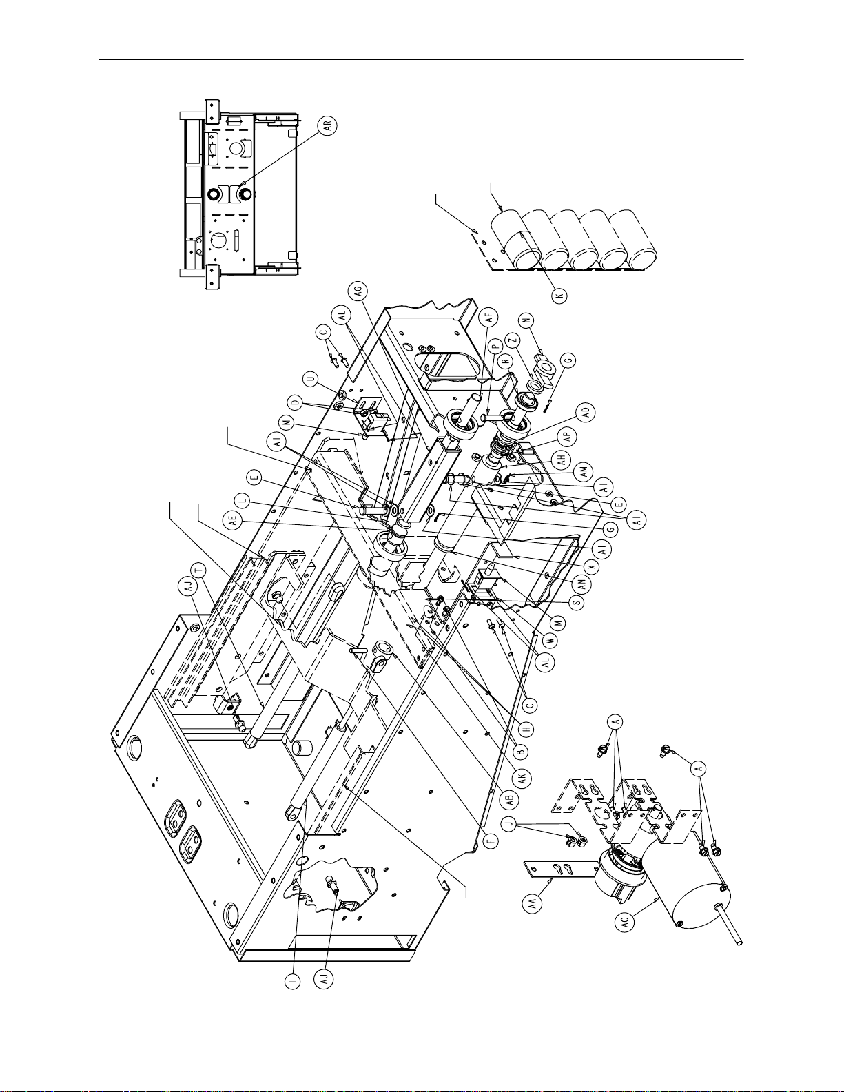
Optional Skoocher Assembly
HEAD END
Assembly part number 4700-30-85 &
4702-30-85 (230V)
(reference only)
5000-300-397
Fowler In/Out Weldment
5000-30-330
(Ref.)
Fowler In/Out
Motor Capacitor
25-30 UF
5000-30-39
Fowler Crossbrace
5000-30-25
Fowler Slide, Right
60
5000-30-24
Fowler Slide, Left
Page 62

Optional Skoocher Assembly
Item Part No. Part Name Qty.
A 3-221 Hex Washer Hd. Screw 6
B 3-224 Hex Washer Hd. Screw 2
C 4-304 Hex Soc. But. Hd. Cap Screw 4
D 16-3 Fiberlock Nut 4
E 26-271 Clevis Pin 2
F 26-168 Spiral Pin 1
G 27-17 Cotter Pin 2
H 28-120 External Retaining Ring 2
J 30-52 Snap Bushing 2
K 38-151 11” Cable Tie 1
L 45-137 O-Ring 1
M 3000-300-58 Cherry Switch 2
N 3000-300-462 CPR Wing 1
P 3000-300-473 Clevis Pin 1
R 3001-300-471 Roller Bearing 1
S 5000-30-103 Ball Screw Assembly, Left 1
T 5000-30-213 Gas Spring 2
U 5000-30-215 Fowler Out Limit Switch Bracket 1
W 5000-30-216 Fowler In Limit Switch Bracket 1
X 5000-30-221 Fowler In Trip Link Bracket 1
Z 5000-30-223 Bearing Spacer 1
AA 5000-30-252 CPR Strip Weldment 1
AB 5000-30-255 Thrust Collar 1
AC (page 53) Fowler Motor/CPR Assembly 1
AD 5000-30-289 Ball Thrust Bearing 1
AE 5000-30-398 Spline Adapter 1
AF 5000-230-86 Spline Shaft 1
AG (page 63) Square In/Out Tube Assembly 1
AH 5010-30-82 In/Out Hard Stop 1
AI 14-3 Nylon Washer 6
AJ 1550-31-2 Ball Stud Gas Spring 2
AK 8815-029-200 Cable Tie 1
AL 27-8 Cotter Pin 4
AM 27-21 Rue Ring Cotter 1
AN 5010-30-81 In/Out Hard Stop Spacer 1
AP 45-967 O-Ring 1
AR 5000-90-65 Fowler In-Out Label 1
61
Page 63

4700-30-50 Fowler Assembly
NOTE
Reference page 158 & 159 for labels.
Item Part No. Part Name Qty. Item Part No. Part Name Qty.
A 3-64 Hex Hd. Cap Screw 4 M 3000-300-3 Bumper 2
B 7-58 Truss Hd. Torx 6 N 3001-300-99 Fowler Bushing 4
C 11-376 Washer 8 P 3000-300-1 14 4” Cable Tie 4
D 13-10 External Lock Washer 12 R 3001-300-870 8” Ground Jumper 4
E 15-12 Hex Nut 2 S 4700-30-150 Fowler Weldment 1
F 16-35 Nylock Nut 4 T 4700-30-160 Left CPR Handle 1
G 25-38 Pop Rivet 10 U 4700-30-161 Right CPR Handle 1
H 25-120 Pop Rivet 4 W 5000-30-269 CPR Cable 2
J 29-3 Brass Eyelet 10 X 5000-80-24 11” Ground Jumper 2
K 29-9 Dual Lock 2 Y 8815-029-200 Cable Tie 5
L 30-52 Heyco Plug 2
62
Page 64

5000-230-89 Square In/Out Fowler Tube Assembly
Item Part No. Part Name Qty.
A 26-8 Spring Pin 2
B 5000-230-87 Square In/Out Tube 1
C 5000-230-90 Square In/Out Nut 1
63
Page 65

Litter/Lift/Trend Assembly
Assembly part number 4700-30-105 & 4702-30-105 (230V)
(reference only)
64
Page 66
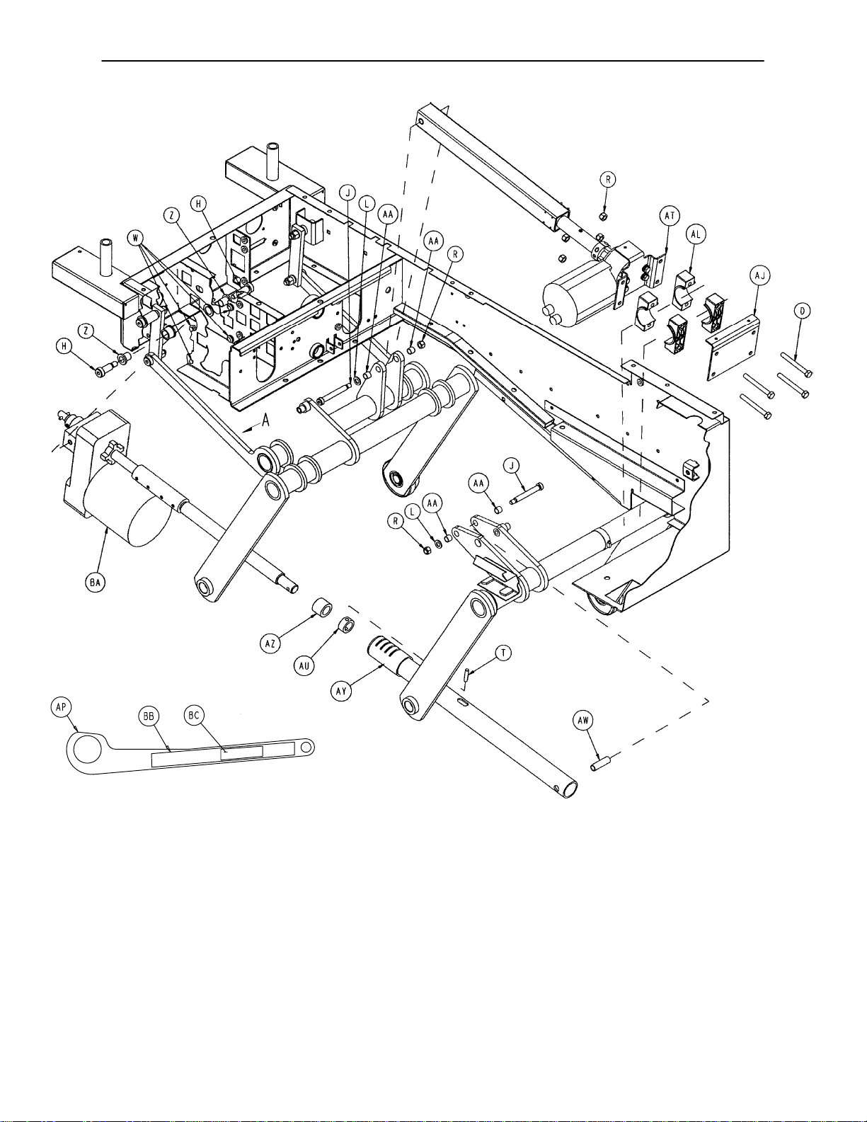
Litter/Lift/Trend Assembly
VIEW A
65
Page 67
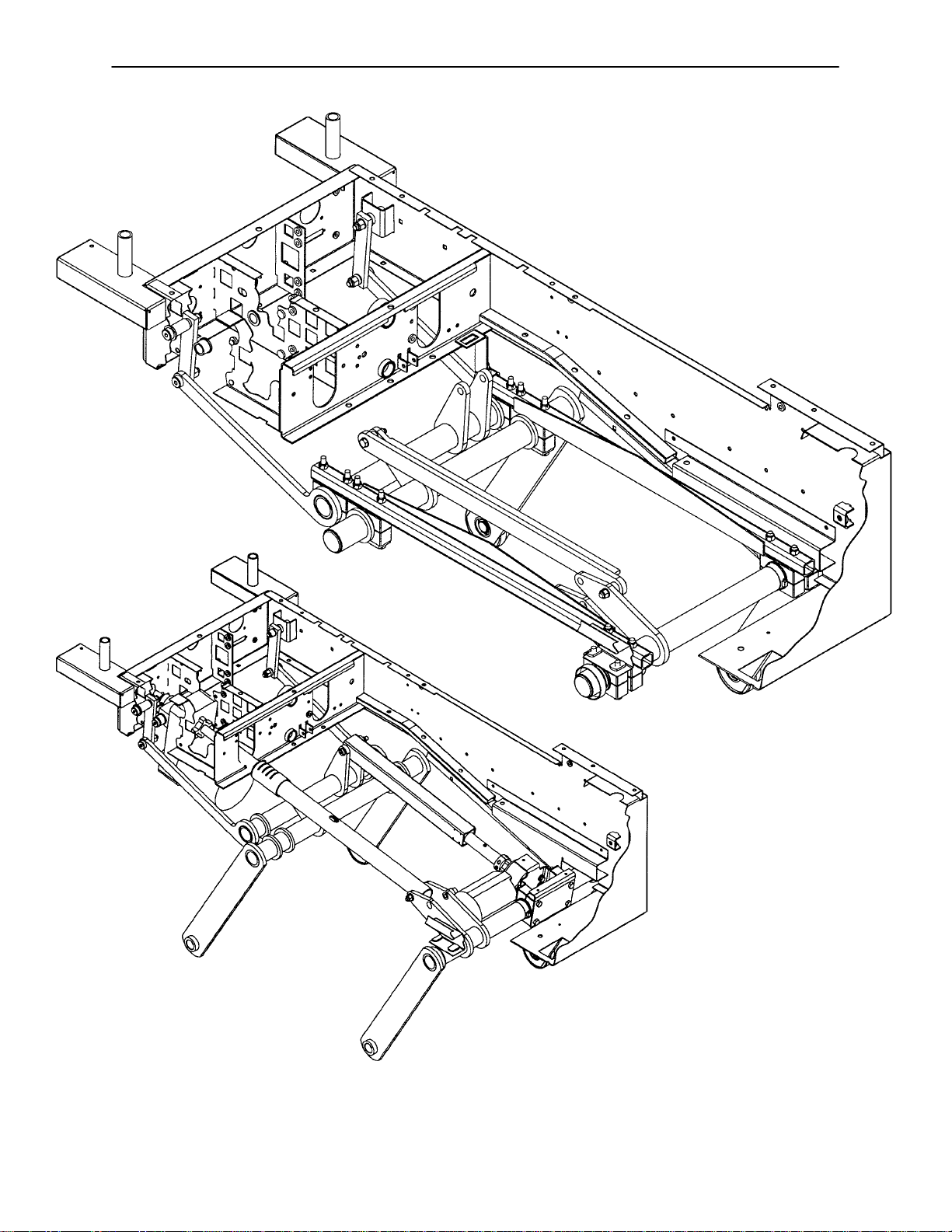
Litter/Lift/Trend Assembly
66
Page 68

Litter/Lift/Trend Assembly
Item Part No. Part Name Qty.
A 3-68 Hex Hd. Cap Screw 2
B 3-82 Hex Hd. Cap Screw 4
C 3-88 Hex Hd. Cap Screw 8
D 3-93 Hex Hd. Cap Screw 4
F 3-228 Hex Hd. Cap Screw 4
G 8-2 Hex Soc. Hd. Shoulder Bolt 2
H 8-45 Hex Soc. Hd. Shoulder Bolt 4
J 8-50 Hex Soc. Hd. Shoulder Bolt 2
K 11-3 Flat Washer 9
L 11-54 Flat Washer 6
M 11-339 Shim Washer 12
N 11-350 Flat Washer 2
P 14-7 Nylon Washer 7
R 16-11 Nylock Nut 20
S 16-35 Nylock Nut 4
T 26-280 Spiral Spring Pin 1
U 28-163 External Retaining Ring 8
W 37-52 Grommet Bumper 4
X 37-216 Round Hole Plug 4
Y 38-283 Worm Drive Hose Clamp 1
Z 81-8 Flange Bearing 2
AA 81-269 DU Bearing 4
AB 81-270 DU Bearing 4
AC 81-271 DU Bearing 8
AD 4700-30-10 Litter Weldment 1
AE 5000-1-24 Pivot Pin 4
AF 5000-30-139 Trend Block Strap 2
AG 5000-30-144 Drag Link Weldment 1
AH 5000-30-166 Trend Follower Link 2
AJ 5000-30-171 Trend Motor Mount Plate 1
AK 5000-30-222 Trend Up Link Bracket 1
AL 5000-30-237 Crank Retainer Block 20
AM 5000-30-240 Front Crank Ass’y Weldment 1
AN 5000-30-244 Rear Crank Ass’y Weldment 1
AP 5000-30-246 Trend Link Weldment 1
AR 5000-30-258 Rail Weldment, Right 1
AS 5000-30-259 Rail Weldment, Left 1
AT (page 68) Trend Actuator Assembly 1
AU 5000-30-255 Thrust Collar 1
AW 5000-30-349 Lift Tube Cross Tube 1
AX 5000-30-374 Lift Crank Cap 4
AY 5000-230-212 Lift Screw Tube 1
AZ 5010-30-69 Lift Hard Stop 1
BA (page 69) Lift Actuator Assembly 1
BB 8800-380-000 Sponge 1
BC 29-9 Dual Lock 1
67
Page 69

Assembly part numbers
5000-30-278 (Domestic)
5002-30-278 (International)
(reference only)
T rend Actuator Assembly
Item Part No. Part Name Qty.
A 3-214 Hex Hd. Cap Screw 4
B 4-90 Soc. Hd. Cap Screw 2
C 11-63 Flat Washer 12
D 21-16 Set Screw 2
F 5000-230-68 Right Angle Motor Ass’y1
5002-30-68 230V Right Angle Motor Ass’y1
G 5000-30-170 Trend Motor Mount Bracket 1
H 5000-30-286 Split Stop Collar 2
J 5000-30-312 Trend Hard Stop 1
K 26-52 Spring Pin 1
L 26-280 Spirol Pin 1
M 26-266 Spring Pin 4
N 5000-30-172 Trend Drive Tube 1
P 5000-30-208 Acme Nut 1
R 5000-30-301 Trend Spacer Tube 1
S 5000-30-372 Trend Hard Stop 1
T 3000-300-604 Warning Label 1
V 16-102 Nylock Jam Nut 2
68
Page 70
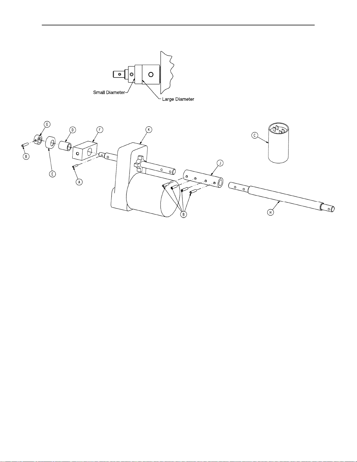
Lift Actuator Assembly
Assembly part number 5010-230-71 (Domestic)
Assembly part number 5012-30-71 (International)
Thrust Bearing Installation Detail
Item Part No. Part Name Qty.
A 26-11 Spring Pin 1
B 26-267 Spring Pin 5
C 59-140 Capacitor 1
3221-300-453 230V Capacitor 1
D 81-9 Bronze Bearing 1
E 81-276 Thrust Ball Bearing 1
F 5000-30-194 Motor Pivot Block 1
G 5000-30-255 Thrust Collar 1
H 5000-30-379 Lift Screw 1
J 5000-30-380 Lift Coupler 1
K 5000-30-381 Lift Motor Assembly 1
5012-230-70 230V Lift Motor Assembly 1
69
Page 71
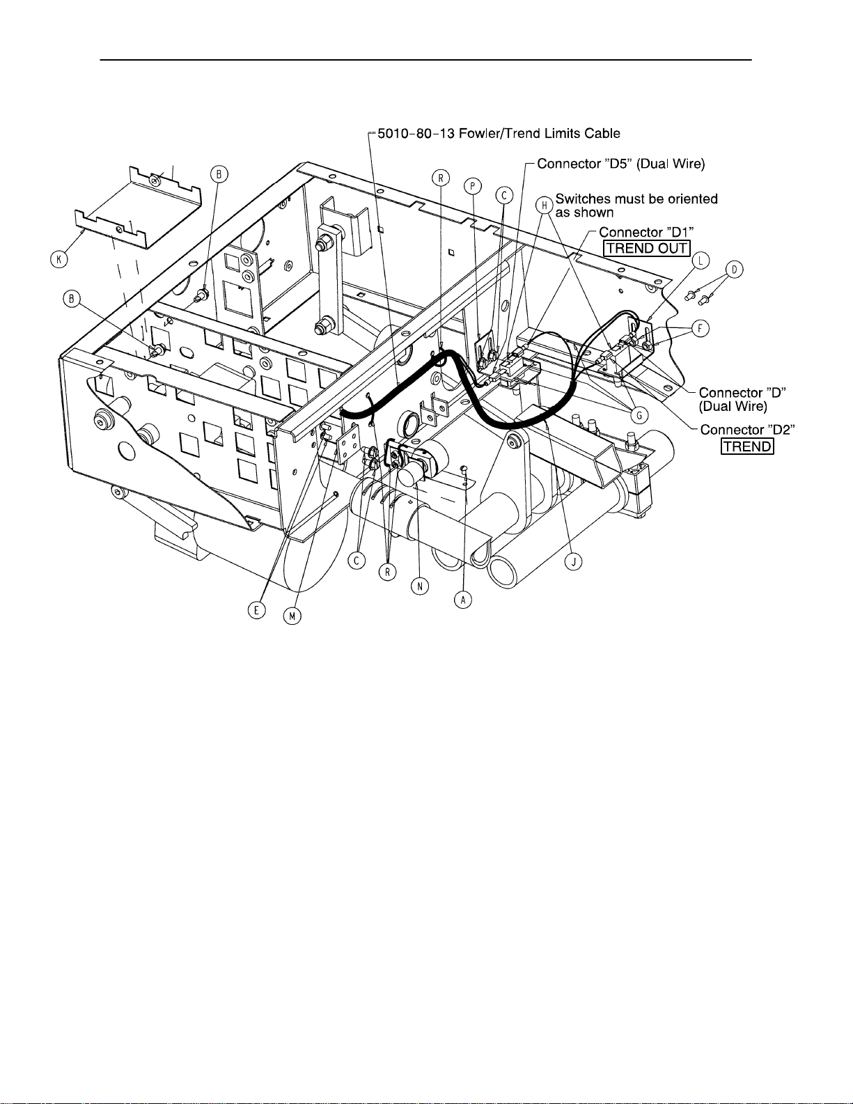
Bed Lift/Trend Limits Assembly
Assembly part number
4700-30-110 (reference only)
Item Part No. Part Name Qty.
A 2-34 Round Hd. Mach. Screw 1
B 3-221 Hex Washer Hd. Screw 2
C 3-224 Hex Washer Hd/ Screw 4
D 4-304 Hex Soc. But. Hd. Cap Screw 2
E 4-307 But. Hd. Cap Screw 2
F 16-3 Fiberlock Nut 2
G 27-8 Cotter Pin 4
H 3000-300-58 Limit Switch 2
J 3000-300-1 14 4” Cable Tie 1
K 4700-30-18 Filter Shield Weldment 1
L 5000-30-217 Trend Limit Switch Bracket 1
M 5000-30-220 Lift Motor Pot Bracket 1
N (page 71) Bed Lift Potentiometer Ass’y1
P 5000-30-341 Trend Up Trip Bracket 1
R 8815-029-200 7.4” Cable Tie 4
70
Page 72

5000-30-225 Bed Lift Potentiometer Assembly
5.8K ohms +/-500 ohms
Pin
2 Green
3 Red
Resistance is measured between
Pin 2 Green & Pin 3 Red. Adjust
potentiometer to 5.8K ohms
+/-500 ohms.
Item Part No. Part Name Qty.
A 4-38 Soc. Hd. Cap Screw 2
B 14-8 Nylon Washer 2
C 21-149 Set Screw 1
D 38-389 Constant Force Spring 1
E 81-275 Flange Bearing 1
F 5000-30-226 Pot Mount 1
G 5000-30-227 Pot Mount Plate 1
H 5000-30-228 Drum 1
J 5000-280-6 Bed Up/Down Pot Cable 1
71
Page 73

Assembly part numbers
4700-30-65 &
4702-30-65 (230V)
(reference only)
Foot Lift Assembly
72
Page 74

Foot Lift Assembly
Item Part No. Part Name Qty.
A 3-214 Hex Hd. Cap Screw 4
B 11-63 Washer 2
C 26-267 Spring Pin 1
D 4700-30-25 Foot Lift Lock Plate 1
E 52-718 Nylon Insulator 4
F 3000-200-228 Motor Mounting Plate Grommet 4
G 4700-30-36 Foot Lift Shaft 2
H 5000-230-68 Right Angle Motor Ass’y1
5002-30-68 230V Right Angle Motor Ass’y1
J 5000-30-208 Acme Nut 1
K 5000-30-21 1 Foot Tube Weldment 1
L 8800-200-700 Retaining Ring 2
M 8800-210-400 Split Tube Bushing 4
N 8812-400-100 Bushing Housing 2
P 5000-30-286 Split Stop Collar 2
R 4-90 Soc. Hd. Cap Screw 2
S 5000-30-327 Foot Lift Manual Nut 1
T (page 74) Foot Pot Assembly 1
U 7-58 Truss Hd. Torx 2
W 3-224 Hex Washer Hd. Screw 1
X 4-307 Hex Soc. But. Hd. Cap Screw 2
Y 5000-230-284 Foot Motor Shroud 1
Z 8800-380-000 Sponge .167’
AA 13-10 External Tooth Lock Washer 2
AB 26-52 Spring Pin 1
AC 3000-300-604 Warning Label 1
AD 8815-029-200 Cable Tie 2
AE 16-102 Nylock Jam Nut 2
AF 3-76 Hex Hd. Cap Screw 2
AG 11-224 Nylon Washer 4
73
Page 75
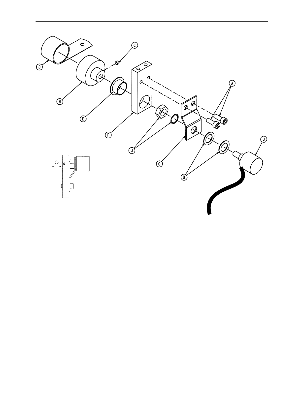
5000-30-317 Foot Potentiometer Assembly
4.0K ohms +/-500 ohms
Pin
2 Green
3 Red
Resistance is measured between
Pin 2 Green & Pin 3 Red. Adjust
potentiometer to 4.0K ohms
+/-500 ohms.
Item Part No. Part Name Qty.
A 4-38 Soc. Hd. Cap Screw 2
B 14-8 Nylon Washer 2
C 21-149 Set Screw 1
D 38-389 Constant Force Spring 1
E 81-275 Flange Bearing 1
F 5000-30-226 Pot Mount 1
G 5000-30-227 Pot Mount Plate 1
H 5000-30-228 Drum 1
J 5000-80-5 Foot Pot Cable 1
74
Page 76

Assembly part number 5010-30-17
(reference only)
Seat Assembly
Item Part No. Part Name Qty.
A 4-161 But. Hd. Cap Screw 8
B 7-58 Torx Hd. Screw 6
C 16-28 Nylock Nut 8
D 25-38 Rivet 5
E 29-3 Brass Eyelet 5
F (page 76) Hand Grip Ass’y, Right 1
G (page 77) Hand Grip Ass’y, Left 1
H 5010-30-19 Seat Weldment 1
75
Page 77

Right Hand Grip Assembly
Assembly part number 5010-230-60 (reference only)
NOTE
Reference page 158 & 159 for label.
Item Part No. Part Name Qty.
A 3-32 Hex Hd. Cap Screw 1
B 3-57 Hex Hd. Cap Screw 1
C 3-73 Hex Hd. Cap Screw 1
D 4-5 Soc. Hd. Cap Screw 2
E 11-179 Nylon Washer 2
F 11-392 Nylon Washer 2
G 11-397 Serrated Belleville Washer 1
H 11-406 Flat Washer 1
J 16-14 Nylock Nut 2
K 16-28 Nylock Nut 2
L 38-344 Compression Spring 1
M 38-391 Compression Spring 1
N 5000-30-124 Pivot Block, Right 1
P 5000-30-128 Hand Grip Lock Pin 1
R 5000-30-129 Hand Grip Latch Bracket 1
S 5000-30-315 Hand Grip Spring Spacer 1
T 5000-40-1 18 Pull Handle 1
U 5010-230-62 Hand Grip Weldment, Rt. 1
76
Page 78

Left Hand Grip Assembly
NOTE
Reference page 158 & 159 for label.
Assembly part number 5010-230-61 (reference only)
Item Part No. Part Name Qty.
A 3-32 Hex Hd. Cap Screw 1
B 3-57 Hex Hd. Cap Screw 1
C 3-73 Hex Hd. Cap Screw 1
D 4-5 Soc. Hd. Cap Screw 2
E 11-179 Nylon Washer 2
F 11-392 Nylon Washer 2
G 11-397 Serrated Belleville Washer 1
H 11-406 Flat Washer 1
J 16-14 Nylock Nut 2
K 16-28 Nylock Nut 2
L 38-344 Compression Spring 1
M 38-391 Compression Spring 1
N 5000-30-125 Pivot Block, Left 1
P 5000-30-128 Hand Grip Lock Pin 1
R 5000-30-129 Hand Grip Latch Bracket 1
S 5000-30-315 Hand Grip Spring Spacer 1
T 5000-40-1 18 Pull Handle 1
U 5010-230-63 Hand Grip Weldment, Lt. 1
77
Page 79

Glideaway Foot Support Assembly
Assembly part number 4700-440
(reference only)
Item Part No. Part Name Qty.
A 3-229 Hex Hd. Cap Screw 4
B (page 80 & 81) Foot Mattress Assembly 1
C (page 82) Left Upright Assembly 1
D (page 83) Right Upright Assembly 1
E (page 84) Left Glideaway Assembly 1
F (page 85) Right Glideaway Assembly 1
78
Page 80

Notes
79
Page 81
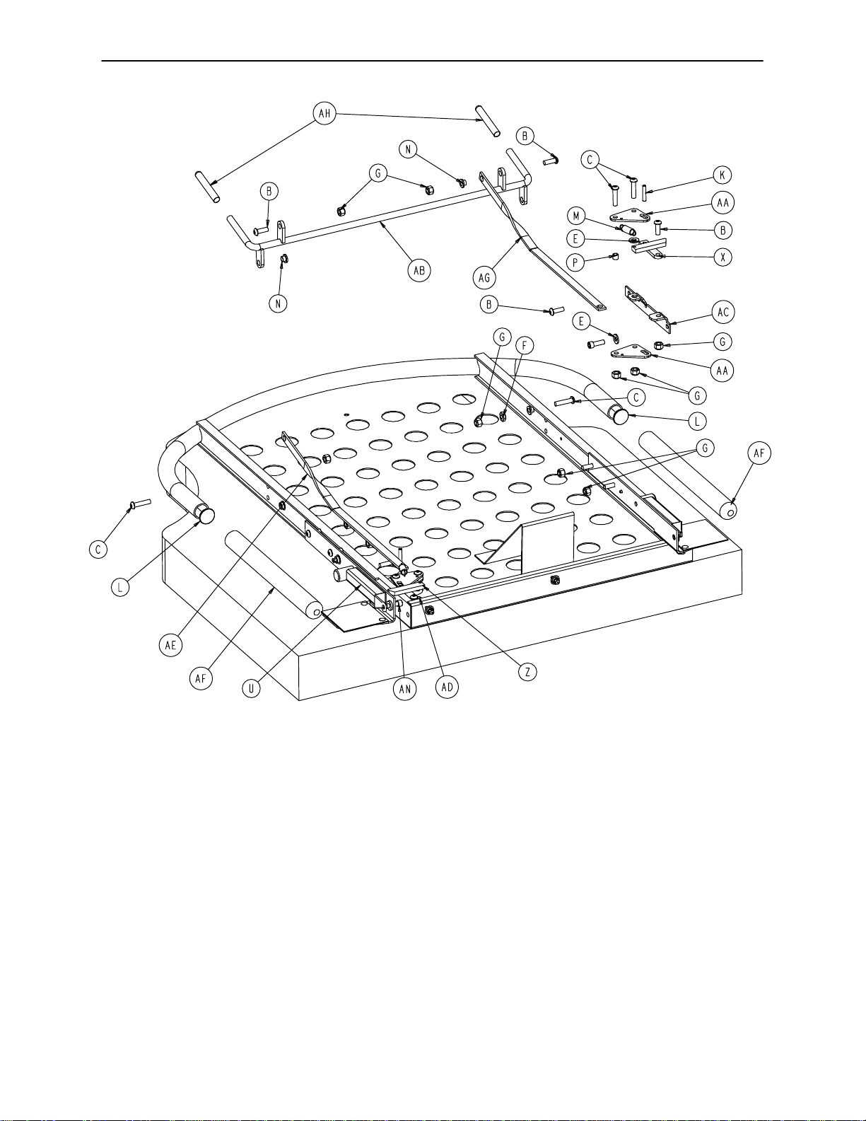
4700-40-70 Slide-Off Foot Mattress Assembly
Item Part No. Part Name Qty. Item Part No. Part Name Qty.
A 25-151 Semi-T ubular Rivet 4 U 5000-40-96 Pilot Weldment, Right 1
B 4-161 But. Hd. Cap Screw 10 X 5000-40-135 Latch Weldment, Left 1
C 4-176 But. Hd. Cap Screw 6 Z 5000-40-136 Latch Weldment, Right 1
D 4-232 But. Hd. Cap Screw 3 AA 5000-40-139 Pull Plate 4
E 11-63 Flat Washer 4 AB 5000-40-140 Trip Handle Weldment 1
F 15-11 Jam Nut 2 AC 5000-40-143 Pivot, Right 1
G 16-28 Nylock Nut 17 AD 5000-40-144 Pivot, Left 1
H 25-40 Pop Rivet 3 AE 5000-40-150 Handle Pull 2
J 26-1 1 Spring Pin 2 AF 4700-40-5 Foot Section End Cap 2
K 29-3 Brass Eyelet 4 AG 5000-40-168 Kickstand 1
L 37-62 Hole Plug 2 AH 5000-40-200 Vinyl Cap 2
M 38-330 Extension Spring 2 AJ 4700-41-000 Foot Mattress 1
N 52-718 Nylon Insulator 4 AK 5000-40-227 Plastic Plate, Left 1
P 715-1-133 Release Rod Stop Sleeve 2 AL 5000-40-228 Plastic Plate, Right 1
R 4700-40-10 Foot Mattress Weldment 1 AM 25-170 Pop Rivet 4
S 5000-40-88 Round Stop 2 AN 4-556 H. Soc. Hd. Cap Screw 2
T 5000-40-95 Pilot Weldment, Left 1
80
Page 82

4700-40-70 Slide-Off Foot Mattress Assembly
81
Page 83
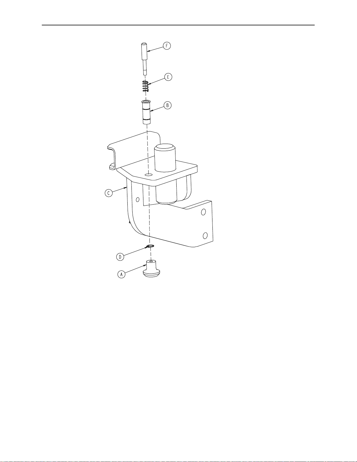
Left Upright Assembly
Assembly part number
4700−440−132
(reference only)
Item Part No. Part Name Qty.
A 5010−40−71 Pull Knob 1
B 5000−40−134 Latch Pin Sleeve 1
C 4700−440−10 Left Upright Weldment 1
D 8800−201−100 Retaining Ring 1
E 8810−290−600 Compression Spring 1
F 8813−070−100 Foot Latch Pin 1
82
Page 84

Right Upright Assembly
Assembly part number
4700−440−133
(reference only)
Item Part No. Part Name Qty.
A 5010−40−71 Pull Knob 1
B 5000−40−134 Latch Pin Sleeve 1
C 4700−440−11 Right Upright Weldment 1
D 8800−201−100 Retaining Ring 1
E 8810−290−600 Compression Spring 1
F 8813−070−100 Foot Latch Pin 1
83
Page 85

Assembly part number
5010-340-21
(reference only)
Left Glideaway Assembly
Item Part No. Part Name Qty.
A 4-178 But. Hd. Cap Screw 4
B 4-320 But. Hd. Cap Screw 4
C 11-343 Shim Washer 2
D 11-411 Washer 1
E 28-166 External Retaining Ring 1
F 37-220 Hole Plug 1
G 81-289 I-Glide Bearing 2
H 5010-40-39 Keyhole Plate 1
J (page 86) Left Foot Pan Assembly 1
K 5010-240-25 Left Foot Rest 1
L (page 88 & 89) Left Link Assembly 1
84
Page 86

Right Glideaway Assembly
Assembly part number 5010-340-22 (reference only)
Item Part No. Part Name Qty.
A 4-178 But. Hd. Cap Screw 4
B 4-320 But. Hd. Cap Screw 4
C 11-343 Shim Washer 2
D 11-411 Washer 1
E 28-166 External Retaining Ring 1
F 37-220 Hole Plug 1
G 81-289 I-Glide Bearing 2
H 5010-40-39 Keyhole Plate 1
J (page 87) Right Foot Pan Assembly 1
K 5010-240-26 Right Foot Rest 1
M (page 90 & 91) Right Link Assembly 1
85
Page 87

5010-40-59 Left Foot Pan Assembly
Item Part No. Part Name Qty. Item Part No. Part Name Qty.
A 4-42 Soc. Hd. Cap Screw 1 N 5000-90-44 “Pull” Label 1
B 4-178 But. Hd. Cap Screw 2 P 5010-40-27 Slide Weldment 1
C 23-1 Pan Hd. Thread Cutting Scr. 8 R 5010-40-35 Pan Bottom 1
D 4-337 But. Hd. Cap Screw 1 S 5010-40-37 Slide Top 1
E 16-7 Nylock Nut 1 T 5010-40-38 Pull Handle 1
F 16-36 Nylock Nut 2 U 5010-40-41 Pan End Cap 1
G 16-28 Fiberlock Hex Nut 1 V 5010-40-55 Locking Plate 1
H 23-260 Pan Hd. Hi-Lo Tapping Scr. 11 W 5010-40-57 Pan Weldment, Left 1
J 28-166 External Retaining Ring 1 X 5010-240-34 Slide 2
K 38-387 Compression Spring 1 Z 5010-90-2 Glideaway Label, Left 1
L 5000-40-32 Square Latch Housing 1 AA 8800-210-400 Split Tube Bushing 1
M 5000-40-37 Square Latch Pin 1
86
Page 88

5010-40-58 Right Foot Pan Assembly
Item Part No. Part Name Qty. Item Part No. Part Name Qty.
A 4-42 Soc. Hd. Cap Screw 1 N 5000-90-44 “Pull” Label 1
B 4-178 But. Hd. Cap Screw 2 P 5010-40-27 Slide Weldment 1
C 23-1 Pan Hd. Thread Cutting Scr. 8 R 5010-40-35 Pan Bottom 1
D 4-337 But. Hd. Cap Screw 1 S 5010-40-37 Slide Top 1
E 16-7 Nylock Nut 1 T 5010-40-38 Pull Handle 1
F 16-36 Nylock Nut 2 U 5010-40-41 Pan End Cap 1
G 16-28 Fiberlock Hex Nut 1 V 5010-40-55 Locking Plate 1
H 23-260 Pan Hd. Hi-Lo Tapping Scr. 11 W 5010-40-56 Pan Weldment, Right 1
J 28-166 External Retaining Ring 1 X 5010-240-34 Slide 2
K 38-387 Compression Spring 1 Z 5010-90-3 Glideaway Label, Right 1
L 5000-40-32 Square Latch Housing 1 AA 8800-210-400 Split Tube Bushing 1
M 5000-40-37 Square Latch Pin 1
87
Page 89
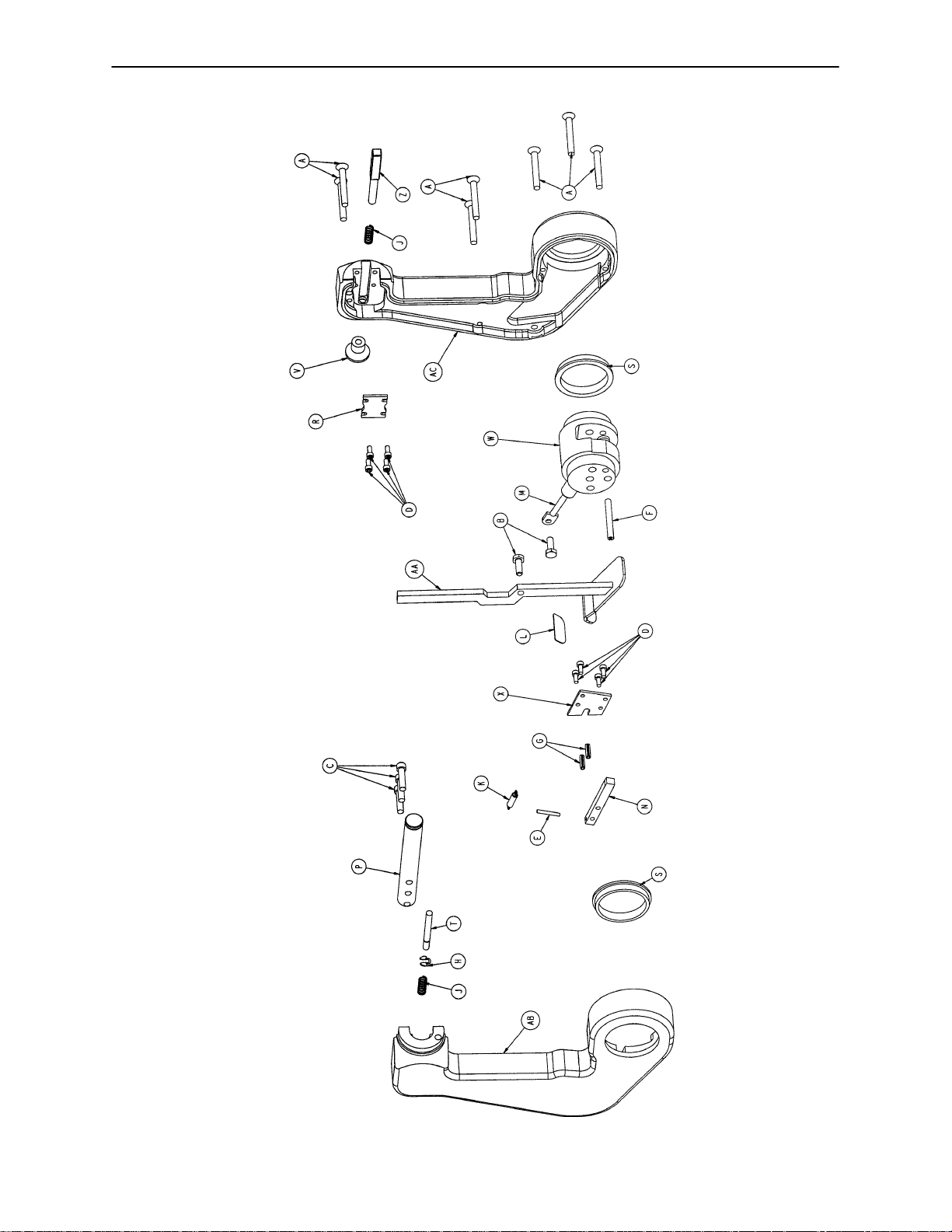
Glideaway Link Assembly, Left
Assembly part number 5010-340-7 (reference only)
88
Page 90

Glideaway Link Assembly, Left
Item Part No. Part Name Qty.
A 1-124 Flat Hd. Machine Screw 7
B 3-214 Hex Hd. Cap Screw 2
C 4-28 Soc. Hd. Cap Screw 3
D 4-316 Soc. Hd. Cap Screw 8
E 26-7 Roll Pin 1
F 26-45 Roll Pin 2
G 26-172 Roll Pin 2
H 28-183 Retaining Ring 1
J 38-110 Compression Spring 2
K 38-274 Extension Spring 1
L 5000-90-19 Pull Label 1
M 5010-40-10 Gas Spring 1
N 5010-40-1 1 Lower Latch Pin 1
P 5010-40-13 Flipper Pivot 1
R 5010-40-14 Upper Retainer 1
S 5010-40-16 Bearing 2
T 5010-40-17 Lock Pin 1
V 5010-40-52 Flipper Pull Knob 1
W 5010-240-9 Center Casting 1
X 5010-240-12 Small Retainer 1
Z 5010-240-15 Flipper Pin 1
AA 5010-240-47 Pull Handle Weldment 1
AB 5010-340-3 Left Link Half, Foot End 1
AC 5010-340-4 Left Link Half, Head End 1
89
Page 91

Glideaway Link Assembly, Right
Assembly part number 5010-340-8 (reference only)
90
Page 92

Glideaway Link Assembly, Right
Item Part No. Part Name Qty.
A 1-124 Flat Hd. Machine Screw 7
B 3-214 Hex Hd. Cap Screw 2
C 4-28 Soc. Hd. Cap Screw 3
D 4-316 Soc. Hd. Cap Screw 8
E 26-7 Roll Pin 1
F 26-45 Roll Pin 1
G 26-172 Roll Pin 2
H 28-183 Retaining Ring 1
J 38-110 Compression Spring 2
K 38-274 Extension Spring 1
L 5000-90-19 Pull Label 1
M 5010-40-10 Gas Spring 1
N 5010-40-1 1 Lower Latch Pin 1
P 5010-40-13 Flipper Pivot 1
R 5010-40-14 Upper Retainer 1
S 5010-40-16 Glide-Away Bearing 2
T 5010-40-17 Lock Pin 1
V 5010-40-52 Flipper Pull Knob 1
W 5010-240-9 Center Casting 1
X 5010-240-12 Small Retainer 1
Z 5010-240-15 Flipper Pin 1
AA 5010-240-47 Pull Handle Weldment 1
AB 5010-340-5 Right Link Half, Foot End 1
AC 5010-340-6 Right Link Half, Head End 1
91
Page 93

Electrical Assembly
Assembly part number 4700-30-80 (reference only)
4700-700-3 CPU (NO HEADWALL INTERFACE)
4700-700-4 CPU (WITH HEADWALL INTERFACE)
92
Page 94

5010-080-008
CABLE, HEADWALL INTERFACE
5010-080-020
CABLE, 9V BATTERY BOX
5000-280-007
FOWLER POT CABLE
Electrical Assembly
5010-080-018
NIGHT LIGHT CABLE
5010-080-019
CABLE, PENDANT PORT OPTION
5000-080-005
FOOT POT CABLE
TREND LIFT
5000-280-006
BED UP/DOWN
POT CABLE
FOWLER MOTOR
5000-230-300
MANIFOLD ASS’Y
5002-030-300 230V
MANIFOLD ASS’Y
FOWLER SLIDE MOTOR
5000-080-004
BOARD CABLE
OPTION POWER
OR 2035-001-810
SNUBBER CABLE
FOOT LIFT
ITEM ”AC” CABLE
ROUTED UNDER CPU
LIFT M O TOR
5000-080-021
5000-080-004
93
5010-080-009
COMPRESSOR CABLE
CPU OPTION POWER
CABLE, HWI
5010-080-008
BOARD CABLE
5010-080-019
PENDANT PORT
CABLE
WHITE, SINGLE WIRE, FAST ON
WHITE, DOUBLE WIRE, FASTON
BLACK, SINGLE WIRE, FASTON
BLACK, DOUBLE WIRE, FASTON
Page 95

Electrical Assembly
Item Part No. Part Name Qty.
A 2-41 Round Hd. Mach. Screw 2
B 3-221 Hex Washer Hd. Screw 2
C 3-226 Hex Washer Hd. Screw 4
D 7-58 Truss Hd. Torx 6
E 13-10 External Tooth Lock Washer 12
F 13-38 External Tooth Lock Washer 1
G 16-23 Nylock Nut 2
H 16-33 Kep Nut 2
J 4700-30-26 Top Cover 1
K 59-136 Push Mount Wire Clip 2
L 59-137 Shunt 2
M 59-149 6A Fuse 2
N 59-157 Power Supply 1
P 59-171 Push Spacer 2
R 2011-1-215 Grounding Lug 1
S 2020-2-664 Fuse Holder 2
T 3000-300-1 14 Cable Tie 1
U 3000-300-1 15 Standoff 9
W 3001-300-7 Jack Screw 4
X 5010-80-13 Fowler/Trend. Limits Cable 1
Z 4700-30-108 Service Shelf Panel 1
AA 4700-30-109 Circuit Boards Cover 1
AB 4700-30-272 Inner Panel Cover 1
AC 5010-80-1 Siderail Extension Cable 1
AD 4700-80-2 Inlet/CPU Ground Cable 1
AE 5010-80-3 CPU/Power Supply Cable 1
AF 4700-80-4 Power Inlet Cable 1
AG 5010-80-10 Power Junction Cable 1
AH 8800-380-000 Sponge 1.51’
AI 8815-029-200 Cable Tie 5
AJ 13-37 Int. Tooth Lock Washer 2
AK 5010-80-7 Power Supply Ground Cable 1
AL 5010-30-77 Fuse Cover 1
AM 4-307 Hex Soc. But. Hd. Cap Screw 2
AN 7000-1-326 Sealing Tape 8.33’
AP 4-320 But. Hd. Cap Screw 1
AR 34-22 Cord Clamp 1
AS 59-135 Push Mount Wire Clip 1
94
Page 96
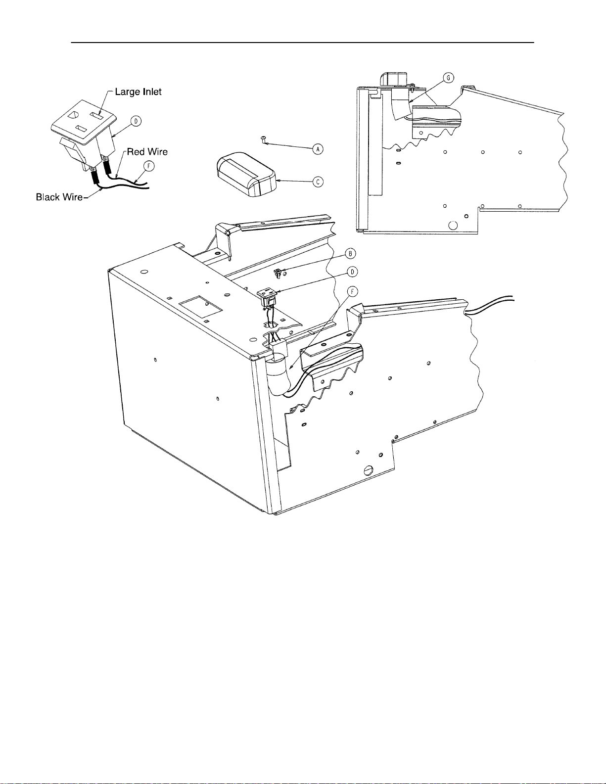
5010-30-75 Night Light Assembly
BOTTOM VIEW
FOOT END
Item Part No. Part Name Qty.
A 8815-002-200 Pan Hd. Screw 1
B 52-816 Grommet 1
C 59-160 Night Light 1
D 59-166 AC Socket 1
F 5010-80-18 Night Light Cable 1
G 7000-1-327 PVC Tubing .33’
95
Page 97

No Head Wall Interface Assembly
Assembly part number 4700-30-94 (reference only)
Item Part No. Part Name Qty.
A 4-307 Hex Soc. But. Hd. Cap Screw 4
B 59-137 Shunt 1
C 3001-300-970* CPU, No Head Wall, No Scale 1
D 5000-30-367 No Head Wall Plate 1
E 4700-440-100 Eprom Assembly 1
NOTE
Items C & E are shown on assembly number 4700-30-80 (Electrical Assembly page 92-94)
* CPU Kit - 4700-700-3
96
Page 98
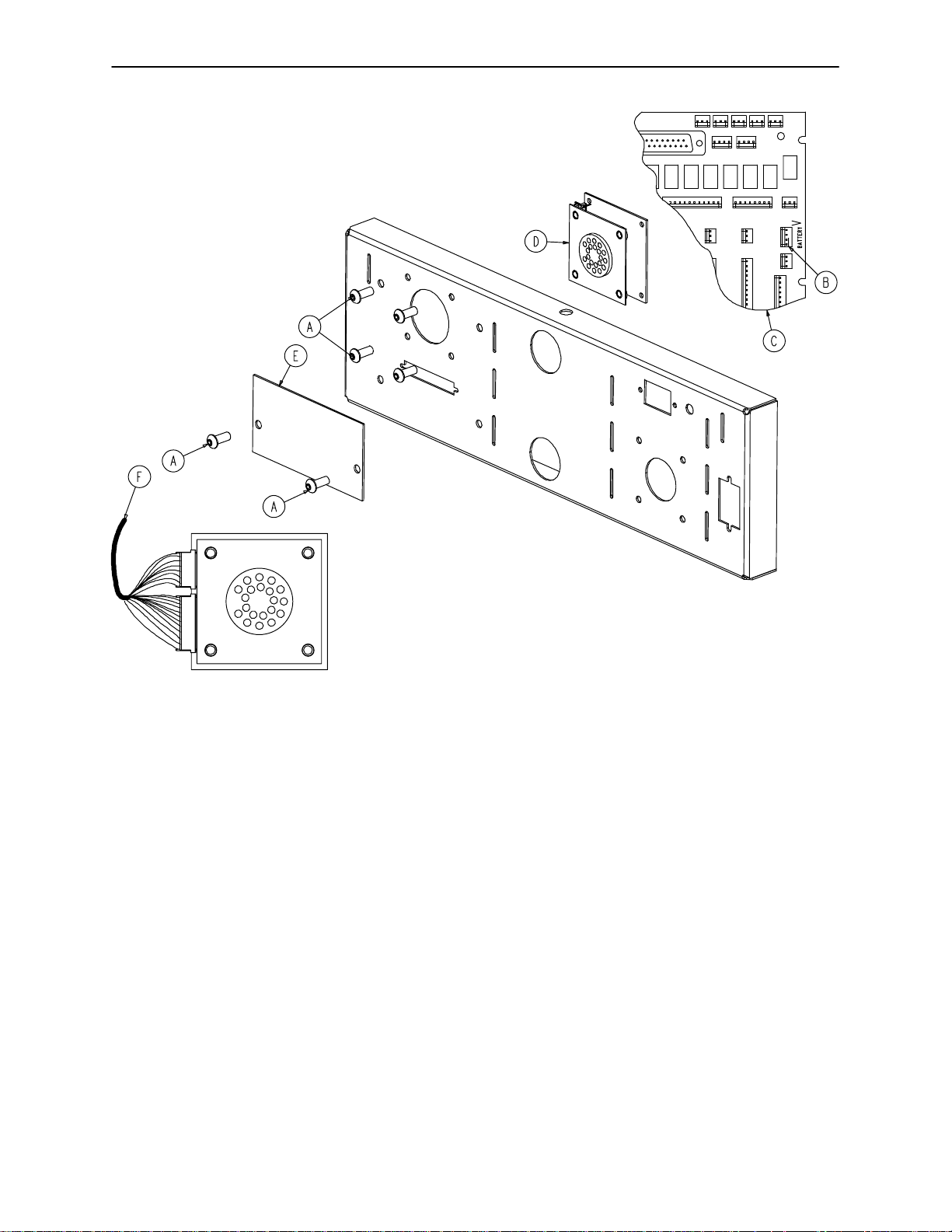
4700-30-92 Pendant Port/No Nurse Call Assembly
Item Part No. Part Name Qty.
A 4-307 Hex Soc. But. Hd. Cap Screw 6
B 59-137 Shunt 1
C 3001-303-964* Head Wall CPU, Non-Scale 1
D 3001-314-920 Pendant Port PCB Ass’y1
E 5010-30-1 Cover Panel 1
F 5010-80-19 Pendant Port Option Cable 1
G 4700-440-100 Eprom Assembly 1
NOTE
Items C & G are shown on assembly number 4700-30-80 (Electrical Assembly page 92-94)
* CPU Kit - 4700-700-4
97
Page 99

4700-30-93 Head Wall Interface - Nurse Call/No Port
Item Part No. Part Name Qty.
A 1-87 Flat Hd. Ctr. Sk. Mach. Screw 2
B 4-307 Hex Soc. But. Hd. Cap Screw 2
C 52-783 Speed Nut 2
D 59-710 Static Plug 1
E 3001-300-7 Jack Screw 2
F 3001-303-964* Head Wall CPU, Non-Scale 1
G 5010-30-1 Cover Panel 1
H 5010-80-8 Head Wall Interface Cable 1
J 5010-80-20 9V Battery Box Cable 1
K 4700-440-100 Eprom Assembly 1
NOTE
Items F & K are shown on assembly number 4700-30-80 (Electrical Assembly page 92-94)
* CPU Kit - 4700-700-4
98
Page 100

4700-30-91 Head Wall Interface - Nurse Call/Comm.
HEAD END VIEW
Item Part No. Part Name Qty.
A 1-87 Flat Hd. Ctr. Sk. Mach. Screw 2
B 4-307 Hex Soc. But. Hd. Cap Screw 4
C 52-783 Speed Nut 2
D 59-710 Static Plug 1
E 3001-300-7 Jack Screw 2
F 3001-303-964* Head Wall CPU, Non-Scale 1
G 3001-314-920 Pendant Port PCB Ass’y1
H 5010-80-8 Head Wall Interface Cable 1
J 5010-80-19 Pendant Port Option Cable 1
K 5010-80-20 9V Battery Box Cable 1
L 4700-440-100 Eprom Assembly 1
M 5000-90-28 HWI Port Label 1
NOTE
Items F & L are shown on assembly number 4700-30-80 (Electrical Assembly page 92-94)
* CPU Kit - 4700-700-4
99
 Loading...