

Page 1

IMPORTANT
File in your
maintenance
records
916 Gurney
920/921 Instacare
930/931 Constacare
935 Surgicare
936 Surgicare
937 Surgicare
960 SurgiBed
r Stretcher
r Transport Stretcher
r Transport Stretcher
r
r Stretcher
R Stretcher
962 Taper Head SurgiBedr
MAINTENANCE MANUAL
For Parts or Technical Assistance:
1–800–327–0770
Page 2

Table of Contents
SERVICE INFORMATION
Cleaning 3. . . . . . . . . . . . . . . . . . . . . . . . . . . . . . . . . . . . . . . . . . . . . . . . . . . . . . . . . . . . . . . . . . . . . . . . . . . . . . . .
Preventative Maintenance Checklist 4. . . . . . . . . . . . . . . . . . . . . . . . . . . . . . . . . . . . . . . . . . . . . . . . . . . . . . . .
Hydraulic System Troubleshooting 5. . . . . . . . . . . . . . . . . . . . . . . . . . . . . . . . . . . . . . . . . . . . . . . . . . . . . . . . . .
Checking Hydraulic Fluid Level 6. . . . . . . . . . . . . . . . . . . . . . . . . . . . . . . . . . . . . . . . . . . . . . . . . . . . . . . . . . . . .
ASSEMBLY DRAWINGS AND PARTS LISTS
Base Assembly (with Carpet Wheels) 7. . . . . . . . . . . . . . . . . . . . . . . . . . . . . . . . . . . . . . . . . . . . . . . . . . . . . . .
Base Assembly (with Foot Control Jacks) 8, 9. . . . . . . . . . . . . . . . . . . . . . . . . . . . . . . . . . . . . . . . . . . . . . . . . .
Jack Assembly 10, 11. . . . . . . . . . . . . . . . . . . . . . . . . . . . . . . . . . . . . . . . . . . . . . . . . . . . . . . . . . . . . . . . . . . . . . .
Base Assembly (with Low Foot Control Jacks) 12, 13. . . . . . . . . . . . . . . . . . . . . . . . . . . . . . . . . . . . . . . . . . .
Jack Assembly, Low 14, 15. . . . . . . . . . . . . . . . . . . . . . . . . . . . . . . . . . . . . . . . . . . . . . . . . . . . . . . . . . . . . . . . . .
Base Assembly (with Hand Control Jacks) 16, 17. . . . . . . . . . . . . . . . . . . . . . . . . . . . . . . . . . . . . . . . . . . . . . .
Jack Assembly, Hand Control 18, 19. . . . . . . . . . . . . . . . . . . . . . . . . . . . . . . . . . . . . . . . . . . . . . . . . . . . . . . . . .
Base Assembly (with Low Hand Control Jacks) 20, 21. . . . . . . . . . . . . . . . . . . . . . . . . . . . . . . . . . . . . . . . . . .
Base Assembly (with High and Low Push Button Jacks) 22–24. . . . . . . . . . . . . . . . . . . . . . . . . . . . . . . . . . .
Jack Base Assembly, Hand Control and Foot Control 25. . . . . . . . . . . . . . . . . . . . . . . . . . . . . . . . . . . . . . . .
Pump Pedal Assembly 26. . . . . . . . . . . . . . . . . . . . . . . . . . . . . . . . . . . . . . . . . . . . . . . . . . . . . . . . . . . . . . . . . . .
Release Pedal Assembly, Right & Left 26. . . . . . . . . . . . . . . . . . . . . . . . . . . . . . . . . . . . . . . . . . . . . . . . . . . . .
Litter Carrier Assembly 27. . . . . . . . . . . . . . . . . . . . . . . . . . . . . . . . . . . . . . . . . . . . . . . . . . . . . . . . . . . . . . . . . . .
Litter Carrier Assembly, with Push Bar 28. . . . . . . . . . . . . . . . . . . . . . . . . . . . . . . . . . . . . . . . . . . . . . . . . . . . .
Folddown Pushbar Assembly 29. . . . . . . . . . . . . . . . . . . . . . . . . . . . . . . . . . . . . . . . . . . . . . . . . . . . . . . . . . . . .
Aluminum Manual Fowler Litter Assembly 30, 31. . . . . . . . . . . . . . . . . . . . . . . . . . . . . . . . . . . . . . . . . . . . . . .
Crank Fowler Litter Assembly (Head End Crank) 32, 33. . . . . . . . . . . . . . . . . . . . . . . . . . . . . . . . . . . . . . . . .
Crank Fowler Litter Assembly (Foot End Crank) 34, 35. . . . . . . . . . . . . . . . . . . . . . . . . . . . . . . . . . . . . . . . . .
Crank Fowler/Crank Knee Gatch Litter Assembly 36, 37. . . . . . . . . . . . . . . . . . . . . . . . . . . . . . . . . . . . . . . . .
Fiberresin Pneumatic Fowler Litter Assembly 38, 39. . . . . . . . . . . . . . . . . . . . . . . . . . . . . . . . . . . . . . . . . . . .
Pneumatic Fowler Frame Assembly 40. . . . . . . . . . . . . . . . . . . . . . . . . . . . . . . . . . . . . . . . . . . . . . . . . . . . . . .
Fiberresin Manual Fowler Litter Assembly (Full–Length X–Ray) 41. . . . . . . . . . . . . . . . . . . . . . . . . . . . . . . .
Full–Length X–Ray Cassette Assembly 42. . . . . . . . . . . . . . . . . . . . . . . . . . . . . . . . . . . . . . . . . . . . . . . . . . . .
Full Length X–Ray Tray Assembly 43. . . . . . . . . . . . . . . . . . . . . . . . . . . . . . . . . . . . . . . . . . . . . . . . . . . . . . . . .
SurgiBed Assembly 44, 45. . . . . . . . . . . . . . . . . . . . . . . . . . . . . . . . . . . . . . . . . . . . . . . . . . . . . . . . . . . . . . . . . . .
Litter Head End Assembly 46. . . . . . . . . . . . . . . . . . . . . . . . . . . . . . . . . . . . . . . . . . . . . . . . . . . . . . . . . . . . . . . .
Litter Foot End Assembly 47. . . . . . . . . . . . . . . . . . . . . . . . . . . . . . . . . . . . . . . . . . . . . . . . . . . . . . . . . . . . . . . . .
Rail Assembly 48. . . . . . . . . . . . . . . . . . . . . . . . . . . . . . . . . . . . . . . . . . . . . . . . . . . . . . . . . . . . . . . . . . . . . . . . . .
Litter Carrier Assembly 49. . . . . . . . . . . . . . . . . . . . . . . . . . . . . . . . . . . . . . . . . . . . . . . . . . . . . . . . . . . . . . . . . . .
Tapered Head Litter Assembly 50. . . . . . . . . . . . . . . . . . . . . . . . . . . . . . . . . . . . . . . . . . . . . . . . . . . . . . . . . . . .
Litter Carrier Assembly, Swing Siderails 51. . . . . . . . . . . . . . . . . . . . . . . . . . . . . . . . . . . . . . . . . . . . . . . . . . . .
Litter Carrier Assembly, Folddown Siderails 52. . . . . . . . . . . . . . . . . . . . . . . . . . . . . . . . . . . . . . . . . . . . . . . . .
Head End Frame Assembly 53. . . . . . . . . . . . . . . . . . . . . . . . . . . . . . . . . . . . . . . . . . . . . . . . . . . . . . . . . . . . . . .
Foot End Frame Assembly 54. . . . . . . . . . . . . . . . . . . . . . . . . . . . . . . . . . . . . . . . . . . . . . . . . . . . . . . . . . . . . . .
Wrist Rest Assembly 55. . . . . . . . . . . . . . . . . . . . . . . . . . . . . . . . . . . . . . . . . . . . . . . . . . . . . . . . . . . . . . . . . . . .
24” Carrier and Rail Assembly 56, 57. . . . . . . . . . . . . . . . . . . . . . . . . . . . . . . . . . . . . . . . . . . . . . . . . . . . . . . . .
24” Carrier Assembly 58, 59. . . . . . . . . . . . . . . . . . . . . . . . . . . . . . . . . . . . . . . . . . . . . . . . . . . . . . . . . . . . . . . . .
29” Carrier and Rail Assembly 60, 61. . . . . . . . . . . . . . . . . . . . . . . . . . . . . . . . . . . . . . . . . . . . . . . . . . . . . . . . .
29” Carrier Assembly 62, 63. . . . . . . . . . . . . . . . . . . . . . . . . . . . . . . . . . . . . . . . . . . . . . . . . . . . . . . . . . . . . . . . .
24” Carrier and Rail Assembly – Fixed Height Base 64, 65. . . . . . . . . . . . . . . . . . . . . . . . . . . . . . . . . . . . . . .
24” Carrier Assembly – Fixed Height Base 66, 67. . . . . . . . . . . . . . . . . . . . . . . . . . . . . . . . . . . . . . . . . . . . . . .
29” Carrier and Rail Assembly – Fixed Height Base 68, 69. . . . . . . . . . . . . . . . . . . . . . . . . . . . . . . . . . . . . . .
29” Carrier Assembly – Fixed Height Base 70, 71. . . . . . . . . . . . . . . . . . . . . . . . . . . . . . . . . . . . . . . . . . . . . . .
Page 3

Table of Contents
ASSEMBLY DRAWINGS AND PARTS LISTS (CONTINUED)
Fixed Height Module Assembly 72. . . . . . . . . . . . . . . . . . . . . . . . . . . . . . . . . . . . . . . . . . . . . . . . . . . . . . . . . . .
24” Carrier and Rail Assembly 74, 75. . . . . . . . . . . . . . . . . . . . . . . . . . . . . . . . . . . . . . . . . . . . . . . . . . . . . . . . .
24” Carrier Assembly 76, 77. . . . . . . . . . . . . . . . . . . . . . . . . . . . . . . . . . . . . . . . . . . . . . . . . . . . . . . . . . . . . . . . .
29” Carrier and Rail Assembly 78, 79. . . . . . . . . . . . . . . . . . . . . . . . . . . . . . . . . . . . . . . . . . . . . . . . . . . . . . . . .
29” Carrier Assembly 80, 81. . . . . . . . . . . . . . . . . . . . . . . . . . . . . . . . . . . . . . . . . . . . . . . . . . . . . . . . . . . . . . . . .
Roller Rail Assembly, Left 82. . . . . . . . . . . . . . . . . . . . . . . . . . . . . . . . . . . . . . . . . . . . . . . . . . . . . . . . . . . . . . . .
Roller Rail Assembly, Right 83. . . . . . . . . . . . . . . . . . . . . . . . . . . . . . . . . . . . . . . . . . . . . . . . . . . . . . . . . . . . . . .
Litter Assembly, Crank Fowler, Stat. Foot End 84, 85. . . . . . . . . . . . . . . . . . . . . . . . . . . . . . . . . . . . . . . . . . . .
Litter Assembly, Crank Fowler, Crank Gatch 86, 87. . . . . . . . . . . . . . . . . . . . . . . . . . . . . . . . . . . . . . . . . . . . .
Gurney Assembly 88, 89. . . . . . . . . . . . . . . . . . . . . . . . . . . . . . . . . . . . . . . . . . . . . . . . . . . . . . . . . . . . . . . . . . . .
Gurney Storage Tray Assembly 90. . . . . . . . . . . . . . . . . . . . . . . . . . . . . . . . . . . . . . . . . . . . . . . . . . . . . . . . . . .
Litter Bumper Assembly 91. . . . . . . . . . . . . . . . . . . . . . . . . . . . . . . . . . . . . . . . . . . . . . . . . . . . . . . . . . . . . . . . . .
Fifth Wheel Assembly 92. . . . . . . . . . . . . . . . . . . . . . . . . . . . . . . . . . . . . . . . . . . . . . . . . . . . . . . . . . . . . . . . . . . .
Wheel Assembly 93. . . . . . . . . . . . . . . . . . . . . . . . . . . . . . . . . . . . . . . . . . . . . . . . . . . . . . . . . . . . . . . . . . . . . . . .
3/4 Swing Siderail Assembly 94. . . . . . . . . . . . . . . . . . . . . . . . . . . . . . . . . . . . . . . . . . . . . . . . . . . . . . . . . . . . . .
Full Swing Siderail Assembly 94. . . . . . . . . . . . . . . . . . . . . . . . . . . . . . . . . . . . . . . . . . . . . . . . . . . . . . . . . . . . .
Extra High 3/4 Swing Siderail Assembly 95. . . . . . . . . . . . . . . . . . . . . . . . . . . . . . . . . . . . . . . . . . . . . . . . . . . .
Drop Down Siderail Assembly, Right & Left 96. . . . . . . . . . . . . . . . . . . . . . . . . . . . . . . . . . . . . . . . . . . . . . . . .
Folddown Siderail Assembly, Right & Left 97. . . . . . . . . . . . . . . . . . . . . . . . . . . . . . . . . . . . . . . . . . . . . . . . . . .
Fowler X–Ray Cassette Installation Assembly 98. . . . . . . . . . . . . . . . . . . . . . . . . . . . . . . . . . . . . . . . . . . . . . .
Fowler X–Ray Cassette Assembly 99. . . . . . . . . . . . . . . . . . . . . . . . . . . . . . . . . . . . . . . . . . . . . . . . . . . . . . . . .
”D” Size Oxygen Bottle Holder Assembly 100. . . . . . . . . . . . . . . . . . . . . . . . . . . . . . . . . . . . . . . . . . . . . . . . . .
”E” Size Oxygen Bottle Holder Assembly 101–103. . . . . . . . . . . . . . . . . . . . . . . . . . . . . . . . . . . . . . . . . . . . . .
Standard Removable I.V. Pole Assembly 104. . . . . . . . . . . . . . . . . . . . . . . . . . . . . . . . . . . . . . . . . . . . . . . . . .
Folddown Permanent I.V. Pole Assembly 105, 106. . . . . . . . . . . . . . . . . . . . . . . . . . . . . . . . . . . . . . . . . . . . . .
Defibrillator Tray Assembly 107. . . . . . . . . . . . . . . . . . . . . . . . . . . . . . . . . . . . . . . . . . . . . . . . . . . . . . . . . . . . . .
Head/Foot Board Assembly 108. . . . . . . . . . . . . . . . . . . . . . . . . . . . . . . . . . . . . . . . . . . . . . . . . . . . . . . . . . . . . .
Chartholder Assembly 109. . . . . . . . . . . . . . . . . . . . . . . . . . . . . . . . . . . . . . . . . . . . . . . . . . . . . . . . . . . . . . . . . .
Paper Roll Dispenser Assembly 110. . . . . . . . . . . . . . . . . . . . . . . . . . . . . . . . . . . . . . . . . . . . . . . . . . . . . . . . . .
Instrument Tray Assembly 111. . . . . . . . . . . . . . . . . . . . . . . . . . . . . . . . . . . . . . . . . . . . . . . . . . . . . . . . . . . . . . .
Heel Stirrups Assembly 112. . . . . . . . . . . . . . . . . . . . . . . . . . . . . . . . . . . . . . . . . . . . . . . . . . . . . . . . . . . . . . . . .
Heel Stirrup Mounting Bracket Assembly 113. . . . . . . . . . . . . . . . . . . . . . . . . . . . . . . . . . . . . . . . . . . . . . . . . .
Heel Stirrup Adaptor Bracket Assembly 114. . . . . . . . . . . . . . . . . . . . . . . . . . . . . . . . . . . . . . . . . . . . . . . . . . .
Cervical Traction Assembly 115. . . . . . . . . . . . . . . . . . . . . . . . . . . . . . . . . . . . . . . . . . . . . . . . . . . . . . . . . . . . . .
Drainage Bottle Holder Assembly 116. . . . . . . . . . . . . . . . . . . . . . . . . . . . . . . . . . . . . . . . . . . . . . . . . . . . . . . . .
Armboard & Support Tube Assembly 117. . . . . . . . . . . . . . . . . . . . . . . . . . . . . . . . . . . . . . . . . . . . . . . . . . . . . .
Armboard Swivel Tube Assembly 118. . . . . . . . . . . . . . . . . . . . . . . . . . . . . . . . . . . . . . . . . . . . . . . . . . . . . . . . .
Armboard Assembly 119. . . . . . . . . . . . . . . . . . . . . . . . . . . . . . . . . . . . . . . . . . . . . . . . . . . . . . . . . . . . . . . . . . . .
Padded Foot Extension Assembly 120. . . . . . . . . . . . . . . . . . . . . . . . . . . . . . . . . . . . . . . . . . . . . . . . . . . . . . . .
Folddown Step Board Assembly 121. . . . . . . . . . . . . . . . . . . . . . . . . . . . . . . . . . . . . . . . . . . . . . . . . . . . . . . . . .
Wire Storage Basket Assembly 122. . . . . . . . . . . . . . . . . . . . . . . . . . . . . . . . . . . . . . . . . . . . . . . . . . . . . . . . . .
Wire Storage Basket Assembly (Foot Control Base) 123. . . . . . . . . . . . . . . . . . . . . . . . . . . . . . . . . . . . . . . .
REPLACEMENT PARTS AND KITS 124–126. . . . . . . . . . . . . . . . . . . . . . . . . . . . . . . . . . . . . . . . . . . . . . . . . . . .
Page 4

Cleaning
Hand wash all surfaces of the stretcher with warm water and mild detergent. Dry thoroughly. DO NOT
STEAM CLEAN, PRESSURE WASH, HOSE OFF OR ULTRASONICALLY CLEAN. Using these methods
of cleaning is not recommended and may void this product’s warranty.
Clean Velcro AFTER EACH USE. Saturate Velcro with disinfectant and allow disinfectant to evaporate. (Appropriate disinfectant for nylon Velcro should be determined by the hospital.)
In general, when used in those concentrations recommended by the manufacturer, either phenolic type or
quaternary type disinfectants can be used. Iodophor type disinfectants are not recommended for use because staining may result. The following products have been tested and have been found not to have a harmful effect on fabrics WHEN USED IN ACCORDANCE WITH MANUFACTURERS RECOMMENDED DILUTION.*
TRADE NAME
A33 Quaternary Airwick (Professional Products Division) 2 ounces/gallon
A33 (dry) Quaternary Airwick (Professional Products Division) 1/2 ounce/gallon
Beaucoup Phenolic Huntington Laboratories 1 ounce/gallon
Blue Chip Quaternary S.C. Johnson 2 ounces/gallon
Elimstaph Quaternary Walter G. Legge 1 ounce/gallon
Franklin
Phenomysan F2500
Franklin Sentinel Quaternary Purex Corporation 2 ounces/gallon
Galahad Phenolic Puritan Churchill Chemical Company 1 ounce/gallon
Hi–Tor Quaternary Huntington Laboratories 1/2 ounce/gallon
LPH Phenolic Vestal Laboratories 1/2 ounce/gallon
Matar Phenolic Huntington Laboratories 1/2 ounce/gallon
Omega Quaternary Airwick (Professional Products Division) 1/2 ounce/gallon
Quanto Quaternary Huntington Laboratories 1 ounce/gallon
Sanikleen Quaternary West Chemical Products 2 ounces/ gallon
Sanimaster II Quaternary Service Master 1 ounce/gallon
Vesphene Phenolic Vestal Laboratories 1 1/4 ounce/ gallon
DISINFECTANT
Phenolic Purex Corporation 1 1/4 ounce/gallon
TYPE
MANUFACTURER
*MANUFACTURER’S
RECOMMENDED
DILUTION
Quaternary Germicidal Disinfectants, used as directed, and/or Chlorine Bleach products, typically 5.25% So dium Hypochlorite in dilutions ranging between 1 part bleach to 100 parts water, and 2 parts bleach
to 100 parts water are not considered mild detergents. These products are corrosive in nature and
may cause damage to your stretcher if used improperly. If these types of products are used to clean
Stryker patient handling equipment, measures must be taken to insure the stretchers are rinsed with clean
water and thoroughly dried following cleaning. Failure to properly rinse and dry the stretchers will leave a corrosive residue on the surface of the stretcher, possibly causing premature corrosion of critical components.
NOTE
Failure to follow the above directions when using these types of cleaners may void this product’s warranty.
REMOVAL OF IODINE COMPOUNDS
This solution may be used to remove iodine stains from mattress cover and foam footrest pad surfaces.
1. Use a solution of 1–2 tablespoons Sodium Thiosulfate in a pint of warm water to clean the stained area.
Clean as soon as possible after staining occurs. If stains are not immediately removed, allow solution to
soak or stand on the surface.
2. Rinse surfaces which have been exposed to the solution in clear water before returning bed to service.
3
Page 5

Service Information
CHECKLIST
All fasteners secure (reference all assembly prints)
Siderails move and latch properly (page 94–97)
All casters lock with brake pedal engaged
Brake cam pads not worn. (Replace, if necessary)
Steer function working properly
All casters secure and working properly
Body restraints working properly
Oxygen bottle holder intact and operating properly (page 100–102)
I.V. Pole intact and operating properly (page 105–104)
Fowler operates and latches properly
Trendelenberg/Reverse Trendelenberg operating properly
No rips or cracks in mattress cover
Ground chain intact
No leaks at hydraulic connections
Hydraulic jacks holding properly (page 5)
Hydraulic drop rate set properly
Hydraulic oil level sufficient (page 5)
Lubricate where required
Serial No.______________
______________
______________
______________
______________
Completed By:_________________________________ Date:_____________
4
Page 6

Service Information
HYDRAULIC SYSTEM TROUBLESHOOTING
PROBLEM/SYMPTOM POSSIBLE CAUSE SOLUTION
Jack will not raise to full
height.
One end of stretcher rises
much slower than the other
end.
Jack will not pump up. Lever assembly is in contact with
Jack will not hold in raised
position.
Jack will not lower. Valve support is loose and out of
Reservoir low on hydraulic fluid. Add hydraulic fluid (see page 6).
Air in pump piston.
Reservoir low on hydraulic fluid.
valve stem on manifold assembly.
Air in pump piston.
Defective jack.
Lever assembly is in contact with
valve stem on manifold assembly.
Defective valve.
Defective jack.
Internal leakage of oil past valve
or seal.
position.
Prime pump (see below).
Add hydraulic fluid (see page 6).
Adjust length of control rod so
there is a slight gap between lever
and valve stem.
Prime pump (see page 6).
Replace jack.
Adjust length of control rod so
there is a slight gap between lever
and valve stem.
Fully elevate jack. Close needle
valve by turning clockwise. If jack
no longer sinks, needle valve is
defective. Replace needle valve
(part # 962–1–152).
Fully elevate jack. Close needle
valve by turning clockwise. If jack
continues to sink, jack is defective. Replace jack.
Ensure all valves are fully closed
by depressing and releasing appropriate pedal. Assure there is a
slight gap between the lever assembly and the valve stem. Close
the needle valve completely. If
the jack holds, the leakage is in
the release valve and the valve
should be replaced.
Reposition valve support and
tighten screws.
Contact Stryker technical support at 1–800–327–0770 for further assistance.
5
Page 7

Service Information
CHECKING HYDRAULIC FLUID LEVEL
1. Lower jack completely.
2. Remove fill plug on side of jack.
3. The hydraulic fluid should be visible at the bottom of the fill hole. If it is not, add Mobil Aero HFA hydraulic
fluid (Stryker part number 2020–70–475) until the fluid is visible at the bottom of the fill hole. Replace the
fill plug.
CAUTION
Use of other types of oil may damage hydraulic units.
PRIMING PUMP
1. Remove pump link and remove spring.
CAUTION
Pump link is spring loaded.
2. To remove air, actuate pump by hand, making sure the pump piston bottoms. Reassemble and check for
leaks.
6
Page 8

Base Assembly (with Wheels)
Assembly part number 390–4–214 (reference only)
Item Part No. Part Name Qty. Item Part No. Part Name Qty.
A 946–1–215 Drop Base Assembly 1 T 946–1–198 Cam Brake Rod Ass’y1
B 715–1–158 Caster Nut 4 W 946–1–116 Brake Bar Bushing 4
C 946–1–117 Brake Rod Bushing 2 Y 15–26 Hex Jam Nut 1
D37–6 Square Hole Plug 4 Z 946–1–111 Brake Pedal, Mach. 1
E25–38 Pop Rivet 4 AA 946–1–115 Brake Cushion 4
F3–4 Hex Hd. Cap Screw 4 AB 390–1–184 Cam Wear Strip Spacer 2
H 650–15–5 Bumper 1 AC 390–1–21 Cam, Foot End 1
J 390–1–119 Plate Cam Pad 2 AD 14–10 Nylon W asher As Req.
K 390–1–14 Cam Wear Strip 2 AE 26–14 Roll Pin 1
L 390–1–183 Cam Wear Strip Spacer As Req. AH 390–1–176 Ground Chain 1
M 390–1–206 Caster Brake Ass’y2 AJ11–1 Flat Washer 1
N 390–1–116 Brake Spring Bar 2 AK 23–13 Sheet Metal Screw 1
R21–37 Set Screw 2 AL 50–19 Pan Hd. Mach. Screw 1
S 715–2–20 Caster Wheel Ass’y4
p/n 715–259–400 – Kit to replace 4 standard caster assemblies with hardware
7
Page 9

Base Assembly with Foot Control Jacks
Assembly part number 390–3–100 (reference only)
DD
DE
8
Page 10

Base Assembly with Foot Control Jacks
Item Part No. Part Name Qty. Item Part No. Part Name Qty.
A38–10 Hold–All Clamp 2 BC 763–1–15 Jack Spring 2
B25–38 Pop Rivet 4 BD 763–1–14 Spring Guide 2
C 390–3–218 Cover Spacer 2 BE 390–2–95 Jack Hood Top 1
D 390–2–81 Label, ”This End” 1 BF 390–3–97 Center Base Tube Hood 1
E 390–2–80 Label, ”Other End” 1 BH 763–1–16 Sleeve 2
F48–12 90_ Street Elbow 2 BJ 14–7 Washer As Req.
H 390–2–103 Return Line 1 BK 390–3–198 Rear Support Collar 1
J48–13 Needle Valve 2 BL 763–1–13 Jack Spring 2
K 390–2–64 Pin 1 BM 962–1–152 Relief Valve 2
L11–1 Washer 4 BN 390–2–106 Bumper 2
M27–4 Cotter Pin 6 BP 3–37 Hex Hd. Cap Screw 2
N21–25 Set Screw 2 BR 21–95 Set Screw 4
P 390–2–65 Lever Assembly 2 BS 15–12 Hex Nut 4
R38–32 Extension Spring 2 BT 38–31 Cable Tie 2
S 390–1–77 Rear Pivot Link 1 BW 2–15 Machine Screw 2
T (page 26) Left Pedal Assembly 1 BY 15–22 Hex Nut 2
W (page 26) Right Pedal Assembly 1 BZ 390–3–219 Fifth Wheel Hole Cover 1
Y 390–2–102 Pressure Line 1 CA 15–3 Hex Nut 6
Z 390–2–101 Pressure Line, Ctrl. End 1 CB 390–2–119 Modified Eye Bolt 2
AB 16–6 Kep Nut 4 CC 12–5 Lock Washer 4
AC 3–32 Hex Hd. Cap Screw 2 CD 921–1–252 Serial Number Tag 1
AD 27–3 Cotter Pin 4 CE 390–2–104 Return Line, Ctrl. End 1
AE 390–2–70 Adjustment Rod 2 CF (page 11) Head End Jack Ass’y1
AF 48–14 90_ Swivel Coupling 2 CH 390–2–96 Jack Hood Top, Ctrl. End 1
AH 14–9 Washer 2 CJ 390–2–28 Hood Slide 3
AJ 16–11 Hex Nut 2 CK 390–3–88 Jack Hood Ass’y, Left 1
AK 28–97 Retaining Ring 2 CL 390–3–68 Control Rod 2
AL 11–13 Washer 2 CM 390–3–80 Control Cover Ass’y1
AM 763–1–19 Pump Link Rod Ass’y 2 CN (page 10) Foot End Jack Ass’y1
AN 23–25 Hex Wash. Hd. Tap. Scr. 29 CP 390–2–93 Inside Jack Hood Ass’y1
AP 11–46 Washer 2 CR 390–3–85 Outside Jack Hood Ass’y1
AR 390–3–194 Hinge Plate 1 CS 390–2–142 Hood Slide 1
AS 11–53 Washer 2 CT 390–2–90 Inside Jack Hood Ass’y1
AT 390–3–185 Pump Connecting Rod 1 CW 390–3–82 Jack Hood Ass’y, Rt. 1
AW (page 26) Pump Pedal Assembly 1 CY 390–2–113 Straight Support Bar 4
AY 8–12 Shoulder Bolt 2 CZ 390–3–196 Valve Support 1
AZ 4–14 Soc. Hd. Cap Screw 8 DB 921–1–251 Spec. Label, X–Ray 1
BA 390–1–67 Jack Washer 2 DD 920–1–224 Decorative Label 1
BB 11–63 Washer 8 DE 921–1–250 Specification Label 1
9
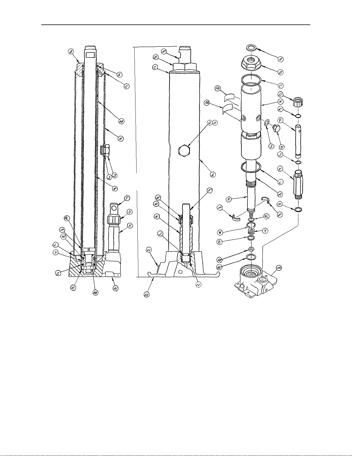
Page 11

390–80 Foot Control Jack Assembly (Control End)
15 7/8
Collapsed Height
Item Part No. Part Name Qty. Item Part No. Part Name Qty.
A45–904 Quad Ring 1 W 926–20–162 Wear Ring 1
B 390–2–121 Machined Cap 1 Y 926–20–160 Piston End 1
C 390–1–243 Gasket 1 Z 926–20–161 Cup Packing 1
D 390–2–137 Pump Cap 1 AB 15–13 Hex Jam Nut 1
E 390–2–128 Packing 1 AC 390–1–238 Actuator Gasket 1
F 390–2–135 Pump Piston 1 AD 946–1–293 Label 1
H 390–2–149 Reservoir 1 AF 48–14 90_ Swivel Coupling 1
J45–110 O–Ring 2 AH 390–2–147 90_ Male Elbow 1
K 390–2–136 Pump Cylinder 1 AK (page 25) Jack Base 1
L 390–1–244 Base Gasket 1 AL 45–14 O–Ring 1
M 390–2–126 Actuator Cylinder 1 AN 36–22 Label 1
N 390–1–237 Pump Gasket 1 AP 962–1–152 Relief Valve (not shown) 1
P 390–2–139 Retaining Collar 2 AQ 390–2–104 Low Pressure Hose (not shown) 1
R 390–2–127 Actuator 1 AR 390–2–101 Pressure Line (not shown) 1
S 388–1–38 Plug 1 AS 390–2–183 Seal Kit (not shown) A/R
10
Page 12

390–79 Foot Control Jack Ass’y (Non–Control End)
15 7/8
Collapsed Height
Item Part No. Part Name Qty. Item Part No. Part Name Qty.
A45–904 Quad Ring 1 W 390–2–127 Actuator 1
B 390–2–121 Machined Cap 1 Y 926–20–160 Piston End 1
C 390–1–243 Gasket 1 Z 926–20–161 Cup Packing 1
D 390–2–137 Pump Cap 1 AB 15–13 Hex Jam Nut 1
E 926–20–162 Wear Ring 1 AC 390–1–238 Actuator Gasket 1
H 390–2–128 Packing 1 AD 946–1–293 Label 1
J 388–1–38 Plug 1 AF 48–14 90_ Swivel Coupling 1
K 390–2–135 Pump Piston 1 AH 390–2–147 90_ Male Elbow 1
L 390–2–149 Reservoir 1 AK (page 25) Jack Base 1
M45–110 O–Ring 2 AL 45–14 O–Ring 1
N 390–1–244 Base Gasket 1 AN 36–23 Label 1
P 390–2–126 Actuator Cylinder 1 AP 962–1–152 Relief Valve (not shown) 1
R 390–2–139 Retaining Collar 2 AR 390–2–103 Low Pressure Line (not shown) 1
S 390–2–136 Pump Cylinder 1 AS 390–2–102 Pressure Line (not shown) 1
T 390–1–237 Pump Gasket 1 AT 390–2–183 Seal Kit (not shown) A/R
11
Page 13

Base Assembly with Low Foot Control Jacks
Assembly part number 921–25 (reference only)
DD
DE
12
Page 14

Base Assembly with Low Foot Control Jacks
Item Part No. Part Name Qty. Item Part No. Part Name Qty.
A38–10 Clamp 2 BC 763–1–15 Jack Spring 2
B25–38 Pop Rivet 4 BD 763–1–14 Spring Guide 2
C 390–3–218 Cover Spacer 2 BE 390–2–95 Jack Hood Top 1
D 390–2–81 Label, ”This End” 1 BF 390–3–97 Center Base Tube Hood 1
E 390–2–80 Label, ”Other End” 1 BH 763–1–16 Sleeve 2
F48–12 90_ Street Elbow 2 BJ 14–7 Washer As Req.
H 390–2–103 Return Line 1 BK 390–3–198 Rear Support Collar 1
J48–13 Needle Valve 2 BL 763–1–13 Jack Spring 2
K 390–2–64 Pin 1 BM 962–1–252 Relief Valve 2
L11–1 Washer 4 BN 390–2–106 Bumper 2
M27–4 Cotter Pin 6 BP 3–37 Hex Hd. Cap Screw 2
N21–25 Set Screw 2 BR 21–95 Set Screw 4
P 390–2–65 Lever Assembly 2 BS 15–12 Hex Nut 4
R38–32 Extension Spring 2 BT 38–31 Cable Tie 2
S 390–1–77 Rear Pivot Link 1 BW 2–15 Machine Screw 2
T (page 26) Left Pedal 1 BY 15–22 Hex Nut 2
W (page 26) Right Pedal 1 BZ 390–3–219 Fifth Wheel Hole Cover 1
Y 390–2–102 Pressure Line 1 CA 15–3 Hex Nut 6
Z 390–2–101 Pressure Line, Cont. End 1 CB 390–2–119 Modified Eye Bolt 2
AB 16–6 Kep Nut 4 CC 12–5 Lock Washer 4
AC 3–32 Hex Hd. Cap Screw 2 CD 921–1–252 Serial No. Tag 1
AD 27–3 Cotter Pin 4 CE 390–2–104 Return Line, Cont. End 1
AE 390–2–70 Adjustment Rod 2 CF (page 14) Head End Jack Ass’y1
AF 48–14 90_ Swivel Coupling 2 CH 390–2–96 J. Hood Top, Cont. End 1
AH 14–9 Washer 2 CJ 921–27–35 Hood Slide 3
AJ 16–11 Hex Nut 2 CK 921–27–31 Lt. Jack Hood Ass’y1
AK 28–97 Retaining Ring 2 CL 921–25–10 Control Rod 2
AL 11–13 Washer 2 CM 921–27–37 Control Cover Ass’y1
AM 763–1–19 Pump Link Rod Assembly 2 CN (page 15) Foot End Jack Ass’y1
AN 23–25 Hex Wash. Hd. Tap. Scr. 29 CP 921–27–29 Inside Jack Hood Ass’y1
AP 11–46 Washer 2 CR 921–27–25 Outside Jack Hood Ass’y1
AR 390–3–194 Hinge Plate 1 CS 921–27–39 Hood Slide 1
AS 11–53 Washer 2 CT 921–27–33 Inside Jack Hood Ass’y1
AT 390–3–185 Pump Connecting Rod 1 CW 921–27–27 Rt. Side Jack Hood Ass’y1
AW (page 26) Pump Pedal Assembly 1 CY 921–27–21 Angle Brace 4
AY 8–12 Shoulder Bolt 2 CZ 390–3–196 Valve Support 1
AZ 4–14 Soc. Hd. Cap Screw 8 DB 921–1–251 Label 1
BA 390–1–67 Jack Washer 2 DD 921–1–250 Label 1
BB 11–63 Washer 8 DE 920–1–224 Label 1
13
Page 15
921–39 Low Foot Control Jack Ass’y (Non–Control End)
Collapsed Height
13 17/64
Item Part No. Part Name Qty. Item Part No. Part Name Qty.
A45–904 Quad Ring 1 S 388–1–38 Plug 1
B 390–2–121 Machined Cap 1 W 926–20–162 Wear Ring 1
C 390–1–243 Gasket 1 Y 926–20–160 Piston End 1
D 390–2–137 Pump Cap 1 Z 926–20–161 Cup Packing 1
E 390–2–128 Packing 1 AB 15–13 Hex Jam Nut 1
F 390–2–135 Pump Piston 1 AC 390–1–238 Actuator Gasket 1
H 921–27–11 Reservoir 1 AD 946–1–293 Label 1
J45–110 O–Ring 2 AK (page 25) Jack Base 1
K 390–2–136 Pump Cylinder 1 AL 45–14 O–Ring 1
L 390–1–244 Base Gasket 1 AN 36–30 Label 1
M 921–27–12 Actuator Cylinder 1 AP 962–1–152 Relief Valve (not shown) 1
N 390–1–237 Pump Gasket 1 AQ 390–2–103 Low Pressure Line (not shown) 1
P 390–2–139 Retaining Collar 2 AR 390–2–102 Pressure Line (not shown) 1
R 921–27–13 Actuator 1 AS 390–2–183 Seal Kit (not shown) A/R
14
Page 16

921–38 Low Foot Control Jack Assembly (Control End)
Collapsed Height
13 17/64
Item Part No. Part Name Qty. Item Part No. Part Name Qty.
A45–904 Quad Ring 1 S 388–1–38 Plug 1
B 390–2–121 Machined Cap 1 W 926–20–162 Wear Ring 1
C 390–1–243 Gasket 1 Y 926–20–160 Piston End 1
D 390–2–137 Pump Cap 1 Z 926–20–161 Cup Packing 1
E 390–2–128 Packing 1 AB 15–13 Hex Jam Nut 1
F 390–2–135 Pump Piston 1 AC 390–1–238 Actuator Gasket 1
H 921–26–17 Reservoir 1 AD 946–1–293 Label 1
J45–110 O–Ring 2 AK (page 25) Machined Jack Base 1
K 390–2–136 Pump Cylinder 1 AL 45–14 O–Ring 1
L 390–1–244 Base Gasket 1 AN 36–31 Label 1
M 921–27–12 Actuator Cylinder 1 AP 962–1–152 Relief Valve (not shown) 1
N 390–1–237 Pump Gasket 1 AR 390–2–104 Low Pressure Line (not shown) 1
P 390–2–139 Retaining Collar 2 AS 390–2–101 Pressure Line (not shown) 1
R 921–27–13 Actuator 1 AT 390–2–183 Seal Kit (not shown) A/R
15
Page 17

16
Assembly part number 390–28
(reference only)
Base Assembly with Hand Control Jacks
BK
BL
Page 18

Base Assembly with Hand Control Jacks
Item Part No. Part Name Qty.
A 390–2–12 Label, Foot End 1
B 946–20–18 Round Plastic Knob 2
C45–115 O–Ring 2
D11–25 Washer 2
E 390–2–10 Label, Head End 1
F 388–2–26 Jack Hood 4
H 388–2–28 Hood Slide 4
J 390–2–13 Lt. Control Rod Ass’y, Long 1
K 390–2–11 Left Control Tube 1
L 390–2–6 Rt. Control Rod Ass’y, Short 1
M 390–2–4 Right Control Tube 1
N21–25 Set Screw 8
P 390–3–199 Control Tube Collar 2
R 390–2–24 Hood Cap 2
S23–25 Sheet Metal Screw 4
T37–2 Hole Plug 2
W 390–2–27 Pin Eye Assembly 2
Y4–14 Soc. Hd. Cap Screw 8
Z27–3 Cotter Pin 2
AA 763–1–16 Sleeve 2
AB 921–1–252 Serial No. Tag 1
AC 11–13 Washer 2
AD 390–1–77 Rear Pivot Link 1
AE 28–97 Lock Ring 2
AF 38–10 Hold All Clamp 2
AH 25–38 Pop Rivet 4
AJ 8–12 Shoulder Bolt 2
AK 16–11 Hex Nut 2
AL 390–3–185 Pump Connecting Rod 1
AM 390–2–22 Left Rod Clip 2
AN (page 18) Jack Assembly 2
AP 763–1–14 Spring Guide 2
AR 763–1–19 Pump Link Rod Assembly 2
AS 390–1–67 Jack Washer 2
AT (page 26) Pump Pedal Assembly 1
AW 390–2–106 Bumper 2
AY 11–63 Washer 8
AZ 390–1–64 Valve Control Adaptor 2
BA 763–1–15 Jack Spring 2
BB 21–40 Set Screw 2
BC 14–9 Washer As Req’d
BD 388–2–20 Control Rod Assembly 2
BF 921–1–251 Label 1
BJ 4–66 Soc. Hd. Cap Screw 2
BK 920–1–224 Decorative Label 1
BL 921–1–250 Specification Label 1
17
Page 19

390–90 Hand Control Jack Assembly
15 7/8
Collapsed Height
Item Part No. Part Name Qty. Item Part No. Part Name Qty.
A45–904 Quad Ring 1 W 390–2–127 Actuator 1
B 390–2–121 Cap, Machined 1 Y 926–20–160 Piston End 1
C 390–1–243 Gasket 1 Z 926–20–161 Cup Packing 1
D 390–2–137 Pump Cap 1 AB 15–13 Hex Jam Nut 1
E45–8O–Ring 1 AC 390–1–238 Actuator Gasket 1
H 390–2–128 Packing 1 AD 946–1–293 Label 1
J 388–1–38 Plug 1 AE 390–1–64 Valve Control Adapter 1
K 390–2–135 Pump Piston 1 AF 21–40 Set Screw 1
L 388–1–39 Reservoir 1 AK (page 25) Jack Base 1
M45–110 O–Ring 2 AL 45–14 O–Ring 1
N 390–1–244 Base Gasket 1 AM 390–1–226 Release Valve 1
P 390–2–126 Actuator Cylinder 1 AN 926–20–162 Wear Ring 1
R 390–2–139 Retaining Collar 2 AP 36–21 Label 1
S 390–2–136 Pump Cylinder 1 AR 390–2–183 Seal Kit (not shown) A/R
T 390–1–237 Pump Gasket 1
18
Page 20

921–40 Low Hand Control Jack Assembly
Item Part No. Part Name Qty. Item Part No. Part Name Qty.
A45–904 Quad Ring 1 W 921–27–13 Actuator 1
B 390–2–121 Cap, Machined 1 Y 926–20–160 Piston End 1
C 390–1–243 Gasket 1 Z 926–20–161 Cup Packing 1
D 390–2–137 Pump Cap 1 AB 15–13 Hex Jam Nut 1
E45–8O–Ring 1 AC 390–1–238 Actuator Gasket 1
H 390–2–128 Packing 1 AD 946–1–293 Label 1
J 388–1–38 Plug 1 AE 390–1–64 Valve Control Adapter 1
K 390–2–135 Pump Piston 1 AF 21–40 Set Screw 1
L 921–26–17 Reservoir 1 AK (page 25) Jack Base 1
M45–110 O–Ring 2 AL 45–14 O–Ring 1
N 390–1–244 Base Gasket 1 AM 390–1–226 Release Valve 1
P 921–27–12 Actuator Cylinder 1 AN 926–20–162 Wear Ring 1
R 390–2–139 Retaining Collar 2 AP 36–32 Label 1
S 390–2–136 Pump Cylinder 1 AQ 390–2–183 Seal Kit A/R
T 390–1–237 Pump Gasket 1
19
Page 21

20
Assembly part number 921–26
(reference only)
Base Assembly with Low Hand Control Jacks
BK
BL
Page 22

Base Assembly with Low Hand Control Jacks
Item Part No. Part Name Qty. Item Part No. Part Name Qty.
A 390–2–12 Label, Foot End 1 AE 28–97 Lock Ring 2
B 946–20–18 Round Plastic Knob 2 AF 38–10 Clamp 2
C45–115 O–Ring 2 AH 25–38 Pop Rivet 4
D11–25 Washer 2 AJ 8–12 Shoulder Bolt 2
E 390–2–10 Label, Head End 1 AK 16–11 Hex Nut 2
F 388–2–26 Jack Hood 4 AL 390–3–185 Pump Connecting Rod 1
H 388–2–28 Hood Slide 4 AM 390–2–22 Left Rod Clip 2
J 390–2–13 Left Control Rod Ass’y 1 AN (page 19) Jack Assembly 2
K 390–2–11 Left Control Tube 1 AP 763–1–14 Spring Guide 2
L 390–2–6 Right Control Rod Ass’y 1 AR 763–1–19 Pump Link Rod Ass’y2
M 390–2–4 Right Control Tube 1 AS 390–1–67 Jack Washer 2
N21–25 Set Screw 8 AT (page 26) Pump Pedal Ass’y1
P 390–3–199 Control Tube Collar 2 AW 390–2–106 Bumper 2
R 921–26–12 Hood Cap 2 AY 11–63 Washer 8
S23–25 Sheet Metal Screw 4 AZ 390–1–64 Valve Control Adaptor 2
T37–2 Hole Plug 2 BA 763–1–15 Jack Spring 2
W 390–2–27 Pin Eye Assembly 2 BB 21–40 Set Screw 2
Y4–14 Soc. Hd. Cap Screw 8 BC 14–9 Washer As Req.
Z27–3 Cotter Pin 2 BD 388–2–20 Control Rod Ass’y2
AA 763–1–16 Sleeve 2 BF 921–1–251 Label 1
AB 921–1–252 Serial No. T ag 1 BJ 4–66 Soc. Hd. Cap Screw 2
AC 11–13 Washer 2 BK 920–1–224 Label 1
AD 390–1–77 Rear Pivot Link 1 BL 921–1–250 Label 1
21
Page 23

22
Assembly part number 921–27 (Low Jacks)
Assembly part number 921–28 (Standard Jacks)
(reference only)
Base Assembly with Push Button Jacks
CZ
CY
Page 24

Base Assembly with Push Button Jacks
Base with Low Jacks
Item Part No. Part Name Qty. Item Part No. Part Name Qty.
A38–10 Clamp 2 AZ 4–14 Soc. Hd. Cap Screw 8
B25–38 Pop Rivet 4 BA 390–1–67 Jack Washer 2
C 390–3–218 Cover Spacer 2 BB 11–63 Washer 10
D 921–27–23 Push Button Control 2 BC 763–1–15 Jack Spring 2
E 921–27–19 Push Button Holder 1 BD 763–1–14 Spring Guide 2
F48–12 90_ Street Elbow 2 BE 390–2–95 Jack Hood Top 1
H 390–2–103 Return Line 1 BF 390–3–97 Center Base Tube Hood 1
J48–13 Needle Valve 2 BH 763–1–16 Sleeve 2
K 390–2–64 Pin 1 BJ 14–7 Washer As Req.
L 921–27–20 Cable Support 1 BK 390–3–198 Rear Support Collar 1
M27–4 Cotter Pin 2 BL 25–73 Pop Rivet 2
N21–25 Set Screw 2 BM 962–1–152 Relief Valve 2
P 390–2–65 Lever Assembly 2 BN 390–2–106 Bumper 2
R 390–3–196 Valve Support 1 BP 3–37 Hex Hd. Cap Screw 2
S 390–1–77 Rear Pivot Link 1 BR 21–95 Set Screw 4
T16–3 Fiberlock Nut 2 BS 15–12 Hex Nut 4
W 921–27–22 Cable Connector 2 BT 38–31 Cable Tie 2
Y 390–2–102 Pressure Line 1 BW 2–15 Machine Screw 4
Z 390–2–101 Pressure Line, Cont. End 1 BY 15–22 Hex Nut 2
AA 460–2–19 Switch Cord Grommet 2 BZ 390–3–219 Fifth Wheel Hole Cover 1
AB 16–6 Kep Nut 2 CA 15–3 Hex Nut 4
AC 28–6 Lock Ring 2 CB 921–27–25 Outside Jack Hood Ass’y1
AD 27–3 Cotter Pin 2 CC 12–5 Lock Washer 4
AE 921–27–21 Angle Brace 4 CD 921–1–252 Serial No. Tag 1
AF 48–14 90_ Swivel Coupling 2 CE 390–2–104 Return Line, Cont. End 1
AH 14–9 Washer 2 CF (page 14) Jack Ass’y, Head 1
AJ 16–11 Hex Nut 2 CH 921–27–36 Jack Hood Top, Cont. End 1
AK 28–97 Retaining Ring 2 CJ 921–27–35 Hood Slide 3
AL 11–13 Washer 2 CK 921–27–31 Jack Hood Ass’y, Lt. 1
AM 763–1–19 Pump Link Rod Ass’y 2 CL 921–27–29 Inside Jack Hood Ass’y1
AN 23–25 Hex Wash. Hd. Tap. Scr. 29 CM 921–27–37 Control Cover Ass’y1
AP 921–27–27 Jack Hood Ass’y, Rt . 1 CN (page 15) Jack Ass’y, Foot 1
AR 921–27–33 Inside Jack Hood Ass’y 1 CP 921–27–40 Label 1
AS 921–27–39 Hood Slide 1 CR 21–63 Set Screw 2
AT 390–3–185 Pump Connecting Rod 1 CT 921–1–251 Label 1
AW (page 26) Pump Pedal Assembly 1 CY 920–1–224 Label 1
AY 8–12 Shoulder Bolt 2 CZ 921–1–250 Label 1
23
Page 25

Base Assembly with Push Button Jacks
Base with Standard Jacks
Item Part No. Part Name Qty. Item Part No. Part Name Qty.
A38–10 Clamp 2 AZ 4–14 Soc. Hd. Cap Screw 8
B25–38 Pop Rivet 4 BA 390–1–67 Jack Washer 2
C 390–3–218 Cover Spacer 2 BB 11–63 Washer 10
D 921–27–23 Push Button Control 2 BC 763–1–15 Jack Spring 2
E 921–27–19 Push Button Holder 1 BD 763–1–14 Spring Guide 2
F48–12 90_ Street Elbow 2 BE 390–2–95 Jack Hood Top 1
H 390–2–103 Return Line 1 BF 390–3–97 Center Base Tube Hood 1
J48–13 Needle Valve 2 BH 763–1–16 Sleeve 2
K 390–2–64 Pin 1 BJ 14–7 Washer As Req.
L 921–27–20 Cable Support 1 BK 390–3–198 Rear Support Collar 1
M27–4 Cotter Pin 2 BL 25–73 Pop Rivet 2
N21–25 Set Screw 2 BM 962–1–152 Relief Valve 2
P 390–2–65 Lever Assembly 2 BN 390–2–106 Bumper 2
R 390–3–196 Valve Support 1 BP 3–37 Hex Hd. Cap Screw 2
S 390–1–77 Rear Pivot Link 1 BR 21–95 Set Screw 4
T16–3 Fiberlock Nut 2 BS 15–12 Hex Nut 4
W 921–27–22 Cable Connector 2 BT 38–31 Cable Tie 2
Y 390–2–102 Pressure Line 1 BW 2–15 Machine Screw 4
Z 390–2–101 Pressure Line, Cont. End 1 BY 15–22 Hex Nut 2
AA 460–2–19 Switch Cord Grommet 2 BZ 390–3–219 Fifth Wheel Hole Cover 1
AB 16–6 Kep Nut 2 CA 15–3 Hex Nut 4
AC 28–6 Lock Ring 2 CB 390–3–85 Outside Jack Hood Ass’y1
AD 27–3 Cotter Pin 2 CC 12–5 Lock Washer 4
AE 390–2–113 Straight Support Bar 4 CD 921–1–252 Serial No. Tag 1
AF 48–14 90_ Swivel Coupling 2 CE 390–2–104 Return Line, Cont. End 1
AH 14–9 Washer 2 CF (page 11) Jack Ass’y, Head 1
AJ 16–11 Hex Nut 2 CH 921–27–36 Jack Hood Top, Cont. End 1
AK 28–97 Retaining Ring 2 CJ 390–2–28 Hood Slide 3
AL 11–13 Washer 2 CK 390–3–88 Jack Hood Ass’y, Lt. 1
AM 763–1–19 Pump Link Rod Ass’y 2 CL 390–2–93 Inside Jack Hood Ass’y1
AN 23–25 Hex Wash. Hd. Tap. Scr. 29 CM 390–3–80 Control Cover Ass’y1
AP 390–3–82 Jack Hood Ass’y, R t . 1 CN (page 10) Jack Ass’y, Foot 1
AR 390–2–90 Inside Jack Hood Ass’y 1 CP 921–27–40 Label 1
AS 390–2–142 Hood Slide 1 CR 21–63 Set Screw 2
AT 390–3–185 Pump Connecting Rod 1 CT 921–1–251 Label 1
AW (page 26) Pump Pedal Assembly 1 CY 920–1–224 Label 1
AY 8–12 Shoulder Bolt 2 CZ 921–1–250 Label 1
24
Page 26

Jack Base Assembly
Assembly part number 926–1–290 (Hand Control Jack)
Assembly part number 926–1–295 (Foot Control Jack)
(reference only)
Item Part No. Part Name Qty.
A 946–1–289 Jack Base, Hand Control 1
946–1–291 Jack Base, Foot Control 1
B 926–20–154 Seal 1
C 926–20–153 Check Valve 1
D 926–20–156 Seal 1
E 926–20–159 Valve Plug 1
F 926–20–157 Base Plug 1
H 926–20–155 Seal 1
J 926–20–152 Check Valve 1
K 926–20–158 Reservoir Plug 1
25
Page 27

390–2–190 Pump Pedal Assembly
Item Part No. Part Name Qty.
A 390–2–193 Pump Link & Bar Ass’y1
B 390–1–53 Rubber Pedal 1
C 650–1–48 Rubber Bumper 1
390–3–182 & 390–3–183 Release Pedal Ass’y, Rt. & Lt.
Item Part No. Part Name Qty. Item Part No. Part Name Qty.
A 390–2–54 Right Pedal Assembly 1 A 390–2–55 Left Pedal Assembly 1
B37–11 Neoprene Cap 1 B 37–11 Neoprene Cap 1
C 650–1–48 Rubber Bumper 1 C 650–1–48 Rubber Bumper 1
D 390–1–53 Rubber Pedal 1 D 390–1–53 Rubber Pedal 1
E16–6 Hex Kep Nut 1 E 16–6 Hex Kep Nut 1
F3–3 Hex Hd. Cap Screw 1 F 3–3 Hex Hd. Cap Screw 1
26
Page 28

20”, 24”, 29” Litter Carrier Assembly
HEAD END
AB
*Previous to May, 1984, ”U” Section Assembly had a crimped
bottom I.V. pole holder and 393–3–68 insert was used
Item Part No. Part Name Qty. Item Part No. Part Name Qty.
B2–4 Rd. Hd. Mach. Screw 2 P 399–16–14 Support Tube Liner 4
C16–16 FIberlock Nut 12 R 390–9–9 Ft. End Support Tube 2
D 390–3–34 Nylon Bumper 4 S 390–4 Spring Clip 2
E16–7 Fiberlock Nut 2 T 42–7 Collar Assembly 4
F 390–9–15 U–Section Ass’y (20”) 2 W 390–9–7 Support Tube Assembly 2
F 399–9–7U–Section Ass’y (24”) 2 Y 390–9–13 Top Supt. Tube Ass’y (20”)2
F 393–9–7U–Section Ass’y (29”) 2 Y 399–9–13 Top Supt. Tube Ass’y (24”)2
H 393–3–29 Litter Bracket Brace 2 Y 393–9–13 Top Supt. Tube Ass’y (29”)2
J26–14 Roll Pin 2 Z 46–1 Set Screw 2
K3–4 Hex Hd. Cap Screw 12 AA 921–36–21* I.V. Pole Insert 4
M21–75 Set Screw 2 AB 26–111 Roll Pin 4
N 399–9–2 Side Rail Assembly 2
27
Page 29

24” Litter Carrier Assembly (With Optional Push Bar)
Assembly part number 921–30–10 (reference only)
HEAD END
Item Part No. Part Name Qty. Item Part No. Part Name Qty.
B2–4 Rd. Hd. Mach. Screw 1 R 390–9–9 Foot End Support Tube 2
C16–16 Fiberlock Nut 12 S 390–4 Spring Clip 1
D 390–3–34 Nylon Bumper 4 T 42–7 Collar Assembly 4
E16–7 Fiberlock Nut 1 W 390–9–7 Support Tube Assembly 2
F 399–9–7U–Section Assembly 1 Y 399–9–13 Top Support Tube Ass’y2
H 393–3–29 Litter Bracket Brace 2 Z 46–1 Set Screw 2
J26–14 Roll Pin 2 AA (page 29) Pushbar Assembly 1
K3–4 Hex Hd. Cap Screw 10 AB 26–35 Roll Pin 2
L 921–30–12 Crossbar Assembly 1 AC 3–5 Hex Hd. Cap Screw 2
M21–75 Set Screw 2 AD 921–36–21 I.V. Pole Insert 4
N 399–9–2 Side Rail Assembly 2 AE 26–111 Roll Pin 4
P 399–16–14 Support Tube Liner 4
28
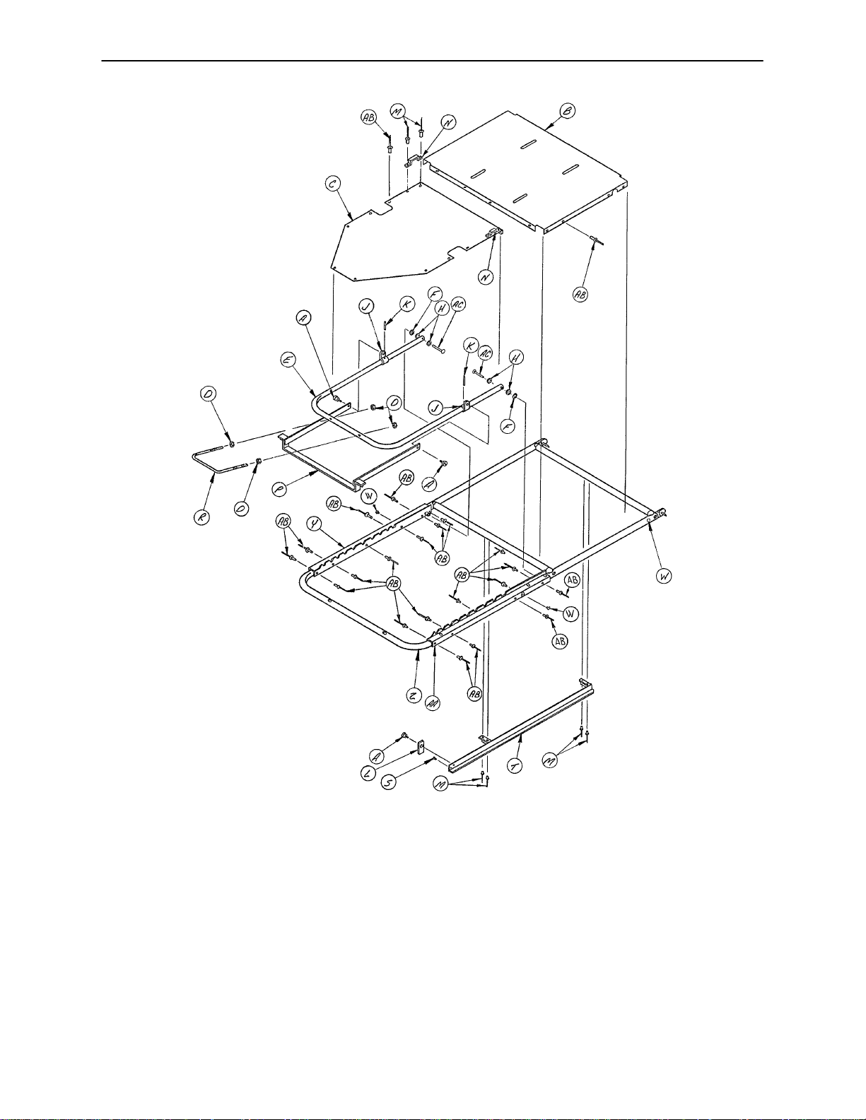
Page 30

Optional Folddown Pushbar Assembly
Assembly part number
921–30–14
(reference only)
Item Part No. Part Name Qty.
A 921–30–33 Tube Assembly, Rt. 1
B 921–30–34 Tube Assembly, Lt. 1
C3–51 Hex Hd. Cap Screw 4
D17–4 Acorn Nut 4
E 921–30–20 Upright Assembly 1
F38–108 Compression Spring 2
H 921–30–26 Plunger 2
J 921–30–25 Insert 1
K 921–30–30 Spring Clip 1
L2–4 Rd. Hd. Mach. Screw 1
M16–7 Fiberlock Nut 1
N 921–30–27 Grip 1
P 921–30–31 Label 1
R 921–30–28 Pin 2
S21–50 Set Screw 2
T 921–30–32 Label 1
29
Page 31

20”, 24”, 29” Aluminum Manual Fowler Assembly
30
Page 32

20”, 24”, 29” Aluminum Manual Fowler Assembly
Item Part No. Part Name Qty.
A 390–525–16 Litter Frame Tube (20”)2
A 390–24–7 Litter Frame Tube (24”)2
A 393–29–7 Litter Frame Tube (29”)2
B 378–24–53 Connector Pin (20”)2
B 381–24–6 Connector Pin (24”)2
B 381–29–3 Connector Pin (29”)2
C26–12 Roll Pin 4
D 381–20–3 Position Bracket Ass’y, Lt. 1
E 378–24–15 Pivot Plate Assembly 2
F 381–20–4 Position Bracket Ass’y, Rt. 1
H25–17 Semi–Tubular Rivet 2
J14–4 Nylon Washer 4
K28–28 Retaining Ring 2
L 381–20–6 Fowler Lock Ass’y (20”)1
L 381–24–2 Fowler Lock Ass’y (24”)1
L 381–29–1 Fowler Lock Ass’y (29”)1
P 460–4–39 Posterior Handle 1
R15–12 Hex Nut 4
S 386–20–2 Fowler Frame (20”)1
S 390–24–1 Fowler Frame (24”)1
S 393–29–1 Fowler Frame (29”)1
T 940–2–134 Hinge Bracket 2
W26–57 Roll Pin 2
Z25–55 Pop Rivet 50
AA 386–20–3 Head End Top (20”)1
AA 390–24–4 Head End Top (24”)1
AA 393–29–4 Head End Top (29”)1
AB 381–20–8 Foot End Top (20”)1
AB 390–24–5 Foot End Top (24”)1
AB 378–29–4 Foot End Top (29”)1
AC 378–24–42 Formed Washer 4
AD 8–13 Shoulder Bolt 2
AE 25–40 Pop Rivet 4
AF 381–24–7 Velcro Pile 1
AH 381–29–5 Label 1
AK 1–34 Flat Hd. Mach. Screw 2
AL 381–20–9 Crossbar (20”)1
AL 960–1–7 Crossbar (24”)1
AL 940–1–11 Crossbar (29”)1
AM 940–2–10 Crossbar Mount 2
31
Page 33

20”, 24”, 29” Aluminum Crank Fowler Litter Assembly,
Head End Crank
AZ
BG
32
Page 34

20”, 24”, 29” Aluminum Crank Fowler Litter Assembly,
Head End Crank
Item Part No. Part Name Qty.
A 389–22–2 Litter Frame Ass’y (20”)1
A 378–24–44 Litter Frame Ass’y (24”)1
A 378–29–2 Litter Frame Ass’y (29”)1
B 378–24–8 Left Hand Nut 1
C 378–24–15 Pivot Plate Assembly 2
D 389–22–1 Head End Frame (20”)1
D 389–32–33 Head End Frame (24”)1
D 389–34–14 Head End Frame (29”)1
E 386–20–3 Head End Top (20”)1
E 390–24–4 Head End Top (24”)1
E 393–29–4 Head End Top (29”)1
H1–34 Flat Hd. Mach. Screw 2
J 378–24–9 Collar 1
K 378–24–23 Roller 2
M 378–24–22 Riser Bar 2
N 940–2–134 Hinge Bracket, Machined 2
P8–13 Shoulder Bolt 2
S 378–24–42 Formed Washer 2
T37–19 Button 2
W 378–24–37 Threaded Shaft 1
Y 378–24–46 Collar 2
Z81–148 Thrust Bearing 1
AA 81–149 Thrust Washer 2
AB 378–24–33 Handle Assembly 1
AC 378–24–30 Knob 1
AD 378–24–29 Shoulder Bolt 1
AE 26–56 Roll Pin 1
AJ 26–43 Roll Pin 3
AK 16–6 Kep Nut 1
AM 11–53 Washer 2
AN 381–20–8 Foot End Skin (20”)1
AN 390–24–5 Foot End Skin (24”)1
AN 378–29–4 Foot End Skin (29”)1
AP 7–4 Machine Screw 2
AR 28–28 Retaining Ring 2
AS 14–4 Nylon Washer 4
AT 25–55 Rivet 37
AW 26–57 Roll Pin 2
AY 25–17 Rivet 2
AZ 381–24–7 Velcro Pile 1
BA 25–40 Pop Rivet 4
BB 378–24–36 Adaptor (24” & 29”)1
BC 381–24–5 Label 1
BD 389–22–4 Crossbar Ass’y, Hd. (20”)1
BD 373–24–5 Crossbar Ass’y, Hd. (24”)1
BD 935–34–25 Crossbar Ass’y, Hd. (29”)1
BE 381–20–10 Crossbar (20”)1
BE 960–1–7 Crossbar (24”)1
BE 940–1–11 Crossbar (29”)1
BF 940–2–10 Crossbar Mounts 2
BG 378–24–38 Screw Support 1
33
Page 35

24”, 29” Crank Fowler Litter Assembly, Foot End Crank
BO
34
Page 36

24”, 29” Crank Fowler Litter Assembly, Foot End Crank
Item Part No. Part Name Qty.
A 373–24–2 Litter Frame Ass’y (24”)1
A 373–29–1 Litter Frame Ass’y (29”)1
B 389–32–30 Right Hand Nut 1
C 378–24–15 Pivot Plate Assembly 2
D 389–32–33 Head End Frame (24”)1
D 389–34–14 Head End Frame (29”)1
E 390–24–4 Head End Top (24”)1
E 393–29–4 Head End Top (29”)1
K 378–24–23 Roller 2
M 378–24–22 Riser Bar 2
N 940–2–134 Hinge Bracket (24”)2
N 940–2–134 Hinge Bracket (29”)2
P8–13 Shoulder Bolt 2
S 378–24–42 Formed Washer 2
W 935–34–5 Threaded Shaft 1
Y 378–24–9 Collar 1
Z81–148 Thrust Bearing 1
AA 81–149 Thrust Washer 2
AB 378–24–33 Handle Assembly 1
AC 378–24–30 Knob 1
AD 378–24–29 Shoulder Bolt 1
AE 26–56 Roll Pin 1
AJ 26–43 Roll Pin 4
AK 16–6 Kep Nut 1
AM 11–53 Washer 2
AN 390–24–5 Foot End Skin (24”)1
AN 378–29–4 Foot End Skin (29”)1
AP 7–4 Truss Hd. Mach. Screw 2
AR 28–28 Retaining Ring 2
AS 14–4 Nylon Washer 4
AT 25–55 Rivet 41
AW 26–57 Roll Pin 2
AY 25–17 Rivet 2
AZ 381–24–7 Velcro Pile 1
BA 25–40 Pop Rivet 4
BB 389–34–18 Adaptor 1
BC 28–6 Retaining Ring 1
BD 389–32–17 Connecting Rod 1
BE 935–29–10 Rod Brace 1
BF 389–32–16 Screw Coupler 1
BH 378–24–46 Collar 1
BK 1–34 Flat Hd. Mach. Screw 4
BL 373–24–5 Crossbar Ass’y, Hd. (24”)1
BL 935–34–25 Crossbar Ass’y, Hd. (29”)1
BM 960–1–7 Crossbar (24”)2
BM 940–1–11 Crossbar (29”)2
BN 940–2–10 Crossbar Mounts 4
BO 378–24–38 Screw Support 1
35
Page 37

24”, 29” Crank Fowler/Crank Knee Gatch Litter Assembly
CN
36
Page 38

24”, 29” Crank Fowler/Crank Knee Gatch Litter Assembly
Item 24” 29” Part Name Qty.
A 389–32–1 389–34–1 Litter Frame Ass’y1
C 389–34–20 389–34–20 Pos. Brkt. Ass’y, Lt. 1
D 389–32–8 389–34–8 Stationary Skin 1
E 378–24–15 378–24–15 Pivot Plate Ass’y4
F 389–32–33 389–34–14 Head End Frame 1
H 390–24–4 393–29–4 Head End Top 1
N 378–24–23 378–24–23 Roller 4
P 378–24–22 378–24–22 Riser Bar 2
R 940–2–134 940–2–134 Hinge Brkt., Mach. 6
S 389–32–11 389–34–15 Midsection Frame 1
T 389–32–14 389–34–12 Midsection Skin 1
W 389–32–24 389–32–24 Center Riser Bar 2
Y 389–32–13 389–34–6 Hinge 1
Z 389–32–12 389–34–16 Knee Gatch Frame 1
AA 389–32–15 389–34–11 Knee Gatch Skin 1
AB 389–32–27 389–34–17 Lock Assembly 1
AE 389–34–18 389–34–18 Adaptor 1
AF 389–32–17 389–32–17 Connecting Rod 1
AH 389–32–16 389–32–16 Screw Coupler 1
AJ 935–34–5 935–34–5 Threaded Shaft 1
AK 378–24–9 378–24–9 Collar 2
AL 81–148 81–148 Thrust Bearing 2
AM 81–149 81–149 Thrust Washer 4
AN 26–43 26–43 Roll Pin 9
AP 389–34–19 389–34–19 Long Adaptor 1
AR 28–6 ––––– Retaining Ring 1
AS 935–34–6 935–34–6 Gatch Threaded Shaft 1
AT 378–24–33 378–24–33 Handle Assembly 2
AW 378–24–30 378–24–30 Knob 2
AZ 378–24–29 378–24–29 Shoulder Bolt 2
BA 26–56 26–56 Roll Pin 2
BB 378–24–42 378–24–42 Formed Washer 2
BC 11–73 11–73 Washer 1
BD 393–53–20 393–53–20 Strap Anchor 4
BF 16–616–6 Kep Nut 2
BH 26–57 26–57 Roll Pin 6
BJ 25–55 25–55 Rivet 69
BK 25–56 25–56 Rivet 4
BL 25–17 25–17 Rivet 4
BM 14–414–4 Washer 8
BN 11–53 11–53 Washer 4
BP 28–28 28–28 Retaining Ring 4
BR 389–32–30 389–32–30 Right Hand Nut 1
BS 8–13 8–13 Hex Hd. Shoulder Bolt 6
BT 1–34 1–34 Flat Hd. Mach. Screw 4
BW 7–47–4 Truss Hd. Mach. Screw 4
BZ 378–24–8 378–24–8 Left Hand Nut 1
CB 389–34–21 389–34–21 Position Brkt. Ass’y, Rt. 1
CC 378–24–46 378–24–46 Collar 4
CD 381–24–5 381–24–5 Label 1
CE 373–24–5 935–34–25 Crossbar Ass’y, Head 1
CF 389–32–35 935–34–26 Crossbar Ass’y, Foot 1
CH 25–79 25–79 Pop Rivet 8
CJ 381–24–7 381–24–7 Velcro Pile 1
CK 25–40 25–40 Pop Rivet 4
CL 960–2–7 940–2–9 Crossbar 2
CM 940–2–10 ––––– Crossbar Mount 4
CN 378–24–38 378–24–38 Screw Support 1
37
Page 39

24” Fiberresin Pneumatic Fowler Assembly
Assembly part number 921–22–10
(reference only)
38
Page 40

24” Fiberresin Pneumatic Fowler Assembly
Item Part No. Part Name Qty.
A 921–22–11 Litter Frame Tube, Short 2
B 921–22–12 Litter Frame Tube, Long 2
C 381–24–6 Connector Pin 2
D26–12 Roll Pin 4
E 921–22–32 Litter Crossbrace Ass’y1
F3–17 Hex Hd. Cap Screw 8
J16–6 Kep Nut 8
K 921–22–22 Fowler Pivot Assembly 2
L 378–24–42 Formed Washer 4
M25–55 Pop Rivet 4
N 921–22–13 Pivot Block Assembly 1
P 921–22–31 Threaded Pivot 2
R 921–22–26 Release Cable 1
S 921–22–63 Cable Stop 1
T15–23 Hex Nut 2
W (page 40) Fowler Frame Assembly 1
Y 381–24–7 Velcro Pile 1
Z25–69 Pop Rivet 19
AB 1010–31–77 Gas Cylinder 1
AC 921–22–20 Shoulder Bolt 1
AD 921–22–21 Spacer 2
AE 15–27 Hex Nut 1
AH 921–20–70 Litter Skin 1
AJ 381–29–5 Label 1
AK 38–111 Cable Tie 2
AL 11–65 Washer 1
AM 38–112 Cable Mount 2
AN 921–22–59 Spacer 2
AP 921–22–60 Connector Pin 2
39
Page 41

24” Pneumatic Fowler Assembly
Assembly part number
921–22–48 (reference only)
Item Part No. Part Name Qty. Item Part No. Part Name Qty.
A 921–22–14 Fowler Frame 1 M 2–66 Rd. Hd. Mach. Screw 1
B 921–22–25 Fowler Plug 2 N 38–109 Compression Spring 2
C 921–22–15 Fowler Crossbrace Ass’y 1 P 921–22–44 Spacer 4
D26–14 Roll Pin 2 R 21–63 Set Screw 4
E 921–22–43 Cable Bracket 1 S 25–50 Pop Rivet 4
F 921–22–38 Handle, Long 1 T 15–12 Hex Nut 4
H 921–22–53 Handle Assembly 1 W 921–22–57 Label 1
J 921–22–64 Nylon Pulley 1 Y 921–22–62 Handle Protector 1
K 921–22–49 Cable Guide 1 Z 921–20–80 Fowler Skin 1
L15–20 Hex Nut 1 AA 25–69 Pop Rivet 10
40
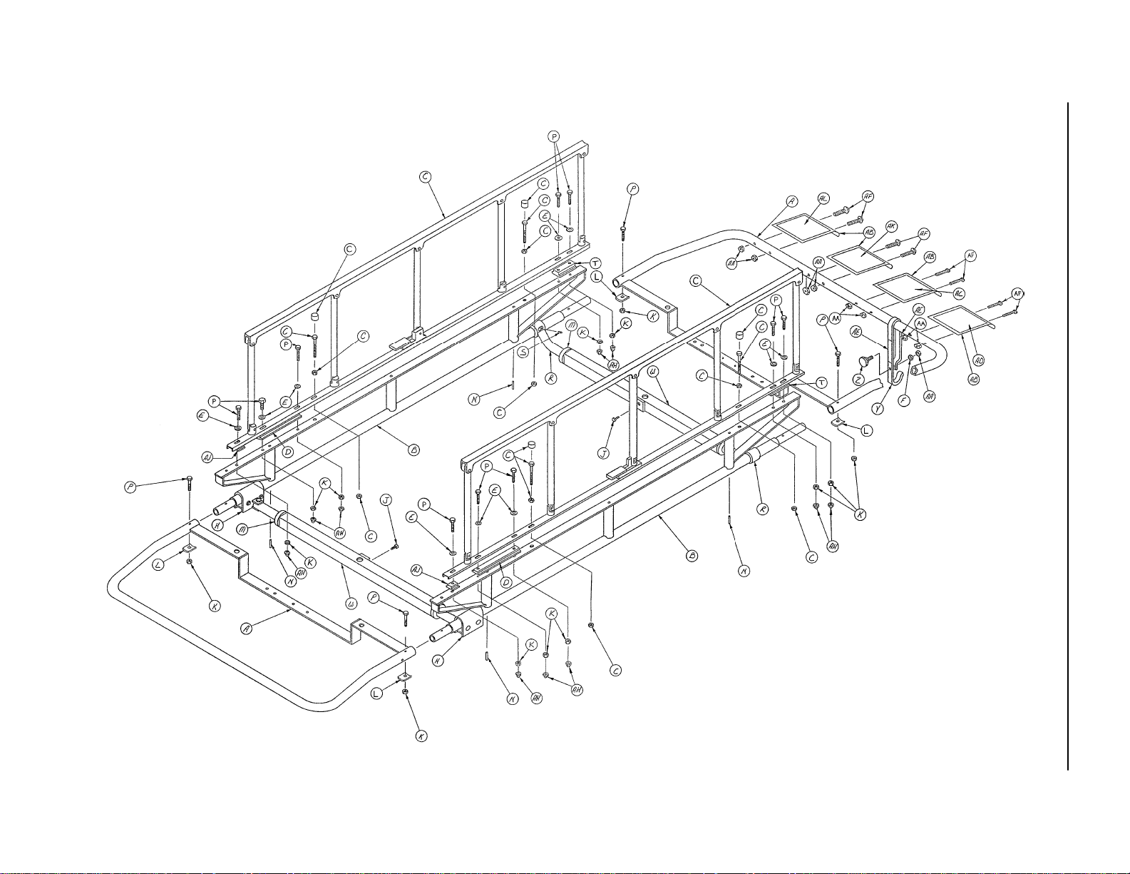
Page 42

24” Fiberresin Manual Fowler Assembly
AK
AK
AA
AK
AH
W
T
S
R
P
Z
K
H
EZ
J
T
Assembly part number 921–20–12 (reference only)
AF
AB
AK
J
W
K
A
C
B
D
Z
Z
L
B
AD
C
Z
Z
Z
EZ
AD
F
AM
Z
AM
Z
A
Item Part No. Part Name Qty. Item Part No. Part Name Qty.
A 390–24–7 Litter Frame Tube 4 S 921–20–54 Fowler Frame 1
B 381–24–6 Connector Pin 2 T 940–2–134 Hinge Bracket, Mach. 2
C26–12 Roll Pin 4 W 26–57 Roll Pin 2
D 381–20–3 Position Brkt. Ass’y, Lt. 1 Z 25–55 Pop Rivet 28
E 378–24–15 Pivot Plate Assembly 2 AA 921–20–75 Head End Top 1
F 381–20–4 Position Brkt. Ass’y, Rt. 1 AB 921–20–70 Foot End Top 1
H25–17 Semi–Tubular Rivet 2 AD 8–13 Shoulder Bolt 2
J14–4 Nylon Washer 4 AF 381–24–7 Velcro Pile 1
K28–28 Retaining Ring 2 AH 381–24–5 Label 1
L 381–24–2 Fowler Lock Ass’y 1 AK 25–69 Pop Rivet 29
P 460–4–39 Posterior Handle 1 AM 378–24–42 Formed Washer 4
R15–12 Hex Nut 4
41
Page 43

Full–Length X–Ray Cassette Assembly
Assembly part number 921–20–16 (reference only)
Item Part No. Part Name Qty. Item Part No. Part Name Qty.
A (page 43) Tray Assembly 1 M 2–36 Rd. Hd. Mach. Screw 8
B 921–20–19 Mounting Block Assembly 1 N 16–3 Fiberlock Hex Nut 8
C14–3 Washer 8 P 921–20–32 Lever Assembly, Left 1
D8–6 Soc. Hd. Shoulder Bolt 4 R 921–20–26 Lever Assembly, Right 1
E1–25 Flat Hd. Mach. Screw 4 S 921–20–25 Handle 2
F 921–20–21 ”U” Channel 2 T 921–20–24 Cap 2
H 7000–1–42 Adhesive Stair Tread As Req’dW21–63 Set Screw 4
J 921–21–37 Bearing 4 Y 921–20–30 Collar 4
K 921–21–38 Bearing 8 Z 921–20–44 Label 1
L25–70 Pop Rivet 8 AA 921–20–52 Label 1
42
Page 44

Full–Length X–Ray Tray Assembly
Assembly part number 921–20–17
(reference only)
Item Part No. Part Name Qty.
A 921–20–18 Tray 1
B 921–20–43 Label Sheet 1
C 7000–1–116 Yellow Tape As Req’d
D 7000–1–117 Red–Orange Tape As Req’d
E 7000–1–118 White Tape As Req’d
43
Page 45

960 SurgiBed Assembly
Assembly part number 960–2
(reference only)
44
Page 46

960 SurgiBed Assembly
Item Part No. Part Name Qty.
A 960–1–46 2” Mattress Set 1
A 960–26 4” Mattress Set 1
B 960–2–132 Nameplate 2
C (page 46) Litter, Head End 1
D3–32 Hex Hd. Cap Screw 4
E11–2 Washer As Req’d
F2–17 Rd. Hd. Mach. Screw 12
H15–4 Hex Nut 17
J (page 47) Litter, Foot End 1
K (page 48) Rail Assembly 1
L 763–1–34 Rubber Stop 1
M21–19 Set Screw 2
N 940–2–161 I.V. Holder, Right 1
P 940–2–158 I.V. Holder, Left 1
R 393–3–68 Insert 2
S 940–1–48 Roller Assembly 1
T 960–1–15 Hold Down Crossbar 1
W 940–1–35 Hold Down Mtg. Bracket 2
Y7–4 Binding Hd. Mach. Screw 1
Z16–20 Centerlock Nut 2
AA 3–2 Hex Hd. Cap Screw 2
AB 2–19 Rd. Hd. Mach. Screw 4
AC 940–1–43 Rear Roller Assembly 1
AD 960–2–14 Splash Shield 1
AE 11–1 Washer As Req’d
AF (page 49) Litter Carrier Assembly 1
AH 16–6 Kep Nut 6
AJ 46–1 Sq. Hd. Set Screw 2
AK 25–38 Pop Rivet 4
AL 940–2–72 Short Lock Screw Ass’y2
AM 940–1–38 Wedge Lock, Modified 2
AN 15–12 Hex Nut 2
AP 460–1–30 Grounding Strip 1
AR 960–2–166 Tray Assembly 1
AS 940–1–98 Mat 1
AT 17–4 Acorn Nut 4
45
Page 47
960 Litter Head End Assembly
Assembly part number
960–2–1
(reference only)
Item Part No. Part Name Qty. Item Part No. Part Name Qty.
A8–9 Shoulder Bolt 3 N 393–53–20 Strap Anchor 2
B 960–2–2 Center Section Skin 1 P 381–24–2 Fowler Lock Ass’y1
C 390–24–4 Head End Skin 1 R 460–4–39 Posterior Handle 1
D15–12 Hex Nut 4 S 4–18 Soc. Hd. Cap Screw 1
E 390–24–1 Fowler Frame 1 T 940–1–22 Litter Hold Down Ass’y1
F28–28 Retaining Ring 2 W 37–19 Button 4
H14–4 Nylon Washer 4 Y 960–2–44 Position Bracket, Lt. 1
J 940–2–134 Hinge Bracket 2 Z 960–2–4 Frame Ass’y, Head End 1
K26–57 Roll Pin 2 AA 960–2–41 Position Bracket, Rt. 1
L 940–2–21 Retainer 1 AB 25–55 Pop Rivet 44
M25–56 Pop Rivet 8 AC 25–17 Rivet 2
46
Page 48

960 Litter Foot End Assembly
Assembly part number
960–2–9 (reference only)
Item Part No. Part Name Qty. Item Part No. Part Name Qty.
A25–55 Pop Rivet 21 N 11–64 Washer 1
B 960–1–12 Foot End Skin 1 P 940–2–136 Spacer 1
C25–18 Rivet 2 R 38–54 Compression Spring 1
D 940–1–30 Extension Bracket 2 S 26–66 Roll Pin 1
E 940–2–137 Latch 1 T 11–65 Washer 1
F8–5 Shoulder Bolt 3 W 960–1–13 Support Tube, Ft. End 1
H 940–1–32 Extension Latch 2 Y 940–2–10 Crossbar Mount 2
J28–28 Retaining Ring 2 Z 26–14 Roll Pin 2
K7–9 Truss Hd. Mach. Screw 1 AA 1–34 Flat Hd. Mach. Screw 2
L 960–2–10 Frame Ass’y , Foot End 1 AB 7–6 Truss Hd. Mach. Screw 2
M25–56 Pop Rivet 4 AC 11–66 Flat Washer 2
47
Page 49

Assembly part number 960–2–23
(reference only)
960 Rail Assembly
Item Part No. Part Name Qty. Item Part No. Part Name Qty.
A 940–1–75 Roller 2 W 15–4 Hex Nut 8
B25–20 Rivet 2 Y 940–1–84 Roller Slide Lock 2
C1–24 Flat Hd. Mach. Screw 4 Z 940–2–85 Roller Slide Assembly 2
E2–44 Rd. Hd. Mach. Screw 4 AA 960–2–24 Rail Assembly, Right 1
F25–17 Rivet 8 AB 940–1–88 Small ”L” Bracket 2
H15–5 Hex Nut 4 AC 940–1–89 Large ”L” Bracket 2
J 391–53–5 Roller 10 AD 124–1–82 Spring 1
K28–28 Retaining Ring 2 AE 25–27 Rivet 6
L 960–1–53 Litter Positioning Bracket 1 AF 940–2–91 Handle 2
M16–3 Fiberlock Nut 4 AH 124–1–78 Bearing 12
N 960–1–54 Mounting Bracket 1 AJ 11–2 Washer 8
P2–17 Rd. Hd. Mach. Screw 7 AK 940–1–96 Roller Bracket 2
R14–4 Washer 1 AL 21–50 Set Screw 1
S17–3 Drive Nut 14 AM 960–1–59 Guide Pin 1
T 960–2–26 Rail Assembly, Left 1 AN 2–18 Rd. Hd. Mach. Screw 4
48
Page 50

960 Litter Carrier Assembly
Assembly part number 960–2–18 (reference only)
AA
Item Part No. Part Name Qty. Item Part No. Part Name Qty.
A (page 97) 5 Spindle Siderail Ass’y, Rt. 1 M 399–31–20 Long Spacer 2
B 960–2–49 Carrier Ft. End Ass’y1 N3–32 Hex Hd. Cap Screw 8
C21–75 Set Screw 2 P 393–3–68 Insert 2
D42–7 Collar Assembly 4 R 11–2 Washer 8
E 940–2–155 Supt. Tube Swivel Ass’y2 S 4–30 Soc. Hd. Cap Screw 2
F 391–34–25 Gamma Angle Tube Ass’y 2 T 940–2–148 I.V. Holder Ass’y2
H 399–9–13 Top Support Tube Ass’y 2 W 960–2–21 Spacer 2
J 399–31–19 Head End Spacer 2 Y 16–6 Kep Nut 10
K 960–2–133 Carrier Hd. End Ass’y1 Z17–4 Acorn Nut 10
L37–2 Hole Plug 2 AA (page 97) 5 Spindle Siderail Ass’y, Lt. 1
49
Page 51

962 Tapered Head End Assembly
Assembly part number
962–1 (reference only)
Item Part No. Part Name Qty. Item Part No. Part Name Qty.
A 962–1–42 2” Mattress 1 S 962–1–14 Fowler Slide Assembly 1
A 962–26 4” Mattress 1 T 3–17 Hex Hd. Cap Screw 2
B 962–1–22 ”U” Bracket Assembly 1 Y (page 51) Litter Carrier Assembly 1
E14–9 Washer A/R Z 46–1 Sq. Hd. Set Screw 2
J16–5 Conelock Nut 4 AA 26–7 Roll PIn 1
K14–4 Washer A/R AB 962–1–19 Foot End Pivot Assembly 1
L 962–1–13 Fowler Support Slide 1 AC 25–55 Pop Rivet 4
M3–5 Hex Hd. Cap Screw 2 AD 962–1–21 Foot End Positioning Tube 1
N 124–1–90 Ratchet Latch Assembly 1 AE 962–1–51 Tapered Hd. Litter Ass’y1
P 124–1–95 Ratchet Spring 1
50
Page 52

962 Litter Carrier Assembly, Swing Siderails
Assembly part number 962–1–23 (reference only)
Item Part No. Part Name Qty. Item Part No. Part Name Qty.
A37–2 Hole Plug 2 W 962–1–47 Connector Pin 2
B 390–3–50 Threadless Pin Ass’y 3 AC 26–13 Roll Pin 4
C 399–21–1 Siderail Assembly 2 AD 962–1–46 Litter Carrier, Foot End 1
D21–75 Set Screw 6 AE 962–1–33 Litter Carrier, Head End 1
E 391–34–25 Gamma Angle Tube Ass’y 2 AF 962–1–39 Stiffener Tube 1
F42–7 Collar Assembly 4 AH 3–5 Hex Hd. Cap Screw 1
H 399–9–13 Support Tube Assembly 2 AJ 15–8 Hex Nut 2
J 962–1–24 Long Crossbar Assembly 1 AK 12–8 Lock Washer 2
K3–38 Hex Hd. Cap Screw 1 AL 393–5–1 I.V. Frame Tube 2
L11–2 Washer 1 AM 393–3–68 Insert 2
M16–6 Kep Nut 2 AN 3–30 Hex Hd. Cap Screw 2
N22–8 Drive Screw 3 AP 11–53 Washer 1
P 962–1–28 Short Crossbar Ass’y 1 AR 37–3 Hole Plug 2
R 350–2–24 Collar 2 AS 940–2–155 Supt. Tube Swivel Ass’y2
S26–14 Roll Pin 2 AT 1 1–16 Washer 3
T 390–3–33 Compression Spring 2
51
Page 53

962 Litter Carrier Assembly, Folddown Siderails
Assembly part number 962–31–23
(reference only)
Item Part No. Part Name Qty. Item Part No. Part Name Qty.
A37–2 Hole Plug 2 Y 3–32 Hex Hd. Cap Screw 10
B 390–3–50 Threadless Pin Ass’y 1 AB 17–4 Acorn Nut 10
C 399–31–19 Spacer 4 AC 26–35 Roll Pin 4
D21–75 Set Screw 6 AD 962–1–46 Litter Carrier, Foot 1
E 391–34–25 Gamma Angle Tube Ass’y 2 AE 962–1–33 Litter Carrier, Head 1
F42–7 Collar Assembly 4 AF 962–1–39 Stiffener Tube 1
H 399–9–13 Hyd. Supt. Tube Ass’y 2 AH 3–5 Hex Hd. Cap Screw 1
J 962–1–24 Long Crossbar Ass’y 1 AJ 15–8 Hex Nut 2
K3–38 Hex Hd. Cap Screw 1 AK 12–8 Lock Washer 2
L11–2 Washer 11 AL 393–5–1 I.V. Frame Tube 2
M16–6 Kep Nut 12 AM 393–3–68 Insert 2
N22–8 Drive Screw 1 AN 3–30 Hex Hd. Cap Screw 2
P 962–1–28 Short Crossbar Ass’y1 AP11–53 Washer 1
R (page 97) Siderail Ass’y, Rt. 1 AR 37–3 Hole Plug 2
S (page 97) Siderail Ass’y, Lt. 1 AS 940–2–155 Supt. Tube Swivel Ass’y2
T 962–31–1 Spacer 2 AT 11–16 Washer 1
W 962–1–47 Connector Pin 2
52
Page 54

962 Head End Frame Assembly
Assembly part number 962–1–1 (reference only)
Item Part No. Part Name Qty.
A25–55 Pop Rivet 16
B 393–53–20 Strap Anchor 2
C2–15 Rd. Hd. Mach. Screw 2
D 962–1–2 Head End Skin 1
E 962–1–49 Hinge, Machined 2
F16–2 Fiberlock Nut 2
H 962–1–3 Litter Crossbar Assembly 1
J 962–1–8 Head End Litter Tube 1
K25–56 Pop Rivet 8
53
Page 55

962 Foot End Frame Assembly
Assembly part number 962–1–9 (reference only)
Item Part No. Part Name Qty.
A2–15 Rd. Hd. Mach. Screw 2
B25–55 Pop Rivet 16
C 962–1–49 Hinge, Machined 2
D 962–1–10 Foot End Skin 1
E16–2 Fiberlock Nut 2
J 962–1–61 Frame Tube 1
54
Page 56

962–28 Wrist Rest Assembly
Item Part No. Part Name Qty.
A 962–28–1 Right Rest Assembly 1
B 962–28–5 Right Lateral Support 1
C24–32 Plastic Knob 2
D 962–28–7 Mtg. Bracket Assembly 1
E 962–28–10 Left Lateral Support 1
F 962–28–11 Left Rest Assembly 1
H16–6 Kep Hex Nut 2
J3–2 Hex Hd. Cap Screw 2
K24–11 Plastic Knob 2
55
Page 57

Assembly part number 935–24–1 (reference only)
56
CROSSBAR
CONTROL END
935 24” Carrier and Rail Assembly
FOOT END
Page 58

935 24” Carrier and Rail Assembly
Item Part No. Part Name Qty.
A (page 58 & 59) Carrier Assembly 1
B (page 82) Roller Rail Ass’y, Lt. 1
C (page 83) Roller Rail Ass’y, Rt. 1
D 995–1–9 Splash Shield 1
E 935–1–72 Grounding Clip 2
F 935–1–62 Rail Spacer 4
H 995–1–16 Docking Bracket Ass’y2
J 995–1–13 Release Lever Ass’y2
K 935–1–22 Lock Pivot Ass’y1
L 935–1–254 Label 1
M 935–1–14 Pivot Assembly 2
N 935–1–31 Stop Collar Ass’y1
P 935–1–90 Handle 1
R 935–1–47 Lock Assembly 1
S 935–1–29 Long Latch Release Lever 1
T11–2 Washer 22
W28–40 Retaining Ring 3
Y3–2 Hex Hd. Cap Screw 10
Z3–47 Hex Hd. Cap Screw 4
AA 33–2 Knob 2
AB 16–5 Conelock Nut 16
AC 16–16 Fiberlock Nut 5
AD 3–3 Hex Hd. Cap Screw 1
AE 21–16 Set Screw 1
AF 26–11 Roll Pin 1
AH 42–6 Collar Assembly 1
AJ 935–1–253 Label 3
AL 3–35 Hex Hd. Cap Screw 2
AM 3–17 Hex Hd. Cap Screw 2
57
Page 59

58
Assembly part number 995–1–1 (reference only)
CONTROL END
935 24” Carrier Assembly
Page 60

935 24” Carrier Assembly
Item Part No. Part Name Qty.
A 995–1–5 ”U” Section Assembly 1
B 935–1–17 Side Tube Riser Ass’y2
C (page 97) Siderail Assembly 1
D 935–1–83 Long Spacer 2
E11–2 Washer 10
F15–23 Hex Nut 1
H 940–2–155 Support Tube Assembly 2
J16–3 Fiberlock Nut 9
K16–16 Fiberlock Nut 14
L 460–4–40 Formed Plate Washer 4
M42–7 Collar Assembly 4
N26–35 Roll Pin 4
P3–5 Hex Hd. Cap Screw 14
R 391–34–25 Gamma Angle Tube Ass’y2
S21–75 Set Screw 2
T 935–1–82 Hd. End Spacer 2
W 399–9–13 Top Support Tube Ass’y2
Y46–1 Sq. Hd. Screw 2
Z 935–1–71 Stop Hook 1
AA 995–1–12 Crossbar Assembly 1
AB 37–2 Hole Plug 2
AC 935–1–84 Label Holder 4
AD 2–36 Rd. Hd. Mach. Screw 8
AE 24–23 Plastic Knob 1
AF 935–1–76 Label 1
AH 935–1–255 Label 2
AJ 935–1–77 Label 1
AK 17–4 Acorn Nut 10
AL 960–2–21 Spacer 2
AM 935–1–256 Label 1
AN 935–1–257 Label 1
59
Page 61

Assembly part number 935–1 (reference only)
60
CONTROL END
935 29” Carrier and Rail Assembly
FOOT END
Page 62

935 29” Carrier and Rail Assembly
Item Part No. Part Name Qty.
A (page 62 & 63) Carrier Assembly 1
B (page 82) Roller Rail Ass’y, Lt. 1
C (page 83) Roller Rail Ass’y, Rt. 1
D 935–1–35 Splash Shield 1
E 935–1–72 Grounding Clip 2
F 935–1–62 Rail Spacer 4
H 935–1–36 Docking Bracket 2
J 935–1–41 Release Lever Assembly 2
K 935–1–22 Lock Pivot Assembly 1
L 935–1–254 Label 1
M 935–1–14 Pivot Assembly 2
N 935–1–31 Stop Collar Assembly 1
P 935–1–90 Handle 1
R 935–1–47 Lock Assembly 1
S 935–1–29 Long Latch Release Lever 1
T11–2 Washer 22
W28–40 Retaining Ring 3
Y3–2 Hex Hd. Cap Screw 14
Z3–47 Hex Hd. Cap Screw 4
AA 33–2 Knob 2
AB 16–5 Conelock Nut 18
AC 16–16 Fiberlock Nut 5
AD 3–3 Hex Hd. Cap Screw 1
AE 21–16 Set Screw 1
AF 26–11 Roll Pin 1
AH 42–6 Collar Assembly 1
AJ 935–1–253 Label 3
61
Page 63

62
Assembly part number 935–1–73 (reference only)
CONTROL END
935 29” Carrier Assembly
Page 64

935 29” Carrier Assembly
Item Part No. Part Name Qty.
A 935–1–9 ”U” Section Assembly 1
B 935–1–17 Side Tube Riser Ass’y2
C (page 97) 5–Spindle Siderail Ass’y2
D 935–1–83 Long Spacer 2
E11–2 Washer 10
F15–23 Hex Nut 1
H 940–2–155 Support Tube Assembly 2
J16–3 Fiberlock Nut 9
K16–16 Fiberlock Nut 14
L 460–4–40 Formed Plate Washer 4
M42–7 Collar Assembly 4
N26–35 Roll Pin 4
P3–5 Hex Hd. Cap Screw 14
R 391–34–25 Gamma Angle Tube Ass’y2
S21–75 Set Screw 2
T 935–1–251 Label 1
W 393–9–13 Top Support Tube Ass’y2
Y46–1 Sq. Hd. Screw 2
Z 935–1–71 Stop Hook 1
AA 935–1–12 Crossbar Assembly 1
AB 37–2 Hole Plug 2
AC 935–1–84 Label Holder 4
AD 2–36 Rd. Hd. Mach. Screw 8
AE 24–23 Plastic Knob 1
AF 935–1–76 Label 1
AH 935–1–255 Label 2
AJ 935–1–77 Label 1
AK 17–4 Acorn Nut 10
AL 960–2–21 Spacer 2
AM 935–1–82 Head End Spacer 2
AN 935–1–256 Label 1
63
Page 65

936 24” Carrier and Rail Assembly – Fixed Height Base
Assembly part number 936–24–1 (reference only)
64
Page 66

936 24” Carrier and Rail Assembly – Fixed Height Base
Item Part No. Part Name Qty.
A (page 66 & 67) Carrier Assembly 1
B (page 82) Roller Rail Ass’y, Lt. 1
C (page 83) Roller Rail Ass’y, Rt. 1
D 935–1–72 Grounding Clip 2
E 935–1–62 Rail Spacer 4
F3–47 Hex Hd. Cap Screw 4
H11–2 Washer 4
J16–16 Fiberlock Nut 4
K 935–1–254 Label 1
65
Page 67

66
Assembly part number 996–1–1 (reference only)
936 24” Carrier Assembly – Fixed Height Base
CONTROL END
Page 68

936 24” Carrier Assembly – Fixed Height Base
Item Part No. Part Name Qty.
A 995–1–1 ”U” Section Assembly 2
B 935–1–17 Side Tube Riser Assembly 2
C (page 97) Siderail Assembly 2
D 935–1–83 Long Spacer 2
E11–2 Washer 10
F 935–1–84 Label Holder 4
H 935–1–76 Label 1
J16–16 Fiberlock Nut 14
K 460–4–40 Formed Plate Washer 4
L42–7 Collar Assembly 4
M26–35 Roll Pin 4
N3–5 Hex Hd. Cap Screw 14
P 391–34–25 Gamma Angle Tube Ass’y4
R21–75 Set Screw 4
S 935–1–82 Head End Spacer 2
T 390–32–4 Fixed Height Supt. Tube Ass’y2
W 935–1–77 Label 1
Z 935–1–71 Stop Hook 1
AA 935–1–255 Label 2
AB 24–23 Plastic Knob 1
AC 2–36 Rd. Hd. Mach. Screw 8
AD 15–23 Hex Nut 1
AE 16–3 Fiberlock Nut 9
AF 17–4 Acorn Nut 10
AH 960–2–21 Spacer 2
AJ 935–1–256 Label 1
AK 935–1–257 Label 1
67
Page 69

936 29” Carrier and Rail Assembly – Fixed Height base
CONTROL END
Assembly part number 936–1 (reference only)
68
Page 70

936 29” Carrier and Rail Assembly – Fixed Height base
Item Part No. Part Name Qty.
A (page 70 & 71) Carrier Assembly 1
B (page 82) Roller Rail Ass’y, Left 1
C (page 83) Roller Rail Ass’y, Right 1
D 935–1–72 Grounding Clip 2
E 935–1–62 Rail Spacer 4
F3–47 Hex Hd. Cap Screw 4
H11–2 Washer 4
J16–16 Fiberlock Nut 4
K 935–1–254 Label 1
69
Page 71

70
Assembly part number 936–1–1 (reference only)
936 29” Carrier Assembly – Fixed Height Base
CONTROL END
Page 72

936 29” Carrier Assembly – Fixed Height Base
Item Part No. Part Name Qty.
A 935–1–9 ”U” Section Assembly 2
B 935–1–17 Side Tube Riser Assembly 2
C (page 97) Siderail 2
D 935–1–83 Long Spacer 2
E11–2 Washer 10
F 935–1–84 Label Holder 4
H 935–1–76 Label 1
J16–16 Fiberlock Nut 14
K 460–4–40 Formed Plate Washer 4
L42–7 Collar Assembly 4
M26–35 Roll Pin 4
N3–5 Hex Hd. Cap Screw 14
P 391–34–25 Gamma Angle Tube Ass’y4
R21–75 Set Screw 4
S 935–1–256 Label 1
T 390–32–15 Fixed Ht. Top Supt. Tube 2
W 935–1–77 Label 1
Z 935–1–71 Stop Hook 1
AA 935–1–255 Label 2
AB 24–23 Plastic Knob 1
AC 2–36 Rd. Hd. Mach. Screw 8
AD 15–23 Hex Nut 1
AE 16–3 Fiberlock Nut 9
AF 17–4 Acorn Nut 10
AH 960–2–21 Spacer 2
AJ 935–1–82 Head End Spacer 2
AK 935–1–257 Label 1
71
Page 73

936 Fixed Height Module Base Assembly
Assembly part number 936–1–11
(reference only)
Item Part No. Part Name Qty. Item Part No. Part Name Qty.
A17–17 Single Head Clip 3 P 16–14 Fiberlock Nut 4
B 946–21–15 Ft. Ctrl. Base End Cap 1 R 11–16 Washer 4
C23–25 Hex Wash. Hd. Tap Screw 4 S 946–421–5 Grommet 2
D 390–3–218 Spacer Cover 2 T 16–11 Flexlock Nut 4
E29–7 Dual Lock 2 W 390–38–3 Formed Washer 8
F29–9 Dual Lock 2 X 3–28 Hex Hd. Cap Screw 4
H4–14 Soc. Hd. Cap Screw 8 AA 935–1–225 End Label 2
J 936–1–3 Fixed Ht. Tube Ass’y 2 AB 936–1–251 Spec. Label 1
K4–57 But. Hd. Cap Screw 4 AC 982–1–24 Date Label 1
L 946–1–108 I.V. Clip 4 AD 921–1–252 Serial No. Tag 1
M 946–1–109 Adhesive Pad 4 AE 946–1–60 SIde Label 2
N 946–21–13 Hood
72
Page 74

Notes
73
Page 75

74
Assembly part number 937–24–1 (reference only)
937 24” Carrier and Rail Assembly
Page 76

937 24” Carrier and Rail Assembly
Item Part No. Part Name Qty.
A (page 76 & 77) Carrier Assembly 1
B (page 82) Roller Rail Assembly, Left 1
C (page 83) Roller Rail Assembly, Right 1
D 935–1–72 Grounding Clip 2
E 935–1–62 Rail Spacer 4
F3–47 Hex Hd. Cap Screw 4
H11–2 Washer 4
J16–16 Fiberlock Nut 4
K 935–1–254 Label 1
75
Page 77
76
Assembly part number 997–1–1 (reference only)
937 24” Carrier Assembly
Page 78

937 24” Carrier Assembly
Item Part No. Part Name Qty.
A 995–1–5 ”U” Section Assembly 2
B 935–1–17 Side Tube Riser Ass’y2
C (page 97) 5–Spindle Siderail Ass’y2
D 935–1–83 Long Spacer 2
E11–2 Washer 10
F15–23 Hex Nut 1
H 940–2–155 Support Tube Ass’y2
J46–1 Sq. Hd. Screw 2
K16–16 Fiberlock Nut 14
L 460–4–40 Formed Plate Washer 4
M42–7 Collar Assembly 4
N26–35 Roll Pin 4
P3–5 Hex Hd. Cap Screw 14
R 391–34–25 Gamma Angle Tube Ass’y2
S21–75 Set Screw 2
T 935–1–82 Head End Spacer 2
W 399–9–13 Top Support Tube Ass’y2
Y 935–1–71 Stop Hook 1
Z24–23 Plastic Knob 1
AA 16–3 Fiberlock Nut 9
AB 935–1–84 Label Holder 4
AC 935–1–76 Label 1
AD 935–1–77 Label 1
AE 935–1–255 Label 2
AF 2–36 Rd. Hd. Mach. Screw 8
AH 17–4 Acorn Nut 10
AJ 960–2–21 Spacer 2
AK 935–1–256 Label 1
AL 935–1–257 Label 1
77
Page 79

78
Assembly part number 937–1 (reference only)
937 29” Carrier and Rail Assembly
Page 80

937 29” Carrier and Rail Assembly
Item Part No. Part Name Qty.
A (page 80 & 81) Carrier Assembly 1
B (page 82) Roller Rail Ass’y, Lt. 1
C (page 83) Roller Rail Ass’y, Rt. 1
D 935–1–72 Grounding Clip 2
E 935–1–62 Rail Spacer 4
F3–47 Hex Hd. Cap Screw 4
H11–2 Washer 4
J16–16 Fiberlock Nut 4
K 935–1–254 Label 1
79
Page 81

80
Assembly part number 937–1–1 (reference only)
937 29” Carrier Assembly
Page 82

937 29” Carrier Assembly
Item Part No. Part Name Qty.
A 935–1–9 ”U” Section Assembly 2
B 935–1–17 Side Tube Riser Ass’y2
C (page 97) 5–Spindle Siderail Ass’y2
D 935–1–83 Long Spacer 2
E11–2 Washer 10
F15–23 Hex Nut 1
H 940–2–155 Support Tube Assembly 2
J46–1 Square Hd. Screw 2
K16–16 Fiberlock Nut 14
L 460–4–40 Formed Plate Washer 4
M42–7 Collar Assembly 4
N26–35 Roll Pin 4
P3–5 Hex Hd. Cap Screw 14
R 391–34–25 Gamma Angle Tube Ass’y2
S21–75 Set Screw 2
T 935–1–257 Label 1
W 393–9–13 Top Support Tube Ass’y2
Y 935–1–71 Stop Hook 1
Z24–23 Plastic Knob 1
AA 16–3 Fiberlock Nut 9
AB 935–1–84 Label Holder 4
AC 935–1–76 Label 1
AD 935–1–77 Label 1
AE 935–1–255 Label 2
AF 2–36 Rd. Hd. Mach. Screw 8
AH 17–4 Acorn Nut 10
AJ 960–2–21 Spacer 2
AK 935–1–82 Head End Spacer 2
AL 935–1–256 Label 1
81
Page 83

935/936/937 Roller Rail Assembly, Left
Assembly part number 935–1–43 (reference only)
Item Part No. Part Name Qty.
A 935–1–1 Roller Track Ass’y, Lt. 1
B 935–1–60 Roller 4
C 935–1–61 Roller Spacer 4
D 935–1–46 Stop Pad 1
E 935–1–69 Chrome Stop Bracket 1
F11–2 Washer 10
H16–5 Conelock Nut 3
J7–10 Truss Hd. Mach. Screw 1
K3–32 Hex Hd. Cap Screw 4
L 650–1–48 Bumper 1
M16–16 Fiberlock Nut 2
N1–27 Flat Hd. Mach. Screw 1
P15–5 Hex Nut 1
82
Page 84

935/936/937 Roller Rail Assembly, Right
Assembly part number 935–1–44 (reference only)
Item Part No. Part Name Qty.
A 935–1–6 Roller Track Ass’y, Rt. 1
B 935–1–60 Roller 4
C 935–1–61 Roller Spacer 4
D 935–1–46 Stop Pad 1
E 935–1–42 Latch Bracket Ass’y1
F11–2 Washer 10
H16–5 Conelock Nut 3
J7–10 Truss Hd. Mach. Screw 1
K3–32 Hex Hd. Cap Screw 4
L1–27 Flat Hd. Mach. Screw 1
M16–16 Fiberlock Nut 2
N15–5 Hex Nut 1
83
Page 85

29” Litter Assembly, Crank Fowler, Stationary Foot End
Assembly part number 935–29–1
(reference only)
84
Page 86

29” Litter Assembly, Crank Fowler, Stationary Foot End
Item Part No. Part Name Qty.
A 935–29–2 Litter Frame Assembly 1
B 935–34–4 Spring Bracket 1
C 378–24–15 Pivot Plate Assembly 2
D 389–34–14 Fowler Frame 1
E 393–29–4 Fowler Skin 1
K 378–24–23 Roller 2
M 378–24–22 Riser Bar 2
N 940–2–134 Hinge Bracket 2
P8–13 Shoulder Bolt 2
R 389–34–18 Adaptor 1
S 389–32–17 Connecting Rod 1
T 389–32–16 Screw Coupler 1
W 935–34–5 Threaded Shaft 1
Y 378–24–9 Collar 1
Z81–148 Thrust Bearing 1
AA 81–149 Thrust Washer 2
AB 378–24–33 Handle Assembly 1
AC 378–24–30 Knob 1
AD 378–24–29 Shoulder Bolt 1
AE 26–56 Roll Pin 1
AF 935–29–6 ”L” Bracket 1
AH 935–29–7 Support Bracket Ass’y2
AJ 935–34–19 Long Rail Support 2
AK 935–34–18 Short Rail Support 2
AL 935–34–3 Runner, Left 1
AM 935–34–2 Runner, Right 1
AN 393–29–5 Foot End Skin 1
AP 393–53–20 Strap Anchor 2
AR 1–35 Flat Hd. Mach. Screw 2
AS 16–3 Fiberlock Nut 24
AT 25–55 Rivet 73
AW 26–57 Roll Pin 2
AY 1–12 Flat Hd. Mach. Screw 18
AZ 25–56 Rivet 4
BA 25–17 Rivet 2
BB 14–4 Nylon Washer 4
BC 28–28 Retaining Ring 2
BD 460–4–39 Posterior Handle 2
BE 15–12 Hex Jam Nut 8
BF 935–34–14 Label 2
BH 7–2 Truss Hd. Mach. Screw 4
BJ 7–4 Truss Hd. Mach. Screw 2
BK 11–53 Washer 2
BL 11–16 Flat Washer 4
BM 389–32–30 Right Hand Nut 1
BN 26–43 Roll Pin 4
BR 393–3–68 Insert 4
BS 3–44 Hex Hd. Cap Screw 8
BT 935–29–10 Rod Brace 1
BW 11–75 Special Washer 2
BY 16–6 Kep Nut 1
BZ 390–525–3 Short I.V. Holder Ass’y4
CA 378–24–46 Collar 1
CB 940–2–9 Crossbar Assembly 2
CC 1–34 Flat Hd. Mach. Screw 4
CD 381–24–5 Label 1
CE 935–34–25 Crossbar Ass’y, Head 1
CF 935–1–252 Label 2
85
Page 87

29” Litter Assembly, Crank Fowler, Crank Knee Gatch
Assembly part number 935–34–20 (reference only)
86
Page 88

29” Litter Assembly, Crank Fowler, Crank Knee Gatch
Item Part No. Part Name Qty. Item Part No. Part Name Qty.
A 935–34–1 Litter Frame Ass’y 1 BE 390–525–3 Short I.V. Holder Ass’y4
B 940–2–9 Crossbar Assembly 2 BF 16–6 Kep Nut 2
C 389–34–21 Pos. Brkt. Ass’y, Rt. 1 BH 26–57 Roll Pin 6
D 389–34–20 Pos. Brkt. Ass’y, Lt. 1 BJ 25–55 Rivet 88
E 378–24–15 Pivot Plate Ass’y 4 BK 25–56 Rivet 4
F 389–34–14 Fowler Frame 1 BL 25–17 Rivet 4
H 393–29–4 Fowler Skin 1 BM 14–4 Washer 8
N 378–24–23 Roller 4 BN 11–53 Washer 4
P 378–24–22 Riser Bar 2 BP 28–28 Retaining Ring 4
R 940–2–134 Hinge Bracket 6 BR 3–44 Hex Hd. Cap Screw 8
S 389–34–15 Gatch Center Frame 1 BS 8–13 Hex Hd. Shoulder Bolt 6
T 389–34–12 Gatch Center Skin 1 BT 1–34 Flat Hd. Mach. Screw 4
W 389–32–24 Center Riser Bar 2 BW 7–4 Truss Hd. Mach. Screw 4
Y 389–34–6 Hinge 1 BZ 1–35 Flat Hd. Mach. Screw 6
Z 389–34–16 Gatch Foot Frame 1 CA 1–12 Flat Hd. Mach. Screw 14
AA 389–34–11 Gatch Foot Skin 1 CB 16–3 Fiberlock Nut 20
AB 389–34–17 Fowler Lock Ass’y, Ft. 1 CC 460–4–39 Posterior Handle 2
AE 389–34–18 Adaptor 1 CD 15–12 Hex Jam Nut 8
AF 389–32–17 Connecting Rod 1 CE 935–34–3 Runner, Left 1
AH 389–32–16 Screw Coupler 1 CF 935–34–2 Runner, Right 1
AJ 935–34–5 Threaded Shaft 1 CH 935–34–19 Long Rail Support 2
AK 378–24–9 Collar 1 CJ 935–34–18 Short Rail Support 2
AL 81–148 Thrust Bearing 2 CK 935–34–4 Spring Bracket 1
AM 81–149 Thrust Washer 4 CL 7–2 Truss Hd. Mach. Screw 2
AN 26–43 Roll Pin 9 CM 381–24–5 Label 1
AP 389–34–19 Long Adaptor 1 CN 935–34–14 Label 2
AR 935–34–25 Crossbar Ass’y, Hd. 1 CP 393–3–68 Insert 4
AS 935–34–6 Gatch Threaded Shaft 1 CR 389–32–30 Right Hand Nut 1
AT 378–24–33 Handle Assembly 2 CS 378–24–8 Left Hand Nut 1
AW 378–24–30 Knob 2 CW 389–34–8 Stationary Skin 1
AZ 378–24–29 Shoulder Bolt 2 CZ 935–34–23 Spacer 1
BA 26–56 Roll Pin 2 DA 378–24–46 Collar 5
BB 11–75 Special Washer 6 DB 935–34–26 Crossbar Ass’y, Ft. 1
BC 11–73 Washer 1 DC 25–79 Pop Rivet 8
BD 393–53–20 Strap Anchor 4 DD 935–1–252 Label 2
87
Page 89

916/917 Gurney Assembly
Assembly part number 916–1–10 (reference only)
88
Page 90

916/917 Gurney Assembly
Item Part No. Part Name Qty.
A 916–1–11 Litter Support Assembly 2
B 916–1–15 Support Connector Assembly 2
C 916–1–20 U–Section Assembly 2
D 916–1–21 Litter Bracket Assembly 2
E (page 100) Oxygen Bottle Holder Ass’y1
F 916–2–155 Steerlock Caster 2
H 916–2–156 Brake Caster 2
J 399–21–1 Siderail Assembly 2
K 399–9–2 Sidetube Assembly 2
L 360–4 Spring Clip 2
M 393–3–68 Insert 2
N 390–3–50 Threadless Pin Assembly 2
P 399–17–1 Caution Label 2
R 940–1–112 Serial No. Tag (not shown) 1
S38–10 Hold–All Clamp 2
T 921–1–25 Caster Nut 4
W37–6 Square Hole Plug 4
Y37–10 Square Hole Plug 4
Z 350–2–24 Collar 2
AA 390–3–33 Compression Spring 2
AB 25–38 Pop Rivet 12
AC 11–53 Flat Washer 18
AD 16–5 Conelock Nut 4
AE 26–5 Roll Pin 4
AF 11–2 Flat Washer 4
AH 916–1–25 Specification Label 1
AJ 26–14 Roll Pin 4
AK 26–13 Roll Pin 4
AL 12–12 Lock Washer 1
AM 15–5 Hex Nut 1
AN 3–32 Hex Hd. Cap Screw 1
AP 16–7 Fiberlock Nut 2
AR 2–4 Rd. Hd. Mach. Screw 2
AS 16–16 Fiberlock Nut 8
AT 3–23 Hex Hd. Cap Screw 12
AW 3–39 Hex Hd. Cap Screw 4
AY 390–38–3 Formed Washer 4
AZ 390–38–5 Support Plate 4
BA 390–38–9 Bumper 4
BB 390–38–8 Spacer 4
BC 11–4 Flat Washer 4
BD 16–12 Flexlock Nut 4
BE 17–4 Acorn Nut 12
BF 390–19 Restraint Strap (not shown) 1
BH 12–9 Lock Washer 4
Caster Kit part number 916–2–154 (set of four with hardware)
89
Page 91

916–65–100 Gurney Storage Tray Assembly
Item Part No. Part Name Qty.
A 390–65–1 Tray Assembly 1
B 916–65–12 Mounting Bar 2
C 938–20–44 Double–Sided Tape 4
D37–22 Plug 4
E3–5 Hex Hd. Cap Screw 4
F12–12 Lock Washer 4
90
Page 92

390–38–100 Litter Bumper Assembly
Item Part No. Part Name Qty.
A3–39 Hex Hd. Cap Screw 4
B 390–38–3 Formed Washer 4
C 390–38–5 Support Plate 4
D 390–38–9 Bumper 4
E 390–38–8 Spacer 4
F11–4 Washer 4
H16–12 Flexlock Nut 4
91
Page 93

390–1–400 Fifth Wheel Assembly
Item Part No. Part Name Qty. Item Part No. Part Name Qty.
B 390–1–15 Caster Nut 1 L 4–26 Soc. Hd. Cap Screw 1
C 390–1–91 Compression Spring 1 M 25–38 Pop Rivet 2
D 390–1–138 Locating Pin 1 N 390–1–137 Cam Lever Assembly 1
E (page 93) Wheel Assembly 1 P 24–24 Knob 1
F16–16 Fiberlock Hex Nut 1 R 11–2 Washer 1
H24–18–2 Plastic Cap 1 S 390–1–189 Bracket Guide Assembly 1
J16–3 Fiberlock Hex Nut 1 T 390–1–178 Label 1
K 390–1–136 Cam 1 W 14–2 Washer A/R
92
Page 94

390–1–122 Wheel Assembly
Item Part No. Part Name Qty.
A 390–1–182 Spacer 2
C 390–1–54 Wheel 1
D16–12 Hex Nut 1
E 390–1–303 Pivot Bushing 2
F 390–1–85 Suspension Bracket 1
H3–31 Hex Hd. Bolt 1
J 390–1–83 Fifth Wheel Spring 1
K2–17 Rd. Hd. Mach. Screw 2
L 390–1–139 Horn Assembly 1
M11–1 Washer 2
N12–6 Lock Washer 2
93
Page 95

Swing Siderail Assembly
Assembly part numbers (reference only)
399–21–100 (1/3)
399–22–100 (3/4)
399–23–100 (Full)
A
Item Part No. Part Name Qty.
A 399–21–1 1/3 Siderail Assembly 2
393–3–20 Full Siderail Assembly 2
399–22–1 3/4 Siderail Assembly 2
C 390–3–33 Compression Spring 2
D26–14 Roll Pin 6
F 350–2–24 Collar 2
H 390–3–50 Threadless Pin Ass’y2
J 399–17–1 Caution Label 2
94
Page 96

Extra–High 3/4 Swing Siderail Assembly
Assembly part number 921–37 (reference only)
Item Part No. Part Name Qty.
A 921–20–47 X–High Swingdown Siderail 2
B26–14 Roll Pin 2
C 350–2–24 Collar 2
D 390–3–33 Compression Spring 2
E26–13 Roll Pin 4
95
Page 97

Drop Down Siderail Assembly, Right & Left
Assembly part numbers 399–16–1 (Right) & 399–16–2 (Left)
(reference only)
A
B
C
D
E
K
F
H
J
B
M
J
H
L
E
P
R
S
T
W
Y
H
J
N
B
L
E
A
B
D
E
C
H
F
K
J
(RIGHT SIDE IS SHOWN)
Item Part No. Part Name Qty.
A37–2 Hole Plug 2
B 399–16–14 Support Tube Liner 4
C3–3 Hex Hd. Cap Screw 2
D37–11 Neoprene Cap 2
E3–5 Hex Hd. Cap Screw 6
F15–5 Hex Jam Nut 2
H4–9 Soc. Hd. Cap Screw 4
J11–2 Washer As Req’d
K16–5 Cone Lock Nut 8
L 399–16–10 Slide Tube Assembly 2
M 399–16–6 Guide Frame Ass’y, Left 1
N 399–16–9 Guide Frame Ass’y, Right 1
P8–9 Shoulder Screw 1
R14–9 Washer 1
S22–9 Drive Screw 2
T 399–16–19 Latch 1
W 399–16–20 Siderail Frame Assembly 1
Y 399–16–15 Mounting Bracket Ass’y1
Z15–12 Hex Jam Nut 1
96
Page 98

399–31–1 & 399–31–2 6 Spindle Siderail Ass’y, Lt. & Rt.*
AM
LITTER CARRIER TUBE
DETAIL OF LATCH
AND LATCH HINGE
DETAIL OF TOP RAILS
Item Part No. Part Name Qty. Item Part No. Part Name Qty.
A 399–31–32 Top Rail 1 S 11–2 Washer 7
B25–61 Semi–Tubular Rivet 6 T 3–32 Hex Hd. Cap Screw 6
C 399–31–29 Vertical Lock Bar 1 W 4–29 Soc. Hd. Cap Screw 13
D 399–31–26 Latch Hinge, Right 1 Y 399–31–15 Spacer 1
399–31–25 Latch Hinge, Left 1 Z 399–31–19 Head End Spacer 1
E 399–31–11 Vertical Bar 5 AA 399–31–10 Bottom Rail 1
F 399–31–8 Hunge 5 AB 399–31–20 Long Spacer 1
H4–46 Hex Soc. But. Hd. Cap Sc. 5 AC 399–31–16 Sleeve Bearing 6
J 399–31–28 Latch, Right 1 AD 21–50 Set Screw 5
399–31–27 Latch, Left 1 AE 11–55 Shim Washer As Req’d
K8–20 Hex Soc. Hd. Shld. Bolt 1 AF 17–4 Acorn Nut 7
L11–123 Shim Washer As Req’dAH4–45 Hex Soc. But. Hd. Cap Sc. 1
M 399–31–35 Siderail Stop, Short 1 AJ 399–31–30 Lock Bar Pivot Bushing 1
N 399–31–34 Siderail Stop, Long 1 AK 21–23 Set Screw 1
P16–6 Kep Nut 7 AL 399–31–31 V ert. Bar Pivot Bushing 5
R3–2 Hex Hd. Cap Screw 2 AM 3–35 Hex Hd. Cap Screw 1
(RIGHT SIDE
IS SHOWN)
* 4 Spindle Siderail part numbers – 940–3–67 & 68 5 Spindle Siderail part numbers 940–32–1 & 2
Siderail Update Kit – 399–31–150
97
Page 99

Fowler X–Ray Cassette Mounting Assembly
Assembly part number 921–21 (reference only)
B
Item Part No. Part Name Qty.
A (page 99) Tray Assembly 1
B 921–21–24 Keeper 1
C 921–21–21 Pivot Assembly 2
D25–69 Pop Rivet 4
E25–55 Pop Rivet 2
98
Page 100

Fowler X–Ray Cassette Assembly
F
F
B
J
Assembly part number 921–21–12
(reference only)
D
E
S
P
R
T
H
K
A
C
N
M
L
Item Part No. Part Name Qty.
A24–32 Modified Knob 1
B 921–21–14 Guide Shoe Assembly 1
C 921–21–15 Spacer 1
D 921–21–17 Retainer 1
E 921–21–18 Support 1
F7–6 Truss Hd. Mach. Screw 4
H 921–21–19 Tray 1
J 921–21–20 Pivot Bar 1
K2–59 Rd. Hd. Mach. Screw 4
L 921–21–25 Latch Assembly 1
M 921–21–29 Label 1
N 921–21–30 Label 1
P 921–21–31 Lock Assembly 1
R11–54 Lock Washer 1
S 650–1–48 Bumper 1
T 390–1–115 Bumper 1
99
 Loading...