

Page 1
763 SurgiStool
Operations and Maintenance Manual
For Parts or Technical Assistance
800–327–0770
Page 2

Table of Contents
Introduction
Specifications 2. . . . . . . . . . . . . . . . . . . . . . . . . . . . . . . . . . . . . . . . . . . . . . . . . . . . . . . . . . . . . . . . . . . . . . . . . .
Warning / Caution / Note Definition 2. . . . . . . . . . . . . . . . . . . . . . . . . . . . . . . . . . . . . . . . . . . . . . . . . . . . . . . .
SurgiStool Assembly Illustration 3. . . . . . . . . . . . . . . . . . . . . . . . . . . . . . . . . . . . . . . . . . . . . . . . . . . . . . . . . . . . . .
Jack Replacement Instructions 4. . . . . . . . . . . . . . . . . . . . . . . . . . . . . . . . . . . . . . . . . . . . . . . . . . . . . . . . . . . . . . .
Checking/Adding Hydraulic Fluid 5. . . . . . . . . . . . . . . . . . . . . . . . . . . . . . . . . . . . . . . . . . . . . . . . . . . . . . . . . . . . .
Assembly Drawings And Parts Lists
SurgiStool with Round Seat 6, 7. . . . . . . . . . . . . . . . . . . . . . . . . . . . . . . . . . . . . . . . . . . . . . . . . . . . . . . . . . . .
SurgiStool with ObRound Seat 8, 9. . . . . . . . . . . . . . . . . . . . . . . . . . . . . . . . . . . . . . . . . . . . . . . . . . . . . . . . .
SurgiStool with Motorcycle Seat 10, 11. . . . . . . . . . . . . . . . . . . . . . . . . . . . . . . . . . . . . . . . . . . . . . . . . . . . . .
Round Seat and Frame Assembly 12. . . . . . . . . . . . . . . . . . . . . . . . . . . . . . . . . . . . . . . . . . . . . . . . . . . . . . . .
ObRound Seat and Frame Assembly 13. . . . . . . . . . . . . . . . . . . . . . . . . . . . . . . . . . . . . . . . . . . . . . . . . . . . .
Jack Assembly 14–16. . . . . . . . . . . . . . . . . . . . . . . . . . . . . . . . . . . . . . . . . . . . . . . . . . . . . . . . . . . . . . . . . . . . .
Jack Base Assembly 17. . . . . . . . . . . . . . . . . . . . . . . . . . . . . . . . . . . . . . . . . . . . . . . . . . . . . . . . . . . . . . . . . . .
Pump Pedal Assembly 18. . . . . . . . . . . . . . . . . . . . . . . . . . . . . . . . . . . . . . . . . . . . . . . . . . . . . . . . . . . . . . . . .
Padded Back Rest Assembly 19. . . . . . . . . . . . . . . . . . . . . . . . . . . . . . . . . . . . . . . . . . . . . . . . . . . . . . . . . . . .
Control Lever Assembly 20. . . . . . . . . . . . . . . . . . . . . . . . . . . . . . . . . . . . . . . . . . . . . . . . . . . . . . . . . . . . . . . .
Brake Assembly 21. . . . . . . . . . . . . . . . . . . . . . . . . . . . . . . . . . . . . . . . . . . . . . . . . . . . . . . . . . . . . . . . . . . . . . .
Jack Conversion Kit 22, 23. . . . . . . . . . . . . . . . . . . . . . . . . . . . . . . . . . . . . . . . . . . . . . . . . . . . . . . . . . . . . . . . .
Optional Accessory Arm Rest Assembly 24, 25. . . . . . . . . . . . . . . . . . . . . . . . . . . . . . . . . . . . . . . . . . . . . . .
Optional Foot Rest Assembly 26. . . . . . . . . . . . . . . . . . . . . . . . . . . . . . . . . . . . . . . . . . . . . . . . . . . . . . . . . . . .
Page 3

Introduction
INTRODUCTION
This manual is designed to assist you with the operation and maintenance of the Model 763 SurgiStool. Read
it thoroughly before using the equipment or beginning any maintenance on it.
SPECIFICATIONS
Maximum Weight Capacity 300 pounds
Height Range (floor to seat surface) 21 / 31 inches (53.3 centimeters / 78.7 centimeters
Stryker reserves the right to change specifications without notice.
WARNING / CAUTION / NOTE DEFINITION
The words WARNING, CAUTION and NOTE carry special meanings and should be carefully reviewed.
WARNING
The personal safety of the patient or user may be involved. Disregarding this information could result in injury
to the patient or user.
CAUTION
These instructions point out special procedures or precautions that must be followed to avoid damaging the
equipment.
NOTE
This provides special information to make maintenance easier or important instructions clearer.
2
Page 4
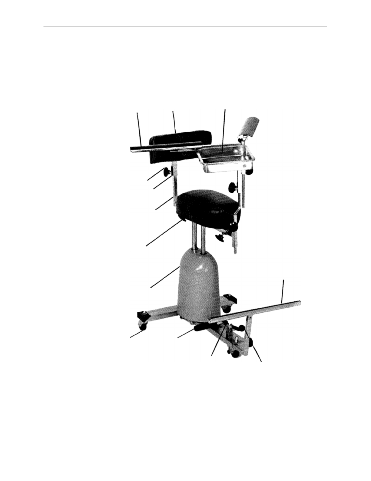
SurgiStool Assembly
763 SurgiStool with ObRound Seat
763–101 SurgiStool with Round Seat
763–201 SurgiStool with Motorcycle Seat
763–10
Arm Rest
Option
24–11 Large Knob
763–3–12 Adjustment Tube Assembly
763–3–1 ”L” Tube Assembly
763–6–1 (ObRound Seat)
763–101–1 Round Seat (not shown)
763–201–29 Motorcycle Seat (not shown) 763–5
763–3–15
Back Rest
763–11
Pan Assembly
Option
Foot Rest
Option
763–1–40 Jack Hood
763–1–37 Caster
763–1–24 Pump Pedal
763–1–35 Brake Clamp
763–20–8
Control Lever Assembly
3
Page 5
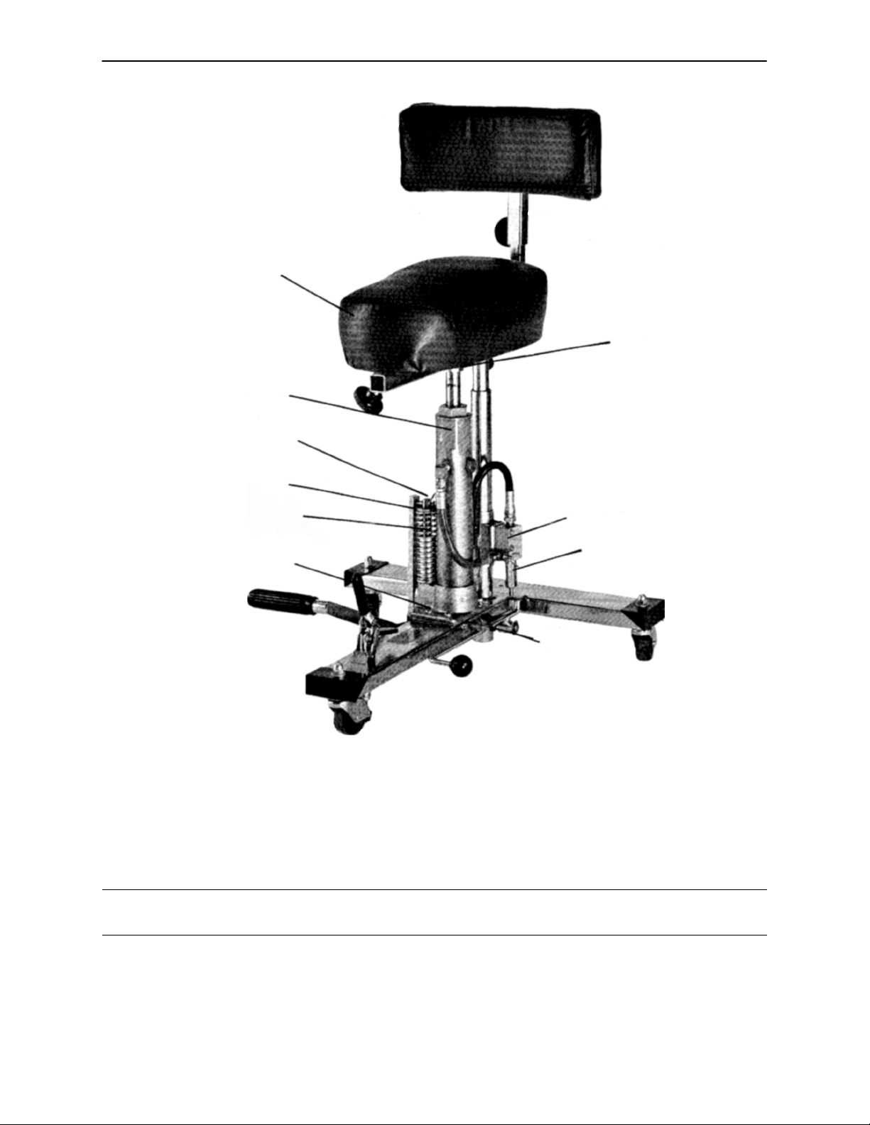
Jack Replacement Instructions
763–6 ObRound Seat & Frame
763–101–2 Round Seat & Frame
763–201–100 Motorcycle Seat & Frame
763–79 Jack Assembly
27–3 Cotter Pin
27–3 Cotter Pin
763–1–19 Pump Link
763–1–15 Jack Spring
4–20 Jack Mounting Screw
763–20–16
Release Pedal Spring
1. Remove the cotter pin at the top of the jack assembly holding the seat frame to the jack.
2. Remove the seat and frame.
3. Remove the two nuts at the bottom of the base and remove the base hood.
4. Remove the manifold from the bracket.
5. Remove the cotter pin in the pump link.
6. Remove the pump link.
Manifold
962–1–52 Release Valve
WARNING
The jack spring is highly compressed. To avoid injury, it must be controlled while the pump link is removed.
7. Remove the jack spring and spring guide.
8. Remove the four jack mounting screws.
9. Remove the jack assembly and use the four mounting screws to install the replacement jack.
10. Reverse steps 1–7 to reassemble the SurgiStool after installing the replacement jack.
4
Page 6

Checking/Adding Hydraulic Fluid
Required Tools:
5/32” Allen Wrench 3/8” Open End Wrench 3/4” Open End Wrench
Needle Nose Pliers
Procedure:
1. Remove the cotter pin at the top of the jack assembly holding the seat frame to the jack.
2. Remove the seat and frame.
3. Remove the two nuts at the bottom of the base and remove the base hood.
4. Be sure there are no hydraulic leaks. If there are, the hydraulic jack must be replaced.
5. Lower the jack to the full down position.
6. Using a 3/4” open end wrench, slowly turn the fill plug located on the side of the reservoir counterclock-
wise to allow excess system pressure to vent. Remove the fill plug.
7. The hydraulic fluid should be visible at the bottom of the fill hole. If it is not, add Mobil Aero HFA hydraulic
fluid (Stryker part number 2020–70–475) until the fluid is visible at the bottom of the fill hole. Replace
the fill plug.
CAUTION
Use of other types of oil may damage hydraulic units.
8. Replace the base hood and the seat assembly.
5
Page 7
AS
AY
AT
AW
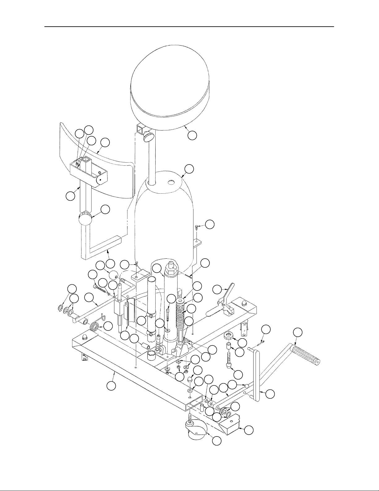
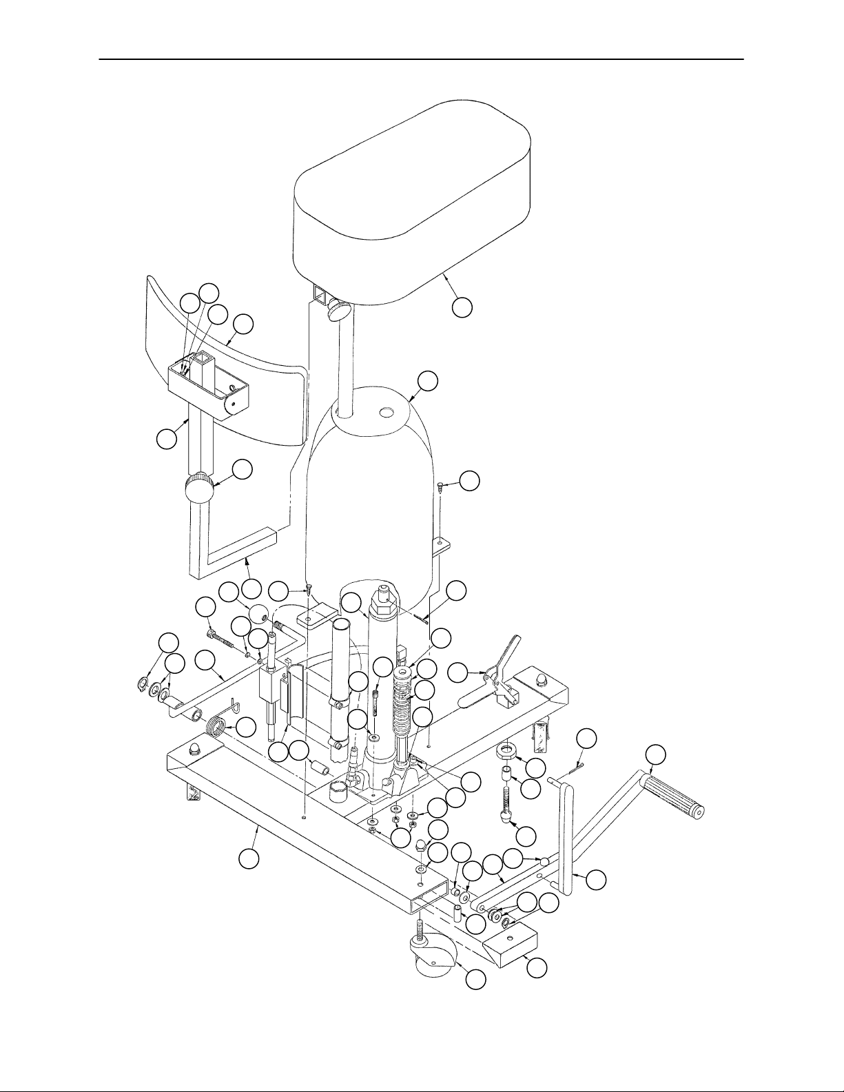
SurgiStool with Round Seat
A
AR
D
BC
BD
BE
BF
F
BL
B
BR
BB
AK
BA
J
K
R
AZ
AA
BA
L
AA
AL
E
T
S
AN
AM
Y
W
Z
AB
AP
N
BH
C
BR
BJ
AJ
BK
P
E
BA
M
AD
H
AC
S
AE
6
Page 8

SurgiStool with Round Seat
Item Part No. Part Name Qty.
A (page 12) Seat & Frame Assembly 1
B24–11 Large Knob 1
C 763–20–1 Base Frame Assembly 1
D 763–1–40 Base Hood 1
E4–20 Soc. Hd. Cap Screw 4
F33–2 Knob 1
H28–95 Retaining Ring 1
J 763–1–14 Spring Guide 1
K 763–1–15 Jack Spring 1
L 763–1–35 Brake Clamp 1
M16–6 Kep Nut 4
N 763–20–16 Spring 1
P (page 16) Jack Assembly 1
R17–6 Acorn Nut 3
S11–4 Washer 3
T 763–1–29 Pedal Spacer 1
W (page 18) Pedal Assembly 1
Y 650–1–48 Rubber Bumper 1
Z 763–1–19 Pump Link Rod Assembly 1
AA 27–3 Cotter Pin 1
AB 763–1–28 Foot Grip 1
AC 763–1–37 Caster 3
AD 763–1–38 Caster Spacer 3
AE 763–1–30 End Cap 3
AF 763–20–45 Name Plate 1
AJ 763–20–21 Hose Sleeve 1
AK 763–1–16 Spring Holder 1
AL 763–1–33 Brake Nut 1
AM 763–1–34 Brake Rubber Stop 1
AN 763–1–36 Brake Spacer 1
AP 763–3–1 “L” Tube Assembly 1
AR (page 19) Back Rest Assembly 1
AS 763–3–12 Adjustment Tube 1
AT 16–3 Fiberlock Nut 2
AW 2–18 Round Hd. Mach. Screw 2
AY 11–11 Nylon Washer 2
AZ 11–67 Flat Washer 3
BA 11–63 Flat Washer 8
BB 390–1–67 Washer 1
BC 28–97 Retaining Ring 1
BD 11–13 Flat Washer 2
BE 763–20–8 Control Lever 1
BF 4–85 Hex Soc. Hd. Cap Screw 2
BH 11–16 Flat Washer 2
BJ 763–20–13 Manifold Mounting Bracket 1
BK 38–15 Adjustable Clamp 2
BL 12–5 Lock Washer 2
BM 921–1–252 Serial Number Label 1
BN 982–1–24 Date–of–Manufacture Label 1
BP 763–1–50 Jack Shim 1
BR 23–42 Self–Tapping Screw 2
7
Page 9
AS
AY
SurgiStool with ObRound Seat
AT
AW
AR
A
D
BC
BD
BF
BE
B
AP
BL
BR
BH
N
AJ
BJ
C
P
BK
BA
E
AK
BB
M
F
BR
AA
J
K
L
AA
AB
BA
R
AZ
BA
E
T
W
S
AD
AL
AN
AM
Y
Z
S
H
AC
AE
8
Page 10

SurgiStool with ObRound Seat
Item Part No. Part Name Qty.
A (page 13) Seat & Frame Assembly 1
B24–11 Large Knob 1
C 763–20–1 Base Frame Assembly 1
D 763–1–40 Base Hood 1
E4–20 Soc. Hd. Cap Screw 4
F33–2 Knob 1
H28–95 Retaining Ring 1
J 763–1–14 Spring Guide 1
K 763–1–15 Jack Spring 1
L 763–1–35 Brake Clamp 1
M16–6 Kep Nut 4
N 763–20–16 Spring 1
P (page 16) Jack Assembly 1
R17–6 Acorn Nut 3
S11–4 Washer 3
T 763–1–29 Pedal Spacer 1
W (page 18) Pedal Assembly 1
Y 650–1–48 Rubber Bumper 1
Z 763–1–19 Pump Link Rod Assembly 1
AA 27–3 Cotter Pin 1
AB 763–1–28 Foot Grip 1
AC 763–1–37 Caster 3
AD 763–1–38 Caster Spacer 3
AE 763–1–30 End Cap 3
AF 763–20–45 Name Plate 1
AJ 763–20–21 Hose Sleeve 1
AK 763–1–16 Spring Holder 1
AL 763–1–33 Brake Nut 1
AM 763–1–34 Brake Rubber Stop 1
AN 763–1–36 Brake Spacer 1
AP 763–3–1 “L” Tube Assembly 1
AR (page 19) Back Rest Assembly 1
AS 763–3–12 Adjustment Tube 1
AT 16–3 Fiberlock Nut 2
AW 2–18 Round Hd. Mach. Screw 2
AY 11–11 Nylon Washer 2
AZ 11–67 Flat Washer 3
BA 11–63 Flat Washer 8
BB 390–1–67 Washer 1
BC 28–97 Retaining Ring 1
BD 11–13 Flat Washer 2
BE (page 20) Control Lever Assembly 1
BF 4–85 Hex Soc. Hd. Cap Screw 2
BH 11–16 Flat Washer 2
BJ 763–20–13 Manifold Mounting Bracket 1
BK 38–15 Adjustable Clamp 2
BL 12–5 Lock Washer 2
BM 921–1–252 Serial Number Label 1
BN 982–1–24 Date–of–Manufacture Label 1
BP 763–1–50 Jack Shim 1
BR 23–42 Self–Tapping Screw 2
9
Page 11

SurgiStool with Motorcycle Seat
AS
AY
AT
AW
BZ
BY
A
CC
AR
BT
AH
B
B
BY
BY
CC
D
BT
BY
BW
CA
A
A
BP
BR
BW
BC
BD
BF
BE
CE
AP
BL
CE
BH
N
BJ
C
P
E
BA
AJ
M
F
AA
J
K
L
AK
BBBK
BA
R
AZ
BA
T
S
AD
AA
AL
E
AM
Y
W
Z
S
H
AB
10
AC
AE
Page 12

SurgiStool with Motorcycle Seat
Item Part No. Part Name Qty.
A 763–201–29 Seat & Mtg. Hardware 1
B24–11 Large Knob 1
C 763–20–1 Base Frame Assembly 1
D 763–1–40 Base Hood 1
E4–20 Soc. Hd. Cap Screw 4
F33–2 Knob 1
H28–95 Retaining Ring 1
J 715–1–133 Spring Guide 1
K 763–1–15 Jack Spring 1
L 763–1–35 Brake Clamp 1
M16–6 Kep Nut 4
N 763–20–16 Spring 1
P (page 16) Jack Assembly 1
R17–6 Acorn Nut 3
S11–4 Washer 3
T 763–1–29 Pedal Spacer 1
W (page 18) Pedal Assembly 1
Y 650–1–48 Rubber Bumper 1
Z 763–1–19 Pump Link Rod Assembly 1
AA 27–3 Cotter Pin 1
AB 763–1–28 Foot Grip 1
AC 763–1–37 Caster 3
AD 763–1–38 Caster Spacer 3
AE 763–1–30 End Cap 3
AF 763–201–30 Name Plate 1
AJ 763–20–21 Hose Sleeve 1
AK 763–1–16 Spring Holder 1
AL 763–1–33 Brake Nut 1
AM 763–1–34 Brake Rubber Stop 1
AP 763–3–1 “L” Tube Assembly 1
AR (page 19) Back Rest Assembly 1
AS 763–3–12 Adjustment Tube 1
AT 16–3 Fiberlock Nut 2
AW 2–18 Round Hd. Mach. Screw 2
AY 11–11 Nylon Washer 2
AZ 11–67 Flat Washer 3
BA 11–63 Flat Washer 8
BB 390–1–67 Washer 1
BC 28–97 Retaining Ring 1
BD 11–13 Flat Washer 2
BE 763–20–8 Control Lever 1
BF 4–85 Hex Soc. Hd. Cap Screw 2
BH 11–16 Flat Washer 2
BJ 763–20–13 Manifold Mounting Bracket 1
BK 38–15 Adjustable Clamp 2
BL 12–5 Lock Washer 2
BM 921–1–252 Serial Number Label 1
BP 12–7 Lock Washer 1
BR 15–13 Hex Nut 1
BT 3–44 Hex Hd. Cap Screw 2
BW 3–20 Hex Hd. Cap Screw 2
BY 11–2 Flat Washer 4
BZ 16–16 Fiberlock Hex Nut 2
CA 763–201–28 U–Bracket 1
CB 763–201–27 Adjustment Plate 2
CC 763–201–24 Pivot Assembly 2
CE 23–42 Self–Tapping Mach. Screw 2
11
Page 13

763–101–2 Round Seat and Frame Assembly
Item Part No. Part Name Qty.
A 763–101–1 Round Seat 1
B24–11 Knob 2
C27–3 Cotter Pin 1
D13–10 Washer 4
E3–4 Hex Hd. Screw 4
F 763–6–2 Seat Frame Assembly 1
12
Page 14

763–6 ObRound Seat and Frame Assembly
Item Part No. Part Name Qty.
A 763–6–1 Seat 1
B24–11 Knob 2
C27–3 Cotter Pin 1
D13–10 Washer 4
E3–4 Hex Hd. Screw 4
F 763–6–2 Seat Frame Assembly 1
13
Page 15

763–79 Jack Assembly
A
W
W
B
B
C
L
12 13/16” Collapsed Height
10” Hydraulic Lift
22 13/16” Open Height
P
J
M
K
C
L
AD
AN
K
AL
D
D
H
S
R
M
N
AK
Y
Z
AB
AC
E
E
S
T
14
Page 16

763–79 Jack Assembly
A
M
J
B
C
F
D
AD
H
AN
K
L
M
N
W
AK
AC
P
R
S
AL
T
R
Z
AB
Y
E
15
Page 17

763–79 Jack Assembly
Item Part No. Part Name Qty.
A45–904 Quad Ring 1
B 390–2–121 Machined Cap 1
C 390–1–243 Gasket 1
D 390–2–137 Pump Cap 1
E (page 17) Jack Base Assembly 1
F 390–2–147 “L” Fitting 1
H 390–2–128 Packing 1
J 388–1–38 Plug 1
K 390–2–135 Pump Piston 1
L 763–20–6 Reservoir 1
M45–110 O–Ring 2
N 390–1–244 Base Gasket 1
P 763–1–48 Actuator Cylinder 1
R 390–2–139 Retaining Collar 2
S 390–2–136 Pump Cylinder 1
T 390–1–237 Pump Gasket 1
W 763–1–49 Actuator 1
Y 926–20–160 Piston End 1
Z 926–20–161 Cup Packing 1
AB 15–13 Hex Jam Nut 1
AC 390–1–233 Actuator Gasket 1
AD 946–1–293 Label 1
AK 926–20–162 Wear Ring 1
AL 45–14 O–Ring 1
AN 36–35 Label 1
AP 763–20–22 Pressure Line (not shown) 1
AR 763–20–23 Return Line (not shown) 1
AS 763–20–34 Relief Valve (not shown) 1
16
Page 18

926–1–295 Jack Base Assembly
Item Part No. Part Name Qty.
A 946–1–291 Jack Base 1
B 926–20–154 Seal 1
C 926–20–153 Check Valve 1
D 926–20–156 Seal 1
E 926–20–159 Valve Plug 1
F 926–20–157 Base Plug 1
H 926–20–155 Seal 1
J 926–20–152 Check Valve 1
K 926–20–158 Reservoir Plug 1
17
Page 19

763–1–24 Pump Pedal Assembly
B
B
A
Item Part No. Part Name Qty.
A 763–1–25 Pedal 1
B81–2 Bearing 2
18
Page 20

763–3–15 Padded Back Rest Assembly
Item Part No. Part Name Qty.
A 763–3–14 Back Rest 1
B 763–3–16 Mounting Bracket 1
C12–12 Lock Washer 2
D2–59 Round Hd. Machine Screw 2
19
Page 21

763–20–8 Control Lever Assembly
Item Part No. Part Name Qty.
A 763–20–9 Control Lever 1
B81–4 Sleeve Bearing 1
20
Page 22

Brake Assembly
C
A
B
Item Part No. Part Name Qty.
A 763–1–35 Clamp 1
B 763–1–33 Nut 1
C 763–1–32 Nut 1
D 763–1–34 Rubber Stop 1
D
21
Page 23

763–20–28 Jack Conversion Kit
Manifold Assembly
of Item
Base Frame
R
P
E
N
W
T
A
S
Z
M
L
D
B
C
D
D
Y
A
Y
DB
F
K
J
H
D
D
22
Page 24

763–20–28 Jack Conversion Kit
Manifold Assembly
of Item
A
N
Assembly Detail
.094 / .099 dia. thru two walls
Bottom surface of
base frame
.010 / .020
8 3/8
1/2
.266 / .271
dia. thru two walls
H J F
D B F
L
K
Base Frame Drilling Detail
for Items A and M
Item Part No. Part Name Qty.
A (page 16) Jack Assembly 1
B4–24 Soc. Hd. Cap Screw 4
C38–15 Adjustable Clamp 2
D11–63 Flat Washer 8
E4–85 Soc. Hd. Cap Screw 2
F16–6 Kep Nut 6
H37–11 Cap 1
J3–2 Hex Hd. Cap Screw 1
K 763–20–24 Bracket 1
L 763–20–26 Pivot Plate Assembly 1
M 763–20–16 Spring 1
N (page 20) Control Lever Assembly 1
P11–13 Flat Washer 1
R28–1 Retaining Ring 1
S 763–20–13 Manifold Mounting Bracket 1
T11–16 Flat Washer 2
W12–15 Lock Washer 2
Y27–3 Cotter Pin 2
Z33–2 Knob 1
23
Page 25

763–10 Optional Accessory Arm Rest Assembly
B
D
A
C
F
E
G
H
J
C
24
Page 26

763–10 Optional Accessory Arm Rest Assembly
Item Part No. Part Name Qty.
A 763–10–15 Arm Rest 2
B 763–10–19 Adaptor 2
C24–11 Large Knob 4
D 763–10–12 Adjustable Main Support 1
E 763–10–7 Main Support 1
F24–53 Fluted Knob 2
G1–19 Machine Screw 4
H 763–10–5 Swivel Bar 1
J 763–10–1 Arm Support Bracket 1
25
Page 27

763–5 Optional Foot Rest Assembly
E
B
D
A
C
F
H
E
Item Part No. Part Name Qty.
A 763–5–1 Lock Block 1
B24–20 Plastic Knob 1
C 763–5–6 Shield 1
D 763–5–3 Foot Support 1
E37–2 Hole Plug 2
F 763–5–2 Lock Pin 1
H2–6 Round Hd. Mach. Screw 1
26
Page 28

European Representative
Stryker France Phone: 33148632290
BP 50040–95946 Roissy Ch. de Gaulle Fax: 33148632175
Cedex–France
6300 Sprinkle Road, Kalamazoo, MI 49001–9799 (800) 327–0770
www.strykermedical.com
DH 7/01 763–20–35 REV C
 Loading...