


Transport Stretcher
747
748
Operations Manual
International - EN | FR | DE | ES | PT | IT
| NL | DA | SV | PL | KO | ZH-CN
2017/05 A.2 0747-109-005 REV A www.stryker.com

sample text

Transport Stretcher
747
748
Operations Manual
2017/05 A.2 0747-109-005 REV A www.stryker.com

sample text
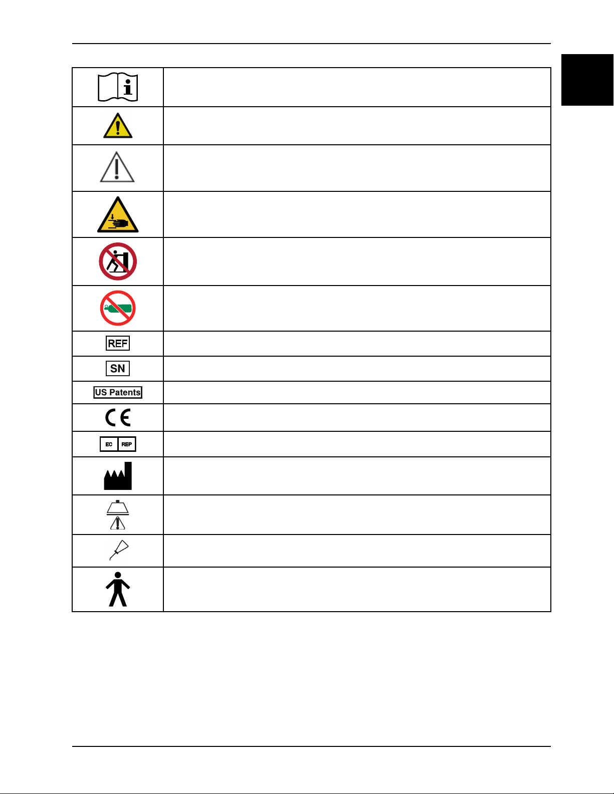
Symbols
Operating instructions
General warning
Caution
Warning; crushing of hands
No pushing
Do not store the oxygen bottle
English
EN
Catalogue number
Serial number
For US Patents see www.stryker.com/patents
CE mark
EC REP
Manufacturer
Safe working load
Lubricate
Type B applied part
www.stryker.com 0747-109-005 REV A

sample text

Table of Contents
Warning/Caution/Note Definition ............................................................................................................... 1-3
Summary of safety precautions................................................................................................................. 1-4
Pinch points .................................................................................................................................... 1-6
Introduction........................................................................................................................................... 1-7
Product description........................................................................................................................... 1-7
Indications for use ............................................................................................................................ 1-7
Expected service life......................................................................................................................... 1-7
Contraindications ............................................................................................................................. 1-7
Specifications.................................................................................................................................. 1-7
Product illustration............................................................................................................................ 1-9
Contact information .......................................................................................................................... 1-9
Serial number location .................................................................................................................... 1-10
Date of manufacture....................................................................................................................... 1-10
Setup................................................................................................................................................. 1-11
Operation ........................................................................................................................................... 1-12
Applying and releasing the brakes ..................................................................................................... 1-12
Raising or lowering the litter.............................................................................................................. 1-12
Positioning the product in Trendelenburg............................................................................................. 1-13
Positioning the product in Reverse Trendelenburg................................................................................. 1-13
Transporting a patient with the retractable fifth wheel ............................................................................ 1-13
Positioning or stowing the push handles (optional) ................................................................................ 1-14
Raising or lowering the siderails ........................................................................................................ 1-14
Raising or lowering the pneumatic Fowler backrest ............................................................................... 1-15
Raising or lowering the gatch............................................................................................................ 1-15
Storing objects in the base hood........................................................................................................ 1-16
Accessories ........................................................................................................................................ 1-17
Attaching the defibrillator tray ........................................................................................................... 1-17
Converting the defibrillator tray/foot extender to a defibrillator tray ........................................................... 1-18
Converting the defibrillator tray/foot extender to a foot extender .............................................................. 1-19
Attaching the footboard/chart holder .................................................................................................. 1-19
Attaching the IV caddy..................................................................................................................... 1-19
Positioning the two-stage permanently attached IV pole option ................................................................ 1-20
Positioning the three-stage permanently attached IV pole option.............................................................. 1-21
Attaching and positioning the removable IV pole ................................................................................... 1-22
Attaching the upright oxygen bottle holder ........................................................................................... 1-23
Extending or stowing the serving tray holder/footboard........................................................................... 1-24
Attaching the siderail pads ............................................................................................................... 1-24
Locating the patient restraint strap tie-ins............................................................................................ 1-24
Cleaning............................................................................................................................................. 1-26
Cleaning the product....................................................................................................................... 1-26
Cleaning the mattress ..................................................................................................................... 1-26
Remove iodine............................................................................................................................... 1-27
Special instructions ........................................................................................................................ 1-27
English
EN
www.stryker.com 0747-109-005 REV A 1-1

Table of Contents
English
EN
Disinfecting......................................................................................................................................... 1-28
Disinfecting the product................................................................................................................... 1-28
Disinfecting the mattress ................................................................................................................. 1-28
Preventive maintenance ........................................................................................................................ 1-30
Lubrication points........................................................................................................................... 1-30
1-2 0747-109-005 REV A www.stryker.com

Warning/Caution/Note Definition
The words WARNING, CAUTION, and NOTE carry special meanings and should be carefully reviewed.
WARNING
Alerts the reader about a situation which, if not avoided, could result in death or serious injury. It may also describe
potential serious adverse reactions and safety hazards.
CAUTION
Alerts the reader of a potentially hazardous situation which, if not avoided, may result in minor or moderate injury to the
user or patient or damage to the product or other property. This includes special care necessary for the safe and
effective use of the device and the care necessary to avoid damage to a device that may occur as a result of use or
misuse.
Note: Provides special information to make maintenance easier or important instructions clearer.
English
EN
www.stryker.com 0747-109-005 REV A 1-3

Summary of safety precautions
English
EN
Always follow the warnings and cautions listed on this page. Service only by qualified personnel.
WARNING
• Always allow the product to reach room temperature before you setup the product or test functional operations.
Permanent product damage may occur.
• Always operate the product when all operators are clear of the mechanisms.
• Always apply the brakes when a patient is getting on the product or off the product or when the product is not
moving. Injury could result if the product moves while a patient is getting on the product or off the product.
• Always put the product in the lowest position with the siderails up and latched when you leave a patient unattended
on the product. Do not leave the product at a higher height.
• Always remove any devices that may be in the way before you raise or lower the litter.
• Do not sit on the end of the product. The product may tip.
• Always keep patient and operator extremities away from collapsed siderails to avoid injury.
• Always unplug the power cord from the wall outlet before you transport or clean the product if your product is
equipped with the electric lift or electric litter option.
• Always lock the siderails in the full up position with the sleep surface flat in the lowest position when you transport a
patient.
• Always put the product in the lowest position with the siderails up and latched when you leave a patient unattended
on the product. Do not leave the product at a higher height.
• Always lock the siderails in the full up position with the sleep surface horizontal in the lowest position when you
transport a patient.
• Always keep the patient’s limbs away from the siderail spindles when you lower the siderail.
• Do not allow the siderails to lower on their own.
• Always keep hands and fingers clear of the Fowler backrest release handles and the Fowler backrest frame when
you lower the Fowler backrest.
• Always use caution when you raise a pneumatic Fowler backrest while a patient is on the product. Use proper lifting
techniques and get assistance, if necessary.
• Do not place items that weigh more than 30 lb (14 kg) on the defibrillator tray. Always strap down all devices that
you place on the defibrillator tray.
• Always use caution if the defibrillator tray/foot extender, footboard/chart holder, or upright oxygen bottle holder is
attached to avoid pinching your fingers when you position the foot end push handle option.
• Do not place items that weigh more than 30 lb (14 kg) on the defibrillator tray/foot extender. Always strap down all
devices that you place on the defibrillator tray.
• Always secure the IV pole to the IV caddy when you transport the product.
• Always store the IV caddy when not in use to avoid product damage.
• Do not use the IV pole as a push/pull device. Product damage may occur.
• Do not place objects that exceed 40 lb (18 kg) in the upright oxygen bottle holder.
• Do not place objects that exceed 30 lb (14 kg) on the serving tray.
• Always use caution when you attach restraint straps. Patient or operator injury may occur. Physical restraints, even
if secured, may result in serious harm to patients and operators, including entanglement, entrapment, physical injury,
or death.
• Always attach restraint straps or devices only at the identified attachment points of the product. Failure to do so
may result in patient or operator injury. Do not attach restraints straps to the siderail.
• Always refer to the applicable state and federal restrictions and regulations and the appropriate facility protocols
before you use any restraint strap or device.
• Do not clean, service, or perform maintenance while the product is in use.
1-4 0747-109-005 REV A www.stryker.com

Summary of safety precautions
WARNING (CONTINUED)
• Do not immerse the mattress in cleaning or disinfectant solutions. Excess moisture could cause product
malfunction that results in product damage or patient injury.
• Do not allow fluid to pool on the mattress. Fluids can cause corrosion of components and may cause the safety and
performance of this product to become unpredictable.
• Always inspect mattress covers for tears, punctures, excessive wear, and misaligned zippers every time you clean
the covers. Remove and replace a damaged mattress immediately to prevent cross-contamination.
• Do not steam clean, pressure wash, hose off, or ultrasonically clean mattresses. These methods of cleaning may
void this product’s warranty.
• Always disinfect the mattress between patients. Failure to do so could result in cross-contamination and infection.
CAUTION
• Improper usage of the product can cause injury to the patient or operator. Operate the product only as described in
this manual.
• Do not modify the product or any components of the product. Modifying the product can cause unpredictable
operation resulting in injury to patient or operator. Modifying the product also voids its warranty.
• Do not use the hydraulics on the base to raise the product with a patient lift under the product.
• Do not place objects that exceed 60 lb (27 kg) in the base hood.
• Do not sit, step, or stand on the base hood.
• Always raise the IV pole before you attach the defibrillator tray/foot extender to the product. If you do not raise the
IV pole, the foot extender will not operate.
English
EN
www.stryker.com 0747-109-005 REV A 1-5
Summary of safety precautions
English
EN
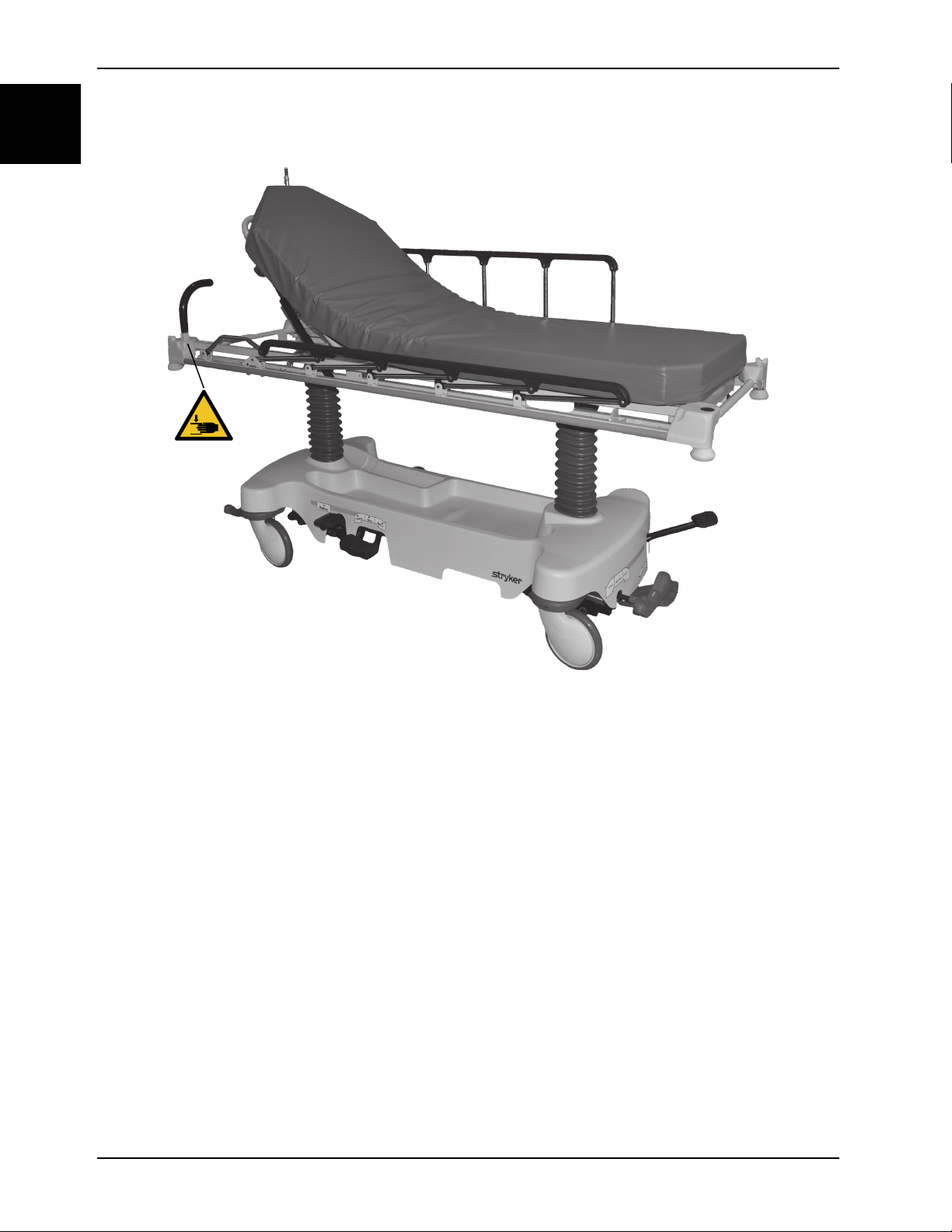
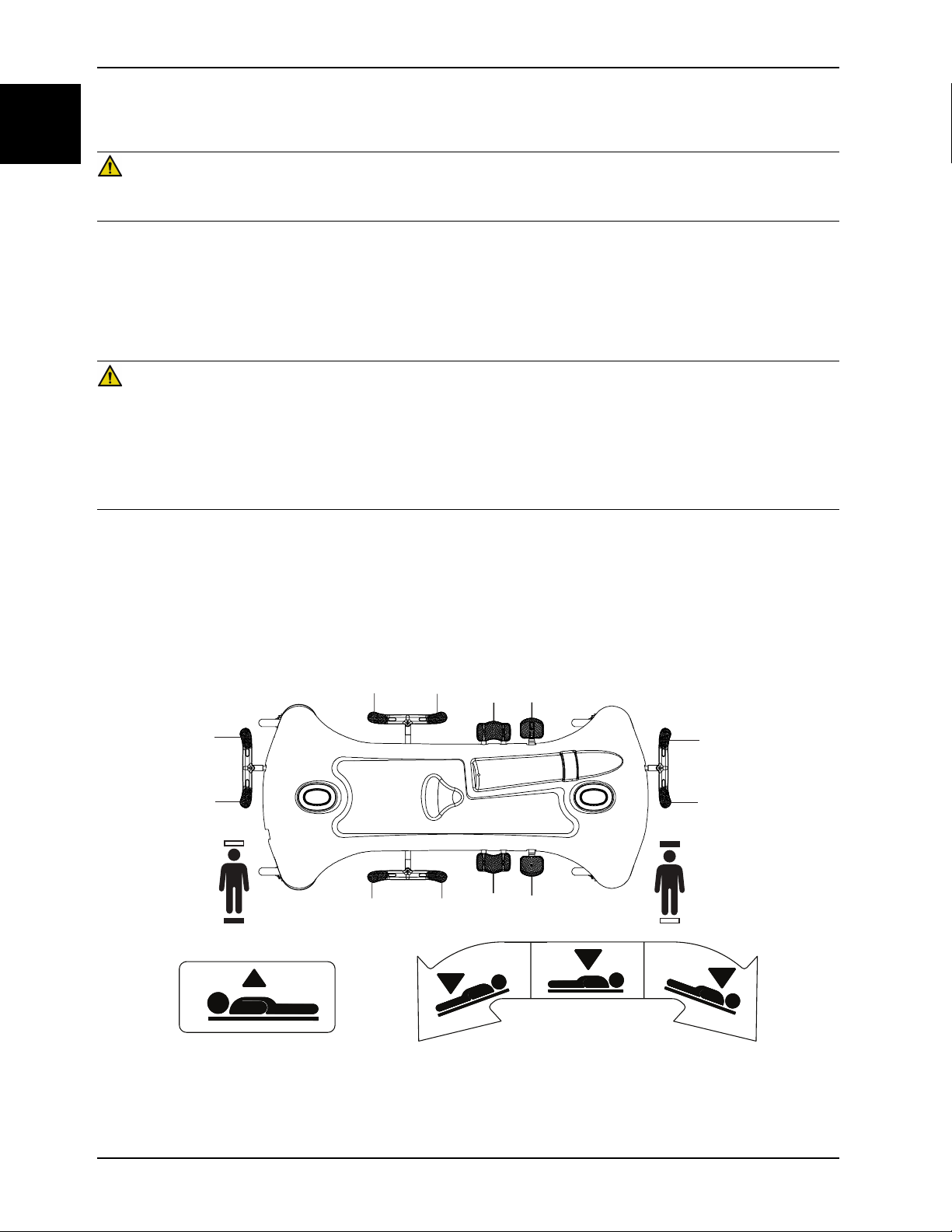
Pinch points
Figure 1-1: Pinch points
1-6 0747-109-005 REV A www.stryker.com

Introduction
This manual assists you with the operation or maintenance of your Stryker product. Read this manual before operating
or maintaining this product. Set methods and procedures to educate and train your staff on the safe operation or
maintenance of this product.
CAUTION
• Improper usage of the product can cause injury to the patient or operator. Operate the product only as described in
this manual.
• Do not modify the product or any components of the product. Modifying the product can cause unpredictable
operation resulting in injury to patient or operator. Modifying the product also voids its warranty.
Notes
• This manual is a permanent part of the product and should remain with the product even if the product is sold.
• Stryker continually seeks advancements in product design and quality. This manual contains the most current
product information available at the time of printing. There may be minor discrepancies between your product and
this manual. If you have any questions, contact Stryker Customer Service or Technical Support at 1-800-327-0770.
Product description
The Stryker Model 747/748 Transport Stretcher is a general purpose patient transport and treatment stretcher.
Indications for use
English
EN
The Stryker Model 747/748 Transport Stretcher is a non-powered, wheeled device which consists of a platform
mounted on a wheeled frame that is designed to support patients in a horizontal position. The device has siderails and
has the option available to support the temporary or permanent placement of I.V. poles. A stretcher provides the
operator a method of transporting patients within a healthcare facility. Some stretchers may also be used for minor
procedures and short-term stay (treatment and recovery).
Expected service life
The Transport Stretcher has a 10 year expected service life under normal use conditions and with appropriate periodic
maintenance.
Contraindications
None known.
Specifications
Model 747 Transport Stretcher Model 748 Transport Stretcher (wide)
HT Packs
Safe working load
indicates the sum of the
patient, mattress and
accessory weight
500 lb 225 kg 500 lb 225 kg
Overall length
www.stryker.com 0747-109-005 REV A 1-7
83 in. 210.8 cm 83 in. 210.8 cm

Introduction
English
EN
Specifications (Continued)
Overall width
Height
High 36 in. 91.4 cm 36 in. 91.4 cm
Low 21.5 in. 54.6 cm 21.5 in. 54.6 cm
Patient surface
Siderails
Litter positioning
Backrest 0° to 90° 0° to 90°
Knee gatch Not applicable 0° to 30°
Trendeleburg/
Reverse
Trendelenburg
Caster diameter
Minimum under product
clearance
30 in. 76.2 cm 34 in. 86.4 cm
26 in. x 75.5 in. 66 cm x 192 cm 30 in. x 75.5 in. 76 cm x 192 cm
13 in. x 55 in. 33 cm x 139.5 cm 13 in. x 55 in. 33 cm x 139.5 cm
+18° / -18° +18° / -18°
8 in. 20 cm 8 in. 20 cm
6 in. nominal
1.75 in. under the
hydraulic cylinders
and fifth wheel
15 cm
4.5 cm
6 in. nominal
1.75 in. under the
hydraulic cylinders
and fifth wheel
15 cm
4.5 cm
Stryker reserves the right to change specifications without notice.
1-8 0747-109-005 REV A www.stryker.com
Introduction
A
B
C
E
B
D
D
E
F
F
A
A
A
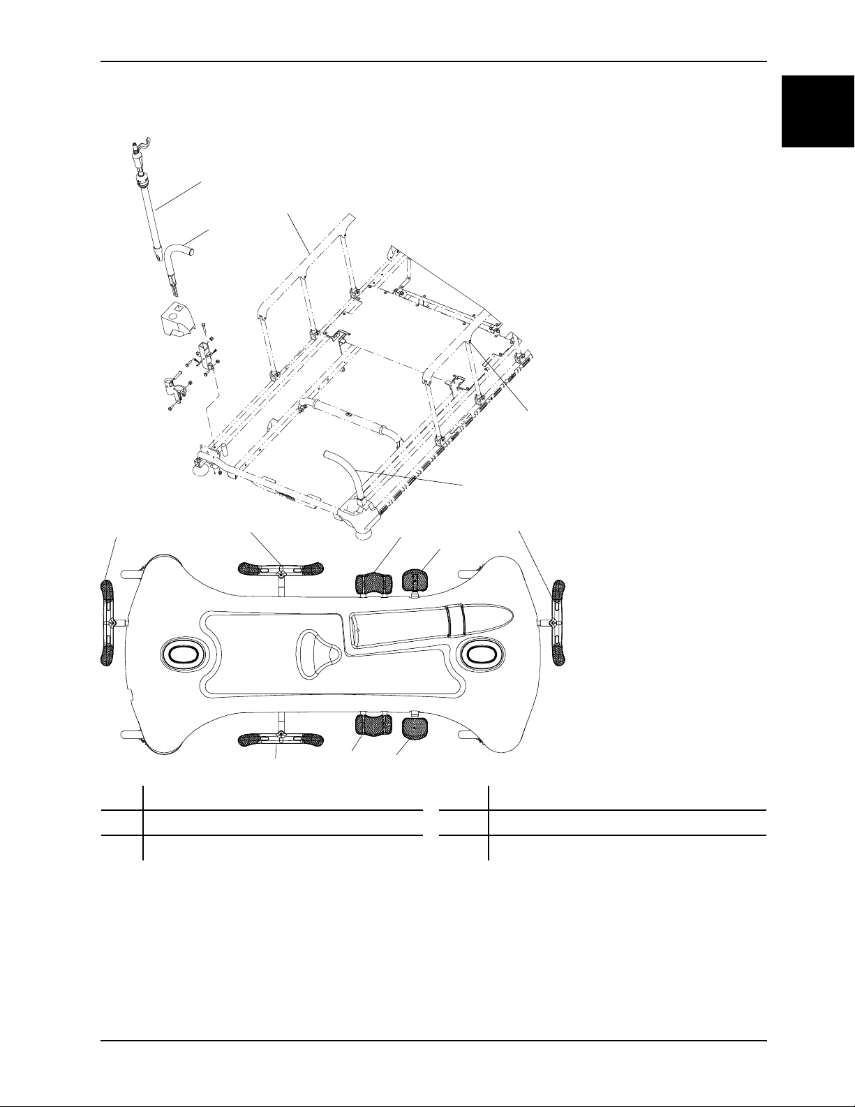
Product illustration
English
EN
A
B
C
Brake/steer pedal
Head end push handle
IV pole
Contact information
D
E
F Siderail
Lowering pedal
Pump pedal
Contact Stryker Customer Service or Technical Support at: 1-800-327-0770.
www.stryker.com 0747-109-005 REV A 1-9
Introduction
A
English
EN
Contact information (Continued)
Stryker Medical
3800 E. Centre Avenue
Portage, MI 49002
USA
To view your operations or maintenance manual online, see https://techweb.stryker.com/.
Have the serial number (A) of your Stryker product available when calling Stryker Customer Service or Technical
Support. Include the serial number in all written communication.
Serial number location
Date of manufacture
The year of manufacture is the first 2 digits of the serial number.
1-10 0747-109-005 REV A www.stryker.com

Setup
To unpack your product, see the unpacking instructions that are attached to the product inside of the shipping crate.
WARNING
• Always allow the product to reach room temperature before you setup the product or test functional operations.
Permanent product damage may occur.
• Always operate the product when all operators are clear of the mechanisms.
Make sure that the product is working before the product is put into service.
1. Apply the brakes. Push on the product to make sure that all four casters are locked.
2. Raise and lower the hydraulic lift system.
3. Raise the product to the highest height and put the product in the Trendelenburg position. Make sure that the head
end lowers to the lowest position.
4. Raise the product to the highest height and put the product in the Reverse Trendelenburg position. Make sure that
the foot end lowers to the lowest position.
5. Apply the fifth wheel to make sure that it guides and pivots the product.
6. Make sure that the siderails raise, lower, and lock in place.
7. Raise and lower the Fowler backrest.
English
EN
www.stryker.com 0747-109-005 REV A 1-11
Operation
B
A
B
A
B
A
A
B
A
B
C
D
C
D
English
EN
Applying and releasing the brakes
WARNING
Always apply the brakes when a patient is getting on the product or off the product or when the product is not moving.
Injury could result if the product moves while a patient is getting on the product or off the product.
To apply the brakes, push down on the brake (red) side of the brake/steer pedal. Push on the product to make sure that
the brakes work.
To release the brakes, push down on the steer (green) side of the brake/steer pedal.
Raising or lowering the litter
WARNING
• Always put the product in the lowest position with the siderails up and latched when you leave a patient unattended
on the product. Do not leave the product at a higher height.
• Always remove any devices that may be in the way before you raise or lower the litter.
• Do not sit on the end of the product. The product may tip.
• Always keep patient and operator extremities away from collapsed siderails to avoid injury.
To raise the litter, pump the pump pedal (D) until you achieve the desired height (Figure 1-2 on page 1-12).
To lower the entire litter, press on the center of the uni-lower pedal (C).
To lower the head end of the litter, press on the side of the uni-lower pedal (C) closest to the head end of the product.
To lower the foot end of the litter, press on the side of the uni-lower pedal (C) closest to the foot end of the product.
1-12 0747-109-005 REV A www.stryker.com
Figure 1-2: Raising or lowering the litter

Operation
Positioning the product in Trendelenburg
WARNING
Always remove any devices that may be in the way before you raise or lower the litter.
CAUTION
Do not use the hydraulics on the base to raise the product with a patient lift under the product.
To position the product in the Trendelenburg position (head down), raise the litter to the highest height (Figure 1-2 on
page 1-12).
Note: Raise the litter to the highest height for a greater Trendelenburg angle.
To put the product in Trendelenburg position, push down on the side of the uni-lower pedal closest to the head end (C).
To lower the product from Trendelenburg position, push down on the center of the uni-lower pedal (C) until the litter is
flat.
Positioning the product in Reverse Trendelenburg
WARNING
Always remove any devices that may be in the way before you raise or lower the litter.
English
EN
CAUTION
Do not use the hydraulics on the base to raise the product with a patient lift under the product.
To position the product in the Reverse Trendelenburg position (foot down), raise the litter to the highest height (Figure 1-
2 on page 1-12)
To put the product in the Reverse Trendelenburg position, push down on the side of the uni-lower pedal closest to the
foot end (C).
To lower the product from Reverse Trendelenburg position, push down on the center of the uni-lower pedal (C) until the
litter is flat.
Transporting a patient with the retractable fifth wheel
WARNING
• Always position the patient in the center of the product.
• Always remove any devices that may be in the way before you raise or lower the litter.
• Always unplug the power cord from the wall outlet before you transport or clean the product if your product is
equipped with the electric lift or electric litter option.
• Always lock the siderails in the full up position with the sleep surface flat in the lowest position when you transport a
patient.
CAUTION
Do not use the hydraulics on the base to raise the product with a patient lift under the product.
www.stryker.com 0747-109-005 REV A 1-13
Operation
English
EN
Transporting a patient with the retractable fifth wheel (Continued)
To transport a patient with the retractable fifth wheel:
1. Push down on the steer side of the brake/steer pedal to apply the fifth wheel.
2. Put the pedal in the neutral position to move the product laterally. Move the product to the desired location.
Note: Do not attempt to move the product laterally with the retractable fifth wheel applied.
3. Apply the brakes to lock the product in place.
Note: Always make sure that the brake is released before you move the product to avoid operator or patient injury.
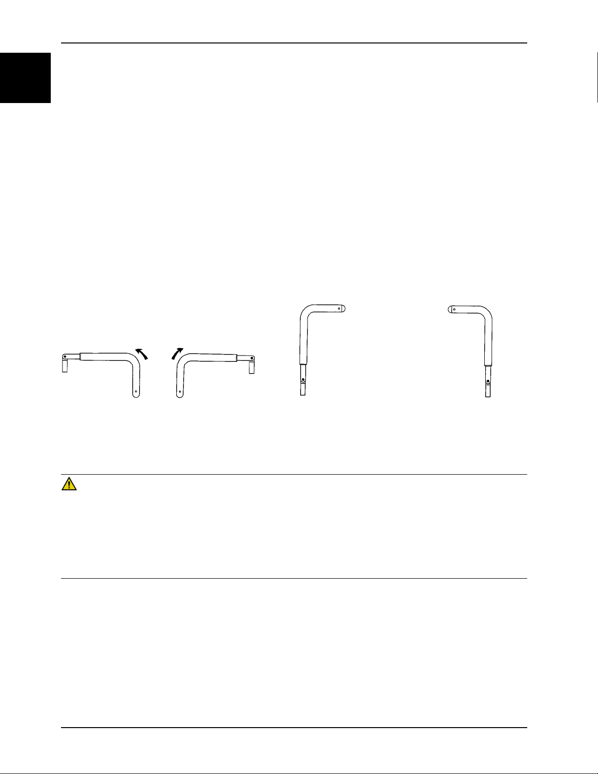
Positioning or stowing the push handles (optional)
To position or stow the push handles:
1. Pivot the handles up from the end of the product (Figure 1-3 on page 1-14).
2. Push down on the handles to lock them into position.
3. Reverse steps to stow the handles.
Note: Only use the push handles as push or pull devices unless otherwise specified to avoid product damage.
Figure 1-3: Positioning the head end push handles
Raising or lowering the siderails
WARNING
• Always put the product in the lowest position with the siderails up and latched when you leave a patient unattended
on the product. Do not leave the product at a higher height.
• Always lock the siderails in the full up position with the sleep surface horizontal in the lowest position when you
transport a patient.
• Always keep the patient’s limbs away from the siderail spindles when you lower the siderail.
• Do not allow the siderails to lower on their own.
To raise the siderails, use two hands to grasp the siderail. Raise the siderail until the release latch clicks into place. Pull
on the siderail to make sure that the siderail is locked.
To lower the siderails, pull up on the release latch. Guide the siderail to the lowest position.
Note: Do not use siderails as restraint devices to keep the patient from exiting the product. The siderails keep the
patient from rolling off the product. The operator must determine the degree of restraint necessary to make sure that the
patient is safe.
1-14 0747-109-005 REV A www.stryker.com
Operation
A
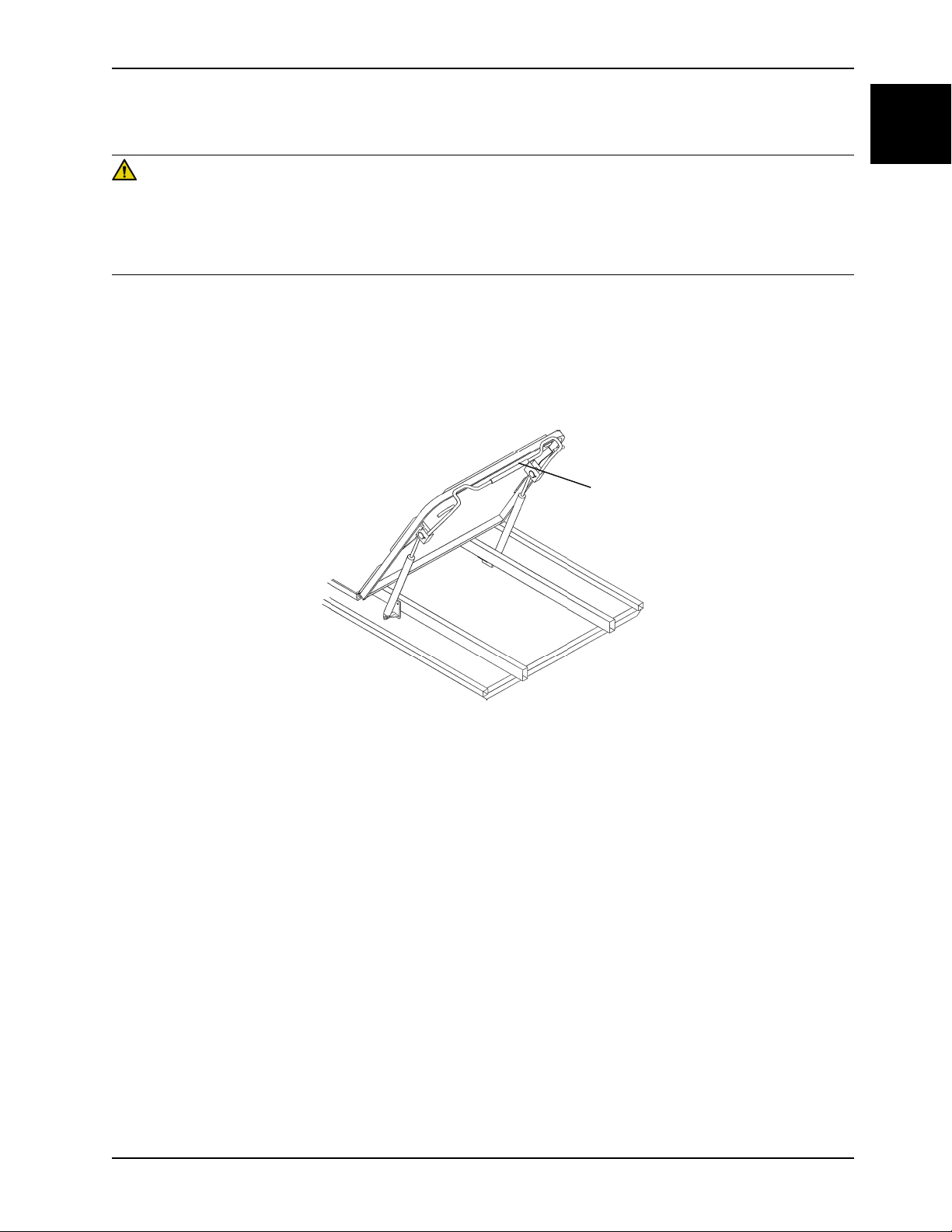
Raising or lowering the pneumatic Fowler backrest
WARNING
• Always keep hands and fingers clear of the Fowler backrest release handles and the Fowler backrest frame when
you lower the Fowler backrest.
• Always use caution when you raise a pneumatic Fowler backrest while a patient is on the product. Use proper lifting
techniques and get assistance, if necessary.
To raise the Fowler backrest, squeeze the red Fowler backrest release handle (A) and pull the Fowler backrest up to
the desired position (Figure 1-4 on page 1-15).
To lower the Fowler backrest:
1. Squeeze the Fowler backrest release handle (A).
2. Push the Fowler backrest down to the desired position.
English
EN
Figure 1-4: Pneumatic Fowler
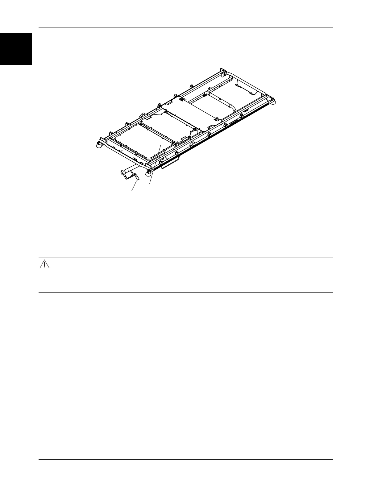
Raising or lowering the gatch
To raise the gatch (B), turn the crank handle (A) clockwise (Figure 1-5 on page 1-16).
www.stryker.com 0747-109-005 REV A 1-15
Operation
A
B
English
EN
Raising or lowering the gatch (Continued)
Figure 1-5: Gatch and crank handle
To lower the gatch (B), turn the crank handle (A) counterclockwise.
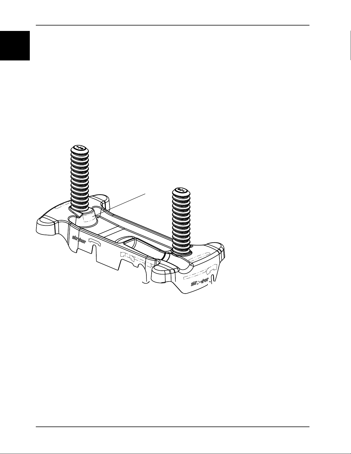
Storing objects in the base hood
CAUTION
• Do not place objects that exceed 60 lb (27 kg) in the base hood.
• Do not sit, step, or stand on the base hood.
You can store patient belongings in the base hood. Do not use the oxygen bottle holder cutout to store oxygen bottles or
patient belongings.
1-16 0747-109-005 REV A www.stryker.com

Accessories
These accessories may be available for use with your product. Confirm availability for your configuration or region. Call
Stryker Customer Service: 1-800-327-0770.
Name Part number
Defibrillator tray
Defibrillator tray/foot extender/footboard
Footboard/chart holder 1105-045-500
IV caddy 0785-155-000
IV pole, removable 0390-025-010
Oxygen bottle retainer
Oxygen bottle holder, upright
Restraint strap, ankle 0946-043-001
Restraint strap, body 0390-019-000
Restraint strap, chest 1010-058-000
Restraint strap, full package
Restraint strap, wrist 0946-044-001
Serving tray
1105-045-200
1105-045-400
1037-010-090
1115-130-000
1010-077-000
1105-045-700
English
EN
Serving tray holder/footboard
Siderail pad set
1105-045-800
1010-052-000
Attaching the defibrillator tray
WARNING
• Do not place items that weigh more than 30 lb (14 kg) on the defibrillator tray. Always strap down all devices that
you place on the defibrillator tray.
• Always use caution if the defibrillator tray/foot extender, footboard/chart holder, or upright oxygen bottle holder is
attached to avoid pinching your fingers when you position the foot end push handle option.
To attach the defibrillator tray:
1. Insert the defibrillator tray pins into the sockets at the foot end of the product.
2. Use the strap to secure devices to the defibrillator tray.
Notes
• Do not use the defibrillator tray as a push/pull device. Product damage may occur.
• Always raise the foot end push handles when you use accessories (such as the defibrillator tray/foot extender,
footboard/chart holder, upright oxygen bottle holder) or the accessories will not function.
www.stryker.com 0747-109-005 REV A 1-17
Accessories
A
B
C
D
English
EN
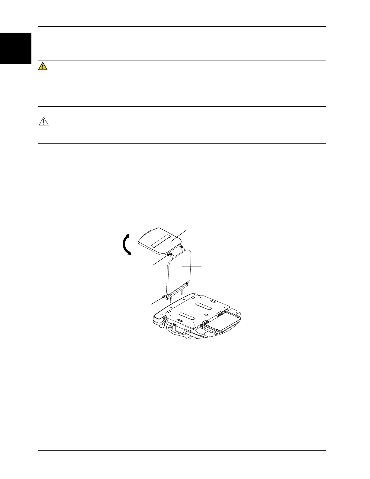
Converting the defibrillator tray/foot extender to a defibrillator tray
WARNING
• Do not place items that weigh more than 30 lb (14 kg) on the defibrillator tray/foot extender. Always strap down all
devices that you place on the defibrillator tray.
• Always use caution if the defibrillator tray/foot extender, footboard/chart holder, or upright oxygen bottle holder is
attached to avoid pinching your fingers when you position the foot end push handle option.
CAUTION
Always raise the IV pole before you attach the defibrillator tray/foot extender to the product. If you do not raise the IV
pole, the foot extender will not operate.
To convert the defibrillator tray/foot extender to a defibrillator tray:
1. Pull out the top knob (A) (Figure 1-6 on page 1-18).
2. Pivot the defibrillator tray (B) until the tray is flat over the foot end of the product. Release the top knob (A). Make
sure that the defibrillator tray is locked in place.
3. Use the strap to secure devices to the defibrillator tray.
Notes
• Do not use the defibrillator tray/foot extender as a push/pull device. Product damage may occur.
• Do not attach items to the foot extender.
Figure 1-6: Defibrillator tray/foot extender
1-18 0747-109-005 REV A www.stryker.com

Accessories
Converting the defibrillator tray/foot extender to a foot extender
WARNING
• Do not place items that weigh more than 30 lb (14 kg) on the defibrillator tray/foot extender. Always strap down all
devices that you place on the defibrillator tray.
• Always use caution if the defibrillator tray/foot extender, footboard/chart holder, or upright oxygen bottle holder is
attached to avoid pinching your fingers when you position the foot end push handle option.
CAUTION
Always raise the IV pole before you attach the defibrillator tray/foot extender to the product. If you do not raise the IV
pole, the foot extender will not operate.
To convert the defibrillator tray/foot extender to a foot extender (Figure 1-6 on page 1-18):
1. Pull out the top knob (A).
2. Pivot the defibrillator tray (B) until the tray locks against the foot extender.
3. Pull out the bottom knob (D) while you hold the defibrillator tray/foot extender assembly.
4. Lower the foot extender (C) until the foot extender is flat.
5. Release the bottom knob (D). Push on the foot extender to make sure that the foot extender is locked in place.
Notes
• Do not use the defibrillator tray/foot extender as a push/pull device. Product damage may occur.
• Do not attach items to the foot extender.
English
EN
Attaching the footboard/chart holder
WARNING
Always use caution if the defibrillator tray/foot extender, footboard/chart holder, or upright oxygen bottle holder is
attached to avoid pinching your fingers when you position the foot end push handle option.
To attach the footboard/chart holder, insert the footboard/chart holder pins into the sockets at the foot end of the
product.
Note: Do not use the footboard/chart holder as a push/pull device. Product damage may occur.
Attaching the IV caddy
WARNING
• Always secure the IV pole to the IV caddy when you transport the product.
• Always store the IV caddy when not in use to avoid product damage.
To attach the IV caddy (Figure 1-7 on page 1-20):
1. Lift the IV caddy out of the storage tray or from the storage clip.
2. Pivot the IV caddy to the desired position.
3. Turn the knob (A) counterclockwise to loosen the pole clamp (C).
4. Pivot the knob (A) away from the arm connection assembly (B).
5. Open the clamp (C).
6. Place the IV pole into the clamp (C).
www.stryker.com 0747-109-005 REV A 1-19
Accessories
AB
C
English
EN
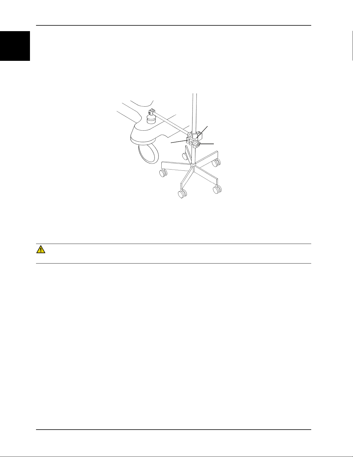
Attaching the IV caddy (Continued)
7. Close the clamp (C) around the IV pole and pivot the knob (A) into position.
8. Turn the knob (A) clockwise to tighten the knob.
9. Reverse steps to disconnect the IV caddy from the product.
To store the IV caddy, place the IV caddy in the storage tray or secure the caddy in the storage clip.
Figure 1-7: IV caddy
Positioning the two-stage permanently attached IV pole option
WARNING
Do not use the IV pole as a push/pull device. Product damage may occur.
You can purchase the product with the two-stage IV pole option permanently attached at the head end, foot end, or both
ends of the product. The IV pole is equipped with a telescopic pole that extends to provide a second height position. You
can fold and store the IV pole when not in use.
To position the two-stage IV pole (Figure 1-8 on page 1-21):
1. Lift and pivot the pole from the storage position.
2. Push the IV pole down until the IV pole locks in place.
3. To raise the height of the IV pole, pull up on the telescoping portion (A) until the pole locks in place at the fully
raised position.
4. Rotate the IV hangers (B) to the desired position and hang the IV bags.
5. To lower the IV pole, hold the telescoping portion of the IV pole, turn the latch (C), and lower the telescoping portion.
Notes
• Do not hang IV bags that exceed 40 lb (18 kg) on the IV pole.
• Always make sure that the IV pole is at a low height to pass safely through door openings when you transport a
patient.
1-20 0747-109-005 REV A www.stryker.com

Accessories
A
B
C
A
Positioning the two-stage permanently attached IV pole option (Continued)
Figure 1-8: Positioning the 2 stage permanently attached IV pole
English
EN
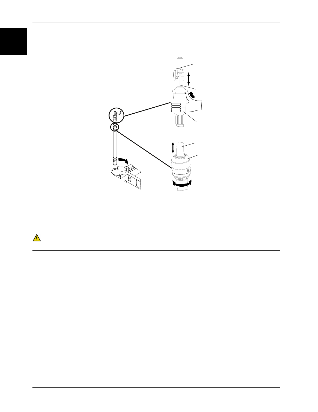
Positioning the three-stage permanently attached IV pole option
WARNING
Do not use the IV pole as a push/pull device. Product damage may occur.
You can purchase the product with the three-stage IV pole option permanently attached at the head end, foot end, or
both ends of the product. The IV pole is equipped with a telescopic pole that extends to provide a second and third
height position. You can also fold and store the IV pole when not in use.
To position the three-stage IV pole (Figure 1-9 on page 1-22):
1. Lift and pivot the pole from the storage position.
2. Push the IV pole down until the pole locks in place.
3. To raise the height of the IV pole, pull up on the telescoping portion (A) until the pole locks into place at the fully
raised position.
4. For a higher IV pole, pull up on section (B). Release section (B) at any desired height to lock the pole in place.
5. Rotate the IV hangers (C) to the desired position and hang the IV bags.
6. To lower the IV pole, push up on the yellow portion of the grip (D) while holding on to section (B) until the pole
lowers.
7. Turn the latch (E) and lower the IV pole telescoping portion.
Notes
• Do not hang IV bags that exceed 12 lb (5 kg) total for all bags on the IV pole.
• Do not hang IV bags that exceed 9.3 lb (4.2 kg) on a single IV hanger.
• Always make sure that the IV pole is at a low height to allow the pole to pass safely through door openings
when you transport a patient.
www.stryker.com 0747-109-005 REV A 1-21
Accessories
A
E
C
B
D
English
EN
Positioning the three-stage permanently attached IV pole option (Continued)
Figure 1-9: Positioning the three-stage permanently attached IV pole
Attaching and positioning the removable IV pole
WARNING
Do not use the IV pole as a push/pull device. Product damage may occur.
To attach and position the removable IV pole (Figure 1-10 on page 1-23):
1. Insert the IV pole into a socket at the head end or foot end of the product.
2. Turn the knob (A) counterclockwise and pull up on the telescoping portion (B) until you reach the desired height.
3. Turn the knob (A) clockwise to lock the telescoping portion in place.
Notes
• Do not hang IV bags that exceed 40 lb (18 kg) on the IV pole.
• Always make sure that the IV pole is at a low height to pass through door openings when you transport a patient.
1-22 0747-109-005 REV A www.stryker.com
Accessories
A
B
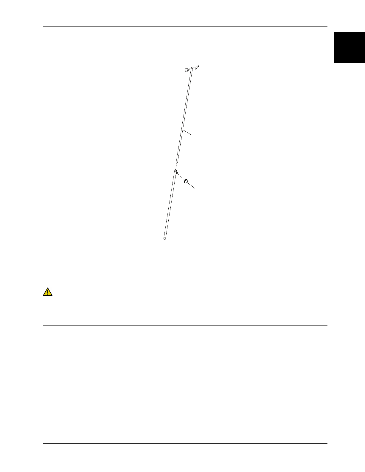
Attaching and positioning the removable IV pole (Continued)
English
EN
Figure 1-10: Removable IV pole
Attaching the upright oxygen bottle holder
WARNING
• Do not place objects that exceed 40 lb (18 kg) in the upright oxygen bottle holder.
• Always use caution if the defibrillator tray/foot extender, footboard/chart holder, or upright oxygen bottle holder is
attached to avoid pinching your fingers when you position the foot end push handle option.
The upright oxygen bottle holder supports an oxygen bottle in a vertical position.
To attach the upright oxygen bottle holder:
1. Insert the support bar into any of the IV sockets.
2. Insert the cotter pin through the hole in the support bar to secure the bottle holder to the product.
Note: Do not use the upright oxygen bottle holder as a push/pull device.
www.stryker.com 0747-109-005 REV A 1-23

Accessories
English
EN
Extending or stowing the serving tray holder/footboard
WARNING
Do not place objects that exceed 30 lb (14 kg) on the serving tray.
To fit the serving tray on the siderail, pull out on both sides of the serving tray and position the tray over the siderails.
To stow the serving tray:
1. Remove the serving tray from the siderails.
2. Push in the sides of the serving tray.
3. Store the serving tray in the footboard.
Note: Do not use the serving tray/footboard as a push/pull device.
Attaching the siderail pads
To attach the siderail pads:
1. Tuck the siderail pad between the mattress and the siderail.
2. Fasten the Velcro® straps around the top of the siderail to secure the siderail pad.
Locating the patient restraint strap tie-ins
WARNING
• Always use caution when you attach restraint straps. Patient or operator injury may occur. Physical restraints, even
if secured, may result in serious harm to patients and operators, including entanglement, entrapment, physical injury,
or death.
• Always attach restraint straps or devices only at the identified attachment points of the product. Failure to do so
may result in patient or operator injury. Do not attach restraints straps to the siderail.
• Always refer to the applicable state and federal restrictions and regulations and the appropriate facility protocols
before you use any restraint strap or device.
There are eight patient restraint strap tie-in locations on the litter assembly for attaching patient restraint straps (Figure
1-11 on page 1-25).
1-24 0747-109-005 REV A www.stryker.com
 Loading...