


Power-LOAD® Cot Fastener System
6390
Maintenance Manual
2017/09 D.2 6390-009-002 REV D www.stryker.com

sample text
Symbols
Refer to instruction manual/booklet
Operating instructions/Consult instructions for use
CE mark
EC REP
General warning
Caution
Warning; crushing of hands
Warning; non-ionizing radiation
Catalogue number
Lot (batch) code
Serial number
For US Patents see www.stryker.com/patents
Manufacturer
Date of manufacture
Safe working load
Dangerous voltage
Medical Equipment Recognized by Underwriters Laboratories LLC With Respect to Electric
Shock, Fire, and Mechanical Hazards only in accordance with ANSI/AAMI ES60601-1:2012
and CAN/CSA-C22.2 No. 60601-1:14.
Direct current
Class II electrical equipment: equipment in which protection against electric shock does not
rely on basic insulation only, but in which additional safety precautions such as double
insulation or reinforced insulation are provided, there being no provision for protective earthing
or reliance upon installation conditions
www.stryker.com 6390-009-002 REV D
Symbols
5
1122VV
U.S.A.
TRA
Registered No:
ER35122/14
Dealer No:
DA35173/14
50
In accordance with European Directive 2012/96/EC on Waste Electrical and Electronic
Equipment, this symbol indicates that the product must not be disposed of as unsorted
municipal waste, but should be collected separately. Refer to your local distributor for return
or collection systems available in your country.
In accordance with European Directive 2002/96/EC on Waste Electrical and Electronic
Equipment, this symbol indicates that the product must not be disposed of as unsorted
municipal waste, but should be collected separately. Refer to your local distributor for return
or collection systems available in your country.
IPX6
Protection from powerful water jets
This device complies with Part 18 of the FCC Rules
Two person lift
This way up
Fragile, handle with care
Keep dry
Do not stack more than 5 high
12 VDC battery powered
Fuse
Battery duty cycle (loading): 10.0% (less than 33 seconds on, more than 300 seconds off)
Battery duty cycle (charging): 100%
English text below this symbol is intended for USA audiences only.
Registered in United Arab Emirates by the Telecommunications Regulatory Authority
Product complies with applicable EMC standards in Australia/New Zealand
Approved by independent communications authority of South Africa
6390-009-002 REV D www.stryker.com

Symbols
Box manufacturer’s certificate - this packaging box has minimum edge crush test value of 82
lbs/in.
Box manufacturer’s certificate - this packaging box has minimum edge crush test value of 51
lbs/in.
www.stryker.com 6390-009-002 REV D

sample text

Table of Contents
Warning/Caution/Note Definition .................................................................................................................. 5
Summary of safety precautions.................................................................................................................... 6
Pinch points ....................................................................................................................................... 7
Introduction.............................................................................................................................................. 8
Product description..............................................................................................................................8
Indications for use ...............................................................................................................................8
Expected service life............................................................................................................................ 8
Contraindications ................................................................................................................................ 8
Specifications.....................................................................................................................................9
Standards with required options ........................................................................................................... 11
Product illustration............................................................................................................................. 12
Important contact information .............................................................................................................. 12
Contact information ........................................................................................................................... 13
Serial number location ....................................................................................................................... 13
Date of manufacture.......................................................................................................................... 13
Cleaning................................................................................................................................................ 14
Suggested cleaners........................................................................................................................... 14
Preventive maintenance ........................................................................................................................... 15
Regular inspection and adjustments...................................................................................................... 15
Every month..................................................................................................................................... 15
Every three months............................................................................................................................ 15
Every twelve months .......................................................................................................................... 16
Installation checklist........................................................................................................................... 16
Flat roller and V-guide part replacement schedule ................................................................................... 18
Transfer lock bearing part replacement schedule .................................................................................... 18
Maintenance record........................................................................................................................... 20
Training record ................................................................................................................................. 21
Quick reference replacement parts............................................................................................................. 22
Troubleshooting ...................................................................................................................................... 24
Transfer/cot does not move out of the transport position ........................................................................... 24
Trolley does not roll smoothly .............................................................................................................. 24
Trolley rolls part of the way and stops.................................................................................................... 25
Trolley makes noise while rolling .......................................................................................................... 25
Trolley LEDs .................................................................................................................................... 25
Cot release button does not unlock the cot from the trolley ........................................................................ 26
Trolley release handles ...................................................................................................................... 26
Trolley does not lock in the loading position ............................................................................................ 27
Trolley will not unlock from the transfer position ...................................................................................... 27
Trolley pump runs for an extended time after cot jog up ............................................................................ 27
Cot does not lock into the trolley and LEDs flash amber ............................................................................ 27
Cot locks into the trolley at the loading position but LEDs are not on ............................................................ 28
Cot will not jog up when released from the transport position...................................................................... 28
Cot will not jog up high enough when released from the transport position..................................................... 29
www.stryker.com 6390-009-002 REV D 1

Table of Contents
Cot takes a long time to jog up............................................................................................................. 29
Lifting arms do not lower, but the cot legs extend when you press the extend (+) button .................................. 29
Lifting arms lower, but the cot legs do not extend when you press the extend (+) button .................................. 30
Lifting arms lower cot too quickly when you press the extend (+) button ....................................................... 30
Lifting arms lower the cot too slowly when you press the extend (+) button.................................................... 30
Trolley does not lower smoothly when you press the extend (+) button......................................................... 30
Trolley hydraulic motor is noisy when you press the extend (+) or retract (-) button......................................... 31
Lifting arms do not lower cot low enough when you press the extend (+) button ............................................. 31
Cot drifts down or goes into high speed retract when you press the retract (-) button....................................... 31
Cot legs are retracted, but the cot is not lifted by the lifting arms when you press the retract (-) button ............... 32
Cot is lifted by the lifting arms but the cot legs do not retract when you press the retract (-) button .................... 32
Trolley lifts the cot too slowly when you press the retract (-) button ............................................................. 32
Lifting arms lift the cot too quickly when you press the retract (-) button ....................................................... 32
Trolley does not lift smoothly when you press the retract (-) button.............................................................. 33
Cot does not lift high enough ............................................................................................................... 33
Cot does not jog down once in the transport position ................................................................................ 33
Trolley manual release button does not lower the lifting arms ..................................................................... 34
Trolley manual release button lowers the lifting arms, but not smoothly ........................................................ 34
Trolley error LED indicates an error (solid amber) .................................................................................... 34
Trolley control panel does not move the lifting arms ................................................................................. 34
Trolley stops part way while rolling to the transport position........................................................................ 34
Trolley makes noises while rolling......................................................................................................... 35
Trolley is in the transport position with a cot and the trolley LEDs are not illuminated green .............................. 35
Trolley is in the transport position and the cot is not locked in at the foot end................................................. 35
Transfer does not lock into the anchor................................................................................................... 35
Service ................................................................................................................................................. 37
Transfer removal............................................................................................................................... 37
Trolley removal................................................................................................................................. 37
Cover removal and replacement........................................................................................................... 40
Manual release button assembly removal and replacement ....................................................................... 42
Control board assembly removal and replacement ................................................................................... 44
Master on/off switch replacement......................................................................................................... 45
Trolley actuator assembly replacement.................................................................................................. 46
Hydraulics assembly removal and replacement ....................................................................................... 48
Hydraulic cylinder rod end replacement ................................................................................................. 51
Communication board replacement....................................................................................................... 52
Inductive coil replacement................................................................................................................... 53
Trolley position sensor (TPS) replacement ............................................................................................. 55
Flat roller and V-guide roller replacement............................................................................................... 58
Hydraulic cylinder removal and replacement ........................................................................................... 59
Velocity fuse removal and replacement ................................................................................................. 61
Non-locking manual valve removal and replacement ................................................................................ 62
Hose removal and replacement............................................................................................................ 63
2 6390-009-002 REV D www.stryker.com

Table of Contents
Pump / motor assembly replacement .................................................................................................... 65
Motor cable removal and replacement................................................................................................... 66
Motor replacement ............................................................................................................................ 67
Pressure compensated flow control valve replacement ............................................................................. 68
Battery replacement .......................................................................................................................... 69
Filling the reservoir ............................................................................................................................ 70
Primary coil replacement, foot end........................................................................................................ 71
Primary coil replacement, head end ...................................................................................................... 73
Transfer lock bearing removal and replacement ...................................................................................... 76
Power-LOAD assembly............................................................................................................................. 78
Assembly kit, Power-LOAD - 6390-001-054 .................................................................................................. 81
Anchor assembly..................................................................................................................................... 82
Anchor pawl assembly, head end ............................................................................................................... 85
Anchor plunger assembly, middle ............................................................................................................... 89
Transfer assembly................................................................................................................................... 90
Foot end fastener assembly ...................................................................................................................... 96
Transfer trolley lock assembly ................................................................................................................... 97
Trolley assembly..................................................................................................................................... 98
Trolley main frame ................................................................................................................................ 103
Trolley/transfer interface mechanism ........................................................................................................ 117
Wing assembly, left ............................................................................................................................... 118
Hydraulics assembly .............................................................................................................................. 119
Manifold assembly ................................................................................................................................ 120
Trolley manual release assembly.............................................................................................................. 122
Trolley arm assembly............................................................................................................................. 124
Arm, left .............................................................................................................................................. 125
Arm, right............................................................................................................................................. 126
Trolley actuator assembly - 6390-001-028 ................................................................................................. 127
Floor plate, install components................................................................................................................. 128
Wheel guide, optional............................................................................................................................. 129
Wheel guide assembly, optional - 6390-001-017.......................................................................................... 130
Power-LOAD assembly, MTS - 639000550010 ............................................................................................ 131
Recycling passport - 6390-101-023 .......................................................................................................... 134
Recycling passport - 6390-001-024 .......................................................................................................... 135
Recycling passport - 6390-001-066 .......................................................................................................... 136
Recycling passport - 6390-001-013 .......................................................................................................... 137
Recycling passport - 6390-001-015 .......................................................................................................... 138
Recycling passport - 6390-001-015 .......................................................................................................... 139
Recycling passport - 6390-001-043 .......................................................................................................... 140
Recycling passport - 6390-001-035 .......................................................................................................... 141
Recycling passport - 6390-001-015 .......................................................................................................... 142
EMC information ................................................................................................................................... 143
Warranty ............................................................................................................................................. 146
www.stryker.com 6390-009-002 REV D 3

Table of Contents
Warranty exclusion and damage limitations .......................................................................................... 146
To obtain parts and service ............................................................................................................... 146
Return authorization......................................................................................................................... 147
Damaged product............................................................................................................................ 147
International warranty clause ............................................................................................................. 147
4 6390-009-002 REV D www.stryker.com

Warning/Caution/Note Definition
The words WARNING, CAUTION, and NOTE carry special meanings and should be carefully reviewed.
WARNING
Alerts the reader about a situation which, if not avoided, could result in death or serious injury. It may also describe
potential serious adverse reactions and safety hazards.
CAUTION
Alerts the reader of a potentially hazardous situation which, if not avoided, may result in minor or moderate injury to the
user or patient or damage to the product or other property. This includes special care necessary for the safe and
effective use of the device and the care necessary to avoid damage to a device that may occur as a result of use or
misuse.
Note: Provides special information to make maintenance easier or important instructions clearer.
www.stryker.com 6390-009-002 REV D 5

Summary of safety precautions
Always read and strictly follow the warnings and cautions listed on this page. Service only by qualified personnel.
WARNING
• Do not operate Power-LOAD with a voltage that is inconsistent with the rating on the product.
• Do not operate Power-LOAD above its duty cycle to avoid the risk of equipment damage or smoke hazard.
• Do not connect Power-LOAD to a 24 VDC vehicle circuit. Always connect Power-LOAD to a 12.8 VDC-15.6 VDC
vehicle circuit that is on a 15A fuse/breaker prevent power hazards.
• Power-LOAD operates at 13.56 MHz when you use Power-LOAD controls with a powered cot (Power-PRO XT or
Power-PRO IT) that could interfere with other equipment that operate at this frequency band.
• The use of accessories, transducers, and cables, other than those specified, with the exception of transducers and
cables that are sold by Stryker as replacement parts for internal components, may result in increased emissions or
decreased immunity of the Power-LOAD system.
• Do not use the Power-LOAD system and the Power-PRO cot adjacent to or stacked with other equipment. If
adjacent or stacked use is necessary, observe the Power-LOAD system to confirm normal operation in the
configuration where it will be used.
• Power-LOAD operates primarily at these frequencies: 70 - 85 kHz for inductive charging and 13.56 MHz±7 kHz,
Amplitude Modulated (OOK), ERP: -82.37 dBm. The inductive charging can operate between these frequencies: 70 125 kHz. Other equipment may interfere with the Power-LOAD system, even if that other equipment complies with
CISPR emission requirements.
• Always press the main power button to turn the unit off before service or cleaning.
• Always use any appropriate personal protective equipment while power washing to avoid inhaling contagion. Power
washing equipment may aerate contamination.
• Always wipe the product with clean water and dry after cleaning. Some cleaning products are corrosive in nature
and may cause damage to the product. Failure to properly rinse and dry the product leaves a corrosive residue on
the surface of the product and may cause premature corrosion of critical components.
• Two installers are required when lifting and positioning the trolley assembly.
• While servicing or installing covers, do not pinch cables.
• ESD precautions should be taken when handling the control board. For more information about ESD protection,
contact Stryker Technical Support at (800) 327-0770.
CAUTION
• Improper usage of the product can cause injury to the patient or operator. Operate the product only as described in
this manual.
• Do not modify the product or any components of the product. Modifying the product can cause unpredictable
operation resulting in injury to patient or operator. Modifying the product also voids its warranty.
• This equipment has been tested and found to comply with the limits for a Class A digital device, pursuant to part 15
of the FCC Rules. These limits are designed to provide reasonable protection against harmful interference when the
equipment is operated in a commercial environment. This equipment generates, uses, and can radiate radio
frequency energy and, if not installed and used in accordance with the instruction manual, may cause harmful
interference to radio communications. Operation of this equipment in a residential area is likely to cause harmful
interference in which case the user will be required to correct the interference at their expense. In the event of
interference, please relocate or reorient the Power-LOAD system or interfering product.
• Always relocate or reorient the Power- LOAD system or interfering product in the event of interference. This device
complies with Part 18 of the FCC Rules.
• Do not use portable RF communications equipment (including peripherals such as antenna cables and external
antennas) no closer than 30 cm (12 in.) to any part of the Power-LOAD system, including cables specified by the
manufacturer. Otherwise, degradation of the performance of this equipment may result.
6 6390-009-002 REV D www.stryker.com
Summary of safety precautions
CAUTION (CONTINUED)
• The emissions characteristics of this equipment make it suitable for use in industrial areas and hospitals (CISPR 11
class A). This equipment generates, uses, and can radiate radio frequency energy and, if not installed and used in
accordance with the instruction manual, may cause harmful interference to radio communications. Operation of this
equipment in a residential area (for which CISPR 11 class B is normally required) is likely to cause harmful
interference, in which case the user will be required to correct the interference at their expense. In the event of
interference, please relocate or reorient the Power-LOAD system or interfering product.
• Do not spray directly underneath the trolley up in to the trolley mechanism. Water could gain ingress into the trolley
housing and may accelerate corrosion or degrade operation.
• Do not clean, service, or perform maintenance while the product is in use.
• The manual overrides allow the Power-LOAD system to move freely.
• When replacing the battery, do not touch the negative and positive battery terminals together on any metal surface.
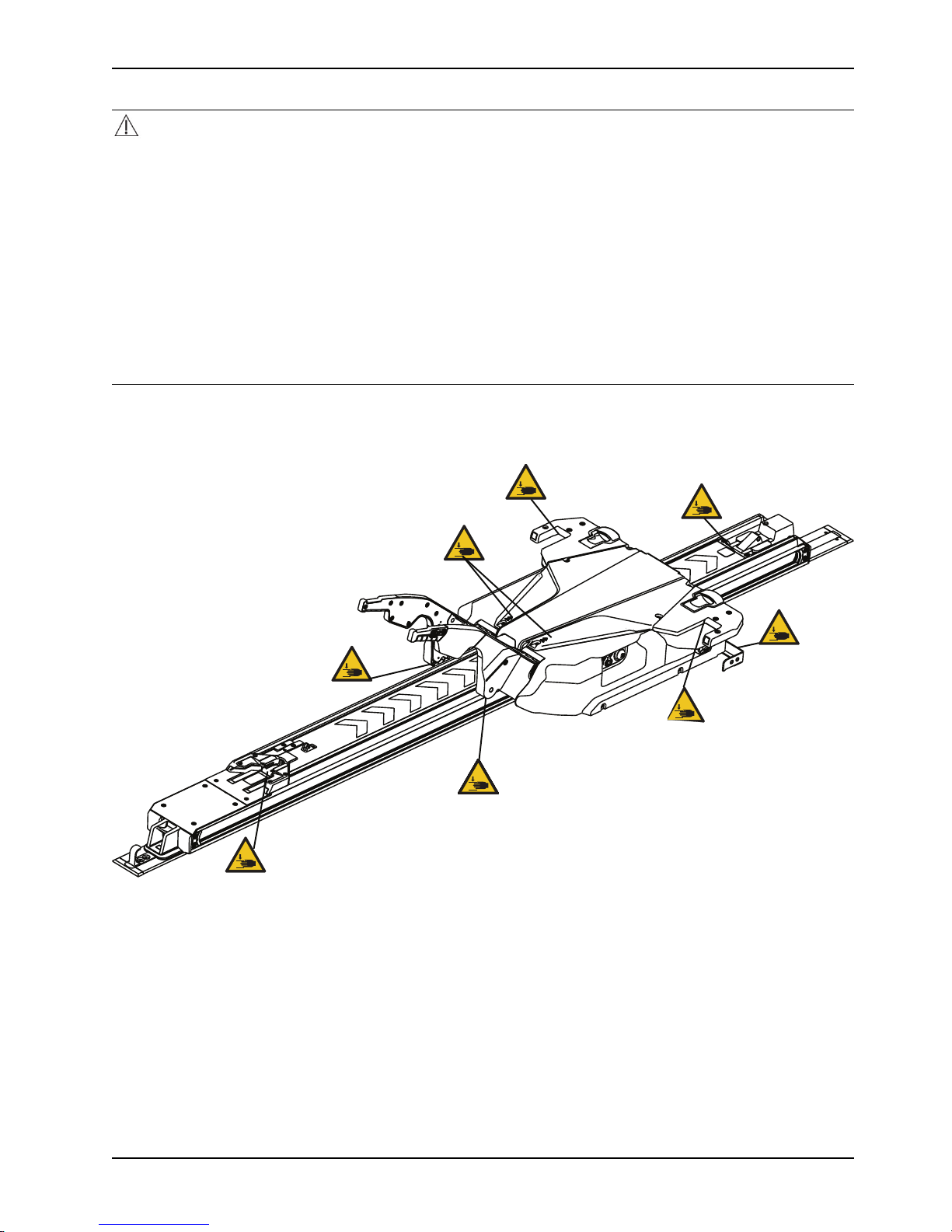
Pinch points
www.stryker.com 6390-009-002 REV D 7
Figure 1: Pinch points

Introduction
This manual assists you with the operation or maintenance of your Stryker product. Read this manual before operating
or maintaining this product. Set methods and procedures to educate and train your staff on the safe operation or
maintenance of this product.
CAUTION
• Improper usage of the product can cause injury to the patient or operator. Operate the product only as described in
this manual.
• Do not modify the product or any components of the product. Modifying the product can cause unpredictable
operation resulting in injury to patient or operator. Modifying the product also voids its warranty.
Notes
• This manual is a permanent part of the product and should remain with the product even if the product is sold.
• Stryker continually seeks advancements in product design and quality. This manual contains the most current
product information available at the time of printing. There may be minor discrepancies between your product and
this manual. If you have any questions, contact Stryker Customer Service or Technical Support at 1-800-327-0770.
Product description
The Stryker Model 6390 Power-LOAD® power-loading cot fastener system is designed to lift, lower, or steer compatible
ambulance cots into and out of an emergency ground transport vehicle. When the cot is securely attached to the system,
a battery powered hydraulic system assists the operators in loading and unloading a cot. The system also secures the
compatible ambulance cot within the vehicle for patient transportation purposes. When the cot is secured in the
transport position, Power-LOAD inductively charges compatible model 6506 Power-PRO™ XT and 6516 Power-PRO™
IT ambulance cots. In the event of power loss, the system remains functional for securing the cot within the vehicle.
Indications for use
Power-LOAD is intended to assist with loading and unloading of a compatible wheeled stretcher (ambulance cot) to and
from a transport vehicle and to secure the ambulance cot during transport. The device has a maximum safe working
load of 870 lb (395 kg), which includes the weight of the ambulance cot, patient, and equipment attached to the cot
(such as oxygen bottles, monitors, and pumps). The intended users of the device are trained professionals, including
emergency medical service and medical care center personnel, as well as medical first responders, service technicians
and installers.
Expected service life
Power-LOAD has a seven year expected service life under normal use conditions and with appropriate periodic
maintenance.
Contraindications
None known.
8 6390-009-002 REV D www.stryker.com

Specifications
Safe working load
Note: Safe working load represents the sum of the
cot total weight and patient
Introduction
870 lb
395 kg
Maximum lift capacity (patient and accessories)
Overall length
Minimum length 89.5 in. 228 cm
Width 24.5 in. 62 cm
Weight
Floor plate assembly 16.5 lb 7.5 kg
Anchor assembly 23 lb 10.5 kg
Transfer assembly
Trolley assembly 105 lb 48 kg
Minimum operators required for loading/unloading an
occupied cot
Minimum operators required for loading/unloading an
unoccupied cot
Recommended loading height 22 in. to 36 in. 56 cm to 91 cm
Hydraulic oil
Electrical requirements
Battery duty cycle, charging 100%
700 lb 318 kg
95 in. 241 cm
67 lb 30.5 kg
2
1
Mobil Mercon® V Blend ATF Oil (6500-001-293)
See the Mobil Mercon V Blend ATF oil material
safety data sheet (MSDS) for safety information.
12.8 VDC-15.6 VDC, 15A fuse/breaker, 2 conductor
10 AWG cable
Battery duty cycle, loading
Battery
Fuse
Standards ANSI/AAMI ES60601-1:2012, CAN/CSA-C22.2 No.
Stryker reserves the right to change specifications without notice.
The yellow and black color scheme is a proprietary trademark of Stryker Corporation.
Hereby, Stryker declares that the radio equipment type short range device is in compliance with Directive 2014/53/EU.
The full text of the EU declaration of conformity is available at the following internet address: http://techweb.med.
strykercorp.com/EMS/EU%20Declaration%20of%20Conformity/index.html.
Labels may be unreadable from a viewing distance greater than 12 inches.
www.stryker.com 6390-009-002 REV D 9
10% (33 sec on/5 min off)
12 VDC, 5 Ah lead acid battery (6390-001-468)
LITTELFUSE 0496060.ZXD-UL
60601-1:14, KKK-A-1822F, IEC 60601-1-12:2014
For standards that require specific options, see
Standards with required options on page 11.
Introduction
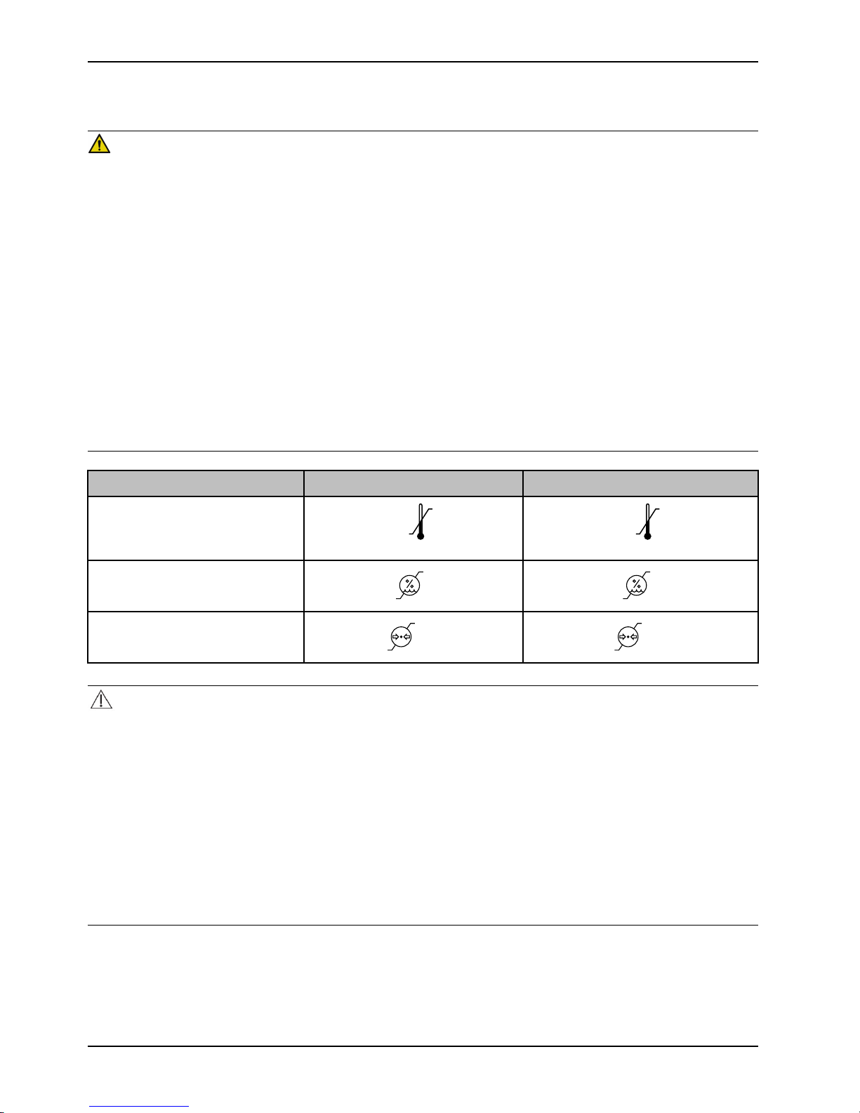
130 °F
(54 °C)
-30 °F
(-34 °C)
158 °F
(70 °C)
-30 °F
(-34 °C)
93%0%93%
0%
1060 hPa
700
1060 hPa
700
Specifications (Continued)
WARNING
• Do not operate Power-LOAD with a voltage that is inconsistent with the rating on the product.
• Do not operate Power-LOAD above its duty cycle to avoid the risk of equipment damage or smoke hazard.
• Do not connect Power-LOAD to a 24 VDC vehicle circuit. Always connect Power-LOAD to a 12.8 VDC-15.6 VDC
vehicle circuit that is on a 15A fuse/breaker to prevent power hazards.
• Power-LOAD operates at 13.56 MHz when you use Power-LOAD controls with a powered cot (Power-PRO XT or
Power-PRO IT) that could interfere with other equipment that operate at this frequency band.
• The use of accessories, transducers, and cables, other than those specified, with the exception of transducers and
cables that are sold by Stryker as replacement parts for internal components, may result in increased emissions or
decreased immunity of the Power-LOAD system.
• Do not use the Power-LOAD system and the Power-PRO cot adjacent to or stacked with other equipment. If
adjacent or stacked use is necessary, observe the Power-LOAD system to confirm normal operation in the
configuration where it will be used.
• Power-LOAD operates primarily at these frequencies: 70 - 85 kHz for inductive charging and 13.56 MHz±7 kHz,
Amplitude Modulated (OOK), ERP: -82.37 dBm. The inductive charging can operate between these frequencies: 70 125 kHz. Other equipment may interfere with the Power-LOAD system, even if that other equipment complies with
CISPR emission requirements.
Environmental conditions
Operation Storage and transportation
Temperature
Relative humidity
Atmospheric pressure
CAUTION
• This equipment has been tested and found to comply with the limits for a Class A digital device, pursuant to part 15
of the FCC Rules. These limits are designed to provide reasonable protection against harmful interference when the
equipment is operated in a commercial environment. This equipment generates, uses, and can radiate radio
frequency energy and, if not installed and used in accordance with the instruction manual, may cause harmful
interference to radio communications. Operation of this equipment in a residential area is likely to cause harmful
interference in which case the user will be required to correct the interference at their expense. In the event of
interference, please relocate or reorient the Power-LOAD system or interfering product.
• Always relocate or reorient the Power- LOAD system or interfering product in the event of interference. This device
complies with Part 18 of the FCC Rules.
• Do not use portable RF communications equipment (including peripherals such as antenna cables and external
antennas) no closer than 30 cm (12 in.) to any part of the Power-LOAD system, including cables specified by the
manufacturer. Otherwise, degradation of the performance of this equipment may result.
10 6390-009-002 REV D www.stryker.com

Introduction
Specifications (Continued)
CAUTION (CONTINUED)
• The emissions characteristics of this equipment make it suitable for use in industrial areas and hospitals (CISPR 11
class A). This equipment generates, uses, and can radiate radio frequency energy and, if not installed and used in
accordance with the instruction manual, may cause harmful interference to radio communications. Operation of this
equipment in a residential area (for which CISPR 11 class B is normally required) is likely to cause harmful
interference, in which case the user will be required to correct the interference at their expense. In the event of
interference, please relocate or reorient the Power-LOAD system or interfering product.
Notes
• This device is compliant to European Directive 2011/65/EU Restriction of Hazardous Substances (RoHS) as it does
not contain any of the restricted substances in excess of the acceptable threshold in electrical and electronic
equipment.
• This device is considered an "article" as defined in Article 3(3) of the European Registration, Evaluation,
Authorization, and restriction of Chemicals (REACH) Regulation (EC) 1907/2006, and it does not release
substances under its normal use. Suppliers of articles are not required to register with the European Chemicals
Agency (ECHA), but must provide recipients with information on Substances of Very High Concern (SVHC) if those
are present above a concentration limit of 0.1 % weight on an article level. Based on a diligent review of information
provided by our suppliers, this device does not contain above 0.1 % weight (w/w) threshold of any (SVHC) as listed
by the ECHA as of the 30MAR2010 release. Stryker will continue to monitor REACH regulations for any SVHC that
may be included in subsequent ECHA candidate lists and will communicate this information to customers.
Standards with required options
To be compliant with the standards, you must use Power-LOAD with the following compatible cots. See the Operations
Manual for your cot model for more information.
Note: Compatible cot is loaded into Power-LOAD in powered mode for crash testing.
Standard Power-LOAD compatible cot models
SAE J3027 and AS/NZS-4535:1999
BS EN 1789:2007
6500, 6506
6500, 6506, 6085, 6086
www.stryker.com 6390-009-002 REV D 11
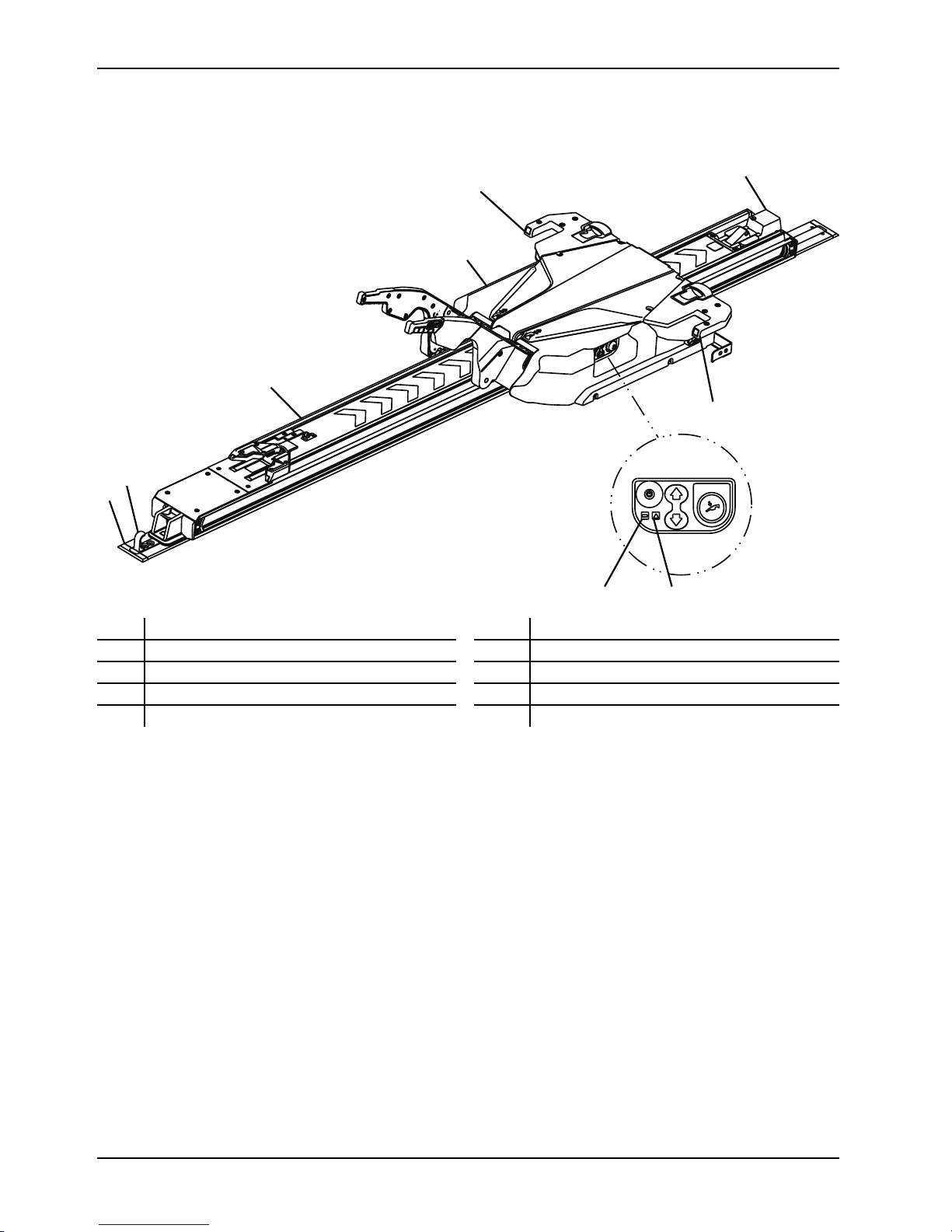
Product illustration
A
B
C
D
E
F
G
H
I
J
H
Introduction
A Foot end F
B
C
D
E
Floor plate
Safety hook
Transfer assembly
Trolley assembly
G Head end
H
I
J Error LED
Anchor assembly
LED indicator, head end
Battery LED
Important contact information
For information about Federal Ambulance Specification KKK-A-1822F, contact:
Chief, Automotive & Commodity Management Branch (QMDAA)
Office of Motor Vehicle Management
General Services Administration
R2200 Crystal Drive, Suite 1006
Arlington, VA 22202 USA
Telephone: 703-605-2277
For more information about AMD standards, contact:
Ambulance Manufacturers Division
(National Truck Equipment Association)
37400 Hills Tech Drive
Farmington Hills, MI 48331-3414 USA
12 6390-009-002 REV D www.stryker.com
Introduction
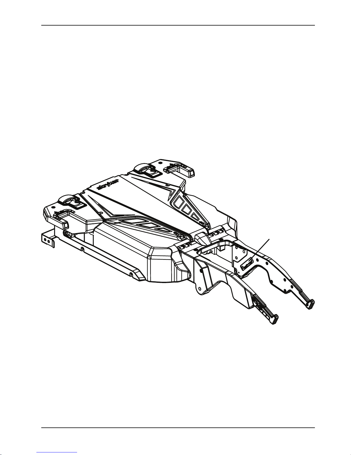
A
Contact information
Contact Stryker Customer Service or Technical Support at: 1-800-327-0770.
Stryker Medical
3800 E. Centre Avenue
Portage, MI 49002
USA
To view your operations or maintenance manual online, see https://techweb.stryker.com/.
Have the serial number (A) of your Stryker product available when calling Stryker Customer Service or Technical
Support. Include the serial number in all written communication.
Serial number location
Date of manufacture
The year of manufacture is the first 2 digits of the serial number.
www.stryker.com 6390-009-002 REV D 13

Cleaning
WARNING
• Always press the main power button to turn the unit off before service or cleaning.
• Always use any appropriate personal protective equipment while power washing to avoid inhaling contagion. Power
washing equipment may aerate contamination.
CAUTION
• Do not spray directly underneath the trolley up in to the trolley mechanism. Water could gain ingress into the trolley
housing and may accelerate corrosion or degrade operation.
• Do not clean, service, or perform maintenance while the product is in use.
The product is power washable. The product may show some signs of oxidation or discoloration from continuous
washing. No degradation of the product’s performance will occur from power washing as long as you follow the proper
procedures.
• Follow the cleaning solution manufacturer’s dilution recommendations exactly.
• Power wash Power-LOAD with recommended cleaners. Hose down the product and towel dry the transfer rails and
arm hinges.
• Power wash Power-LOAD with a hand held wand unit or wipe the product with a clean cloth and recommended
cleaners.
• When you hose down or power wash the product, do not spray directly underneath the trolley up in to the trolley
mechanism. Water could gain ingress into the trolley housing and may accelerate corrosion or degrade operation.
• Using a soft cloth and brush, clean the transfer roller channels to prevent debris accumulation.
• Remove the trolley top cover and patient left side cover assembly to towel dry the control board assembly.
• Disconnect the motor and battery connectors and towel dry the connectors.
• Towel dry the transfer rails and arm hinges.
• When cleaning, park the ambulance uphill and extend the transfer and trolley so the water drains out of the rear
end of the vehicle patient compartment.
Note: Water that gets into the Power-LOAD system will drain through the drain tube to the underside of the vehicle.
Suggested cleaners
In general, when used in concentrations recommended by the manufacturer, either phenolic type or quaternary
(excluding Virex® TB) type disinfectants can be used. Iodophor type disinfectants are not recommended for use
because staining may occur.
WARNING
Always wipe the product with clean water and dry after cleaning. Some cleaning products are corrosive in nature and
may cause damage to the product. Failure to properly rinse and dry the product leaves a corrosive residue on the
surface of the product and may cause premature corrosion of critical components.
Suggested cleaners include:
• Quaternary cleaners (active ingredient - ammonium chloride)
• Phenolic cleaners (active ingredient - o-phenylphenol)
• Chlorinated bleach solution (5.25% - less than 1 part bleach to 100 parts water)
Avoid over saturation. Do not allow the product to stay wet longer than the chemical manufacturer's guidelines for
proper disinfecting.
Note: Failure to follow the above directions when using these types of cleaners may void this product’s warranty.
14 6390-009-002 REV D www.stryker.com

Preventive maintenance
Regular inspection and adjustments
Maintenance intervals
This schedule is a general guide to maintenance. The required maintenance schedule may vary based on:
• Call volume
• Weather
• Terrain
• Geographical location
• Individual usage
If you are not sure how or when to perform these checks, contact your Stryker Service Technician.
When you perform Power-LOAD preventive maintenance checks, you must perform a preventive maintenance check on
its corresponding Power-LOAD compatible cot and the optional wheel guide assembly (if applicable) to confirm
operability of the entire system.
Power-LOAD compatible cot maintenance
Wear items that may require replacement on the Power-LOAD compatible cot include the cot arm spacer (6500-002-
123), base dead stop (6085-001-094), and load wheel pin (6500-002-104).
Optional wheel guide assembly maintenance (if applicable)
To preserve Power-LOAD fastener functionality, make sure that the wheel guide is functional and its structure has not
been compromised. The wheel guide rail system assists the Power-LOAD system in loading the cot. If the wheel guide
has been compromised, replace it immediately.
Note: The Power-LOAD maintenance schedule is based on 10 calls per day. Adjust the routine maintenance schedule
to your actual service usage.
Every month
Check
Lock location
Routine
Clean debris from the foot end lock location on the
transfer
Every three months
Check
Loose fasteners Replace if loose
Battery terminal screws Tighten loose screws (torque to 9 in-lb)
Transfer assembly and anchor assembly Clean debris from the top of the transfer assembly and
Routine
anchor assembly
Transfer roller channels Clean transfer roller channels to prevent debris
Trolley stop ramp Tighten loose screws
www.stryker.com 6390-009-002 REV D 15
accumulation

Every twelve months
Preventive maintenance
Check
Battery
All parts
Dead stop bumpers
Motor Replace when no motor motion exists
Cylinder rod end Replace if Power-LOAD functions in manual mode and
Full functionality See Installation checklist on page 16
Hydraulic
Transfer lock bearing
V-guide rollers
Routine
Replace if lifting is sluggish
Check and replace any worn parts, including arm covers,
arm wear pads, trolley top and side covers, cot release
handle springs, anchor lever cover, transfer lock plate,
transfer lock pin, or cot guides, if necessary
Replace if the corner is damaged
the error LED is illuminated
Check for hydraulic leaks
Replace once per year
Note: During bearing replacement, make sure that the
surrounding area is clean (anchor) and apply
molybdenum disulfide grease to the transfer lock pin.
If the product is difficult to roll or wear is noticeable in the
transfer roller channel beyond the inner rod, replace the
V-guide rollers on the trolley and switch the patient right,
outside, bottom transfer rod with the patient right, outside
top transfer rod. Check all remaining rollers for damage
or excessive wear. Replace, if necessary.
Lift arm springs Replace the lift arm springs (0038-895-000) that are
located under the trolley top cover
Installation checklist
CAUTION
The manual overrides allow the Power-LOAD system to move freely.
Note: Allow the battery to charge for a minimum of 20 minutes before you start the Power-LOAD functional check. The
battery will only charge when the trolley is locked at the head end of the vehicle patient compartment. The battery power
LED should flash green while charging.
Before you start the Power-LOAD functional check, make sure that the:
• Check is performed with a Power-LOAD compatible Power-PRO cot (Model 6500, 6506, 6510, 6516)
• Power-LOAD is locked at the foot end of the vehicle patient compartment with the lifting arms down
• Power is turned on
• LEDs on the trolley assembly wings flash amber
16 6390-009-002 REV D www.stryker.com

Preventive maintenance
Installation checklist (Continued)
Notes
• When you press the main power button, the battery power LED also illuminates to indicate that the Power-LOAD
system is on. If the trolley battery is low, a flashing amber error LED may appear.
• Check both the upper and lower cot control switches when you check the cot button functionality.
Lift the vehicle bumper to the raised position, if equipped.
Lock the Power-LOAD compatible cot into Power-LOAD.
Check that both cot load wheel pins are locked into Power-LOAD (latches).
Check that LEDs change from flashing amber to solid green.
Press and hold the retract (-) button on the cot control switch to fully retract the cot undercarriage.
Push the cot into the vehicle patient compartment until it locks at the head end of the vehicle patient
compartment. Make sure that the lifting arms lower until the cot wheels are on the vehicle patient compartment
floor and the cot foot end locks into the cot fastener.
Make sure that the cot is locked into Power-LOAD by firmly pulling side to side on the foot end of the cot.
Press and hold the extend (+) button on the cot control switch to make sure that the cot does not extend in the
vehicle patient compartment. The cot legs should not attempt to lift in the transport position.
Note: Press the retract (-) button on the cot control switch to allow motion in some conditions.
Press and hold the release lever at the foot end of the Power-LOAD system and pull to remove the cot from the
vehicle patient compartment. Make sure that the lifting arms raise the cot until the cot wheels are off the vehicle
patient compartment floor.
Make sure that the head end LED indicators are solid green. Press and hold the extend (+) button on the cot
control switch to extend the cot until the cot wheels rest on the ground and the cot is no longer supported by the
Power-LOAD lifting arms.
Note: The lifting arms should remain in the full down position after the cot is released from Power-LOAD.
Press the up (↑) button on the Power-LOAD control panel to raise the lifting arms and the cot to the highest
position.
Note: The cot legs do not retract.
Press the down (↓) button on the Power-LOAD control panel to lower the lifting arms and the cot.
Press the release button on the cot control switch to release the cot from Power-LOAD. The head end LED
indicators will flash amber.
Lock the cot into Power-LOAD again.
Press the up (↑) button on the Power-LOAD control panel to lift the cot up to the highest position.
Note: The cot legs do not retract.
Press the manual release button on the Power-LOAD control panel to lower the cot. Continue to hold the button
until the lifting arms are clear of the cot.
Lift one of the two manual cot release handles at the head end of the trolley to unlock the cot.
Roll the cot away from Power-LOAD.
Raise the lifting arms and push the trolley into the vehicle patient compartment to the transport position. With the
trolley at the head end, allow the arms to lower.
Make sure that the battery power LED is flashing green when the trolley is in the transport position.
Load the Power-LOAD compatible cot without using the load functions to simulate manual loading of the cot into
the vehicle patient compartment. Make sure that the cot locks into place.
Press and hold the release lever at the foot end of the Power-LOAD system and pull to remove the cot from the
vehicle patient compartment. Make sure that the cot safety bar is connected with the vehicle.
Note: Only the cot will unlock. The trolley should remain at the head end of Power-LOAD.
To unlock the trolley, raise the lifting arms and press the trolley release button at the head end of the Power-
LOAD system. Slide the trolley only a few inches toward the foot end.
www.stryker.com 6390-009-002 REV D 17

Preventive maintenance
Installation checklist (Continued)
Slide the manual lock override closest to the foot end on the transfer and push the transfer out toward the foot
end. Make sure that the transfer can be unlocked.
Fully extend Power-LOAD out of the vehicle patient compartment.
Slide the manual lock override closest to the head end on the transfer and push the transfer in toward the head
end. Make sure that the transfer can be unlocked.
Visually inspect the head end transfer bumpers to make sure that they are installed flush to the outer edge of
the transfer assembly with no signs of misalignment or improper installation.
Visually check that all bolts and screws are tight, with no signs of protruding or missing fasteners.
Push on the head end pawl and use the foot end release lever to activate the head end pin to make sure that
they move freely and do not bind after you let go.
For Type II ambulances or if the cot center line is 17.5 in. (44.5 cm) or less from the vehicle wall, make sure that
the optional wheel guide assembly (6390-027-000) is installed. Mark N/A if the wheel guide is not required.
Press the main power button to turn the product off. You may need to turn the product on and then off to make
sure that Power-LOAD is off and not in sleep mode.
Note: If you will not use Power-LOAD for a week or more, press the main power button to turn the product off and avoid
draining the battery. You may need to turn the product on and then off to make sure that Power-LOAD is off and not in
sleep mode.
Product serial number:
Installed by: Date:
Inspected by: Date:
Note: Maintain a copy of this record for at least seven years.
Flat roller and V-guide part replacement schedule
You must replace the flat roller and V-guide parts every 14,110 calls. This is to make sure that the Power-LOAD
remains functional. Follow this call volume time table to remain compliant with this requirement. The time table will also
help plan appropriate service intervals.
Calls per day
6 80
7-8 60
9-10 48
11-12 40
13 36
14-15
Months
30
Transfer lock bearing part replacement schedule
You must replace the transfer lock bearing parts every 3,653 calls. This is to make sure that Power-LOAD remains
functional. Follow this call volume time table to remain compliant with this requirement.
18 6390-009-002 REV D www.stryker.com

Preventive maintenance
Transfer lock bearing part replacement schedule (Continued)
Calls per day
2 60
3 40
4-5
6 20
7-8
9-10 12
11-12 10
13-15 8
Months
24
15
www.stryker.com 6390-009-002 REV D 19

Maintenance record
Preventive maintenance
Date Maintenance operation
performed
By Hours
20 6390-009-002 REV D www.stryker.com

Preventive maintenance
Training record
Training date
Trainee name Basic training Refresher update Owner’s manual, in-
service, formal class, etc.
www.stryker.com 6390-009-002 REV D 21

Quick reference replacement parts
These parts are currently available for purchase. Call Stryker Customer Service: 1-800-327-0770 for availability and
pricing.
Name Number
Actuator assembly, trolley 6390-001-028
Battery 6390-001-468
Board, comm, trolley 6390-001-378
Board, inductive primary, anchor 6390-001-147
Board assembly, trolley control 6390-101-014
Bronze bearing (anchor lock bearing) 0081-439-000
Bumper block, mid position 6390-001-322
Coil assembly, middle, anchor
Coil assembly, primary, anchor
Coil assembly, trolley
Cot release handle spring
Cover, top
Cover assembly, side, patient right
Cover assembly, side, patient left
Cover assembly, wing, patient right
Cover assembly, wing, patient left
Cover, arm, mid, patient right
Cover, arm, mid, patient left
Cover, arm, head end, patient right
Cover, arm, head end, patient left
Grip, arm, patient left
Grip, arm, patient right
Dead stop block, threaded 6390-001-246
6390-001-030
6390-001-071
6390-001-066
0038-376-000
6390-101-420
6390-001-041
6390-001-042
6390-101-047
6390-101-048
6390-001-369
6390-001-370
6390-001-371
6390-001-372
6390-001-341
6390-001-368
Dead stop block, thru hole 6390-001-244
Dead stop bumper 6390-001-243
Hydraulics assembly 6390-001-039
Hydraulic fluid
Hydraulic cylinder rod end 6390-001-040
Label, powered operations instructions 6390-101-498
Label, manual operations instructions 6390-001-499
Motor 6390-101-132
Power-LOAD mass casualty fastener, wall mounted fastener (Model 6391)
22 6390-009-002 REV D www.stryker.com
6500-001-293
6391-000-000

Quick reference replacement parts
Name Number
Power-LOAD mass casualty fastener, floor mounted fastener (Model 6391)
Release lever housing 6390-001-105
6391-000-000
Roller assembly, flat
Roller assembly, V-guide 6390-001-025
Sensor, angle position (APS)
Sensor, trolley position (TPS)
Switch, master on/off
Wheel guide rail bumper 6390-001-175
Wheel guide rail 6390-001-176
6390-001-027
6390-001-397
6390-001-361
6390-001-450
www.stryker.com 6390-009-002 REV D 23

Troubleshooting
Transfer/cot does not move out of the transport position
Transfer/cot does not move out of the transport position when you press the release lever at the foot end of the anchor.
If the lifting arms are over the base tube (powered mode)
1. Press the patient right transfer release lever and the trolley release button at the head end of the anchor at the
same time with the help of another person.
2. If the cot is free, then inspect the head end anchor mechanism.
3. If the cot still will not move, then repeat step 1 while simultaneously pulling on the patient right transfer lock trigger
at the foot end of the transfer.
Note: This should allow the cot to be pulled out while it is still locked into the trolley and transfer.
4. With the cot pulled out, look at the underside of the transfer. About 15 in. from the foot end, you will see the metal
hook with a semi-circle cutout at its head end.
a. Push up on the semi-circle and the cot should be free to move.
b. With assistance from another person, pull the cot out.
5. With the cot free, check the foot end anchor mechanism.
a. Remove the transfer to inspect the foot end anchor pin.
b. Remove the anchor mechanism from the foot end anchor.
If the lifting arms are under the base tube
1. With the help of another person, press the transfer release lever and lift up on one of the cot release handles on
the trolley at the same time.
2. If the cot is free, remove the cot and determine whether the black pin will extend up from the anchor head end
cover.
Note: The trolley must be in the mid position and the release lever pressed to elevate the pin.
a. If the pin extends out without signs of damage, check the casting in the trolley release handle mechanism
(6390-001-328) or the plastic lever in the trolley middle mechanism.
b. If the pin does not extend out, check the head end anchor mechanism for damage.
If the cot still will not move
1. Insert a screwdriver into each notch at the head end of the trolley side covers to release the cot head section
latches.
2. After the latches are unlocked, use the release lever at the foot end to release the cot.
3. After the cot is removed, inspect the release handle mechanism in the trolley.
Trolley does not roll smoothly
If rolling is difficult while the trolley is rolling on the transfer
1. Check the rods in the channels on the outside of the transfer extrusion for debris or foreign material and remove, if
necessary.
2. If rolling is still difficult, check to see if the transfer extrusion is worn around the channels. If so, replace the V-guide
rollers on the trolley.
If rolling is difficult while the transfer is rolling on the anchor
1. Check the metal dead stops (6390-001-246) at the head end of the transfer to make sure that they are fully seated
and that they are not rubbing on the anchor extrusion.
2. Check the rods in the channels on the inside of the transfer extrusion. Remove any debris or foreign material.
24 6390-009-002 REV D www.stryker.com
 Loading...