

Stryker 6253 Operation & Maintenance Manual
Evacuation Chair
Chaise d’évacuation/Evakuierungsstuhl
Evacuatiestoel/Sedia per evacuazione
Silla de evacuación/Cadeira de evacuação
Evakueringsstol/Evakuointituoli
Αμαξίδιο εκκένωσης/Krzesło do ewakuacji
Model/Modèle/Modell/Modello/Modelo/Malli/Μοντέλο 6253
Operations/Maintenance Manual
Manuel d’utilisation et d’entretien
Bedienungs- und Wartungshandbuch
Gebruiks-/onderhoudshandleiding
Manuale d’uso e manutenzione
Manual de uso y mantenimiento
Manual de funcionamento/manutenção
Betjenings-/vedligeholdelsesmanual
Användar-/underhållshandbok
Käyttö- ja huolto-ohjekirja
Εγχειρίδιο λειτουργίας/συντήρησης
Instrukcja obsługi/konserwacji
2011/03 6253-001-166 REV C.2 www.stryker.com


International Addresses
FINLAND
Stryker AB, Finland
PO 80 Makelankatu 2
EUROPE HEADQUARTERS
Stryker SA
Cite-Centre, Grand-Rue 90
P.O. Box 1568
1820 Montreux, Switzerland
Phone: 011-41-21-966-12-01
Fax: 011-41-21-966-12-00
EASTERN EUROPE
Stryker SA - Export Business
Grand-Rue 90
P.O. Box 1567
1820 Montreux, Switzerland
Phone: 011-41-21-966-14-00
Fax: 011-41-21-966-14-01
AUSTRIA
Stryker-Howmedica Osterreich GmbH
Millenium Tower
Handelskai 94-96
120 Wien
Austria
Phone: 011-43-1-240 -27-6400
Fax: 011-43-1-240-27-6410
BELGIUM
NV Stryker SA
Ikaros Business Park- Fase III
Ikaroslaan 12
1930 Zaventem, Brussels
Belgium
Phone: 011-32-2-717-9210
Fax: 011-32-2-717-9249
DENMARK
Stryker Denmark
Filial of Stryker AB
Postbox 772
1532 Copenhagen
Denmark
Phone: 011-45-33-93-6099
Fax: 011-45-33-93-2069
ENGLAND
Stryker UK Limited
Stryker House
Hambridge Road
Newbury, Berkshire
RG14 5EG, England
Phone: 011-44-1635-556-500
Phone: 011-44-1635-262-400
Fax: 011-44-1635-580-300
00501 Helsinki
Finland
Phone: 011-35-89-774-4680
Fax: 011-35-89-774-46820
FRANCE
Stryker France SA
ZAC - Avenue de Satolas Green
69330 Pusignan
France
Phone: 011-33-472-45-36-00
Fax: 011-33-472-45-36-99
GERMANY
Stryker Howmedica GmbH
Dr. Homer Stryker Platz 1
47228 Duisburg
Germany
Phone: 011-49-2065-837-0
Fax: 011-49-2065-837-837
GREECE
Stryker Hellas EPE
455 Messogion ave
153 43 Agia Paraskevi
Athens, Greece
Phone: 011-30-2-10-600-32-22
Fax: 011-30-2-10-600-48-12
ITALY
Stryker Italia SrL
Via Ghisalba 15B
00188 Roma
Italy
Phone: 011-39-06-33-05-41
Fax: 011-39-06-33-614-067
MIDDLE EAST / NORTH AFRICA
Stryker Osteonics SA
Twin Towers
11th Floor, Suite 1101 & 1102
P.O. Box 41446
Baniyas Road
Dubai, Deira, UAE
Phone: 011-97-14-222-2842
Fax: 011-97-14-224-7381
NEDERLANDS
Stryker Nederlands BV
(P.O. Box 13, 4180 BA Waardenburg)
4181 CD Waardenburg
The Nederlands
Phone: 011-31-418-569-700
Fax: 011-31-418-569-777
NORWAY
Stryker Norway
Norsk Fillial
Nedre Vollgate 3
0158 Oslo
Norway
Phone: 011-47-22-42-22-44
Fax: 011-47-22-42-22-54
POLAND
Stryker Polska Sp. ZO.O
Kolejowa 5/7
01-217 Warsawa
Poland
Phone: 011-48-22-434-88-50
Fax: 011-48-22-434-88-60
PORTUGAL
Stryker Portugal Produtos
Medicos, LTDA.
Avenida Marechal Gomes
da Costa, 35
1800-255 Lisboa
Portugal
Phone: 011-35 -1-21-839-49-10
Fax: 011-35-1-21-839-49-19
ROMANIA
Stryker Osteonics Romania S.R.L.
19, Leonida Str.
District 2
7000 Bucharest
Romania
Ph one: 011-40-2-12-12-11-22
Fa x: 011- 4 0 -2-12-12-11-3 3
SOUTH AFRICA
Stryker Osteonis PTY. LTD.
3 Susan Street
Strydom Park
Johannesburg, 2194 - South Africa
Mailing Address:
P.O. Box 48039
2129 Roosevelt Park
Johannesburg, South Africa
Phone: 011-27-11-791-4644
Fax: 011-27-11-791-4696
SPAIN
Stryker Howmedica Iberica S.L.U.
Manual Tovar, 35
28034 Madrid
Spain
Phone: 011-34-91-728-35-00
Phone: 011-34-91-358-20-44
Fax: 011-34-91-358-07-48
SWEDEN
Stryker AB/Scandinavia
Box 50425
SE-204 14 Malmo
Sweden
Phone: 011-46-40-691-81-00
Fax: 011-46-40-691-81-91


Table of Contents
Symbols and Definitions ...................................................................1-4
Symbols ...........................................................................1- 4
Warning / Caution / Note Definition........................................................1-4
Introduction ............................................................................1-5
Specifications .......................................................................1-5
Component Identification ...............................................................1-6
Warranty ..............................................................................1-7
Stryker EMS Return Policy ..............................................................1- 8
Return Authorization...................................................................1-8
Damaged Merchandise ................................................................1-8
International Warranty Clause............................................................1- 8
Patent Information ....................................................................1-8
Summary of Safety Precautions .............................................................1-9
Setup Procedures.......................................................................1-10
Operation Guide........................................................................1-1 1
Operating Guidelines ................................................................1-11
Unfolding the Chair ..................................................................1-12
Folding the Chair ....................................................................1-12
Transferring the Passenger to the Stryker Evacuation Chair ....................................1-13
Using Restraint Straps ................................................................1-14
Proper Lifting Techniques..............................................................1-17
Transporting the Passenger on Flat Surfaces . . . . . . . . . . . . . . . . . . . . . . . . . . . . . . . . . . . . . . . . . . . . . . . 1-18
Transporting the Passenger Down Stairs ..................................................1-19
Transporting the Passenger Up Stairs.....................................................1-21
Operating the Wheel Locks ............................................................1-22
Adjusting the Wheel Locking Force.......................................................1-23
Using the Head Support ...............................................................1-2 4
Using Additional Assistance ............................................................1-2 5
Installing the Optional Wall Storage Bracket ................................................1-26
Installing the Optional Cabinet ..........................................................1-27
Installing the Optional Cover............................................................1-28
Removing the Optional Cover...........................................................1-28
Cleaning..............................................................................1-2 9
Washing Procedure ..................................................................1-29
Washing Limitations ..................................................................1-29
Preventative Maintenance.................................................................1-31
Checklist ..........................................................................1-31
Maintenance Record.....................................................................1-3 2
Training Record ........................................................................1-33
Quick Reference Replacement Part List ......................................................1-34
Service Information......................................................................1-3 5
Track Belt Reconditioning .............................................................1-35
Upper Control Handle Cable Replacement .................................................1-37
English
www.stryker.com 6253 -001-166 REV C 1-3
English
Symbols and Definitions
SYMBOLS
Warning/Caution: consult accompanying documentation
Safe Working Load
WARNING / CAUTION / NOTE DEFINITION
The words WARNING, CAUTION and NOTE carry special meanings and should be carefully reviewed.
WARNING
Alerts the reader about a situation, which if not avoided, could result in death or serious injury. It may also describe
potential serious adverse reactions and safety hazards.
CAUTION
Alerts the reader of a potentially hazardous situation, which if not avoided, may result in minor or moderate injury to the
user or passenger or damage to the equipment or other property. This includes special care necessary for the safe and
effective use of the device and the care necessary to avoid damage to a device that may occur as a result of use or
misuse.
NOTE
This provides special information to make maintenance easier or important instructions clearer.
Return To Table of Contents
1-4 6253 -001-166 REV C www.stryker.com
Introduction
INTRODUCTION
This manual is designed to assist you with the operation and maintenance of the Model 6253 Stryker Evacuation Chair.
Read it thoroughly before using the equipment or beginning any maintenance on it.
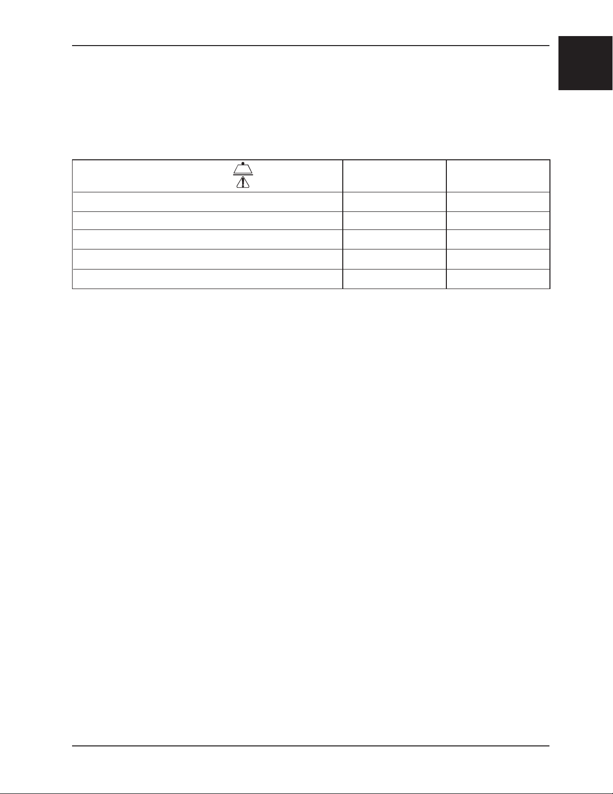
SPECIFICATIONS
English
Maximum Load
1
500 lbs. 228 kg.
Height 45” 114 cm.
Width 20.5” 52 cm.
2
Depth
28” 71 cm.
Folded Depth 11” 28 cm.
Weight 34 lbs. 15.5 kg.
Dimensions are measured from the outermost edges of the main frame. Specifications are rounded. Conversions are calculated
before rounding.
1
Maximum load capacity is total weight distributed in accordance to basic human anatomy. Operators must consider the weight
of the passenger, equipment, and accessories when determining the total load on the product.
2
Depth dimensions are measured with extendable handles retracted.
Stryker reserves the right to change specifications without notice.
Return To Table of Contents
www.stryker.com 6253 -001-166 REV C 1-5
English
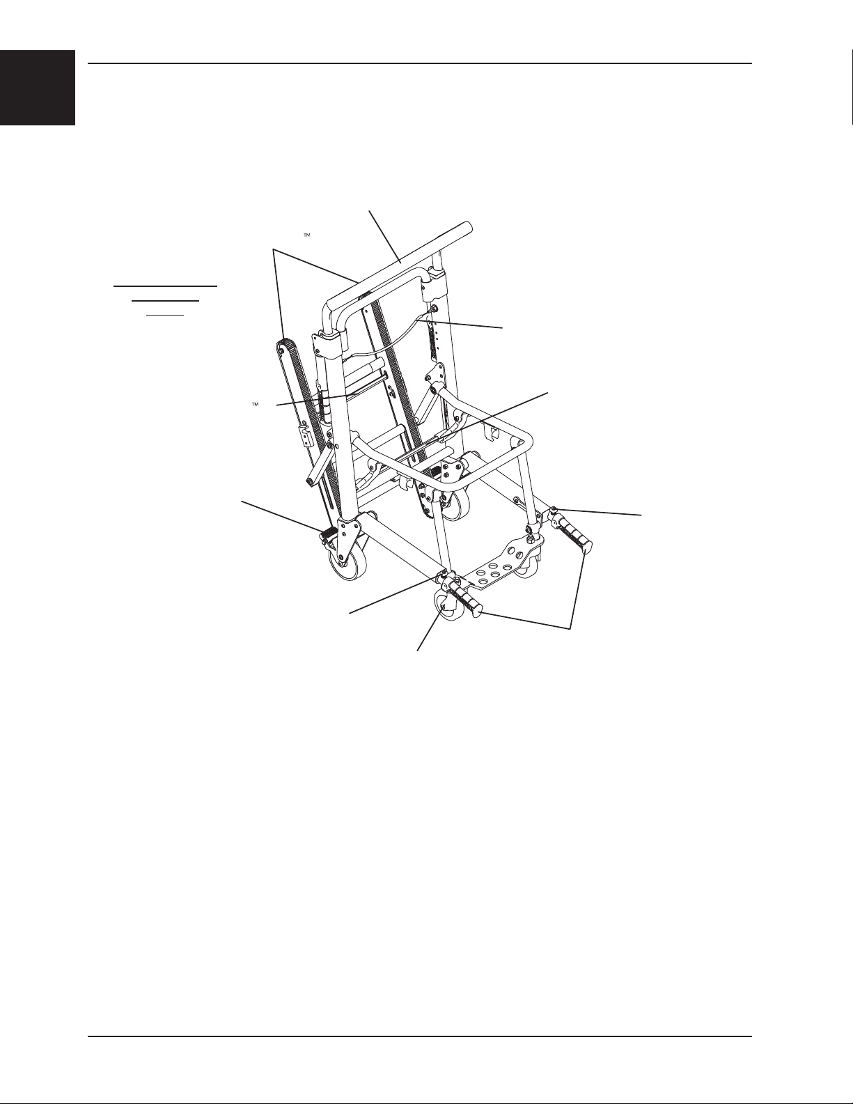
COMPONENT IDENTIFICATION
Stair−TREAD
(Seat components
removed for
clarity)
Stair−TREAD
Lock Bar
Introduction
Upper
Control Handle
Upper Control Handle
Release Cable
Chair Fold
Lock Bar
Wheel Lock
Lift Handle
Release Button
Front Caster
Lift Handle
Release Button
Foot End
Lift Handles
Return To Table of Contents
1-6 6253 -001-166 REV C www.stryker.com
Warranty
Stryker EMS, a division of the Stryker Corporation, offers two distinct warranty options in the
United States:
One (1) year parts and labor. Under this option, Stryker EMS warrants to the original purchaser
that its products should be free from manufacturing non-conformances that affect product
performance and customer satisfaction for a period of one (1) year after date of delivery. Stryker’s
obligation under this warranty is expressly limited to supplying replacement parts and labor for, or
replacing, at its option, any product that is, in the sole discretion of Stryker, found to be defective.
Two (2) year parts. Under this option, Stryker EMS warrants to the original purchaser that nonexpendable components of its products should be free from manufacturing non-conformances
that affect product performance and customer satisfaction for a period of two (2) years after date
of delivery. Stryker’s obligation under this warranty is expressly limited to supplying replacement
parts for, or replacing, at its option, any product which is, in the sole discretion of Stryker, found to
be defective. Expendable components, i.e. mattresses, restraints, I.V. poles, storage nets, storage
pouches, Oxygen straps, and other soft goods, have a one (1) year limited warranty with this option.
Under either warranty option, Stryker EMS products are designed for a 7 year expected service
life under normal use, conditions, and with appropriate periodic maintenance as described
in the maintenance manual for each device. Stryker warrants to the original purchaser
that the welds on its EMS products will be free from structural defects for the expected 7
year life of the EMS product as long as the original purchaser owns the product. Original
purchasers will also obtain a three (3) year limited parts warranty for the X-frame components
of the MX-PRO R3 stretcher provided they also purchase X-frame guards at the time of the
original purchase and the guards are installed on the MX-PRO before it is put into service.
If Stryker requests, products or parts for which an original purchaser makes a warranty
claim, the purchaser shall return the product or part prepaid freight to Stryker’s factory.
Any improper use or alteration or repair by unauthorized service providers in such a manner as
in Stryker’s judgment affects the product materially and adversely, shall void this warranty. Any
repair of Stryker products using parts not provided or authorized by Stryker shall void this warranty.
No employee or representative of Stryker is authorized to change this warranty in any way.
This statement constitutes Stryker EMS’s entire warranty with respect to the aforesaid equipment.
STRYKER MAKES NO OTHER WARRANTY OR REPRESENTATION EITHER EXPRESSED OR
IMPLIED, EXCEPT AS SET FORTH HEREIN. THERE IS NO WARRANTY OF MERCHANTABILITY
AND THERE ARE NO WARRANTIES OF FITNESS FOR ANY PARTICULAR PURPOSE. IN NO
EVENT SHALL STRYKER BE LIABLE HEREUNDER FOR INCIDENTAL OR CONSEQUENTIAL
DAMAGES ARISING FROM OR IN ANY MANNER RELATED TO SALES OR USE OF ANY SUCH
EQUIPMENT.
English
Return To Table of Contents
www.stryker.com 6253 -001-166 REV C 1-7
English
Warranty
STRYKER EMS RETURN POLICY
Cots, Stair Chairs, Stryker Evacuation Chairs, Cot Fasteners and Aftermarket Accessories may be returned up to 180 days of receipt if they meet the following guidelines:
Prior to 30 Days
• 30daymoneybackguaranteeineffect
• StrykerEMSisresponsibleforallcharges
• Returnswillnotbeapprovedonmodifieditems
Prior to 90 Days
• Productmustbeunused, undamaged and in the original packaging
• Customerisresponsiblefora10%restockingfee
Prior to 180 Days
• Productmustbeunused, undamaged and in the original packaging
• Customerisresponsiblefora25%restockingfee
RETURN AUTHORIZATION
Merchandise cannot be returned without approval from the Stryker Customer Service Department. An
authorization number will be provided which must be printed on the returned merchandise. Stryker reserves
the right to charge shipping and restocking fees on returned items.
SPECIAL, MODIFIED, OR DISCONTINUED ITEMS NOT SUBJECT TO RETURN.
DAMAGED MERCHANDISE
ICC Regulations require that claims for damaged merchandise must be made with the carrier within fifteen
(15) days of receipt of merchandise. DO NOT ACCEPT DAMAGED SHIPMENTS UNLESS SUCH DAMAGE
IS NOTED ON THE DELIVERY RECEIPT AT THE TIME OF RECEIPT. Upon prompt notification, Stryker will
file a freight claim with the appropriate carrier for damages incurred. Claim will be limited in amount to the
actual replacement cost. In the event that this information is not received by Stryker within the fifteen (15)
day period following the delivery of the merchandise, or the damage was not noted on the delivery receipt
at the time of receipt, the customer will be responsible for payment of the original invoice in full.
Claims for any short shipment must be made within thirty (30) days of invoice.
INTERNATIONAL WARRANTY CLAUSE
This warranty reflects U.S. domestic policy. Warranty outside the U.S. may vary by country. Please contact
your local Stryker Medical representative for additional information.
PATENT INFORMATION
Stryker products are covered by one or more of the following patents:
United States 5,575,026 6,276,010 6,648,343 6, 908,133 6,796,757
5,537,700 6,125,485 6,735,794 7,10 0 , 224 7,398,571
D527,103
Other Patents Pending
Return To Table of Contents
1-8 6253 -001-166 REV C www.stryker.com
Summary of Safety Precautions
The following is a list of safety precautions that must be observed when operating or servicing this unit. The precautions
are repeated throughout the manual, where applicable. Carefully read this list before using or servicing the unit.
WARNING
• Improper usage of the Stryker Evacuation Chair can cause injury to the passenger or operator. Operate the Stryker
Evacuation Chair only as described in this manual.
• Do not modify the Stryker Evacuation Chair. Modifying the chair can cause unpredictable operation resulting in
injury to the passenger or operator. Modifying the chair will also void its warranty.
• Improper maintenance can cause injury or damage to the unit. Maintain the Stryker Evacuation Chair as described
in this manual. Use only Stryker approved parts and maintenance procedures. Using unapproved parts and
procedures could cause unpredictable operation and/or injury and will void the product warranty.
• Do not allow untrained helpers to assist in the operation of the Stryker Evacuation Chair. Untrained technicians/
helpers can cause injury to the passenger or themselves.
• An unlocked chair can fold during use, causing injury to the passenger or operator. Always make sure the chair is
locked in the unfolded position before use.
• To avoid injury, always verify the lift handles are locked in place before using them to lift the chair.
• Always use all restraint straps to secure the passenger on the chair. An unrestrained passenger may fall from the
chair and be injured.
• Never leave a passenger unattended on the chair or injury could result. Hold the chair securely while a passenger
is on the chair.
• The Stryker Evacuation Chair is not recommended for use with suspected cervical, spinal, or fracture injuries.
• To avoid injury when a passenger weighing more than 200 pounds is on the chair, use a minimum of two operators
to transport on stairs. If more people are required to safely control the chair, see page 1-25 for the proper
positioning of each helper.
• Only use the wheel locks during passenger transfer or without a passenger on the chair. Tipping could occur if
the chair is moved while wheel locks are applied, resulting in injury to the passenger or operator and/or damage
to the chair.
• Never use a wheel lock on a chair with excessively worn wheels. Using a wheel lock on a wheel with less than a
5” diameter could compromise the holding ability of the wheel lock, possibly resulting in injury to the passenger or
operator and/or damage to the chair or other equipment.
• To avoid injury, always verify the Stair-TREAD™ system is securely locked in place before transporting the
passenger.
• Water, ice and debris on the stairs can affect operator footing and proper operation of the Stair-TREAD™ system.
To avoid injury, clear the path or consider an alternate route.
• Condensation, water, ice and/or debris on the Stair-TREAD™ system can cause unpredictable performance,
resulting in a sudden change in the weight the operators must support. To avoid injury, and to aid proper operation
of the Stair-TREAD™ system, ensure the belts are clean and dry before transporting the passenger.
• Never lubricate the Stair-TREAD™ system. Lubrication on the system can cause inconsistent operation possibly
resulting in injury to the passenger or operator.
• To avoid injury to the operators and/or the passenger, operators should never attempt to transport passenger loads
greater than what they can safely lift.
• Do not sand the track teeth. Deformation of the teeth can cause unpredictable chair performance resulting in injury
to the operators and/or passenger.
English
CAUTION
• Casters are not suitable for all surfaces. Caution should be used at all times.
• Wheel locks are only intended to help prevent the empty chair from rolling while unattended and to aid in passenger
transfer. The wheel lock may not provide sufficient resistance on all surfaces or under loads.
• Release the red track release bar before clicking the Stair-TREAD™ system into the locked position. Failure to follow
this procedure could result in the track failing to lock. Always verify the Stair-TREAD™ system is locked by trying
to fold it before descending stairs.
Return To Table of Contents
www.stryker.com 6253 -001-166 REV C 1-9
English
Setup Procedures
Unpack the cartons and check all items for proper operation. It is important that the Stryker Evacuation Chair is
working properly before it is put into service. Have a qualified service person use the following list and the operation
instructions to check the chair before it is put into service.
• All fasteners secure (reference all assembly drawings).
• All welds intact, not cracked or broken.
• No bent or broken tubing or sheet metal.
• No debris in wheels.
• All wheels secure and rolling properly.
• Chair unfolds and locks properly.
• No rips or cracks in seat or backrest.
• Passenger restraints intact and working properly.
• Wheel locks operating properly.
• Foot end lift handles extend and lock properly.
• Head end lift handles fold and unfold.
• Casters secure, rolling and swiveling properly
• Upper control handle extends and locks in both positions
• Stair-TREAD™ system unfolds and locks
• Track belts roll properly
• Optional accessories intact and operating properly.
WARNING
Do not modify the Stryker Evacuation Chair. Modifying the chair can cause unpredictable operation resulting in injury to
the passenger or operator. Modifying the chair will also void its warranty.
Return To Table of Contents
1-10 6253 -001-166 REV C www.stryker.com
Operation Guide
OPERATING GUIDELINES
• Use the Stryker Evacuation Chair only as described in this manual.
• Read all labels and instructions on the chair before using the chair.
• To avoid injury when a passenger weighing more than 200 pounds is on the chair, use a minimum of two operators
to transport on stairs. If more people are required to safely control the chair, see page 1-25 for the proper
positioning of each helper.
• Do not roll the chair, ascend, or descend stairs without advising the passenger. Stay with the passenger and
control the chair at all times.
• Only use the wheel locks during passenger transfer or without a passenger on the chair.
• Always use the restraint straps when a passenger is on the chair.
• Use properly trained helpers when necessary to control the chair and passenger.
WARNING
• Always use all restraint straps to secure the passenger on the chair. An unrestrained passenger may fall from the
chair and be injured.
• Only use the wheel locks during passenger transfer or without a passenger on the chair. Tipping could occur if the
chair is moved while the wheel locks are applied, resulting in injury to the passenger or operator and/or damage
to the chair.
• Condensation, water, ice and/or debris on the Stair-TREAD™ system can cause unpredictable performance,
resulting in a sudden change in the weight the operators must support. To avoid injury, and to aid proper operation
of the Stair-TREAD™ system, ensure the belts are clean and dry before transporting the passenger.
• To avoid injury to the operators and/or the passenger, operators should never attempt to transport passenger loads
greater than what they can safely lift.
English
Return To Table of Contents
www.stryker.com 6253 -001-166 REV C 1 -11
English
Operation Guide
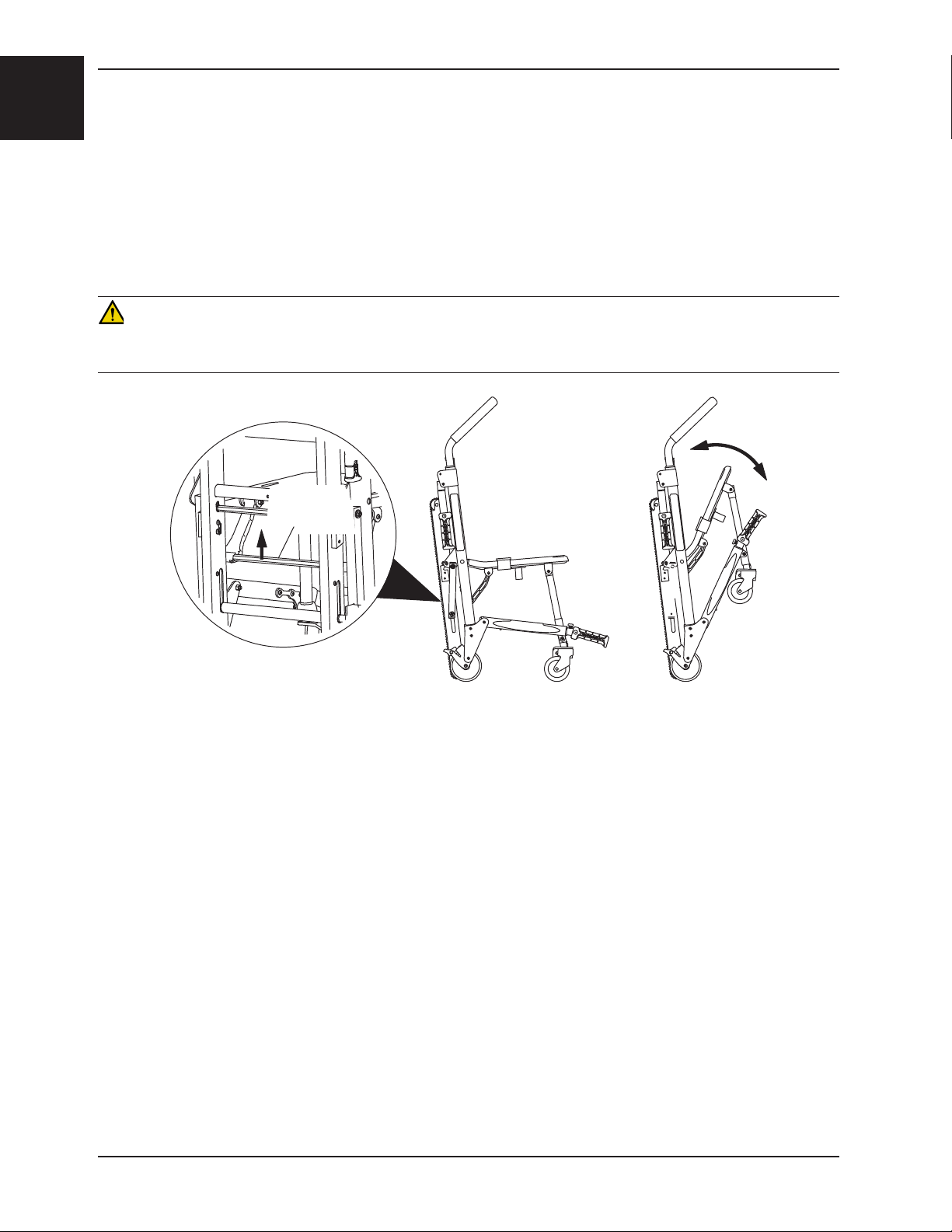
UNFOLDING THE CHAIR
To unfold the chair:
1. Stand behind the chair.
2. Apply the wheel locks (if desired).
3. Pull the backrest and the extension handle apart. The lock mechanism will automatically engage when the chair
is completely unfolded.
4. Verify the lock is engaged by pulling up on the seat. If the lock is properly engaged, the chair will not fold.
WARNING
An unlocked chair can fold during use, causing injury to the passenger or operator. Always make sure the chair is locked
in the unfolded position before use.
RED FOLD
LOCK BAR
Figure 1- Unfolding/Folding the Chair
FOLDING THE CHAIR
To fold the chair:
1. Apply the wheel locks (if desired). Buckle the restraint straps and fold them neatly to prevent them from interfering
with proper folding of the chair. Secure the head support strap behind the chair frame.
2. Stand at the side of the chair.
3. Pull up on the red lock bar at the rear of the chair.
4. Tip the chair forward.
5. Fold the seat up to the backrest until the front legs lock in the clips on the bottom of the seat tube.
Note: Rotate the front casters so they do not interfere with folding the chair.
Return To Table of Contents
1-12 6253- 001-166 RE V C www.stryker.com
Operation Guide
TRANSFERRING THE PASSENGER TO THE STRYKER EVACUATION CHAIR
To transfer the passenger to the chair:
1. Place the chair beside the passenger.
2. Apply the wheel locks to prevent the chair from moving.
3. Open the restraint straps.
4. Extend the upper control handle.
5. Transfer the passenger to the chair using accepted EMS procedures.
6. Use all the restraints to secure the passenger on the chair (page 1-14).
7. Disengage the wheel locks before transporting.
WARNING
The Stryker Evacuation Chair is not recommended for use with suspected cervical, spinal, or fracture injuries.
English
Return To Table of Contents
www.stryker.com 6253 -001-166 REV C 1-13
English
Operation Guide
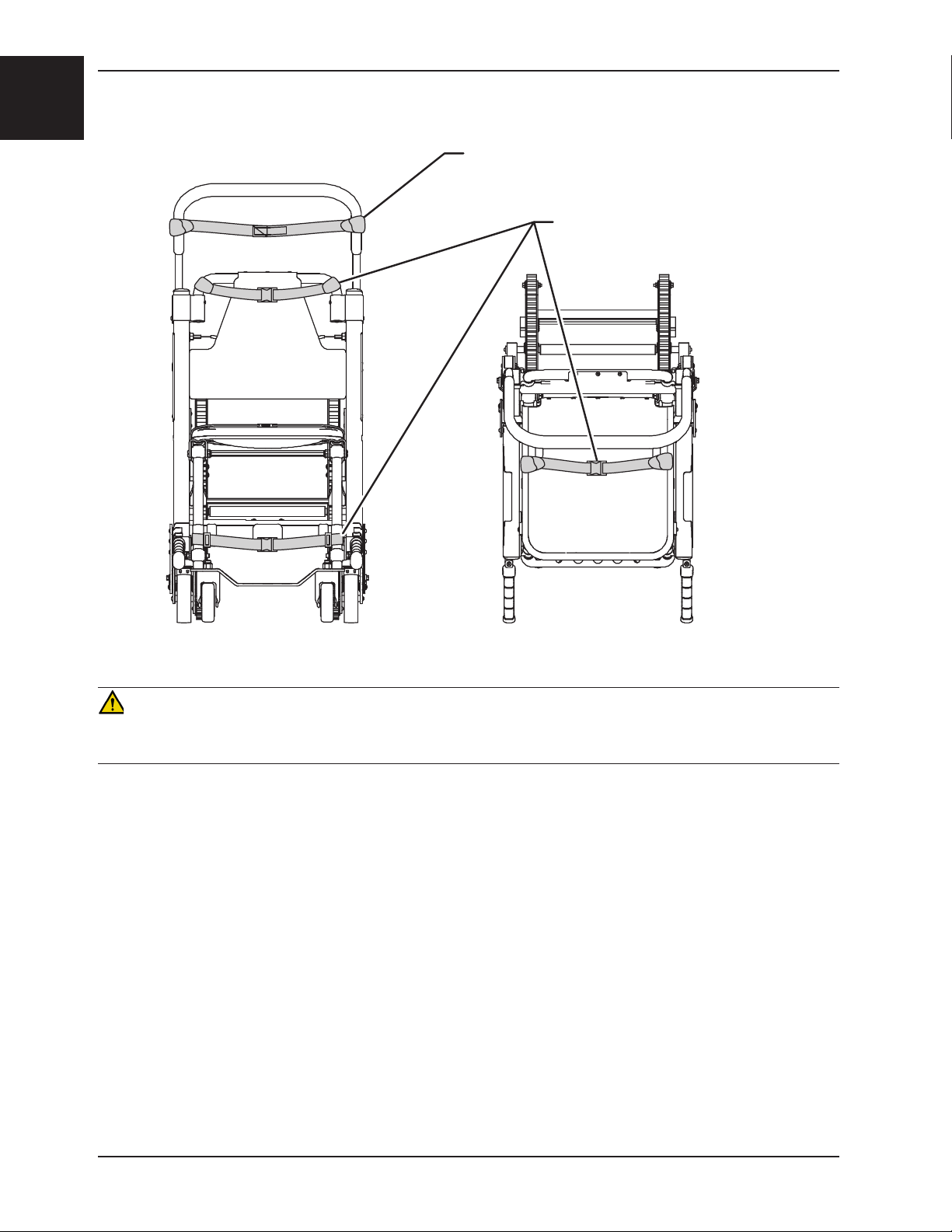
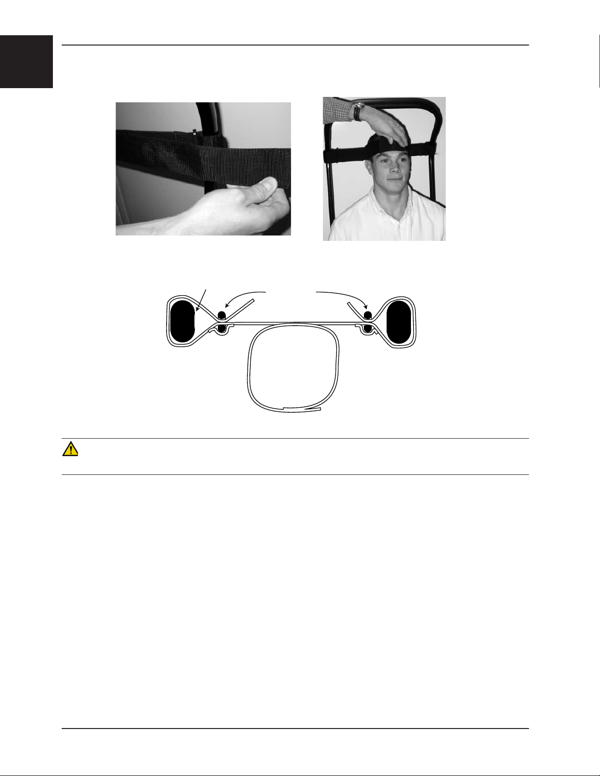
USING RESTRAINT STRAPS
HEAD SUPPORT
RESTRAINT STRAPS
Figure 2 - Strap Attachment Points
Front View
Figure 3 - Lap Strap Attachment Points
Top View
WARNING
Always use all restraint straps to secure the passenger on the chair. An unrestrained passenger may fall from the chair
and be injured.
Always secure the passenger on the chair with all restraint straps. Buckle one restraint across the passenger’s chest
and the other across the passenger’s lap. Buckle the ankle restraint across the passenger’s legs.
To avoid damage to the buckles and straps, keep the restraint straps buckled when the chair is not being used with a
passenger.
When attaching the restraint straps to the chair, remember the attachment points must provide strong anchorage and
proper restraint position while not interfering with equipment and accessories.
Return To Table of Contents
1-14 6253 -001-166 REV C www.stryker.com
Operation Guide
USING RESTRAINT STRAPS - CONTINUED
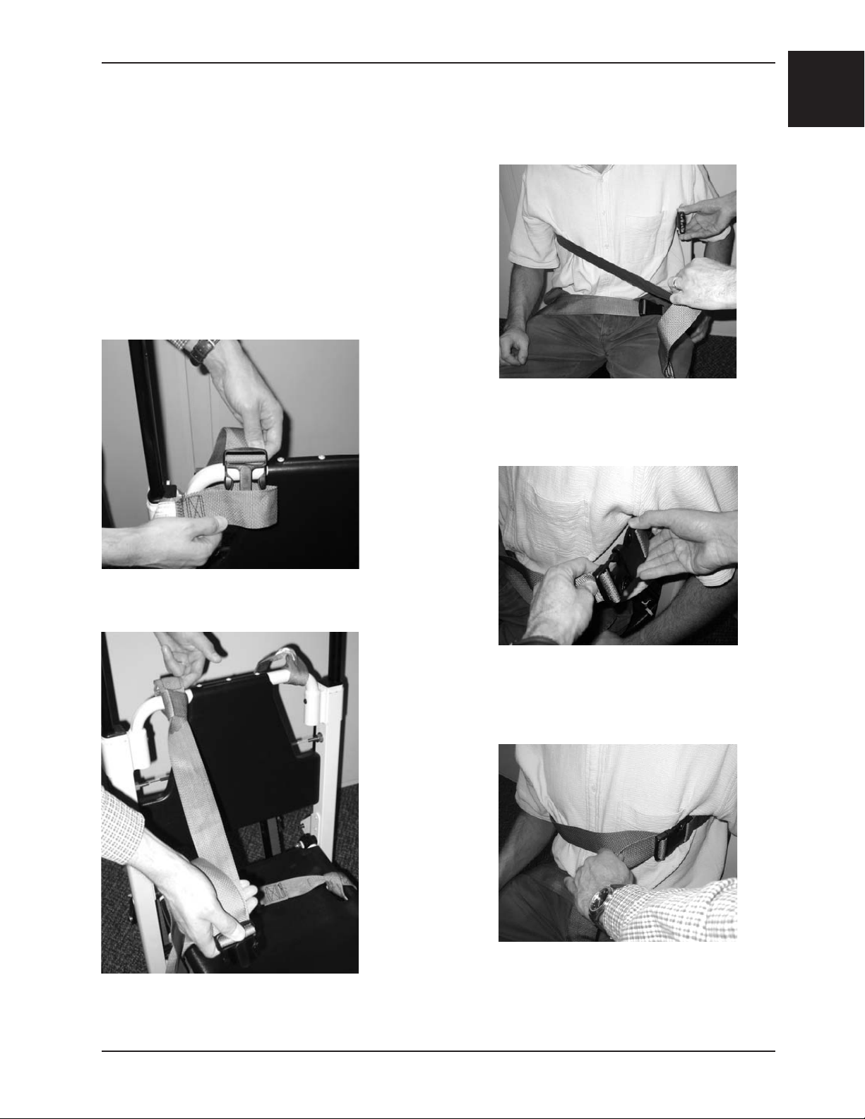
To attach the chest straps in the cross-chest configuration:
1. Wrap each strap around the chair frame, insert the end through
the loop on the end of the strap and pull it tight.
2. Pull the strap across the passenger’s chest, lengthening the
strap as necessary.
3. Buckle the strap.
4. Pull the loose end of the strap to tighten it securely around
the passenger.
5. Repeat for the second strap and the lap belt.
English
Figure 6 - Lengthen strap as necessary
Figure 4 - Insert the end through the loop
Figure 5 - Pull the strap tight
Figure 7 - Buckle strap
Figure 8 - Tighten strap securely
Return To Table of Contents
www.stryker.com 6253 -001-166 REV C 1-15
English
Operation Guide
USING RESTRAINT STRAPS - CONTINUED
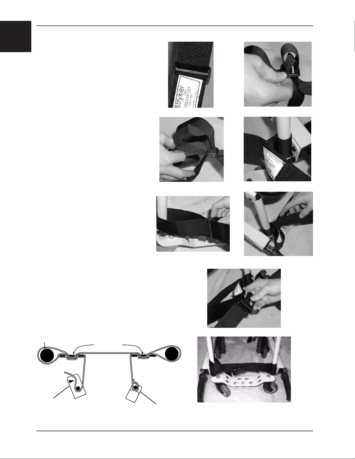
To attach the ankle strap:
1. Remove the three plastic pieces from the
strap.
2. Thread the strap through one of the
plastic “D” rings and slide the ring down to
the end of the strap up to the white label.
3. Loop the strap around the front leg of
the chair and pull the loose end of the
strap through the ring. Pull until the
ring rests against the foot rest tube.
4. Thread the strap through the other “D”
ring.
5. Loop the strap around the other front leg
of the chair and pull the loose end of
the strap through the loop. Pull until the
“D” ring rests against the foot rest tube.
6. Attach the final “male” end clip on the
strap.
Figure 9-17 - Attaching the leg strap
Return To Table of Contents
1-16 6253-001-166 REV C www.stryker.com

Operation Guide
USING RESTRAINT STRAPS - CONTINUED
• To lengthen the restraint, grasp the buckle, turn it at an angle to the webbing and pull it out. A hemmed tab at
the end of the webbing prevents the buckle from coming off the strap.
• To shorten the restraint, grasp the hemmed tab and pull the webbing back through the buckle until the required
tightness is achieved.
• When the chair is put into service, open the restraints and place them at either side of the chair until the passenger
is positioned on the seat. Lengthen the restraint, buckle it around the passenger and shorten it until the required
tightness to properly secure the passenger is achieved.
• To open the restraint, press the tabs on the side of the buckle to release the buckle and pull the tang out of the
receiver.
• To close the restraint, push the tang into the receiver until a “click” is heard.
• Whenever a restraint is buckled on a passenger, the attendant should verify the tang is locked and the extra
webbing is not tangled in the chair or hanging loose.
• Inspection of the restraints should be done at least once a month (more frequently if used heavily). Inspection
should include checking for a bent or broken receiver or tang, torn or frayed webbing, etc. Any restraint showing
wear or not operating properly must be replaced immediately.
English
PROPER LIFTING TECHNIQUES
When lifting the Stryker Evacuation Chair and passenger, remember these five basic guidelines:
• Keep your hands close to your body.
• Keep your back straight.
• Coordinate your movements with your partner and lift with your legs.
• Avoid twisting.
• Always operate the Stryker Evacuation Chair as described in this manual.
Return To Table of Contents
www.stryker.com 6253 -001-166 REV C 1- 17
English
Operation Guide
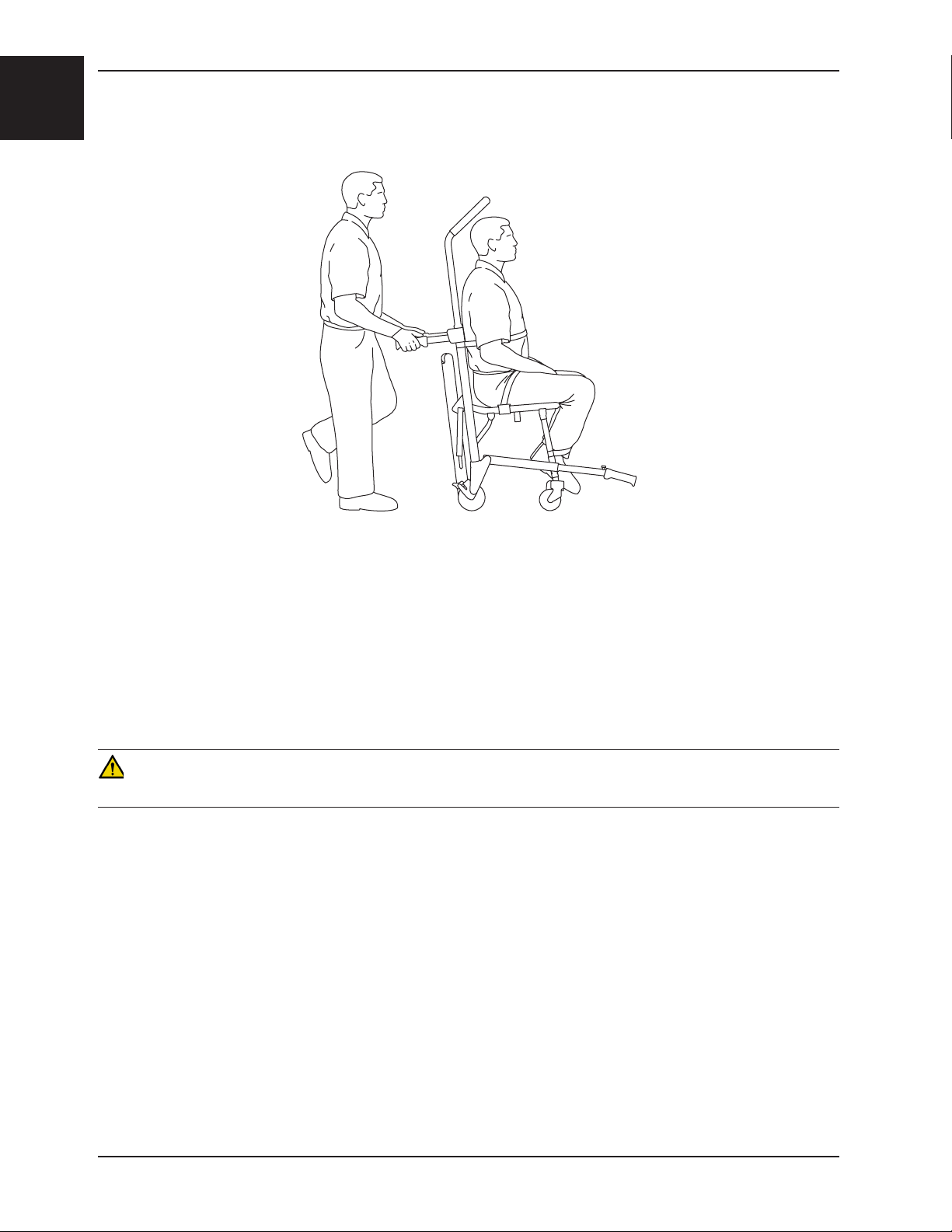
TRANSPORTING THE PASSENGER ON FLAT SURFACES
Figure 18 - Transporting the Passenger
To roll the Stryker Evacuation Chair over flat surfaces, push and guide the chair from the rear of the passenger, using
either the head end handles or the backrest tube. Lift the chair over and around obstructions with the head end and
foot end lift handles.
In addition to the head end lift handles, the extendable upper control handle can be used in any position to roll and
guide the chair. Extend the upper control handle by pulling the red release cable with one hand, and pulling up on the
control handle with the other. Release the cable to lock the handle in either the intermediate or fully extended position.
Lift the chair over and around obstructions with the head end and foot end lift handles.
CAUTION
Casters are not suitable for all surfaces. Caution should be used at all times.
Return To Table of Contents
1-18 6253-001-166 REV C www.stryker.com
Operation Guide
TRANSPORTING THE PASSENGER DOWN STAIRS
WARNING
• To avoid injury, always verify the Stair-TREAD™ system is locked
in place before transporting the passenger.
• To avoid injury when a passenger weighing more than 200 pounds
is on the chair, use a minimum of two operators to transport on
stairs. If more people are required to safely control the chair, see
page 1-25 for the proper positioning of each helper.
• To avoid injury, always verify the lift handles are locked in place
before using them to lift the chair.
English
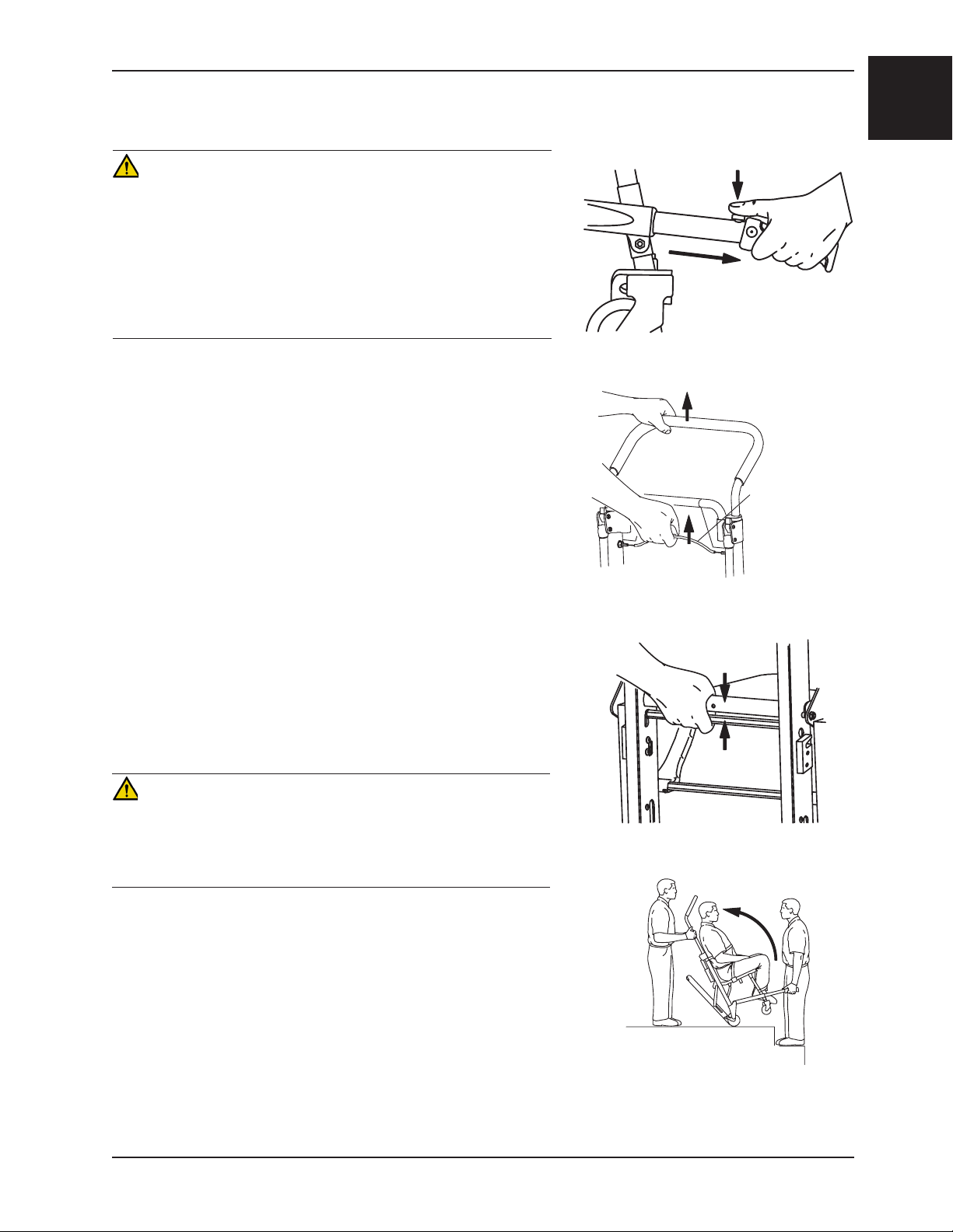
1. Roll the chair to the stairs and align it squarely with the edge of
the first step.
2. Foot end operator (if necessary) - Extend the foot end lift handles
by pushing the red release buttons and pulling the handles out
until they stop. Release the buttons and verify the handles are
locked.
3. Head end operator - Use one hand to pull the red upper control
handle release cable while using the other hand to pull up and
fully extend the handle. Release the cable and verify the handle
is locked on both sides in the fully extended position.
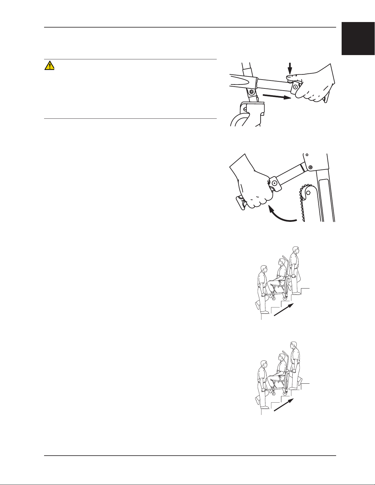
4. Head end operator - Squeeze the red track release bar against
the black cross tube. Relax your grip on the release bar and
forcefully pull the Stair-TREAD™ system to the fully extended
position until both sides lock securely. Always verify both sides of
the Stair-TREAD™ system are locked by trying to fold it back up.
CAUTION
Release the red track release bar before clicking the Stair-TREAD™
system into the locked position. Failure to follow this procedure could
result in the track failing to lock. Always verify the Stair-TREAD™
system is locked by trying to fold it before descending stairs.
Figure 19 - Foot end lift handles
Release Cable
Figure 20 - Upper control handle release
cable
Figure 21 - Red track release bar
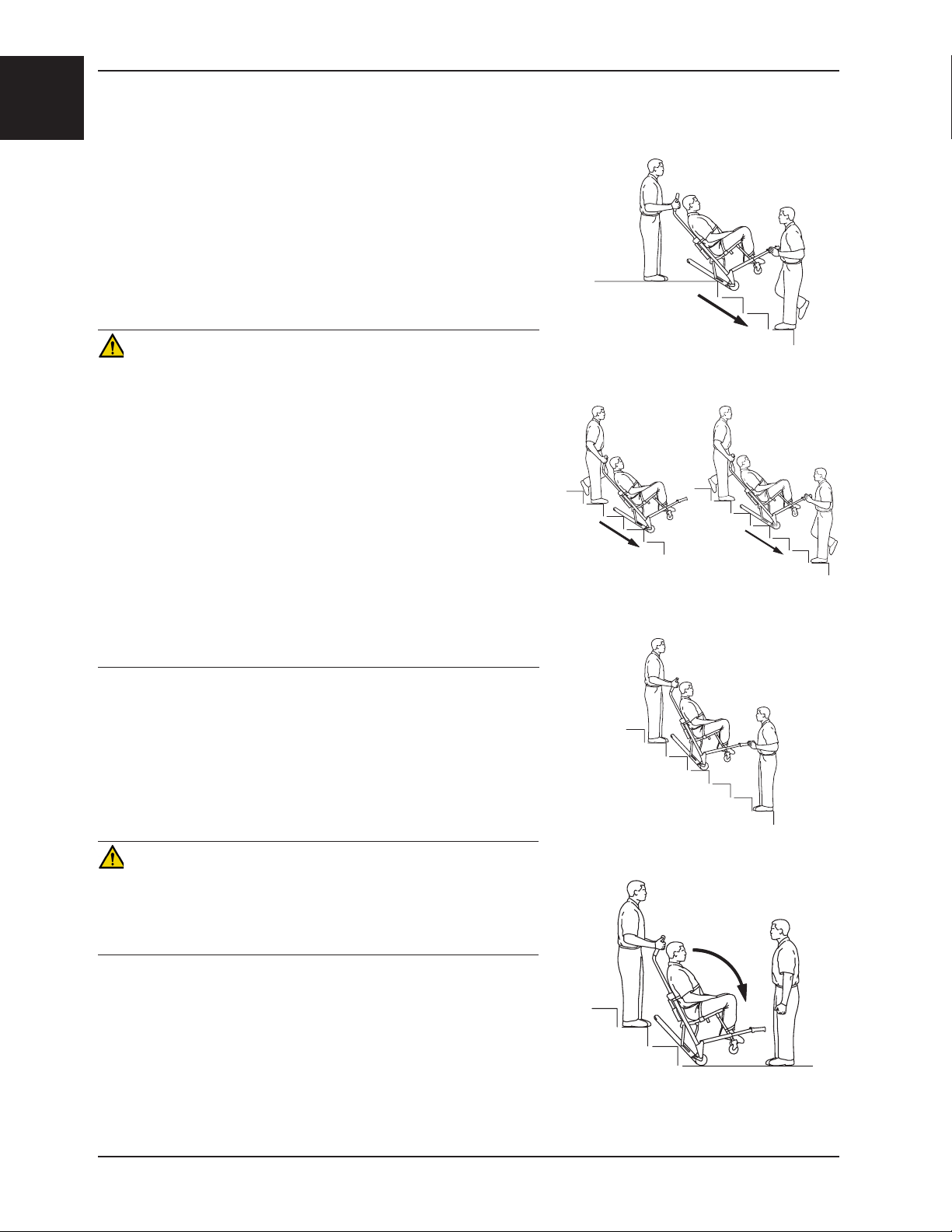
5. Operators face each other while descending the stairs.
6. Head end operator - Tilt the chair back just far enough to allow
the Stair-TREAD™ system to contact the floor.
Figure 22 - Tilt the chair
Return To Table of Contents
www.stryker.com 6253 -001-166 REV C 1-19
English
Operation Guide
TRANSPORTING THE PASSENGER DOWN STAIRS - CONTINUED
7. Both operators - Maintaining the angle, guide the Stryker
Evacuation Chair over the edge of the stairs, allowing the StairTREAD™ system to engage the first step.
8. Both operators - Glide down the stairs until the treads are level
across the edges of two or three steps.
9. Head end operator - Apply slight downward pressure on the
extendable upper control handle while the foot end operator
applies slight upward pressure on the foot end lift handles to
keep the chair from rocking forward as it glides down the stairs.
WARNING
• The Stair-TREAD™ system may not work the same on all
stair surfaces and in all environmental conditions. Based on
conditions, varying amounts of resistance may be encountered.
Avoid getting dirt or other obstructions inside the tracks. Water, ice
and/or debris on the stairs can affect operator footing and proper
operation of the Stair-TREAD™ system. To avoid injury, clear the
path or consider an alternate route. Condensation, water, ice and/
or debris on the Stair-TREAD™ system can cause unpredictable
performance, resulting in a sudden change in the weight the
operators must support.
• To avoid injury, and to aid proper operation of the Stair-TREAD™
system, ensure the belts are clean and dry before transporting the
passenger.
• To avoid injury to the operators and/or the passenger, operators
should never attempt to transport passenger loads greater than
what they can safely lift.
Figure 23 - Track engaging first step
Figure 24 - Transporting down the stairs
10. Foot end operator (if necessary) - when the track reaches the
last step, release the front handles. Head end operator - allow the
chair to tip forward until all four wheels are on the ground. Roll
the chair as described on page 1-18.
11. To fold the Stair-TREAD™ system, pull the red track release bar
toward the black cross bar and fold the track up toward the chair.
Verify the Stair-TREAD™ system is locked in place.
Figure 25 - “Resting position”
CAUTION
Release the red track release bar before clicking the Stair-TREAD™
system into the locked position. Failure to follow this procedure could
result in the track failing to lock. Always verify the Stair-TREAD™
system is locked by trying to fold it before descending stairs.
If, while descending the stairs, either operator needs to pause or rest,
tilt the chair forward just enough to allow the rear wheels to rest in
the crook of the stair. To continue down the stairs from the resting
position, the head end operator exerts slight downward pressure on
the upper control handle while the foot end operator provides slight
upward pressure to tilt the chair back and engage the Stair-TREAD™
system.
Return To Table of Contents
1-20 6253- 001-166 RE V C www.stryker.com
Figure 26 - Bottom of stairs
Operation Guide
TRANSPORTING THE PASSENGER UP STAIRS
WARNING
• To avoid injury when a passenger weighing more than 200 pounds
is on the chair, use a minimum of two operators to transport on
stairs. If more people are required to safely control the chair, see
page 1-25 for the proper positioning of each helper.
• To avoid injury, always verify the lift handles are locked in place
before using them to lift the chair.
English
1. Roll the chair to the bottom of the stairs with the passenger’s back
to the stairs.
2. Foot end operator - extend the foot end lift handles by pushing the
red buttons and pulling the handles until they stop. Release the
button and verify the handle is locked.
3. Head end operator - unfold the head end lift handles.
4. The foot end operator faces up the stairs. The head end operator
may either face backward for improved passenger monitoring or
forward for an improved view of the stairs and easier maneuvering
around obstacles.
Note: Although the head end operator can face either direction
while carrying, any applicable protocols for carrying chairs should
be followed.
5. Both operators - simultaneously lift the chair, using the head
and foot end lift handles and following proper lifting techniques
(see page 1-17). Carry the chair slowly up the stairs, avoiding any
obstructions.
Figure 27 - Foot end lift handles
Figure 28 - Head end lift handles
Figure 29 - Transporting up the stairs
Figure 30 - Transporting up the stairs
Return To Table of Contents
www.stryker.com 6253 -001-166 REV C 1-21
English
Operation Guide
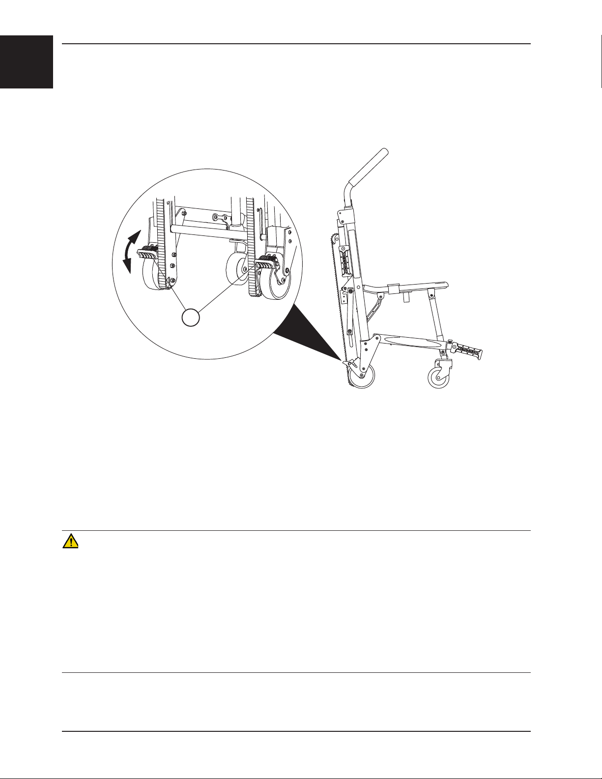
OPERATING THE WHEEL LOCKS
A
Figure 31 - Wheel Locks
To activate the wheel locks:
1. Press down on the pedals (A) until they stop.
2. To release the wheel locks, depress the upper face of the pedal with your foot or lift up with your toe under the
pedal. The upper portion of the pedal will rest against the chair frame when the wheel lock is released.
WARNING
• Only use wheel locks during passenger transfer or without a passenger on the chair. Tipping could occur if the
chair is moved while the wheel locks are applied, resulting in injury to the passenger or operator and/or damage
to the chair.
• Wheel locks are only intended to help prevent the empty chair from rolling while unattended, and to aid in
passenger transfer. A wheel lock may not provide sufficient resistance on all surfaces or under loads.
• Never leave a passenger unattended on the chair or injury could result. Hold the chair securely while a passenger
is on the chair.
• Never use a wheel lock on a chair with excessively worn wheels. Using a wheel lock on a wheel with less than a
5” diameter could compromise the holding ability of the wheel lock, possibly resulting in injury to the passenger or
operator and/or damage to the chair or other equipment.
Return To Table of Contents
1-22 6253- 001-166 RE V C www.stryker.com
Operation Guide
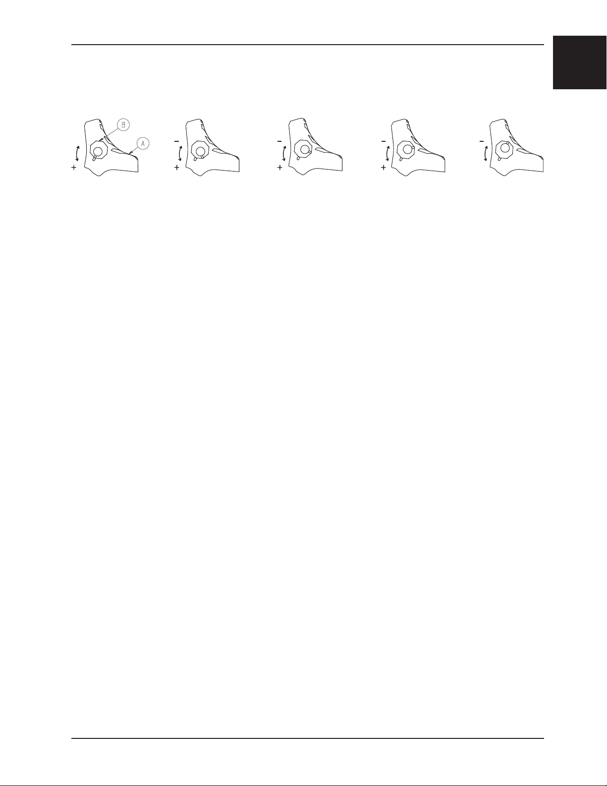
ADJUSTING THE WHEEL LOCKING FORCE
Minimum MaximumFigure 32 - Wheel locking force adjustment
To adjust the wheel locking force:
1. Remove the screw from the center of the lock pedal.
2. Remove the octagonal sleeve (B) from the pedal (A).
3. Rotate the octagonal sleeve counterclockwise to increase the pedal locking force or clockwise to decrease the
locking force.
4. Insert the octagonal sleeve (B) into the pedal (A).
5. Reinstall the screw into the center of the lock pedal.
6. Test the pedal locking force and verify that it holds properly before returning the chair to service.
English
Note: If, after adjustment, the pedal still does not hold the wheel properly, replace the wheel.
Return To Table of Contents
www.stryker.com 6253 -001-166 REV C 1-23
English
Operation Guide
USING THE HEAD SUPPORT
TOP VIEW
Upper Control Handle
Figures 33 - 35 - Attaching and using the head support
Slide Ring
Head Support
WARNING
The Stryker Evacuation Chair is not recommended for use with suspected cervical, spinal, or fracture injuries.
Before using the head support, the upper control handle must be extended. First, pull the red upper control handle
release cable with one hand. Then, pull up on the handle with the other hand. Release the cable and verify the handle
is securely locked into one of the two available positions.
To attach the head support to the extendable upper control handle:
1. Wrap the loose ends of the strap around the vertical portions of the handle, then feed them through the plastic
loops.
2. Pull tight, and secure the strap to itself.
3. Adjust the height by loosening the strap, moving it to the desired location, and tightening it again.
To support the passenger’s head, position at the base of the head. For unconscious, or semiconscious passengers,
secure the head using the other two parts of the strap. Wrap around the passenger’s head, and overlap the straps to
the desired tightness to secure. When not in use, these straps can be wrapped back around the handle and attached
to the back of the support.
Return To Table of Contents
1-24 6 253-001-166 REV C www.stryker.com
Operation Guide
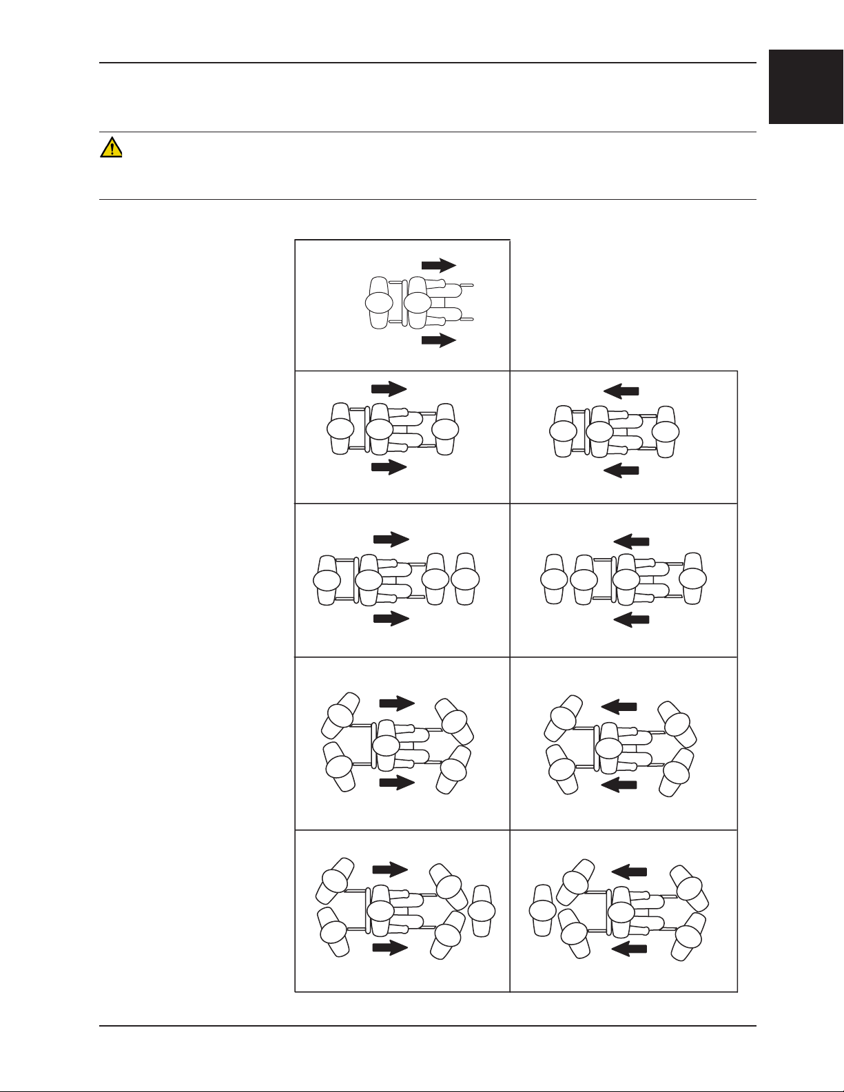
USING ADDITIONAL ASSISTANCE
WARNING
To avoid injury when a passenger weighing more than 200 pounds is on the chair, use a minimum of two operators to
transport on stairs.
Down Stairs Up Stairs
One Operator
Operator
Two Operators
English
Two Operators
One Helper
Two Operators
Two Helpers
Operator Operator
Operator OperatorHelper Helper OperatorOperator
Helper Operator
Operator
Helper Operator
Helper Operator
Helper
Operator Operator
Helper Operator
Helper Operator
Helper
Helper
Two Operators
Three Helpers
Operator
www.stryker.com 6253 -001-166 REV C 1-25
Helper
Operator
Helper
Return To Table of Contents
English
Operation Guide
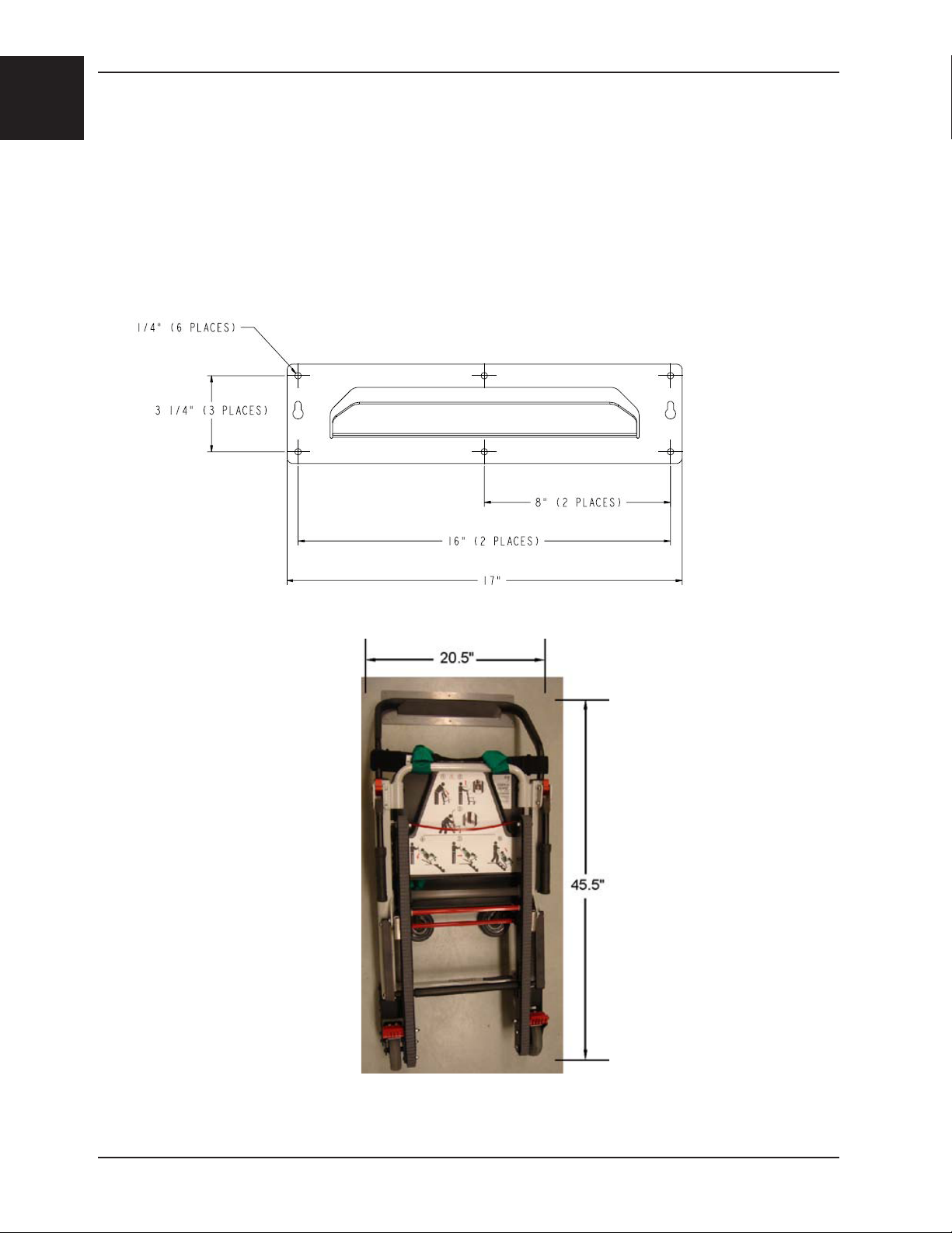
INSTALLING THE OPTIONAL WALL STORAGE BRACKET
To install the optional wall storage bracket:
1. Use the bracket as a template to mark the location of the mounting holes at the area where the wall brackets will
be installed. Consider the dimensions of the chair when selecting and marking the location. The approximate
height of the bracket from the floor should be 60 inches.
2. Using fasteners (not supplied) appropriate for the wall type, install the bracket by using at least four of the
mounting holes.
3. Hang the chair from the bracket using the upper control handle.
Figure 36 - Storage Bracket Dimensions
Figure 37 - Chair stored on the bracket
Return To Table of Contents
1-26 6253-001-166 REV C www.stryker.com
Operation Guide
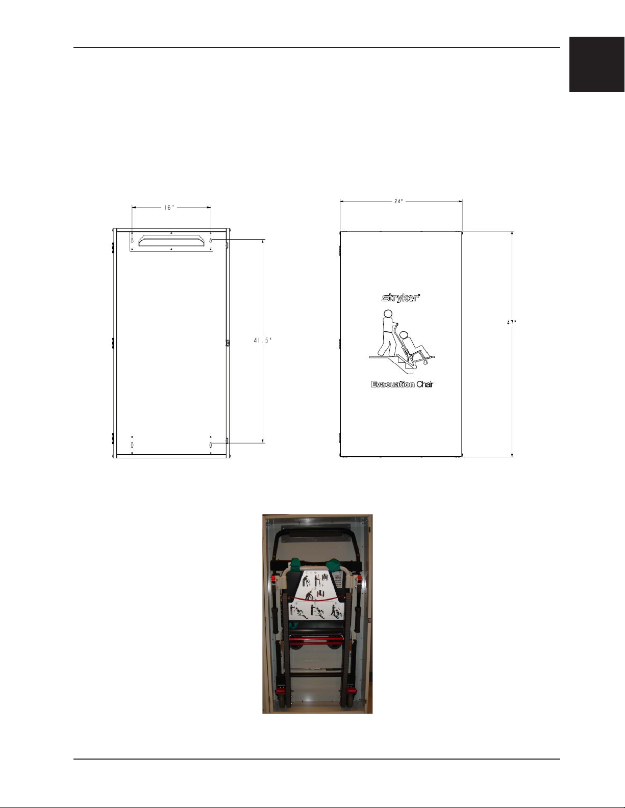
INSTALLING THE OPTIONAL CABINET
To install the optional cabinet:
1. Use the bracket as a template to mark the location of the mounting holes at the area where the cabinet will be
installed. Consider the dimensions of the cabinet when selecting and marking the location. The approximate
height of the bottom of the cabinet to the floor should be at least 12 inches.
2. Using fasteners (not supplied) appropriate for the wall type, install the cabinet by using at least four of the
mounting holes.
3. Hang the chair from the bracket using the upper control handle.
English
Figure 38 - Cabinet Dimensions
Figure 39 - Chair stored in the cabinet
Return To Table of Contents
www.stryker.com 6253 -001-166 REV C 1-27
English
Operation Guide
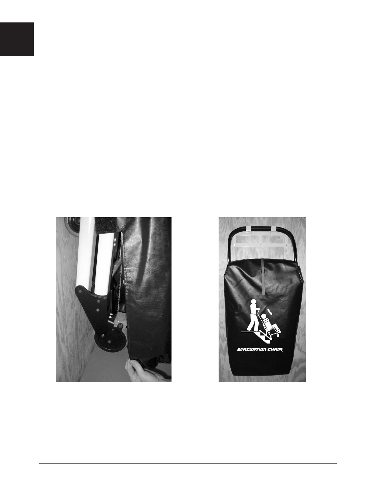
INSTALLING THE OPTIONAL COVER
Note: It is easiest to install the cover when the chair is hanging.
To install the optional vinyl cover:
1. Slip the bottom pocket over the wheels.
2. Wrap the side flaps around the chair frame.
3. Pull the top flat down between the bars of the upper control handle and over the head support strap.
4. Attach the Velcro strips.
5. Attach the red handle strip to the Velcro on the front of the cover.
REMOVING THE OPTIONAL COVER
To remove the optional vinyl cover:
1. Pull the red handle strip.
2. Allow the cover to drop off the chair.
Figure 40 - Slip the bottom pocket over the wheels Figure 41 - Cover fully installed on the chair
Return To Table of Contents
1-28 6253-001-166 REV C www.stryker.com
 Loading...