

Stryker 5050, 5051 Operation Manual
5050 & 5051 Stretcher Chair
OPERATIONS MANUAL
For Parts or Technical Assistance:
1-800-327-0770

Table of Contents
Introduction
Specifications 2. . . . . . . . . . . . . . . . . . . . . . . . . . . . . . . . . . . . . . . . . . . . . . . . . . . . . . . . . . . . . . . . . . . . . . . . . . . .
Warning / Caution / Note Definition 2. . . . . . . . . . . . . . . . . . . . . . . . . . . . . . . . . . . . . . . . . . . . . . . . . . . . . . . . .
Operation Guide
Base Pedal Operation 4. . . . . . . . . . . . . . . . . . . . . . . . . . . . . . . . . . . . . . . . . . . . . . . . . . . . . . . . . . . . . . . . . . . .
Raising And Lowering Litter Height 5. . . . . . . . . . . . . . . . . . . . . . . . . . . . . . . . . . . . . . . . . . . . . . . . . . . . . . . . .
Applying the Brake System 5. . . . . . . . . . . . . . . . . . . . . . . . . . . . . . . . . . . . . . . . . . . . . . . . . . . . . . . . . . . . . . . .
Operating the Steer Caster 5. . . . . . . . . . . . . . . . . . . . . . . . . . . . . . . . . . . . . . . . . . . . . . . . . . . . . . . . . . . . . . . .
Trendelenburg/Reverse Trendelenburg Positioning 6. . . . . . . . . . . . . . . . . . . . . . . . . . . . . . . . . . . . . . . . . . . .
Using the Siderails 6. . . . . . . . . . . . . . . . . . . . . . . . . . . . . . . . . . . . . . . . . . . . . . . . . . . . . . . . . . . . . . . . . . . . . . .
Using the Patient Transfer System 7. . . . . . . . . . . . . . . . . . . . . . . . . . . . . . . . . . . . . . . . . . . . . . . . . . . . . . . . . .
Operating the Fowler 8, 9. . . . . . . . . . . . . . . . . . . . . . . . . . . . . . . . . . . . . . . . . . . . . . . . . . . . . . . . . . . . . . . . . . .
Operating the Adjustable Foot Rest 10. . . . . . . . . . . . . . . . . . . . . . . . . . . . . . . . . . . . . . . . . . . . . . . . . . . . . . . .
Operating the Optional Independent Foot Section
Dependent (Chair Mode) Operation 11. . . . . . . . . . . . . . . . . . . . . . . . . . . . . . . . . . . . . . . . . . . . . . . . . . . . . .
Independent Operation 11. . . . . . . . . . . . . . . . . . . . . . . . . . . . . . . . . . . . . . . . . . . . . . . . . . . . . . . . . . . . . . . .
Resetting the Foot Section (Returning To Chair Mode) 11. . . . . . . . . . . . . . . . . . . . . . . . . . . . . . . . . . . . .
Positioning the Push Bar 12. . . . . . . . . . . . . . . . . . . . . . . . . . . . . . . . . . . . . . . . . . . . . . . . . . . . . . . . . . . . . . . . .
Removing And Reinstalling the Mattress 12. . . . . . . . . . . . . . . . . . . . . . . . . . . . . . . . . . . . . . . . . . . . . . . . . . . .
Operating the Enhanced Clearance Head Piece 13. . . . . . . . . . . . . . . . . . . . . . . . . . . . . . . . . . . . . . . . . . . . .
Using the Optional Inflatable Head Support Cushion 13. . . . . . . . . . . . . . . . . . . . . . . . . . . . . . . . . . . . . . . . .
Using the Optional Wrist Rests 14. . . . . . . . . . . . . . . . . . . . . . . . . . . . . . . . . . . . . . . . . . . . . . . . . . . . . . . . . . . .
Using the Optional Tethered I.V. Pole 14. . . . . . . . . . . . . . . . . . . . . . . . . . . . . . . . . . . . . . . . . . . . . . . . . . . . . .
Preventative Maintenance
Cleaning 15. . . . . . . . . . . . . . . . . . . . . . . . . . . . . . . . . . . . . . . . . . . . . . . . . . . . . . . . . . . . . . . . . . . . . . . . . . . . . . .
Checklist 16. . . . . . . . . . . . . . . . . . . . . . . . . . . . . . . . . . . . . . . . . . . . . . . . . . . . . . . . . . . . . . . . . . . . . . . . . . . . . . .
Limited Warranty
Obtaining Parts and Service 17. . . . . . . . . . . . . . . . . . . . . . . . . . . . . . . . . . . . . . . . . . . . . . . . . . . . . . . . . . . . .
Supplemental Warranty Coverage 17. . . . . . . . . . . . . . . . . . . . . . . . . . . . . . . . . . . . . . . . . . . . . . . . . . . . . . . .
Return Authorization 18. . . . . . . . . . . . . . . . . . . . . . . . . . . . . . . . . . . . . . . . . . . . . . . . . . . . . . . . . . . . . . . . . . . .
Freight Damage Claims 18. . . . . . . . . . . . . . . . . . . . . . . . . . . . . . . . . . . . . . . . . . . . . . . . . . . . . . . . . . . . . . . . .

Introduction
INTRODUCTION
This manual is designed to assist you with the operation of the 5050 & 5051 Stretcher Chair. Read it thoroughly before using the equipment.
SPECIFICATIONS
Maximum Weight Capacity 400 pounds
Overall Stretcher Length/Width 76”/30”
Patient Surface Length/Width (Mattress) 74”/24”
Minimum/Maximum Stretcher Height (Floor to Litter Surface) 22”/33.5”
Foot Section Articulation 0_ to 80_
Fowler Articulation 0_ to 90_
Trendelenberg/Reverse Trendelenberg Articulation +18_/-18 _
Stryker reserves the right to change specifications without notice.
WARNING / CAUTION / NOTE DEFINITION
The words WARNING, CAUTION and NOTE carry special meanings and should be carefully reviewed.
WARNING
The personal safety of the patient or user may be involved. Disregarding this information could result in injury
to the patient or user.
CAUTION
These instructions point out special procedures or precautions that must be followed to avoid damaging the
equipment.
NOTE
This provides special information to make maintenance easier or important instructions clearer.
2

Introduction
Before operating this stretcher, it is important to read and understand all information in this manual.
Carefully read and strictly follow the warnings listed on this page.
WARNING
Patient entry, egress and transfer from the Model 5050 & 5051 Stretcher Chair must always be done at the
center side locations with the siderail lowered. At no time should patients be allowed to enter or exit from
the ends of the Stretcher Chair, unless it is in the full chair position (back section up/foot section down). Improper entry, egress or transfer may cause the Stretcher Chair to tip or become unstable which may result
in patient injury.
To avoid risk of tipping resulting in patient injury, never leave the Stretcher Chair unattended in the horizontal
position. Always return the unit to the chair position when not in use. Warning labels are located at the head
and foot end of the Stretcher Chair frame stating: “DO NOT SIT ON END. TIPPING MAY OCCUR. KEEP
IN THE CHAIR POSITION WHEN NOT IN USE.”
Always apply the caster brakes when a patient is getting on or off the stretcher. Push on the stretcher to ensure the brakes are securely locked. Always engage the brakes unless the stretcher is being moved. Injury
could result if the stretcher moves while a patient is getting on or off the stretcher . I f brakes do not hold properly, refer to your stretcher maintenance manual for a brake adjustment procedure.
Be sure to remove any equipment that may be in the way before lowering the Stretcher Chair or damage could
occur to the equipment or the Stretcher Chair.
Be sure the siderail latching mechanism is working properly and the siderail is latching securely at all times
or patient injury could result. If the siderails are not latching properly, refer to your stretcher maintenance
manual for adjustment details.
To avoid having the siderail swing down freely when the latch is released, securely hold the siderail either
underneath or from the end when raising or lowering it. Failure to do so could cause damage to the Stretcher
Chair or injury to the user.
To avoid possible injury, patients should be appropriately restrained at all times.
When using the patient transfer system, always lock the brakes on all stretchers or beds being used and
always be sure the transfer surface is securely on the surface of the mating stretcher or bed. The Stretcher
Chair patient surface and the surface of the mating stretcher or bed must be at the same height before the
patient is transferred. Failure to follow these guidelines may result in an unstable surface and patient injury .
Be sure the brakes on both the Stretcher Chair and the mating bed or stretcher have been applied before
proceeding with the patient transfer.
Keep fingers/hands clear of the area between the frame and the Fowler when lowering the Fowler or injury
could result.
Hold the foot rest firmly while repositioning it to prevent it from falling to the lowest position and causing injury
or equipment damage.
Do not stand on the foot rest. Tipping may occur which could result in patient or user injury.
The foot section will release during the return to dependent operation (Chair Mode). Hold the end securely
and support it when repositioning.
The weight of the patient’s head is resting on the head piece and must be supported by the operator when
the latches are released and the head piece is being positioned. Failure to adequately support the head piece
while positioning the head could result in patient injury.
CAUTION
The dual articulating headpiece is designed to provide precision surgical positioning. Be sure to treat it with
care. The unit should be routinely checked to ensure optimal performance. In the event of any impact or
overload of the headpiece, be sure the unit is working properly and supports the intended load. Verify the
adjustment gears lock and release properly and, if necessary, refer to the adjustment procedure in the maintenance manual.
3
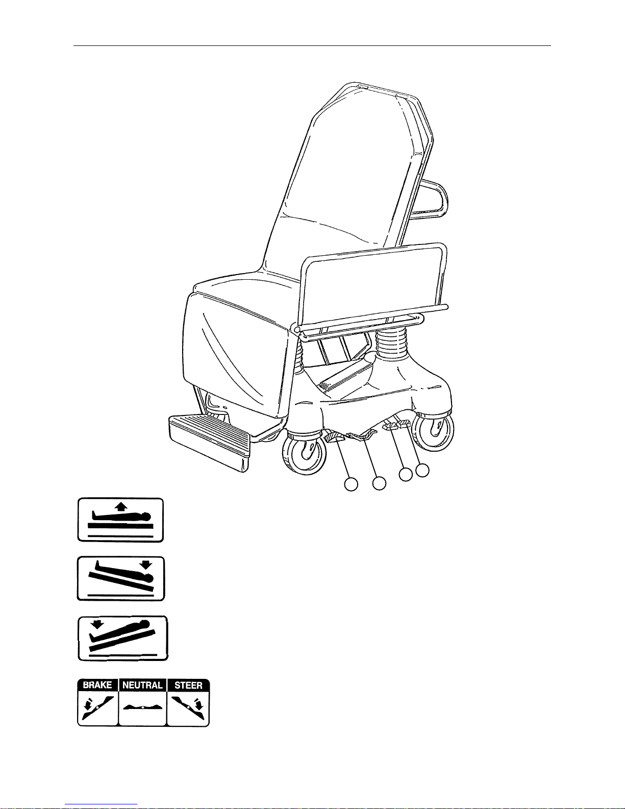
BASE PEDAL OPERATION
Operation Guide
B
C
D
A
(A)
Pump to raise litter.
(B) Depress to lower head end (Trendelenburg).
(C) Depress to lower foot end (Reverse Trendelenburg).
To lower both ends of the stretcher, depress
both Trendelenburg pedals at the same time.
(D) Brake and Steer functions
4

Operation Guide
WARNING
Patient entry, egress and transfer from the Model 5050 Stretcher Chair must always be done at the center
side locations with the siderail lowered. At no time should patients be allowed to enter or exit from the ends
of the Stretcher Chair, unless it is in the full chair position (back section up/foot section down). Improper entry ,
egress or transfer may cause the Stretcher Chair to tip or become unstable which may result in patient injury .
RAISING AND LOWERING LITTER HEIGHT
NOTE
For user convenience, pump pedals and control pedals are located on both sides of the Stretcher Chair.
CAUTION
Be sure to move any equipment that may be in the way before raising or lowering the Stretcher Chair height
or damage could occur to the equipment or the Stretcher Chair.
To raise the litter height, pump foot pedal (A) repeatedly until desired height is achieved. (See illustration,
page 4).
To lower the litter height, activate both pedals (B) and (C) using the same foot. Depress pedal (B) to lower
the head end only and depress pedal (C) to lower the foot end only of the Stretcher Chair. (See illustration,
page 4).
WARNING
To avoid risk of tipping resulting in patient injury, never leave the Stretcher Chair unattended in the horizontal
position. Always return the unit to the chair position when not in use. Warning labels are located at the head
and foot end of the Stretcher Chair frame stating: “DO NOT SIT ON END. TIPPING MAY OCCUR. KEEP
IN THE CHAIR POSITION WHEN NOT IN USE.”
APPLYING THE BRAKE SYSTEM
To engage the brakes on the Stretcher Chair, push fully down on the side of pedal (D) closest to the head
end of the stretcher. (See illustration page 4).
WARNING
Always apply the caster brakes when a patient is getting on or off the stretcher. Push on the stretcher to ensure the brakes are securely locked. Always engage the brakes unless the stretcher is being moved. Injury
could result if the stretcher moves while a patient is getting on or off the stretcher . I f brakes do not hold properly, refer to your stretcher maintenance manual for a brake adjustment procedure.
NOTE
For user convenience, the Brake/Steer pedal is located on both sides of the Stretcher Chair.
OPERATING THE STEER CASTER
To engage the steer caster, push fully down on the side of pedal (D) closest to the foot end of the stretcher
(See illustration page 4). This will lock the steering caster (foot end, right). The Stretcher Chair will pivot
around it when cornering.
5
 Loading...