

Structural Concepts FSI856R, FSI656R, FSI663R, FSE663R, FSI863R Installation & Operating Manual
READ AND SAVE THESE INSTRUCTIONS
INSTALLATION &
SCC P/N
OPERATING MANUAL
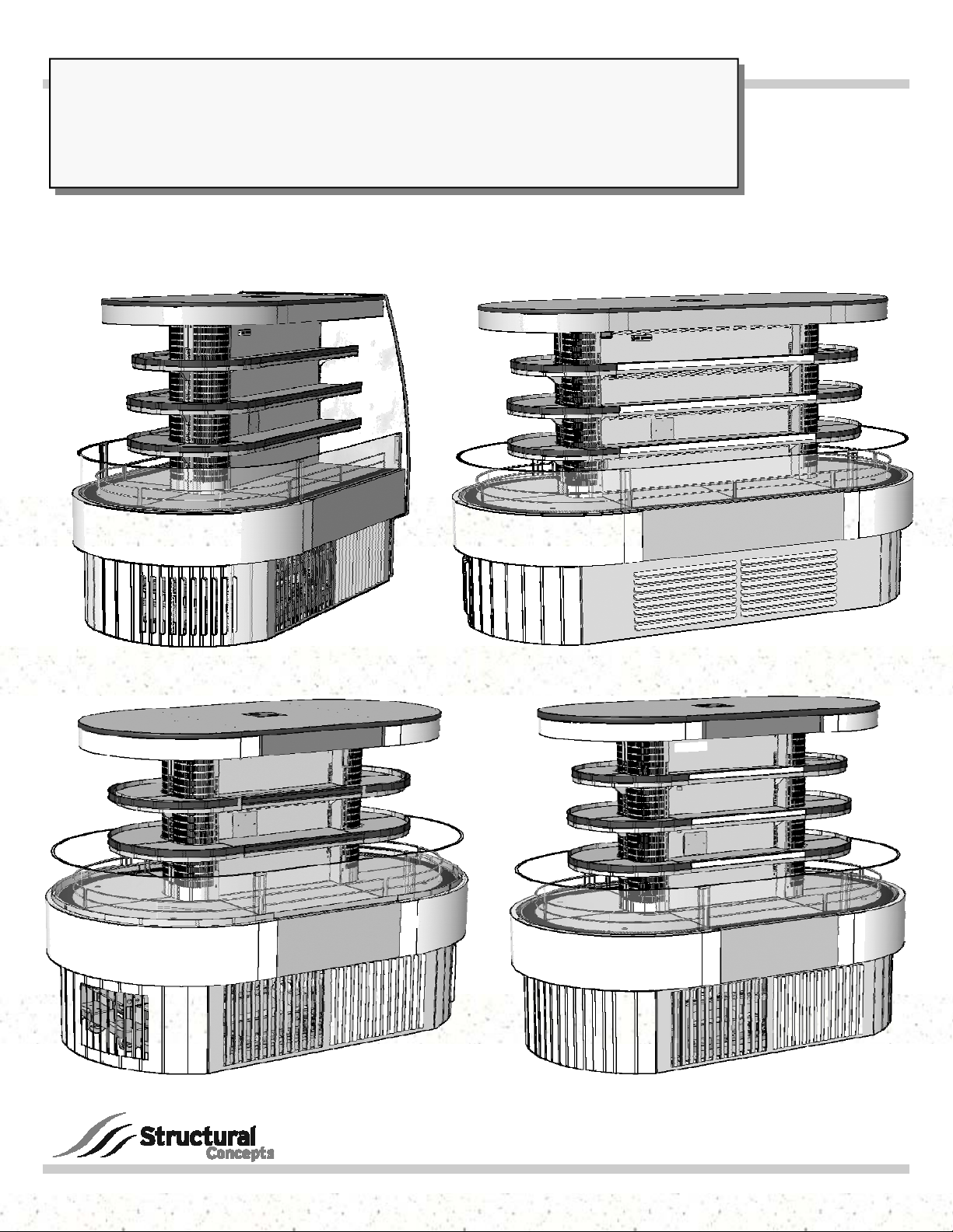
> REFRIGERATED SELF-SERVICE ISLAND - CID MODELS FSI856R, FSI656R, FSI663R and FSI863R
> REFRIGERATED SELF-SERVICE PENINSULA END CAP - CID MODEL FSE663R
20-20438
Model FSE663R
Model FSI656R
Model FSI863R
Model FSI663R
888 E. Porter Road · Muskegon, MI 49441 Phone: 231.798.8888 Fax: 231.798.4960 www.structuralconcepts.com
Specialty / Refrig Self-Svc Island & End Cap CID Case Manual_20-20438.pub
Rev J Date: 5.1.2017
TABLE OF CONTENTS
OVERVIEW / TYPE / COMPLIANCE / WARNINGS / PRECAUTIONS / WIRING DIAGRAM ..............
SHIPPING BRACKET PURPOSE / REMOVAL METHOD and DISPOSAL …………………………….
KICK PANEL REMOVAL / REMOVAL OF CASE FROM PALLET / POSITIONING UNIT ………..….
LEVELING UNIT / SHIMMING FRAME SUPPORT RAILS (REMOTE UNITS ONLY) …………......….
CASTER SYSTEM (OPTIONAL) / LEVELERS (SELF-CONTAINED UNITS ONLY) ...………………..
CEILING ORIGINATED ELECTRICAL & REFRIGERATION LINES / KNOCKOUT REMOVAL /
SEALING INLET & OUTLET …..................................................................................................
REMOTE CASES: REFRIGERATION LINE FIELD CONNECTION ……….…………………….…...….
REMOTE CASES: CONDENSATE PUMP LOCATION AND PURPOSE ………………………….……
FIELD WIRING BOX / DATA COLLECTION CABLE / MAIN POWER SWITCH ..…………………....
SELF-CONTAINED UNITS: TOE-KICK ATTACHMENT INSTRUCTIONS (HORIZ. vs. VERTICAL) ..
PLAN-O-GRAM (LOAD LEVEL GUIDELINES) …………………………………....……………………….
THERMOMETERS (DIGITAL THERMOMETER & OPTIONAL “CHECK TEMPERATURE”) …..…...
POWER-UP CHECK (EVAPORATOR FAN AREA) ...……………………………………………………..
MAINTENANCE FUNDAMENTALS: SHELF & BRACKET ASSEMBLY REMOVAL ………………...
MAINTENANCE FUNDAMENTALS: LED LIGHT FIXTURES / REMOVAL / REPLACEMENT ……..
REFRIGERATION FUNDAMENTALS: REMOTE DRAIN LAYOUT ...…....……………...……….……..
REFRIGERATION FUNDAMENTALS: SELF-CONTAINED DRAIN LAYOUT ………………….……...
REFRIGERATION FUNDAMENTALS: CONDENSATE PACKAGE ACCESS ………………….……...
REFRIGERATION FUNDAMENTALS: CONDENSATE PACKAGE ILLUSTRATED PARTS
BREAKDOWN ………………………………………………………………………………………….
GENERAL CLEANING (BY STORE PERSONNEL) ………………………...…………………………….
GENERAL CLEANING (BY STORE PERSONNEL) - CONDENSER C OIL AIR FILTER ……………..
PREVENTIVE MAINTENANCE (TO BE PERFORMED BY TRAINED SERVICE PROVIDERS ONLY
PREVENTIVE MAINTENANCE: HONEYCOMB AIR DIFFUSERS (TO BE PERFORMED BY
TRAINED SERVICE PROVIDERS ONLY) .………………………………………………………....
TROUBLESHOOTING (TO BE PERFORMED BY STORE PERSONNEL) ……………………………..
TROUBLESHOOTING (TO BE PERFORMED BY TRAINED SERVICE PROVIDERS ONLY) ……….
TROUBLESHOOTING: CONDENSING SYSTEM (BY TRAINED SERVICE PROVIDERS ONLY) .....
TROUBLESHOOTING: EVAPORATOR SYSTEM (BY TRAINED SERVICE PROVIDERS ONLY) …
SERIAL LABEL LOCATION & INFORMATION LISTED / TECH INFO & SERVICE………………......
CAREL® CONTROLLER: PROGRAMMING THE INSTRUMENT….……………………...….…….......
CAREL® CONTROLLER: USER INTERFACE, SUMMARY TABLES OF ALARMS & SIGNALS ….
CAREL® CONTROLLER: Summary Table of Operating Parameters (After Programming Key) ..
TECHNICAL SERVICE CONTACT INFORMATION & WARRANTY INFORMATION ..…………….....
3-4
5
6
7
8
9
10
11
12
13
14
15
16
17
18
19
20
21
22
23
24
25
26
27
28-29
30
31
32
33
34
35
36
2

OVERVIEW / TYPE / COMPLIANCE / WARNINGS / PRECAUTIONS / WIRING DIAGRAM - PAGE 1 of 2
OVERVIEW
These Structural Concepts merchandisers are
designed to merchandise packaged products at 41 °F
(5 °C) or less product temperatures.
Cases should be installed and operated according to
this operating manual’s instructions to ensure proper
performance.
Improper use will void warranty.
CID UNITS - TYPE 2 CONDITIONS
These units are designed for the display of products in
ambient store conditions where temperatures and
humidity are maintained within a specific range.
These CID units are designed for Type 2 conditions.
Type 2 conditions are ambient conditions of 55%
maximum humidity and maximum temperatures of
80 °F (27 °C).
This equipment MUST be installed in compliance with
all applicable NEC, federal, state and local
ATTENTION
CONTRACTORS
COMPLIANCE
Performance issues when in violation of applicable
NEC, federal, state and local electrical and plumbing
codes are not covered by warranty.
See below compliance guideline.
WARNINGS
This sheet contains important warnings to prevent
injury or death.
Please read carefully!
PRECAUTIONS, MAINTENANCE & WIRING DIAGRAM
INFORMATION
See next page for PRECAUTIONS, MAINTENANCE
and WIRING DIAGRAM information.
COMPLIANCE
electrical and plumbing codes.
WARNING
ELECTRICAL
HAZARD
WARNING
KEEP
HANDS
WARNING
Risk of electric shock. Disconnect power before servicing unit.
CAUTION! More than one source of electrical supply is
employed with units that have separate circuits.
Disconnect ALL ELECTRICAL SOURCES before servicing.
WARNING
Hazardous moving parts. Do not operate unit with covers removed.
Fan blades may be exposed when deck panel is removed.
Disconnect power before removing deck panel.
WARNING! POWER CORD AND PLUG MAINTENANCE
Risk of electric shock. If cord or plug becomes damaged,
replace only with cord and plug of same type.
3

OVERVIEW / TYPE / COMPLIANCE / WARNINGS / PRECAUTIONS / WIRING DIAGRAM - PAGE 2 of 2
PRECAUTIONS
This sheet contains important precautions to prevent
damage to unit or merchandise.
Please read carefully!
See previous page for specifics on OVERVIEW,
CONDITION TYPE, COMPLIANCE and WARNINGS.
CAUTION! LED LAMP REPLACEMENT GUIDELINES
CAUTION
LED lamps reflect specific size, shape and overall design.
Any replacements must meet factory specifications.
CAUTION! GFCI BREAKER USE REQUIREMENT
If N.E.C. (National Electric Code) or your local code
requires GFCI (Ground Fault Circuit Interrupter) protection,
you MUST use a GFCI breaker in lieu of a GFCI receptacle.
CAUTION
Performance issues caused by adverse conditions are NOT warranted.
End panels must be tightly joined or kept at least 6-inches away from
CAUTION! ADVERSE CONDITIONS / SPACING ISSUES
any structure to prevent condensation.
Unit must be kept at least 15-feet from exterior doors, overhead HVAC
vents or any air curtain disruption to maintain proper temperatures.
Unit must not be exposed to direct sunlight or any heat source.
Self-Contained Unit Clearance: 4” min. air intake / 4” min. air discharge.
WIRING DIAGRAM
Each case has its own wiring diagram folded and in
its own packet.
Wiring diagram placement may vary; it may be
placed near ballast box, field wiring box, raceway
cover, or other related location.
CAUTION! CHECK CONDENSATE PUMP CONNECTIONS
Water on flooring can cause extensive damage!
Carefully check the following before powering up case:
Condensate pump must be plugged into receptacle.
Condensate lines must be connected to condensate pump.
CAUTION! CHECK BOTH CONDENSATE PAN AND OVERFLOW PA N
Water on floor can cause extensive damage! Before powering up unit:
Condensate pan MUST BE positioned directly under condensate drain.
Overflow pan MUST HAVE single plug connected to its box. Units with
optional Clean Sweep™ MUST HAVE two plugs connected.
CAUTION! DO NOT RELY ON THERMOMETERS OR THERMOSTATS
FOR ACTUAL PRODUCT (FOOD) TEMPERATURES.
Thermometers and thermostats re flect air temperatures ONLY.
For ACTUAL food temperatures, use a calibrated food thermometer.
4
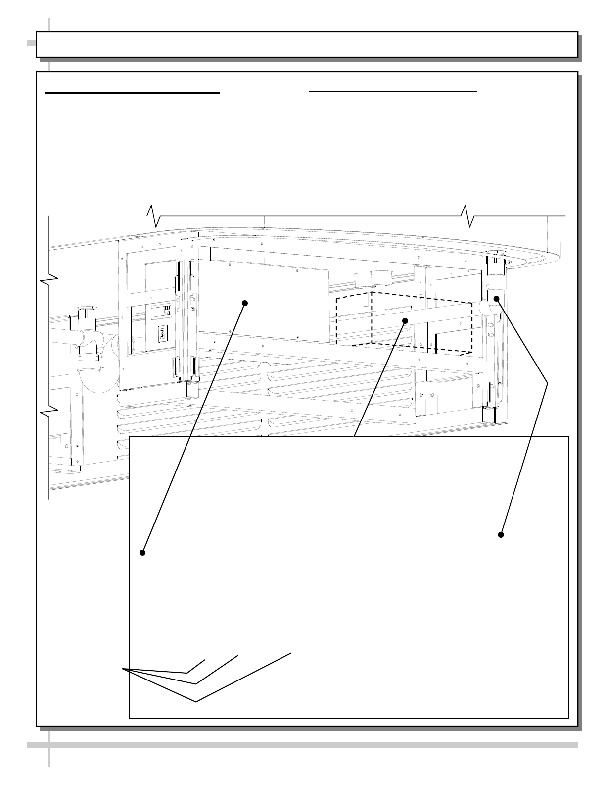
SHIPPING BRACKET PURPOSE / REMOVAL METHOD and DISPOSAL / SHIPPING BRACE REMOVAL
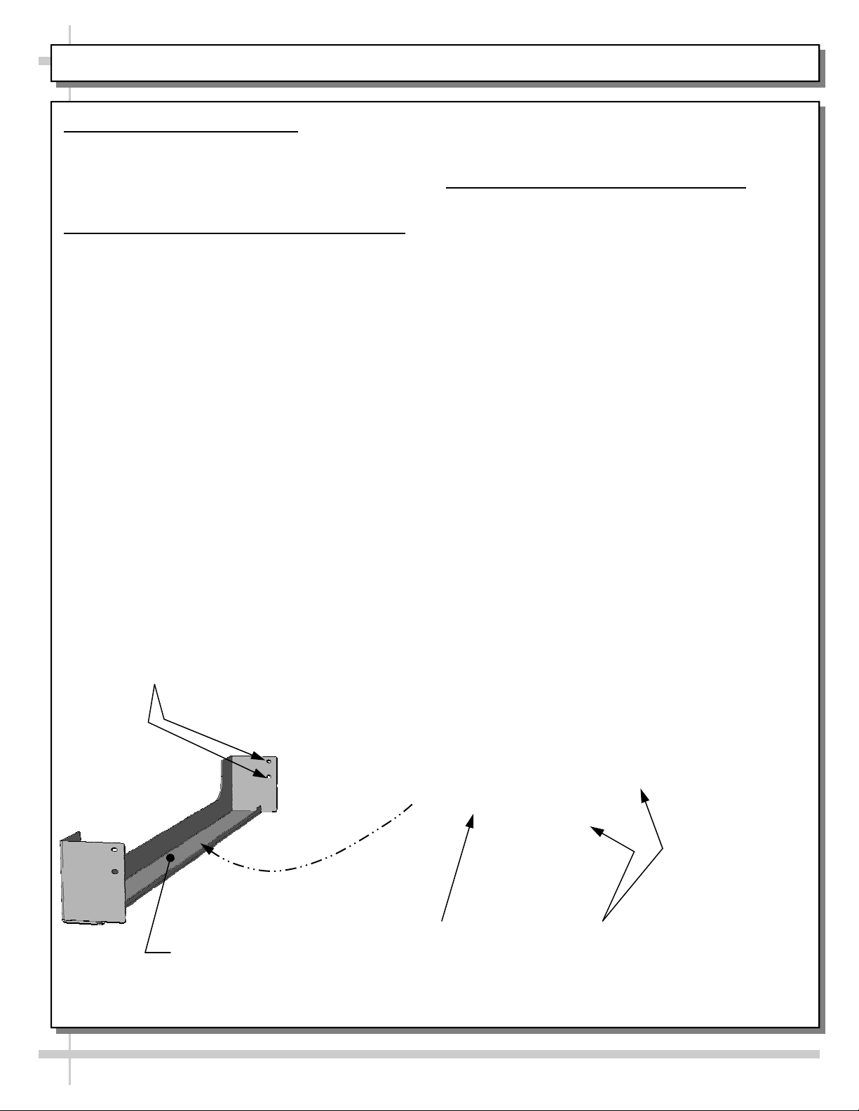
1. Shipping Bracket Purpose
Shipping brackets are designed to secure
condenser package during shipment.
See illustration below.
2. Shipping Bracket Removal and Disposal
Shipping bracket is secured by two (2)
screws at each end.
Remove all four (4 screws) from bracket.
Remove bracket from case.
Either discard or recycle.
See illustration below.
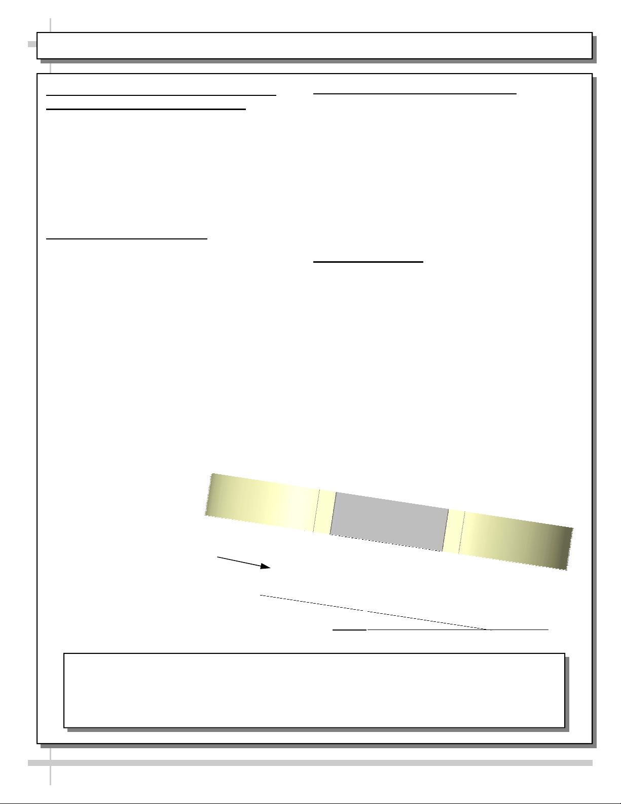
3. Shipping Brace For In-Line Casters
A shipping brace is on the condenser coil side of
case.
It is to be removed AFTER the case is in position.
Brace may be removed via four (4) screws.
Discard/recycle after removal.
A view of the brace is shown in “removed”
position below for illustrative purposes only.
Shipping Brace
Attachment Holes (Typ.)
Enlarged View of
Shipping Brace For
In-Line Casters
(Shown Removed)
Enlarged View of
Shipping Brace For
In-Line Casters
(Shown Attached)
Shipping Brackets
(Typ.)
5
KICK PANEL REMOVAL / REMOVAL OF CASE FROM PALLET / POSITIONING UNIT
1. Note: Kick Panels Are NOT To Be On
Case During Removal From Pallet!
Kick panels can easily buckle or bend while
removing from pallet.
If kick panels are on case, remove by lifting
up and off. No screw removal is required to
remove kick panels.
After unit is in position, kick panels are to be
placed on case.
2. Remove Unit From Pallet
For your safety, the equipment is furnished
with a properly grounded cord connector. Do
not attempt to defeat the grounded connector.
Fork Lift
To lift case up for lift-truck forks to slide into
position, use J-Bar lift tab.
Make certain case is
well-supported on lift
truck. Move into
position.
3. J-Bar or Dolly Only (No Fork Lift)
Slide case to edge of pallet.
With several people in position, carefully slide
frame support rail to edge of pallet.
With several people in position, slide case several
more inches (off pallet) and lower rear frame
support to floor.
Once the rear frame support rail rests on the floor,
have several people supporting front of case while
pallet is slid out from under case.
After case is off pallet, several employees may be
required to slide into position.
4. Positioning Unit
Place unit into desired location before leveling.
See next page for leveling specifics.
View of Unit WITHOUT
Kick Panels Attached
Note! Kick Panels Are NOT To Be On
Case During Removal From Pallet!
6

LEVELING UNIT / SHIMMING FRAME SUPPORT RAILS (REMOTE UNITS ONLY)
Leveling Unit / Shimming Frame Support
Rails (Remote Units Only)
Case must be leveled to assure proper operation.
Frame support rails may be shimmed to assure
that it is level.
Shims will be provided with such cases.
Illustration below shows case with frame support
rails.
Note: After case has been properly shimmed,
attach panels. No screws are required.
See next page for caster/leveler system
(self-contained units only)
Frame
Support Rail
7
Illustration Shown May Not Exactly
Reflect Every Feature or Option of
Your Particular Model

CASTER SYSTEM (OPTIONAL) / LEVELERS (SELF-CONTAINED UNITS ONLY)
1. Caster System (Optional)
Certain cases have a caster system that allows
case to be slid in and out of position.
See illustration below.
2. Lower Levelers
After case is in position, lower levelers until the
case is raised off its casters.
Level case (by turning levelers as necessary).
--- Model FSI656R Shown Below ---
3. Raise Levelers
Levelers may be raised to allow case to be slid to
new location.
Simply raise levelers ABOVE casters and slide
case to new location.
Then, lower levelers (as instructed in step #2).
Illustration Shown May Not
Exactly Reflect Every
Feature or Option of Your
Particular Model
Levelers (Typ.)
Caster System (Typ.)
8
CEILING ORIGINATED ELECTRICAL & REFRIGERATION LINES / KNOCKOUT REMOVAL / SEALING
1. Merchandiser Versatility
Structural Concepts cases can accompany
either floor or ceiling originated electrical and/or
refrigeration lines.
This page shows how ceiling originated lines
are routed into case.
2. Ceiling Routed Electrical/Refrigeration. Lines
A center pass-through protective plate is
mounted at top of case over two (2) PVC
center pass-throughs.
If electrical/refrigeration lines are ceiling
originated, remove plate knockouts.
Electrical and/or refrigeration lines may then be
dropped through PVC center pass-throughs.
Caution! If ceiling originated lines are used, you
MUST seal both upper and lower PVC passthroughs (at entrance points) with expandable
foam sealant to prevent condensation in case.
3. Plate Removal
Note: Though not required, protective plate can be
removed from merchandiser via four (4) screws.
4. Case Underside
Depending upon your model, see either
REFRIGERATION FUNDAMENTALS: REMOTE
DRAIN LAYOUT or REFRIGERATION
FUNDAMENTALS: SELF-CONTAINED DRAIN
LAYOUT section in this manual for location of
center pass-throughs at underside of case.
Center Pass-Through
Protective Plate Mounted
on Merchandiser
Caution! If ceiling
originated lines are used,
you MUST seal both upper
and lower PVC pass-
throughs (at entrance
points) with expandable
foam sealant to prevent
condensation in case.
Center Pass-Through
Protective Plate Shown After
Removal of Knock-Outs
9
REMOTE CASES: REFRIGERATION LINE FIELD CONNECTION
1. Refrigeration Line Field Connection
Warning! Turn power off and/or disconnect
power before providing maintenance and
service to unit.
Assembly/disassembly/servicing is to be
performed by licensed refrigeration
contractor.
2. Refrigeration Lines at Underside
Underside refrigeration lines are standard.
Refrigeration lines are ALWAYS at rear of case.
See photograph immediately below for illustration.
Field-Connect
Refrigeration Lines Are Through
Underside PVC Tubes
Illustration Shown May
Not Exactly Reflect
Every Feature or Option
of Your Particular Case
--- View of Remote Case With Underside Refrigeration Lines ---
10
REMOTE CASES: CONDENSATE PUMP LOCATION AND PURPOSE
1. Condensate Pump Location
Warning! Turn power off and/or disconnect
power before providing maintenance and
service to unit.
Assembly/disassembly/servicing to be
performed by licensed refrigeration
contractor.
Condensate pump is located just behind
ballast box (as shown in illustration below).
Ballast
Box
2. Condensate Pump Purpose
Condensate pump is to be used when no floor
drain is available.
Condensate pump transfers condensation
from lower section of case through top of
case and out.
Condensate
Pump Is To Be
Used When No
Floor Drain Is
Available
11
 Loading...