

Page 1
READ AND SAVE THESE INSTRUCTIONS
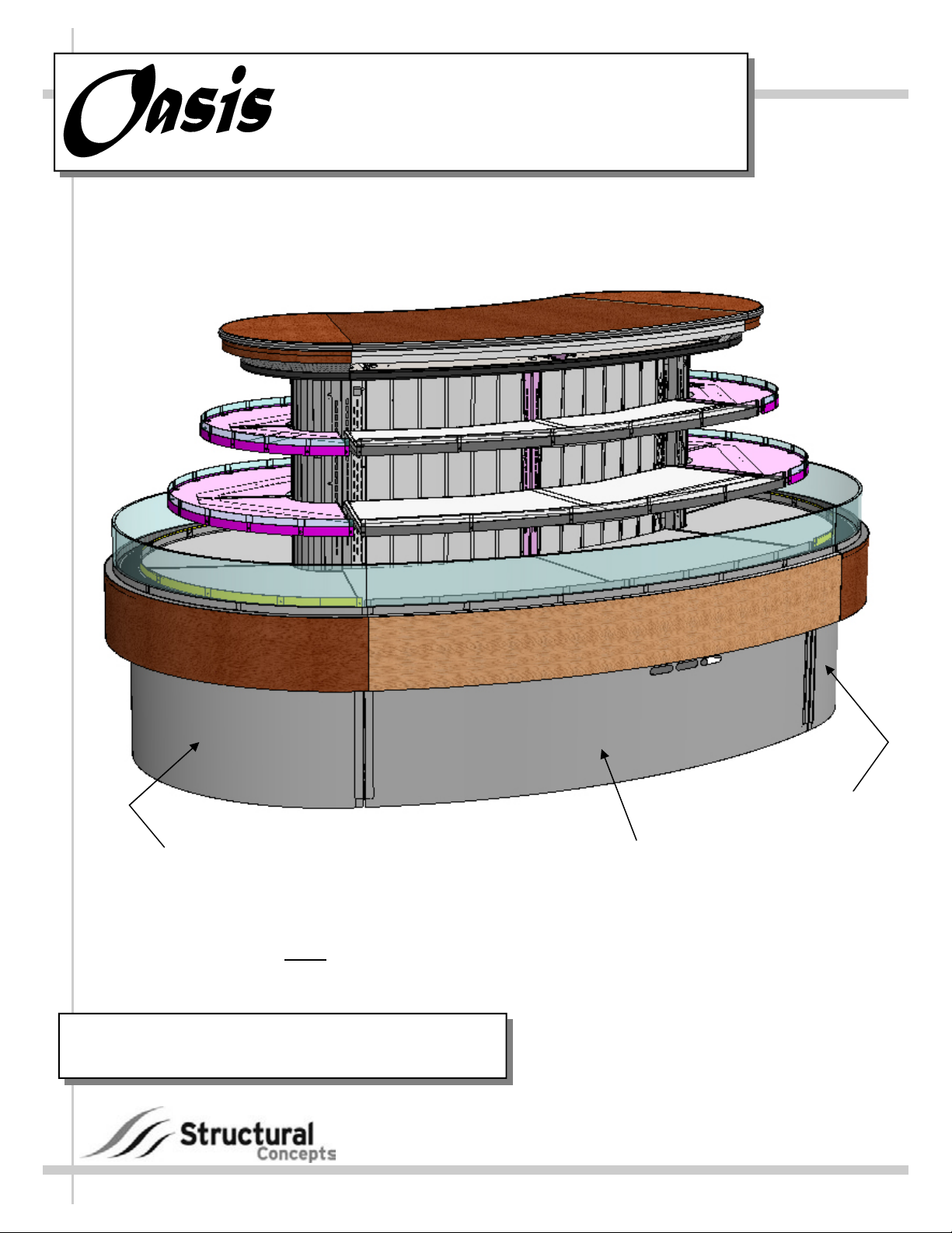
INSTALLATION &
SELF-SERVICE REFRIGERATED SERPENTINE ISLAND MERCHANDISER
OPERATING MANUAL
PN 63224
FSE65R
Case Front View
(For Purposes of This Operating Manual)
Note
: Model FSI105R is Full Assembly of
(2) FSE65R and (1) FSC65R
Model FSI105R…...…………120”L x 72”D x 69 3/4”H*
*With levelers extended 1 5/8” below base frame
888 E. Porter Road · Muskegon, MI 49441 Phone: 231.798.8888 Fax: 231.798.4960 www.structuralconcepts.com
I:\Oper Manual\Oasis\FSI105R_FSE65R_FSC65R_63224.pub
FSE65R
FSC65R
Rev B Date: 11.29.2010
Page 2
TABLE OF CONTENTS
OVERVIEW AND WARNINGS ….…………………..……………………..…………...………….....…..
REMOVAL FROM SKID / POSITIONING UNIT ….……...…………………………………..………….
BOLTING AND CAULKING UNITS TOGETHER [FOR CASES SHIPPED SEPARATELY]……...
ADJUSTING LEVELERS ………………………………………………………… ……………………….
FIELD WIRING ACCESS / FRONT TOE-KICK REMOVAL ……………..………...………………….
POWER-UP CHECK / LIGHTS …………………………………………………………………………...
MAINTENANCE FUNDAMENTALS - SHELF ASS’Y REMOVAL / LIGHT FIXTURES .…………..
MAINTENANCE FUNDAMENTALS - HONEYCOMB AIR DIFFUSERS ………………………...…..
REFRIGERATION FUNDAMENTALS / DRAIN LAYOUT ...………………..…………………..……..
EVAPORATOR PAN ACCESS: REMOTE UNITS WITH EVAPORATOR PANS ONLY ………….
CLEANING SCHEDULE - TO BE PERFORMED BY STORE PERSONNEL .…………………..…..
TROUBLESHOOTING - GENERAL ISSUES ……………………..………………………………… ….
PREVENTIVE MAINTENANCE (TO BE PERFORMED BY TRAINED SERVICE PROVIDER) …..
SERIAL LABEL LOCATION & INFORMATION LISTED / TECH INFO & SERVICE…….………....
TECHNICAL SERVICE CONTACT INFORMATION & WARRANTY INFORMATION ..…………...
3
4
5
6
7
8
9
10
11
12
13
14-15
16
17
18
2
Page 3
OVERVIEW AND WARNINGS
OVERVIEW
These Structural Concepts Oasis® service cases are designed to merchandise packaged products at
5°C / 41°F or less product temperatures.
These cases should be installed and operated according to this operating manual’s instructions to
insure proper performance. Improper use will void warranty.
This unit is designed for the display of products in ambient store conditions where temperatures and
humidity are maintained within a specific range.
For NSF® Type 1 Conditions (most cases): ambient conditions are to be at 55% max. humidity / 75°F.
For NSF® Type 2 Conditions: ambient conditions are to be at 60% maximum humidity / 80°F.
If unsure if your case is Type 1 or Type 2, contact Structural Concepts Technical Service (see
Technical Service section in this manual for phone number).
Caution: Do not allow air conditioning, electric fans, open doors or windows to create air currents
around display case as this may detrimentally affect proper case temperatures and operation.
ATTENTION INSTALLER
This equipment must be installed in compliance with all
applicable NEC, federal, state and local plumbing codes.
WARNING
ELECTRICAL
HAZARD
WARNING
KEEP HANDS
CLEAR
CAUTION
WARNING
Risk of electric shock.
Disconnect power before servicing unit
WARNING
Hazardous moving parts. Do not operate unit with covers removed.
Fan blades may be exposed when deck panel is removed.
Disconnect power before removing deck panel.
CAUTION
Lamps have been treated to resist breakage
and must be replaced with similarly treated lamps.
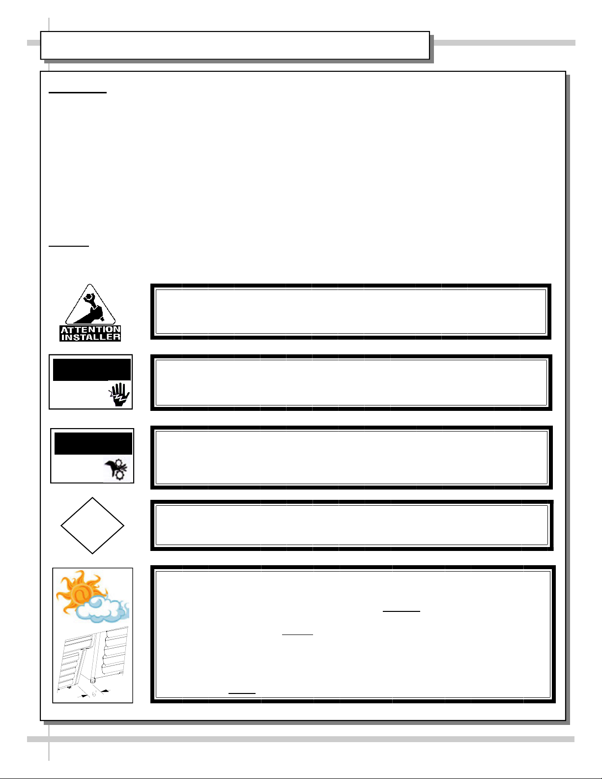
WARNING! ADVERSE CONDITIONS / SPACING ISSUES
Performance issues caused by adverse conditions are NOT covered by warranty.
End panels must be tightly joined or kept at least 6-inches
away from any structure to
prevent condensation.
Unit must be kept at least 15-feet
from exterior doors, overhead HVAC vents or any
air curtain disruption to maintain proper temperatures.
Unit must not be exposed to direct sunlight or any heat source (ovens, fryers, etc.).
Tile floors, low ceilings or small rooms will increase noise level. Whisper Cool
compressor blanket [or remote unit] may resolve noise level issues.
Keep at least 8-inch
clearance above unit for air discharge (self-contained units only).
3
Page 4
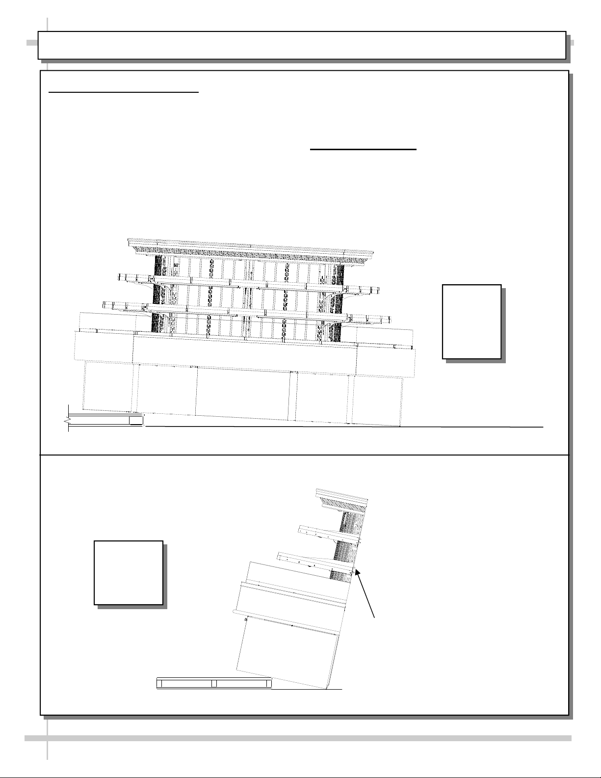
REMOVAL FROM SKID / POSITIONING UNIT
1. Remove Unit From Skid
For your safety, the equipment is furnished with
a properly grounded cord connector. Do not
attempt to defeat the grounded connector.
Illustrations below show:
> Fully assembled case being removed
from skid.
> Disassembled case being removed
from skid.
Remove case from skid and place in proper
location.
Plug cord into certified electrical outlet with a
ground.
2. Positioning Unit
Place unit into desired location before leveling.
See next page for specifics about leveling.
View of
Fully
Assembled
Case Being
Removed
From Skid
View of
Disassembled
Case Being
Removed
From Skid
Provide
support
while
removing
from
skid
4
Page 5
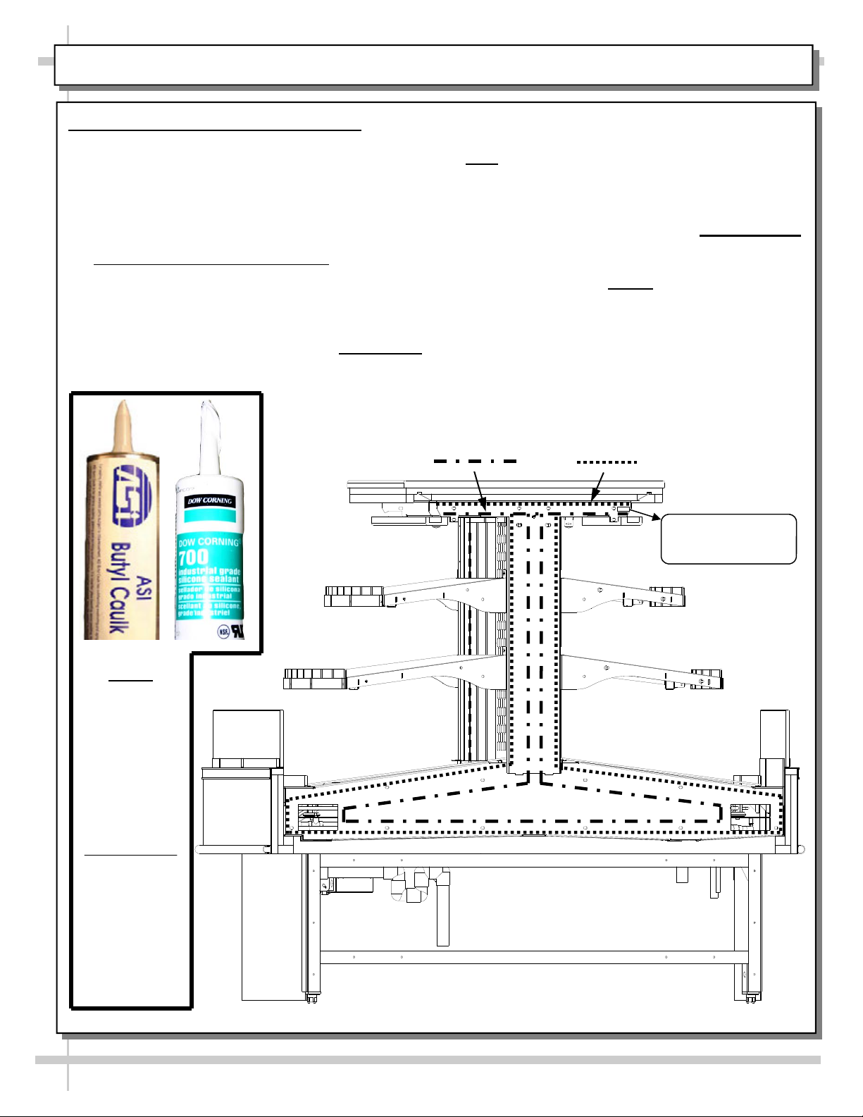
BOLTING AND CAULKING UNITS TOGETHER [FOR CASES SHIPPED SEPARATELY]
Bolting and Caulking Units Together
Follow these steps to assure a secure, level lineup.
A. Begin lineup leveling from highest point of floor.
B. After the ’first’ case is level, apply industrial
grade butyl caulk on non-visible areas. You
may use industrial grade silicone sealant on
visible areas.
C. Form Two (2) Caulk/Sealant Lines
and Refrigeration). See illustration below for
outline of caulk/sealant lines.
D. Line up adjoining case (same model) bolt-hole
to bolt-hole to this case.
E. Cases come from factory with bolts pre-inserted
in holes and labels next to adjoinment locations.
: (Sanitation
F. Labels read, “USE THIS HOLE FOR LINE-UP
STEP #1”, “2”, “3”, etc. See sample label below.
G. Note
H. Front of cases MUST be flush with each other.
I. Using SCC-supplied nuts & bolts, lightly tighten
J. After the cases are bolted together, level the
K. After all lined-up cases are level, seal all seams
Sanitation
: You may need to remove decking to
access lower bolt holes.
After leveling, cases are to be same height.
each of the bolts in a cross-wise pattern. Work
your way around the pattern, tightening more
firmly at each pass. Do not
bolt and then start on the next.
case to be adjoined. Repeat this process for
each adjoining case.
with industrial grade silicone sealant.
Bead
Refrigeration
Bead
firmly tighten one
Note
Butyl
is to be
used
on
non-visible
areas.
Silicone
is to be
used on
USE THIS HOLE FOR
LINE-UP STEP #2
visible
areas.
Above illustration may not exactly reflect every
feature or option of your particular case
5
Page 6
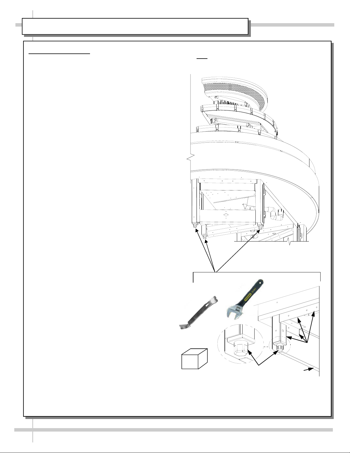
ADJUSTING LEVELERS
Adjusting Levelers
After case is in position, adjust case so it is level
and plumb (see illustration at right).
You may need to remove front and/or rear toe-
kick to access levelers.
Use adjustable wrench (and possibly a pry bar) to
adjust leveler.
Do not use pry bar on toe-kick (it may buckle).
Do not use pry bar on end panel (it may chip).
Use pry bar ONLY on base frame to avoid
damaging case.
Use a block to reach base frames with pry bar.
See illustrations at right.
Note: Below illustration may not exactly reflect every
feature or option of your particular case
Pry Bar
Block
Adjustable
Wrench
Base
Frame
6
Leveler
Toe-Kick
Page 7

FIELD WIRING ACCESS / FRONT TOE-KICK REMOVAL
Field Wiring
Access to Field Wiring Box to be
accomplished by licensed electrical
contractor.
To access field wiring box, remove front toe-
kick by grasping firmly and pulling outward.
Front Toe-Kick Removal
Each end of toe-kick will release from toe-kick
retaining sheaths holding them in place.
When returning to case, simply insert each
end of toe-kick into retaining sheaths.
Toe-kick will rest on floor while being securely
held at each end by the retaining sheaths.
Ballast Box /
Terminal Strip
Field Wiring
Box
Electrical Box
For FSC65R
[Center Section]
Ballast Box Access
Warning! Turn power off and/or disconnect
power before providing maintenance and
service to unit.
Assembly or disassembly and servicing to be
accomplished by licensed electrical contractor.
To access, remove toe-kick nearest desired ballast
box. No screw removal required.
Enlarged View of
4 x 4
Evaporator
Pan
Assembly
Toe-Kick Retaining
Sheath [One at
Each End]
Ballast Box For
FSE65R
[Front-Left End]
Drain Lines are Shipped
Loose [To be
Attached in Field]
7
Refrigeration
Lines
Ballast Box For
FSE65R
[Front-Right End]
Page 8

POWER-UP CHECK / LIGHTS
1. Power-Up Check
After power has been supplied, evaporator coil fans and compressor motor will be operational.
To verify fans are operational, lift up deck pans; check to see that the coil fans are all functioning properly.
Illustration below is of end cap.
2. Lights
Light switches are located inside on the plenums (see illustration below).
Note: There are four (4) Light Switches. Each light switch controls a separate section of the display case
(sides and end caps).
Note: All lights should come on at the same time.
First time lighting may require a short warm up period for the bulbs.
Slightly dim or a flickering of new
bulbs is normal.
If lights do not turn on, check all of
the plug connections.
See next page for additional
information on light fixtures.
View of evaporator
coil fans, TXV valves
and drain after decks
have been removed.
ON
OFF
Rocker Switch
Enlarged View
Note: There
are four (4)
Light
Switches.
Each light
switch
controls a
separate
section of the
display case
(sides and end
caps).
8
Page 9

MAINTENANCE FUNDAMENTALS - SHELF ASS’Y REMOVAL / LIGHT FIXTURES
Shelf Assembly Removal
Shelving removable and adjustable on 1”
centers.
Lift shelf up & out OR lift shelf up and tip
downward from uprights.
See illustration at right.
Light Fixtures (Florescent Bulbs)
See previous location for light switch location.
Light fixtures are located in the shelves front
and sides and at the top inside of case. See
photo below.
Removal of lamps:
Grasp lamp firmly and carefully pull downward
and out from socket.
See photos at mid-right.
Installation of lamp:
Align pins with slot.
Insert pins into socket and push upward into
place.
See photos at mid-right.
View of shelf position.
: Wires have
Note
sufficient slack to allow
for shelf adjustment.
Photos of
Fluorescent
Bulb
Removal
Note: Lights bulbs
and fixtures
Note: Lights bulbs
and fixtures
Note: Lights bulbs
and fixtures
Note: Illustration at
left may not
exactly reflect
every feature or
option of your
particular case
9
Page 10

MAINTENANCE FUNDAMENTALS - HONEYCOMB AIR DIFFUSERS
Preventive maintenance should be performed
every 30 days unless conditions warrant a more
frequent replacement cycle.
Honeycomb Air Diffuser Removal
A. Wedge non-metallic device of suitable strength (such
as a ballpoint pen) between honeycomb and end panel.
Caution
prevents condensation on the lamp assembly).
B. Apply pressure to collapse the honeycomb to allow it
to be pulled out of honeycomb retainer.
C. Pry downward and away from honeycomb retainer.
Clean honeycomb with warm water and soap solution.
Submerse if necessary. Use brush to dislodge stubborn
or sticky residue. Dry by using vacuum’s ‘blow mode’.
Honeycomb Air Diffuser Installation
D. Squeeze honeycomb into the honeycomb retainer.
E. Carefully slide honeycomb into place.
F. Adjust honeycomb so that it fits flat
It must not be wavy or out of position.
Note: For honeycomb air diffusers in other locations,
these same general instructions apply.
! Use care not to dislodge the heating wire (that
against retainer.
Honeycomb
Air Diffuser
(Around
Entire Unit)
A
F
B
D
C
E
10
Page 11

REFRIGERATION FUNDAMENTALS: DRAIN LAYOUT
Refrigeration Line Access, Connections & Servicing to be accomplished by licensed refrigeration
contractor only.
Illustration below shows location of refrigeration lines for remote connection.
Four (4) drains accessible from top of unit by lifting up decking.
See POWER-UP CHECK / LIGHTS section in this manual for under decking drain illustration.
See next page, EVAPORATOR PAN ACCESS: REMOTE UNITS WITH EVAPORATOR PANS ONLY
for specifics on access, removal and replacement.
Case Front
Drain
Evaporator
Pan
Drain Lines are
Shipped Loose
[To be
Attached in Field]
Front-Left
End Drain
Drain Line [To be
Attached in Field]
Case Rear
Drain
11
Refrigeration
Lines
Drain Line [To be
Attached in Field]
Front-Right
End Drain
Page 12

EVAPORATOR PAN ACCESS: REMOTE UNITS WITH EVAPORATOR PANS ONLY
Evaporator Pan Access / Removal / Replacement
Warning! Disconnect power before providing
maintenance and service to unit.
To access, remove the front panel. Simply lift
panel out from toe-kick retaining sheaths (no
screw removal is required).
To service or clean, unplug the evaporator pan
Electrical Outlet
For Evap. Pan
from its outlet.
Remove the screws holding the evaporator
pan foot to the evaporator pan support (see
illustration below).
Carefully slide the evaporator pan off from the
evaporator pan support.
When done servicing or cleaning, return and
reconnect in reverse order it was removed.
Fans For
Evaporator Pan
Drain
[Case Front]
Drain
P-Trap
Evaporator
Pan Drain
Evaporator
Pan
Evaporator Pan Support
12
Page 13

CLEANING SCHEDULE - TO BE PERFORMED BY STORE PERSONNEL
AREA FREQ. INSTRUCTIONS
Exterior Weekly
Weekly
Monthly
Interior Weekly
Monthly
Front and Side Panels, Wood, Laminate and Painted Surfaces: Clean with
mild soap and water solution and a non-abrasive soft cloth .
Acrylic: Clean with warm water, mild soap solution and soft cloth; acrylic
cleaning solutions are also available. Caution! Never use ammonia-based
cleaners on acrylic. Incorrect cleaning agents or abrasive cleaning cloths cause
surface to ‘cloud’ over time.
Under Case Cleaning
: Remove front toe-kick (or rear grille). Vacuum under
case to remove all dust and dirt. Replace front toe-kick (or rear grille) when
complete.
Decks: Wipe off decks with moist cloth dipped in mild soap and water solution.
Tub and Drain: Keep clean and free of debris which could clog tub and drain.
To access drain area, remove the deck and fan shroud.
Vacuum tub under deck.
Run hose into drain to flush out debris. Carefully hose out the tub.
Caution! Avoid splattering water over the case and surrounding areas!
See POWER-UP CHECK / LIGHTS section in this manual for under decking
drain illustration.
Monthly
Air Return Grille and Fan Shroud Area
: 1) Turn off power. 2) Remove decks
from case. 3) Clean with moist cloth.
Monthly
Honeycomb Air Diffuser
: See MAINTENANCE FUNDAMENTALS -
HONEYCOMB AIR DIFFUSERS section in this manual for cleaning instructions.
Quarterly
Evaporator Pan
: Disconnect plug from receptacle box. Remove mounting
screw(s) from base. Use de-scaling solution (such as CLR®) to prevent
calcium, lime and rust from forming to clean the pan. Rinse thoroughly; do not
submerse in water. Reconnect plug into receptacle box.
13
Page 14

TROUBLESHOOTING - GENERAL ISSUES (PAGE 1 of 2)
CONDITION TROUBLESHOOTING
Water Is On The Floor
Caution! Water on flooring can cause much damage! Until cause is
determined (and repaired), follow these procedures:
Use wet-dry vacuum (or mop & bucket) to remove standing water.
Use ‘catch pans’ for water to drain into. Swap out regularly until
case has completely drained.
Check that the drain trap is free of debris.
Check store conditions. To prevent condensation in NSF® Type 1
environments, maximum conditions are to be 55% humidity / 75°
Fahrenheit. For NSF® Type 2, maximum conditions are to be 60%
humidity / 80° Fahrenheit. See serial label (at case rear near main
power switch) for NSF® Type of your case.
14
Page 15

TROUBLESHOOTING - GENERAL ISSUES (PAGE 2 of 2)
CONDITION TROUBLESHOOTING
Fan Emits Excessive Noise
Fans Are Not Working
Check that the case is aligned, level and plumb.
Check evaporator fan for cleanliness.
Unplug fan motors; check motor shaft for excessive bearing
wear.
Check that fan motors are securely mounted in brackets.
Verify that fan blades are securely mounted to fan motor.
Check that nothing is preventing blade rotation.
Check that the fan shroud is properly secured.
Check that the MAIN power switch (if present) is on.
Otherwise, check that power is provided to case.
Warning! servicing to be accomplished by licensed
electrical contractor.
Check that fans are plugged in to fan shroud.
Check for foreign material obstructing fan performance.
Check that fan blades freely rotate within fan shrouds.
Check that power is going to fans.
System Is Not Operating
Check that fan wiring is connected on terminal blocks.
Check that the utility power is provided to case.
Check circuit breaker box for tripped circuits.
Case Is Not Holding Temperature
If a large amount of warm product was added to the case, it will
take time for the temperature to adjust.
Check that the case is not in the sun or near a heat or air
conditioning vent.
If case is located near outside doors, temperature fluctuation
can hinder unit’s ability to maintain temperature.
Case Lights Are Not Working
Check that light switch is in the ON position.
Check for burned out bulbs. Turn lights off & replace.
Clean dirt and dust from the bulbs to prevent flickering.
Check to insure voltage at ballasts. If voltage is entering but not
exiting the ballast, ballast is faulty.
Check that ALL lights are plugged in and receptacles capped.
15
Page 16

PREVENTIVE MAINTENANCE (TO BE PERFORMED BY TRAINED SERVICE PROVIDER)
WARNING! TURN OFF CASE BEFORE PERFORMING PREVENTIVE MAINTENANCE!
PREVENTIVE
FREQUENCY INSTRUCTIONS
MAINTENANCE
Case Interior Quarterly
Evaporator Pan: Disconnect plug from receptacle box. Remove
mounting screws from base. Use de-scaling solution (such as
CLR®) to prevent calcium, lime and rust from forming to clean the
pan. Rinse thoroughly; do not submerse in water. Reconnect plug
into receptacle box.
Case Interior Quarterly Tub, Coil, Drain, Evaporator Fan Blades, Motors, Brackets:
Disconnect power from the case before cleaning the Tub, Coil, Fan,
Motor and Drain Area!
Remove Decking, Sub-Deck and Fan Shroud.
Use vacuum to clean Evaporator Coils.
Clean Tub, Coil and Drain with warm water, clean cloth, brush
and mild soap solution.
Remove any debris that may clog drain.
Clean Fan Blades, Motors and Brackets by wiping down with
moist cloth.
16
Page 17

SERIAL LABEL LOCATION & INFORMATION LISTED / TECH INFO & SERVICE
Serial Label Location & Information Listed / Technical Information & Service
Serial labels are located near the electrical access on your case.
Serial labels contain electrical, temperature & refrigeration information, as well as regulatory
standards to which the case conforms.
For additional technical information and service, see the TECHNICAL SERVICE page in this
manual for instructions on contacting Structural Concepts’ Technical Service Department.
See images below for samples of both refrigerated and non-refrigerated serial labels.
S
A
M
P
L
E
ON
L
Y
Y
L
ON
LE
MP
A
S
----- Sample Serial Label For Refrigerated Case -----
Y
NL
O
SA
PLE
M
----- Sample Serial Label For Non-Refrigerated Case -----
888 E. Porter Road · Muskegon, MI 49441 Phone: 231.798.8888 Fax: 231.798.4960 www.structuralconcepts.com
17
Page 18

TECHNICAL SERVICE CONTACT INFORMATION & WARRANTY I NFORMATION
STRUCTURAL CONCEPTS CORPORATION TECHNICAL SERVICE
PHONE NUMBER: 1.800.433.9489 or For Your Master Service Agent See
WWW.STRUCTURALCONCEPTS.COM/Contact/Master_Service_Agents.asp
WARRANTY INFORMATION
(Note: Standard Limited Warranty can be found at www.Structuralconcepts.com)
All sales by Structural Concepts Corporation (SCC) are subject to the following limited warranty. “Goods” refers to the product or products being sold by SCC.
Warranty Scope: Warranty is for equipment sold in the United States, Canada, Mexico and Puerto Rico. Equipment sold elsewhere may carry modified warranty.
Warranty; Remedies; Limitations. SCC warrants that if any Goods are found by an authorized representative of SCC not to be of good material or workmanship within one
year of the date of shipments SCC will, at its option after inspection by an authorized representative, replace any defective Good or pay the reasonable cost of replacement
for any such defective Goods, provided that written notice of the defect is given to SCC within 30 days of the appearance of such defect. If notice is not given within such
period, any claim for breach of warranty shall be conclusively deemed to have been waived and SCC shall not be liable under this warranty. If SCC is unable to repair or
replace the defective Goods, SCC shall issue a credit to the Purchaser for all or part of the purchase price, as SCC shall determine. The replacement or payment in the
manner described above shall be the sole and exclusive remedy of Purchaser for a breach of this warranty. If any Goods are defective or fail to conform to this warranty,
SCC will furnish instructions for their disposition. No Goods shall be returned to SCC without its prior consent.
SCC’s liability for any defect in the Goods shall not exceed the purchase price of the Goods. SCC SHALL HAVE NO LIABILITY TO PURCHASE FOR CONSEQUENTIAL
DAMAGES OF ANY KIND WHATSOEVER, INCLUDING, BUT NOT LIMITED TO, PERSONAL INJURY, PROPERTY DAMAGE, LOST PROFITS, OR OTHER ECONOMIC
INJURY DUE TO ANY DEFECT IN THE GOODS OR ANY BREACH OF SCC, SCC SHALL NOT BE LIABLE TO THE PURCHASER IN TORT FOR ANY NEGLIGENT DESIGN OR MANUFACTURE OF THE GOODS, OR FOR THE OMISSION OF ANY WARNING THEREFROM.
SCC shall have no obligation or liability under this warranty for claims arising from any other party’s (including Purchaser’s) negligence or misuse of the Goods or
environmental conditions. This warranty does not apply to any claim or damage arising for or cause by improper storage, handling, installation, maintenance, or from fire,
flood, accidents, structural defects, building settlement or movement, acts of God, or other causes beyond SCC’s control.
Except as expressly stated herein, SCC makes no warranty, express, implied, statutory or otherwise as to any parts or goods not manufactured by SCC. SCC shall warrant
such parts or Goods only (I) against such defects, (II) for such periods of time, and (III) with such remedies, as are expressly warranted by the manufacturer of such parts of
Goods. Notwithstanding the foregoing, any warranty with respect to such parts of Goods and any remedies available as a result of a breach thereof shall be subject to all of
the procedures, limitations, and exclusions set forth herein.
THE WARRANTIES HEREIN ARE IN LIEU OF ALL WARRANTIES, EXPRESS, IMPLIED, STATUTORY, OR OTHERWISE. IN PARTICULAR, SCC MAKES NO
WARRANTY OF MERCHANTABILITY OR FITNESS FOR A PARTICULAR PURPOSE.
No representative, agent or dealer of SCC has authority to modify, expand, or extend this Warranty, to waive any of the limitations or exclusions, or to make any different or
additional warranties with respect to Goods.
Period of Limitations. No claim, suit or other proceeding may be brought by Purchaser for any breach of the foregoing warranty or this Agreement by SCC or in any way
arising out of this Agreement or relating to the Goods after one year from the date of the breach. In the interpretation of this limitation on action for a breach by SCC, it is
expressly agreed that there are no warranties of future performance of the goods that would extend that period of limitation herein contained for bringing an action.
Indemnifications. Purchaser agrees to indemnify, hold harmless, and defend SCC if so requested, from any and all liabilities, as defined herein, suffered, or incurred by SCC
as a result of, or in connection with, any act, omission, or use of the Goods by Purchaser, its employees or customers, or any breach of this Agreement by Purchaser.
Liabilities shall include all costs, claims, damages, judgments, and expenses (including reasonable attorney fees and costs).
Remedies of SCC. SCC’s rights and remedies shall be cumulative and may be exercised from time to time. In a proceeding or action relating to the breach of this Agreement
by Purchaser, Purchaser shall reimburse SCC for reasonable costs and attorney’s fees incurred by SCC. No waiver by SCC of any breach of Purchaser shall be effective
unless in writing nor operate as a waiver of any other breach of the same term thereafter. SCC shall not lose any right because it has not exercised it in the past.
Applicable Law. This Agreement is made in Michigan and shall be governed by and interpreted according to Michigan law. Any lawsuit arising out of this Agreement or the
Goods may be handled by a federal or state court whose district includes Muskegon County, Michigan, and Purchaser consents that such court shall have personal
jurisdiction over Purchaser.
Miscellaneous. If any provision of this Agreement is found to be invalid or unenforceable under any law, the provision shall be ineffective to that extent and for the duration of
the illegality, but the remaining provisions shall be unaffected. Purchaser shall not assign any of its rights nor delegate any of this obligations under this Agreement without
prior written of SCC. This Agreement shall be binding upon and inure to the benefit of SCC and Purchaser and each of their legal representatives, successors and assigns.
SCC warrants its products to be free of defects in materials and workmanship under normal use and service for a period of one (1) year from the date of delivery.
This warranty is extended only to the original purchaser for use of the Goods. It does not cover normal wear parts such as plastic tongs, tong holders, tong cables, bag
holders, or acrylic dividers.
General Conditions. All service labor and/or parts charges are subject to approval by SCC. Contact the Customer Service Department in writing or call 231-798-8888.
All claims must contain the following information: (1) model & serial code number of equipment; (2) the date and place of installation; (3) the name and address of the agency
which performed the installation; (4) the date of the equipment failure; and (5) a complete description of the equipment failure and all circumstances relating to that failure.
Once the claim has been determined to be a true warranty claim by SCC’s Customer Service Department, the following procedure will be taken: (1) replacement parts will be
sent at no charge from SCC on a freight prepaid basis; (2) reimbursement for service labor will be paid if the following conditions have been met— (a) prior approval of service agency was awarded from the Customer Service Department; and (b) an itemized statement of all labor charges incurred is received by the Customer Service Department. The cost of the service labor reimbursement will be based on straight time rates and reasonable time for the repair of the defect.
If problems occur with any compressor, notify SCC’s Customer Service Department immediately. Any attempt to repair or alter the unit without prior consent from the
Customer Service Department will render any warranty claim null and void. This warranty and protection plan does not apply to any condensing unit or any part thereof which
has been subject to accident, negligence, misuse, or abuse, or which has not been operated in accordance with the manufacturer’s recommendations or if the serial number
of the unit has been altered, defaced, or removed.
Limit of Liability. The limit of liability of SCC toward the exchange cost of the original condensing unit, F.O.B. SCC, Norton Shores, MI, of each motor-compressor assembly
replaced during the warranty shall not exceed manufacturer's current established wholesaler’s exchange price and in no case shall the labor of removing or replacing the
motor-compressor or parts thereof be the responsibility of SCC.
18
 Loading...