


E6581429
Safety precautions
Introduction
Contents
I
II
Instruction Manual
Totally enclosed box type Inverter
TOSVERTTM VF-PS1
Read first
Connection of equipment
Operations
Searching and setting parameters
Monitoring the operation status
List of function key functions
Measures to satisfy the standards
Selection of peripheral devices
Table of parameters
Specifications
1
2
3
4
5
6
7
8
9
10
NOTICE
1.Make sure that this instruction manual is delivered to the end user of the inverter unit.
2.This manual gives supplementary information of some items referred in the instruction manual E6581386 supplied with the product. Read this manual and E6581386 before installing or operating the inverter unit, and store them in a safe place for reference.
|
E6581429 |
||
|
|
|
|
I. Safety precautions |
|
|
I |
|
|
|
|
|
|
|
|
Thoroughly familiarize yourself with the symbols and indications shown in “I. Safety Precautions,” of the instruction manual E6581386 and below, and then continue to read manuals. Make sure that you observe all cautions given.
Q Transportation & installation
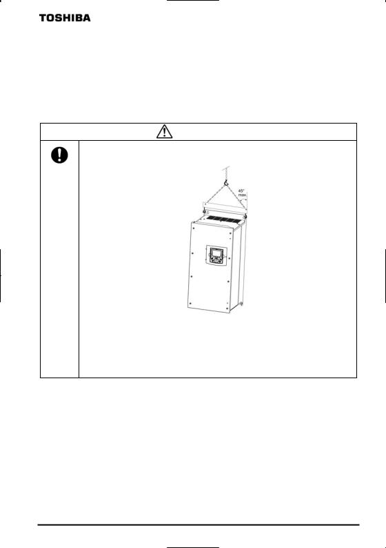
Caution
•Handle the inverter unit with a crane.
Lifting heavy inverters can cause injury to persons.
Taking care of safety for users, handle carefully in order not to damage the inverter.
Carefully lift up the inverter, hanging wires on the hanging bolts or holes on the top or bottom of the inverter.
Mandatory
Note 1: Always keep the two sling ropes in balance when lifting the inverter, and take care that unexpected force does not apply to the inverter during lifting.
Note 2: Always protect the inverter with a cover when transporting it.
Note 3: Do not put your hand in the wiring port or do not hold it when transporting the inverter.
•The main unit must be installed on a base that can bear the unit's weight. If the unit is installed on a base that cannot withstand that weight, the unit may fall resulting in injury.
•Install a mechanical brake whenever the motor requires a brake (device which retains the motor shaft). Failure to do so could lead to injury to persons because the inverter itself has no function of mechanically retaining the brake shaft.
1

E6581429
II. Introduction
II |
Thank you for your purchase of the totally enclosed box type for IP54 Inverter, “TOSVERT VF-PS1”. |
|
|
|
Note) Drives with UL Type 12 conformity are optional. Contact your nearest Toshiba inverter distributor for them. |
|
2

|
|
|
E6581429 |
|
|
|
|
- Contents - |
|
|
|
I. Safety precautions ······················································································································································ |
1 |
|
|
||
II. Introduction ································································································································································ |
2 |
|
|
||
1. |
Read first····························································································································································· |
A-1 |
|
|
|
|
1.1 |
Check the product········································································································································ |
A-1 |
|
|
|
|
|
|||
|
1.2 |
Contents of the product code ······················································································································· |
A-1 |
|
|
|
1.3 |
Structure of the main body ··························································································································· |
A-2 |
|
|
|
1.3.1 |
Names and functions ···························································································································· |
A-2 |
|
|
|
1.3.2 |
Detaching the cover······························································································································ |
A-11 |
|
|
|
1.3.3 |
Grounding capacitor switching method································································································· |
A-12 |
|
|
|
1.3.4 |
In case of adopting external braking resistor (Optional)········································································ |
A-13 |
|
|
|
1.4 |
Notes on the application······························································································································· |
A-14 |
|
|
|
1.4.1 |
Installation············································································································································· |
A-14 |
|
|
2. |
Connection of equipment ···································································································································· |
B-1 |
|
|
|
|
2.1 |
Cautions on wiring········································································································································ |
B-1 |
|
|
|
2.2 |
Standard connections··································································································································· |
B-2 |
|
|
|
2.3 |
Description of terminals································································································································ |
B-3 |
|
|
|
2.3.1 |
Main circuit terminals ···························································································································· |
B-3 |
|
|
3.Operations··························································································································································· C-1
3.1 |
|
Settings to be made at first power on··········································································································· |
C-1 |
3.2 |
|
Setting/monitor modes ································································································································· |
C-2 |
3.3 |
|
Operation in Top View Mode ························································································································ |
C-3 |
3.3.1 |
Setting a panel operation frequency ····································································································· |
C-3 |
|
3.3.2 |
Using an EASY key function ················································································································· |
C-4 |
|
3.3.3 |
Selecting a language to be displayed ··································································································· |
C-5 |
|
3.3.4 |
Performing jog run ································································································································ |
C-5 |
|
3.3.5 |
Emergency stop / reset operation ········································································································· |
C-6 |
|
4. |
Searching and setting parameters······················································································································· |
D-1 |
|
4.1 |
|
Searching for the change histories of parameters (History function)···························································· |
D-1 |
4.2 |
|
Setting a basic parameter ···························································································································· |
D-2 |
4.3 |
|
Setting an extended parameter···················································································································· |
D-3 |
4.4 |
|
Searching for parameters whose setting has been changed (Changed Parameters) ·································· |
D-4 |
5. |
Monitoring the operation status ··························································································································· |
E-1 |
|
5.1 |
|
Displaying details of an item monitored········································································································ |
E-2 |
6. |
List of function key functions ······························································································································· |
F-1 |
|
7. |
Measures to satisfy the standards······················································································································· |
G-1 |
|
7.1 |
|
How to cope with the CE standard··············································································································· |
G-1 |
7.1.1 |
Measures to satisfy the EMC directive·································································································· |
G-1 |
|
7.2 |
|
Measures to be taken to satisfy the UL/CSA standards ··············································································· |
G-4 |
7.2.1 |
Cautions as to peripheral devices········································································································· |
G-4 |
|
7.2.2 |
Conforming to UL Type 12 ···················································································································· |
G-4 |
|
8. |
Selection of peripheral devices ··························································································································· |
H-1 |
|
8.1 |
|
Selection of wiring materials and devices ···································································································· |
H-1 |
9. |
Table of parameters············································································································································· |
I-1 |
|
10. |
Specifications ······················································································································································ |
J-1 |
|
10.1 |
Models and their standard specifications ····································································································· |
J-1 |
|
10.2 |
Outside dimensions and weights·················································································································· |
J-4 |
|
i
E6581429
1.Read first
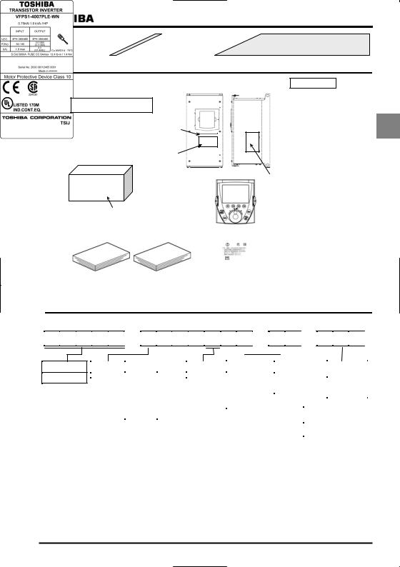
1.1Check the product
Type indication |
|
Inverter main unit |
|
|
|
VF-PS1 3PH-200/240V 0.75kW/1HP
Series name
Power supply Type indication
Motor capacity
Carton box |
Warning label |
Name plate
|
|
|
Operation panel |
|
||||
|
|
|
|
|
*1) |
|
|
|
|
|
Type indication |
|
|
|
|
||
|
|
label |
|
|
|
|
||
|
|
|
|
|
|
|
||
Instruction manuals (2 volumes) |
|
|
|
|
||||
Warning label |
|
|||||||
This manual |
|
E6581386 |
|
|||||
|
|
|
|
|
||||
|
|
|
|
|
|
|
|
|
|
|
|
|
|
|
|
|
|
|
|
|
|
|
|
|
DANGER |
|
|
|
|
|
|
|
|
Risk of injury, electric shock or fire. |
|
|
|
|
|
|
|
|
Read the Instruction Manual. |
|
|
|
|
|
|
|
|
Do not open the cover while power is applied or |
|
|
|
|
|
|
|
|
for 15 minutes after power has been removed. |
|
|
|
|
|
|
|
|
Ensure proper earth connection. |
|
Name plate
1
Inverter Type
Applicable motor
Invert rated output capacity
Power supply
Related input current
Related output current
Serial No.
*1): Operation panel is not attached to the inverter main unit at the delivery. Refer to 1.3.1 and attach the panel to the unit before installing the inverter.
1.2 Contents of the product code
Explanation of the type and form written on the label.
Type Form Special specification code
 V F P S 1
  -
-  4
4  0 0 7
0 0 7  P
P  L
L  E
E  -
-  W
W  N
N  -
-  A
A  2
2  2
2 
Model name
TOSVERT VF-PS1 series
|
|
|
|
|
|
|
|
|
|
|
|
|
|
|
|
|
|
|
|
|
|
|
|
|
|
|
|
|
|
|
|
|
|
|
|
|
|
|
|
|
|
|
|
|
|
|
|
|
|
|
|
|
|
|
|
|
|
|
|
|
|
|
|
Voltage class |
|
Applicable motor capacity |
Operation panel |
|
Additional functions I |
|
Additional functions II |
|
|
Special |
|||||||||||||||||||||
|
|
|
|
|
|
|
|
|
|
|
|
|
|
|
|
|
|
|
|
|
|
|
|
|
|
|
|
|
specification code |
||
4: 380V~480V |
|
004:0.4kW |
185:18.5kW |
P: Provided |
|
L: Built-in EMC filter |
|
E: Totally enclosed |
|
|
|||||||||||||||||||||
|
|
007:0.75kW |
220:22kW |
|
|
|
|
|
(class A) |
|
|
box type |
|
|
A : Special |
||||||||||||||||
|
|
015:1.5kW |
300:30kW |
|
|
|
|
+ |
|
|
|
|
Y: Others |
|
|
specification code |
|||||||||||||||
|
|
|
|
|
|
|
basic filter |
|
|
|
|||||||||||||||||||||
|
|
022:2.2kW |
370:37kW |
|
|
|
|
|
|
|
(non-standard) |
|
|
( is a number) |
|||||||||||||||||
|
|
|
|
|
|
D: Built-in EMC filter |
|
|
|
|
|||||||||||||||||||||
|
|
037:3.7kW |
450:45kW |
|
|
|
|
|
(class B) |
|
|
|
|
|
|
|
|
|
|
|
|
||||||||||
|
|
|
|
|
|
|
|
|
|
|
|
|
|
|
|
||||||||||||||||
|
|
055:5.5kW |
550:55kW |
|
|
|
|
+ |
|
|
|
|
|
|
|
|
|
|
|
|
|
|
|
||||||||
|
|
075:7.5kW |
750:75kW |
|
|
|
|
|
basic filter |
|
|
|
|
|
|
|
|
|
|
|
|
||||||||||
|
|
110:11kW |
900:90kW |
|
|
|
|
|
|
|
|
|
|
|
|
|
|
|
|
|
Default interface |
|
|
||||||||
|
|
150:15kW |
|
|
|
|
|
|
|
|
|
|
|
|
|
|
|
|
|
|
|
|
|
logic (*1) |
|
|
|
|
|||
|
|
|
|
|
|
|
|
|
|
|
|
|
|
|
|
|
|
|
|
|
|
|
|
|
|
|
|
|
|||
|
|
|
|
|
|
|
|
|
|
|
|
|
|
|
|
|
|
|
|
|
|
|
|
|
WN: Negative |
|
|
||||
|
|
|
|
|
|
|
|
|
|
|
|
|
|
|
|
|
|
|
|
|
|
|
|
|
WP: Positive |
|
|
||||
|
|
|
|
|
|
|
|
|
|
|
|
|
|
|
|
|
|
|
|
|
|
|
|
|
|
|
|
|
|
|
|
*1): This code represents the factory default logic setting. You can switch from one input/output logic to the other using slide switch SW1. For more details, refer to the manual E6581386 Section 2.3.2.
A-1
E6581429
1.3 Structure of the main body
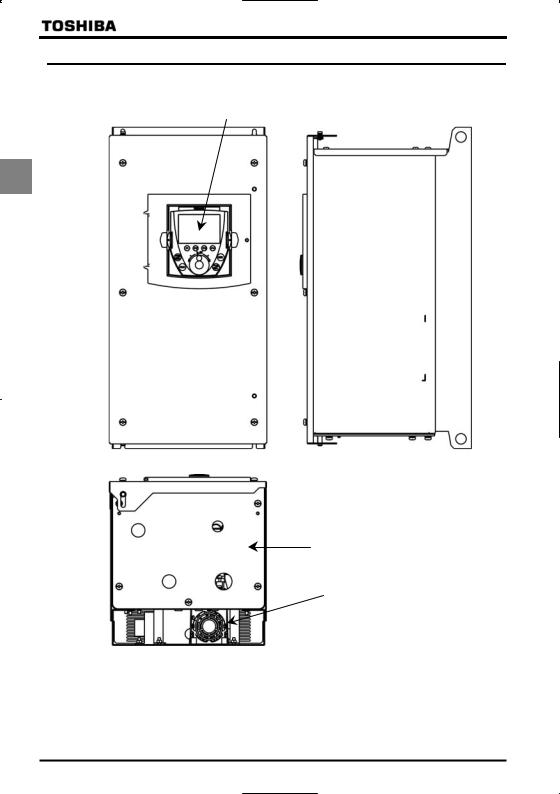
1.3.1 Names and functions
1) Outside view
Operation panel (Note)
1
[ Front view ] |
[ Side view ] |
Wiring port plate
Cooling fan
[ Bottom view ]
Note: Operation panel is not attached to the inverter main unit at the delivery. Attach the panel at the position of the upper figure before installing the inverter.
A-2
E6581429
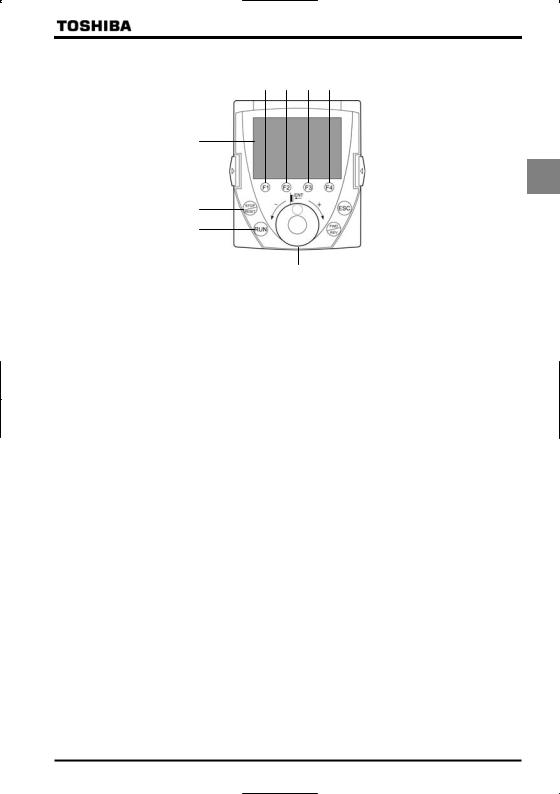
QOperation panel
Totally enclosed box type VF-PS1 series have a special operation panel.
(2)(3) (4) (5)
(1)
1
(9) |
|
|
(6) |
|
|||
(8) |
|
|
(7) |
|
|
(10)
(1): LCD panel
For explanation of windows displayed, see the next page.
(2) to (5): [F1] to [F4] function keys
The function of each function key varies depending on the window currently displayed.
Refer to the next page and “6. List of function key functions”
(6): [ESC] key
Each time this key is pressed, modes change from one to another. Also, pressing this key brings you back to the window one level higher in the window hierarchy.
(7): [FWD/REV] key
Each time this key is pressed, the direction of operation changes between forward run and reverse run. (To use this key, parameter settings need to be changed. Refer to the next page.)
(8): [RUN] key
The drive starts operation.
(To use this key, parameter settings need to be changed. Refer to the nest page.)
(9): [STOP/RESET] key
The drive stops operation.
(To use this key, parameter settings need to be changed. Refer to the next page.) In case the inverter has tripped, pressing this key twice in a row resets the inverter.
* If multiple commands are entered by pressing the three keys [F2], [F3] and [F4] or [ESC], [FWD] and [RUN] in rapid succession, a stop command will be issued instead to stop operation.
(10): Control dial
In a menu window, turn the dial clockwise or counterclockwise to select a menu item (the item selected is highlighted) and press the dial to confirm the menu item selected.
Turn the dial clockwise (+) to select an item that follows the item currently selected.
Turn the dial counterclockwise (-) to select an item that precedes the item currently selected.
Selecting a menu item by turning the dial clockwise or counterclockwise and confirm the item selected by pressing the dial are referred to as “select/confirm an item.”
In a value setting window, turn the dial clockwise or counterclockwise to increment or decrement the value displayed, and press the dial to confirm the value specified.*1
Turn the dial clockwise (+) to increment the value.
Turn the dial counterclockwise (-) to decrement the value.
Turning the dial clockwise or counterclockwise to increment or decrement the value displayed and pressing the dial to confirm the value specified are referred to as “specify/confirm a value.”
*1: Some settings are executed only by tuning the control dial.
A-3

E6581429
QLCD panel
This section explains the features of windows available, using the top window of Status Monitor Mode as an example.
|
|
|
|
|
(1) |
|
|
|
|
|
|
|
|
|
|
|
(2) |
||||||
|
|
|
|
|
|
|
|
|
|
|
|
|
|
|
|
|
|
|
|
|
|
|
|
|
|
|
|
|
|
|
|
|
|
|
|
|
|
|
|
|
|
|
|
|
|
|
|
|
|
|
|
|
|
|
|
|
|
|
|
|
|
|
|
|
|
|
|
|
|
|
|
|
|
|
|
|
|
Status Monitor Mode |
|
|
|
|
|
|
|
(3) |
|||||||||
|
|
|
|
|
|
|
|
|
|
|
|
|
|||||||||||
|
|
|
|
|
|
Real-time information |
|
|
|
|
|
|
|||||||||||
|
|
|
|
|
|
Rotative direction |
FWD |
|
|
|
|
|
|
|
|||||||||
|
|
|
|
|
|
Frequency reference |
60.0Hz |
|
|
|
|
|
|
||||||||||
1 |
|
|
|
|
|
|
|
|
|
||||||||||||||
|
|
|
|
|
Output current |
90% |
|
|
|
|
|
|
|
||||||||||
|
|
|
|
|
(4) |
||||||||||||||||||
|
|
|
|
|
Input voltage |
99% |
|
|
|
||||||||||||||
|
|
|
|
|
|
Output voltage |
99% |
|
|
|
|
|
(5) |
||||||||||
|
|
|
|
|
|
|
|
|
|
|
|
|
|
|
|
|
|
|
|
|
|||
|
|
|
|
|
|
Top |
|
|
|
|
Prm |
|
|
|
|
|
|||||||
|
|
|
|
|
|
|
|
|
|
|
|
|
|
|
|||||||||
|
|
|
|
|
|
|
|||||||||||||||||
|
|
|
|
|
|
|
|
|
|
|
|
|
|
|
|
||||||||
|
|
|
|
|
|
|
|
|
|
|
|
|
|
|
|
|
|
|
|
|
|
|
|
|
|
|
|
|
|
|
|
|
|
|
|
|
|
|
|
|
|
|
|
|
|
|
|
|
|
|
|
|
|
|
|
|
|
|
|
|
|
|
|
|
|
|
|
|
|
|
|
|
(1): Displays the mode currently selected. |
(6) |
|
|
|
|
|
|
|||||||||||||||
|
|
|
|
|
|
|
|
|
|
||||||||||||||
|
(2): Displays the operating status of the inverter with a graphical symbol. |
|
|
|
|
|
|||||||||||||||||
|
|
|
|
(Rotating) |
: In operation |
|
|
|
|
|
|
|
|
|
|||||||||
|
|
|
|
|
|
|
|
|
|
|
|
|
|||||||||||
|
|
|
|
|
: Operation impossible (While the frequency is set at 0Hz, the [RUN] key is pressed.) |
||||||||||||||||||
|
|
|
|
|
|||||||||||||||||||
|
EOFF (blinking) |
: Waiting for emergency stop operation |
|
|
|
|
|
|
|
|
|
||||||||||||
(3): Displays the title or status of the window.
(4): Displays settings both in a menu form and numerically, or a list of various kinds of information.
(5): Displays the function assigned to each function key in an abbreviation or graphical symbol. The abbreviations and graphical symbols in the window correspond to the [F1] to [F4] keys, respectively starting from the left.
Top |
: In this example, pressing the [F1] key displays the Top View Mode window. |
|
|
|
: In this example, pressing the [F2] key displays the previous window. |
|
|
|
|
|
: In this example, pressing the [F3] key displays the next window. |
|
|
|
Prm |
: In this example, pressing the [F4] key displays the Parameter Setting Mode window. |
|
For details, refer to “5. List of function key functions”.
(6)Graphical symbols displayed vary depending on whether there are windows that precede or follow the current window.
: There are windows that precede and/or follow the current window. : There is no window that precedes or follows the current window.
QAbout changing parameter settings
By default, the inverter is set with parameters to the mode in which it controls the operation of the machine via a terminal board. Moreover, the inverter is set so that the switching between forward run and reverse run cannot be performed using its operation panel.
To operate the inverter using this unit, parameter settings need to be changed, as described below.
Parameter CMOd (Command input mode) |
= 1 |
(Pane/LCD-option) |
Parameter FMOd (Frequency input mode 1) |
= 4 |
(Pane/LCD-option) |
Parameter Fr (Panel FWD/REV selection) |
= 2 |
(Forward (switchable)), |
|
3 (Reverse (switchable)) |
|
This change of parameter settings makes it possible to start operation using the [RUN] key, to stop operation using the [STOP/RESET] key, and to switch between forward run and reverse run using the [FWD/REV] key. Furthermore, it allows you to set an operation frequency using the control dial.
Refer to “3.3.1 Setting a panel operation frequency.”
A-4
E6581429
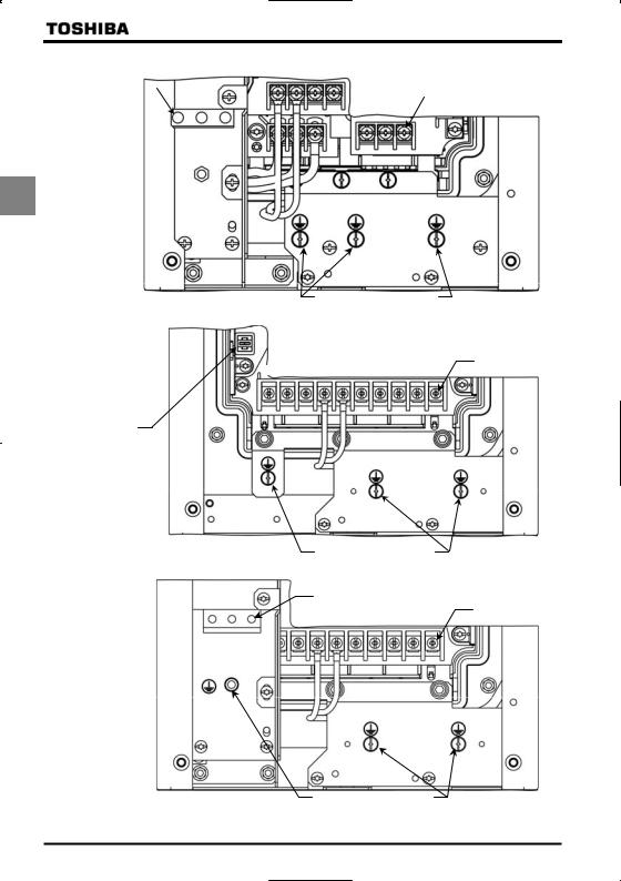
2) Main circuit terminal
VFPS1-4007PLE~4022PLE
PO PA/+ PB PC/-
M4 screw
U/T1 V/T2 W/T3
R/L1 S/L2 T/L3
1
Grounding capacitor switching switch
|
|
|
|
|
Grounding terminal |
||||
VFPS1-4007PDE~4022PDE |
|
|
(M5 screw) |
|
|
|
|
||
|
|
|
|||||||
|
|
|
|
|
|
|
|||
|
|
|
PO PA/+ PB PC/- |
||||||
M4 slotted head screw |
|
|
|
|
|
|
|
|
M4 screw |
|
|
|
|
|
|
|
|
||
|
|
R/L1 S/L2 T/L3 |
|||||||
|
|
|
|||||||
|
|
|
|
|
U/T1 V/T2 W/T3 |
||||
Grounding terminal (M5 screw)
VFPS1-4037PLE, 4055PLE
PO PA/+ PB PC/-
M4 screw
|
|
|
T/L3 |
U/T1 V/T2 W/T3 |
R/L1 |
|
S/L2 |
||
|
|
Grounding capacitor switching switch
Grounding terminal(M5screw)
A-5
E6581429
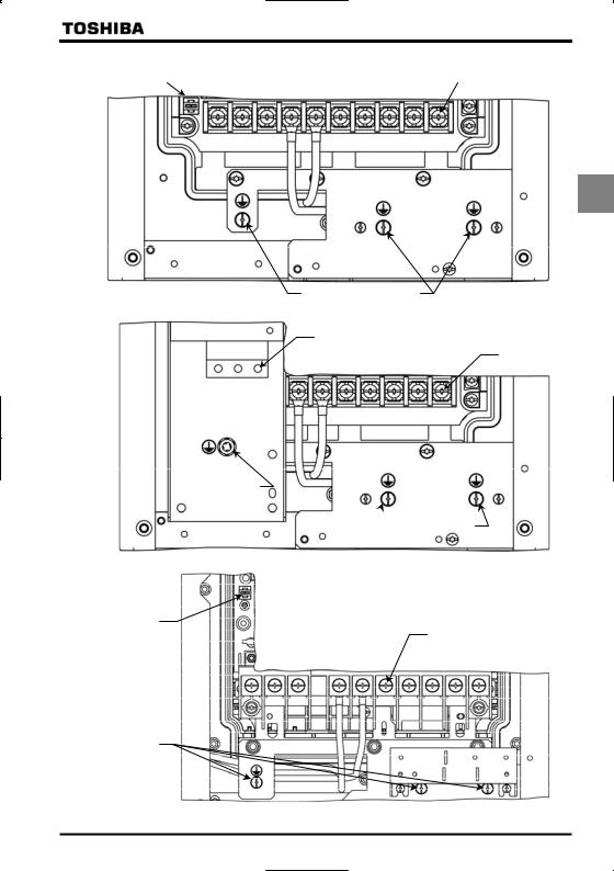
VFPS1-4037PDE, 4055PDE
|
|
|
PO PA/+ PB PC/- |
||
M4 slotted head |
|
|
|
|
|
screw |
|
|
M4 screw |
||
|
|
||||
|
|
R/L1 S/L2 |
T/L3 |
||
|
|
|
U/T1 V/T2 W/T3 |
||
1
Grounding terminal (M5 screw)
VFPS1-4075PLE, 4110PLE
M5 screw
R/L1 S/L2 T/L3 PO PA/+ PB PC/- U/T1 V/T2 W/T3
Grounding capacitor switching switch
Grounding terminal(M5 screw)
VFPS1-4075PDE, 4110PDE
M4 slotted head screw
M5 screw
PO PA/+ PB PC/- U/T1 V/T2 W/T3
R/L1 S/L2 T/L3
Grounding terminal(M5 screw)
A-6
E6581429
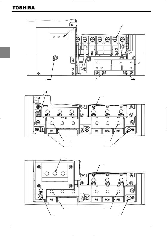
VFPS1-4150PLE
Grounding capacitor |
|
|
|
M5 screw |
switching switch |
|
|
|
|
|
R/L1 S/L2 T/L3 PO PA/+ PB PC/- U/T1V/T2 W/T3 |
|||
1
Grounding terminal(M5 screw)
VFPS1-4150PDE
M4 slotted head screw
M5 screw
PO PA/+ PB PC/- U/T1V/T2 W/T3
R/L1 T/L3
S/L2
Grounding terminal (M6 screw)
 Grounding terminal (M5 screw)
VFPS1-4185PLE, 4220PLE
Grounding capacitor
switching switch
M6 screw
R/L1 |
S/L2 T/L3 |
PO PA/+ PB PC/- U/T1V/T2 W/T3 |
grounding terminal (M5 screw)
A-7
E6581429
VFPS1-4185PDE, 4220PDE
|
|
M5 slotted head screw |
|
|
M6 screw |
|
|
|
|||
PO PA/+ PB PC/- U/T1 V/T2 |
W/T3 |
||||
R/L1 T/L3
S/L2
1
Grounding terminal(M6 screw) |
|
Grounding terminal(M5 screw) |
|
VFPS1-4300PLE
Grounding capacitor switching switch
M10 hexagon socket set screw
PO PA/+
Grounding terminal
(M10 hexagon socket set screw)
Grounding terminal(M5 screw)
VFPS1-4300PDE
M5 slotted head screw
M10 hexagon socket set screw
R/L1 S/L2 T/L3
PO PA/+
Grounding terminal
(M10 hexagon socket set screw)
Grounding terminal |
Grounding terminal(M5 screw) |
|
(M6 screw) |
||
|
A-8

E6581429
VFPS1-4370PLE, 4450PLE
Grounding capacitor switching switch
M10 hexagon socket set screw
1
PO PA/+
Grounding terminal
(M10 hexagon socket set screw) Grounding terminal(M5 screw)
VFPS1-4370PDE, 4450PDE
M6 slotted head screw
M10 hexagon socket set screw
R/L1 S/L2 T/L3
PO PA/+
Grounding terminal (M10 hexagon socket set screw)
Grounding terminal(M6 screw) |
Grounding terminal(M5 screw) |
|
|
||||||
|
|||||||||
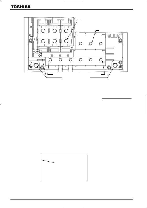
VFPS1-4550PLE~4900PLE |
|
|
|
|
|
|
|
|
|
|
|
Grounding capacitor |
|
|
|
|
|
|
|
|
|
switching switch |
|
|
|
M16 hexagon socket set screw |
|||
|
|
|
|
|
|
|
|||
R/L1 |
S/L2 |
T/L3 |
U/T1 |
V/T2 |
W/T3 |
||||
PE |
PO |
PA/+ |
PB |
PC/- |
|
PE |
|||
Grounding terminal (M16 hexagon socket set screw)
Grounding terminal(M8 screw)
A-9
E6581429
VFPS1-4550PDE~4900PDE
M20 hexagon socket head cap screw
M16 hexagon socket set screw
1 |
|
|
|
|
U/T1 |
V/T2 |
W/T3 |
|
R/L1 |
S/L2 |
|
T/L3 |
|
|
|
|
|
PE |
PO |
PA/+ |
PB |
PC/- |
PE |
grounding terminal(M16 hexagon socket set screw) grounding terminal(M8 screw)
Following power terminals are cage type ones.
-Input terminals of VFPS1-4007PDE to 4220PDE
-All power terminals of VFPS1-4300PLE to 4900PLE, VFPS1-4300PDE to 4900PDE For tightening torque and cable stripping length, refer to the table below.
|
|
|
|
DC terminals and |
|
|
|
|
||
|
Input terminals |
|
Output terminals |
|
Grounding terminals |
|||||
Type |
R/L1, S/L2, T/L3 |
|
P0, PA/+, PB, PC/-, |
|
*1) |
|
|
|||
|
|
|
U/T1, V/T2, W/T3 |
|
|
|
|
|||
VFPS1- |
|
|
|
|
|
|
|
|||
Tightening torque |
Stripping |
Tightening torque |
|
Stripping |
Tightening torque |
Stripping |
||||
|
|
|||||||||
|
length |
|
length |
length |
||||||
|
|
|
|
|
|
|
|
|||
|
N·m |
lb·ins |
mm |
N·m |
lb·ins |
|
mm |
|
|
mm |
4300PLE |
24 |
212 |
22 |
24 |
212 |
|
22 |
24 |
212 |
22 |
4370PLE, 4450PLE |
24 |
212 |
22 |
24 |
212 |
|
22 |
24 |
212 |
22 |
4550PLE~4900PLE |
41 |
360 |
34 |
41 |
360 |
|
34 |
41 |
360 |
34 |
4007PDE~4022PDE |
0.7 |
6.3 |
8 |
- |
- |
|
- |
- |
- |
- |
4037PDE, 4055PDE |
0.7 |
6.3 |
8 |
- |
- |
|
- |
- |
- |
- |
4075PDE, 4110PDE |
1.7 |
15.2 |
9 |
- |
- |
|
- |
- |
- |
- |
4150PDE |
1.7 |
15.2 |
11 |
- |
- |
|
- |
- |
- |
- |
4185PDE, 4220PDE |
2.2 |
19.6 |
16 |
- |
- |
|
- |
- |
- |
- |
4300PDE |
4.3 |
38.4 |
19 |
24 |
212 |
|
22 |
24 |
212 |
22 |
4370PDE, 4450PDE |
7 |
62.6 |
24 |
24 |
212 |
|
22 |
24 |
212 |
22 |
4550PDE~4900PDE |
25 |
221 |
27 |
41 |
360 |
|
34 |
41 |
360 |
34 |
*1) For 4300PLE to 4900PLE and 4300PDE to 4900PDE, these values are for PE terminals (cage type ones). Refer to following table for tightening torque for other grounding terminals.
Recommended tightening torque for power terminal screws
|
N·m |
lb·ins |
M 3 |
0.6 |
5.3 |
M 4 |
1.4 |
12.4 |
M 5 |
3.0 |
26.6 |
M 6 |
5.4 |
47.8 |
M 8 |
12.0 |
106 |
M10 |
24.0 |
212 |
M12 |
41.0 |
360 |
A-10
 Loading...