

Page 1

Model E112 / F112
SERVICE MANUAL
Manual No. 513632 Rev.3
Page 2

Page 3

This manual provides basic information about the machine. Instructions and suggestions are
given covering its operation and care.
The illustrations and specifi cations are not binding in detail. We reserve the right to make
changes to the machine without notice, and without incurring any obligation to modify or provide new parts for machines built prior to date of change.
DO NOT ATTEMPT to operate the machine until instructions and safety precautions in this
manual are read completely and are thoroughly understood. If problems develop or questions
arise in connection with installation, operation, or servicing of the machine, contact Stoelting.
stoeltingfoodservice.com
Stoelting Foodservice Equipment
502 Highway 67
Kiel, WI 53042-1600
U.S.A.
Main Tel: 800.558.5807
Fax: 920.894.7029
Customer Service: 888.429.5920
Fax: 800.545.0662
Email: foodservice@stoelting.com
© 2014 PW Stoelting, LLC
Page 4

A Few Words About Safety
Safety Information
Read and understand the entire manual before
operating or maintaining Stoelting equipment.
This manual provides the operator with information
for the safe operation and maintenance of Stoelting
equipment. As with any machine, there are hazards
associated with their operation. For this reason safety
is emphasized throughout the manual. To highlight
specifi c safety information, the following safety defi ni-
tions are provided to assist the reader.
The purpose of safety symbols is to attract your attention to possible dangers. The safety symbols, and
their explanations, deserve your careful attention
and understanding. The safety warnings do not by
themselves eliminate any danger. The instructions
or warnings they give are not substitutes for proper
accident prevention measures.
If you need to replace a part, use genuine Stoelting
parts with the correct part number or an equivalent
part. We strongly recommend that you do not use
replacement parts of inferior quality.
Safety Alert Symbol:
This symbol Indicates danger, warning or caution.
Attention is required in order to avoid serious personal injury. The message that follows the symbol
contains important information about safety.
Signal Word:
Signal words are distinctive words used throughout
this manual that alert the reader to the existence and
relative degree of a hazard.
WARNING
The signal word “WARNING” indicates a potentially
hazardous situation, which, if not avoided, may result
in death or serious injury and equipment/property
damage.
CAUTION
The signal word “CAUTION” indicates a potentially
hazardous situation, which, if not avoided, may result
in minor or moderate injury and equipment/property
damage.
CAUTION
The signal word “CAUTION” not preceded by the
safety alert symbol indicates a potentially hazardous
situation, which, if not avoided, may result in equipment/property damage.
NOTE (or NOTICE)
The signal word “NOTICE” indicates information or
procedures that relate directly or indirectly to the
safety of personnel or equipment/property.
Page 5

TABLE OF
CONTENTS
Section Description Page
1 Description and Specifi cations
1.1 Description .................................................................................................. 1
1.2 Specifi cations ............................................................................................. 2
1.3 Modes of Normal Operation .......................................................................4
1.4 Operation During an Error Mode ................................................................ 5
2 Installation Instructions
2.1 Safety Precautions ..................................................................................... 7
2.2 Shipment and Transit .................................................................................. 7
2.3 Machine Installation .................................................................................... 7
3 Initial Set-Up and Operation
3.1 Operator’s Safety Precautions ................................................................... 9
3.2 Operating Controls and Indicators ............................................................. 9
3.3 Sanitizing ....................................................................................................10
3.4 Freeze Down and Operation ......................................................................11
3.5 Mix Information ........................................................................................... 11
3.6 Removing Mix From Machine ..................................................................... 12
3.7 Cleaning the Machine ................................................................................. 12
3.8 Disassembly of Machine Parts ................................................................... 12
3.9 Cleaning and Sanitizing the Machine Parts ................................................ 13
3.10 Sanitize Machine ........................................................................................13
3.11 Assembly of Machine .................................................................................14
3.12 Routine Cleaning ........................................................................................ 15
3.13 Preventive Maintenance ............................................................................. 15
3.14 Extended Storage ....................................................................................... 17
4 Maintenance and Adjustments
4.1 Machine Adjustment ................................................................................... 19
4.2 Product Consistency Adjustment ................................................................ 19
4.3 Convert Slush to Shake .............................................................................. 19
4.4 Drive Belt Tension Adjustment ....................................................................19
4.5 Condenser Cleaning ................................................................................... 19
4.6 Preventative Maintenance .......................................................................... 20
4.7 Extended Storage ....................................................................................... 20
Page 6

Section Description Page
5 Refrigeration System
5.1 Refrigeration System .................................................................................. 21
5.2 Refrigerant Recovery and Evacuation ........................................................ 21
5.3 Refrigerant Charging ..................................................................................22
5.4 Compressor ................................................................................................22
5.5 Condenser ..................................................................................................24
5.6 Valves ......................................................................................................... 24
5.7 Capillary Tube .............................................................................................27
5.8 Filter Drier ................................................................................................... 28
6 Electrical and Mechanical Control Systems
6.1 Control Board ............................................................................................. 29
6.2 Contactor .................................................................................................... 29
6.3 Drive Motor ................................................................................................. 30
6.4 Capacitors .................................................................................................. 31
6.5 Gearbox ...................................................................................................... 32
6.6 Condenser Fan Motor (Air-Cooled Only) .................................................... 32
6.7 Switches ..................................................................................................... 32
7 Troubleshooting
7.1 Light Indicators ........................................................................................... 35
7.2 Troubleshooting .......................................................................................... 35
8 Replacement Parts
8.1 Decals, Lubrication, Panels & Legs ............................................................ 37
8.2 Auger Shaft and Faceplate Parts ...............................................................38
8.3 Hopper Parts .............................................................................................. 40
8.4 Machine Front & Spigot Switch Assembly .................................................. 41
8.5 E112 Parts .................................................................................................. 42
8.6 F112 Parts .................................................................................................. 44
8.7 Retrofi t Kits ................................................................................................. 46
8.8 Refrigeration Diagram ................................................................................ 47
8.9 E112 Wiring Diagram .................................................................................. 48
8.10 F112 Wiring Diagram ..................................................................................50
8.11 Autofi ll Options ........................................................................................... 52
Page 7
SECTION 1
DESCRIPTION AND SPECIFICATIONS
1.1 DESCRIPTION
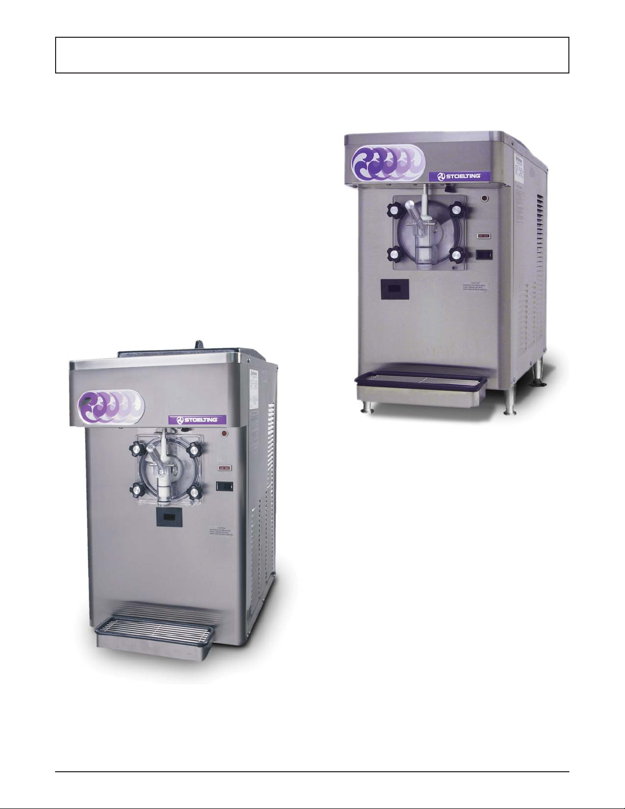
The Stoelting E112/F112 counter machines are gravity fed.
The machines are equipped with fully automatic controls
to provide a uniform product. They will operate with almost
any type of shake or frozen beverage mix. This manual is
designed to help qualifi ed service personnel and opera-
tors with the installation, operation and maintenance of
the Stoelting E112/F112 gravity machines.
Figure 1-1 Model F112
Figure 1-1 Model E112
Service Manual #513632 1 E112/F112 Model Machines
Page 8
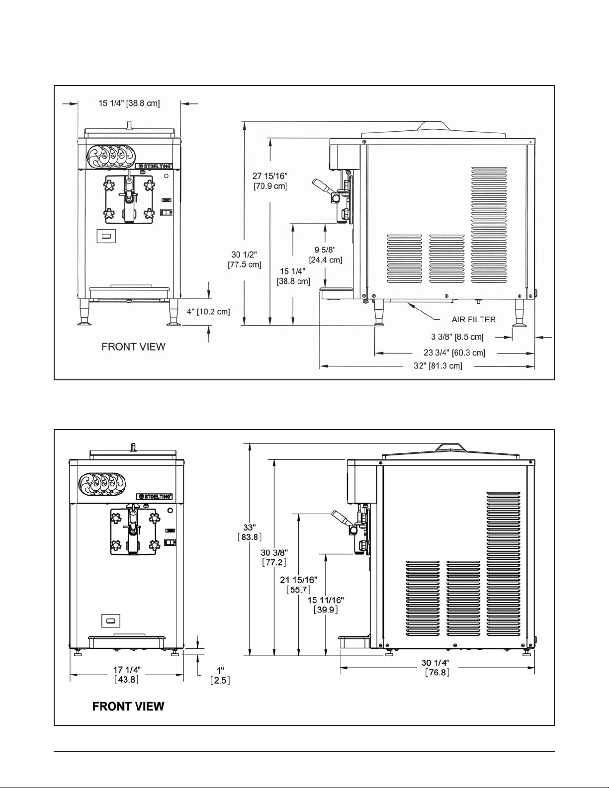
1.2 SPECIFICATIONS
E112
F112
Figure 1-2 Specifi cations
Service Manual #513632 2 E112/F112 Model Machines
Page 9

1.2 SPECIFICATIONS - CONTINUED
Model E112 Model F112
Dimensions Machine with crate Machine with crate
width 15-1/4’’ (38,7 cm) 17-1/2’’ (44,5 cm) 17-1/4’’ (43,8 cm) 29’’ (73,7 cm)
height 30-1/2’’ (77,5 cm) 35’’ (88,9 cm) 33’’ (83,8 cm) 44’’ (111,8 cm)
depth 32’’ (81,3 cm) 36-1/2’’ (92,7 cm) 30-1/4’’ (76,8 cm) 39’’ (99,1 cm)
Weight 205 lbs (92,9 kg) 215 lbs (97,5 kg) 288 lbs (130,6 kg) 315 lbs (142,8 kg)
Electrical 1 Phase, 115 VAC, 60Hz 1 Phase, 208-240 VAC, 60Hz
running amps 16A 10A
connection type NEMA5-20P power cord provided NEMA6-15P power cord provided
International Option 1 Phase, 220-240 VAC, 50Hz 1 Phase, 220-240 VAC, 50Hz
Compressor 6,000 Btu/hr 8,600 Btu/hr
Drive Motor 1/3 hp 3/4 hp
Air cooled units require 3” (7,6 cm) air
Air Flow
space on both sides or 4”
(10,2 cm) air space in back
for side-by-side installation
Air cooled units require 6” (15,24 cm)
air space on both sides
Plumbing Fittings N/A
Hopper Volume 3.625 gallon (13,73 liters) 5.375 gallon (20,35 liters)
Freezing Cylinder
Volume
Production Capacity 18 GPH (68,15 liters) 24 GPH (90,87 liters)
1.25 gallon (4,73 liters) 2.125 gallon (8,04 liters)
Water cooled units require 3/8” N.P.T.
water and drain fi ttings.
E112
Refrigerant R-404A
Charge 20 oz
Suction Pressure
(at 72°F)
Discharge Pressure
EPR Valve 59-61 psig
Shake 22-24 psig
Slush 30-32 psig
Shake 205-215 psig
Slush 200-205 psig
F112
Refrigerant R-404A
Charge
Suction Pressure
(at 72°F)
Discharge Pressure
EPR Valve 59-61 psig
(W/C) 20 oz
(A/C) 28 oz
Shake 30-32 psig
Slush 40 psig
Shake 245-250 psig
Slush 280 psig
Service Manual #513632 3 E112/F112 Model Machines
Page 10
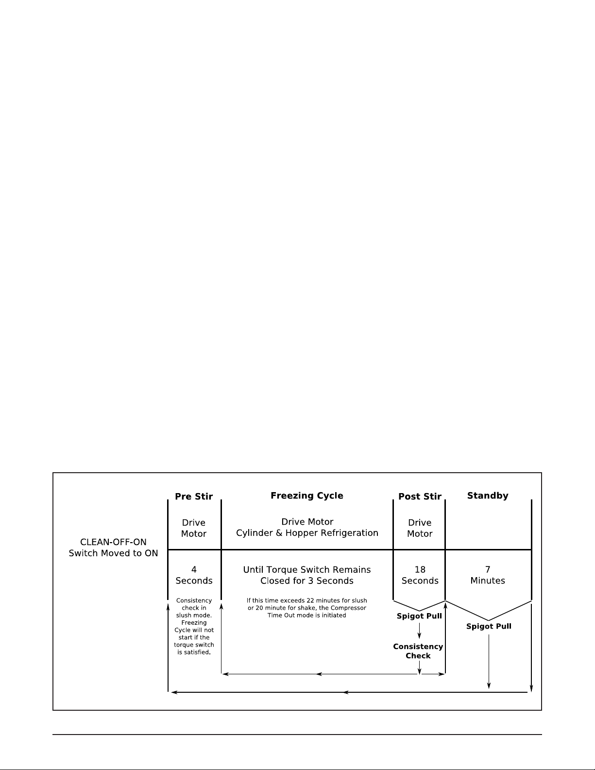
1.3 MODES OF NORMAL OPERATION
Following is an explanation of the normal operation modes
on the E112 and F112 (Refer to Figure 1-3).
NOTE
The following modes of operation are for the latest
versions of the control boards (521696.3, 521696.2
and 521696.1 Rev72). The older version of the
control has the following differences:
• The older control does not have slush mode with
a continuous drive
• The older control does not have a consistency
check during the pre stir in slush mode and the pre
stir is 3 seconds (instead of 4)
• The older control runs strictly on timers during an
error mode, and the cycle time during a drive motor
error is 7 minutes off/55 seconds on.
NOTE
Slush mode has two options: normal and continuous drive. With the continuous drive option selected,
the drive motor will run at all times, including
standby. To change the control between the two
options, refer to Section 4.3.
A. PRE STIR
When the CLEAN-OFF-ON is moved into the ON position
or when the spigot is opened, the drive motor will start
a 4-second pre stir. In slush mode, a consistency check
will determine if a freezing cycle will begin.
B. FREEZING CYCLE
After the pre stir, a freezing cycle begins. The freezing
cycle continues until the torque rod closes the torque
switch and keeps the switch closed for 3 seconds. If
product consistency is not met within 22 minutes for slush
or 20 minutes for shake, the machine will operate in the
compressor time out mode (See Section 1.4).
NOTE
If the spigot is pulled during a freezing cycle, the
20-minute or 22-minute timer will restart.
C. POST STIR
After the freezing cycle ends, the drive motor will continue
to run for an 18 second post stir. The post stir ensures
the product does not freeze to the cylinder. If the spigot
is opened during the post stir, the machine will check
consistency. If the product is at consistency, the machine
will move into standby. If the product is not at consistency,
the machine will start a freezing cycle.
D. STANDBY
After the post stir, the machine will be in standby. It will
remain in standby for 7 minutes or until the spigot is opened.
E. DEFROST MODE (SLUSH MODE ONLY)
If the spigot is not opened for 3 hours, defrost mode will
begin. The drive motor will run for 90 seconds every 7
minutes and the diagnostic light will remain lit.
After 5.5 hours or if the spigot is opened, normal operation mode will begin.
F. CLEAN MODE
When the CLEAN-OFF-ON switch is in the CLEAN position, the drive motor starts and will run for 20 minutes.
After the 20 minutes expire, the drive motor will stop and
the diagnostic light will fl ash three times every 4 seconds.
It will continue to fl ash until the CLEAN-OFF-ON switch
is moved out of the CLEAN position.
Figure 1-3 Modes of Normal Operation
Service Manual #513632 4 E112/F112 Model Machines
Page 11
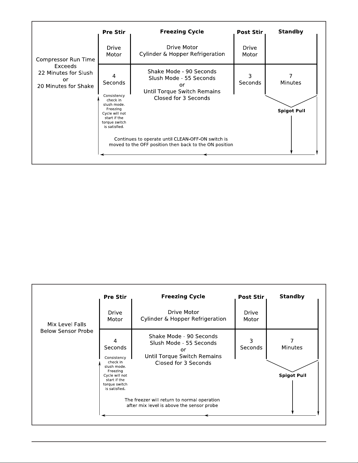
Figure 1-4 Compressor Time Out Mode
1.4 OPERATION DURING AN ERROR MODE
A. COMPRESSOR TIME OUT MODE
If the freezing cycle exceeds 20 minutes for shake or 22
minutes for slush, the machine will operate on timers. The
diagnostic light will fl ash once every 4 seconds (Refer to
Figure 1-4).
B. LOW MIX MODE
If the mix level falls below the sensor probe, the machine
will operate on timers. The ADD MIX light will fl ash. The
machine will continue to operate on timers until the mix
level in the hopper is above the sensor probe (Refer to
Figure 1-5).
Figure 1-5 Low Mix Mode
Service Manual #513632 5 E112/F112 Model Machines
Page 12
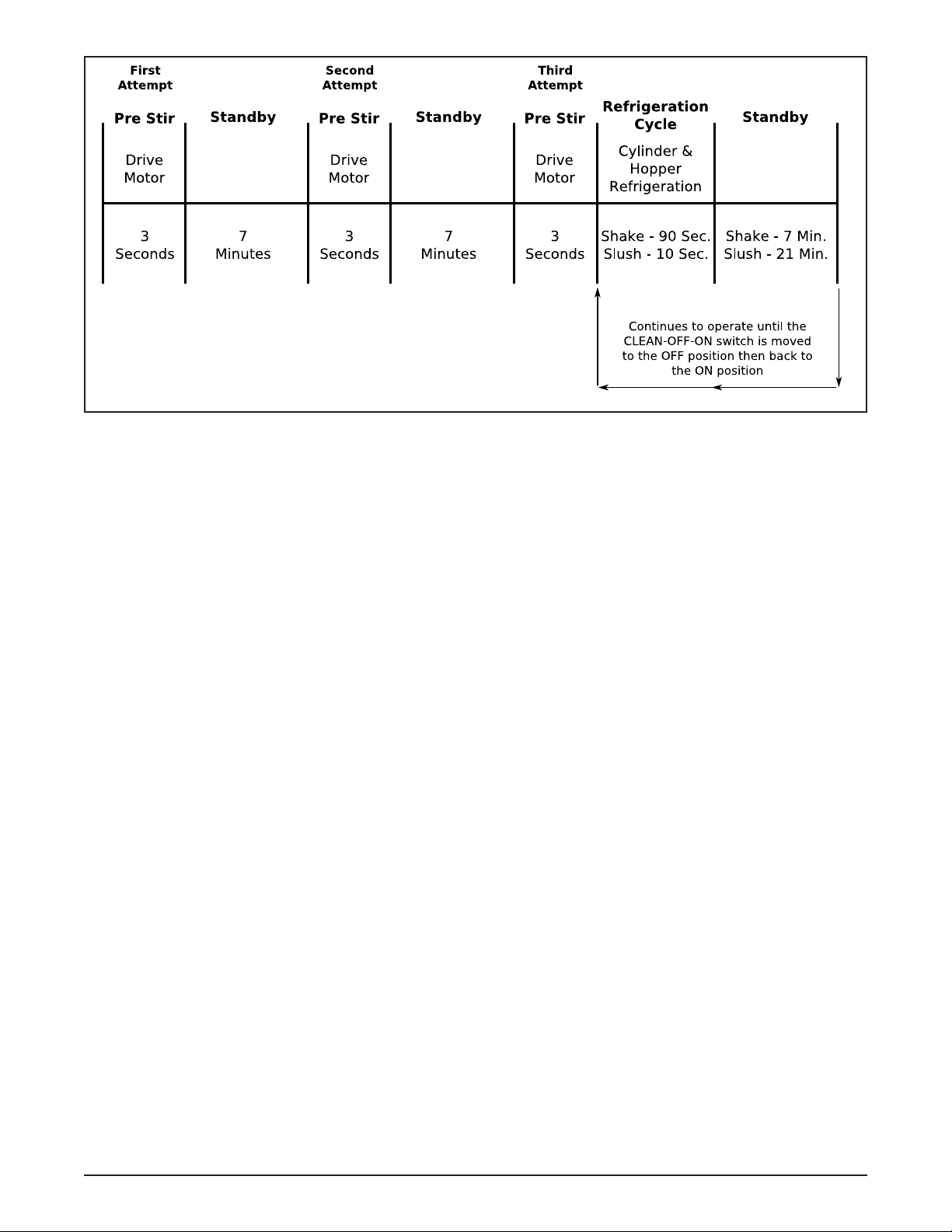
Figure 1-6 Drive Motor Error Mode
C. DRIVE MOTOR ERROR MODE
If the control does not sense current from the drive motor
during a pre stir, the machine will go into standby mode
for 7 minutes. After standby, the control will repeat the
pre stir and attempt to sense drive motor current. After
the third pre stir without sensing drive motor current, the
machine will operate on timers and the diagnostic light
will fl ash twice every four seconds (Refer to Figure 1-6).
The attempts to sense the drive motor current can be
substituted by pulling the spigot.
Service Manual #513632 6 E112/F112 Model Machines
Page 13
SECTION 2
INSTALLATION INSTRUCTIONS
2.1 SAFETY PRECAUTIONS
Do not attempt to operate the machine until the safety
precautions and operating instructions in this manual are
read completely and are thoroughly understood.
Take notice of all warning labels on the machine. The labels have been put there to help maintain a safe working
environment. The labels have been designed to withstand
washing and cleaning. All labels must remain legible for
the life of the machine. Labels should be checked periodically to be sure they can be recognized as warning labels.
If danger, warning or caution labels are needed, indicate
the part number, type of label, location of label, and quantity
required along with your address and mail to:
STOELTING, INC.
ATTENTION: Customer Service
502 Hwy. 67
Kiel, Wisconsin 53042
2.2 SHIPMENT AND TRANSIT
The machine has been assembled, operated and inspected
at the factory. Upon arrival at the fi nal destination, the
entire machine must be checked for any damage which
may have occurred during transit.
With the method of packaging used, the machine should
arrive in excellent condition. THE CARRIER IS RESPONSIBLE FOR ALL DAMAGE IN TRANSIT, WHETHER
VISIBLE OR CONCEALED. Do not pay the freight bill
until the machine has been checked for damage. Have
the carrier note any visible damage on the freight bill. If
concealed damage and/or shortage is found later, advise
the carrier within 10 days and request inspection. The
customer must place claim for damages and/or shortages
in shipment with the carrier. Stoelting, Inc. cannot make
any claims against the carrier.
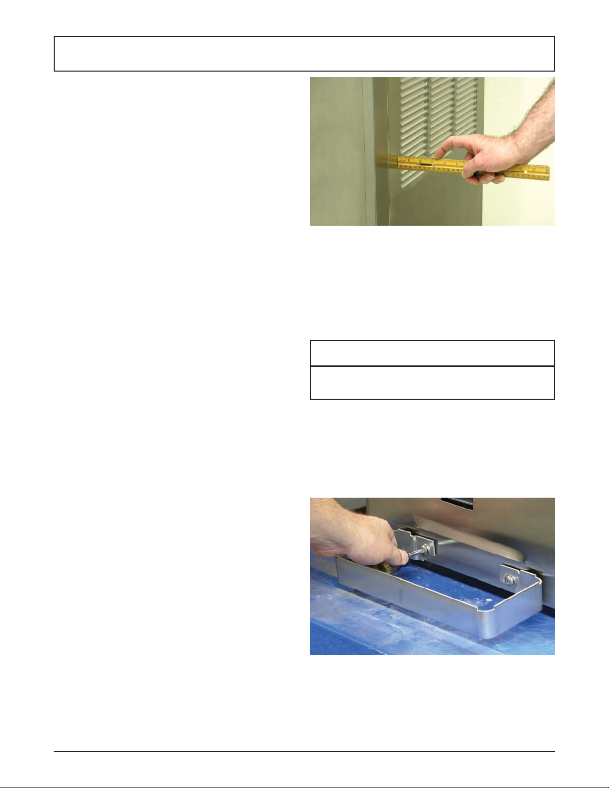
Figure 2-2 Space and Ventilation Requirements
D. Correct ventilation is required. The E112 requires
3” clearance on both sides. If the machine is
placed side-by-side next to other equipment, there
needs to be at lease 4” clearance at the back of
the machine. The air-cooled F112 requires 6”
clearance on both sides for proper air fl ow.
CAUTION
Failure to provide adequate ventilation will void
warranty.
D. Connect the drip tray bracket by loosening the
two screws at the front of the machine. Install
the bracket so that it rests on the nylon washer
between the two metal washers. Tighten the
screws.
2.3 MACHINE INSTALLATION
Installation of the machine involves moving the machine
close to its permanent location, removing all crating, setting in place, assembling parts, and cleaning.
A. Uncrate the machine.
B. Accurate leveling is necessary for correct drainage
of machine barrel and to insure correct overrun.
Place a bubble level on top of the machine at each
corner to check for level condition. If adjustment
is necessary, level the machine by turning the
bottom part of each leg in or out.
C. The F112 has a base gasket that must be installed.
Separate the gasket and install it with the seam
to the back. Make sure the angled side of the
gasket is facing up.
Service Manual #513632 7 E112/F112 Model Machines
E. Place the CLEAN-ON-OFF switch in the OFF
Figure 2-3 Drip Tray Bracket
position.
Page 14

WARNING
Do not alter or deform electrical plug in any way.
Altering the plug to fi t into an outlet of different con-
fi guration may cause fi re, risk of electrical shock,
product damage and will void warranty.
E. Connect the power cord to the proper power
supply. The plug on the E112 is designed for
115VAC, 20 amp duty and the plug on the F112
is designed for 208-240VAC / 15 amp duty. Check
the nameplate on your machine for proper supply.
The unit must be connected to a properly grounded
receptacle. The electrical cord furnished as part
of the machine has a three prong grounding
type plug. The use of an extension cord is not
recommended, if necessary use one with a size
12 gauge or heavier with ground wire. Do not use
an adapter to get around grounding requirement.
Service Manual #513632 8 E112/F112 Model Machines
Page 15
SECTION 3
INITIAL SET-UP AND OPERATION
3.1 OPERATOR’S SAFETY PRECAUTIONS
SAFE OPERATION IS NO ACCIDENT; observe these
rules:
A. Know the machine. Read and understand the
Operating Instructions.
B. Notice all warning labels on the machine.
C. Wear proper clothing. Avoid loose fi tting garments,
and remove watches, rings or jewelry that could
cause a serious accident.
D. Maintain a clean work area. Avoid accidents by
cleaning up the area and keeping it clean.
E. Stay alert at all times. Know which switch, push
button or control you are about to use and what
effect it is going to have.
F. Disconnect electrical cord for maintenance. Never
attempt to repair or perform maintenance on the
machine until the main electrical power has been
disconnected.
G. Do not operate under unsafe operating conditions.
Never operate the machine if unusual or excessive
noise or vibration occurs.
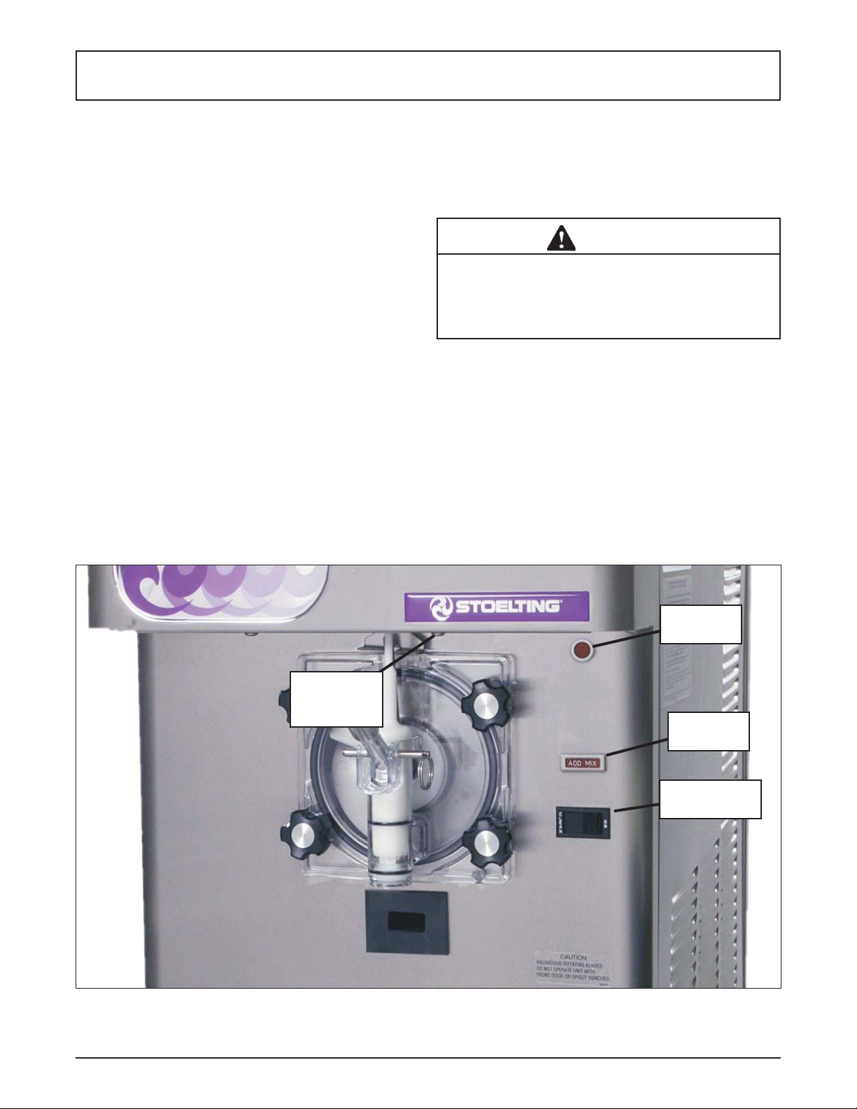
3.2 OPERATING CONTROLS AND INDICATORS
Before operating the machine, it is required that the operator know the function of each operating control. Refer
to Figure 3-1 for the location of the operating controls on
the machine.
WARNING
High voltage will shock, burn or cause death. The
OFF-ON switch must be placed in the OFF position
prior to disassembling for cleaning or servicing. Do
not operate machine with cabinet panels removed.
A. Spigot Switch
The spigot switch will automatically start the auger
drive and refrigeration systems when the spigot
is opened to dispense product. When the spigot
is closed, the drive motor and compressor will
remain on until the product in the freezing cylinder
reaches the proper consistency..
Consistency
Adjustment
Screw
Figure 3-1 Controls
Diagnostic
Light
Add Mix
Indicator
Clean/Off/On
Switch
Service Manual #513632 9 E112/F112 Model Machines
Page 16

B. CLEAN-OFF-ON Switch
The CLEAN-OFF-ON switch is used to supply
power to the control circuit. When the switch
is in the OFF (middle) position, power will not
be supplied to the control board or refrigeration
system. When the switch is in the ON position,
the machine will operate in the freezing mode.
When the switch is in the CLEAN position, all
refrigeration will stop and the auger will start
rotating.
C. ADD MIX Light
The ADD MIX light will fl ash to alert the operator
to a low mix condition. It does so by monitoring
the mix level in the hopper. When the ADD MIX
light is fl ashing, refi ll hopper immediately.
NOTE
Failure to refi ll hopper immediately may result in
operational problems.
D. Diagnostic Light
The Diagnostic Light will fl ash if an error occurs.
The light will fl ash once if there is a compressor
error. There will be two quick fl ashes if there is an
auger error. And there will be three quick fl ashes
if the machine is left in clean mode for more than
20 minutes. Refer to the troubleshooting section
for details.
E. Consistency Adjustment Screw
The Consistency Adjustment Screw increases or
decreases product consistency. A tension spring is
connected to the screw and changes the amount
of torque needed to complete a refrigeration cycle.
Turn the knob clockwise to increase consistency
or counterclockwise to decrease consistency.
NOTE
An additional spring is included with the machine
behind the header panel. The additional spring can
be installed for use with shake mixes when a higher
consistency is required. Do not use the optional
spring with slush mixes.
F. Front Door Safety Switch
The front door safety switch prevents the auger
from turning when the front door is removed. The
switch is open when the door is not in place and
closed when the door is properly installed.
G. Autofi ll Kit - Optional (E112 Part 2183807, F1 12
Part 2187101)
The autofi ll kit is used with a pump to keep the
hopper fi lled. The autofi ll kit is for use with non-
potentially hazardous food substances; non-dairy.
Refer to Section 5-4 for Autofi ll options.
H. Light Kit - Optional (E112 Part 2183800, F1 12
Part 2187102)
The light kit is installed behind the header panel
and illuminates a translucent header panel.
I. Bottle Rack Kit - Optional (E112 Part 2187100,
F112 Part 2187040 or 2187024)
The bottle rack kit is installed onto the header
panel and holds 7 fl avor bottles (13 bottles on
the 2187024).
J. Spinner Kit - Optional (E112 Part 2187103,
F112 Part 2187031)
The spinner kit is installed on the front of the
machine and offers blended frozen beverages.
3.3 SANITIZING
Sanitizing must be done after the machine is cleaned and
just before the hopper is fi lled with mix. Sanitizing the night
before is not effective. However, you should always clean
the machine and parts after each use.
The United States Department of Agriculture and
the Food and Drug Administration require that all
cleaning and sanitizing solutions used with food
processing equipment be certifi ed for this use.
When sanitizing the machine, refer to local sanitary regulations for applicable codes and recommended sanitizing
products and procedures. The frequency of sanitizing
must comply with local health regulations.
Mix sanitizer according to manufacturer’s instructions to
provide a 100 parts per million (ppm) strength solution and
check the solution with chlorine test strips. Mix sanitizer
in quantities of no less than 2 gallons (7.5 liters) of 90°
to 110°F (32° to 43°C) water. Allow sanitizer to contact
the surfaces to be sanitized for 5 minutes. Any sanitizer
must be used only in accordance with the manufacturer’s
instructions.
CAUTION
Do not allow sanitizer to remain in contact with
stainless steel parts for prolonged periods. Prolonged contact of sanitizer with machine may cause
corrosion of stainless steel parts.
In general, sanitizing may be conducted as follows:
A. Prepare Stera-Sheen Green Label Sanitizer
or equivalent according to manufacturer’s
instructions to provide a 100 ppm strength solution.
Mix the sanitizer in quantities of no less than
2 gallons of 90° to 110°F (32° to 43°C) water.
Check the strength of the sanitizing solution. Use
a chlorine test strip and color chart to make sure
the solution has 100 ppm. Any sanitizer must be
used only in accordance with the manufacturer’s
instructions.
Service Manual #513632 10 E112/F112 Model Machines
Page 17

Figure 3-2 Mix Inlet Regulator
B. If using a shake mix, place the mix inlet regulator
into hopper (Refer to Figure 3-2). If using a slush
mix, the mix inlet regulator is not required.
C. Pour the sanitizing solution into the hopper and
place the switch in the CLEAN position. Check
for leaks.
D. Clean sides of hopper, mix inlet regulator and
underside of hopper cover using a soft bristle
brush dipped in the sanitizing solution (Refer to
Figure 3-3).
3.4 FREEZE DOWN AND OPERATION
This section covers the recommended operating procedures for the safe operation of the machine.
A. Sanitize just prior to use.
B. Place the switch in the OFF (middle) position.
NOTE
Make sure the mix inlet regulator is in place before
adding shake mixes. This is not necessary for
slush mixes.
C. Pour approximately 1/2 gallon of fully thawed mix
into the hopper. Open spigot and drain a small
amount of mix to remove any remaining sanitizer.
D. Fill the hopper with pre-chilled (40°F or 4°C) mix.
NOTE
Do not overfi ll the hopper. Mix level must be below
the air inlet tube on the mix inlet regulator.
E. Place the switch in the ON position.
NOTE
After the drive motor starts, there is a 3 or 4 second
delay before the compressor starts.
F. After 8 to 12 minutes the product will be at
consistency and will be ready to serve. Freeze
down time may vary depending on mix type and
ambient temperatures.
G. To dispense, pull the spigot handle down to open
the spigot.
H. The machine is designed to dispense the product
at a reasonable draw rate. If the machine is
overdrawn, the result is a soft product or a product
that will not dispense at all. If this should occur,
allow the machine to run for approximately 30
seconds before dispensing additional product.
I. Do not operate the machine when the ADD MIX
light is on. Refi ll the hopper immediately.
Figure 3-3 Sanitizing hopper
E. After fi ve minutes, place a bucket under the spigot
and open spigot to drain most sanitizing solution.
Leave a small amount of the sanitizing solution
in the freezing cylinder. Place the switch in the
OFF (middle) position.
F. Collect the remaining sanitizing solution in a cup
and test the chlorine contents with a new test strip.
A reading of 100 ppm or more is acceptable.
If the reading is less than 100 ppm, sanitize the
machine again.
If the reading is less than 100 ppm after sanitizing
the second time, disassemble and wash the
machine again.
Service Manual #513632 11 E112/F112 Model Machines
3.5 MIX INFORMATION
Mix can vary considerably from one manufacturer to
another. Differences in the amount of butterfat content
and quantity and quality of other ingredients have a
direct bearing on the fi nished frozen product. A change
in machine performance that cannot be explained by a
technical problem may be related to the mix.
Proper product serving temperature varies from one
manufacturer’s mix to another. Shake and stackable slush
mixes provide satisfactory product from 24° to 28°F (-4°
to -2°C).
When checking the temperature, stir the thermometer in
the frozen product to obtain an accurate reading.
Page 18
Old mix or mix that has been stored at elevated temperatures will produce poor-quality product with a bad taste
and unacceptable appearance. To retard bacteria growth
in dairy based mixes, the best storage temperature range
is between 33° to 38°F (0.5° to 3.3°C).
Some shake mixes tend to foam more than others. If foam
appears in the hopper, skim off with a sanitized utensil
and discard. Periodically, stir the mix in the hopper with
a sanitized utensil to help prevent excess foam.
3.8 DISASSEMBLY OF MACHINE PARTS
Inspection for worn or broken parts should be made each
time the machine is disassembled. All worn or broken
parts should be replaced to ensure safety to both the
operator and the customer and to maintain good machine
performance and a quality product. Frequency of cleaning
must comply with the local health regulations.
To disassemble the machine, refer to the following steps:
3.6 REMOVING MIX FROM MACHINE
To remove the mix from the machine, refer to the following steps:
A. If removing shake mix, pull the mix inlet regulator
straight up and remove it from the hopper.
B. Place the switch in the CLEAN position to rotate
the auger. Allow the mix to agitate in freezing
cylinder until the mix has become liquid, about 5
minutes.
C. Drain the liquid mix by opening the spigot. A
container should be placed under the spigot to
collect the liquid mix.
D. Place the switch in the OFF (middle) position.
3.7 CLEANING THE MACHINE
NOTE
The frequency of cleaning the machine and machine parts must comply with local health regulations.
After the mix has been removed from the machine, the
machine must be cleaned. To clean the machine, refer
to the following steps:
A. Close the spigot and fi ll the hopper with 2 gallons
(8 liters) of tap water.
B. Place the switch in the CLEAN position. The auger
will start to rotate.
C. Allow the water to agitate for approximately 30
seconds.
D. Open the spigot to drain the water. Remember to
place a container under the spigot to catch the
water. When the water has drained, place the
switch in the OFF (middle) position. Allow the
freezing cylinder to drain completely.
E. Prepare sanitizing solution according to
manufacturer’s instructions to provide a 100 ppm
strength solution. Mix the sanitizer in quantities
of no less than 2 gallons of 90° to 110°F (32° to
43°C) water. Check the strength of the sanitizing
solution. Use a chlorine test strip and color chart
to make sure the solution has 100 ppm. Repeat
steps A through D using the sanitizing solution.
CAUTION
Hazardous Moving Parts.
Revolving auger shaft can grab and cause injury.
Place the switch in the OFF (middle) position before
disassembling for cleaning or servicing.
A. Remove hopper cover. Remove the mix inlet
regulator from the hopper (if installed).
B. Pull out the spigot pin by its ring (Refer to Figure
3-4).
Figure 3-4 Remove Spigot Pin
C. Remove the spigot handle.
D. Remove front door by turning the circular knobs
and then pulling door off the studs.
NOTE
When removing front door, entire door and stator
assembly will come out as well.
E. Remove torque rod from stator assembly.
F. Remove quad ring from groove in front door.
G. Remove stator bar. Remove o-ring and white
bushing from stator bar.
H. Remove auger support bushing.
I. Turn the spigot body until the ice breaker bar
can be removed. Remove breaker bar (Refer to
Figure 3-5).
Service Manual #513632 12 E112/F112 Model Machines
Page 19

Figure 3-5 Spigot and Ice Breaker Bar Removal
Figure 3-7 Cleaning Freezing Cylinder
J. Remove spigot body from the front door.
K. Remove o-rings (2) from the spigot by fi rst wiping
off the lubricant using a clean paper towel. Then
squeeze the o-ring upward with a dry cloth. When
a loop is formed, roll the o-ring out of the groove
(Refer to Figure 3-6).
L. Remove auger assembly from the freezing cylinder
and remove auger blades.
M. Remove rear seal and o-ring from auger.
N. Remove drain tray, drip tray and drip tray grid.
A. Prepare Stera-Sheen or equivalent cleaner in
2 gallons of 90° to 110°F (32° to 43°C) water
following manufacturers instructions.
B. Prepare sanitizing solution according to
manufacturer’s instructions to provide a 100 ppm
strength solution. Mix the sanitizer in quantities
of no less than 2 gallons of 90° to 110°F (32° to
43°C) water. Check the strength of the sanitizing
solution. Use a chlorine test strip and color chart
to make sure the solution has 100 ppm.
D. Place all parts in the cleaning solution and clean
the parts with the provided brushes. Rinse all
parts with clean 90° to 110°F (32° to 43°C) water.
Place the parts in the sanitizing solution.
E. Wash the hopper and freezing cylinder with the
90° to 110°F (32° to 43°C) cleaning solution and
brushes provided (Refer to Figure 3-7).
F. Clean the rear seal surfaces from the inside of
the freezing cylinder with the 90° to 110°F (32°
to 43°C) cleaning solution.
3.10 SANITIZE MACHINE
CAUTION
Figure 3-6 Removing O-Ring
3.9 CLEANING AND SANITIZING THE
MACHINE PARTS
Place all loose parts in a pan or container and take to
the wash sink for cleaning. Local and state health codes
dictate the procedure required. Some health codes require
a four-sink process (pre-wash, wash, rinse, sanitize, and
air-dry), while other codes require a three-sink process
(without the pre-wash step). The following procedures
are a general guideline only. Consult your local and state
health codes for procedures required in your location.
Service Manual #513632 13 E112/F112 Model Machines
Do not allow sanitizer to remain in contact with
stainless steel parts for prolonged periods. Prolonged contact of sanitizer with machine may cause
corrosion of stainless steel parts.
A. Use Stera-Sheen or equivalent sanitizing solution
mixed according to manufacturer’s instructions
to provide 100 parts per million strength solution.
Mix sanitizer in quantities of no less than 2 gallons
(7.5 liters) of 90° to 110°F (32° to 43°C) water.
Any sanitizer must be used only in accordance
with the manufacturer’s instructions.
Page 20

B. With the large brush provided, sanitize the rear
of the freezing cylinder by dipping the brush in
the sanitizing solution and brushing the rear of
the cylinder.
3.11 ASSEMBLY OF MACHINE
To assemble the machine parts, refer to the following steps:
NOTE
Petrol Gel sanitary lubricant or equivalent must be
used when lubrication of parts is specifi ed.
NOTE
The United States Department of Agriculture and
the Food and Drug Administration require that lubricants used on food processing equipment be certifi ed for this use. Use lubricants only in accordance
with the manufacturer’s instructions.
A. Assemble all o-rings onto the parts dry, without
lubrication. Then apply a thin fi lm of sanitary
lubrication to the exposed surfaces of the o-rings.
Also apply a thin fi lm of sanitary lubricant to the
inside and outside of the front auger support
bushing, and to the inside and outside of stator
support bushing.
B. Assemble the rear seal onto the auger with the
large end to the rear. Be sure the o-ring is in place
before installing the rear seal (Refer to Figure
3-8).
C. Put a small amount of spline lubricant on the hex
end of the auger shaft. A small container of spline
lubricant is shipped with the machine.
D. Install the plastic auger blade onto the auger.
E. Push the auger into the freezing cylinder and
rotate it slowly until the auger engages the drive
shaft.
F. Insert the spigot body into the front door.
NOTE
Press the o-rings against the spigot body when
inserting it into the front door to prevent damage.
G. Turn the spigot body until the ice breaker bar can
be inserted. Insert the breaker bar and rotate the
spigot body 90
H. Install the auger support bushing onto the front
door so the beveled edge of the bushing is against
the door.
I. Install the white stator support bushing onto the
rear of the stator bar and insert stator into spigot.
J. Insert the torque rod. The rod should be placed
through the hole in the stator bar.
K. Install the front door onto the machine.
NOTE
When installing the door onto the machine, the
torque rod must be placed in the center of the metal
torque actuator arm
L. Install the knobs on the machine studs.
M. Look for the proper seal between the freezing
cylinder, quad ring, and front door
Torque
Rod
Stator Bar
Bushing
Auger
Support
Bushing
Figure 3-9 Door and Stator Assembly
Stator Bar
Stator Bar
Front O-Ring
Stator Bar
Rear O-Ring
Quad
Ring
Service Manual #513632 14 E112/F112 Model Machines
Page 21

In addition to food safety, milkstone can cause premature
CAUTION
Do not place the mix inlet regulator into the hopper
before installing the auger. Attempting to install the
auger with the mix inlet regulator in place will damage the regulator.
N. Insert the spigot handle so the hole lines up and
insert the spigot pin.
O. Install the mix inlet regulator into the hopper if
using shake mix. If using slush mix, the mix inlet
regulator is not required.
P. Install the hopper cover, drain tray, drip tray, and
drip tray grid.
3.12 ROUTINE CLEANING
To remove spilled or dried mix from the machine exterior,
wash in the direction of the fi nish with warm soapy water
and wipe dry. Do not use highly abrasive materials as
they will mar the fi nish.
3.13 PREVENTIVE MAINTENANCE
Stoelting recommends that a maintenance schedule be
followed to keep the machine clean and operating properly.
CLEANING AND SANITIZING INFORMATION
Special consideration is required when it comes to food
safety and proper cleaning and sanitizing.
The following information has been compiled by Purdy
Products Company, makers of Stera-Sheen Green Label Cleaner/Sanitizer and specifi cally covers issues for
cleaning and sanitizing frozen dessert machines. This
information is meant to supplement a comprehensive
food safety program.
SOIL MATERIALS ASSOCIATED WITH FROZEN
DESSERT MACHINES
MILKFAT/BUTTERFAT – As components of ice-cream/
frozen custard mix, these soils will accumulate on the
interior surfaces of the machine and its parts. Fats are
diffi cult to remove and help attribute to milkstone build-up.
MILKSTONE – Is a white/gray fi lm that forms on equip-
ment and utensils that come in contact with dairy products.
These fi lms will accumulate slowly on surfaces because of
ineffective cleaning, use of hard water, or both. Milkstone
is usually a porous deposit, which will harbor microbial
contaminants and eventually defy sanitizing efforts.
Once milkstone has formed, it is very diffi cult to remove.
Without using the correct product and procedure, it is
nearly impossible to remove a thick layer of milkstone.
(NOTE: general-purpose cleaners DO NOT remove
milkstone.) This can lead to high bacteria counts and a
food safety dilemma.
IT IS BEST TO CONTROL MILKSTONE ON A DAILY BASIS BEFORE IT CAN BECOME A SIGNIFICANT FOOD
SAFETY PROBLEM.
Service Manual #513632 15 E112/F112 Model Machines
wear to machine parts which can add to costs for replacement parts or possibly more expensive repairs if worn
machine parts are not replaced once they have become
excessively worn.
IMPORTANT DIFFERENCES BETWEEN CLEANING
AND SANITIZING
CLEANING vs. SANITIZING
It is important to distinguish between cleaning and sanitizing. Although these terms may sound synonymous, they
are not. BOTH are required for adequate food safety and
proper machine maintenance.
CLEANING
• Is the removal of soil materials from a surface.
• Is a prerequisite for effective sanitizing.
NOTE
An UNCLEAN surface will harbor bacteria that can
defy sanitizing efforts.
Bacteria can develop and resist sanitizing efforts within
a layer of soil material (milkstone). Thorough cleaning
procedures that involve milkstone removal are critical for
operators of frozen dessert machines.
SANITIZING
• Kills bacteria.
• Can be effective on clean surfaces only.
NOTE
Using a SANITIZER on an unclean surface will not
guarantee a clean and safe frozen dessert machine.
PROPER DAILY MAINTENANCE: THE ONLY WAY T O
ASSURE FOOD SAFETY AND PRODUCT QUALITY
Proper daily maintenance can involve a wide variety
of products and procedures. Overall, the products and
procedures fall into three separate categories. (Please
note that this is a brief overview intended for informational
purposes only.)
1. CLEANING – This involves draining mix from
the freezing cylinder and rinsing the machine
with water. Next, a cleaner is run through the
machine. Then, the machine is disassembled
and removable parts are taken to the sink for
cleaning.
2. MILKSTONE REMOVAL – Since almost all
cleaners do not have the ability to remove
milkstone, the use of a delimer becomes
necessary. Although this procedure may not be
needed on a daily basis, it will usually follow the
cleaning procedure. It requires letting a delimer
solution soak in the machine for an extended
period of time. Individual parts are also soaked in
a deliming solution for an extended period of time
(more about delimers in Additional Information).
Page 22

3. SANITIZING – After the machine has been
cleaned and contains no milkstone, the machine
is reassembled. Then a FDA-approved sanitizing
solution is run through the machine to kill bacteria.
The machine is then ready for food preparation.
As a recommended cleaner and sanitizer for your frozen
dessert machine, STERA-SHEEN has proven to be one
of the best daily maintenance products for:
• CLEANING – Thorough removal of all solids
including butterfat and milk fat.
• MILKSTONE REMOVAL – Complete removal of
milkstone.
• SANITIZING – FDA-approved no rinse sanitizer
for food contact surfaces.
ADDITIONAL INFORMATION
THE USE OF DELIMERS
A delimer is a strong acid that has the ability to dissolve
milkstone. This type of chemical may become necessary
once high levels of milkstone have developed. While these
products are very effective for removing HIGH levels of
milkstone, they are not ideal for two reasons:
1. PRODUCT SAFETY – Strong acids are dangerous
chemicals and handling them requires safety
2. MACHINE DAMAGE – Strong acids will attack
metal and rubber causing premature wear of
parts. The use of a delimer needs to be closely
monitored to avoid damage to machine surfaces
and parts.
With proper daily use of STERA-SHEEN or its equivalent,
there is no need for the use of a DELIMER.
DO NOT USE BLEACH
• BLEACH HAS ABSOLUTELY NO CLEANING
PROPERTIES.
• BLEACH IS CORROSIVE. It can and will damage
components of the machine causing premature
wear and metal corrosion.
GENERAL PURPOSE CLEANERS
General purpose cleaners do not have the ability to remove milkstone. Milkstone will become a problem if not
remedied with additional products and procedures.
THE USE OF CHLORINE TEST STRIPS
“Test strips” are used to determine concentrations of
active chlorine in sanitizing solutions. To use the strips,
tear off a small portion and submerge it into the sanitizing
solution. Then, compare the color change to the color key
on the side of the test strip dispenser to determine the
approximate chlorine concentration.
The ideal concentration of chlorine needs to be 100 ppm
(as stated by the FDA).
NOTE
Follow the directions on the container for proper
concentration.
There are two main factors that contribute to falling chlorine
concentrations in a sanitizing solution.
1. PRODUCT USE – As the chlorine in the solution
is being used, chlorine concentrations fall.
2. TIME – As time passes, small amounts of chlorine
“evaporate” from the solution. (That is why you
can smell it.)
Sanitizing solutions should not be allowed to fall below
100 ppm chlorine. New solutions should be mixed once
old solutions become ineffective
B. DAILY
1. The exterior should be kept clean at all times to
preserve the luster of the stainless steel. A mild
alkaline cleaner is recommended. Use a soft cloth
or sponge to apply the cleaner.
C. WEEKLY
1. Check o-rings and rear seal for excessive wear
and replace if necessary.
2. Remove the drip tray by gently lifting up to
disengage from the support and pulling out. Clean
behind the drip tray and front of the machine with
a soap solution.
D. QUARTERLY
Air Cooled
The air-cooled condenser is a copper tube and aluminum
fi n type. Condensing is totally dependent upon airfl ow.
A plugged condenser fi lter, condenser, or restrictions in
the louvered panel will restrict airfl ow. This will lower the
capacity of the system and damage the compressor.
The condenser must be kept clean of dirt and grease. The
F112 must have a minimum of 6” (15.2 cm) ventilation on
the right and left sides of the unit for free fl ow of air. The
E112 must have 3” (7.6 cm) ventilation. Make sure the
machine is not pulling over 100° F (37° C) air from other
equipment in the area.
The condenser and condenser fi lter require periodic clean-
ing. To clean, refer to the following procedures.
E112 Air Cooled Condenser Cleaning
A. Unscrew the knob located on the underside of
the machine towards the front (Fig. 3-10).
B. Remove the fi lter bracket and remove the fi lter.
C. Visually inspect the condenser fi lter for dirt.
D. If the fi lter is dirty, vacuum or brush clean, rinse
with clean water and allow to dry before replacing
on the machine.
Service Manual #513632 16 E112/F112 Model Machines
Page 23

Figure 3-10 E112 Condenser Filter Removal
NOTE
If the condenser is not kept clean, refrigeration effi ciency will be lost.
F112 Air Cooled Condenser Cleaning
A. Remove the Phillips head screws from the bottom
of the right side panel, and then slide the panel
down and out.
B. To remove the condenser fi lter, grasp the top and
pull off. Visually inspect it for dirt. If the fi lter is
dirty, shake or brush excess dirt off the fi lter and
wash it in warm, soapy water. Once the fi lter is
clean rinse thoroughly in warm, clear water and
shake dry, taking care not to damage the fi lter in
any way (Fig. 3-11).
C. Visually inspect the condenser for dirt by shining
a light through the coil from the back (inside) of
the condenser.
D. If the condenser is dirty, place a wet towel over
the front (outside) of the condenser.
E. Using a vacuum, carefully clean the condenser
coil from the inside and outside of the machine.
A stiff bristled brush may help in releasing debris
from between the condenser coils.
Water Cooled (F112 only)
The water-cooled condenser is a tube and shell type. The
condenser needs a cool, clean supply of water to properly
cool the machine. Inlet and discharge lines must be 3/8”
I.D. minimum. Make sure the machine is receiving an
unrestricted supply of cold, clean water.
E. SEMI-ANNUALLY
1. Disconnect the machine from the power source.
2. Use a Burroughs Belt Tension Gauge to set the
tension for the drive belt. Set the belt tension on
the E112 to 5-15 lbs and on the F112 to 30-40
lbs.
3. Lubricate the condenser fan motor with S.A.E.
20 weight oil. Three to six drops are required.
3.14 EXTENDED STORAGE
Refer to the following steps for storage of the machine
over any long period of shutdown time:
A. Place the CLEAN-OFF-ON switch in the OFF
(middle) position.
B. Disconnect (unplug) from the electrical supply
source.
C. Clean all parts that come in contact with mix
thoroughly with a warm water cleaning solution
Rinse in clean water and dry parts. Do not sanitize.
NOTE
Do not let the cleaning solution stand in the hopper or in the freezing cylinder during the shutdown
period.
D. Remove, disassemble and clean the front door,
mix inlet regulator and auger parts.
E. In a water cooled machine, disconnect the water
lines and drain water. With a fl athead screwdriver,
hold the water valve open and use compressed
air to clear the lines of any remaining water.
Figure 3-11 F112 Condenser Filter Removal
Service Manual #513632 17 E112/F112 Model Machines
Page 24

Service Manual #513632 18 E112/F112 Model Machines
Page 25

SECTION 4
MAINTENANCE AND ADJUSTMENTS
4.1 MACHINE ADJUSTMENT
This section is intended to provide maintenance personnel
with a general understanding of the machine adjustments.
It is recommended that any adjustments in this section
be made by a qualifi ed person.
4.2 PRODUCT CONSISTENCY
ADJUSTMENT
The Consistency Adjustment Knob increases or decreases
product consistency by changing the amount of torque
needed to complete a refrigeration cycle. Turn the knob
clockwise to increase consistency.
TENSION SPRINGS
An optional spring is included with the machine and is
for use with shake mixes only. It is located behind the
header panel. To change springs, remove the header
panel, unhook the original spring from the torque switch
assembly and hook the new spring into place.
E112 - The standard spring is green. The optional
spring is yellow.
F112 - The standard spring is yellow. The optional
spring is red.
4.4 DRIVE BELT TENSION ADJUSTMENT
To check belt tension, refer to Figure 4-2 and follow the
steps below:
A. Remove the right side panel.
B. Use a Burroughs Belt Tension Gauge to set the
tension for the drive belt. Set the E112 belt tension
to 5-15 lbs. Set the F112 belt tension to 20-30
lbs.
D. If an adjustment is necessary, loosen the four
motor plate retaining nuts, adjust belt tension
then retighten the four nuts.
NOTE
Belt life will be increased if new drive belts are
checked after two or three weeks of operation.
Belt
4.3 CONVERT SLUSH TO SHAKE
The machine is shipped from the factory for use with
slush. To convert the machine for use with shake, locate
the SHAKE/SLUSH terminal on the control board and
remove the jumper (Fig. 4-1).
There are two jumpers for use in slush mode; a large
jumper that has a resistor attached and a small jumper
(shown below). The large jumper is used to run the drive
motor continuously. The small jumper is used to run
standby without the drive motor operating.
NOTE
The large jumper is only available on the 521696.3,
521696.2 and 521696.1 Rev72 control boards.
Jumper
Tension
Adjustment
Nut
Figure 4-2 Belt Tension
4.5 CONDENSER CLEANING
The condenser requires periodic cleaning. To clean the
condenser, refer to the following steps:
E112 CONDENSER
A. Unscrew the knob located on the underside of
the machine towards the front (Fig. 4-3).
B. Remove the fi lter bracket and remove the fi lter.
C. Visually inspect the condenser fi lter for dirt.
D. If the fi lter is dirty, vacuum or brush clean, rinse
with clean water and allow to dry before replacing
on the machine.
NOTE
If the condenser is not kept clean, refrigeration effi ciency will be lost.
Figure 4-1 Shake to Slush Jumper
Service Manual #513632 19 E112/F112 Model Machines
Page 26

Figure 4-3 E112 Condenser Filter Removal
F112 CONDENSER
A. Remove the Phillips head screws from the bottom
of the right side panel, and then slide the panel
down and out.
B. To remove the condenser fi lter, grasp the top
and pull off. Visually inspect for dirt. If the fi lter
is dirty, shake or brush excess dirt off the fi lter
and wash in warm, soapy water. Once the fi lter is
clean rinse thoroughly in warm, clear water and
shake dry, taking care not to damage the fi lter in
any way (Fig. 4-4).
C. Visually inspect the condenser for dirt by shining
a light through the coil from the back (inside) of
the condenser.
D. If the condenser is dirty, place a wet towel over
the front (outside) of the condenser.
E. Using a vacuum, carefully clean the condenser
coil from the inside and outside of the machine.
A stiff bristled brush may help in releasing debris
from between the condenser coils.
4.6 PREVENTATIVE MAINTENANCE
It is recommended that a preventative maintenance
schedule be followed to keep the machine clean and
operating properly. The following steps are suggested as
a preventative maintenance guide.
The United States department of agriculture and the food
and drug administration require that lubricants used in
food zones be certifi ed for this use. Use lubricants only
in accordance with the manufacturer’s instructions.
A. Daily checks
Check for any unusual noise or condition and
repair immediately.
B. Monthly checks
Check the condenser for dirt. (Refer to section
4.5).
C. Quarterly checks
Check drive belts for wear and tighten belts if
necessary. (Refer to section 4.4)
4.7 EXTENDED STORAGE
Refer to the following steps for storage of the machine
over any long period of shutdown time:
A. Place the CLEAN-OFF-ON switch in the OFF
(middle) position.
B. Disconnect (unplug) from the electrical supply
source.
C. Clean thoroughly with a warm water detergent all
parts that come in contact with the mix. Rinse in
clean water and dry parts. Do not sanitize.
NOTE
Do not let the cleaning solution stand in the hopper or in the freezing cylinder during the shutdown
period.
D. Remove, disassemble and clean the front door,
mix inlet regulator and auger parts.
E. In a water cooled machine, disconnect water lines
and drain water. With a fl athead screwdriver, hold
the water valve open and use compressed air to
clear the lines of any remaining water.
Figure 4-4 F112 Condenser Filter Removal
Service Manual #513632 20 E112/F112 Model Machines
Page 27

SECTION 5
!
"
##
$#
##
REFRIGERATION SYSTEM
5.1 REFRIGERATION SYSTEM
The E112 and F112 refrigeration systems have two functions:
Medium-Temperature - Maintaining product
temperature in the hopper.
Low-Temperature - Producing and maintaining
high quality product in the freezing cylinder.
The system is designed for effi cient use with R404A
refrigerant. The proper charge is indicated on the information plate.
5.2 REFRIGERANT RECOVERY AND
EVACUATION
Refer to the following procedures to properly recover and
evacuate the refrigeration system. Do not purge refrigerant into the atmosphere.
NOTE
For qualifi ed service personnel only. Anybody work-
ing with refrigerants must be certifi ed as a T echni-
cian TYPE I as required by 40 CFR 82 Subpart F
and hold all State and/or local refrigerant handling
certifi cations. In addition, all handling, storage, and
disposal of refrigerants must be in accordance with
Environmental Protection Agency (EP A) guidelines
and standards and all State and local guidelines
and standards.
WARNING
Hazardous voltage
The CLEAN-OFF-ON switch must be placed in the
OFF position when disassembling for servicing.
The machine must be disconnected from electrical
supply before removing any access panel. Failure
to disconnect power before servicing could result
in death or serious injury.
Service Manual #513632 21 E112/F112 Model Machines
Figure 5-1 E112 Refrigeration Diagram
Page 28

A. Disconnect the machine from electrical supply
before removing any panels for servicing.
B. Remove the right side panel.
C. If evacuating the system, connect a vacuum gauge
to the Schrader valve next to the evaporator.
D. Connect the recovery or evacuation unit to the
suction and discharge service valves of the
compressor.
E. Perform the recovery or evacuation:
For recovery
Operate the recovery unit per manufacturer’s
instructions.
For evacuation
Evacuate the system until the gauge reads
300 microns of mercury (300μ Hg). Turn off
evacuation unit and wait 5 minutes.
If the gauge stays below 500μ Hg, the system
is properly evacuated.
If the gauge slowly rises to 1500-2000μ Hg,
there is still moisture in the system and further
evacuation is required.
If the gauge rises to atmosphere, the system
has a leak which must be resolved before
continuing.
F. Remove evacuation or recovery unit and gauge.
B. If the system has been opened or if there was a
leak, refer to Section 5.2 - Refrigerant Recovery
and Evacuation to evacuate the system prior to
charging.
C. Refer to machine’s information plate for total
charge requirements.
NOTE
The refrigeration systems of the E1 12 and F1 12 are
critically charged. Be sure to charge the system to
the weight listed on the machine’s information plate.
D. For liquid refrigerant charging, connect refrigerant
cylinder to the discharge Schrader valve of the
compressor.
E. Add the proper amount of refrigerant according
to the machine’s information plate.
5.4 COMPRESSOR
The E112 and F112 have hermetic reciprocating compressors (Refer to Figures 5-2 and 5-3).
5.3 REFRIGERANT CHARGING
Refer to the following procedures to properly charge
the refrigeration system. Stoelting recommends liquid
refrigerant charging.
NOTE
For qualifi ed service personnel only. Anybody work-
ing with refrigerants must be certifi ed as a T echni-
cian TYPE I as required by 40 CFR 82 Subpart F
and hold all State and/or local refrigerant handling
certifi cations. In addition, all handling, storage, and
disposal of refrigerants must be in accordance with
Environmental Protection Agency (EP A) guidelines
and standards and all State and local guidelines
and standards.
A. Ensure the electrical supply has been removed
before continuing.
WARNING
Hazardous voltage
The CLEAN-OFF-ON switch must be placed in the
OFF position when disassembling for servicing.
The machine must be disconnected from electrical
supply before removing any access panel. Failure
to disconnect power before servicing could result
in death or serious injury.
Figure 5-2 E112 Compressor
Figure 5-3 F112 Compressor
Service Manual #513632 22 E112/F112 Model Machines
Page 29

A. WINDING TEST
To test the compressor motor windings for possible problems, perform the following steps:
A. Disconnect the machine from electrical supply
before removing any panels for servicing.
B. Remove the right side panel.
C. Remove the protective cover from the compressor
terminals. Disconnect the three terminals; C
(common), R (run), and S (start).
D. Connect an ohmmeter to the C and R terminals
on the compressor. Resistance through the run
winding should be as follows:
E112 - 0.6 ±10%
F112 - 1.41±10%
E. Connect an ohmmeter to the C and S terminals
on the compressor. Resistance through the start
winding should be as follows:
E112 - 4.03 ±10%
F112 - 2.65 ±10%
F. To check if windings are shorted to ground, connect
one ohmmeter lead to a bare metal part on the
compressor (such as any copper line leading to
or from the compressor) and check terminals C,
R, and S.
NOTE
The compressor is equipped with an internal overload protector. If the compressor is warm and ohmmeter readings indicate an open winding, allow up
to one hour for overload to reset.
B. COMPRESSOR REMOVAL
E112 COMPRESSOR REMOVAL
A. Disconnect the machine from electrical supply
before removing any panels for servicing.
B. Remove the protective cover from the compressor
terminals and disconnect the wires.
C. Recover refrigerant charge per the instructions
in Section 5.2.
D. Leave a port open to prevent pressure buildup
during compressor removal.
E. Remove six inches of insulating tubing on
the suction line going to the compressor and
unsweat the suction and discharge line from the
compressor.
F. Remove the four nuts and washers from the base
of the compressor.
G. Remove the compressor through the side of the
machine.
H. Remove the four rubber compressor mounts from
the compressor.
I. Plug all open ports of the old compressor.
NOTE
A compressor returned to Stoelting with any open
ports will void the warranty . AL WAYS plug ports on
a compressor that has been removed.
F112 COMPRESSOR REMOVAL
A. Disconnect the machine from electrical supply
before removing any panels for servicing.
B. Remove the protective cover from the compressor
terminals and disconnect the wires.
C. Recover refrigerant charge per the instructions
in Section 5.2.
D. Leave a port open to prevent pressure buildup
during compressor removal.
E. Remove the insulation around the tubing on the
suction line going to the compressor and unsweat
the suction line from the compressor. (Fig. 5-4)
F. Apply a heat sink (wet cloth) to the high pressure
cutout and unsweat the tubing at the tee.
G. Remove the four nuts and washers from the base
of the compressor.
H. Remove the compressor through the right side
of the machine by tilting the compressor base
outward.
I. Remove the four rubber compressor mounts from
the compressor.
J. Apply a heat sink to the high pressure cutout and
unsweat the discharge line from the compressor.
K. Unsweat the suction line access fi tting from the
compressor.
I. Plug all open ports of the old compressor.
Unsweat
Tubing
Figure 5-4 Compressor Removal - F112
Service Manual #513632 23 E112/F112 Model Machines
Page 30

NOTE
A compressor returned to Stoelting with any open
ports will void the warranty . AL WAYS plug ports on
a compressor that has been removed.
C. COMPRESSOR INSTALLATION
E112 COMPRESSOR INSTALLATION
A. Make sure the machine is disconnected from the
electrical supply before servicing.
B. Install the four rubber mounts on the compressor.
C. Install the compressor into the machine, fi tting
the base over the four bolt holes.
D. Install the four washers and nuts onto the bolts
and tighten securely.
E. Remove all tubing plugs from the replacement
compressor.
NOTE
The compressor plugs protect the compressor from
moisture in the air. Do not remove the plugs until
you are ready to install. The compressor must not
be opened to the atmosphere for more than 10
minutes.
F. Leave a port open to prevent pressure buildup.
Braze the suction and discharge line to the
compressor.
G. Connect the wires to the compressor terminals.
H. Replace the drier per the instructions in Section
5.8.
I. Evacuate the system per the instructions in Section
5.2
J. Recharge the system per the instructions in
Section 5.3.
K. Replace the insulating tubing on the suction line.
F112 COMPRESSOR INSTALLATION
A. Make sure the machine is disconnected from the
electrical supply before servicing.
B. Remove all tubing plugs from the replacement
compressor.
NOTE
The compressor plugs protect the compressor from
moisture in the air. Do not remove the plugs until
you are ready to install. The compressor must not
be opened to the atmosphere for more than 10
minutes.
G. Install the four washers and nuts onto the bolts
and tighten securely.
H. Leave a port open to prevent pressure buildup.
Braze the suction line to the compressor.
I. Apply a heat sink (wet cloth) to the high pressure
cutout and braze the tee to the refrigeration line.
J. Connect the wires to the compressor terminals.
K. Replace the drier per the instructions in Section
5.8.
L. Evacuate the system per the instructions in Section
5.2
M. Recharge the system per the instructions in
Section 5.3.
N. Replace the insulating tubing on the suction line.
5.5 CONDENSER
The E112 has an air-cooled condenser. The F112 has either
an air-cooled or water-cooled condenser. The capacity of
the machine is directly related to keeping the condenser
clean and free of debris, regardless of cooling type.
The air-cooled condenser is a copper tube and aluminum
fi n type. The E112 must have a minimum of 3” of clearance on the sides and the F112 must have a minimum
of 6” of clearance on the sides. The underside must be
kept clear for proper air fl ow.
The water-cooled condenser on an F112 is a tube and
shell type. This condenser requires cool, clean water to
function properly. Inlet and discharge lines must be 3/8”
ID minimum.
CONDENSER TESTING
The condenser can be checked for leaks using the bubble
test or using a leak detector.
5.6 VALVES
A. THERMOSTATIC EXPANSION VALVE (TXV)
The Thermostatic Expansion Valve (TXV) is used to meter
the refrigerant to the evaporator. It does so by maintaining a low, constant superheat in the evaporator. The
self-regulating TXV is preset by the manufacturer and
adjustment is not recommended. (Fig. 5-5)
C. Apply a heat sink (wet cloth) to the high pressure
cutout and braze the tubing to the compressor.
D. With the port open, braze the access fi tting to the
compressor.
E. Install the four rubber mounts on the compressor.
F. Install the compressor into the machine, fi tting
the base over the four bolt holes.
Service Manual #513632 24 E112/F112 Model Machines
Figure 5-5 TXV
Page 31

TXV TESTING & ADJUSTMENT
NOTE
The TXV bulb has an indent which must be positioned against the tubing. Good contact between
the bulb and the suction line is necessary for proper
operation of the valve. The bulb must also be well
insulated.
A. Connect a gauge to the Schrader valve on the
suction line.
B. Connect a thermocouple to the suction line next
to the evaporator. Make sure the thermocouple
is making direct contact with the suction line and
insulate the the thermocouple to obtain a correct
reading.
C. Immediately before the refrigeration cycle ends,
the superheat should be 7-10°F. This temperature
is based on a full load in the freezing cylinder
and an ambient temperature of 70ºF. The gauge
should read the following:
E112: 20-22 psig
F112: 30-32 psig
D. If the readings are higher than expected, check to
see if there is an overcharge of refrigerant. Also
make sure the TXV bulb is making good contact
with the suction line and it is well insulated.
E. If the readings are lower than expected, check to
see if there is a low refrigerant charge or if there
is a restriction in the system.
NOTE
The TXV is the LAST component to adjust in the
refrigeration system.
TXV REPLACEMENT
To replace the TXV, perform the following procedures:
A. Position the TXV with a heat sink into the system.
B. With an open port, braze the TXV into the system
using appropriate brazing material.
C. Remove the heat sink from the TXV.
D. Install bulb on suction line exiting the evaporator
using existing clamp. The bulb has an indent
which must be placed against the tubing.
NOTE
The TXV bulb should AL WAYS be mounted on the
horizontal line, with the capillary end facing the fl ow
of refrigerant. Good contact between the bulb and
the suction line is necessary for proper operation
of the valve. The bulb must also be well insulated.
E. Tighten clamp to 20 in/lb using a torque wrench.
F. Replace insulation to the TXV and surrounding
lines.
G. Replace the drier per the instructions in Section
5.9.
H. Evacuate the system per the instructions in Section
5.2.
I. Recharge the system per the instructions in
Section 5.3.
B. HIGH PRESSURE CUTOUT
The high pressure cutout stops the compressor if the discharge pressure reaches 445 psig (Refer to Figure 5-6).
F. The TXV can be adjusted after the steps above are
completed. When adjusting, do not turn the valve
over 1/4 turn (90°). Turn the valve stem clockwise
to increase the superheat or counterclockwise to
decrease the superheat.
TXV REMOVAL
A. Remove the side panel.
B. Remove bulb from suction line exiting from the
evaporator.
C. Recover refrigerant charge per instructions in
Section 5.2.
D. Leave a port open to prevent pressure buildup
during TXV removal.
E. Remove any insulation from the TXV and
immediate surrounding lines.
F. Apply a heat sink (wet cloth) to the valve dome.
G. Unsweat the TXV and remove.
Figure 5-6 High Pressure Cutout
HIGH PRESSURE CUTOUT TEST
A. Connect a gauge to the Schrader valve on the
discharge line.
Service Manual #513632 25 E112/F112 Model Machines
Page 32

B. Disconnect cooling:
Air-Cooled - Disconnect evaporator fan
Water-Cooled - Shut off water supply
C. High pressure cutout should trip when pressure
reaches 445 psig ±9.
HIGH PRESSURE CUTOUT REMOVAL
A. Remove the right side panel.
B. Disconnect terminals from high pressure cutout.
C. Recover refrigerant charge per instructions in
Section 5.2.
D. Leave a port open to prevent pressure buildup
during removal.
E. Apply a heat sink (wet cloth) to the cutout.
F. Unsweat cutout from discharge line.
HIGH PRESSURE CUTOUT REPLACEMENT
A. Apply a heat sink (wet cloth) to the new cutout.
B. With an open port, braze the cutout to the discharge
line.
C. Replace the drier per the instructions in Section
5.9.
D. Evacuate the system per the instructions in Section
5.2.
E. Recharge the system per the instructions in
Section 5.3.
F. Connect the high pressure cutout.
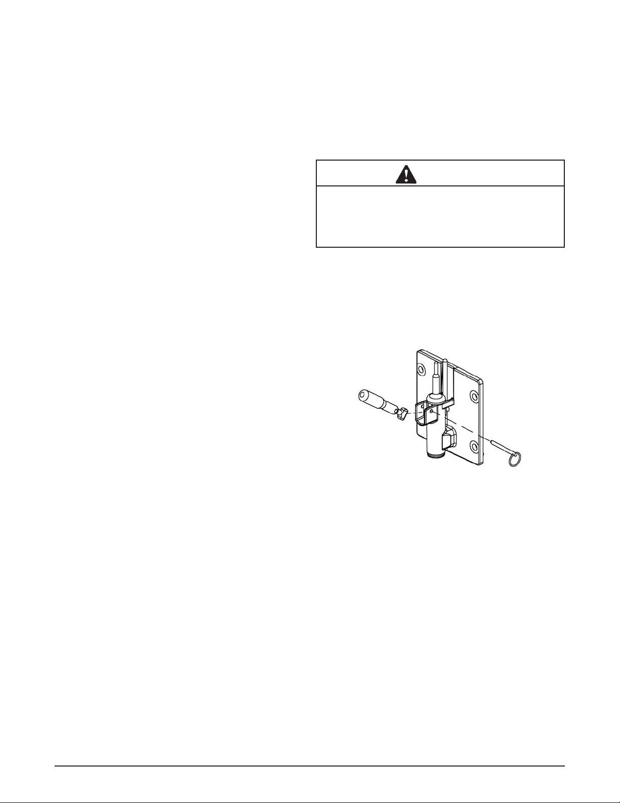
C. EVAPORATOR PRESSURE REGULATOR (EPR)
There is one EPR in the refrigeration system (Refer to
Figure 5-7). It is located on the suction line of the hopper
evaporator and regulates refrigerant pressure.
E. Remove the plastic cap and loosen the locknut
on the EPR. Using a small screwdriver, turn the
adjustment screw counterclockwise 1/2 turn,
then adjust as necessary. Turn the valve stem
clockwise for less cooling or counterclockwise
for more cooling.
F. Allow the system to stabilize for 5 minutes to
ensure pressure remains stable.
EPR REMOVAL
A. Remove the side panel.
B. Recover refrigerant charge per instructions in
Section 5.2.
C. Leave a port open to prevent pressure buildup
during EPR removal.
D. Unsweat the EPR and remove.
EPR REPLACEMENT
To replace the EPR, perform the following procedures:
A. Apply a heat sink (wet cloth) to the EPR.
B. With an open port, braze the EPR into the system
using appropriate brazing material.
C. Remove the heat sink from the hot gas bypass.
D. Replace the fi lter drier. Refer to Section 5.8 for
details.
E. Evacuate and recharge system per instructions
in Section 5.2.
F. Adjust the suction pressure to 60 psig ±2.
D. WATER V ALVE (W ATER COOLED MODELS ONL Y)
The water valve monitors refrigerant pressure and opens
on an increase of pressure. The opening point pressure
is the refrigerant pressure required to lift the valve disc
off the valve seat. (Figure 5-7)
Figure 5-7 EPR Valve
EPR TEST AND ADJUSTMENT
A. Place the CLEAN/OFF/ON switch in the OFF
position.
B. Connect a gauge to the Schrader valve on the
suction line.
C. Place the CLEAN/OFF/ON switch to the ON
position.
D. If the gauge does not read 60 psig ±2 then
adjustment is needed.
Service Manual #513632 26 E112/F112 Model Machines
WATER VALVE ADJUSTMENT
A. Remove the back panel.
B. Connect a gauge to the compressor discharge
Schrader valve.
Figure 5-8 Water Valve
Page 33

C. Take the temperature of the inlet water.
D. Connect the machine to the electrical supply, start
the refrigeration cycle, and read the pressure.
D. Refer to the chart below for correct pressures
and water outlet temperatures:
Inlet Water
Temperature
Discharge
Pressure
Outlet Water
Temperature
60ºF 225-235 psig 81º - 93ºF
70ºF 227-237 psig 83º - 95ºF
80ºF 229-239 psig 84º - 96ºF
90ºF 248-258 psig 90º - 102ºF
100ºF 282-292 psig 100º - 112ºF
110ºF 317-327 psig 109º - 121ºF
Table 5-1 Water Cooled Pressure/Temperature Table
E. If the water temperature is too low, the opening
point pressure should be increased to slow
the water flow. Turn the adjustment screw
counterclockwise.
F. If the water temperature is too high, the opening
point pressure should be decreased to increase
the fl ow of water. Turn the adjustment screw
clockwise.
WATER VALVE REMOVAL
The water valve is connected to the refrigeration system
by capillary tube brazed to the discharge line.
A. Turn off and disconnect the water supply. Blow
out the water lines with compressed air or CO
.
2
B. Recover refrigerant charge per instructions in
Section 5.2.
C. Unsweat the capillary tube from the discharge
line.
E. Remove the clamps from the water lines at the
valve.
F. Remove the two screws holding the water valve
to the frame and remove the valve.
WATER VALVE REPLACEMENT
To replace the water valve, perform the following procedures:
A. Position the water valve and attach to the frame
using the two screws.
B. Install the water lines onto the valve with hose
clamps.
C. Braze the capillary tube into the system using
BCuP-3 or BCuP-5 brazing material.
D. Connect the water supply line and turn on the
water supply.
Figure 5-9 Capillary Tube
E. Check for leaks in the water lines. If there are no
leaks, turn off the water supply.
F. Replace the fi lter drier. Refer to Section 5.8 for
details.
G. Evacuate and recharge system per instructions
in Section 5.2.
H. Turn on the water and check for leaks in the water
lines with the refrigeration system running.
I. Adjust the valve as necessary.
5.7 CAPILLARY TUBE
The capillary tube meters refrigerant fl ow in the hopper
evaporator (Refer to Figure 5-9). The amount of fl ow is
dependent on the length and ID of the capillary tube as
well as the refrigerant charge.
CAPILLARY TUBE REMOVAL
A. Recover refrigerant charge per instructions in
Section 5.2.
B. Leave a port open to prevent pressure buildup
during capillary tube removal.
C. Remove foam insulation from the capillary tube
at the evaporator inlet.
C. Unsweat the capillary tube and remove.
Service Manual #513632 27 E112/F112 Model Machines
Page 34

CAPILLARY TUBE REPLACEMENT
A. Position the capillary tube in place.
B. Apply a heat sink (wet cloth) to the capillary tube
and drier assembly.
C. With an open port, braze the capillary tube into
the system using appropriate brazing material.
D.. Replace foam insulation to the capillary tube at
the evaporator inlet.
E. Evacuate the system per instructions in Section
5.2.
F. Recharge the system per instructions in Section
5.3.
5.8 FILTER DRIER
The fi lter drier must be replaced every time the refrigeration
system is opened for service. A new fi lter drier improves
operation of the entire refrigeration system by stopping
the circulation of moisture and by removing harmful contaminants (Refer to Figure 5-10).
FILTER DRIER REPLACEMENT
A. Position the fi lter drier so the arrow is pointing
towards the evaporators (pointing away from the
condenser).
B. Apply a heat sink (wet cloth) to the fi lter drier.
C. With an open port, braze the fi lter drier into the
system using appropriate brazing material.
D. Evacuate the system per instructions in Section
5.2.
E. Recharge the system per instructions in Section
5.3.
Figure 5-10 Filter Drier
FILTER DRIER REMOVAL
A. Recover refrigerant charge per instructions in
Section 5.2.
B. Cut the refrigeration line as close to the fi lter drier
as possible and remove drier.
C. Cap the ends of the drier using the plugs from
the new drier.
NOTE
The drier must be capped to prevent moisture from
the environment
Service Manual #513632 28 E112/F112 Model Machines
Page 35

SECTION 6
ELECTRICAL AND MECHANICAL CONTROL SYSTEMS
NOTE
The wiring diagrams are located in Section 8.
6.1 CONTROL BOARD
The control board uses a microprocessor to control all
timing and mode operations. It processes information
from the motor and spigot and sends signals to the compressor and motor.
NOTE
The control board is designed for use at 1 15VAC or
208-230VAC. A connector and resistor determine
the voltage setting of the control board. Refer to
Figure 6-1 for the location of the connector and
resistor.
CONTROL BOARD TEST
The following test will show if the control board has proper
voltage.
1. Open the right side panel.
2. When the CLEAN-OFF-ON switch is in the ON
position, read voltage on the control board across
the L1 terminal and one of the neutral terminals
(P2, P3, P4 or P5). Voltage should be near line
voltage (115VAC on E112 and 220VAC on F112).
V oltage Selector
Connector
WARNING
Service to the machine must be completed by
a qualifi ed electrician/refrigeration specialist.
Any tests or work done on the machine must be
done by a qualifi ed technician. Service to the ma-
chine done by an unqualifi ed person, could result
in serious personal injury.
6.2 CONTACTOR
The compressor contactor is mounted behind the right
panel. The control board sends electronic signals to trigger the contactor and start the compressor.
A. CONTACTOR TESTS
The following test will show if the control board is sending
a voltage signal to the contactor.
1. Open the right side panel.
2. When the CLEAN-OFF-ON switch is in the ON
position, read voltage on the control board across
the L1 terminal and one of the neutral terminals
(P2, P3, P4 or P5). Voltage should be near line
voltage (115VAC on E112 and 220VAC on F112).
3. Read voltage on the control board across the L1
terminal and the COMPRESSOR CONTACTOR
terminal during a freezing cycle. Voltage should
be 0V.
The following test will show if a contactor is receiving a
voltage signal from the control board.
1. Open the right side panel.
2. Read voltage across the coils of the contactor
during a freezing cycle. Voltage should be near
line voltage (115VAC on E112 and 220VAC on
F112). If there is no voltage reading, refer to
Section 7 Troubleshooting.
Remove
Resistor for use
at 208-230VAC
Figure 6-1 Control Board
Service Manual #513632 29 E112/F112 Model Machines
Figure 6-2 Contactor
Page 36

6.3 DRIVE MOTOR
The drive motor is used to rotate the auger assembly. An
internal, normally closed, centrifugal switch starts the drive
motor. The motors have an internal thermal overload.
A. DRIVE MOTOR VOLTAGE TEST
The following test will show if the relay on the control
board is working properly and sending a voltage signal
to the drive motor.
1. Open the right side panel.
2. When the CLEAN-OFF-ON switch is in the ON
position, read voltage on the control board across
the L1 terminal and one of the neutral terminals
(P2, P3, P4 or P5). Voltage should be near line
voltage (115VAC on E112 and 220VAC on F112).
3. Read voltage across the L1 terminal and the
AUGER terminal. Voltage should be 0V.
B. DRIVE MOTOR REPLACEMENT
E112 MOTOR REMOVAL
1. Disconnect machine from electrical supply before
removing any panels for servicing.
2. Remove the back panel and the right side panel.
3. Remove the ground wire from the machine frame.
4. Loosen the motor cradle clamps at the front and
back of the motor.
5. Rotate the motor so that the electrical cover plate
can be removed. Remove the cover plate from
the back of the motor.
6. Identify (mark) wires and remove them from the
motor.
7. Remove the belt tension adjustment nut and
remove the belt.
8. Remove the two bolts from the bushing clamp
at the rear of the machine and pull the motor out
through the back of the machine.
9. Remove the bolts that connect the motor to the
mounting plate.
Motor Cradle
Clamps
Belt Tension
Adjustment Nut
Motor Cradle
Clamp
Electrical
Cover Plate
Mounting Bolts
Figure 6-4 E112 Drive Motor
10. Loosen the two allen head screws from the pulley.
11. Remove the pulley and key from the motor shaft.
E112 MOTOR INSTALLATION
1. Place the drive motor on the mounting plate and
install the four mounting bolts.
2. Place the pulley and key on the motor shaft.
NOTE
Do not tighten the pulley screws until after the belt
tension has been properly adjusted.
3. Install the motor and mounting plate in the machine
to the bushing clamp using the mounting bolts.
4. Install the belt and the tension bolt. Tighten the
tension bolt.
5. Use a Burroughs Belt Tension Gauge to set the
tension for the drive belt. Set the E112 belt tension
to 5-15 lbs.
6. Using a straightedge, align the drive motor pulley
with the gearbox pulley. Tighten the two allen
head screws on the drive motor pulley.
7. Loosen the motor cradle clamps at the front and
back of the motor.
8. Rotate the motor so that the electrical cover plate
can be removed. Remove the cover plate from
the back of the motor
9. Install wiring according to the wiring diagram.
Install the electrical cover plate.
10. Tighten the motor cradle clamps.
11. Install back and side panels.
Figure 6-3 E112 Drive Motor
Service Manual #513632 30 E112/F112 Model Machines
Page 37

F112 MOTOR REMOVAL
1. Disconnect machine from electrical supply before
removing any panels for servicing.
2. Remove the back panel and the right side panel.
3. Remove the electrical cover plate from the back
of the motor.
4. Identify (mark) wires and remove them from the
motor.
5. Loosen the belt tension adjustment nut and remove
the belt.
6. Remove the motor mounting bolts.
7. Remove the motor through the back of the
machine.
8. Loosen the two allen head screws from the pulley.
9. Remove the pulley and key from the motor shaft.
F112 MOTOR INSTALLATION
1. Place the pulley and key on the motor shaft.
NOTE
Do not tighten the pulley screws until after the belt
tension has been properly adjusted.
Figure 6-5 Compressor Capacitors
4. Disconnect the bleeder resistor from the circuit.
5. Measure capacitance across the terminals. The
results should be as follows:
Rating
E112 Part MFD VAC
Drive Motor 230440 378-454 MFD 110 VAC
Compressor Start 231058 145-174 MFD 250 VAC
Compressor Run 230648 25 MFD 440 VAC
2. Place the drive motor in position and install the
four mounting bolts.
3. Install the belt and tighten the tension bolt.
4. Use a Burroughs Belt Tension Gauge to set the
tension for the drive belt. Set the F112 belt tension
to 20-30 lbs.
5. Using a straightedge, align the drive motor pulley
with the gearbox pulley. Tighten the two allen
head screws.
6. Install wiring according to wiring diagram. Install
electrical cover plate.
7. Install back and side panels.
6.4 CAPACITORS
The compressor start and run capacitors are mounted
behind the right side panel. The capacitors for the drive
motor are mounted directly onto the motor body. The E112
has one drive motor capacitor. The F112 has two drive
motor capacitors: a run capacitor and a start capacitor.
A. CAPACITOR TEST
1. Place the CLEAN-OFF-ON switch in the OFF
position.
2. Remove a lead from one of the capacitor terminals.
3. Using insulated pliers, discharge the capacitor
with a 20K 5W resistor across the terminals.
NOTE
Discharge the capacitor even if there is a bleeder
resistor across the terminals. There may be an open
in the bleeder resistor preventing it from working
properly.
Rating
F112 Part MFD VAC
Drive Motor Start 231095 500 MFD 125 VAC
Drive Motor Run 231078 50 MFD 370 VAC
Compressor Start 230632 72-86 MFD 330 VAC
Compressor Run 231084 30 MFD 370 VAC
6. Check the resistance across the capacitor
terminals. The reading should be close to 0 and will
rise slowly (as the meter charges the capacitor).
6. If the resistance stops increasing, there may be
an internal short in the capacitor.
7. Discharge the capacitor if the test needs to be
repeated.
B. CAPACITOR REPLACEMENT
1. Place the CLEAN-OFF-ON switch in the OFF
position.
2. Remove leads from the capacitor terminals.
3. Using insulated pliers, discharge the capacitor
with a 20K 5W resistor across the terminals.
NOTE
Discharge the capacitor even if there is a bleeder
resistor across the terminals. There may be an open
in the bleeder resistor preventing it from working
properly
4. Pull the capacitor out of its holder and replace.
5. Connect the leads to the terminals.
Service Manual #513632 31 E112/F112 Model Machines
Page 38

6.5 GEARBOX
A. GEARBOX INSPECTION
Inspect the gearbox and listen for unusual noise. A grinding sound generally indicates a bad gear.
B. GEARBOX REMOVAL
1. Disconnect machine from electrical supply before
removing any panels for servicing.
2. Remove the back panel and the side panel.
3. Remove protective shield from side of machine.
4. Remove the belts.
5. Remove the pulley by loosening the set screws.
6. Remove the three bolts holding the gearbox to
the barrel.
4. Remove the two bolts holding the gearbox to
the mounting bracket and remove the gear box
through the rear of the machine.
C. GEARBOX INSTALLATION
1. Place the gear box in position from the rear of
the machine. Fasten the three bolts through the
gear box to the rear of the barrel.
2. Fasten the gearbox to the mounting bracket using
the two bolts.
3. Mount the pulley on the gear box shaft and align
with the motor pulley, then tighten the allen head
screws.
4. Install the belt.
5. Press fi rmly on the belt.
6. When the tension is properly adjusted, the belt
will depress the approximate width of the belt with
the pressure of a fi nger.
7. If an adjustment is necessary, loosen the four
motor plate retaining nuts, adjust belt tension
then retighten the four nuts.
6.6 CONDENSER FAN MOTOR (AIR-
COOLED ONLY)
A. FAN MOTOR REPLACEMENT
1. Disconnect machine from electrical supply before
removing any panels for servicing.
2. Remove the panels and the header panel as
noted below.
E112: Remove both side panels
F112: Remove the left side panel and rear panel
3. Trace and disconnect the wires on the T1 and
T2 terminals on the compressor contactor. The
F112 has a black and white wire connected to
the contactor. The E112 has two black wires.
4. Remove the four screws on the fan motor bracket
and remove the bracket. Be careful to not damage
the fi ns on the condenser when removing the fan.
Figure 6.6 Fan Motor Replacement
5. Loosen set screw on fan blade.
6. Remove the three bolts from the fan motor
mounting plate and remove the motor.
B. FAN MOTOR INSTALLATION
5. Route the wires to the compressor contactor.
6. Connect the wires to the contactor as follows:
F112: Connect black wire to the T1 terminal.
Connect white wire to the T2 terminal.
E112: Connect a black wire to the T1 terminal and
connect the other black wire to the T2 terminal. It
does not matter which wire is connected to which
terminal.
3. For F112 only: Ensure the purple wire is terminated.
and the ensure red wire is terminated with blue
wire.
1. Attach motor to the mounting plate with the three
bolts.
2. Place fan blade on motor shaft. Make sure the
motor shaft does not extend past the hub of the
fan blade.
7. Install the fan motor bracket to the condenser.
8. Position the fan on the motor shaft so that the
blades are 3/8” from the fi ns on the condenser.
Tighten the set screw.
6.7 SWITCHES
A. SPIGOT SWITCH
The spigot switch is a normally closed, held open switch.
When a spigot is pulled, the spigot switch sends a signal
to the control board to start the drive motor.
SPIGOT SWITCH TESTING - ELECTRICAL
1. Disconnect the switch from the circuit by
unplugging the connector.
Service Manual #513632 32 E112/F112 Model Machines
Page 39

2. Check resistance readings across the common
(COM) and normally closed (NC) terminals.
When the spigot is closed (not dispensing), the
resistance should show an open. When the spigot
is opened (during dispensing), the switch will close
and the resistance should be 0 ohms.
SPIGOT SWITCH REPLACEMENT
1. Remove the header panel.
2. Disconnect the connector from the switch and
remove the switch.
3. Install the replacement switch onto the spigot
assembly.
4. Attach the connector to the spigot switch.
5. Replace the header panel and secure with the
two Phillips head screws.
B. TORQUE SWITCH
The torque switch is a normally open switch. During the
freezing cycle, the product in the freezing cylinder increases consistency. As product consistency increases,
the stator bar rotates and moves the torque rod. When
the torque rod activates the torque switch, the product in
the freezing cylinder is at consistency.
TORQUE SWITCH TEST
1. Disconnect the switch from the circuit by
unplugging the connector.
2. Check resistance readings across the common
(COM) and normally open (NO) terminals. When
the switch is open, the resistance should show an
open. When the switch is closed, the resistance
should be 0 ohms.
TORQUE SWITCH REPLACEMENT
1. Remove the header panel.
2. Disconnect the connector from the switch and
remove the switch.
3. Install the replacement switch onto the torque
assembly.
4. Attach the connector to the torque switch.
5. Replace the header panel and secure with the
two Phillips head screws.
Normally Closed
Held Open
Spigot Switch
Figure 6-7 Spigot Switch
Normally Open
Torque Switch
Figure 6-8 Torque Switch
Service Manual #513632 33 E112/F112 Model Machines
Page 40

Service Manual #513632 34 E112/F112 Model Machines
Page 41

SECTION 7
TROUBLESHOOTING
7.1 LIGHT INDICATORS
The machine has two lights that will alert the user if a problem occurs: an ADD MIX light and a Diagnostic Light.
The ADD MIX light will fl ash to alert the operator to a low mix condition. It does so by monitoring the mix level in the
hopper. When the ADD MIX light is fl ashing, refi ll hopper immediately.
The Diagnostic Light will fl ash if an error occurs. Refer to the chart below for details.
Indication On One Blink Two Blinks Three Blinks
Torque is not
Conditions Defrost Mode
Self
Correction
N/A N/A
met after 20
minutes
(22 minutes for
shake)
Drive current is not sensed
The machine attempts to sense drive
current with a 3 second pre-stir. If
current is sensed, the machine will return
to normal operation. If current is not
sensed, the machine will wait 7 minutes
and try to sense current with another 3
second pre-stir. After the third attempt,
the compressor will run on timers.
Machine left in clean
mode for over 20
minutes
N/A
Operation
Corrective
Action
Every 7 minutes
the auger will
run for 90
seconds.
N/A
Timers or until
torque switch
remains closed
for 3 seconds.
Check for
product in the
hopper, check if
the condenser
is dirty, check
the refrigeration
system.
Timers Off
Check that there is power going to the
contactor, check for power leaving the
contactor, check for power at the motor.
7.2 TROUBLESHOOTING
PROBLEM POSSIBLE CAUSE REMEDY
1 Power to machine is off. 1 Supply power to machine.
Machine does not
run.
Machine will not
shut off before 22
minute Compressor
Time Out Mode.
Product is too fi rm.
2 Blown fuse or tripped circuit. 2 Replace or reset.
3 Freeze-up (auger will not turn). 3 Turn Clean/Off/On switch Off for 15 minutes,
then restart.
4 Front door not in place. 4 Assemble front door in place.
1 Drive belt failure. 1 Replace drive belt.
2 Consistency temperature setting is too
fi rm.
3 Refrigeration problem. 3 Check system.
1 Consistency temperature setting is too
fi rm.
2 Turn Consistency Adjustment knob counter-
clockwise.
1 Turn Consistency Adjustment knob counter-
clockwise.
Turn CLEAN-OFF-
ON switch to OFF
(middle) position then
turn the switch to ON.
Service Manual #513632 35 E112/F112 Model Machines
Page 42

7.2 TROUBLESHOOTING - CONTINUED
PROBLEM POSSIBLE CAUSE REMEDY
Product is too thin.
Product does not
dispense.
Drive belt slipping
or squealing.
Low overrun
Rear auger seal
leaks.
Front door leaks.
1 No vent space for free fl ow of cooling
air.
2 Condenser is dirty. 2 Clean. (See Section 3)
3 Consistency setting too soft. 3 Turn Consistency Adjustment knob clockwise.
4 Auger is assembled incorrectly. 4 Remove mix, clean, reassemble, sanitize and
5 Auto Fill Pump not operating. 5 See Auto Fill Troubleshooting section.
6 Refrigeration problem. 6 Check system.
1 No mix in hopper. 1 See Auto Fill Troubleshooting section.
2 Drive motor overload tripped. 2 Wait for automatic reset.
3 Drive belt failure. 3 Replace drive belt.
4 Freeze-up (Auger will not turn). 4 Turn Clean/Off/On switch Off for 15 minutes,
1 Worn drive belt. 1 Replace drive belt.
2 Freeze-up (Auger will not turn). 2 Turn Clean/Off/On switch Off for 15 minutes,
3 Not tensioned properly. 3 Adjust belt tension
1 Auger is assembled incorrectly. 1 Remove mix, clean, sanitize, and freeze down
2 Mix inlet regulator missing. 2 Replace mix inlet regulator.
3 Mix inlet regulator o-ring missing. 3 Replace mix inlet regulator o-ring.
4 Mix inlet regulator air tube blocked. 4 Clean with sanitized brush.
5 Product breakdown. 5 Fill machine with fresh product.
1 Outside surface of rear auger seal is
lubricated.
2 Rear seal missing or damaged. 2 Check or replace.
3 Seal o-ring missing, damaged or
installed incorrectly.
4 Worn or scratched auger shaft. 4 Replace auger shaft.
1 Front door knobs are loose. 1 Tighten knobs.
2 Spigot parts are not lubricated. 2 See Section 3.
3 Chipped or worn spigot o-rings. 3 Replace o-rings.
4 O-rings or spigot installed wrong. 4 Remove spigot and check o-ring.
5 Inner spigot hole in front door nicked
or scratched.
1 A minimum of 6” of air space on both sides (the
E112 requires 3”). (See Section 2)
freeze down.
then restart.
then restart.
with fresh mix.
1 Clean lubricant from outside of rear seal,
lubricate inside of seal and reinstall.
3 Check. or replace.
5 Replace front door.
Service Manual #513632 36 E112/F112 Model Machines
Page 43

SECTION 8
REPLACEMENT PARTS
8.1 DECALS, LUBRICATION, PANELS & LEGS
Quantity
Part Description E112 F112
208135 Brush - 4” X 8” X 16” (Barrel) 1 1
208380 Brush - 1/4” X 3” X 14” 1 1
208401 Brush - 1” X 3” X 10” 1 1
232091 Cap - Protective (Gray) - #490716 Leg 1
236049 Card - Cleaning Instruction 1 1
324105 Decal - Caution Electrical Shock 1 1
324106 Decal - Caution Electrical Wiring Materials 1 1
324107 Decal - Caution Hazardous Moving Parts 1 1
324141 Decal - Caution Rotating Blades 1 1
324208 Decal - Attention Refrigerant Leak Check 1 1
324393 Decal - Stoelting Swirl Logo 1 1
324509 Decal - Cleaning Instructions 1 1
324548 Decal - Adequate Ventilation 6” 1
324566 Decal - Wired According To 1 1
324584 Decal - Adequate Ventilation 3” 1
324686 Decal - Danger Automatic Start 1 1
324804 Decal - Domed Stoelting Swirl (Header Panel) 1 1
324852 Decal - Clean Condenser Filter 1
324864 Decal - A&W Logo - 324865 Decal - Standby Light 1 1
396244 Gasket - Freezer Base 1
430165 Cord - Power 1
430172 Cord - Power 1
490716 Leg 4
490749 Leg - Front 2
490750 Leg - Rear (w/Suction Cup) 2
508048 Lubricant - Spline (2 oz Squeeze Tube) 1 1
508135 Petrol Gel - 4 oz Tube 1 1
513613 Manual - Owner’s 1 1
649105 Screw - Self-Tapping (E112 - Side Panels) (F112 - All Panels) - 649114 Screw - Header Panel & Bottle Rack 1183955 O-Ring Kit - 2183639 Panel - L.H. Side 1
2183640 Panel - R.H. Side 1
2183641 Panel - Rear (E112 - Ser. #0 - #22767) 1
2183647 Panel - Front (E112 - Ser. #0 - #22767) 1
2183704 Panel - Header 1
2183710 Panel - Bottom 1
2183782 Panel - Electrical Cover (E112 - Ser. #22768 Plus) 1
2183783 Panel - Front (E112 - Ser. #22768 Plus) 1
2183808 Panel - Rear (E112 - Ser. #22768 Plus) 1
2187029 Panel - R.H. Side 1
2187030 Panel - L.H. Side 1
2187036 Panel - Front 1
2187197 Panel - Rear (Air-Cooled) 1
2187241 Panel - Rear (Water-Cooled) 1
2187550 Panel - Front (A & W Only) 7183341 Panel - Electrical Cover (E112 - Ser. #0 - #22767) 1
Service Manual #513632 37 E112/F112 Model Machines
Page 44

8.2 AUGER SHAFT AND FACEPLATE PARTS
624678
666786
F112 - 2187941
E112 - 2187600
2183444
F112 - 2183751
E112 - 2183854
624515
F112 - 2202068
E112 - 2202181
NOTE
The part numbers referenced on this page do
not include all versions of the E1 12 and F1 12.
Refer to page 39 to view the complete listing.
625310
624545
2183099
630053
Service Manual #513632 38 E112/F112 Model Machines
2183739
624644
624645
2183447
336551
570196
2187188
482019
Page 45

8.2 AUGER SHAFT AND FACEPLATE PARTS - CONTINUED
Quantity
Part Description E112 F112
162165 Blade - Scraper (E112 Ser. #22768 - #23376) 2
336546 Door - Front (E112 - Ser. #0 - #23494) 1
336551 Door - Front (E112 - Ser. #23495 Plus) (F112 - All) 1 1
482019 Knob - Front Door (Black) 4 4
570196 Pin - Cotterless Clevis (Front Door) 1 1
624515-5 O-Ring - Stator Bar Rear (5 Pack) 1 1
624545-5 O-Ring - Stator Bar Front (5 Pack) 1 1
624644-5 O-Ring - Spigot Body (Bottom) (5 Pack) 1 1
624645-5 O-Ring - Spigot Body (Top) (5 Pack) 1 1
624678-5 O-Ring - Rear Seal - Black (5 Pack) 1 1
625310 Quad-Ring - Front Door - Black 1 1
630053 Rod - Torque Actuator 1 1
666786 Seal - Rear Auger - Black 1 1
2183099 Breaker Bar - Spigot Body 1 1
2183100 Blade - Scraper (E112 - Ser. #0 - #22767) 2
2183444 Bushing - Stator Support (Rear) 1 1
2183446 Spigot Body (E112 - Ser. #0 - #23197) 1
2183447 Handle Only - Spigot 1 1
2183449 Bushing - Front Auger Support (F112 - Ser. #0 - #25280) 1
2183645 Rod Actuator - Spigot (E112 - Ser. #0 - #22767) 1
2183739 Spigot Body (E112 - Ser. #23198 Plus) (F112 - All) 1 1
2183751 Blade - Scraper 1
2183854 Blade - Scraper (E112 - Ser. #23377 Plus) 1
2187188 Bushing - Front Auger Support (E112 - All) (F112 - Ser. #25281 Plus) 1 1
2187225 Auger Shaft (F112 - Ser. #0 - #25280) 1
2187600 Auger Shaft 1
2187941 Auger Shaft 1
2202068 Stator Bar 1
2202181 Stator Bar 1
Service Manual #513632 39 E112/F112 Model Machines
Page 46

8.3 HOPPER PARTS
E112 - 2183642
F112 - 2183721
624607
314466
417006
744281
744254
600082
194024
Quantity
Part Description E112 F112
194024 Bottle - Flavor (Plastic) - 314466 Cover - Hopper (E112 - Non LJS) (F112 - Non Auto Fill) 1 1
417006 Grid - Drip Tray (Metal) 1 1
600082 Pump - Flavor (Plastic Bottle) - 624607-5 O-Ring - Mix Inlet (5 Pack) 2 2
744254 Tray - Drip (E112 - Ser. #24587 Plus) (F112 - All) 1 1
744273 Tray - Drip (E112 - Ser. #0 - #24586) 1
744281 Tray - Drain (Front) 1 1
744601 Tray - Drain (Rear) 1
2177315 Cover - Hopper (E112 - LJS) (F112 - Auto Fill Kit) - 2177316 Clip - Retaining (Mix Inlet) (Auto Fill Kit) 2177317 Mix Inlet Assembly (Auto Fill Kit) 2183642 Mix Inlet Assembly 1
2183721 Mix Inlet Assembly 1
2187039 Rack - Flavor Bottle (F112) 2187041 Rack - Flavor Bottle (E112) 2187918 Mix Inlet Assembly (LJS) 2187919 Clip - Retaining (Mix Inlet) (LJS) -
Service Manual #513632 40 E112/F112 Model Machines
Page 47

8.4 MACHINE FRONT & SPIGOT SWITCH ASSEMBLY
493048
482004
493046
718165
718773
694334
2183731
695706
695707
718013
Quantity
Part Description E112 F112
482004 Knob (Consistency Adjustment) 1 1
493046 Light - Mix Low 1 1
493048 Light - Diagnostic (Round) 1 1
493057 Light - Diagnostic (Rectangular) 1 1
493080 Light - Mix Out (Rectangular) 1
694334 Spring - Compression (Spigot Switch) 1 1
695706 Spring - Consistency Adjustment (Green) 1
695707 Spring - Consistency Adjustment (Yellow) 1 (shake) 1
695714 Spring - Consistency Adjustment (Red) 1 (shake)
718013 Switch - Roller (Spigot) 1 1
718165 Switch - Rocker (Clean-Off-On) 1 1
718773 Switch - Limit (Torque Consistency) 1 1
2183459 Actuator - Spigot Switch (E112 - Ser. #0 - #23197) 1
2183731 Actuator - Spigot Switch (E112 - Ser. #23198 Plus) 1
2183851 Bracket - Drip Tray (E112 - Ser. #23377 Plus) (F112 - All) 1 1
7183303 Bracket - Drip Tray (E112 - Ser. #0 - #24586) 1
695714
Service Manual #513632 41 E112/F112 Model Machines
Page 48

8.5 E112 PARTS
521696.3-115
2202177
618180
719111
522308
230648
231058
152232
295019
718794
762978
598155
598026
522720
231108
357095
2183792
614222
762479
342006
458003
284089
282054
Service Manual #513632 42 E112/F112 Model Machines
Page 49

8.5 E112 PARTS - CONTINUED
Part Description E112 Qty.
152232 Belt - Grip-Notch (AX26) (E112 - Ser. #23377 Plus) 1
152233 Belt - Grip-Notch (AX28) (E112 - Ser. #0 - #23376) 1
230440 Capacitor (#522233 Drive Motor) 1
230648 Capacitor - Run (Compressor) 1
231058 Capacitor - Start (Compressor) 1
231101 Cap Tube Only (E112 - Ser. #0 - #23197) 1
231108 Cap Tube Only (E112 - Ser. #23198 Plus) 1
266196 Pin - Parts Safety (LJS) 282054 Compressor (No Capacitors) 1
284088 Condenser - Air-Cooled (E112 - Ser. #0 - #22767) 1
284089 Condenser - Air-Cooled (E112 - Ser. #22768 Plus) 1
295019 Contactor (45CG20AF) 1
342006 Drier 1
357093 Blade - Fan (Air-Cooled Condenser) (E112 - Ser. #0 - #23197) 1
357095 Blade - Fan (Air-Cooled Condenser) (E112 - Ser. #23198 Plus) 1
368397 Filter (2 Required) 2
458003 Indicator - Liquid Line 1
521696.3-115 Program Control Board (Use #2202177 if #295019 Contactor
Not Installed) 1
522233 Motor - Drive - 1/2 HP (E112 - Ser. #0 - #23376) 1
522308 Fan Motor - Condenser 1
522720 Motor - Drive - 1/3 HP (E112 - Ser. #23377 Plus) 1
598026 Pulley - Drive Motor (E112 - Ser. #23377 Plus) 1
598027 Pulley - Drive Motor (E112 - Ser. #0 - #23376) 1
598155 Pulley - Speed Reducer 1
614222 Speed Reducer 1
618180 Relay (Compressor) 1
649200 Spring - Door Interlock 1
718537 Switch - Limit (Door Interlock) (E112 - Ser. #0 - #23494) 1
718794 Switch - High Pressure Reset 1
719111 Switch - Limit (Door Interlock) (E112 - Ser. #23495 Plus) 1
756067 Tubing - 1/4” ID (LJS) (Per Inch) (Auto Fill Kit) 762479 Valve - Expansion 1
762978 Valve - EPR 1
763664 Valve - Solenoid (LJS) (Auto Fill Kit) 1170836-SV Switch Assembly - Limit (Door Interlock) (E112 - Ser. #0 - #23494) 1
2183792 Evaporator Assembly (E112 - Ser. #22768 Plus) 1
2202177 Program Control Board Kit (Use #521696.3-115 if #295019
Contactor Installed) 7183311 Evaporator Assembly (E112 - Ser. #0 - #22767) 1
Service Manual #513632 43 E112/F112 Model Machines
Page 50

8.6 F112 PARTS
2183709
521696.3-230
2202178
762482
458003
744142
231084
230632
618157
231108
614222
762978
295017
598296
152237
342006
694200
282092
719111
598540
718794
522858
162077
284084
522291
Service Manual #513632 44 E112/F112 Model Machines
Page 51

8.6 F112 PARTS - CONTINUED
Part Description F112 Qty.
152237 Belt - Grip-Notch (AX35) 1
162077 Blade - Fan (Air-Cooled Condenser) 1
230632 Capacitor - Start (#282045 Compressor) 1
231027 Capacitor - Run (#282052 Compressor) 1
231042 Capacitor - Start (#282052 Compressor) 1
231078 Capacitor - Run (#522858 Motor) 1
231084 Capacitor - Run (#282045 Compressor) 1
231095 Capacitor - Start (#522858 Motor) 1
231108 Cap Tube Only 1
264235 Clamp - Metal (1/4” I.D. Tubing) (Auto Fill Kit) 282052 Compressor - 50 Hz - R404A (No Capacitors) 282092 Compressor - 60 Hz - R404A (No Capacitors) 1
284084 Condenser (Air-Cooled) 1
284104 Condenser (Water-Cooled) 1
295017 Contactor (45CG20AG) 1
342006 Drier 1
368140 Filter - Air (Condenser) 1
458003 Indicator - Liquid Line 1
521696.3-230 Program Control Board (Use #2202178 if #295017 Contactor
Not Installed) 1
522291 Motor - Fan 1
522858 Motor - Drive 1
598296 Pulley - Speed Reducer 1
598540 Pulley - Drive Motor 1
614222 Speed Reducer 1
618142 Relay - Start (#282052 Compressor) 618157 Relay - Start (#282045 Compressor) 1
694200 Spring - Door Interlock 1
718794 Switch - High Pressure Reset 1
719111 Switch - Limit (Door Interlock) 1
744142 Transformer (Auto Fill Kit) 756067 Tubing - 1/4” ID (Auto Fill Kit) 762482 Valve - Expansion 1
762978 Valve - EPR 1
763181 Valve - Water 1
763458 Valve - Solenoid (Auto Fill Kit) 2183709 Evaporator Assembly (Non A & W) 1
2187430 Kit - Side Mounting Rack (A&W Only) 2187546 Evaporator Assembly (A&W Only) 2202178 Program Control Board Kit (Use #521696.3-230 if #295017
Contactor Installed) -
Service Manual #513632 45 E112/F112 Model Machines
Page 52

8.7 RETROFIT KITS
The E112 and F112 retrofi t kits have a redesigned torque switch bracket. The kits also replace the consistency ad-
justment knob with an adjustment screw.
Note: If the machine has been retrofi tted, there will not be a consistency adjustment knob visible from the front of
the machine.
Following are the parts required for the retrofi t kit:
E112 (SER. #0 - #22767)
Part Description Quantity
630053 Rod - Torque Actuator 1
2183739 Spigot Body 1
2187512 Kit - Header Panel Retrofi t 1
2187557 Stator Bar 1
E112 (SER. #22768 - #23197)
Part Description Quantity
2183739 Spigot Body 1
2187512 Kit - Header Panel Retrofi t 1
2187557 Stator Bar 1
E112 (SER. #23198 - #25947)
Part Description Quantity
2187512 Kit - Header Panel Retrofi t 1
F112 (SER. #0 - #25501)
Part Description Quantity
2187513 Kit - Header Panel Retrofi t 1
2187556 Stator Bar 1
Service Manual #513632 46 E112/F112 Model Machines
Page 53

8.8 REFRIGERATION DIAGRAM
!
"
##
$#
##
!
"
##
$#
##
E112 Refrigeration Diagram
F112 Refrigeration Diagram
Service Manual #513632 47 E112/F112 Model Machines
Page 54

8.9 E112 WIRING DIAGRAM
Service Manual #513632 48 E112/F112 Model Machines
Page 55

Service Manual #513632 49 E112/F112 Model Machines
Page 56

8.10 F112 WIRING DIAGRAM
Service Manual #513632 50 E112/F112 Model Machines
Page 57

Service Manual #513632 51 E112/F112 Model Machines
Page 58

8.11 AUT OFILL OPTIONS
The E112 and F112 machines can easily be confi gured
to use an Autofi ll System. The Autofi ll System provides a
constant supply of non-dairy mix to the machine.
AUTOFILL KIT
An autofi ll kit is needed to use an Autofi ll System. The
kit includes a solenoid, tubing, and a new hopper cover
(the F112 also includes a transformer). See below for the
Autofi ll Kit part numbers.
AUTOFILL SYSTEMS
There are two Autofi ll Systems available: the Fill-O-Matic
II and the Fill-O-Matic III. See below for details on the
Autofi ll Systems.
Fill-O-Matic II
The Fill-O-Matic II is powered through an electrical outlet
and pumps up to 60 gallons per hour.
Fill-O-Matic III
The Fill-O-Matic III is powered by gas and pumps up to
45 gallons per hour.
Fill-O-Matic II & Fill-O-Matic III
Fill-O-Matic II
Part Numbers Autofi ll System: 4177349
E112 Autofi ll Kit: 2183807
F112 Autofi ll Kit: 2187101
Usage For use with non-potentially hazardous food substances; non-dairy
Dimensions L 11-1/2” x W 11-1/2” x H 32-1/2”
Electrical 115VAC 60Hz
15A power cord provided
Mix Storage 15 gallon plastic tank
Clean Process Removable strainer allows for easy cleaning
Output Pumps up to 60 gallons per hour
Fill-O-Matic III
Part Numbers Autofi ll System: 4177370
E112 Autofi ll Kit: 2183807
F112 Autofi ll Kit: 2187101
Usage For use with non-potentially hazardous food substances; non-dairy
Dimensions L 11-1/2” x W 11-1/2” x H 27-1/2”
Electrical No electrical connections required
Powered by CO
Mix Storage 15 gallon plastic tank
Clean Process Clean-in-place by pumping solution through hoses
Output Pumps up to 45 gallons per hour
, Nitrogen or compressed air
2
Service Manual #513632 52 E112/F112 Model Machines
Page 59

DOMESTIC WARRANTY
(Including Mexico)
SOFT SERVE / SHAKE EQUIPMENT
1. Scope:
PW Stoelting, L.L.C. (“Stoelting”) warrants to the first user (the “Buyer”) that the freezing cylinders,
hoppers, compressors, drive motors, speed reducers, and augers of Stoelting soft serve / shake
equipment will be free from defects in materials and workmanship under normal use and proper
maintenance appearing within five (5) years, and that all other components of such equipment
manufactured by Stoelting will be free from defects in material and workmanship under normal use
and proper maintenance appearing within twelve (12) months after the date that such equipment is
originally installed.
2. Disclaimer of Other Warranties:
THIS WARRANTY IS EXCLUSIVE; AND STOELTING HEREBY DISCLAIMS ANY
IMPLIED WARRANTY OF MERCHANTABILITY OR FITNESS FOR PARTICULAR
PURPOSE.
3. Remedies:
Stoelting’s sole obligations, and Buyer’s sole remedies, for any breach of this warranty shall be the
repair or (at Stoelting’s option) replacement of the affected component at Stoelting’s plant in Kiel,
Wisconsin, or (again, at Stoelting’s option) refund of the purchase price of the affected equipment,
and, during the first twelve (12) months of the warranty period, deinstallation/reinstallation of the
affected component from/into the equipment. Those obligations/remedies are subject to the
conditions that Buyer (a) signs and returns to Stoelting, upon installation, the Start-Up and Training
Checklist for the affected equipment, (b) gives Stoelting prompt written notice of any claimed breach
of warranty within the applicable warranty period, and (c) delivers the affected equipment to Stoelting
or its designated service location, in its original packaging/crating, also within that period. Buyer shall
bear the cost and risk of shipping to and from Stoelting’s plant or designated service location.
4. Exclusions and Limitations:
This warranty does not extend to parts, sometimes called “wear parts”, which are generally expected
to deteriorate and to require replacement as equipment is used, including as examples but not
intended to be limited to o-rings, auger flights, auger seals, auger support bushings, and drive belts.
All such parts are sold
AS IS.
Further, Stoelting shall not be responsible to provide any remedy under this warranty with respect to
any component that fails by reason of negligence, abnormal use, misuse or abuse, use with parts or
equipment not manufactured or supplied by Stoelting, or damage in transit.
THE REMEDIES SET FORTH IN THIS WARRANTY SHALL BE THE SOLE LIABILITY
STOELTING AND THE EXCLUSIVE REMEDY OF BUYER WITH RESPECT TO
EQUIPMENT SUPPLIED BY STOELTING; AND IN NO EVENT SHALL STOELTING
BE LIABLE FOR ANY INCIDENTAL OR CONSEQUENTIAL DAMAGES, WHETHER
FOR BREACH OF WARRANTY OR OTHER CONTRACT BREACH, NEGLIGENCE OR
OTHER TORT, OR ON ANY STRICT LIABILITY THEORY.
SFWARR-013
Revision 04
Page 1 of 1
 Loading...