

Page 1

Model E157/E257/F257
Owner's Manual
Manual No. 513563 Jul. 2003, Rev. 2
Page 2

Page 3
Need Part s or Service?
We stock the parts you need.
Our Technicians are factory
trained and are certified in the
Stoelting Technicare program.
CALL
Distributor: _________________________
Phone No.: _________________________
(fill in or affix label)
Model No.: _______________________
Serial No.: _______________________
Purchase Date: ____________________
Start-Up Date:____________________
Page 4

Page 5

OWNER'S MANUAL
MODELS E157/E257/F257
SLUSH FREEZERS
This manual provides basic information about the freezer and its components. Instructions and
suggestions are given covering its basic operation and care.
The illustrations and specifications are not binding in detail. We reserve the right to make changes
at any time without notice, to the freezer and its components, without incurring any obligation to equip
same on freezer components built prior to date of change.
DO NOT ATTEMPT to operate the freezer until instructions and safety precautions in the manual are
read completely and thoroughly understood. The freezer should be operated by only qualified
personnel. If problems develop or arise in connection with installation, operation or servicing of the
freezer, contact your local Stoelting Distributor.
Stoelting, LLC Tele: 920-894-2293
502 Hwy. 67
Kiel, WI 53042-1600 Fax: 920-894-7029
Page 6

Page 7

TABLE OF CONTENTS
SECTION 1 - INTRODUCTION ............................................................................................1
1.1 Description ......................................................................................................................1
1.2 Specifications ..................................................................................................................1
SECTION 2 - INSTALLATION INSTRUCTIONS ..................................................................3
2.1 Safety Precautions ...........................................................................................................3
2.2 Shipment and T ransit........................................................................................................3
2.3 Freezer Installation ........................................................................................................... 3
2.4 Adjusting Cup Dispensers................................................................................................7
SECTION 3 - INITIAL SET-UP AND OPERATION............................................................... 9
3.1 Operator's Safety Precautions..........................................................................................9
3.2 Operating Controls and Indicators ....................................................................................9
3.3 Draining The Freezer For Disassembling and Cleaning....................................................10
3.4 Disassembly and Cleaning of Freezer Parts.....................................................................10
3.5 Sanitizing The Freezers and Freezer Parts.......................................................................15
3.6 Assembly of Freezer ........................................................................................................ 15
3.7 Mix Information .................................................................................................................17
3.8 Freeze Down and Operation ............................................................................................17
3.9 Dispensing Product..........................................................................................................17
3.10 Routine Cleaning............................................................................................................17
3.1 1 Preventative Maintenance...............................................................................................17
3.12 Extended Storage ..........................................................................................................18
SECTION 4 - REPLACEMENT PARTS & REFERENCE DRAWINGS............................... 21
4.1 How to Order Decals and T ags.........................................................................................21
4.2 Exploded Views and Parts Lists (E157, E257, F257).......................................................22
ADDENDUM - FILL-O-MA TIC............................................................................................ 29
Page 8

LIST OF ILLUSTRATIONS
Figure Title Page
1 Model E157 - Front......................................................................................................................... 2
2 Model E157 - Side.......................................................................................................................... 2
3 Model E257/F257 - Front................................................................................................................ 2
4 Model E257/F257 - Side................................................................................................................. 2
5 Adjustable Leg ............................................................................................................................... 3
6 Warning Label Locations - E157..................................................................................................... 4
7 Warning Label Locations - E257/F257 ............................................................................................ 5
8 Space & Ventilation Requirements ................................................................................................. 6
9 Electrical Plug................................................................................................................................ 6
10 Installing Sani-tray and Cover ......................................................................................................... 6
11 Adjusting Cup Dispensers .............................................................................................................. 7
12 Operating Controls ......................................................................................................................... 9
13 Removing Sani-tray and Cover ........................................................................................................ 11
14 Draining Product............................................................................................................................. 11
15 Removing Spigot Assembly............................................................................................................ 12
16 Removing Spigot O-Ring from Spigot Body..................................................................................... 12
17 Cut-away View of Spigot Assembly ................................................................................................ 12
18 Removing Drive Cap and O-Ring ..................................................................................................... 13
19 Removing Sealer Ring .................................................................................................................... 13
20 Removing Agitator Assembly and Lower Bushing ........................................................................... 13
21 Removing Divider Plate from Agitator Fingers ................................................................................. 14
22 Removing Drive Shaft...................................................................................................................... 14
23 Exploded View of Divider Plate and Agitator Assembly................................................................... 14
24 Lubricating Drive Shaft.................................................................................................................... 15
25 Installing Divider Plate and Agitator Assembly................................................................................16
26 Proper Installation of Sealer Ring.................................................................................................... 16
27 Correct and Incorrect Alignment of Vertical Center Post Guide Hole............................................... 16
28 External Parts To Be Cleaned ........................................................................................................ 19
Page 9

SECTION 1
INTRODUCTION
1.1 DESCRIPTION
Models E157/E257F257 freezers are gravity fed. The
freezers are equipped with fully automatic controls to
provide a uniform product. The freezers are designed to
operate with most neutral bases and concentrated flavors.
1.2 SPECIFICATIONS
This manual is designed to assist qualified service personnel and operators in the installation, operation and maintenance of the Models E157/E257/F257 freezers.
DIMENSI ONS
WEIGHT
ELECTRICAL
COMPRESSOR
COOLING
E157 COUNTER
MODEL FREEZER
width: 15" (38.1 cm)
depth: 29. 5" ( 74.8 cm)
height: 34 .75" ( 88. 3 cm)
130 lbs. (58.9 kg) 140 lbs. (63 .5 kg ) 140 lbs. (63.5 kg)
1 Phase, 115 VAC*
1/12 HP Drive Motor
2500 BTUH**
(frozen product output)
- Approx. 11 total running
amps. Use 15 Amp circui t break er
Air cooled requires minimum
3" (7.6 cm) air clear a nce on
sides and 1" (2.5 cm) at rear
of unit.
E257 FLOO R
MODEL FREEZER
w idth: 15" (38.1 cm)
depth: 1 9.25 " (4 8.9 cm)
height: 61.38" (156 cm)
1 Phase, 115 VAC*
1/12 HP Drive Motor
2500 BTUH**
(frozen product output)
- Approx. 11 total running
amps. Use 15 Am p circuit brea ker
Requires unobstructed front
and 6" minimum (15.2 cm)
clearance a t back of un it. No
clearance n eeded on side of
unit.
F257 FLOOR
MODEL FREEZER
width: 15" (38.1 cm)
depth: 19 .25" (48 .9 c m)
height: 61 .38" (156 cm)
1 Phase, 115 VAC*
1/12 HP Drive Motor
5200 BTUH**
(frozen product output)
- Approx. 9 total running
amps. Use 15 Amp cirucit breaker
Requires unobstructed front
and 6" minimum (15.2 cm)
clearance at back of unit. No
clearance need ed o n side of
unit.
HOPPER
10 gallons (37. 9 liters) 10 gallons ( 37.9 liters) 10 gallons (37. 9 liter s)
* A transformer is requi red i f voltage i s over 126.5 volts or under 103 volts.
** Unde r normal oper ati n g co ndi t i ons .
1
Page 10

Figure 1
Model E157 - Front
Figure 2
Model E157 - Side
Figure 3
Model E257/F257 - Front
NOTE: Figures in parenthesis are in centimeters.
Figure 4
Model E257/F257 - Side
2
Page 11
SECTION 2
INSTALLATION INSTRUCTIONS
2.1 SAFETY PRECAUTIONS
Do not attempt to operate the freezer until the safety
precautions and operating instructions in this manual are
read and completely understood.
Take notice of all warning labels on the freezer (Figures 6
& 7). The labels have been put there to help maintain a safe
working environment. The labels have been designed to
withstand washing and cleaning. All labels must remain
legible for the life of the freezer. Labels should be checked
periodically to be sure they can be recognized as warning
labels.
If danger, warning, or caution labels are needed, indicate
the part number, type of label, location of label, and
quantity required along with your address and advise your
distributor.
2.2 SHIPMENT AND TRANSIT
The freezer has been assembled, operated and
inspected at the factory. Upon arrival at the final destination, the complete freezer must be checked for any
damage which may have occurred during transit.
With the method of packaging used, the freezer should
arrive in excellent condition. THE CARRIER IS
RESPONSIBLE FOR ALL DAMAGE IN TRANSIT,
WHETHER VISIBLE OR CONCEALED.
NOTE
Accurate leveling is necessary for correct
drainage of freezer barrel and to insure proper
operation.
C. The counter model freezer must be placed on a solid
level surface. Place the rubber pad furnished under the
freezer to create a seal to that surface. The counter
model freezer is air-cooled and discharges at the top.
AL LOUVERED PANELS MUST have 3" of clearance
on sides of unit, 10" of clearance at the top, and 1"
clearance at rear of unit for proper cooling.
Do not pay the freight bill until the freezer has been
checked for damage. Have the carrier note any visible
damage on the freight bill. If concealed damage and/or
shortage is found later, advise the carrier within 10 days
and request inspection. The customer must place claim
for damages and/or shortages in shipment with the carrier.
2.3 FREEZER INSTALLATION
Installation of the freezer involves moving the freezer close
to its permanent location, removing all crating, setting in
place, assembling parts, and cleaning.
A. Uncrate the freezer.
B. The floor model freezers must be placed in a
solid level position. To level the freezer, turn the bottom
part of each leg in or out. Place a level on top of the
hopper, with the cover removed, to check whether or not
the freezer islevel (Fig. 5).
Figure 5
Adjustable Leg
3
Page 12

IMPORTANT NOTICE TO OPERATOR
BEFORE INSTALLING EQUIPMENT, READ THE OWNER'S MANUAL CAREFULLY. TAKE NOTE OF ALL INSTRUCTIONS AND CAUTION
DECALS ON THIS EQUIPMENT.
GO OVER THE MANUAL THOROUGHLY AND POINT OUT ALL DECALS TO YOUR EMPLOYEES, SO THEY UNDERSTAND HOW TO SAFELY
OPERATE THIS EQUIPMENT.
DO NOT REMOVE, DEFACE, OR PAINT OVER ANY DECALS. THEY ARE THERE FOR YOUR SAFETY.
CAUTION
THIS DEVICE MUST BE PLUGGED INTO
A GROUNDED RECEPTACLE TO
PREVENT SHOCK HAZARD.
324113
(Behind Sani-tray)
CAUTION
HAZARDOUS MOVING PARTS
DO NOT OPERATE UNIT WITH OUTER
COVERING REMOVED.
S24107
CAUTION
THIS DEVICE MUST BE PLUGGED INTO A PROPERLY GROUNDED
RECEPTACLE TO PREVENT ELECTRICAL SHOCK HAZARD.
TAMPERING WITH THE PLUG OR USING VOLTAGES OTHER THAN
THE SPECIFICATIONS ON I.D. PLATE WILL VOID YOUR WARRANTY.
REFER TO OWNER'S MANUAL FOR INSTALLATION
INSTRUCTIONS.
723529
Warning Label Locations - E157
(Behind Sani-tray)
DANGER
ELECTRONIC SHOCK HAZARD
DISCONNECT FROM THE SOUCE OF
ELECTRICAL SUPPLY IN BUILDING
BEFORE SERICING UNIT
321105
Figure 6
4
Page 13

IMPORTANT NOTICE TO OPERATOR
BEFORE INSTALLING EQUIPMENT, READ THE OWNER'S MANUAL CAREFULLY. TAKE NOTE OF ALL INSTRUCTIONS AND CAUTION
DECALS ON THIS EQUIPMENT.
GO OVER THE MANUAL THOROUGHLY AND POINT OUT ALL DECALS TO YOUR EMPLOYEES, SO THEY UNDERSTAND HOW TO SAFELY
OPERATE THIS EQUIPMENT.
DO NOT REMOVE, DEFACE, OR PAINT OVER ANY DECALS. THEY ARE THERE FOR YOUR SAFETY.
(Affixed to condenser shroud)
CAUTION
HAZARDOUS MOVING PARTS
DO NOT OPERATE UNIT WITH OUTER
COVERING REMOVED
324107
CAUTION
THIS DEVICE MUST BE PLUGGED INTO
A GROUNDED RECEPTACLE TO
PREVENT SHOCK HAZARD.
324113
THIS DEVICE MUST BE PLUGGED INTO A PROPERLY
GROUNDED RECEPTACLE TO PREVENT ELECTRICAL
SHOCK HAZARD.
TAMPERING WITH THE PLUG OR USING VOLTAGES OTHER
THAN THE SPECIFICATIONS ON I.D. PLATE WILL VOID
YOUR WARRANTY.
REFER TO OWNER'S MANUAL FOR INSTALLATION
INSTRUCTIONS.
723529
CAUTION
Warning Label Locations - E257/F257
Figure 7
(Affixed to condenser shroud)
DANGER
ELECTRONIC SHOCK HAZARD
DISCONNECT FROM THE SOUCE OF
ELECTRICAL SUPPLY IN BUILDING
BEFORE SERICING UNIT
321105
5
Page 14

D. The floor model freezers are equipped with air-cooled
condensers and require correct ventilation. The front of
the freezer is the air intake and must be unobstructed.
Air discharges out of the rear of the unit. Do not obstruct
the discharge. Allow a 6" (15.2 cm) clearance behind
the unit (Fig. 8).
CAUTION
FAILURE TO PROVIDE ADEQUATE VENTILATION WILL
VOID WARRANTY!
CAUTION
DO NOT ALTER OR DEFORM PLUG IN ANY WAY!
Figure 9
Electrical Plug
G. Install the drip tray support, drip tray, drip tray grid,
cover and miscellaneous parts on the freezer. (Fig. 10)
Figure 8
Space and Ventilation Requirements
E. Place the ON-OFF-STIR ONLY toggle switch in the
OFF position. This switch is located on the lower left of
the freezer, under the drip tray and cover.
F. Connect the power cord. The plug is designed for 115
volt/15 amp duty. The unit must be connected to a
properly grounded receptacle. The electrical cord
furnished as part of the freezer has a three prong
grounding type plug (Fig.9). The use of an extension
cord is not recommended. If one must be used, use one
with a wire, size 12 gauge or heavier, with a ground. Do
not use an adaptor to avoid grounding equipment.
Figure 10
Installing Drip Tray and Cover
6
Page 15

2.4 ADJUSTING CUP DISPENSERS
To adjust the cup dispensers, install the size cup desired
into the dispenser and turn the wing nuts on the dispenser
mounting bracket until enough tension is applied to the rim
of the cup to keep it from dropping out (Fig. 11). Do not overtighten the wing nuts.
WING NUTS
Figure 11
Adjusting Cup Dispensers
7
Page 16

8
Page 17

SECTION 3
INITIAL SET-UP AND OPERATION
3.1 OPERATOR'S SAFETY PRECAUTIONS
A. Know the freezer. Read and understand the Operating
Instructions.
B. Notice all warning labels on the freezer.
C. Wear proper clothing. Avoid loose fitting garments,
and remove watches, rings or jewelry which could
cause a serious accident.
D. Maintain a clean work area. Avoid accidents by
cleaning up the area and keeping it clean.
E. Stay alert at all times. Know which switch, push-
button or control you are about to use and what
effect it is going to have.
F. Disconnect electrical cord for maintenance. Never
attempt to repair or perform maintenance on the
freezer until the main electrical power has been
disconnected.
G. Do not operate under unsafe operating conditions.
Never operate the freezer if unusual or excessive
noise or vibration occurs.
3.2 OPERATING CONTROLS AND INDICATORS
Before operating the freezer, it is required that the operator
know the function of each operating control and indicator.
Refer to Figure 12 for the locations of the operating controls
and indicators.
WARNING
THE STIRRING ONLY-OFF-STIRRING & FREEZING
SWITCH MUST BE PLACED IN THE OFF POSITION
WHEN DISASSEMBLING FOR CLEANING OR SERVICING. THE FREEZER MUST BE DISCONNECTED FROM
ELECTRICAL SUPPLY BEFORE REMOVING ANY ACCESS PANELS. ONLY A QUALIFIED SERVICE TECHNICIAN MAY REMOVE ACCESS PANELS.
STIRRING ONLY-OFFSTIRRING & FREEZING
TOGGLE SWITCH
RESET
SWITCH
24-HOUR TIMER
Figure 12
Operating Controls
9
HIGH PRESSURE MANUAL
RESET SWITCH
Page 18

A. STIRRING ONLY-OFF-STIRRING & FREEZING
SWITCH
The STIRRING ONLY-OFF-STIRRING & FREEZING switch is a three-position toggle switch used to
control the operation of the refrigeration system and
agitator. When the switch is placed in the STIRRING ONLY position, the refrigeration system will
be off and the agitator will rotate for cleaning, or if
stirring is required when the store is closed. When the
switch is placed in the OFF position, the refrigeration
system and agitator will be off. The switch should be
placed in the STIRRING & FREEZING position for
normal operation.
B. RESET SWITCH
The reset switch is a two-position breaker switch. This
switch is used to protect the freezer from mechanical
damage. The switch must be in the NORMAL
OPERATING POSITION (up) before the freezer will
operate.
Any time a condition occurs which causes the
agitator drive motor to draw excessive current, the
reset switch will automatically switch to the
OVERLOAD CUT-OUT FREEZER NOT OPERATING position. This will shut down the freezing and
agitation action of the freezer to protect the agitator
drive motor from burning out.
Should the reset switch ever trip out, move
the STIRRING ONLY-OFF-STIRRING & FREEZING toggle switch to the STIRRING ONLY position.
Then move the reset switch back to NORMAL
OPERATING POSITION (up) and allow the freezer
to stir, without refrigeration, for five minutes. After
five minutes of stirring, return the STIRRING
ONLY-OFF-STIRRING & FREEZING switch to the
STIRRING & FREEZING position.
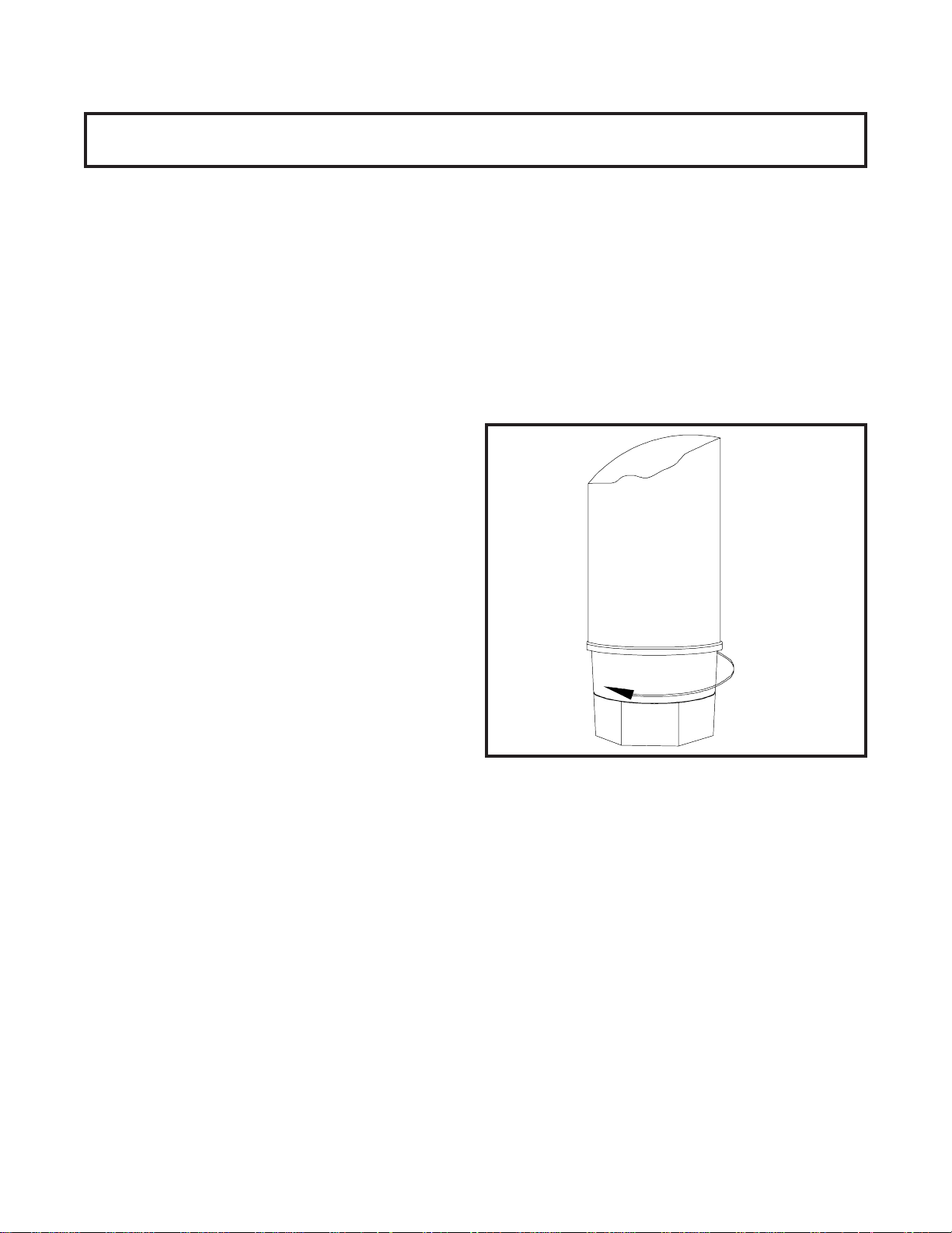
C. 24 HOUR TIMER
To program the timer, rotate program disc in the
direction of the arrows to align the correct day/time
with the time of day mark. Then pull out for Off time
or push in for On time. Each actuator is equivalent
to 15 minutes time. Check for AM/PM centered
between 12 and 12 on rotating disc. At a 6:00 setting the
indicator will point to AM or PM.
D. HIGH PRESSURE MANUAL RESET SWITCH
The HIGH PRESSURE MANUAL RESET SWITCH is a
safety switch designed to protect the compressor from
damage due to excessive head pressure. When tripped,
the lever will be out; push to reset.
E. SPIGOT ASSEMBLY
Dispensing of frozen mix is done by the SPIGOT
ASSEMBLY. By pulling the spigot plunger out, mix
in the form of ice crystals is dispensed through the
port on the bottom of the SPIGOT ASSEMBLY. To
stop dispensing, push the spigot plunger in.
F. FLAVOR BOTTLES
The FLAVOR BOTTLES are operated by a spring
loaded, push-button pump. By pushing down, 1/4
ounce (7.39 ml) of flavor is dispensed.
3.3 DRAINING THE FREEZER FOR DISASSEMBLING
AND CLEANING
After installation and initial set-up, the freezer exterior
must be cleaned and the freezer parts must be disassembled, cleaned and sanitized. Cleaning and sanitizing
MUST be done before the initial freeze down and operation.
Subsequent cleaning and sanitizing, after the freezer has
been operated and product has been dispensed, will
require the freezer to be completely drained of all unused
mix. Perform the following steps to drain the freezer of any
unused mix:
A. Set the STIRRING ONLY-OFF-STIRRING &
FREEZING switch to the STIRRING ONLY position
well in advance of cleaning and sanitizing to assure
complete defrosting and draining of the product
cylinder.
B. While the freezer is in the STIRRING ONLY mode,
remove the unused flavoring from the flavor bottles.
All unused flavoring should be poured into the
containers from which they came.
C. Remove the Sani-tray and cover by gently pushing
up to disengage from the support pins and pulling
out and down (Fig. 13).
D. With a bucket placed below the drain spigot, pull the
spigot to dispense (Fig. 14).
E. When liquid product is completely drained, empty
the bucket into the sink. Any remaining ice can be
removed by circulating warm water through barrel.
3.4 DISASSEMBLY AND CLEANING OF FREEZER
PARTS
CAUTION
PLACE THE ON-OFF-STIR ONLY SWITCH IN THE OFF
POSITION AND DISCONNECT THE FREEZER FROM
ELECTRICAL SUPPLY SOURCE BEFORE SERVICING
OR CLEANING.
10
Page 19

Figure 13
Removing Drip Tray and Cover
Inspection for worn or broken parts should be made during
every disassembly of the freezer for cleaning or other
purposes. All worn or broken parts should be replaced to
ensure safety to both the operator and the customer, and
to maintain good freezer performance as well as a quality
product.
NOTE
Frequency of cleaning MUST comply with local health
regulations.
The exterior of the freezer must be kept clean at all times
to preserve the luster of the stainless steel. A mild alkaline
cleanser is recommended. Use a soft cloth or sponge to
apply the cleanser.
NOTE
Do not use acid cleaners, strong caustic compounds
or abrasive materials to clean any plastic or stainless
steel parts of the freezer exterior.
A. Remove the dispensers from the side of the freezer
by pulling straight up. Clean the cup dispensers
and dispenser lids with a mild alkaline cleanser and
soft cloth or sponge.
B. Remove the drip tray support, drip tray and drip tray grid
by lifting up and out. Clean the drip tray parts in the
same manner as the cup dispenser.
Figure 14
Draining Product
C. Remove the two-piece cover and mix level probe
assembly and clean.
D. Remove the flavor pumps from the bottles and
pump warm soapy water through them. Then clean
the bottles and pumps normally.
E. To remove the upper and lower spigot assemblies,
remove the retaining clip and pull the spigot assemblies straight out of the product outlet (Fig.15).
11
Page 20

È
È
Figure 15
Removing Spigot Assembly
O-RING
#624607
SPLASH DEFLECTOR*
#1120918
SHAFT & PLUG
ASSEMBLY
#1147688
Removing Spigot O-Ring from Spigot body
SPRING
#694400
RETAINER CAP
#232002
Figure 16
KNOB
#482024
*Note: End of splash deflector
with larger opening faces the
spring.
Figure 17
Cut-away View of Spigot Assembly
12
Page 21

1. With a clean, dry towel, wipe excess lubricant from the
spigot assembly and o-ring. Firmly grasp the spigot
assembly with both hands and squeeze the o-ring
upward (Fig 16). When a loop is formed, roll the o-ring
out of the groove toward the end of the spigot assembly.
(See Fig. 17 for a cutaway view of the spigot assembly.)
CAUTION
DO NOT USE ANY TYPE OF SHARP OBJECT TO
REMOVE ANY O-RINGS.
2. Place all loose parts in a pan or container and take
them to the wash sink, filled with warm, soapy water, for
cleaning.
3. Wash the product outlet with warm soapy water
using the brush provided.
G. For removal and disassembly of the divider plate
and agitator assembly, refer to the following steps:
WARNING
PLACE THE ON-OFF-STIR ONLY SWITCH IN THE OFF
POSITION AND DISCONNECT THE FREEZER
FROM ELECTRICAL SUPPLY SOURCE.
1. Remove the drive cap and O-ring from the agitator
tube (Fig.18).
Figure 19
Removing Sealer Ring
3. To remove the divider plate and agitator assembly, the
divider plate must be first rotated counterclockwise to
unlock and lift out of the product cylinder.
4. Once the divider plate and agitator assembly are
lifted off the vertical product cylinder center post and
out of the product cylinder, remove the divider plate
assembly and anti-lift disc. Remove the plastic
agitator bushing from the bottom of the product
cylinder center post by lifting up and out of the
product cylinder (Fig. 20). - Refer to Figure 23 for an
exploded view.
Figure 18
Removing Drive Cap and O-Ring
2. Remove the sealer ring by squeezing the looped
section and lifting out of the product cylinder (Fig. 19).
Figure 20
Removing Agitator Assembly and Lower Bushing
13
Page 22

5. Unscrew the divider plate from the agitator fingers
and remove (Fig.21).
Figure 21
Removing Divider Plate from Agitator Fingers
6. Remove the drive shaft by pulling straight up and
out of the vertical center post (Fig.22).
Figure 22
Removing Drive Shaft
Figure 23
Exploded View of Divider Plate and Agitator
Assembly
7. Place all loose parts in a pan or container and take
them to the wash sink, filled with warm, soapy
water, for cleaning.
CAUTION
DO NOT DAMAGE PARTS BY DROPPING OR ROUGH
HANDLING.
NOTE
Do not attempt to wash the inside of the vertical
product cylinder center post.
8. Wash the inside of the product cylinder with warm,
soapy water, using the brush provided.
14
Page 23

3.5 SANITIZING THE FREEZER AND FREEZER
PARTS
After the freezer parts have been soaked and washed in
warm, soapy water, they should be rinsed thoroughly in
clean water.
All parts must be sanitized before assembling with a
USDA certified food grade sanitizing solution (50 parts per
million of free available chlorine or equivalent is acceptable).
A. Mix a sanitizing solution of 50 parts per million to
sanitize all loose parts before assembling.
When sanitizing the freezer, refer to local sanitary regulations for applicable codes and recommended disinfecting
products and procedures. The frequency of sanitizing
must comply with local health regulations.
CAUTION
PROLONGED CONTACT OF SANITIZING SOLUTION
WITH FREEZER MAY CAUSE CORROSION OF STAINLESS STEEL PARTS.
3.6 ASSEMBLY OF FREEZER
To assemble the freezer and freezer parts, refer to the
following steps:
B. Place all loose parts in this solution, then remove
and let air dry.
C. Using this sanitizing solution and the brushes pro-
vided, sanitize the product cylinder and product
outlet by dipping the brush in the sanitizing solution
and scrubbing these areas.
D. After assembling the freezer (Section 3.6), mix approx-
imately 3 gallons (11.3 liters) of sanitizing solution and
pour into the product cylinder. Brush the walls of the
cylinder above the divider plate, with brushes provided
to sanitize this reservoir area.
E. Set the STIRRING ONLY-OFF-STIRRING &
FREEZING switch in the STIRRING ONLY position
and allow to stir for five minutes. Drain the solution
in the same manner as draining the product.
F. Pour approximately one pint (1/2 liter) of mixed
neutral base into the product cylinder. Wait one minute,
then drain the neutral base and remaining sanitizing
solution through the drain spigot.
Sanitizing must be done after the freezer is clean and just
before the product cylinder is filled with mixed neutral
base. Sanitizing the night before is not effective. However,
you should always clean the freezer and parts after use.
WARNING
THE UNITED STATES DEPARTMENT OF
AGRICULTURE AND THE FOOD AND DRUG ADMINISTRATION REQUIRE THAT ALL CLEANING AND SANITIZING SOLUTIONS USED WITH FOOD PROCESSING
EQUIPMENT BE CERTIFIED FOR THIS USE.
NOTE
Petro-Gel sanitary lubricant or equivalent must be
used when lubrication of parts is specified.
The United States Department of Agriculture and the
Food and Drug Administration require that lubricants
used on food processing equipment be certified for
this use. Use lubricants only in accordance with
manufacturers instructions.
A. Assemble the divider plate and agitator
assembly as follows:
1. Before installing the drive shaft, lubricate the
bottom with Petro-Gel or any other type of sanitary
lubricant. Enough lubricant must be applied to
create approximately a 1/8 inch bulge at the bottom
of the drive shaft (Fig.24).
PETRO-GEL
15
Figure 24. Lubricating Drive Shaft
Page 24

2. Install the drive shaft into the center post by
rotating and pressing down lightly on the shaft until
the shaft drops down and engages with the gear
box shaft.
3. Replace the plastic lower bushing to the bottom of
the vertical center post.
4. Assemble the divider plate to the stationary fingers.
5. Assemble the anti-lift disc onto the agitator
(See Fig.23).
6. Slide the divider plate down from the top of the
agitator tube, until it is seated properly, allowing the
agitator fingers clearance for rotation.
BACK
7. Assemble the divider plate and agitator assembly
onto the vertical center post, making sure the
indicator arrow on the divider plate is in position to
line up with the upper spigot. Grasp the agitator
tube and slide the assembly down the vertical
center post and lock (Fig. 25).
Figure 26
Proper Installation of Sealer Ring
9. Roll the agitator tube "O"-Ring completely down
the agitator tube until it seals tightly to the divider
plate.
10.Rotate the agitator tube clockwise until the guide hole
at the top of the agitator tube forms a complete circle
with the hole at the top of the vertical center post
(Fig.27).
Figure 25
Installing Divider Plate and Agitator Assembly
8. Install the sealer ring by squeezing the looped
section and sliding down into the product cylinder.
NOTE
For proper operation of the freezer, the looped
section of the sealer ring MUST be positioned to the
back of the product cylinder (Fig.26).
Figure 27
Correct and Incorrect Alignment
of Vertical Center Post Guide Hole
11. Assemble the drive cap onto the agitator tube, aligning
the guide pin in the drive cap with the guide hole in
the vertical center post and pressing down.
16
Page 25

B. Assemble O-rings onto the spigot plungers
without lubricant. Then apply a thin film of
sanitary lubricant to the exposed surfaces of the
O-rings.
1. Insert the spigot assembly into the product outlet.
2. Slide the spigot retaining clip into position.
C. Assemble the flavor bottles as follows:
1. Replace the bottles in the flavor rack.
container back into the product cylinder.
3.8 FREEZE DOWN AND OPERATION
A. With mixed neutral base in the product cylinder,
start the freezing process by setting the STIRRING
ONLY-OFF-STIRRING & FREEZING switch in the
STIRRING & FREEZING position.
B. Although servable product can be obtained after the
freezer has been run for 1 hour, the best quality ice
crystals will develop after the freezer has been
running for several more hours.
D. Install sani-tray and cover.
E. Replace the cup dispensers on the side of the
freezer by positioning the bracket on the dispenser
above the bracket on the side of the freezer and sliding
down.
3.7 MIX INFORMATION
It is essential to follow the mixing instructions on the
neutral base container carefully. The concentration of
ingredients in the product, which determines the "Brix"
(sugar level), is very important to the operation of the
freezer and the quality of the drink. When the proper
amount of neutral base is mixed with the proper amount of
water, the mixture should have a "Brix" reading between 11
and 13.
CAUTION
DO NOT POUR THE INDIVIDUAL INGREDIENTS (WATER OR NEUTRAL BASE) DIRECTLY INTO THE FREEZER
AND DEPEND ON THE AGITATOR TO DO THE MIXING.
THIS DOES NOT PROVIDE FOR ADEQUATE MIXING
AND MAY CAUSE DAMAGE TO THE FREEZER.
Refer to the following steps for filling the freezer:
A. Follow instructions on neutral base containers to mix
neutral base with water. Then pour into the freezer.
B. The product cylinder has a 10 gallon capacity, when
filled approximately 1" (2.54 cm) from the top of the
cylinder. When filling the cylinder, it is necessary to
remove all trapped air from below the divider plate.
Fill the product cylinder with mix to within 1" (2.54 cm)
from the top. Place a sanitary container under the
serving spigot and dispense small amounts of liquid by
pulling out and pushing in the spigot in a series of short
bursts. Each time the spigot is closed, bubbles will rise
to the top of the liquid in the product cylinder. When no
morebubbles rise to the top, the air trapped under the
divider plate has been removed. Pour the contents of the
3.9 DISPENSING PRODUCT
To dispense product correctly, refer to the following steps:
A. Select the desired cup size.
B. Dispense flavor concentrate into the cup first, by
pushing the flavor pump down. Use one squirt of
flavor for small cups, two squirts for medium cups and
three squirts for large cups.
C. Place cup under and against the spigot.
D. Pull the spigot out.
E. Fill the cup. The gravity flow from the spigot will
automatically mix the flavor concentrate with the
neutral base mixture as it is dispensed.
F. When the cup is full, push the spigot in.
3.10 ROUTINE CLEANING
To remove spilled or dried mix from the freezer exterior,
simply wash in the direction of the finish with warm soapy
water or a mild alkaline cleanser and a soft cloth or sponge.
Do not use abrasive materials as they will mar the finish of
the freezer.
Refer to Figure 28 for all external parts of the freezer to be
cleaned.
3.11 PREVENTATIVE MAINTENANCE
It is recommended that the following maintenance schedule be followed to keep the freezer clean and operating
properly.
CAUTION
NEVER ATTEMPT TO REPAIR OR PERFORM MAINTENANCE ON THE FREEZER UNTIL THE MAIN ELECTRICAL POWER HAS BEEN DISCONNECTED.
17
Page 26

A. DAILY
1. The exterior should be kept clean at all times to
preserve the lustre of the stainless steel. A mild
alkaline cleanser is recommended. Use a soft
cloth or sponge to apply the cleanser.
CAUTION
DO NOT USE ACID CLEANERS, STRONG CAUSTIC
COMPOUNDS OR ABRASIVE MATERIALS TO CLEAN
ANY PART OF THE FREEZER EXTERIOR OR PLASTIC
PARTS.
2. Clean the sani-tray by lifting up,out,and rinsing and
replacing.
3.12 EXTENDED STORAGE
Refer to the following steps for storage of the freezer over
any long period of time:
A. Place the STIRRING ONLY-OFF-STIRRING &
FREEZING switch in the OFF position.
B. Disconnect (unplug) the freezer from the electrical
supply source.
C. With a warm detergent solution, thoroughly clean all
parts that come in contact with neutral base mix or
flavors. Rinse in clear water and dry all parts. Do not
sanitize.
B. WEEKLY
1. Check all "O" Rings for excessive wear and replace if
necessary.
C. MONTHLY
CAUTION
THE FREEZER HAS AN AIR COOLED CONDENSER AND
MUST HAVE PROPER AIR CIRCULATION.
DO NOT PLACE THE E257 FLOOR MODEL FREEZER
ANY CLOSER THAN SIX (6) INCHES (15.2 CM) FROM
THE WALL.
THE COUNTER MODEL FREEZER REQUIRES A 3" (7.6
CM) CLEARANCE ON THE SIDES, A 1" (2.5CM) CLEARANCE AT THE REAR, AND A 10" (25.4 CM) CLEARANCE
AT THE TOP.
FAILURE TO CLEAN THE CONDENSER FILTER MAY
RESULT IN SERIOUS FREEZER DAMAGE AND COULD
VOID THE WARRANTY.
CONDENSER CLEANING
1. For the floor models, remove the sani-tray and
insert. Remove the two phillips head screws from
the lower front panel and pull panel down and out.
Blow the dirt out from the opposite side of the
condenser using an air tank, CO2 tank, or vacuum.
NOTE
Do not let cleaning solution or products stand in the
product cylinder during shutdown period.
D. Remove, disassemble and clean the spigot assem-
blies and lower bushing. Place these parts in a
plastic bag with a moist paper towel to prevent them
from becoming brittle.
2. For the counter model, remove the six phillips head
screws from the back panel. Then clean the condenser using the same method as on the floor model.
18
Page 27

LIQUID LEVEL INDICATOR
CUP DISPENSERS AND LIDS
COVERS
FLAVOR BOTTLES
DRIP TRAY SUPPORT, DRIP
TRAY, DRIP TRAY GRID
ALL PANELS
Figure 28
External Parts To Be Cleaned
19
Page 28

20
Page 29

SECTION 4
REPLACEMENT PARTS AND REFERENCE DRAWINGS
4.1 HOW TO ORDER DECALS AND TAGS
To assure receipt of the proper warning decals, supply your dealer or distributor with the following information:
A. Model number of equipment.
B. Serial number of model, stamped on nameplate.
C. Part number, decal description and quantity needed. Common warning decal names and numbers are
listed below.
DECALS AND TAGS FOR
MODELS E157/E257/F257
PART NUMBER DESCRIPTION
324105 DECAL CAUTION: ELECTRIC SHOCK
324107 DECAL CAUTION: MOVING PARTS
324113 DECAL CAUTION: GROUNDED PLUG
324135 DECAL TOGGLE & SAFETY SWITCH
324200 DECAL MANUAL RESET
324393 DECAL STOELTING SWIRL
324548 DECAL ADEQUATE VENTILATION - E257/F257 Floor Model
324585 DECAL REFRIGERATION CHARGE
324649 DECAL ADEQUATE VENTILATION - E157 - Counter Model
723516 TAG ATTN: SET TIMER
723526 TAG READ MANUAL
723529 TAG CAUTION
723537 TAG SANITARY CLEAN
21
Page 30

4.2 Explosed Views and Parts Lists
Model E157 Exploded View
22
Page 31

Model E157 Parts List
23
Page 32

Model E257 Exploded View
24
Page 33

Model E257 Parts List
25
Page 34

Model F257 Exploded View
26
Page 35

Model F257 Parts List
27
Page 36

28
Page 37

ADDENDUM
FILL-O-MATIC
The Fill-O-Matic is a transfer pump designed to keep the
freezer full of product.
A. Pump Hose Removal
WARNING
DISCONNECT THE FREEZER FROM ELECTRICAL SUPPLY SOURCE BEFORE SERVICING!
1. Remove the two phillips head screws from the
rear panel and pull the rear panel down and out.
2. Disconnect the pump hose at the stainless steel
and plastic fittings.
3. Loosen the square head screw on the impeller
and slide the impeller off the shaft.
4. Remove the three slotted head screws and lock
washers from the pump head and remove the
pump head in one piece. (Fig. 1)
Three Screws
3. Slide the impeller on the shaft and securely
tighten the square head screw on the flat of the
shaft.
4. Connect the pump hose to the stainless steel
and plastic fittings (see Figure 1 for proper connection).
5. Replace the back panel and the two phillips head
White
Ground
PUMP
SWITCH
Black
Black
screws.
White
PUMP
Black
To Probes
Stir Off /On
Switch
Black
LIQUID LEVEL
High-Black
Low-White
CONTROL
Figure 2. Electrical Wiring
C. Impeller Replacement
WARNING
DISCONNECT THE FREEZER FROM ELECTRICAL SUPPLY SOURCE BEFORE SERVICING!
Figure 1. Fill-O-Matic Pump Hose Replacement
5. Separate the two halves of the pump head and
remove the hose.
6. Thoroughly clean the pump head in warm, soapy
water.
B. Pump Hose Replacement
1. Assemble the two halves together and install the
three slotted head screws and washers through
the pump head. Install the pump head on the
Fill-O-Matic pump bracket with the hose inlet and
outlet near the top and tighten the three screws.
Then, loosen the three screws three turns each.
2. Lubricate the pump hose with liquid detergent or
petrogel. Start the rib of the hose in the slot of
the pump head and push through. T ighten the
three screws securely .
1. Remove the two phillips head screws from the
rear panel and pull the rear panel down and out.
2. Loosen the square head screw on the impeller
and slide the impeller off the shaft.
3. Slide the replacement impeller on the shaft and
securely tighten the square head screw on the flat
of the shaft.
4. Replace the back panel and the two phillips head
screws.
Impeller
Figure 3. Impeller
29
Page 38

30
Page 39

WARRANTY
MIX TRANSFER PUMPS / COCKTAIL / SLUSH
1. Scope:
Stoelting LLC warrants to the first user (the “Buyer”) that the evaporator assembly and compressor (if applicable)
of Stoelting mix transfer pump, cocktail and slush equipment will be free from defects in materials and workmanship under normal use and proper maintenance appearing within five (5) years (two (2) years for “Mirage” equipment), and that all other components of such equipment manufactured by Stoelting will be free from defects in
material and workmanship under normal use and proper maintenance appearing within twelve (12) months after
the date that such equipment is originally installed.
2. Disclaimer of Other Warranties:
THIS WARRANTY IS EXCLUSIVE; AND STOELTING HEREBY DISCLAIMS ANY IM-
PLIED WARRANTY OF MERCHANT ABILITY OR FITNESS FOR P ARTICULAR PURPOSE.
3.
Remedies:
Stoelting’s sole obligations, and Buyer ’s sole remedies, for any breach of this warranty shall be the repair or (at
Stoelting’s option) replacement of the affected component at Stoelting’s plant in Kiel, Wisconsin, or (again, at
Stoelting’s option) refund of the purchase price of the affected equipment, and, during the first ninety (90) days of
the warranty period, deinstallation/reinstallation of the affected component from/into the equipment. Those obligations/remedies are subject to the conditions that Buyer (a) signs and returns to Stoelting, upon installation, the
Warranty Registration Card for the affected equipment, (b) gives Stoelting prompt written notice of any claimed
breach of warranty within the applicable warranty period, and (c) delivers the affected equipment to Stoelting or its
designated service location, in its original packaging/crating, also within that period. Buyer shall bear the cost and
risk of shipping to and from Stoelting’s plant or designated service location.
4. Extensions:
The warranty period for deinstallation/reinstallation of the affected component from/into the equipment is extended
to twelve (12) months on the following models: SO218, SO318, SO328. The warranty period for the drive motor
to be free of defects in materials and workmanship extended to five (5) years on the following models: SO218,
SO318, SO328.
5. Exclusions and Limitations:
This warranty does not extend to parts, sometimes called “wear parts”, which are generally expected to deteriorate
and to require replacement as equipment is used, including as examples but not intended to be limited to o-rings,
hoses, seals and drive belts. All such parts are sold
AS IS.
Further, Stoelting shall not be responsible to provide any remedy under this warranty with respect to any component that fails by reason of negligence, abnormal use, misuse or abuse, use with parts or equipment not manufactured or supplied by Stoelting, or damage in transit.
THE REMEDIES SET FORTH IN THIS WARRANTY SHALL BE THE SOLE LIABILITY
STOELTING AND THE EXCLUSIVE REMEDY OF BUYER WITH RESPECT TO EQUIPMENT SUPPLIED BY STOELTING; AND IN NO EVENT SHALL STOELTING BE LIABLE
FOR ANY INCIDENTAL OR CONSEQUENTIAL DAMAGES, WHETHER FOR BREACH
OF WARRANTY OR OTHER CONTRACT BREACH, NEGLIGENCE OR OTHER TORT,
OR ON ANY STRICT LIABILITY THEORY.
File: Policy Manual/Warrantyslush1
 Loading...