

Page 1

Model E131-OT2 / F131-OT2
SERVICE MANUAL
Manual No. 513648 Rev.0
Page 2

Page 3

This manual provides basic information about the machine. Instructions and suggestions are
given covering its operation and care.
The illustrations and specifi cations are not binding in detail. We reserve the right to make
changes to the machine without notice, and without incurring any obligation to modify or provide new parts for machines built prior to date of change.
DO NOT ATTEMPT to operate the machine until instructions and safety precautions in this
manual are read completely and are thoroughly understood. If problems develop or questions
arise in connection with installation, operation, or servicing of the machine, contact Stoelting.
stoeltingfoodservice.com
Stoelting Foodservice Equipment
502 Highway 67
Kiel, WI 53042-1600
U.S.A.
Main Tel: 800.558.5807
Fax: 920.894.7029
Customer Service: 888.429.5920
Fax: 800.545.0662
Email: foodservice@stoelting.com
© 2014 PW Stoelting, LLC
Page 4

A Few Words About Safety
Safety Information
Read and understand the entire manual before
operating or maintaining Stoelting equipment.
This manual provides the operator with information
for the safe operation and maintenance of Stoelting
equipment. As with any machine, there are hazards
associated with their operation. For this reason safety
is emphasized throughout the manual. To highlight
specifi c safety information, the following safety defi ni-
tions are provided to assist the reader.
The purpose of safety symbols is to attract your attention to possible dangers. The safety symbols, and
their explanations, deserve your careful attention
and understanding. The safety warnings do not by
themselves eliminate any danger. The instructions
or warnings they give are not substitutes for proper
accident prevention measures.
If you need to replace a part, use genuine Stoelting
parts with the correct part number or an equivalent
part. We strongly recommend that you do not use
replacement parts of inferior quality.
Safety Alert Symbol:
This symbol Indicates danger, warning or caution.
Attention is required in order to avoid serious personal injury. The message that follows the symbol
contains important information about safety.
Signal Word:
Signal words are distinctive words used throughout
this manual that alert the reader to the existence and
relative degree of a hazard.
WARNING
The signal word “WARNING” indicates a potentially
hazardous situation, which, if not avoided, may result
in death or serious injury and equipment/property
damage.
CAUTION
The signal word “CAUTION” indicates a potentially
hazardous situation, which, if not avoided, may result
in minor or moderate injury and equipment/property
damage.
CAUTION
The signal word “CAUTION” not preceded by the
safety alert symbol indicates a potentially hazardous
situation, which, if not avoided, may result in equipment/property damage.
NOTE (or NOTICE)
The signal word “NOTICE” indicates information or
procedures that relate directly or indirectly to the
safety of personnel or equipment/property.
Page 5

TABLE OF
CONTENTS
Section Description Page
1 Description and Specifications
1.1 Description .................................................................................................1
1.2 Specifications.............................................................................................1
1.3 Modes of Normal Operation ........................................................................4
1.4 Mix Level Indicators....................................................................................6
1.5 Hopper Refrigeration ...................................................................................6
1.7 Motor Profile Cutout Compensation ............................................................6
2 Installation Instructions
2.1 Safety Precautions.....................................................................................9
2.2 Shipment and Transit .................................................................................9
2.3 Machine Installation....................................................................................9
3 Initial Set-Up and Operation
3.1 Operator’s Safety Precautions....................................................................11
3.2 Operating Controls and Indicators...............................................................11
3.3 Important Information Regarding Cleaning and Sanitizing............................13
3.4 Disassembly of Machine Parts ...................................................................14
3.5 Cleaning Disassembled Parts.....................................................................15
3.6 Sanitizing Machine Parts............................................................................15
3.7 Cleaning the Machine.................................................................................15
3.8 Assembling the Machine ............................................................................16
3.9 Sanitizing ...................................................................................................16
3.10 Initial Freeze Down and Operation ..............................................................17
3.11 Normal Freeze Down and Operation ...........................................................18
3.12 Mix Information...........................................................................................18
4 Maintenance and Adjustments
4.1 Machine Adjustment...................................................................................19
4.2 Product Consistency Adjustment ...............................................................19
4.3 Locking the Control Panel...........................................................................19
4.4 Obtaining Readings and Modifying Settings................................................19
4.5 Readings ....................................................................................................21
4.6 Adjustments...............................................................................................22
4.7 Other Settings............................................................................................22
4.8 Drive Belt Tension Adjustment....................................................................23
4.9 Condenser Cleaning ...................................................................................23
4.10 Preventative Maintenance ...........................................................................24
4.11 Extended Storage.......................................................................................24
Page 6

Section Description Page
5 Refrigeration System
5.1 Refrigeration System ..................................................................................25
5.2 Refrigerant Recovery and Evacuation ..........................................................25
5.3 Refrigerant Charging ...................................................................................26
5.4 Compressor................................................................................................27
5.5 Condenser ..................................................................................................28
5.6 Valves ........................................................................................................28
A. Thermostatic Expansion Valve (TXV)..................................................................28
B. Check Valve.........................................................................................................29
C. High Pressure Cutout ......................................................................................... 29
D. Hot Gas Bypass..................................................................................................3 0
E. Evaporator Pressure Regulator (EPR) ............................................................... 31
F. Water Valve (Water Cooled Models Only) ...........................................................31
5.7 Solenoid .....................................................................................................32
5.8 Filter Drier ..................................................................................................34
5.9 Capillary Tube ............................................................................................34
6 Electrical and Mechanical Control Systems
6.1 IntelliTec Controller .....................................................................................35
6.2 Contactors..................................................................................................35
6.3 Drive Motor .................................................................................................36
6.4 Capacitors ..................................................................................................37
6.5 Gearbox .....................................................................................................38
6.6 Condenser Fan Motor (Air Cooled Models Only) .........................................38
6.7 Spigot Switch.............................................................................................39
6.8 Temperature Control Sensor .......................................................................40
7 Troubleshooting
7.1 Error Codes ................................................................................................41
7.2 Troubleshooting ..........................................................................................41
7.3 Servicing Tip ...............................................................................................43
7.4 Troubleshooting - Machine..........................................................................44
8 Replacement Parts
8.1 Decals & Lubrication ..................................................................................45
8.2 Auger Shaft and Faceplate Parts................................................................46
8.3 Machine Front ............................................................................................48
8.4 Panels........................................................................................................48
8.5 Left Side.....................................................................................................49
8.6 Right Side ..................................................................................................50
8.7 Front ..........................................................................................................50
8.8 Rear ...........................................................................................................52
8.9 Refrigeration Diagram & Wiring Diagram.....................................................54
Page 7
SECTION 1
INTRODUCTION
1.1 DESCRIPTION
The Stoelting E131OT2 and F131OT2 counter machines
are gravity fed. The machines are equipped with fully
automatic controls to provide a uniform product. They are
designed to operate with almost any type of commercial
soft serve or non-dairy mixes available, including: ice milk,
ice cream, yogurt, and frozen dietary desserts.
This manual is designed to assist qualified service personnel and operators in the installation, operation and maintenance of the Stoelting E131OT2 and F131OT2 gravity
machine.
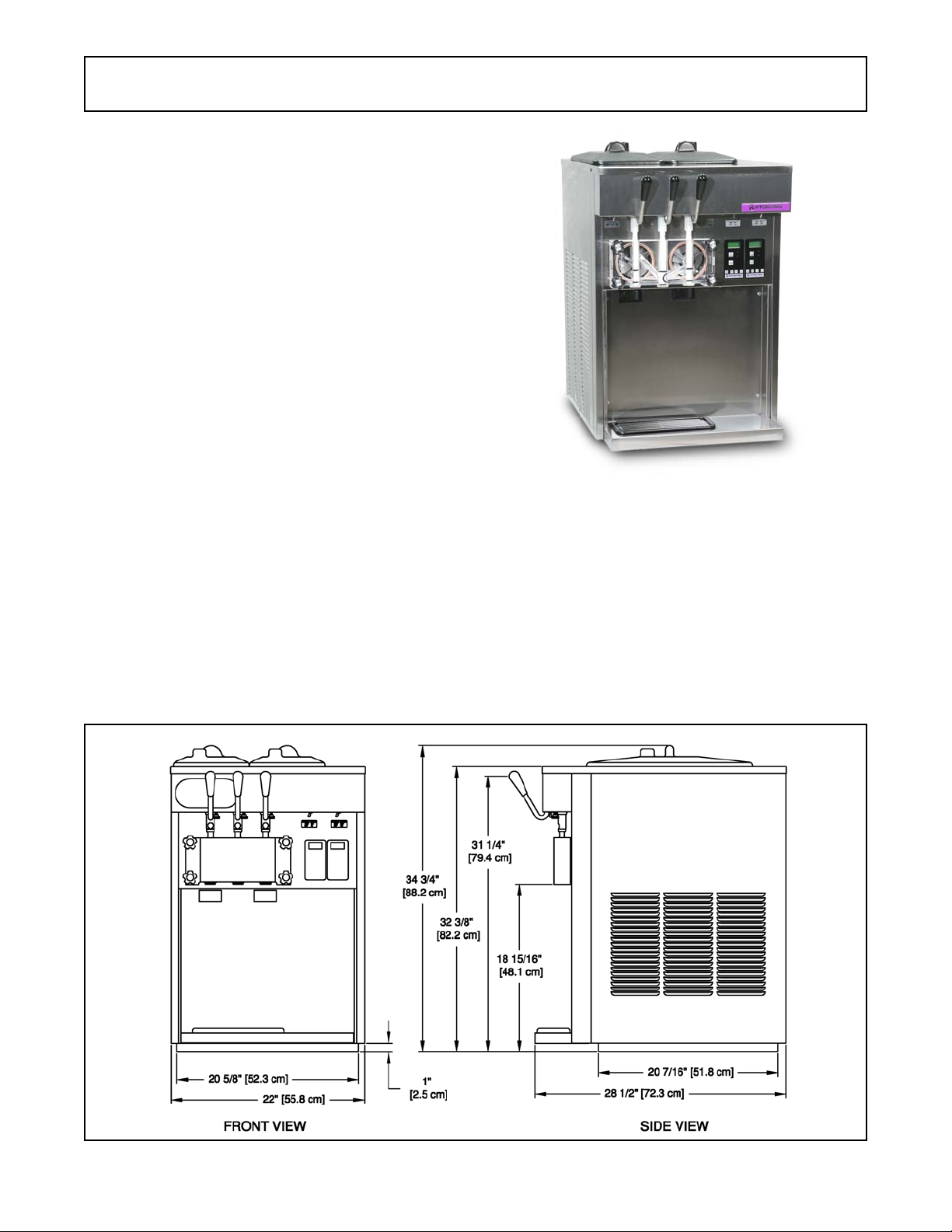
Figure 1-1 E131OT2 / F131OT2 Machine
1.2 SPECIFICATIONS
Figure 1-2 Specification
1
Page 8

1.2 E131I SPECIFICATIONS
Dimensions
width
height
depth
Weight
Electrical
ru nnin g am ps
con n ection type
In t e r nat ional Option
Compressor
Drive M ot or
Air Flow
Plumbing Fit t i ngs
Hopper Volum e
Freezing Cylinder
Volume
Production
Capacity
Model E 131 OT2
Machine
22'' (55,9 cm)
34-3/ 4' ' (88,3 cm)
28-1/ 2' ' (72,4 cm)
1 Phase, 208-230 VA C, 60Hz
approximately 12A
NEM A6-20P power cor d pr ovided
1 Phas e, 220- 240 VAC, 50H z
8,600 Btu/ h r ( R -404A)
Two - 3/ 4 hp
Air cooled un it s r equire 3" (7, 6 cm ) air sp ace on both sides
Water co ol ed un it s r equire 3/8" N.P.T. water and drain fitt ings.
Tw o - 3 gal l o n (11, 35 l it er s )
Two - 0. 5 gal lon (2 qua rt), 1,89 lit er s
5 GPH ( 18, 93 liters) each Fr eezin g Cy linder
8.5 G PH ( 32, 18 liter s) bot h Freezin g Cy linders
with crat e
28'' (71,1 cm)
40-1/ 4' ' (102,2 cm)
35-1/ 4'' (8 9, 5 cm )
450 lbs ( 204,1 kg)370 l bs (167,8 kg)
Refrigerant
Charge
Suction Pr essur e
(at 72° F)
Discharge Pr essur e
Hot Gas Bypass
Pressure
EPR Valve
E131OT2
R-404A
(W/C) 26 oz
(A/C) 32 oz
One Cylinder 22- 24 ps ig
Hopper O nl y 14 psig
225-235 p sig
14 psig (on ly hopper r un nin g)
59-61 psig
Menu Display Value
Basic
Advanced
Storage
(Left
control
only)
Cu tOut * amps
Cut In T 22 °F
Cyc l es 20 cou nt
Stir O n 15 secon d s
Stir Off 300 seconds
On Time 25 secon d s
Off T ime 450 seconds
Stb Time 120 minut es
Sl1DrvO n 120 seconds
Sl1DrO ff 180 seconds
Sl2Cu t In 35 °F
Sl2CtOut 30 °F
DftOffTm 600 seconds
Refriger ** 2 Hopper
Hpr CutIn 37.5 ° F
Hpr Ct O ut 32 °F
HprOffst 8 °F
Hpr Off 13 minutes
Hpr On 130 secon ds
* CutOut amps must be set on site.
** The Refriger setting on the right control board
must be set to None.
2
Page 9

1.2 F131I SPECIFICATIONS
Dimensions
width
height
depth
Weight
Electrical
ru nnin g am ps
con n ection type
In t e r nat ional Option
Compressor
Drive M ot or
Air Flow
Plumbing Fit t i ngs
Hopper Volum e
Freezing Cylinder
Volume
Production
Capacity
Model F131OT2
Machine
22'' (55,9 cm)
34-3/ 4' ' (88,3 cm)
28-1/ 2' ' (72,4 cm)
1 Phase, 208-230 VA C, 60Hz
approximately 12A
NEM A6-20P power cor d pr ovided
1 Phas e, 220- 240 VAC, 50H z
12,000 Btu/ hr ( R-404A)
Two - 3/ 4 hp
Air cooled un it s r equire 3" (7, 6 cm ) air sp ace on both sides
Water co ol ed un it s r equire 3/8" N.P.T. water and drain fitt ings.
Tw o - 3 gal l o n (11, 35 l it er s )
Two - 0. 85 gal lon ( 3. 4 quart ) , 3,22 l it er s
8 GPH (30,29 liter s) each Freez in g Cy l in der
11.5 G PH ( 43,53 lit er s) bot h Free zing Cylin d er s
with crat e
28'' (71,1 cm)
40-1/ 4' ' (102,2 cm)
35-1/ 4'' (8 9, 5 cm )
470 lbs ( 213,1 kg)385 l bs (174,6 kg)
Refrigerant
Charge
Suction Pr essur e
(at 72° F)
Discharge Pr essur e
Hot Gas Bypass
Pressure
EPR Valve
F131OT2
R-404A
(W/C) 32 oz
(A/C) 42 oz
One Cylinder 22- 24 ps ig
Hopper O nl y 14 psig
225-235 p sig
14 psig (on ly hopper r un nin g)
59-61 psig
Menu Display Value
Basic
Advanced
Storage
(Left
control
only)
Cu tOut * amps
Cut In T 22 °F
Cyc l es 20 cou nt
Stir O n 15 secon d s
Stir Off 300 seconds
On Time 15 secon d s
Off T ime 450 seconds
Stb Time 120 minut es
Sl1DrvO n 120 seconds
Sl1DrO ff 180 seconds
Sl2Cu t In 33 °F
Sl2CtOut 30.5 °F
DftOffTm 600 seconds
Refriger ** 2 Hopper
Hpr CutIn 37.5 ° F
Hpr Ct O ut 32 °F
HprOffst 8 °F
Hpr Off 13 minutes
Hpr On 130 secon ds
* CutOut amps must be set on site.
** The Refriger setting on the right control board
must be set to None.
3
Page 10
1.3 MODES OF NORMAL OPERATION
Following are details of the operational modes of the
IntelliTec control.
NOTE:
The preset amounts, times, and temperatures listed
below are references to actual settings on the
IntelliTec control. Refer to Table 1-1 on page 7 for
details on each setting.
A. INITIAL STATUS
When the Main Freezer Power and Freezing Cylinder
switches are placed in the ON position, the machine will
start in the “Sleep 1 Mode". The display will read "Sleep 1
Mode". The control will eventually move into the “Sleep 2”
mode if the PUSH TO FREEZE button is not pressed.
When the PUSH TO FREEZE button is pressed the control
will move to the “Serve Mode”.
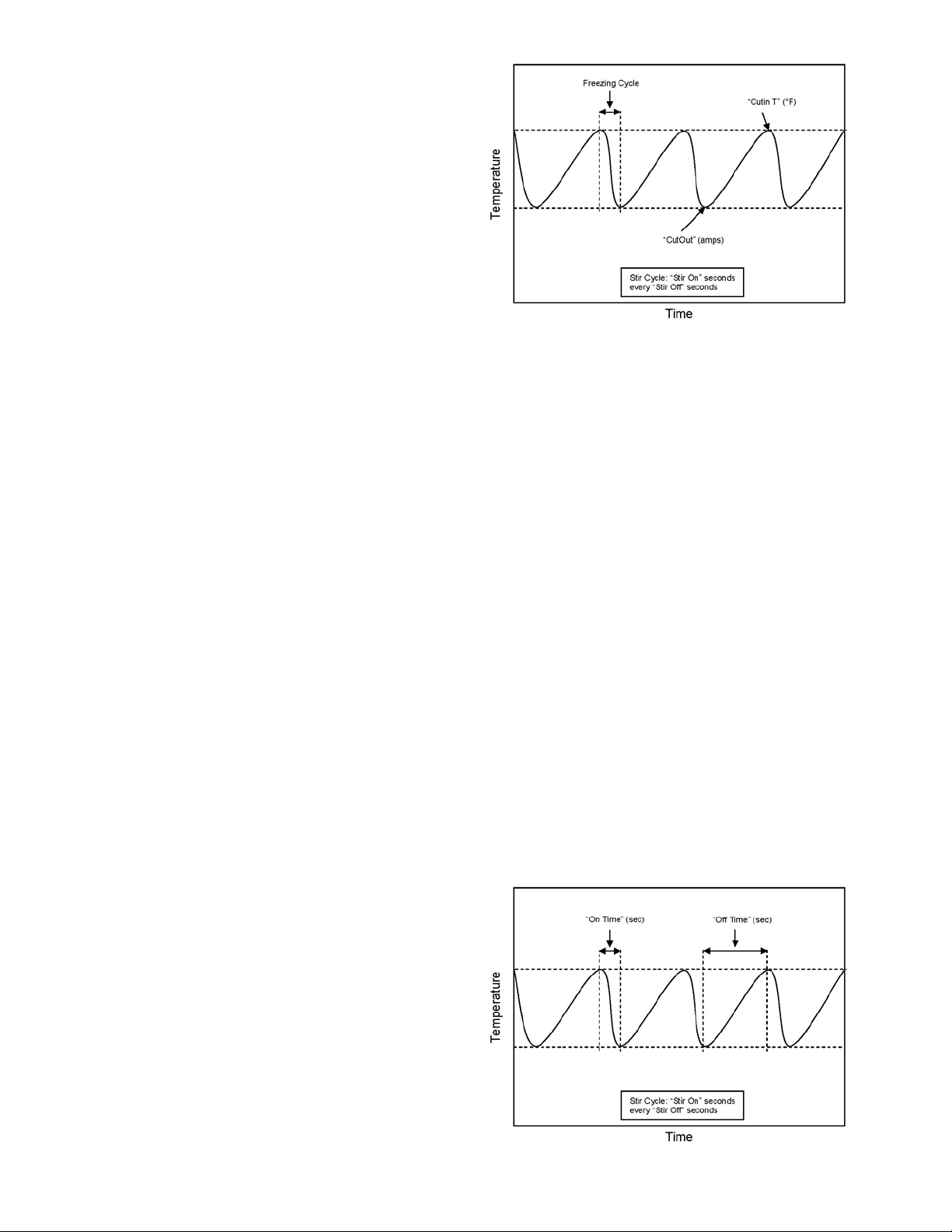
B. SERVE MODE
When the PUSH TO FREEZE button is pressed or a spigot
handle is pulled, the “Serve Mode” begins. The drive motor
starts, and after a 3 second delay, the compressor starts.
The display reads “FREEZING” on the top line and a bar on
the bottom line increases with product consistency. A
toroid on the IntelliTec control senses increasing drive
motor amperage as the product comes to consistency in
the freezing cylinder. When the control senses the product
is at 75% of consistency, the display will read "SERVE",
the amber LED will go out, and the green LED will flash. At
this time, product can be served from the machine. The
drive motor and compressor will continue to run until the
toroid reads a preset value (CutOut amps). When the toroid
reads the CutOut amps on the drive motor, the compressor
turns off and the green LED will remain lit. After a 3 second
delay, the drive motor turns off. The product in the freezing
cylinder is now at serving temperature and consistency.
After product is at consistency, the IntelliTec control
continuously monitors refrigerant temperature through a
thermistor mounted on the side of the freezing cylinder.
When the temperature increases to a preset amount (Cut
In T), a 3-second drive motor pre-stir analyzes product
consistency. The pre-stir check is also performed each
time the spigot handle is opened. This check prevents overfreezing of product, especially during frequent, small volume draws. If the product requires a freezing cycle, the
control will start the cycle.
During the “Serve Mode”, a stir cycle starts. This cycle is
independent of the freezing cycle and is based on preset
times (Stir On and Stir Off). The stir cycle prevents product
separation. If a freezing cycle is initiated, the timer is reset.
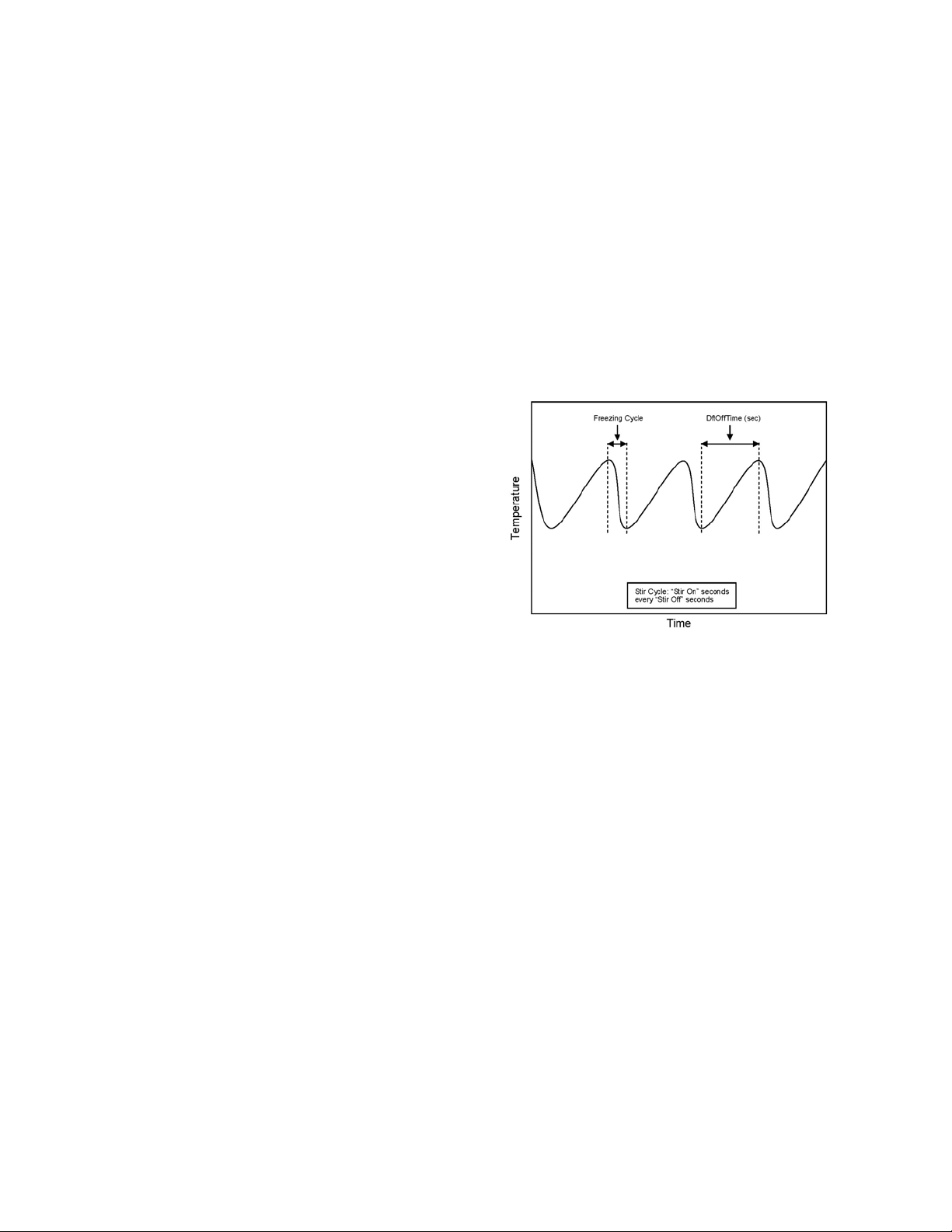
In addition to the "Serve Mode" freezing cycle, there is a
freezing cycle based on a preset time (DftOffTime). If this
time is attained without a freezing cycle, the control will
automatically start a freezing cycle.
The machine will remain in “Serve Mode” until the cycle
count setting is attained. The cycle count is the number of
active freezing cycles and is based on a preset value
Figure 1-3 Serve Mode
(Cycles). Once the cycle count has been reached without
user interruption, the control will move into the "Standby
Mode".
If the PUSH TO FREEZE button is pressed or a spigot
handle is pulled, the cycle count is reset and the control will
move to the beginning of the "Serve Mode". Refer to Figure
1-3 for a graphical representation of the "Serve Mode".
C. STANDBY MODE
If no product has been drawn from the spigot and the preset
number of active freezing cycles is met, the control moves
into the “Standby Mode”. In "Standby Mode", the freezing
cycle is based on preset timers (On Time and Off Time), and
prevents ice crystals from building up in the product.
Because the product remains partially frozen, it can quickly
return to servable consistency when the PUSH TO FREEZE
button is pressed.
During “Standby Mode”, the stir cycle runs. This cycle is
based on preset, timed intervals (Stir On and Stir Off) and
prevents product separation.
The "Standby Mode" maintains product quality during slow
times, while minimizing reactivation time. This mode lasts
for a preset time (Stb Time). Once this time has been
reached without user interruption, the control moves into
Figure 1-4 Standby Mode
4
Page 11
the "Sleep 1 Mode". Refer to Figure 1-4 for a graphical
representation of the "Standby Mode".
If a spigot is opened or the PUSH TO FREEZE button is
pressed, the control will move to “Serve Mode”. Product in
the front of the freezing cylinders may or may not be at
consistency. The state of the product is dependant on a
number of variables but will come to consistency quickly.
D. SLEEP 1 MODE
After the “Standby Mode” time has expired without user
interruption, the control will move into the “Sleep 1 Mode”.
During the "Sleep 1 Mode", the stir cycle is handled by
preset timers (Sl1DrvOn and Sl1DrOff), and allows product
to melt to a liquid state by using agitation cycles without
any flow of refrigerant. Although the product temperature
never increases above 40°F, the product thaws rapidly
which minimizes product breakdown. The control will stay
in the “Sleep 1 Mode” until sensing a preset temperature
(Sl2CutIn). When this temperature has been reached
without user interruption, the control will move to the "Sleep
2 Mode". Refer to Figure 1-5 for a graphical representation
of the "Sleep 1 Mode".
Figure 1-5 Sleep 1 Mode
If a spigot is opened or the PUSH TO FREEZE button is
pressed, the control will move to “Serve Mode”. If the spigot
is opened in "Sleep 1 Mode", the product will not be at
consistency. The operator must wait until the first "Serve
Mode" freezing cycle has completed to serve product.
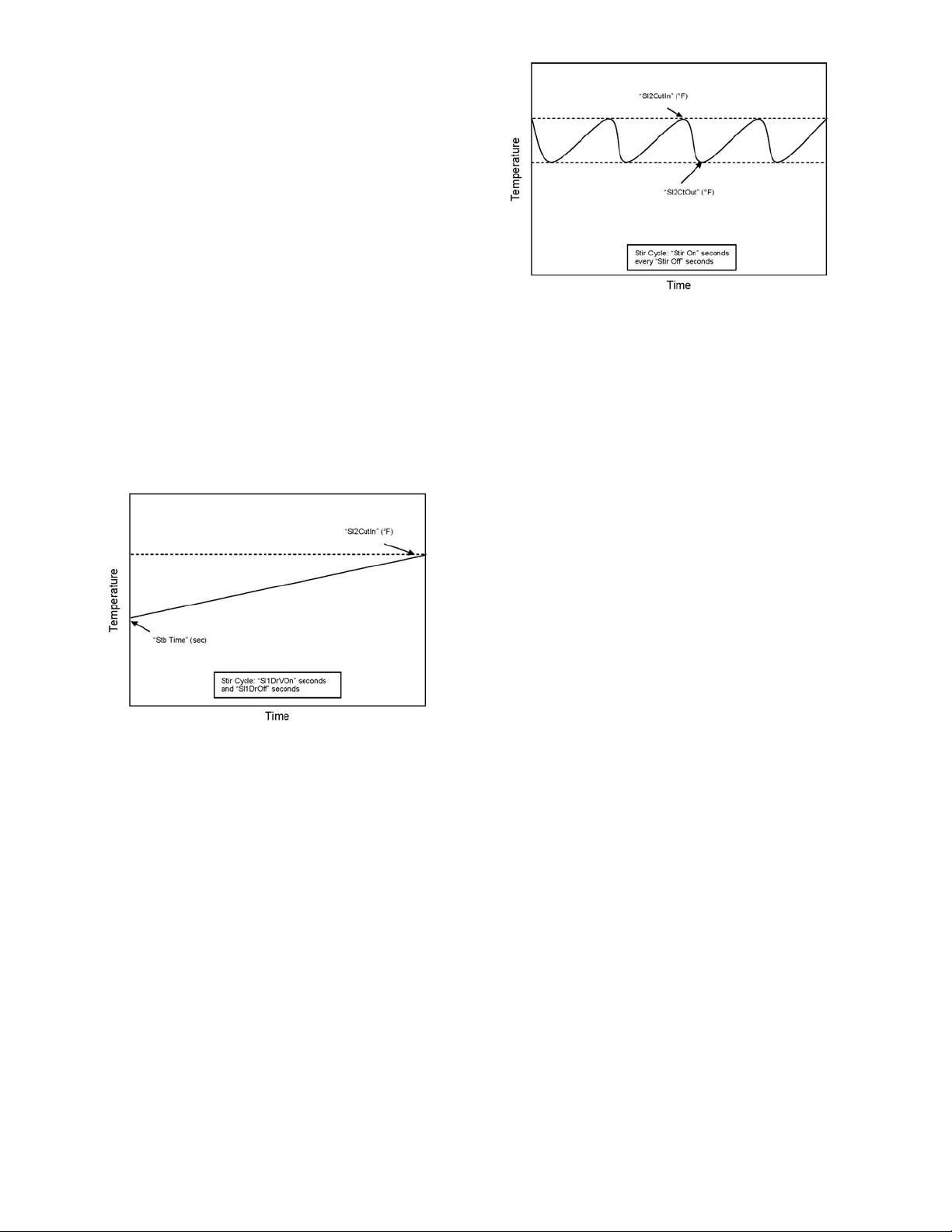
E. SLEEP 2 MODE
The “Sleep 2 Mode” maintains the freezing cylinder temperature between two preset values (Sl2CutIn and Sl2CtOut).
During the “Sleep 2 Mode”, the stir cycle runs. This cycle
is based on preset, timed intervals (Stir On and Stir Off) and
prevents product separation. The "Sleep 2 Mode" is often
referred to by customers as the “night mode” and the
machine will stay in this mode until a spigot is opened or
the PUSH TO FREEZE button is pressed. When this
occurs, the control will move to “Serve Mode”. If the spigot
is opened at this time, the product will be liquid. The
operator must wait until the first "Serve Mode" freezing
cycle has completed to serve product. Refer to Figure 1-6
for a graphical representation of the "Sleep 2 Mode".
Figure 1-6 Sleep 2 Mode
F. INTELLITEC RESTART (VERSION 3.5 OR HIGHER)
If a hard error occurs (refer the hard error list below), the
IntelliTec control will wait 5 minutes then attempt to clear
the error by restarting itself. The control will count each
restart attempt. The restart count will reset if the PUSH TO
FREEZE button is pressed, the spigot is pulled, or the
Freezing Cylinder OFF/ON switch is placed in the OFF
position.
The following are considered hard errors:
ERROR CODE MALFUNCTION
2 High Torque
3 Run Time
4 Clean
7 Drive Motor
9 High Pressure Cutout
When a restart occurs, the second line of the display will
read "Restart" and the backlight will blink. This will occur
regardless of the system mode.
G. SLEEP 3 MODE (VERSION 3.5 OR HIGHER)
If a high torque, run time, or drive motor error condition
occurs on the third restart attempt, the control will move to
the "Sleep 3 Mode".
In "Sleep 3 Mode" freezing cylinder refrigeration will run for
4 seconds every 10 minutes. This ensures the product
temperature never increases above 40°F. The stir cycle
and the auger do not run during "Sleep 3 Mode".
The control will exit "Sleep 3 Mode" if the PUSH TO
FREEZE button is pressed, the spigot is pulled, or the
Freezing Cylinder OFF/ON switch is placed in the OFF
position.
H. CLEAN MODE
When the CLEAN button is pressed on the left side, all
hopper refrigeration stops. When the CLEAN button is
pressed on the right side, only the right barrel freezing cycle
stops. In either case, the drive motor of that barrel starts and
will run for 20 minutes and a 5 minute countdown timer is
displayed. After the time has elapsed, an optional audible
alarm will sound if this accessory has been installed. The
5
Page 12
audible alarm is a reminder for the operator to end the
"Clean Mode" when cleaning is completed.
If the machine is kept in "Clean Mode" for more than 20
minutes, the auger drive motor stops, the hopper refrigeration starts, and an error code (E4) is displayed on the
display panel. The error code prevents damage to the
machine that could occur during an extended clean mode
(Refer to Section 8 - Troubleshooting for details). To clear
this error, place the Freezing Cylinder Off-On switch in the
Off position and back in the On position. If the machine is
still being cleaned, pushing the CLEAN button will reset the
timer and restart the "Clean Mode".
1.4 MIX LEVEL INDICATORS
The hoppers are equipped with a sensor that monitors mix
level. When the mix level drops below the sensor probe, the
lower line of the display will read "Low Mix" and the display
will flash. To clear the "Low Mix" error, add mix to the
hopper.
1.5 HOPPER REFRIGERATION
The IntelliTec control is programmed to handle refrigeration
of the hopper independently from the freezing cylinder. The
left control maintains hopper temperature between two
preset values (HprCutIn and HprCtOut).
NOTE
The Refriger setting should be 2 Hopper for the Left
control and None for the right control.
The hopper refrigeration cycle starts when the temperature
of either hopper reaches the HprCutIn value and stops when
both hoppers reach the HprCutOut value.
In addition to this refrigeration cycle, hopper refrigeration
may start when the freezing cycle starts. This reduces
compressor cycles which preserves compressor life. Hopper refrigeration will start if the hopper temperature is above
a preset value (HprOffst + HprCtOut). This value is always
between HprCutIn and HprCtOut. Refrigeration of the hopper will continue until the HprCtOut is reached or until the
freezing cycle is completed in the freezing cylinder.
The refrigeration cycle will run for a maximum of 4 minutes.
After 4 minutes, the refrigeration cycle will stop for a
minimum of 3 minutes. At the expiration of 3 minutes, the
control will check product temperature. If product temperature is at or above HprCutIn, another refrigeration cycle will
start.
NOTE
If the temperature in the cabinet stays above 50°F
for more than two hours, the machine will go into
Sleep Mode and a clean message will be shown on
the display .
1.6 OPERATION DURING SENSOR FAILURE
The IntelliTec control is designed to allow the machine to
continue to function if a temperature sensor failure occurs.
If a sensor fails, the display will show the error and the
control will run the machine on timers for the freezing cycle
or hopper refrigeration. This allows the operator to continue
to serve product from the machine until proper servicing can
be completed.
A. SERVE AND STANDBY MODE
In the event of a temperature sensor failure on a freezing
cylinder, the IntelliTec control will function in two modes,
"Serve Mode" and "Standby Mode". When the product is at
consistency in "Serve Mode", the IntelliTec control uses a
timer instead of the sensor and will not start another
freezing cycle until a preset value (DftOffTme) is met.
The control will monitor product after it is at consistency,
activating the stir cycle and counting the number of cycles.
When the cycle count is reached, the control will move to
"Standby Mode".
Figure 1-7 Serve Mode (Sensor Failure)
The "Standby Mode" is the same as in normal operation
with the exception of when the preset time (Stb Time) is
met, the control moves back into the "Serve Mode". Refer
to Figure 1-7 for details.
In the event a hopper temperature sensor fails, the control
will use the temperature of the other hopper to control the
refrigeration cycle.
If both temperature sensors fail, the refrigeration cycle is
managed by preset times (Hpr On and Hpr Off). This
refrigeration cycle is independent of the freezing cycle.
1.7 MOTOR PROFILE CUTOUT
COMPENSATION
The IntelliTec control is programmed to automatically
function at a range of supply voltages. This feature provides
the advantage of having product maintained at a specific
temperature and consistency irrespective of the supply
voltage. A motor profile curve is programmed on the
IntelliTec control and provides a relationship between the
supply voltage and drive motor cutout amperage. Depending on the supply voltage, the control varies cutout amperage according to the motor profile. This feature is automatic
and does not need any configuring.
6
Page 13

In tellIT ec Control Se tting Specification s
Basic Menu
Advanced Menu
DISPLAY MODE DEFINITION
CutOut Serve Am p draw setting for cut out
Cut In T Serve Temperature setting for cut i n
Cyc l es S erve Freez i ng c ycl es before going int o Standby M ode
St i r On Serve Stir-only on tim e
St i r Off Serve St i r-onl y off tim e
DISPLAY E131 F131 MODE DEFINITION
On Time 25 sec 15 sec Standby Freezi ng c ycle "on” time (runs on t i m ers onl y)
Off Time 450 s ec 450 sec Standby Freezi ng c ycle “off” tim e
St b Time 120 min 120 min St andby Total t im e i n m ode
Sl1DrvOn 120 sec 120 s ec Sl eep 1 Drive mot or “on” ti m er
Sl1DrOff 180 sec 180 s ec Sleep 1 Drive motor “off” ti mer
Sl2Cut In 35°F 33°F S l eep 2 Cut in temperature
Sl2Ct O ut 30°F 30.5°F Sleep 2 Cut out temperature
DftOffTm 600 sec 600 sec No Sens or Default “off” time. Us ed i n c ase of sensor failure
E131 & F131
*
22°F
20
15 sec
300 sec
Stora ge M e nu
* The CutOut value needs to be adjus ted to product requi rements. Refer to the 2202077 - S pec i fication S heet for E131/ F 131
OT2 Int ell i t ec Control loc ated in the plastic pouch behind the left s i de panel.
** The Refriger s etting on the ri ght control board must be set to None.
DISPLAY MODE DEFINITION
Refriger All Set to None, 1 Hopper, 2 Hopper, or Cabinet
HprCutIn All Refrigerated cab cut in t emperature
HprCtOut All Refrigerated cab cut out temperature
Hpr Off No Sens or Default “off” time. Us ed i n case of sensor failure
Hpr On No S ens or Default “on” ti m e. Us ed i n c ase of sensor failure
E131 & F131
** 2 Hopper
37.5°F
32°F
13 sec
130 sec
T able 1-1 IntelliTec Control Setting Specifications
7
Page 14

8
Page 15
SECTION 2
INSTALLATION INSTRUCTIONS
2.1 SAFETY PRECAUTIONS
Do not attempt to operate the machine until the safety
precautions and operating instructions in this manual are
read completely and are thoroughly understood.
Take notice of all warning labels on the machine. The labels
have been put there to help maintain a safe working
environment. The labels have been designed to withstand
washing and cleaning. All labels must remain legible for
the life of the machine. Labels should be checked periodically to be sure they can be recognized as warning labels.
If danger, warning or caution labels are needed, indicate
the part number, type of label, location of label, and
quantity required along with your address and mail to:
STOELTING
A TTENTION: Customer Service
502 Hwy . 67
Kiel, Wisconsin 53042
2.2 SHIPMENT AND TRANSIT
The machine has been assembled, operated and inspected
at the factory. Upon arrival at the final destination, the
entire machine must be checked for any damage which
may have occurred during transit.
With the method of packaging used, the machine should
arrive in excellent condition. THE CARRIER IS RESPONSIBLE FOR ALL DAMAGE IN TRANSIT, WHETHER
VISIBLE OR CONCEALED. Do not pay the freight bill until
the machine has been checked for damage. Have the
carrier note any visible damage on the freight bill. If
concealed damage and/or shortage is found later, advise
the carrier within 10 days and request inspection. The
customer must place claim for damages and/or shortages
in shipment with the carrier. Stoelting, Inc. cannot make
any claims against the carrier.
2.3 MACHINE INSTALLATION
WARNING
Installation must be completed by a qualified
electrician/refrigeration specialist.
Incorrect installation may cause personal injury , severe damage to the machine and will void factory
warranty.
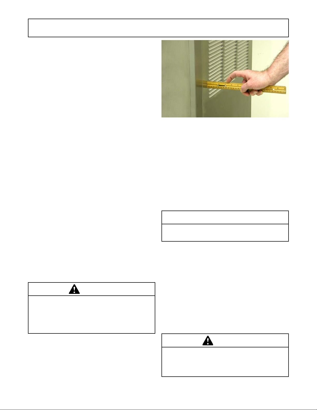
Figure 2-1 Space and Ventilation Requirements
Place a bubble level on top of the machine at each
corner to check for level condition. If adjustment
is necessary, level the machine by turning the
bottom part of each leg in or out.
C. The machine has a base gasket that must be
installed. Separate the gasket and install it with
the seam to the back. Make sure the angled side
of the gasket is facing up.
C. Correct ventilation is required. The right side of the
machine is the air intake and left side is the
discharge. Both sides must have 3" clearance.
CAUTION
Failure to provide adequate ventilation will void warranty .
D. Place the Main Freezer Power Off/On switch in
the OFF position.
E. Connect the power cord to the proper power
supply. The plug connected to the machine is a
NEMA 6-20P. Check the nameplate on your
machine for proper supply. The unit must be
connected to a properly grounded receptacle.
The electrical cord furnished as part of the machine
has a three prong grounding type plug. The use of
an extension cord is not recommended, if
necessary use one with a size 12 gauge or heavier
with ground wire. Do not use an adapter to
circumvent the grounding requirement.
Installation of the machine involves moving the machine
close to its permanent location, removing all crating,
setting in place, assembling parts, and cleaning.
A. Uncrate the machine.
B. Accurate leveling is necessary for correct drainage
of machine barrel and to insure correct overrun.
WARNING
Do not alter or deform electrical plug in any way.
Altering the plug to fit into an outlet of different configuration may cause fire, risk of electrical shock,
product damage and will void warranty .
9
Page 16

10
Page 17

SECTION 3
INITIAL SET-UP AND OPERATION
3.1 OPERATOR’S SAFETY PRECAUTIONS
SAFE OPERATION IS NO ACCIDENT; observe these
rules:
A. Know the machine. Read and understand the
Operating Instructions.
B. Notice all warning labels on the machine.
C. Wear proper clothing. Avoid loose fitting garments,
and remove watches, rings or jewelry that could
cause a serious accident.
D. Maintain a clean work area. Avoid accidents by
cleaning up the area and keeping it clean.
E. Stay alert at all times. Know which switch, push
button or control you are about to use and what
effect it is going to have.
F. Disconnect power for maintenance. Never attempt
to repair or perform maintenance on the machine
until the main electrical power has been
disconnected.
G. Do not operate under unsafe operating conditions.
Never operate the machine if unusual or excessive
noise or vibration occurs.
3.2 OPERATING CONTROLS AND
INDICATORS
Before operating the machine, it is required that the
operator know the function of each operating control. Refer
to Figure 3-1 for the location of the operating controls on the
machine. For the information regarding error codes displayed on the control panel, refer to the troubleshooting
section of this manual.
WARNING
High voltage will shock, burn or cause death. The
OFF-ON switch must be placed in the OFF position
prior to disassembling for cleaning or servicing. Do
not operate machine with panels removed.
Main Freezer
Power Off/On
Freezing Cylinder
Off/On Switch
Dispense Rate
Adjustor
IntelliT ec Control
(See Figure 3-2)
Figure 3-1 Machine Controls
11
Page 18
A. MAIN FREEZER POWER SWITCH
The Main Freezer Power switch is a two position rocker
switch that supplies power to the IntelliTec control, freezing cylinder circuits and hopper refrigeration system. When
the switch is placed in the ON position, the hopper refrigeration system will run until the preset temperature is
reached; then it will cycle ON and OFF to maintain that
temperature.
B. FREEZING CYLINDER OFF/ON SWITCH
The Freezing Cylinder OFF/ON switch is a two position
toggle switch used to supply power to the freezing cylinder
control circuit. When the switch is in the OFF position, the
freezing cylinder’s refrigeration system and auger will not
operate. When the switch is in the ON position, the
machine will be operational.
C. SPIGOT SWITCH
The spigot switch is mounted to the spigot cam assembly
behind the header panel. When the spigot is opened to
dispense product, the spigot switch opens and the "Serve
Mode" begins.
D. DISPENSE RATE ADJUSTOR
The dispense rate adjustor is located under the header
panel, to the immediate right of the spigot handles. Turning the knob counterclockwise will decrease the dispense
rate.
E. PUSH TO FREEZE BUTTON
The PUSH TO FREEZE button is a membrane or snap
switch used to initiate "Serve Mode".
NOTE
After the PUSH TO FREEZE button is pressed, the
drive motor starts. Af ter a 3-second delay , the compressor will start.
F. LEDS
The membrane switch (touchpad) features two lights: a
green LED and an amber LED. The green LED is lit during
"Serve Mode". During freeze down, it is not lit. When
product consistency approaches 75% in the freezing
cylinder, the green LED flashes. The amber LED is on
during all other modes. Both LEDs alternatively flash if an
error occurs or if the freezing cylinder is off.
G. CLEAN BUTTON
The CLEAN button is a membrane, or snap switch. When
the button is pressed, the freezing cycle stops and the
drive motor will start. A CLEAN message will display on the
LCD screen along with a 5-minute countdown timer. To
exit the CLEAN mode, turn the Freezing Cylinder OFF/ON
switch to the OFF position or press the CLEAN button
again. If the machine is left in CLEAN for more than 20
minutes, an error code (E4) will be displayed on the display
panel. Place the Freezing Cylinder OFF/ON switch in the
OFF position and back in the ON position to clear this
error.
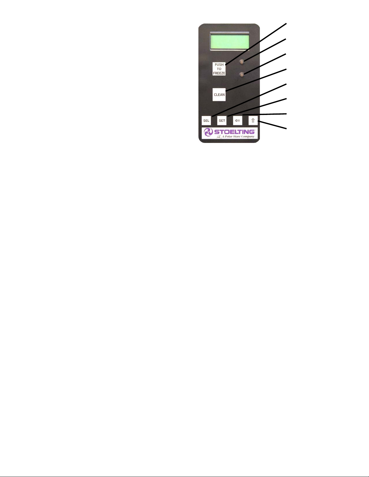
Push to Freeze
Green LED
Amber LED
Clean Button
SEL Button
SET Button
Left Arrow Button
Up Arrow Button
Figure 3-2 IntelliT ec Control
H. DRIVE MOTOR OVERLOAD
The internal drive motor overload will trip if the drive motor is
overloaded. It will reset after approximately 10-12 minutes.
If the drive motor continues to trip, refer to Troubleshooting
in Section 7.
I. MIX LOW LIGHT INDICATOR
A MIX LOW message will appear on the LCD display to
alert the operator of a low mix condition. The message will
display when there is approximately one gallon of mix left
in the hopper. When the MIX LOW message is displayed,
refill the hopper immediately.
L. MENU NAVIGATION BUTTONS
The Menu Navigation Buttons allow the user to display
information regarding the machine’s status of operation as
well as adjust product consistency (Fig. 3-2).
Selection Button (SEL) The SEL button is used
in combination with the up arrow button to enter
into the settings of the IntelliTec control. This
button is also used to navigate through the control
settings menu.
Set Button (SET) The SET button is used to save
a change made to the product consistency setting.
It is also used to save changes when modifying
control settings.
Left Arrow Button (⇐) If the left arrow button is
pressed for 5 seconds, the display will remain lit.
To turn the light off, press the left arrow button for
5 seconds. The left arrow button is used primarily
to navigate through the control settings.
Up Arrow Button (⇑) After pressing the SET
button, the up arrow button will change the value
of the product consistency setting. This button is
also used to navigate through the control settings.
12
Page 19

3.3 IMPORTANT INFORMATION REGARDING CLEANING
AND SANITIZING
Soft serve machines require special consideration when it
comes to food safety and proper cleaning and sanitizing.
The following information specifically covers issues for
cleaning and sanitizing frozen dessert machines. This
information is meant to supplement a comprehensive food
safety program.
SOIL MATERIALS ASSOCIATED WITH FROZEN
DESSERT MACHINES
MILKFAT/BUTTERFAT – As components of ice-cream/
frozen custard mix, these soils will accumulate on the
interior surfaces of the machine and its parts. Fats are
difficult to remove and help attribute to milkstone buildup.
MILKSTONE – Is a white/gray film that forms on equipment and utensils that are exposed to dairy products.
These films will accumulate slowly on surfaces because of
ineffective cleaning, use of hard water, or both. Milkstone
is usually a porous deposit, which will harbor microbial
contaminants and eventually defy sanitizing efforts.
Once milkstone has formed, it is very difficult to remove.
Without using the correct product and procedure, it is
nearly impossible to remove a thick layer of milkstone.
(NOTE: general-purpose cleaners DO NOT remove
milkstone.) This can lead to high bacteria counts and a
food safety dilemma.
IT IS BEST TO CONTROL MILKSTONE ON A DAILY
BASIS BEFORE IT CAN BECOME A SIGNIFICANT FOOD
SAFETY PROBLEM.
In addition to food safety, milkstone can cause premature
wear to machine parts, which can add to costs for replacement parts or possibly more expensive repairs if worn
machine parts are not replaced once they have become
excessively worn.
IMPORTANT DIFFERENCES BETWEEN CLEANING
AND SANITIZING
CLEANING vs. SANITIZING
It is important to distinguish between cleaning and sanitiz-
ing. Although these terms may sound synonymous, they
are not. BOTH are required for adequate food safety and
proper machine maintenance.
CLEANING
· Is the removal of soil materials from a surface.
· Is a prerequisite for effective sanitizing.
NOTE
An UNCLEAN surface will harbor bacteria that can
defy sanitizing efforts.
Bacteria can develop and resist sanitizing efforts within a
layer of soil material (milkstone). Thorough cleaning procedures that involve milkstone removal are critical for
operators of frozen dessert machines.
SANITIZING
· Kills bacteria.
· Can be effective on clean surfaces only.
NOTE
Using a SANITIZER on an unclean surface will not
guarantee a clean and safe frozen dessert machine.
PROPER DAILY MAINTENANCE:
The Only Way to Assure Food Safety and Product Quality
Proper daily maintenance can involve a wide variety of
products and procedures. Overall, the products and procedures fall into three separate categories. (Please note
that this is a brief overview intended for informational
purposes only.)
1. CLEANING – This involves draining mix from the
freezing cylinder and rinsing the machine with
water. Next, a cleaner is run through the machine.
Then, the machine is disassembled and removable
parts are taken to the sink for cleaning.
2. MILKSTONE REMOVAL – Since most cleaners
do not have the ability to remove milkstone, the
use of a delimer becomes necessary. Although
this procedure may not be needed on a daily
basis, it will usually follow the cleaning procedure.
It requires letting a delimer solution soak in the
machine for an extended period. Individual parts
are also soaked in a deliming solution for an
extended period of time (more about delimers in
Additional Information).
3. SANITIZING – After the machine has been cleaned
and contains no milkstone, the machine is
reassembled. Then a FDA-approved sanitizing
solution is run through the machine to kill bacteria.
The machine is then ready for food preparation.
As a recommended cleaner and sanitizer for your frozen
dessert machine, STERA-SHEEN has proven to be one of
the best daily maintenance products for:
· CLEANING – Thorough removal of all solids
including butterfat and milk fat.
· MILKSTONE REMOVAL – Complete removal of
milkstone.
· SANITIZING – FDA-approved no rinse sanitizer
for food contact surfaces.
ADDITIONAL INFORMATION
THE USE OF DELIMERS
A delimer is a strong acid that has the ability to dissolve
milkstone. This type of chemical may become necessary
once high levels of milkstone have developed. While
these products are very effective for removing HIGH
levels of milkstone, they are not ideal for two reasons:
1. PRODUCT SAFETY – Strong acids are dangerous
chemicals. Carefully follow safety instructions
provided with delimer products.
13
Page 20

2. MACHINE DAMAGE – Strong acids will attack
metal and rubber causing premature wear of
parts. The use of a delimer needs to be closely
monitored to avoid damage to machine surfaces
and parts.
With proper daily use of STERA-SHEEN or its equivalent,
there is no need for the use of a DELIMER.
DO NOT USE BLEACH
· BLEACH HAS ABSOLUTELY NO CLEANING
PROPERTIES.
· BLEACH IS CORROSIVE. It will damage
components of the machine causing premature
wear and metal corrosion.
GENERAL PURPOSE CLEANERS
General purpose cleaners do not have the ability to re-
move milkstone. Milkstone will become a problem if not
remedied with additional products and procedures.
THE USE OF CHLORINE TEST STRIPS
“Test strips” are used to determine concentrations of
active chlorine in sanitizing solutions. To use the strips,
tear off a small portion and submerge it into the sanitizing
solution. Then, compare the color change to the color key
on the side of the test strip dispenser to determine the
approximate chlorine concentration.
The ideal concentration of chlorine needs to be 100 ppm
(as stated by the FDA).
NOTE
Follow the directions on the container for proper concentration.
Two main factors contribute to falling chlorine concentrations in a sanitizing solution.
1. PRODUCT USE – As the chlorine in the solution
is being used, chlorine concentrations fall.
2. TIME – As time passes, small amounts of chlorine
“evaporate” from the solution. (That is why you
can smell it.)
Sanitizing solutions should not be allowed to fall below 100
ppm chlorine. New solutions should be mixed once old
solutions become ineffective.
Inspection for worn or broken parts should be made at every
disassembly of the machine. All worn or broken parts
should be replaced to ensure safety to both the operator and
the customer and to maintain good machine performance
and a quality product. Check the wear line on the auger
flights on a regular basis (Fig. 3-3) and replace as needed.
Frequency of cleaning must comply with the local health
regulations.
Wear Line
Figure 3-3 Auger Flight Wear
To disassemble the machine, refer to the following steps:
A. DISASSEMBLY OF FRONT DOOR
1. Turn the Main Freezer Power Off/On switch to the
OFF position.
2. Remove the knobs on the front door.
3. Remove the front door by pulling it off the studs.
4. Remove the spigot through the bottom of the front
door.
5. Remove all o-rings from parts by first wiping off
the lubrication using a clean towel. Then squeeze
the o-ring upward to form a loop (Fig. 3-4). Roll the
o-ring out of the groove.
CAUTION
Do not use any type of sharp object to remove the
o-rings.
3.4 DISASSEMBLY OF MACHINE PARTS
WARNING
High voltage will shock, burn or cause death. The
OFF-ON switch must be placed in the OFF position
prior to disassembling for cleaning or servicing. Do
not operate machine with panels removed.
Before using the machine for the first time, complete
machine disassembly, cleaning and sanitizing procedures
need to be followed. Routine cleaning intervals and procedures must comply with the local and state health codes.
Figure 3-4 Removing O-Ring
14
Page 21

B. DISASSEMBLY OF AUGER
1. Remove the front auger support and bushing.
2. Remove the auger assembly from the machine.
Pull the auger out of the machine barrel slowly. As
the auger is being pulled out, carefully remove
each of the plastic flights with springs.
3. Keep the rear of the auger tipped up once it is clear
of the freezing cylinder to prevent the rear seal
assembly from dropping.
4. Wipe the spline lubricant off of the hex end of the
auger with a paper towel. Remove the rear seal
assembly (Fig. 3-5).
5. Unscrew the springs from the auger flights.
Figure 3-6 Clean Hoppers
D. Clean the rear seal surfaces from the inside of the
freezing cylinder with the 90° to 110°F (32° to
43°C) detergent water.
3.6 SANITIZING MACHINE PARTS
A. Use Stera-Sheen or equivalent sanitizing solution
mixed according to manufacturer’s instructions to
provide a 100 parts per million strength solution.
Mix sanitizer in quantities of no less than 2 gallons
of 90° to 110°F (32°C to 43°C) water. Any sanitizer
must be used only in accordance with the
manufacturer’s instructions.
B. Place all parts in the sanitizing solution for 5
minutes, then remove and let air dry completely
before assembling in machine.
Figure 3-5 Rear Seal Assembly
3.5 CLEANING DISASSEMBLED PARTS
Disassembled machine parts require complete cleaning,
sanitizing and air drying before assembling. Local and
state health codes will dictate the procedure required.
Some state health codes require a four sink process (prewash, wash, rinse, sanitize, air dry), while others require a
three sink process (without the pre-wash step). The following procedures are a general guideline only. Consult
your local and state health codes for the procedures
required in your location.
A. Prepare detergent water by mixing 2 oz. of
Palmolive detergent or equivalent in 2 gallons of
90° to 110°F (32° to 43°C) water. Place all parts
in the detergent solution and clean with provided
brushes.
B. Rinse all parts with clean 90° to 110°F (32° to
43°C) water.
C. Wash the hopper and freezing cylinder with the
90° to 110°F (32° to 43°C) detergent water and
brushes provided (Refer to Figure 3-6).
3.7 CLEANING THE MACHINE
The exterior should be kept clean at all times to preserve the
luster of the stainless steel. A high grade of stainless steel
has been used on the machine to ease cleanup. To remove
spilled or dried mix, wash the exterior with 90° to 110°F
(32°C to 43°C) detergent water and wipe dry.
Do not use highly abrasive materials, as they will mar the
finish. A mild alkaline cleaner is recommended. Use a soft
cloth or sponge to apply the cleaner. For best results, wipe
with the grain of the steel.
A. Clean the rear seal surface from inside of the
freezing cylinder.
B. Using sanitizing solution and the large barrel
brush provided, sanitize the freezing cylinder by
dipping the brush in the sanitizing solution and
brushing the inside of the freezing cylinder.
C. Remove the drip tray by pulling from the front
panel. Clean and replace the drip tray.
15
Page 22

3.8 ASSEMBLING MACHINE
To assemble the machine parts, refer to the following steps:
NOTICE
Petrol-Gel sanitary lubricant or equivalent must be
used when lubrication of machine parts is specified.
NOTICE
The United States Department of Agriculture and
the Food and Drug Administration require that lubricants used on food processing equipment be
certified for this use. Use lubricants only in accordance with the manufacturer’s instructions.
A. Assemble all o-rings onto parts dry, without
lubrication. Then apply a thin film of sanitary
lubricant to exposed surfaces of the o-rings.
B. Lubricate the rear seal area on the auger shaft
with a thin layer of sanitary lubricant. Install the
rear seal o-ring. Lubricate the outside of the rear
seal o-ring with sanitary lubricant.
C. Install the stainless steel rear seal adapter into the
rear seal dry (without lubricant). Lubricate the
inside metal surface of the rear seal adapter and
install it onto the auger shaft. DO NOT lubricate the
outside of the rear auger seal (Fig. 3-6).
H. Apply a thin layer of sanitary lubricant to the inside
and outside of the auger support bushing. Install
the bushing onto the auger support and install the
auger support into the front of the auger. Rotate
the auger support so that one leg of the support
points straight up.
I. Apply a thin layer of sanitary lubricant to the o-
rings on the spigot body and install the spigot body
through the bottom of the front door.
K. Apply a thin film of sanitary lubricant to the door
seal o-ring and fit it into the groove on the rear of
the front door.
M. Place the front door assembly on the mounting
studs and the push front door against the machine
carefully.
N. Secure the front door to the machine by placing the
knobs on the studs and tightening until finger tight.
Do not overtighten. A proper o-ring seal can be
observed through the transparent front door.
3.9 SANITIZING
Sanitizing must be done after the machine is clean and just
before the machine is filled with mix. Sanitizing the night
before is not effective. However, you should always clean
the machine and parts after using it.
NOTE
The United States Department of Agriculture and
the Food and Drug Administration require that all
cleaning and sanitizing solutions used with food processing equipment be certified for this use.
Figure 3-6 Lubricate Rear Seal
D. Lubricate the hex drive end of the auger with a small
amount of spline lubricant. A small container of
spline lubricant is shipped with the machine.
E. Screw the springs onto the studs in the plastic
flights. The springs must be screwed into the
flights completely to provide proper compression.
F. Install the two plastic flights onto the rear of the
auger and insert it part way into the freezing
cylinder.
G. Install the remaining plastic flights, push the auger
into the freezing cylinder and rotate slowly until the
auger engages the drive shaft.
When sanitizing the machine, refer to local sanitary regulations for applicable codes and recommended sanitizing
products and procedures. The frequency of sanitizing
must comply with local health regulations. Mix sanitizer
according to manufacturer’s instructions to provide a 100
parts per million strength solution. Mix sanitizer in quantities of no less than 2 gallons of 90°F to 110°F (32°C to
43°C) water. Allow sanitizer to contact the surfaces to be
sanitized for 5 minutes. Any sanitizer must be used only in
accordance with the manufacturer’s instructions.
CAUTION
Risk of Product Damage
Avoid prolonged contact of sanitizer with machine
parts. Sanitizer may cause corrosion of stainless
steel parts if there is prolonged contact.
A. Prepare 2 gallons of sanitizing solution following
the manufacturer’s instructions.
B. Install the mix inlet regulator into the hopper.
C. Pour the sanitizing solution into the hopper.
16
Page 23

D. Place the Main Power OFF/ON and Freezing
Cylinder OFF/ON switches in the ON position.
Press the CLEAN button.
E. Check for leaks.
1. Check for leaks at the front door seals.
2. Check the drain tray located under the front dor
for leaks coming from the rear of the rear auger
seal.
F. Using a sanitized soft bristle brush (or equivalent)
dipped in sanitizing solution, clean the hopper
sides, mix inlet regulator and underside of the
hopper cover.
G. After five minutes, open the spigot to expel
sanitizing solution. Drain all of the solution from
the machine.
H. When the solution has drained, press the CLEAN
button to stop the auger and place the Main Power
OFF/ON and Freezing Cylinder OFF/ON switches
in the OFF position. Allow the freezing cylinder to
drain completely.
The machine is now sanitized and ready for adding mix.
3.10 INITIAL FREEZE DOWN AND OPERATION
Every Stoelting soft serve machine needs to be set on site.
The following adjustment will provide optimal product con-
sistency while prolonging product life.
NOTE
The machine is designed for correct operation in
ambient temperatures between 50°F and 110°F.
Temperatures out of that range may cause refrigeration problems and product quality issues.
A. ADDING MIX
1. Sanitize the machine immediately before use.
2. Make sure the Freezing Cylinder OFF/ON switch
is in the OFF position.
3. Fill the hopper with at least 2.5 gallons of mix.
4. Place a container under the spigot and open the
spigot to allow the mix to flush out about 8 ounces
(0.23 liters) of sanitizing solution and liquid mix.
Close the spigot.
B. PREPARING THE INTELLITEC CONTROL
5. On the IntelliTec control, press and hold the SEL
button for 8 seconds. While still holding the SEL
button, press the up arrow (⇑) button. The LCD
will read “DISPLAY”.
6. Press the left arrow (⇐) button once. The display
will read “BASIC”.
7. Press the up arrow (⇑) button once. The display
will read “CutOut amps”.
8. Press the SET button. A cursor will start blinking
under the far right digit.
9. Change the value to 8.0. Press the left arrow (⇐)
button to move the cursor. Press the up arrow (⇑)
button to increase the digit. When a digit reaches
9, pressing the up arrow (⇑) button again will
change the value to 0.
10. After entering 8.0, press SET to save this value.
The LCD will read “CutOut Set -- OK”.
11. Press the SEL button. The LCD will read “CutOut
amps 8.0”.
12. Press the SEL button twice. The LCD will read
“DISPLAY”.
13. Press the up arrow (⇑) button to navigate to the
“°F” and “amps” readings.
C. INITIAL FREEZE DOWN
14. Press the PUSH TO FREEZE button.
NOTE
After the drive motor starts, there is a 3-second delay
before the compressor starts.
15. As the product freezes, the “amps” value on the
display will increase. When it reaches 2.8A, open
the spigot, take a 6-8 ounce sample and measure
the temperature. For most soft serve mixes, the
desired temperature is between 19.0°F and 19.5°F.
16. Draw samples at every increase of 0.2A until
reaching the desired consistency and temperature.
NOTE
Show the sample to the customer and make sure it
meets their required consistency and temperature.
17. Record the “amps” value.
18. Place the Freezing Cylinder OFF/ON switch in the
OFF position.
D. ADJUSTING THE INTELLITEC CONTROL
19. Press the SEL button. The display will read
“DISPLAY”.
20. Press the left arrow (⇐) button once. The display
will read “BASIC”.
21. Press the up arrow (⇑) button once. The display
will read “CutOut amps”.
22. Change the value to the recorded value by pressing
the SET button. A cursor will start blinking under
the far right digit.
23. Press the left arrow (⇐) button to move the
cursor. Press the up arrow (⇑) button to increase
the digit. When a digit reaches 9, pressing the up
arrow (⇑) button again will change the value to 0.
24. Press the SET button to save the value. The LCD
will read “CutOut Set -- OK”.
25. Press the SEL button. The LCD will read “CutOut
amps” along with the programmed value from the
previous step.
17
Page 24

26. Press the SEL button three times. The LCD will
read “EXITMENU”.
27. Press the up arrow (⇑) button to exit the menu.
28. Adjustment to the control is completed.
E. SERVING PRODUCT
29. Place the Freezing Cylinder OFF/ON switch in the
ON position.
30. Press the PUSH TO FREEZE button.
31. When the product is at 75% consistency, the
display will read “SERVE”.
32. For normal dispensing, move the spigot handle
fully open.
33. The machine dispenses product at a reasonable
draw rate. If the machine is overdrawn, the result is
a soft product or a product that will not dispense
at all. If this occurs, allow the machine to run for
approximately 30 seconds before dispensing more
product. A dispense rate adjustor is located under
the header panel, to the immediate right of the
spigot handle. Turning the knob counterclockwise
will decrease the dispense rate.
34. Do not operate the machine when the MIX LOW
message is displayed. Refill hopper immediately.
NOTE
The machine has a standby and sleep mode. After
a preset number of freezing cycles, it will enter the
standby mode (followed by sleep mode) and remain
there until someone draws product or presses the
PUSH TO FREEZE button. In the sleep mode, the
machine will keep the product below 41°F (5°C).
Sleep modes do not take the place of cleaning and
sanitizing. Federal, State, and local regulatory agencies determine frequency of cleaning and sanitizing.
3.11 NORMAL FREEZE DOWN AND
OPERATION
The following section contains the recommended operating procedures for the safe operation of the machine.
A. Sanitize immediately before use.
B. Make sure the Freezing Cylinder Off/On switch is
in the OFF position.
C. Fill the hopper with at least 2.5 gallons of mix.
D. Place a container under the spigot and open the
spigot to allow the mix to flush out about 8 ounces
(0.23 liters) of sanitizing solution and liquid mix.
E. Place the Freezing Cylinder OFF/ON switch in the
ON position.
F. Press the PUSH TO FREEZE button.
NOTE
After the drive motor starts, there is a 3-second delay before the compressor starts.
G. When the product is at 75% consistency, the
display will read “SERVE”. Open the spigot to
dispense product.
H. The machine dispenses product at a reasonable
draw rate. If the machine is overdrawn, the result is
a soft product or a product that will not dispense
at all. If this occurs, allow the machine to run for
approximately 30 seconds before dispensing more
product. A dispense rate adjustor is located under
the header panel, to the immediate right of the
spigot handle. Turning the knob counterclockwise
will decrease the dispense rate.
I. Do not operate the machine when the MIX LOW
message is displayed. Refill the mix container
immediately.
NOTE
The machine has a standby and sleep mode. After
a preset number of freezing cycles, it will enter the
standby mode (followed by sleep mode) and remain
there until someone draws product or presses the
PUSH TO FREEZE button. In the sleep mode, the
machine will keep the product below 41°F (5°C).
Sleep modes do not take the place of cleaning and
sanitizing. Federal, State, and local regulatory agencies determine frequency of cleaning and sanitizing.
3.12 MIX INFORMATION
Mix can vary considerably from one manufacturer to
another. Differences in the amount of butterfat content
and quantity and quality of other ingredients have a direct
bearing on the finished frozen product. A change in machine
performance that cannot be explained by a technical
problem may be related to the mix.
Proper product serving temperature varies from one
manufacturer’s mix to another. Mixes should provide a
satisfactory product in the 20°F to 24°F range. Diet and
low-carb mixes typically freeze to proper consistency at
higher temperatures.
When checking the temperature, stir the thermometer in
the frozen product to get an accurate reading.
Old mix, or mix that has been stored at too high a
temperature, can result in a finished product that is unsatisfactory. To retard bacteria growth in dairy based mixes,
the best storage temperature range is between 33° to 38°F
(0.5° to 3.3° C).
18
Page 25

SECTION 4
MAINTENANCE AND ADJUSTMENTS
4.1 MACHINE ADJUSTMENT
This section is intended to provide maintenance personnel with a general understanding of the machine adjustments. It is recommended that any adjustments in this
section be made by a qualified person.
4.2 PRODUCT CONSISTENCY
ADJUSTMENT
The operator can adjust product consistency by modifying
the Fine Adjustment setting on the membrane switch. This
is the only adjustment that can be made by the operator
without using a pass code key sequence. Product consistency fine adjustment allows a 0.4 amp maximum adjustment to the drive motor amp draw cutout. Increasing this
setting will increase the drive motor amperage cutout and
increase product consistency. Follow the instructions below to make fine adjustments to product consistency.
A. Place the Main Freezer Power switch in the ON
position.
B. Press the SET button on the Control Panel once.
Fine Adj will appear on the LCD screen.
C. Press the up arrow button (⇑) until the desired
consistency setting is displayed. The higher the
number, the firmer the product consistency. The
control may be set from 1 to 9. The value increases
by 1 each time the up arrow button is pressed.
After the value reaches 9, numbering restarts at 0.
The 0 setting cannot be set.
D. Press the SET button once to save the setting and
return to the current mode display.
4.3 LOCKING THE CONTROL PANEL
The IntelliTec control has a tamper proof mode to prevent
unauthorized use. When set, all buttons on the control
panel are disabled. Follow the instructions below to lock
the control panel
A. Press and hold the PUSH TO FREEZE button for
at least 5 seconds.
B. While still holding the PUSH TO FREEZE button,
press the CLEAN button once.
C. Release both buttons. An asterisk (*) will appear
on the bottom line of the display, indicating that
the control is in the lock out mode.
NOTE:
Repeat steps A, B, and C to unlock the control p anel.
4.4 OBTAINING READINGS AND
MODIFYING SETTINGS (SERVICE
PERSONNEL ONLY)
Readings and settings on the IntelliTec control are accessed through the IntelliTec Control Menu Settings (Refer to Figure 4-2). Locating machine readings and system
function settings are completed using the up arrow (⇑) and
left arrow (
IntelliTec Menu Settings sheet is located in the information
pouch behind the header panel.
IntelliTec Control Readings
To obtain machine readings, locate the value on the
machine's menu settings sheet and follow the steps below.
A. Press and hold SEL button for 8 seconds. While
B. Release both buttons.
C. Press the up arrow button (⇑) to navigate to the
D. Press the up arrow (⇑) and left arrow (
E. When all readings have been obtained, press the
⇐⇐
⇐) buttons on the membrane switch. A printed
⇐⇐
still holding the SEL button, press the up arrow
button (⇑). The LCD Screen will read DISPLAY.
correct reading under DISPLAY or press the left
arrow (
menu.
to navigate through the rest of the readings as
needed.
up arrow button (⇑) from ExitMenu to return to the
current mode display.
⇐⇐
⇐) button to navigate to the ERRCODES
⇐⇐
⇐⇐
⇐) buttons
⇐⇐
Figure 4-1 Membrane Switch
19
Page 26

20
Figure 4-2 IntelliT ec Control Menu Settings
Page 27

Modifying Control Settings
To change the value of a system function, locate the
function on the IntelliTec Settings Menu and follow the
steps below.
IMPORTANT:
Before making changes to any settings, record the
original values. If the setting changes do not achieve
desired results, revert settings to their original values.
A. Press and hold SEL button for 8 seconds. While
still holding the SEL button, press the up arrow
button (⇑). The LCD Screen will read DISPLAY.
B. Release both buttons.
C. Press the left arrow button (
menu (Basic, Advanced, or Storage).
D. Press the up arrow button (⇑) to navigate to the
value that needs to be changed.
E. Press SET button to enter edit mode.
F. Press the up arrow button (⇑) to change setting.
G. Press SET button to save the setting and exit the
edit mode.
H. Press the up arrow (⇑) and left arrow (
to navigate through the rest of the settings as
needed.
I. When all changes have been completed, press
the up arrow button (⇑) from ExitMenu to return to
the current mode display.
⇐⇐
⇐) to get to the correct
⇐⇐
⇐⇐
⇐) buttons
⇐⇐
4.5 READINGS (SERVICE PERSONNEL
ONLY)
The IntelliTec control continuously monitors and records
temperatures, voltages, amps, and error code details.
Each of these readings are beneficial to service personnel
when troubleshooting.
DISPLAY READINGS
Following are the readings available under the DISPLAY
menu:
Hopper L (°F) / Hopper R (°F)
The temperature of the left and right hoppers are
constantly monitored by the IntelliTec control.
Cycles (count)
This reading counts down the number of cycles in
the current "Serve Mode". The starting value is
dependant upon the Cycles setting on the IntelliTec
control.
°F and amps
Suction line temperature on the freezing cylinder
and drive motor amps are available on the same
screen to assist with setup and troubleshooting.
Aux. Temp (°F)
This reading provides the ambient temperature
around the IntelliTec control.
Supply V (VAC)
A calculated input voltage is recorded.
ERROR CODE READINGS
The following details are recorded under the ERRCODES
menu for each of the last 25 error codes received:
Err1 (hours)
A numerical count of the last 25 error codes is
recorded. When the 26th error has occurred the
earliest error code is erased. A timer also begins
when an error occurs. The timer records the
number of hours since the error occurred. If
power to the machine is interrupted, the timer will
stop until power has been restored.
°F and amps
The suction gas temperature on the freezing
cylinder and the drive motor amps are recorded at
the time of the error.
Aux. Temp (°F)
Ambient temperature of the IntelliTec control is
recorded at the time of the error.
Str (°F)
The storage temperature is recorded at the time
of the error.
VAC and Mode
A calculated input voltage and mode at which the
error occurred are recorded. Following are
descriptions of each mode:
Mode Description
0 Start of freezing cycle
1 Compressor and drive motor on
2 Stir Cycle
3 Compressor off
4 "Standby Mode"
5 "Sleep 1 Mode"
6 "Sleep 2 Mode"
7 "Clean Mode"
8 Startup
9 Storage only refrigeration
10 Freezing cycle is shut down
11 Door safety switch triggered
12 High pressure cutout
21
Page 28

Up Time (hours)
This value is a record of the total time the machine
has been in service. If power is interrupted, the
timer will stop until power is restored. This timer
does not reset.
RUN STATISTICS
In addition to dynamic readings and recorded
error code details, the IntelliTec control records
rolling averages of run statistics. Following are
the readings available under the RUNSTATS
menu:
On Times (sec)
The control records the time of each freezing
cycle and provides a rolling average.
Off Times (sec)
The control records the time between freezing
cycles and provides a rolling average.
Brl. Min (°F)
The lowest average barrel temperature is
recorded.
Brl. Max (°F)
The highest average barrel temperature is
recorded.
Stor Min (°F)
The lowest average hopper or cabinet temperature
is recorded.
Stor Max (°F)
The highest average hopper temperature is
recorded.
Power On (hrs)
This value is a record of the time the machine has
been in service. If power is interrupted, the timer
will reset.
4.6 ADJUSTMENTS (SERVICE PERSONNEL
ONLY)
The following adjustments directly affect product consistency and length of time in "Serve Mode". The default
settings have been created using a 5% milkfat soft serve
mix and provide optimal product consistency while prolonging product life.
CutOut (amps)
It is recommended to change the CutOut value at
initial startup and when changing mix types.
Adjustments to this setting directly affect the
length of the freezing cycle which changes product
consistency. To properly set the CutOut value,
refer to Section 3-10.
Cut In T (°F)
After the consistency value has been determined,
the Cut In T value can be adjusted. The Cut In T
is the temperature of the refrigerant gas in the
evaporator. Changing this setting changes the
temperature at which the freezing cycle starts.
This value along with the CutOut value determines
the range of temperatures (or "temperature window")
of the product. Decreasing the temperature
decreases the temperature window and, under
normal use, increases the amount of freezing
cycles. This creates a greater chance of product
breakdown by stirring the product often. Increasing
the Cut In T increases the temperature window
which decreases freezing cycles and increases
the chance of heat shock within the product.
Cycles (count)
This setting determines the number of freezing
cycles during "Serve Mode". Increasing the value
will increase the total time in "Serve Mode". Factory
default is 16 cycles. This results in "Serve Mode"
lasting about 2 to 2-1/2 hours without the PUSH
TO FREEZE button being pressed or a spigot
handle being pulled. If the PUSH TO FREEZE
button is pressed or the spigot handle is pulled at
any time during "Serve Mode", the Cycles count
will reset.
4.7 OTHER SETTINGS (SERVICE
PERSONNEL ONLY)
Changing any setting on the IntelliTec control will alter
machine operation and affect the product temperature,
consistency, or life. Refer to the IntelliTec Control System
Settings sheet located in the information pouch behind the
header panel of the machine. If any of the following settings
on the IntelliTec control differ from the System Settings
sheet, it is recommended to revert those settings to factory
defaults.
Stir On (sec)
Adjustments to this setting affect the amount of
time the auger rotates in the stir cycle. The stir
cycle occurs in "Serve Mode", "Standby Mode",
and "Sleep 2 Mode".
Stir Off (sec)
Adjustments to this setting affect the time between
stir cycles. The stir cycle occurs in "Serve Mode",
"Standby Mode", and "Sleep 2 Mode".
On Time (sec)
Increasing this value will increase the length of the
freezing cycle during "Standby Mode" and result
in a decrease of average product temperature in
the barrel.
22
Page 29

Off Time (sec)
Increasing this value will increase the time between
freezing cycles in "Standby Mode" and result in an
increase of product temperature in the barrel.
Stb Time (sec)
This setting determines the total amount of time in
"Standby Mode".
Sl1DrvOn (sec)
Adjustments to this setting affect the amount of
time the auger rotates in the stir cycle. This stir
cycle only occurs in "Sleep 1 Mode".
Sl1DrOff (sec)
Adjustments to this setting affect the time between
stir cycles. The stir cycle only occurs in "Sleep 1
Mode".
Sl2CutIn (°F)
Changing this setting affects the temperature at
which the freezing cycle starts in "Sleep 2 Mode".
Sl2CtOut (°F)
Changing this setting affects the temperature at
which the freezing cycle stops in "Sleep 2 Mode".
DftOffTm (sec)
In "Serve Mode", this value determines the
maximum time without a freezing cycle. If this
value is met, a freezing cycle will start. In the event
of a freezing cylinder temperature sensor failure,
this value affects the amount of time between
freezing cycles during "Serve Mode".
Refriger
This setting changes how the control handles the
storage refrigeration cycle. The setting for the
E131 and F131 is 2 Hopper on the left control and
None on the right control.
HprCutIn (°F)
This setting determines the temperature at which
the hopper refrigeration cycle starts. This setting
is only available on the left control.
HprCtOut (°F)
This setting determines the temperature at which
the hopper refrigeration cycle stops. This setting
is only available on the left control..
Hpr Off (min)
If the temperature sensor in the hopper fails, this
setting determines the time between hopper
refrigeration cycles. This setting is only available
on the left control..
Hpr On (sec)
If the temperature sensor in the hopper fails, this
setting determines the length of the hopper
refrigeration cycle. This setting is only available
on the left control..
4.8 DRIVE BELT TENSION ADJUSTMENT
To check belt tension, refer to Figure 4-4 and follow the
steps below:
WARNING
Hazardous voltage
The Main Freezer Power switch must be placed in
the OFF position when disassembling for servicing.
The freezer must be disconnected from electrical
supply before removing any access panel. Failure to
disconnect power before servicing could result in
death or serious injury .
A. Remove the back panel.
B. Use a Burroughs Belt Tension Gauge to set the
tension for the drive belt. Set the belt tension to 3540 lbs.
C. If an adjustment is necessary, loosen the four
motor plate retaining nuts, adjust belt tension then
retighten the four nuts.
D. Using a straightedge, check that the drive motor
pulley is aligned with the speed reducer pulley.
Align the pulley if necessary.
NOTE
Belt life will be increased if new drive belts are tightened after two or three weeks of operation.
Figure 4-4 Belt T ension Adjustment
4.9 CONDENSER CLEANING
The air-cooled condenser is a copper tube and aluminum fin
type. Condensing is totally dependent upon airflow. A
plugged condenser filter, condenser, or restrictions in the
louvered panel will restrict airflow. This will lower the
capacity of the system and damage the compressor. The
condenser must be kept clean of dirt and grease. The
machine must have a minimum of 3” (7.5 cm) of ventilation
23
Page 30

on the right and left sides of the unit for free flow of air. Make
sure the machine is not pulling over 100° F (37° C) air from
other equipment in the area.
The water-cooled condenser is a tube and shell type. The
condenser needs a cool, clean supply of water to properly
cool the machine, inlet and discharge lines must be 3/8” I.D.
minimum.
The condenser and condenser filter require periodic cleaning. To clean, refer to the following procedures.
1. Remove the Phillips head screw from the bottom of
the right side panel, and then slide the panels down
and out.
2. To remove the condenser filter, grasp the top and
pull off. Visually inspect for dirt. If the filter is dirty,
shake or brush excess dirt off the filter and wash in
warm, soapy water. Once the filter is clean rinse
thoroughly in warm, clear water and shake dry,
taking care not to damage the filter in any way
(Figure 4-5).
Figure 4-5 Condenser Filter Removal
3. Visually inspect the condenser for dirt by shining
a light through the coil from the back (inside) of the
condenser.
4. If the condenser is dirty, place a wet towel over the
outside of the condenser.
5. Using compressed air or a CO2 tank, blow out the
dirt from the inside of the condenser. Most of the
dirt will cling to the wet towel.
NOTE
If the condenser is not kept clean, refrigeration efficiency will be lost.
4.10 PREVENTATIVE MAINTENANCE
It is recommended that a preventative maintenance schedule be followed to keep the machine clean and operating
properly. The following steps are suggested as a preventative maintenance guide.
The United States department of agriculture and the food
and drug administration require that lubricants used in
food zones be certified for this use. Use lubricants only in
accordance with the manufacturer’s instructions.
A. Daily checks
Check for any unusual noise or condition and repair
immediately.
B. Monthly checks
Check the condenser filter for dirt. (Refer to
section 4.9).
C. Quarterly Checks
Check drive belts for wear and tighten belts if
necessary. (Refer to section 4.8)
4.11 EXTENDED STORAGE
Refer to the following steps for storage of the machine over
any long period of shutdown time:
A. Clean thoroughly with warm detergent all parts
that come in contact with mix. Rinse in clear water
and dry all parts. Do not sanitize.
NOTE
Do not let cleaning solution stand in machine barrel
or mix pump during the shutdown period.
B. Remove, disassemble, and clean the front door,
and auger shaft. Leave disassembled during the
shutdown period.
C. Place the auger flights and auger support bushing
in a plastic bag with a moist paper towel. This will
prevent them from becoming brittle if exposed to
dry air over an extended period of time (over 30
days).
D. For water-cooled machines that are left in unheated
buildings, or buildings subject to freezing, the
water must be shut off and disconnected.
Disconnect the water inlet fitting. The fitting is
located at the rear of the machine. Run the
compressor for 2 - 3 minutes to open water valve
(the front door must be attached for the compressor
to run). Blow out all water through water inlet. Drain
the water supply line coming to the machine.
Disconnect the water outlet fitting.
E. Place the Main Freezer Power OFF/ON switch in
the OFF position.
F. Disconnect the machine from the source of
electrical supply.
24
Page 31

SECTION 5
REFRIGERATION SYSTEM
5.1 REFRIGERATION SYSTEM
The E131OT2 and F131OT2 refrigeration systems have two
functions:
Medium-Temperature - Maintaining mix temperature
in the hopper.
Low-Temperature - Producing and maintaining
high quality product in the freezing cylinders.
The system is designed for efficient use with R404A
refrigerant. The proper charge is indicated on the information plate.
NOTE
For qualified service personnel only . Anybody working with refrigerants must be certified as a Technician TYPE I as required by 40 CFR 82 Subpart F
and hold all State and/or local refrigerant handling
certifications. In addition, all handling, storage, and
disposal of refrigerants must be in accordance with
Environmental Protection Agency (EP A) guidelines
and standards and all State and local guidelines and
standards.
5.2 REFRIGERANT RECOVERY AND
EVACUATION
Refer to the following procedures to properly recover and
evacuate the refrigeration system. Do not purge refrigerant
into the atmosphere.
(
)
"#
"
*
-',
-',
%
3
"#
"
%
3
+,
%&'
(
)
*
+,
%&'
WARNING
Hazardous voltage
The Main Freezer Power switch must be placed in
the OFF position when disassembling for servicing.
The machine must be disconnected from electrical
supply before removing any access panel. Failure to
disconnect power before servicing could result in
death or serious injury .
+./01
()
#$#
"
#$#
"
#$#
"
"
+2
+,
%
3
!
-',
%
3
%
Figure 5-1 Water Cooled Refrigeration System
25
Page 32

A. REFRIGERANT RECOVERY
1. Disconnect the machine from electrical supply
before removing any panels for servicing.
2. Remove all panels.
3. Connect the recovery unit unit to the suction and
discharge service valves of the compressor.
4. Locate the compressor contactor behind the right
side panel and disconnect the two blue wires at
terminal #82 (Refer to Figure 5-3).
Disconnect
terminal #82
Figure 5-2 Disconnect Compressor Coil
5. Wrap electrical tape around disconnected terminal
to insulate it.
6. Remove belts from the pulleys to allow drive motors
to spin freely.
7. Connect power to the machine.
8. Turn the Main Power OFF/ON switch and Freezing
Cylinder OFF/ON switches to the ON position.
9. Press the Push To Freeze button on both IntelliTec
controls. This will energize the solenoid valves.
CAUTION
The solenoid valves must be energized to allow all
refrigerant to be recovered and to prevent injury when
brazing.
10. Operate the recovery unit per manufacturer’s
instructions
NOTE
If recovery is not completed after 30 minutes, press
the Push To Freeze buttons again. This will keep
the solenoid valves open.
B. EVACUATING THE REFRIGERATION SYSTEM
1. Close any open ports in the refrigeration system.
2. Connect a vacuum gauge to one of the Schrader
valves next to an evaporator.
3. Connect the evacuation unit to the suction and
discharge service valves of the compressor.
4. Locate the compressor contactor behind the right
side panel and disconnect the two blue wires at
terminal #82.
5. Wrap electrical tape around disconnected terminal
to insulate it.
6. Remove belts from the pulleys to allow drive motors
to spin freely.
7. Connect power to the machine.
8. Turn the Main Power OFF/ON switch and Freezing
Cylinder OFF/ON switches to the ON position.
9. Press the Push To Freeze button on both IntelliTec
controls. This will energize the solenoid valves
10. Evacuate the system until the gauge reads 300
microns of mercury (300µ Hg) for 5 continuous
minutes.
NOTE
If evacuation is not completed after 30 minutes, press
the Push T o Freeze button again. This will keep the
solenoid valves open.
11. If the system will not maintain a standing vacuum
test with the vacuum pump off (gauge increases
towards atmosphere), find the leak, fix it, and
evacuate again.
5.3 REFRIGERANT CHARGING
Refer to the following procedures to properly charge the
refrigeration system. Stoelting recommends liquid refrigerant charging.
NOTE
For qualified service personnel only . Anybody working with refrigerants must be certified as a Technician TYPE I as required by 40 CFR 82 Subpart F
and hold all State and/or local refrigerant handling
certifications. In addition, all handling, storage, and
disposal of refrigerants must be in accordance with
Environmental Protection Agency (EP A) guidelines
and standards and all State and local guidelines and
standards.
26
Page 33

WARNING
Hazardous voltage
The Main Freezer Power switch must be placed in
the OFF position when disassembling for servicing.
The machine must be disconnected from electrical
supply before removing any access panel. Failure to
disconnect power before servicing could result in
death or serious injury .
A. Ensure the electrical supply has been removed
before continuing.
B. If the system has been opened or if there was a
leak, refer to Section 5.2 - Refrigerant Recovery
and Evacuation to evacuate the system prior to
charging.
C. Refer to machine’s information plate for total charge
requirements.
NOTE
The refrigeration systems of the E131 & F131 are
critically charged. Be sure to charge the system to
the weight listed on the machine’s information plate.
D. For liquid refrigerant charging, connect refrigerant
cylinder to the discharge Schrader valve of the
compressor.
E. Energize all five solenoid valves. There are three
liquid line solenoids and two suction line solenoids.
F. Add the proper amount of refrigerant according to
the machine’s information plate.
5.4 COMPRESSOR
The E131 and F131 have hermetic reciprocating compressors (Refer to Figure 5-3).
A. WINDING TEST
To test the compressor motor windings for possible problems, perform the following steps:
A. Disconnect the machine from electrical supply
before removing any panels for servicing.
B. Remove the front panel.
C. Remove the protective cover from the compressor
terminals. Disconnect the three terminals; C
(common), R (run), and S (start).
D. Connect an ohmmeter to the C and R terminals on
the compressor. Resistance through the run winding
should be as follows:
E131: 1.41Ω ±10%
F131: 1.16Ω ±10%
E. Connect an ohmmeter to the C and S terminals on
the compressor. Resistance through the start
winding should be as follows:
E131: 2.65Ω ±10%
F131: 3.10Ω ±10%
F. To check if windings are shorted to ground, connect
one ohmmeter lead to a bare metal part on the
compressor (such as any copper line leading to or
from the compressor) and check terminals C, R,
and S.
NOTE
The compressor is equipped with an internal overload protector. If the compressor is warm and ohmmeter readings indicate an open winding, allow up to
one hour for overload to reset.
B. COMPRESSOR REMOVAL
A. Disconnect the machine from electrical supply
before removing any panels for servicing.
B. Remove the front panel.
C. Remove the protective cover from the compressor
terminals and disconnect the wires.
D. Recover refrigerant charge per the instructions in
Section 5.2.
E. Leave the suction and discharge ports open to
prevent pressure buildup during compressor
removal.
F. Remove six inches of insulating tubing on the
suction line going to the compressor and unsweat
the suction and discharge line from the compressor.
G. Remove the four nuts and washers from the base
of the compressor.
H. Remove the compressor through the front of the
machine.
I. Remove the four rubber compressor mounts from
the compressor.
J. Crimp and braze all open ports of the old
compressor.
NOTE
A compressor returned to Stoelting with any open
ports will void the warranty . ALW AYS crimp and braze
ports on a compressor that has been removed.
Figure 5-3 Compressor
27
Page 34

C. COMPRESSOR INSTALLATION
A. Make sure the machine is disconnected from the
electrical supply before removing any panels for
servicing.
B. Install the four rubber mounts on the compressor.
C. Install the compressor into the machine, fitting the
base over the four bolt holes.
D. Install the four washers and nuts onto the bolts and
tighten securely.
E. Remove all tubing plugs from the replacement
compressor.
NOTE
The compressor plugs protect the compressor from
moisture in the air. Do not remove the plugs until
you are ready to install. The compressor must not
be opened to the atmosphere for more than 10 minutes.
F. Leave the suction and discharge ports open to
prevent pressure buildup. Braze the suction and
discharge line to the compressor.
G. Connect the wires to the compressor terminals.
H. Replace the drier per the instructions in Section
5.9.
I. Evacuate the system per the instructions in Section
5.2
J. Recharge the system per the instructions in Section
5.3.
K. Replace the insulating tubing on the suction line.
5.5 CONDENSER
The E131 and F131 come with either an air-cooled or a
water-cooled condenser. The capacity of the machine is
directly related to keeping the condenser clean and free of
debris.
The air-cooled condenser is a copper tube and aluminum fin
type. The machine must have a minimum of 3” of clearance
on both sides for proper air flow.
The water-cooled condenser is a tube and shell type. This
condenser requires cool, clean water to function properly.
Inlet and discharge lines must be 3/8” ID minimum.
CONDENSER TESTING
The condenser can be checked for leaks using the bubble
test or using a leak detector.
5.6 VALVES
A. AUTOMATIC EXPANSION VALVE (AXV)
The Automatic Expansion Valve (AXV) is used to meter the
refrigerant to the freezing cylinder evaporator. It does so by
maintaining a constant pressure in the evaporator. The selfregulating AXV is preset by the manufacturer and adjustment is not recommended. Figure 5-4.
Figure 5-4 AXV
AXV TESTING & ADJUSTMENT
When testing an AXV, isolate the evaporator from the other
evaporators:
To test the left side AXV, place the right side freezing
cylinder switch in the OFF position and disconnect the
solenoid for the hopper evaporator.
If checking the right side AXV, place the left side freezing
cylinder in the OFF position.
A. Connect a gauge to the Schrader valve on the
suction line next to the evaporator.
B. Connect a thermocouple to the suction line next to
the evaporator.
C. Immediately before the refrigeration cycle ends,
the gauge should read 22-24 psig. This reading is
based on a full load in the freezing cylinder and an
ambient temperature of 70ºF.
D. If the pressure reading is higher than expected,
check to see if there is an overcharge of refrigerant.
E. If the pressure reading is lower than expected,
check to see if there is a low refrigerant charge or
if there is a restriction in the system.
28
Page 35

NOTE
The AXV is the LAST component to adjust in the
refrigeration system.
F. The AXV can be adjusted after the steps above are
completed. When adjusting, do not turn the valve
over 1/4 turn (90°). Turn the valve stem clockwise
to decrease the evaporator pressure or
counterclockwise to increase the evaporator
pressure.
AXV REMOVAL
A. Disconnect the machine from electrical supply
before removing any panels for servicing. Remove
the the front panel.
B. Recover refrigerant charge per instructions in
Section 5.2.
C. Leave the suction and discharge ports open to
prevent pressure buildup during AXV removal.
D. Remove any insulation from the AXV and immediate
surrounding lines.
E. Apply a heat sink (wet cloth) to the valve dome
(Figure 5-5).
F. Unsweat the AXV and remove.
E. Replace insulation to the AXV and surrounding
lines.
F. Replace the drier per the instructions in Section
5.9.
G. Evacuate the system per the instructions in Section
5.2.
H. Recharge the system per the instructions in Section
5.3.
B. CHECK VALVE
The machine has 3 magnetic check valves (Refer to Figure
5-6). Each valve is positioned in the suction line and
prevents backflow of refrigerant into the evaporator. If there
is reversed flow, the product in the freezing cylinder softens
and liquid refrigerant can flood into the compressor on
startup.
If a check valve needs to be replaced, use a heat sink (wet
cloth) when installing the new valve to prevent damage.
Figure 5-5 AXV Removal
AXV REPLACEMENT
To replace the AXV, perform the following procedures:
A. Position the AXV, with a heat sink, into the
system.
B. With the suction and discharge ports open, braze
the AXV into the system.
C. Remove the heat sink from the AXV.
Figure 5-6 Check Valve
C. HIGH PRESSURE CUTOUT
The high pressure cutout stops the compressor in water
cooled machines if the discharge pressure reaches 445
psig.
HIGH PRESSURE CUTOUT TEST
A. Connect a gauge to the Schrader valve on the
discharge line.
B. Disconnect cooling by shutting off the water supply.
C. High pressure cutout should trip when pressure
reaches 445 psig ±9.
HIGH PRESSURE CUTOUT REMOVAL
A. Remove the left side and font panels.
B. Recover refrigerant charge per instructions in
Section 5.2.
C. Leave the suction and discharge ports open to
prevent pressure buildup during removal.
D. Unsweat capillary tube from suction line.
E. Disconnect terminals from high pressure cutout.
29
Page 36

HIGH PRESSURE CUTOUT REPLACEMENT
A. With the suction and discharge ports open, braze
the capillary tube to the discharge line.
C. Replace the drier per the instructions in Section
5.9.
D. Braze bulb into place on suction line.
E. Evacuate the system per the instructions in Section
5.2.
F. Recharge the system per the instructions in Section
5.3.
G. Connect the terminals to the high pressure cutout.
H. Attach the high pressure cutout using the two
screws with star washers.
D. HOT GAS BYPASS
The hot gas bypass valve is installed parallel to the
compressor and helps to regulate the compressor temperature (Refer to Figure 5-7). When the cab evaporator is the
only part of the system requiring refrigerant, the bypass
valve will allow discharge gas to bypass into the suction line
to prevent liquid refrigerant from entering the compressor.
NOTE
If the machine does not have a Main Power switch,
turn the right side Freezing Cylinder switch OFF and
listen to make sure the left freezing cylinder is not
calling for refrigeration.
B. Connect a gauge to the Schrader valve on the
suction line next to the compressor.
C. Wait until the gauge stops moving.
D. Unscrew the seal cap from the top of the valve.
E. Using a 5/16” Allen wrench, adjust the valve
counterclockwise to decrease pressure and
clockwise to increase pressure. (Refer to Figure 5-
8)
NOTE
Each 360° turn will change the pressure about 6 psig.
F. Adjust the hot gas bypass valve to 14 psig ±1.
G. Wait 2 minutes to ensure pressure remains stable.
H. Hand-tighten seal cap to valve.
Figure 5-7 Hot Gas Bypass
HOT GAS BYPASS ADJUSTMENT
Adjustment to the hot gas bypass must be made when the
hopper refrigeration is the only part of the system running.
NOTE
Before adjusting the hot gas bypass, check the EPR
valve and adjust if necessary .
A. Turn the Main Power OFF/ON switch and both
Freezing Cylinder OFF/ON switches to the OFF
position.
Figure 5-8 Hot Gas Bypass Adjustment
HOT GAS BYPASS REMOVAL
A. Remove the left side panel and the front panel.
B. Recover refrigerant charge per instructions in
Section 5.2.
C. Remove insulation around hot gas bypass and
tubing.
D. Leave the suction and discharge ports open to
prevent pressure buildup during hot gas bypass
removal.
E. Apply a heat sink (wet cloth) to the hot gas bypass.
F. Unsweat the hot gas bypass and remove.
30
Page 37

HOT GAS BYPASS REPLACEMENT
To replace the hot gas bypass, perform the following
procedures:
A. Apply a heat sink (wet cloth) to the hot gas bypass.
B. With an open port, braze the hot gas bypass into
the system.
C. Remove the heat sink from the hot gas bypass.
D. Replace the filter drier. Refer to Section 5.8 for
details.
E. Evacuate and recharge system per instructions in
Section 5.2.
E. EVAPORATOR PRESSURE REGULATOR (EPR)
There is one EPR in the refrigeration system (Refer to
Figure 5-9). It is located on the suction line of the hopper
evaporators and regulates evaporator refrigerant pressure.
EPR REMOVAL
A. Remove the left side panel and front panel.
B. Recover refrigerant charge per instructions in
Section 5.2.
C. Leave the suction and discharge ports open to
prevent pressure buildup during EPR removal.
D. Unsweat the EPR and remove.
EPR REPLACEMENT
To replace the EPR, perform the following procedures:
A. Apply a heat sink (wet cloth) to the EPR.
B. With an open port, braze the EPR into the system.
C. Remove the heat sink from the hot gas bypass.
D. Replace the filter drier. Refer to Section 5.8 for
details.
E. Evacuate and recharge system per instructions in
Section 5.2.
F. WATER VALVE (WATER COOLED MODELS ONLY)
The water valve monitors refrigerant pressure and opens on
an increase of pressure. The opening point pressure is the
refrigerant pressure required to lift the valve disc off the valve
seat. (Figure 5-12)
Figure 5-9 EPR Valve
EPR TEST AND ADJUSTMENT
Adjustment to the EPR must be made when the hopper
refrigeration is the only part of the system running
A. Place the Main Power OFF/ON switch and both
Freezing Cylinder OFF/ON switches in the OFF
position.
B. Connect a gauge to the Schrader valve on the
suction line between the hopper evaporators and
the EPR.
C. Place the Main Power OFF/ON switch to the ON
position and place both Freezing Cylinder OFF/ON
switches in the OFF position.
D. If the gauge does not read 60 ±2 then adjustment
is needed.
F. Remove the plastic cap and loosen the locknut on
the EPR. Using a small screwdriver, turn the
adjustment screw counterclockwise 1/2 turn, then
adjust as necessary. Turn the valve stem clockwise
for higher pressure or counterclockwise for lower
pressure.
G. Allow the system to stabilize for 5 minutes to
ensure pressure remains stable.
Figure 5-10 Water Valve
WATER VALVE ADJUSTMENT
A. Remove the back panel.
B. Connect a gauge to the compressor discharge
Schrader valve.
C. Connect the machine to the electrical supply, start
the refrigeration cycle, and read the pressure.
D. The proper gauge reading should be 225-235 psig.
The exit water temperature should be 95-107°F.
E. If the water temperature and high side pressure are
too low, the opening point pressure should be
increased to slow the water flow. Turn the
adjustment screw counterclockwise.
F. If the water temperature and high side pressure are
too high, the opening point pressure should be
decreased to increase the flow of water. Turn the
adjustment screw clockwise.
31
Page 38

WATER VALVE REMOVAL
The water valve is connected to the refrigeration system by
capillary tube brazed to the discharge line.
A. Turn off and disconnect the water supply. Blow out
the water lines with compressed air or CO
.
2
B. Recover refrigerant charge per instructions in
Section 5.2.
C. Leave the suction and discharge ports open to
prevent pressure buildup during water valve removal.
D. Unsweat the capillary tube from the discharge line.
E. Remove the clamps from the water lines at the
valve.
F. Remove the two screws holding the water valve to
the frame and remove the valve.
WATER VALVE REPLACEMENT
To replace the water valve, perform the following procedures:
A. Position the water valve and attach to the frame
using the two screws.
B. Install the water lines onto the valve with hose
clamps.
C. Leave the suction and discharge ports open to
prevent pressure buildup during water valve
installation.
D. Braze the capillary tube into the system.
E. Connect the water supply line and turn on the water
supply.
F. Check for leaks in the water lines. If there are no
leaks, turn off the water supply.
G. Replace the filter drier. Refer to Section 5.8 for
details.
H. Evacuate and recharge system per instructions in
Section 5.2.
I. Turn on the water and check for leaks in the water
lines with the refrigeration system running.
J. Adjust the valve as necessary.
5.7 SOLENOID
Solenoid valves are installed on the liquid and suction lines
of each freezing cylinder evaporator and on the liquid line of
the hopper evaporators (Refer to Figure 5-11 and Figure 5-
12). A solenoid valve has a magnetic coil that, when
energized, lifts a plunger and allows refrigerant to flow. The
solenoids are activated by the IntelliTec control and determine which evaporator receives refrigeration.
The suction line solenoid prevents refrigerant flow in the
evaporator when the suction pressure drops due to the
operation of the other evaporators in the system.
Figure 5-11 Liquid Line Solenoid Valve
Figure 5-12 Suction Line Solenoid Valve
ACTIVATING A SOLENOID
To open a solenoid, follow these steps:
A. Turn the Main Power OFF/ON switch and both
Freezing Cylinder OFF/ON switches to the OFF
position.
B. Locate the compressor contactor behind the right
side panel and disconnect the two blue wires at
terminal #82.
C. Wrap electrical tape around disconnected terminal
to insulate it.
D. Remove belts from the pulleys to allow drive motors
to spin freely.
E. Connect power to the machine.
F. Turn the Main Power OFF/ON switch and Freezing
Cylinder OFF/ON switches to the ON position.
G. Press the Push To Freeze button on both IntelliTec
controls. This will energize the solenoid valves.
32
Page 39

SUCTION LINE SOLENOID TESTING
To check for leaking valve seats, follow the procedure
outlined below. The liquid line solenoid must remain open
for this test.
NOTE
Machine barrels must NOT contain frozen product
for this test.
A. Turn the Main Power OFF/ON switch and both
Freezing Cylinder OFF/ON switches to the OFF
position.
B. Attach a gauge to the Schrader valve located after
the evaporator of the side being tested.
C. Place the Main Power OFF/ON switch to the ON
position.
D. Place the opposite side Freezing Cylinder OFF/
ON switch to the ON position.
NOTE
If checking the solenoid on the left side, place the
right side Freezing Cylinder OFF/ON switch to the
ON position. For the right side, place the left side
switch to the ON position.
E. Start a freezing cycle of the opposite side by
pressing the Push To Freeze button or by pulling
the spigot handle.
F. If the pressure drops more than 3 psi in 30 seconds
on the side being tested, the suction line solenoid
valve seat leaks and should be replaced. Repeat
the procedure for the other side.
LIQUID LINE SOLENOID TESTING
The following test will check if a liquid line solenoid has a
leaking valve seat. The power to the solenoid is disconnected and refrigerant flow is monitored through the system. If the valve seat does not leak, the suction pressure
during the test will read the same as the pressure when only
the hopper refrigeration is running.
A. Turn the Main Power OFF/ON switch and both
Freezing Cylinder OFF/ON switches to the OFF
position.
B. Disconnect a terminal on each of the liquid line
solenoids.
C. Insulate the terminals with electrical tape.
D. Attach gauges to the Schrader valves located after
the evaporators on the suction line.
E. Turn the Main Power OFF/ON switch and both
Freezing Cylinder OFF/ON switches to the ON
position
F. Start a freezing cycle by pressing the Push To
Freeze button or by pulling on the spigot handles.
G. The gauges should show approximately 14 psig
after 1 minute.
H. Watch the pressure in both freezing cylinders. The
freezing cylinder with the greatest pressure rise
may have a leaking valve seat.
SOLENOID MAGNETIC COIL REMOVAL
A. Remove the side panel.
B. Disconnect the electrical wires.
C. Remove the retainer screw from the top of the
solenoid and pull the magnetic coil off.
SOLENOID MAGNETIC COIL INSTALLATION
To replace the magnetic coil, perform the following procedures:
A. Connect the two electrical wires to the magnetic
coil.
B. Push the coil on to the solenoid valve stem.
C. Make sure there isn’t any foam insulation between
the valve coil and valve body. Trim any excess
insulation.
D. Install retainer screw onto top of coil.
SOLENOID VALVE REMOVAL
A. Identify and disconnect the two wires from the
solenoid coil.
B. Remove the retainer holding the coil to the solenoid
body and remove the coil.
C. Recover refrigerant charge per instructions in
Section 5.2.
D. Remove insulation around valve and attached
refrigeration lines.
E. Apply heat sinks (wet cloth) to the insulated
refrigerant lines near the valve.
F. Leave a port open to prevent pressure buildup
during solenoid removal
G. Unsweat the solenoid and remove.
SOLENOID VALVE REPLACEMENT
To replace the solenoid, perform the following procedures:
A. Position the new solenoid with the arrow pointing
toward the direction of refrigerant flow.
B. Apply a heat sink (wet cloth) to the solenoid valve.
C. With the suction and discharge ports open, braze
the solenoid into the system.
D. Remove the heat sink from the valve.
E. Replace insulation around valve.
F. Replace the filter drier. Refer to Section 5.8 for
details.
G. Evacuate and recharge system per instructions in
Section 5.2.
33
Page 40

5.8 FILTER DRIER
The filter drier must be replaced every time the refrigeration
system is opened for service. A new filter drier improves
operation of the entire refrigeration system by stopping the
circulation of moisture and by removing harmful contaminants (Refer to Figure 5-13).
Figure 5-13 Filter Drier
5.9 CAPILLARY TUBE
The capillary tube meters refrigerant flow in the mix line
evaporator (Refer to Figure 5-14). The amount of flow is
dependent on the length and ID of the capillary tube as well
as the refrigerant charge.
FILTER DRIER REMOVAL
A. Recover refrigerant charge per instructions in
Section 5.2.
B. Cut the refrigeration line as close to the filter drier
as possible and remove drier.
C. Cap the ends of the drier using the plugs from the
new drier.
NOTE
The drier must be capped to prevent moisture from
the environment
FILTER DRIER REPLACEMENT
A. Position the filter drier so the arrow is pointing
toward the direction of refrigerant flow (pointing
away from the condenser).
B. Apply a heat sink (wet cloth) to the filter drier.
C. With the suction and discharge ports open, braze
the filter drier into the system.
D. Evacuate the system per instructions in Section
5.2.
E. Recharge the system per instructions in Section
5.3.
Figure 5-14 Capillary T ube and Drier Assembly
CAPILLARY TUBE REMOVAL
NOTE
The capillary tube assembly contains a drier. The
entire assembly must be removed.
A. Recover refrigerant charge per instructions in
Section 5.2.
B. Leave a port open to prevent pressure buildup
during capillary tube removal.
C. Remove foam insulation from the capillary tube at
the evaporator inlet.
C. Unsweat the capillary tube and remove.
CAPILLARY TUBE REPLACEMENT
A. Position the capillary tube in the refrigeration
system.
B. Apply a heat sink (wet cloth) to the capillary tube
and drier assembly.
C. With the suction and discharge ports open, braze
the capillary tube into the system.
D.. Replace foam insulation to the capillary tube at the
evaporator inlet.
E. Evacuate the system per instructions in Section
5.2.
F. Recharge the system per instructions in Section
5.3.
34
Page 41

SECTION 6
ELECTRICAL AND MECHANICAL CONTROL SYSTEMS
NOTE
The wiring diagram is available in Section 8.
6.1 INTELLITEC CONTROLLER
Understanding the modes of operation and individual control settings will make servicing the control straightforward.
A. COMPONENTS OF CONTROLLER
The IntelliTec control consists of three main components;
the control board (Figure 6-1), the membrane switch (Figure
6-2), and the display panel module (Figure 6-3). The
membrane switch is connected to the display panel module
via a 9-pin ribbon cable. The display panel module is
connected to the IntelliTec control board through a telephone cord. The IntelliTec control board is connected to the
machine through an 8-pin connector, a 7-pin connector, and
a 6-pin connector.
The left side membrane switch (touchpad) controls the left
freezing cylinder and the hopper; the right side membrane
switch controls the right freezing cylinder. The IntelliTec
control boards are mounted in the same respect; the left
control board runs the left side and the right control board
runs the right side.
Figure 6-2 Membrane Switch
6.2 CONTACTORS
The compressor and drive motor contactors are mounted
inside the electrical box behind the right side panel. There
is one contactor for the compressor and a contactor for
each drive motor.
The IntelliTec control sends electronic signals to trigger the
contactors. Separate signals are used to control each drive
motor contactor and the compressor contactor. The signals
to the contactors are staggered, so the drive motor will
always start three seconds before the compressor. By
staggering the starting and stopping of the drive motor,
maximum starting torque is available and voltage spikes
are reduced.
Figure 6-1 IntelliT ec Control Board
Figure 6-3 Display Panel Module
35
Page 42

A. CONTACTOR TESTS
The following tests will show if a contactor is working
properly.
1. Open right side panel and visually check the
IntelliTec control board.
2. Check for a signal going to contactor. When the
spigot is opened or the Push To Freeze button is
pressed, the DRV LED on the control board will
light up. After three seconds, the CMP LED will
light up (Refer to Figure 6-4). If the LEDs do not light
up, refer to Section 7 Troubleshooting.
NOTE
In addition to the LEDs lighting, there will be an audible click from the contactors and the motor and
compressor will start.
CMP LED
11. Place the Main Power OFF/ON and Freezing
Cylinder OFF/ON switches in the OFF position.
12. Install the belt and tighten the tension bolt.
13. Use a Burroughs Belt Tension Gauge to set the
tension for the drive belt. Set the belt tension to 3540 lbs.
14. Using a straightedge, align the drive motor pulley
with the gearbox pulley. Tighten the two allen head
screws.
B. DRIVE MOTOR REMOVAL
1. Disconnect machine from electrical supply before
removing any panels for servicing.
2. Remove the back panel and the left side panel.
3. Remove the electrical cover plate from the back of
the motor.
4. Identify (mark) wires and remove them from the
motor.
5. Loosen the belt tension adjustment bolt and remove
the belt. (Refer to Figure 6-5)
DRV LED
Figure 6-4 IntelliT ec LEDs
3. Check to ensure contactor is receiving signal.
Read voltage across the coils of the contactor
during a freezing cycle. Voltage should be about
115V. If there is no voltage reading, refer to Section
7 Troubleshooting.
6.3 DRIVE MOTOR
The drive motors are designed specifically for the E131 and
F131 machines. The drive motors are used to rotate the
auger assemblies. An internal, normally closed, centrifugal
switch starts the drive motor. The motors have an internal
thermal overload.
A. DRIVE MOTOR TEST
1. Make sure the Main Freezer Power and the Freezing
Cylinder OFF/ON switches are in the OFF position.
2. Remove the back panel and a side panel.
3. Loosen the belt tension adjustment nut and remove
the belt.
9. Start the drive motor.
10. Put a clamp ammeter on the motor wire at T1 of the
motor contactor. The ammeter should read 2.1
amps ±0.5.
NOTE
The motor amps are based on 230V AC supply voltage.
Tension
Adjustment
Bolt
Figure 6-5 Removing Drive Motor
7. Remove the motor mounting bolts.
8. Loosen the two allen head screws from the pulley.
9. Remove the pulley and key from the motor shaft.
C. DRIVE MOTOR INSTALLATION
1. Place the drive motor in position and install the four
mounting bolts.
2. Place the pulley and key on the motor shaft.
NOTE
Do not tighten the pulley screws until after the belt
tension has been properly adjusted.
3. Install the belt and tighten the tension adjustment
bolt.
36
Page 43

4. Test for proper belt tension by pressing firmly on
the belt. When the tension is properly adjusted, the
belt should depress approximately 3/8” (roughly
the width of the belt).
5. Using a straightedge, align the drive motor pulley
with the gearbox pulley. Tighten the two allen head
screws. (Refer to Figure 6-6)
Figure 6-6 Pulley Alignment
6. Install wiring according to wiring diagram (located
behind the left side panel). Install electrical cover
plate.
7. Install back and side panels.
6.4 CAPACITORS
The compressor start and run contactors are mounted
behind the right side panel. They are accessed by removing
the panel behind the condenser filter.
The start and run capacitors for the drive motors are
mounted directly onto each motor body.
A. CAPACITOR TEST
1. Disconnect machine from electrical supply before
removing any panels for servicing.
WARNING
Hazardous voltage
The Main Freezer Power switch must be placed in
the OFF position when disassembling for servicing. The machine must be disconnected from electrical supply before removing any access panel. Failure to disconnect power before servicing could result in death or serious injury .
2. Place the Main Power OFF/ON switch and both
Freezing Cylinder OFF/ON switches in the OFF
position.
3. Remove a lead from one of the capacitor terminals.
4. Using insulated pliers, discharge the capacitor by
connecting a 20KÙ 5W resistor across the
terminals.
NOTE
Discharge the capacitor even if there is a bleeder
resistor across the terminals. There may be an open
in the bleeder resistor preventing it from working
properly .
5. Disconnect the bleeder resistor from the circuit.
6. Measure the capacitance across the terminals.
The results should be as follows:
Rating
E131 Part MFD VAC
Drive Motor St art 231095 500 MFD 125 VAC
Drive Motor Run 231096 50 M F D 240 VA C
Compres sor St art 2306 32 72-86 MFD 330 V AC
Compres sor Run 230633 30 MF D 370 VA C
Run
Capacitor
Start
Capacitor
Figure 6-7 Compressor Contactors
Rating
F131 Part MFD VAC
Drive Motor St art 231095 500 MFD 125 VAC
Drive Motor Run 231096 50 M F D 240 VA C
Compres sor St art 2310 79 145-174 M F D 220 VAC
Compres sor Run 231084 30 MF D 370 VA C
37
Page 44

B. CAPACITOR REPLACEMENT
1. Disconnect machine from electrical supply before
removing any panels for servicing.
2. Place the Main Power OFF/ON switch and both
Freezing Cylinder OFF/ON switches in the OFF
position.
3. Remove leads from the capacitor terminals.
4. Using insulated pliers, discharge the capacitor
with a 20KÙ 5W resistor across the terminals.
NOTE
Discharge the capacitor even if there is a bleeder
resistor across the terminals. There may be an open
in the bleeder resistor preventing it from working
properly .
5. Pull the capacitor out of its holder and replace.
6. Connect the leads to the terminals of the new
capacitor.
6.5 GEARBOX
A. GEARBOX INSPECTION
Inspect the gearbox and listen for unusual noise. A grinding
sound generally indicates a bad gear.
B. GEARBOX REMOVAL
1. Disconnect machine from electrical supply before
removing any panels for servicing.
2. Remove the back panel and the right side panel.
3. Remove the support brace from the gearbox shroud
and from the tubing.
4. Remove the four nuts holding the support bracket
and remove the bracket.
4. Remove the belts.
5. Remove the bolts holding the gearbox assembly
and remove it.
C. GEARBOX INSTALLATION
1. Place the gearbox in position from the rear of the
machine. Fasten the bolts through the gearbox to
the rear of the barrel.
2. Mount the pulley on the gearbox shaft and align
with the motor pulley, then tighten the allen head
screws.
3. Install the belt.
4. Press firmly on the belt.
5. When the tension is properly adjusted, the belt will
depress the approximate width of the belt with the
pressure of a finger.
6. If an adjustment is necessary, loosen the four
motor plate retaining nuts, adjust belt tension then
retighten the four nuts.
7. Install the support bracket and support brace to the
gearbox.
6.6 CONDENSER FAN MOTOR (AIRCOOLED ONLY)
A. FAN MOTOR REPLACEMENT
1. Disconnect machine from electrical supply before
removing any panels for servicing.
2. Remove the right side panel and the rear panel.
3. Trace and disconnect the black and white wires
from the fan motor to the T1 and T2 terminals on the
compressor contactor.
4. Loosen set screw on fan blade.
5. Remove the three bolts from the fan motor mounting
plate and remove the motor.
B. FAN MOTOR INSTALLATION
1. Attach motor to the mounting plate with the three
bolts.
2. Place fan blade on motor shaft. Make sure the
motor shaft does not extend past the hub of the fan
blade. Tighten the set screw.
NOTE
The fan blades must be at least 3/8” from the fins
on the condenser.
3. Ensure purple wire is terminated.
4. Ensure red wire is terminated with blue wire.
5. Route the white and black wires through the side
panel to the compressor contactor.
6. Connect black wire to the T1 terminal.
7. Connect white wire to the T2 terminal.
38
Page 45

6.7 SPIGOT SWITCH
The spigot switch is a normally closed, held open switch.
When a spigot is pulled, the spigot switch sends a signal
to the IntelliTec control to start the auger drive and refrigeration system. This signal moves the control to “Serve Mode”,
or if it already is in “Serve Mode”, it resets the cycle count.
After serving product, the IntelliTec continues a freezing
cycle until the product reaches consistency.
NC
SPIGOT SWITCH TESTING - ELECTRICAL
1. Disconnect the switch from the circuit by unplugging
the connectors.
WARNING
Hazardous voltage
The Main Freezer Power switch must be placed in
the OFF position when disassembling for servicing. The machine must be disconnected from electrical supply before removing any access panel. Failure to disconnect power before servicing could result in death or serious injury .
COM
Spigot Glide
Figure 6-8 Spigot Cam Assembly (Center Spigot)
SPIGOT SWITCH TEST - ADJUSTMENT
NOTE
Adjustments to the spigot switch should be done
after the product is at consistency in “Serve Mode”
or when the machine is empty .
1. Open the spigot slowly and listen for a click when
the spigot switch closes.
2. The clicking sound should be within the first 1/2” of
the spigot glide movement (Refer to Figure 6-8). If
the switch does not close, an adjustment may be
necessary.
NOTE
The center spigot has two switches; one for each
side. When testing the center spigot, there should
be two audible clicks occurring almost simultaneously .
2. Check resistance readings across the common
(COM) and normally closed (NC) terminals. When
the spigot is closed, the resistance should show
an open. When the spigot is opened, the switch will
close and the resistance should be 0 ohms.
SPIGOT SWITCH ADJUSTMENT
1. Place the Main Power OFF/ON switch and both
Freezing Cylinder OFF/ON switches in the OFF
position.
2. Remove the header panel.
3. Loosen the bolts on the spigot switch.
4. Using a pencil, mark the spigot glide 1/4” from the
spigot housing.
5. Adjust the switch to activate when the plastic glide
reaches the mark.
6. Fully tighten the retaining bolts and remove mark
from spigot glide.
SPIGOT SWITCH REPLACEMENT
1. Remove the header panel.
2. Remove the dispense rate adjuster knob located
below the header panel. (Refer to Figure 6-9)
39
Figure 6-9 Spigot Switch Replacement
Page 46

3. Remove the two Phillips head screws that attach
the spigot cam assembly to the panel. Remove the
assembly.
4. Disconnect the connector from the switch and
remove the switch..
5. Install the replacement switch onto the handle
assembly. Do not fully tighten the retaining screws
at this time.
6. Using a pencil, mark the spigot glide 1/4” from the
spigot housing. Adjust the switch to activate when
the spigot handle moves the glide to the mark.
7. Fully tighten the retaining screws.
8. Attach the connector to the spigot switch.
9. Position the spigot handle assembly in the electrical
box and fasten securely with the two Phillips head
screws.
10. Replace the dispense rate adjuster knob and
tighten.
11. Replace the header panel and secure with the two
Phillips head screws.
6.8 TEMPERATURE CONTROL SENSOR
The temperature control sensor is a thermistor used to
sense the temperature of the suction line. As the suction
line temperature increases, the internal resistance of the
thermistor will decrease. Refer to Figure 6-10 for the
relationship between sensor resistance and temperature.
The IntelliTec control board monitors this value. In “Serve
Mode”, when the temperature of the sensor equals the Cut
In T value on the control, a freezing cycle will start.
When troubleshooting a sensor, refer to the wiring diagram
and remove the wires from the control board. Measure the
resistance of the sensor and compare it with the table
below. If the resistance is not within this range, replace it.
Figure 6-10 Resistance Related to Temperature
40
Page 47

SECTION 7
TROUBLESHOOTING
7.1 ERROR CODES
When the machine experiences a problem, one of the
following error codes will be displayed on the control panel.
Each error code directs you to the system location of the
malfunction.
ERROR CODE MALFUNCTION
1 Soft
2 High Torque
3 Run Time
4 Clean
5 Freezing Cylinder Sensor
6 Hopper Sensor (single hopper machines)
7 Drive Motor
8 Cab Sensor
9 High Pressure Cutout
1 0 Auxiliary Sensor
11 Low Temperature
12 Left Hopper Sensor
13 Right Hopper Sensor
To return the machine to normal operation, any error
causing condition must be corrected and the Freezing
Cylinder Off-On switch must be placed in the Off position
and back in the On position before the affected side of the
machine will return to normal operation.
7.2 TROUBLESHOOTING
Error Code 1 - Soft Error
The Soft Error (E1) is an internal control board error
that is logged for future analysis. The refrigeration
is never stopped and the machine will continue to
operate normally.
Error Code 2 - High Torque
If the control panel displays a High Torque Error
(E2), the controller has sensed that the drive motor
is running at 125% of the preset CutOut amp
setting for 10 or more seconds. Very low and/or
fluctuating supply voltages typically cause this
error. The error can also be caused by faulty motor
or starting components which could produce a
high amp draw.
Error Code 3 - Run Time
The Run Time Error (E3) occurs when the
compressor runs continuously for 20 minutes
without the product reaching consistency in "Serve
Mode" or if the product does not reach proper
temperature in “Sleep 2 Mode”. This error is generally
caused by very low mix levels in the hopper or from
product breakdown. Another common cause results
from a restriction preventing mix from entering the
freezing cylinder. Check the mix in the hopper. If
the level mix is low, add mix. If there is a possibility
that the mix is broken down, clean and sanitize the
machine and replace the mix with fresh product.
Ice crystals in the hopper can clog the mix inlet
regulator and prevent mix from entering the freezing
cylinder. Thoroughly thaw mix per manufacturer's
recommendations. To check for ice crystals, pour
a small amount of product in the mix container
through a clean and sanitized sieve or strainer. If
ice crystals are in the mix, check the temperature
where the mix is stored. If the hopper temperature
is below 34°F (1°C), adjust the temperature from
the left control touchpad, under the Storage Menu
(Refer to Section 4.7).
The Run Time Error may also occur if airflow within
the machine has reduced or stopped. Check the
sides and top of the machine for anything that
would restrict airflow. Check the condenser filter
and clean if necessary. Check the evaporator for
frost that could restrict airflow.
The compressor will run continuously if a solenoid
valve fails to open. This could be due to loose
wiring, magnetic coil failure, a stuck valve or a
faulty control board.
After the cause of the problem is found and
remedied place the Freezing Cylinder Off-On switch
in the Off position and back in the On position.
Error Code 4 - Clean
If the machine is left in the Clean Mode for more
than 20 minutes, the control panel will display a
Clean Error (E4). This condition does not reflect a
problem with the machine itself. The Clean Error
has been programmed into the controller as a
safeguard to protect the machine from potential
damage caused by the machine being accidentally
left in "Clean Mode". The control will attempt to
restart itself after 5 minutes. The display will then
flash and read Restart. To clear the Clean Error,
turn the Freezing Cylinder Off-On switch Off and
back On. After restarting the machine, a refrigeration
cycle will begin. This protects the product in case
the clean button was pressed by mistake.
41
Page 48

Error Code 5 - Freezing Cylinder Sensor
The Freezing Cylinder Sensor Error (E5) indicates
a failure of the barrel sensor or an extreme out of
range condition (< -34°F or > 99°F). If the control
panel displays an E5, place the Freezing Cylinder
Off-On switch Off and back On. If the control panel
still displays the error code, refer to the machine's
wiring diagram and the Temperature Sensor Chart
(Figure 7-1). Check each lead of the sensor to
ground for continuity. If continuity is found, replace
the sensor. To check the resistance of the sensor,
place a thermocouple on the suction line at the exit
of the freezing cylinder. Compare temperature and
sensor resistance with the table as reference. If
measured value does not coincide with a value on
the table (± 400 ohms), replace the sensor.
NOTE
When the machine encounters a Freezing Cylinder
Sensor Error, the machine will continue to run using
preset timers. This mode will allow the operator to
continue serving product until the machine can be
serviced.
Figure 7-1 T emperature Sensor Resist ance
Error Code 6 - Hopper Sensor (single hopper machines)
The Hopper Sensor Error (E6) will not occur on the
machine.
Error Code 7 - Drive Motor
If the control panel displays a Drive Motor Error
(E7), the control does not sense current coming
from the drive motor. Turn the Freezing Cylinder
Off-On switch Off and back On. If the error returns,
use the machine's wiring diagram and check
connections at the IntelliTec control and at the
motor. An E7 may also be the result of a faulty drive
motor contactor.
Error Code 8 - Cab Sensor
A Cab Sensor Error (E8) will not occur on the
machine.
Error Code 9 - High Pressure Cutout
High Pressure Cutout Errors (E9) are usually
caused by a dirty or inefficient condenser. If the
control panel displays an E9, place the Freezing
Cylinder Off-On switch in the Off position. Press
the High Pressure Cutout Reset switch (watercooled only) and place the Freezing Cylinder OffOn switch back in the On position.
In air cooled condenser models, check the air filter
to make sure it is clean. Replace or clean the filter
as required. Check for proper air clearance around
the machine. Refer to the Section 2 - Installation
Instructions for clearances. Check the condenser
for blockage, and be sure condenser fan is
functioning.
On water cooled condenser models, check for
proper water flow through the condenser coil.
After the cause of the error is determined and
corrected, turn the Freezing Cylinder Off-On switch
Off and back On.
Error Code 10 - Auxiliary Sensor
An Auxiliary Temperature Sensor Error (R10)
occurs if the temperature sensor on the control
board fails. Turn the Freezing Cylinder Off-On
switch Off and back On.
Error Code 11 - Low Temperature
The Low Temperature Error (E11) occurs when the
temperature of the gas refrigerant at the barrel
sensor falls below -20°F. Although the machine
will not shut down, the active freezing cycle will
immediately end. This error usually occurs when
the machine continues to run in a low mix condition
or if the machine runs out of mix. The product
towards the front of the barrel tends to freeze solid.
Error Code 12 - Left Hopper Sensor
The Left Hopper Sensor Error (E12) indicates a
failure of the hopper sensor or an extreme out of
range condition (< -34°F or > 99°F). If the control
panel displays an E12, turn the left Freezing
Cylinder Off-On switch Off and back On. If the
control panel still displays the error condition
code, refer to the machine's wiring diagram and the
Temperature Sensor Chart (Figure 7-1). Check
each lead of the sensor to ground for continuity. If
continuity is found, replace the sensor. To check
42
Page 49

the resistance of the sensor, place a thermocouple
on the suction line at the exit of the freezing
cylinder. Compare temperature and sensor
resistance with the table as reference. If measured
value does not coincide with a value on the table
(± 400 ohms), replace the sensor.
NOTE:
If the right control panel shows an E12, make sure
the storage setting is set to NONE.
Error Code 13 - Right Hopper Sensor
The Right Hopper Sensor Error (E13) indicates a
failure of the hopper sensor or an extreme out of
range condition (< -34°F or > 99°F). If the control
panel displays an E13, turn the right Freezing
Cylinder Off-On switch Off and back On. If the
control panel still displays the error condition
code, refer to the machine's wiring diagram and
the Temperature Sensor Chart (Figure 11). Check
each lead of the sensor to ground for continuity. If
continuity is found, replace the sensor. To check
the resistance of the sensor, place a thermocouple
on the suction line at the exit of the freezing
cylinder. Compare temperature and sensor
resistance with the table as reference. If measured
value does not coincide with a value on the table
(± 400 ohms), replace the sensor.
NOTE:
If the right control panel shows an E13, make sure
the storage setting is set to NONE.
COMMO TIMEOUT Error
A COMMO TIMEOUT Error indicates a
communication interruption between the display
and the control board. This error can be caused by
a poor connection or a faulty phone cable.
Disconnect and reconnect the telephone cable at
the control board. If the error does not clear,
disconnect and reconnect the telephone cable at
the display panel module. If the error still appears,
the cable may be faulty or the display panel
module may be faulty.
Alternating Flashing Control Panel Lights
On machines with a Main Power Switch, when
this switch is placed in the ON position and the
Freezing Cylinder OFF/ON switch is in the OFF
position, the green and amber display panel lights
will flash in alternating sequence. This indicates
that the storage cabinet or hopper is being
refrigerated, but the left freezing cylinder is not
receiving power. Placing the Freezing Cylinder
OFF/ON switch in the ON position will return the
freezing cylinder to the SLEEP mode. Pressing
the PUSH TO FREEZE button will begin the
freezing cycle.
The display panel lights will also flash in an alternating
sequence under any error codes. Clear the error
and place the Freezing Cylinder Off-On switch in
the Off position and back in the On position.
7.3 SERVICING TIP
Prevent Compressor from Running During Servicing
When servicing the machine, set the Refriger setting
on the left IntelliTec control from 2 Hopper to None
(Refer to Section 3.3). This will prevent the
compressor from running. When service work has
been completed, change the Refriger setting back
to its previous value.
43
Page 50

7.4 TROUBLESHOOTING - MACHINE
PRO BL EM PO SSIBLE CAUSE REMEDY
Machine does not
run.
Machine w ill not
shut off.
Product is too firm .
Product is too soft.
1. P ower to m ac hi ne i s off.
2. B l own fuse or tripped circuit.
3. Freez e-up (auger will not turn).
4. High pres s ure cut-out t ripped.
5. Front door not in pl ac e.
1. Drive belt failure.
2. Cons istenc y temperat ure setting i s too
firm.
3. Refrigeration problem.
1. Cut Out setti ng i s too high.
2. P roduc t break down.
1. No vent space for free flow of cooling
air.
2. A i r t emperat ure ent ering c ondens er i s
above 100°F.
3. Condenser i s di rt y .
4. CutOut setting is too low.
5. S t abi l i z ers i n m ix are broken down.
6. A uger is ass em bled i ncorrectly.
7. Refrigeration problem.
1. S upply power to machi ne.
2. Rep l ace or res et.
3. Turn CLEAN-OFF-ON switch to OFF (middle)
position for 15 minutes, then restart.
4. Wait unt i l aut omatic res et for machine to s tart.
5. A s semble front door in plac e.
1. Rep l ace drive belt .
2. Turn Consis tenc y Adj ustm e nt knob counterclockwise.
3. Che ck system . (See S e cti on 5 )
1. A djust t he CutO ut am ps (S ee S ection 3-10).
2. Drain, clean and sanitize m achine. Fi ll with
fre sh mi x.
1. A m ini m um of 3" of vent s pace required. (See
Section 2)
2. Change loc at ion or di rec t hot ai r away from
machine.
3. Clean. (See Sect ion 3)
4. A djust t he CutO ut am ps (S ee S ection 3-10).
5. Remove mi x, c l ean, s ani t i ze and freez e down
with fresh m ix.
6. Remove mi x, c l ean, reas s em bl e, saniti z e and
freeze down.
7. Che ck system . (See S e cti on 5 )
Product does not
dispense.
Drive belt slipping
or squea l i ng.
Rear auger seal
leaks.
Front door leaks.
1. No mi x i n hopper.
2. Capac ity of mac hine i s being
exceeded.
3. Drive motor overload tripped.
4. Drive belt failure.
5. Freez e-up (Auger wil l not turn).
1. Worn drive belt.
2. Freez e-up (Auger wil l not turn).
3. Not t ens i oned properly
1. Out side surface of rear auger seal is
lubricated.
2. Rear seal m i s sing or damaged.
3. S eal o-ring m i s sing, dam aged or
installed incorrectly.
4. Worn or scrat ched auger shaft.
1. Front door k nobs are loose.
2. S pi got part s are not l ubric at ed.
3. Chipped or worn spigot o-rings .
4. O-rings or s pi got i nstalled wrong.
5. Inner spigot hol e i n front door nicked or
scratched.
1. Fi l l hopper wit h m i x .
2. S low up on t he draw rate.
3. Wait for automatic reset. (If condition
cont i nues , call distribut or for service.)
4. Rep l ace drive belt .
5. Turn CLEAN-OFF-ON switch to OFF (middle)
position for 15 minutes, then restart.
1. Rep l ace drive belt .
2. Turn CLEAN-OFF-ON switch to OFF (middle)
position for 15 minutes, then restart.
3. Adjust belt tension
1. Clean lubricant from outs i de of rear seal,
lubric at e i ns i de of seal and reins t al l .
2. Chec k or replac e.
3. Chec k . or replace.
4. Replac e auger s haft.
1. Tighten k nob s.
2. S ee S ec tion 3.
3. Replac e o-rings .
4. Remove s pi got and c heck o-ring.
5. Replac e front door.
44
Page 51

8.1 DECALS AND LUBRICATION
Part Description Quantity
208135 Brush - 4" X 8" X 16" (Barrel) 1
208380 Brush - 1/4" X 3" X 14" 1
208401 Brush - 1" X 3" X 10" 1
208467 Brush - 3/8" X 1" X 5" 1
236025 Card - Cleaning Instruction 1
324065 Decal - Water Inlet 1
324105 Decal - Caution Electrical Shock 1
324106 Decal - Caution Electrical Wiring Materials 1
324107 Decal - Caution Hazardous Moving Parts 1
324141 Decal - Caution Rotating Blades 1
324200 Decal - High Pressure Cut-Out (Water-Cooled) 1
324208 Decal - Attention Refrigerant Leak Check 1
324393 Decal - Stoelting Swirl Logo (Drip Tray Support) 1
324509 Decal - Cleaning Instructions 1
324566 Decal - Wired According To 1
324584 Decal - Adequate Ventilation 3" 1
324592 Decal - Hold Ready 1
324593 Decal - Power 1
324594 Decal - Attention Heat Sensitive 1
324612 Decal - Control 1
324686 Decal - Danger Automatic Start 1
324803 Decal - Domed Stoelting Logo (Large) (Header Panel) 1
324804 Decal - Domed Stoelting Swirl (Header Panel) 1
324806 Decal - Domed A & W Logo (Header Panel) 1
324825 Decal - Main Freezer Power 1
324827 Decal - Freezing Cylinder 1
324889 Decal - Orange Tree 1
368140 Filter - Air (Condenser) 1
396241 Gasket - Freezer Base 1
508048 Lubricant - Spline (2 oz Squeeze Tube) 1
508135 Petrol Gel - 4 oz Tube 1
513647 Manual - Owner’s -
1159584 Mix Out Audible Signal -
2177917 Brush Kit -
SECTION 8
REPLACEMENT PARTS
45
Page 52

8.2 AUGER SHAFT AND FACEPLATE PARTS
46
Page 53

8.2 AUGER SHAFT AND FACEPLATE PARTS (CONTINUED)
Part Description Quantity
149003 Bushing - Front Auger Support 2
232734 Cap - Rosette - Teardrop 3
266076 Clip - Drip Tray 2
314453 Cover - Hopper 2
381804 Auger Flight 6 (E131) 8 (F131)
417006 Grid - Drip Tray (Metal) 1
482019 Knob - Front Door (Black) 4
624598-5 O-Ring - Outside Spigot - Black (5 Pack) 4
624614-5 O-Ring - Top & Bottom Center Spigot - Black (5 Pack) 2
624664-5 O-Ring - Middle Center Spigot - Black (5 Pack) 1
624677-5 O-Ring - Mix Inlet - Black (5 Pack) (Spigot Extension - Ser. #5687 Plus) 4
624678-5 O-Ring - Rear Seal - Black (5 Pack) 2
625133 O-Ring - Front Door - Red 2
666786 Seal - Rear Auger - Black 2
694255 Spring - Auger Flight 6 (E131) 8 (F131)
744260-SV Tray - Drip 1
744273 Tray - Drain (Black Plastic) 1
1159501 O-Ring & Bushing Kit -
1177429 O-Ring & Spigot Extension Kit -
2149243-01 Mix Inlet Assembly - 3/16" Hole - Standard Length (2A) 2
2177072 Extension - Spigot - 1.5" -
2177073 Extension - Spigot - 2.5" -
2177074 Extension - Spigot - 3.2" -
2177428 Door w/Pins (Requires #1177429) 1
2187811 Spigot Body - Center 1
2187812 Spigot Body - Outer 2
3170644 Support - Front Auger 2
4157952 Auger Shaft 2 (E131)
4157968 Auger Shaft 2 (F131)
47
Page 54

8.3 FRONT
428045
2187805
718532
718532
482004
719025-SV
Part Description Quantity
215061 Plug - Bumber (Drip Tray) 2
428045 Knob - Spigot Handle (Black) 3
482004 Knob (Spigot Adjustment) 3
718532 Switch - Toggle (Freezing Cylinder & Main Power On-Off) 3
719025-SV Switch - Membrane Strip 2
1158090-SV Switch - Door Interlock 1
2183006 Level Probe Assembly - Hopper 2
2187805 Handle - Spigot (Metal Only) 3
3158185 Handle - Lifting (Metal) 1
8.4 PANELS
2187906-SV Panel - Front 1
3157964-SV Panel - Side w/Insulation 2
3159551-SV Panel - Rear w/Insulation (Water-Cooled) 1
3183224-SV Panel - Rear w/Insulation (Air-Cooled) 1
3183225-SV Panel - Rear w/Insulation (Water-Cooled) 1
Part Description Quantity
232091 Cap - Protective (Gray) - #490716 Leg 4
490716 Le g 4
647653 Screw - Panel -
48
Page 55

8.5 LEFT SIDE
246048
2171962
E131 - 4183213
F131 - 4183218
272065
Coil
763423
Valve
763482
Coil
763017
763422
Valve
Part Description Quantity
246048 Spacer - Speed Reducer 2 (E131)
272065 Valve Coil - Solenoid (#763723 Valve) 2
458003 Indicator - Liquid Line 1
763017 Valve - Hot Gas Bypass 1
763422 Valve - Solenoid (Liquid Line) 3
763423 Valve - Solenoid (Suction Side) 2
763482 Valve Coil - Solenoid (#763422) 3
2171962 Sensor Probe Kit 1
4183213 Evaporator Assembly 2 (F131)
4183218 Evaporator Assembly 2 (E131)
49
Page 56

8.6 RIGHT SIDE
229116
765214
E131 - 230633
F131 - 231084
8.7 FRONT
V A-0070
521686-230
E131 - 230632
F131 - 231079
744142
295017
295005
618157
762978
342020
342004
E131 - 282045
F131 - 282032
E131 - 439171
231107
50
Page 57

8.6 RIGHT SIDE (CONTINUED)
Part Description Quantity
229116 Cable - Phone (Control Board To Display Board) 2
230632 Capacitor - Start (#282045 Compressor) 1 (E131)
230633 Capacitor - Run (#282045 & #282050 Compressors) 1
230649 Capacitor - Start (#282050 Compressor) 1 (F131)
231027 Capacitor - Run (#282052 Compressor) 1 (E131)
231042 Capacitor - Start (#282052 Compressor) 1 (E131)
231079 Capacitor - Start (#282032 Compressor) 1 (F131)
231084 Capacitor - Run (#282032 Compressor) 1 (F131)
295005 Contactor - Compressor (42AF15AG) 1
295017 Contactor - Drive (45CG20AG) 1
332541 Board - Display Module 2
439171 Heater - Crankcase (#282045 Compressor) 1 (E131)
521686-230 Program Board - IntelliTec (208V / 230V) 2
618157 Relay - Start (R404A Compressor) 1
618142 Relay - Start (#282050 & #282052 Compressors) 1
744142 Transformer 1
765214 Varistor Harness 6
8.7 FRONT (CONTINUED)
Part Description Quantity
231107 Cap Tube 1
282032 Compressor - Copeland 1 PH - 60 Hz (No Capacitors) 1 (F131)
282045 Compressor - Copeland 1 PH - 60 Hz (No Capacitors) 1 (E131)
282050 Compressor - 1 PH (50 Hz) (R404A) 1 (F131)
282052 Compressor - 50 Hz (No Capacitors) (R404A) 1 (E131)
342004 Drier (Main) 1
342020 Drier (Hopper) 1
762978 Valve - EPR 1
VA-0070 Valve - Expansion (AXV) 2
51
Page 58

8.8 REAR
E131 - 284071
F131 - 284084
614233
598245
762275
522291
162077
430119
152323
598072
522858-SV
52
Page 59

8.8 REAR (CONTINUED)
Part Description Quantity
152323 Belt - Grip-Notch (AX-39) (Each) 2
162077 Blade - Fan (Air-Cooled Condenser) 1
231096 Capacitor - Run (Motor) 1
231095 Capacitor - Start (Motor) 1
284071 Condenser (Air-Cooled) 1 (E131)
284084 Condenser (Air-Cooled) 1 (F131)
284104 Condenser (Water-Cooled) 1
368140 Filter - Air (Condenser) 1
430119 Cord - Power 1
522858-SV Motor - Drive (60 Hz) 2
522859-SV Motor - Drive (220V/240V 50 Hz) 2
522291 Motor - F an (5 0 / 6 0 Hz) 1
598072 Pulley - Drive Motor (60 Hz) 2
598100 Pulley - Drive Motor (50 Hz) 2
598245 Pulley - Speed Reducer 2
614233 Speed Reducer 2
718710 High Pressure Cutout (Water-Cooled) 1 (F131)
762275 Valve - Magna Check 3
763181 Valve - Water (Water Cooled) 1 (F131)
8.9 SPIGOT CAM ASSEMBLY
Part Description Quantity
428045 Knob - Spigot Handle (Black) 3
570961 Pin - Cotterless Clevis (Spigot Handle) 3
694247 Spring - Spigot Adjustment 3
696044 Spring - Torsion (Spigot Handle) 3
718773 Switch - Spigot (Micro) 4
2158082 Glide - Spigot Socket 3
2187805 Handle - Spigot 3
53
Page 60

8.9 REFRIGERATION DIAGRAM & WIRING DIAGRAM
-' ,
-' ,
"#
"
%
3
"#
"
%
3
(
)
*
+,
(
)
*
+,
%&'
%&'
#$#
"
#$#
"
-',
+2
%
3
()
"
#$#
"
%
+./01
+,
%
3
!
54
Page 61

55
 Loading...