

Page 1

Model E131G & F131G
SERVICE MANUAL
Manual No. 513537-3 Mar. 2004
Page 2

Page 3

This manual provides basic information about the machine. Instructions and suggestions are
given covering its operation and care.
The illustrations and specifi cations are not binding in detail. We reserve the right to make
changes to the machine without notice, and without incurring any obligation to modify or provide new parts for machines built prior to date of change.
DO NOT ATTEMPT to operate the machine until instructions and safety precautions in this
manual are read completely and are thoroughly understood. If problems develop or questions
arise in connection with installation, operation, or servicing of the machine, contact Stoelting.
stoeltingfoodservice.com
Stoelting Foodservice Equipment
502 Highway 67
Kiel, WI 53042-1600
U.S.A.
Main Tel: 800.558.5807
Fax: 920.894.7029
Customer Service: 888.429.5920
Fax: 800.545.0662
Email: foodservice@stoelting.com
© 2014 PW Stoelting, LLC
Page 4
A Few Words About Safety
Safety Information
Read and understand the entire manual before
operating or maintaining Stoelting equipment.
This manual provides the operator with information
for the safe operation and maintenance of Stoelting
equipment. As with any machine, there are hazards
associated with their operation. For this reason safety
is emphasized throughout the manual. To highlight
specifi c safety information, the following safety defi ni-
tions are provided to assist the reader.
The purpose of safety symbols is to attract your attention to possible dangers. The safety symbols, and
their explanations, deserve your careful attention
and understanding. The safety warnings do not by
themselves eliminate any danger. The instructions
or warnings they give are not substitutes for proper
accident prevention measures.
If you need to replace a part, use genuine Stoelting
parts with the correct part number or an equivalent
part. We strongly recommend that you do not use
replacement parts of inferior quality.
Safety Alert Symbol:
This symbol Indicates danger, warning or caution.
Attention is required in order to avoid serious personal injury. The message that follows the symbol
contains important information about safety.
Signal Word:
Signal words are distinctive words used throughout
this manual that alert the reader to the existence and
relative degree of a hazard.
WARNING
The signal word “WARNING” indicates a potentially
hazardous situation, which, if not avoided, may result
in death or serious injury and equipment/property
damage.
CAUTION
The signal word “CAUTION” indicates a potentially
hazardous situation, which, if not avoided, may result
in minor or moderate injury and equipment/property
damage.
CAUTION
The signal word “CAUTION” not preceded by the
safety alert symbol indicates a potentially hazardous
situation, which, if not avoided, may result in equipment/property damage.
NOTE (or NOTICE)
The signal word “NOTICE” indicates information or
procedures that relate directly or indirectly to the
safety of personnel or equipment/property.
Page 5

TABLE OF CONTENTS
SECTION DESCRIPTION PAGE
SECTION 1 INTRODUCTION
1.1 Description .....................................................................................1
1.2 Specifications .................................................................................1
SECTION 2 INSTALLATION INSTRUCTIONS
2.1 Safety Precautions .........................................................................3
2.2 Shipment and Transit .....................................................................4
2.3 Freezer Installation .........................................................................4
2.4 Floor Stand Installation ...................................................................5
2.5 Installing Permanent Wiring............................................................5
SECTION 3 INITIAL SET-UP AND OPERATION
3.1 Operator’s Safety Precautions........................................................7
3.2 Operating Controls and Indicators ..................................................7
3.3 Sanitizing ........................................................................................8
3.4 Freeze Down and Operation...........................................................9
3.5 Mix Information...............................................................................10
3.6 Removing Mix Inlet Regulator.........................................................11
3.7 Cleaning the Freezer ......................................................................11
3.8 Disassembly of Freezer Parts.........................................................11
3.9 Cleaning the Freezer Parts.............................................................13
3.10 Sanitize Freezer & Freezer Parts....................................................13
3.11 Assembly of Freezer.......................................................................13
3.12 Routine Cleaning ............................................................................14
3.13 Preventive Maintenance .................................................................14
3.14 Extended Storage...........................................................................16
SECTION 4 REFRIGERATION SYSTEM
4.1 Refrigeration System ......................................................................17
4.2 Evaporators ....................................................................................18
4.3 Compressor Winding Test..............................................................18
4.4 Condensers ....................................................................................19
4.5 T.X.V. .............................................................................................20
4.6 T.X.V. Adjustment ..........................................................................20
4.7 T.X.V. Removal ..............................................................................20
4.8 T.X.V. Installation ...........................................................................21
4.9 Hopper............................................................................................22
4.10 E.P.R. Valve Adjustment ................................................................22
4.11 E.P.R. Removal ..............................................................................23
4.12 E.P.R. Valve Installation .................................................................23
4.13 Capillary Tubes...............................................................................24
4.14 Capillary Tube Removal .................................................................24
4.15 Capillary Tube Installation...............................................................24
4.16 Solenoid Valve................................................................................25
4.17 Solenoid Magnetic Coil Removal ....................................................26
4.18 Solenoid Magnetic Coil Installation .................................................26
Page 6

4.19 Liquid and Suction Line Solenoid Valve Removal ...........................26
4.20 Liquid and Suction Line Solenoid Valve Installation ........................27
4.21 Water Valve....................................................................................27
4.22 Water Valve Adjustment .................................................................27
4.23 Water Valve Removal.....................................................................27
4.24 Water Valve Installation..................................................................28
4.25 Refrigerant Charge (All Models) .....................................................28
SECTION 5 CONTROLS
5.1 Control System ...............................................................................29
5.2 Power Board...................................................................................29
5.3 Program Module.............................................................................29
5.4 Plug-in Relays ................................................................................36
5.5 Contactors ......................................................................................36
5.6 Spigot Switches..............................................................................37
5.7 Spigot Switch Removal...................................................................37
5.8 Spigot Switch Installation................................................................37
5.9 Front Door Interlock Switch ............................................................37
5.10 Front Door Interlock Removal.........................................................37
5.11 Front Door Interlock Switch Assembly ............................................38
5.12 Touch Pad Switch Module ..............................................................38
5.13 Touch Pad Switch Module Removal ...............................................38
5.14 Touch Pad Switch Module Assembly..............................................39
5.15 Sensor ............................................................................................39
5.16 Sensor Removal.............................................................................39
5.17 Sensor Installation ..........................................................................40
5.18 Preparation for Major Component Removal ...................................40
5.19 Condenser Fan Motor and Lubrication ...........................................40
5.20 Condenser Fan Motor Removal......................................................40
5.21 Condenser Fan Motor Installation...................................................41
5.22 Drive Motor.....................................................................................41
5.23 Drive Motor Removal......................................................................41
5.24 Drive Motor Installation ...................................................................42
5.25 Speed Reducer...............................................................................43
5.26 Speed Reducer Removal................................................................43
5.27 Speed Reducer Installation.............................................................43
5.28 Compressor....................................................................................44
5.29 Compressor Removal.....................................................................44
5.30 Compressor Installation..................................................................44
5.31 Final Assembly of Freezer ..............................................................45
SECTION 6 TROUBLESHOOTING
6.1 Dispensing, Servability, and Overrun..............................................48
6.2 Barrel and Hopper Mix Temperature Maintenance .........................49
6.3 Electro-Mechanical .........................................................................50
6.4 Control Displayed Error Conditions.................................................56
SECTION 7 REPLACEMENT PARTS
7.1 How To Order Parts........................................................................59
Page 7

LIST OF ILLUSTRATIONS
FIGURE TITLE PAGE
1 Model Endura/Futura 131Freezer ...........................................................1
2 Specifications .........................................................................................1
3 Warning Label Locations ........................................................................3
4 Space and Ventilation Requirements......................................................4
5 Installing Tray and Cover ........................................................................4
6 Power Cord ............................................................................................4
7 Floor Stand .............................................................................................5
8 Power Cord Connection..........................................................................5
9 Controls ..................................................................................................7
10 Mix Inlet Regulator..................................................................................9
11 Sanitizing Procedure...............................................................................9
12 Clean Control..........................................................................................9
13 Sanitizing Hopper ...................................................................................9
14 Spigot Opened and Solution Draining .....................................................9
15 Dispensing Product ................................................................................10
16 Removing Mix Inlet Regulator.................................................................11
17 Draining Mix ...........................................................................................11
18 Auger Flight Wear and Front Auger Support Bushing Wear ...................11
19 Removing Front Door .............................................................................12
20 Front Door Disassembly .........................................................................12
21 Removing Auger Support .......................................................................12
22 Auger Shafts...........................................................................................12
23 Removing “O” Ring.................................................................................13
24 Exploded View of Auger .........................................................................13
25 Exploded View of Front Door ..................................................................14
26 Mix Inlet Regulator Installation ................................................................14
27 Refrigeration System ..............................................................................17
28 Compressor Terminal Cover ..................................................................18
29 Compressor Connections .......................................................................18
30 Ohmmeter and Connections...................................................................18
31 Electrical Box Cover Removal ................................................................19
32 Condenser and Filter ..............................................................................19
33 Condenser Inspection.............................................................................20
34 T.X.V. (Thermostatic Expansion Valve) ..................................................20
35 Bulb Removal .........................................................................................21
Page 8

36 T.X.V. Removal ......................................................................................21
37 Bulb Installation ......................................................................................22
38 Filter Drier...............................................................................................22
39 E.P.R. Schrader Access Fitting ..............................................................22
40 E.P.R. Valve Adjustment ........................................................................23
41 E.P.R. Valve and Lines...........................................................................24
42 Filter Drier...............................................................................................24
43 Capillary Tube and Drive Assembly ........................................................25
44 Filter Drier...............................................................................................25
45 Power Cord ............................................................................................25
46 Pressure Gauges ...................................................................................26
47 Solenoid Replacement............................................................................26
48 Solenoid Coil Removal ...........................................................................26
49 Gauge Connection..................................................................................27
50 Water Valve Adjustment .........................................................................27
51 Power Board...........................................................................................30
52 Program Module .....................................................................................31
53 Membrane Switch Panel Display Board..................................................32
54 Plug-in Relays ........................................................................................36
55 Spigot Switch Replacement ....................................................................37
56 Interlock Switch Removal .......................................................................38
57 Interlock Switch Assembly ......................................................................38
58 Switch Module Removal .........................................................................38
59 Electrical Box Removal...........................................................................39
60 Cover Plate Removal..............................................................................39
61 Foam Insulation Removal .......................................................................39
62 Ty-raps Removal ....................................................................................40
63 Fan Motor Connections ..........................................................................41
64 Fan Bracket Removal .............................................................................41
65 Drive Belt Removal.................................................................................42
66 Drive Motor Wire Removal .....................................................................42
67 Motor Pulley Adjustment.........................................................................42
68 Belt Tension Adjustment.........................................................................42
69 Speed Reducer Removal........................................................................43
70 Speed Reducer Adjustment....................................................................43
71 Belt Tension Adjustment.........................................................................43
72 Compressor Cover Removal ..................................................................44
73 Compressor Connections .......................................................................44
74 Compressor Oil Test Kit .........................................................................44
75 Filter Drier...............................................................................................45
76 O-Ring Identification Sheet.....................................................................59
Page 9

SECTION 1
INTRODUCTION
1.1 DESCRIPTION
The Stoelting Endura/Futura 131 counter freezer is
gravity fed. The freezer is equipped with fully automatic
controls to provide a uniform product. The freezer is
designed to operate with almost any type of commercial
soft serve or non-dairy mixes available, including ice
milk, ice cream, yogurt, and frozen dietary desserts.
The freezer is designed to be used with both barrels in
operation. If you desire to use one barrel only, the
freezer must be cleaned, sanitized and filled with fresh
mix daily. For more information call your authorized
Stoelting Serviceperson.
This manual is designed to assist qualified service
personnel and operators in the installation, operation
and maintenance of the Stoelting Model Endura/Futura
131 gravity freezer.
Information Packet Location
Model Endura/Futura 131 - behind
Left Side Panel or behind the Front
Decorative Panel.
1.2 SPECIFICATIONS
Figure 1. Model Endura/Futura 131 Freezer
(This freezer is mounted on the
optional Floor Stand.)
1
Page 10
MODEL ENDURA/FUTURA 131
COUNTER MODEL
GRAVITY FREEZER
Dimensions:
Freezer: 22" (56 cm) wide x 28" (72 cm) deep x 34.75" (88 cm) high
Crated: 28" (71 cm) wide x 35" (89 cm) deep x 38" (96 cm) high
Weight:
Freezer: 370 lbs. (168 kg) Crated: 450 lbs. (204 kg)
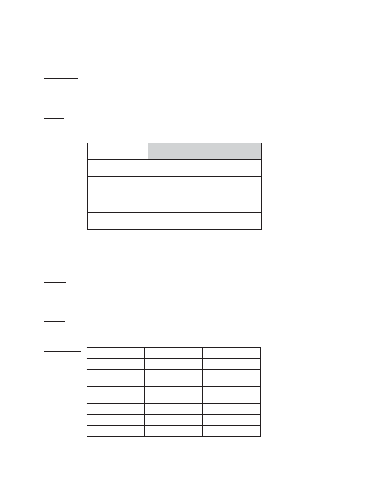
Electrical:
NOITPIRCSED ARUDNE ARUTUF
CAegatloV
gninnuRlatoT
spmA
srotoMevirD
rosserpmoC
V032-802hp1V032-802hp1
0.110.21
hcaePH4/3hcaePH4/3
hUTB006,8HUTB000,21
Use 20 amp HACR circuit breaker.
Automatic safeguard circuit built into electronic control - protects major freezer components under normal operating
conditions.
Cooling
Air cooled requires minimum 3" air clearance on right and left hand side. No clearance needed in the rear.
Water cooled required 3/8" I.D. water supply line and 3/8" I.D. drain line minimum.
Hopper
3 Gallons (11.35 liters) each refrigerated and insulated.
Refrigeration
ledoMG131EG131F
tnaregirfeR A404RA404R
egrahC .zo23C/A
.zo62C/W
fotuotaehrepuS
rotaropavEeht
erusserPnoitcuS *gisp82-42*gisp82-62
erusserPdaeH gisp532-522gisp542-532
erusserPreppoH gisp17-96gisp17-96
Fº62-02Fº61-7
2
.zo24C/A
.zo62C/W
Page 11
SECTION 2
INSTALLATION INSTRUCTIONS
2.1 SAFETY PRECAUTIONS
Do not attempt to operate the freezer until the safety
precautions and operating instructions in this manual
are read completely and are thoroughly understood.
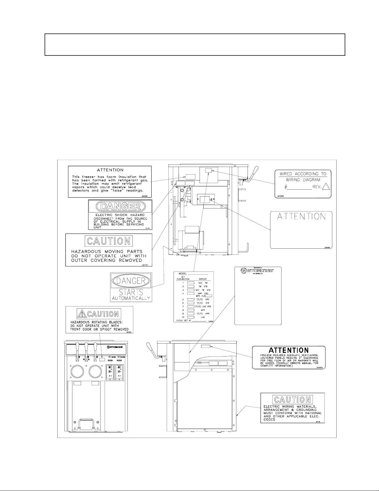
Take notice of all warning labels on the freezer (Fig. 3).
The labels have been put there to help maintain a safe
working environment. The labels have been designed to
withstand washing and cleaning. All labels must remain
legible for the life of the freezer.
Labels should be checked periodically to be sure they
can be recognized as warning labels.
If danger, warning or caution labels are needed, indicate
the part number, type of label, location of label, and
quantity required along with your address and mail to:
STOELTING, INC.
ATTENTION: Customer Service
502 Highway 67
Kiel, Wisconsin 53042-1600
HEAT SENSITIVE THERMISTOR LOCATED
UNDER THIS COVER. TEMPERATURE
MUST NOT EXCEED 220°F NEAR
THERMISTOR. HEAT SINK MUST BE
USED WHEN BRAZING ON EVAPORATOR
OUTLET. CHECK RESISTANCE BEFORE
REMOVAL OF THERMISTOR.
SEE SERVICE MANUAL.
Fig. 3. Warning Label Locations
3
Page 12
2.2 SHIPMENT AND TRANSIT
The freezer has been assembled, operated and
inspected at the factory. Upon arrival at the final
destination, the complete freezer must be checked for
any damage which may have occurred during transit.
With the method of packaging used, the freezer should
arrive in excellent condition. THE CARRIER IS
RESPONSIBLE FOR ALL DAMAGE IN TRANSIT,
WHETHER VISIBLE OR CONCEALED. Do not pay the
freight bill until the freezer has been checked for damage.
Have the carrier note any visible damage on the freight
bill.
If concealed damaged and/or shortage is found later,
advise the carrier within 10 days and request inspection.
The customer must place claim for damages and/or
shortages in shipment with the carrier. Stoelting, Inc.
cannot make any claims against the carrier.
2.3 FREEZER INSTALLATION
C. Air cooled freezers require correct ventilation. The
right side of the freezer is the air intake and must
have a 3" (7.5cm) clearance. Air discharges out of
the left side of the unit and must have 3" (7.5cm)
clearance. Do not obstruct the int ake or discharge
(Fig.4).
CAUTION
FAILURE TO PROVIDE ADEQUATE
VENTILATION WILL VOID WARRANTY!
D. Place the OFF-ON switch in the OFF position.
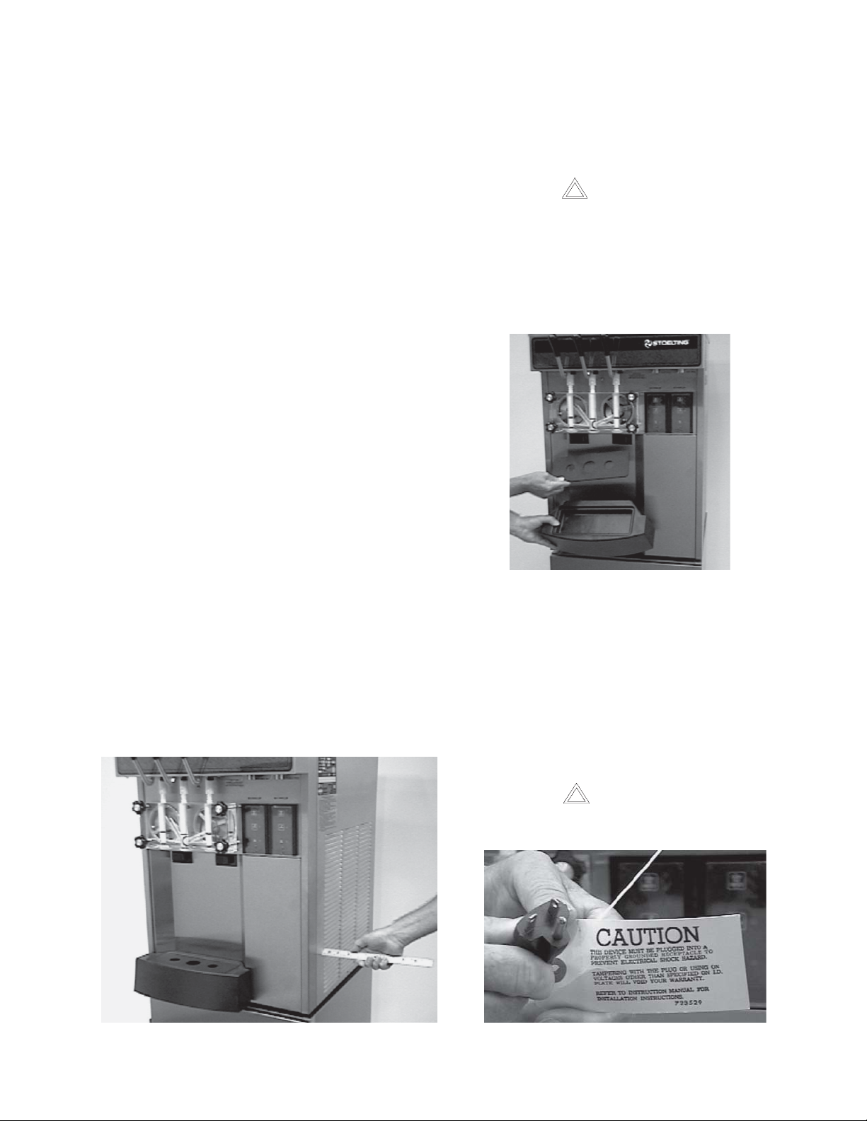
E. Install the drip tray, drain trays, covers and other
miscellaneous parts on the freezer. (Fig. 5)
Installation of the freezer involves moving the freezer
close to its permanent location, removing all crating,
setting in place, assembling parts, and cleaning.
A. Uncrate the freezer.
B. Accurate leveling is necessary for correct drainage
of freezer barrel and to insure correct overrun. Place
a spirit level on top of the freezer at each corner to
check for level condition. If adjustment is necessary ,
level the freezer by turning the bottom part of each
leg in or out. Then separate freezer base gasket and
install with the seam to the back and the flat to the
bottom. (Fig.4).
Figure 5. Installing Tray and Insert
F. Connect the power cord. The plug is designed for
208 or 230 volt/20 amp duty. Check the nameplate
on your freezer for proper supply . The unit must be
connected to a properly grounded receptacle. The
electrical cord furnished as part of the freezer has a
three prong grounding type plug (Fig. 6). The use of
an extension cord is not recommended. If one must
be used, use one with a wire size 12 gauge or heavier
with a ground wire. Do not use an adaptor to get
around grounding requirement.
CAUTION
DO NOT ALTER OR DEFORM PLUG IN ANY
WAY!
Fig. 4. Space and Ventilation Requirements
Figure 6. Power Cord
4
Page 13
2.4 FLOOR STAND INSTALLATION
To install the E/F 131 on to the floor stand, follow the
steps outlined below:
1. Uncrate the floor stand and place in an upright
position.
NOTE
Detailed instructions are included with each floor
stand.
2. Place a spirit level across the top of the stand to
check for level condition, side to side and front to
back. If adjustment is necessary, level the st and by
turning the bottom part of each caster in or out, then
tighten the lock nut, and lock caster.
2.5 INSTALLING PERMANENT WIRING
WARNING
ELECTRICAL TECHNICIANS MUST BE
CONTINUOUSLY ALERT TO THE PRACTICE
OF ALL NECESSARY SAFETY RULES AND
PRECAUTIONS WHEN SERVICING THIS
EQUIPMENT AS VOLTAGES ARE PRESENT
WHICH CAN CAUSE SERIOUS OR FATAL
INJURY.
ELECTRICAL WIRING MATERIALS,
ARRANGEMENT AND GROUNDING MUST
CONFORM WITH NATIONAL AND OTHER
APPLICABLE ELECTRICAL CODES.
3. Remove the four legs from the freezer and replace
with the four leg adapters provided. Adapters must
be fully tightened to the freezer.
4. Place the E/F131 freezer on the floor stand with the
front of the freezer to the door end of the stand.
Secure the freezer to the stand with the nuts and lock
washers provided. Then separate freezer base gasket
and install the seam to the back and the flat to the
bottom (Fig. 7).
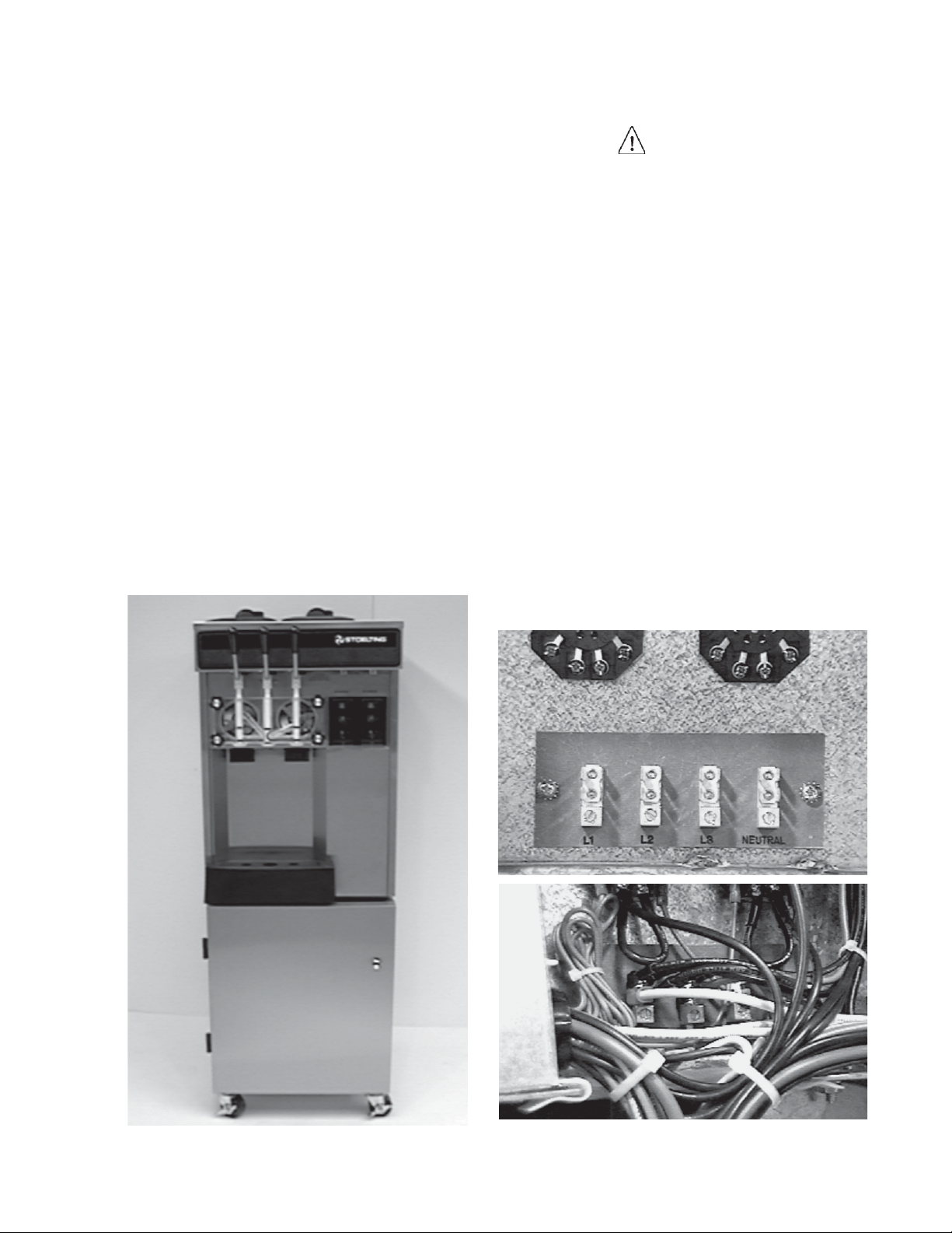
If permanent wiring is required by local codes, the
following procedure must be performed:
A. Remove the back panel.
B. Disconnect the wires from the terminal block. Discon-
nect the green ground wire from the grounding stud.
C. Remove the power cord.
D. Install permanent wiring according to local code.
E. Replace the back panel.
Fig. 7. Floor Stand
Figure 8. Power Cord Connection
5
Page 14

6
Page 15
SECTION 3
INITIAL SET-UP AND OPERATION
3.1 OPERA TOR'S SAFETY PRECAUTIONS
SAFE OPERA TION IS NOT AN ACCIDENT; Observe
these rules:
A. Know the freezer. Read and understand the
Operating Instructions.
B. Notice all warning labels on the freezer.
C. Wear proper clothing. Avoid loose fitting garments,
and remove watches, rings or jewelry which could
cause a serious accident.
D. Maintain a clean work area. Avoid accidents by
cleaning up the area and keeping it clean.
E. Stay alert at all times. Know which switch, push
button or control you are about to use and what
effect it is going to have.
F. Disconnect electrical cord for maintenance.
Never attempt to repair or perform maintenance on
the freezer until the main electrical power has been
disconnected.
G. Do not operate under unsafe operating condi-
tions. Never operate the freezer if unusual or
excessive noise or vibration occurs.
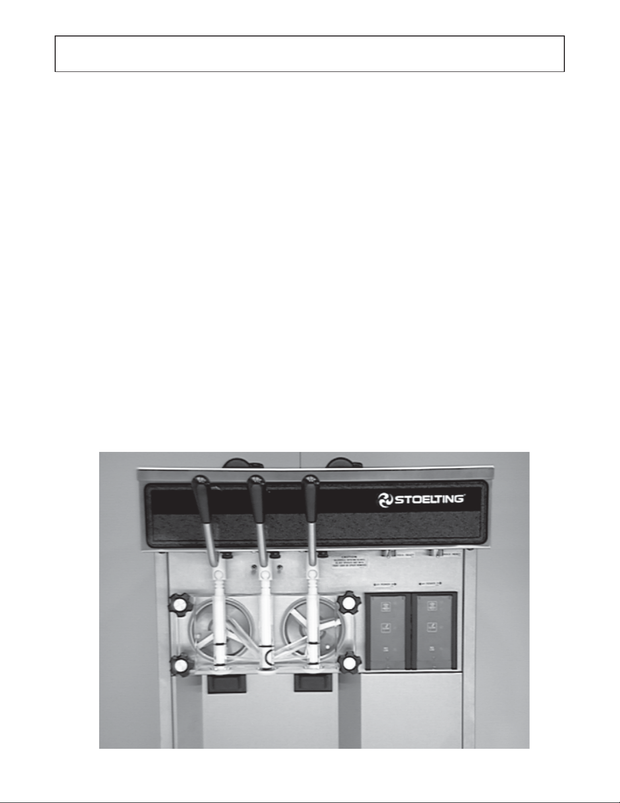
3.2 OPERA TION CONTROLS AND INDICA TORS
Before operating the freezer, it is required that the
operator know the function of each operating
control. Refer to Figure 9 for the location of the
operating controls on the freezer.
WARNING
THE CLEAN-OFF-ON SWITCH MUST BE PLACED
IN THE OFF POSITION WHEN DISASSEMBLING
FOR CLEANING OR SERVICING. THE FREEZER
MUST BE DISCONNECTED FROM ELECTRICAL
SUPPLY BEFORE REMOVING ANY ACCESS
P ANEL.
A. SPIGOT SWITCH
The SPIGOT switch will automatically actuate the
auger drive and refrigeration systems when the spigot
is opened to dispense product. When the spigot is
closed, the drive motor and compressor will remain
“on” until the product in the barrel reaches the proper
consistency.
B. OFF-ON SWITCH
The OFF-ON switch is a two position toggle switch
used to supply power to the control circuit. When the
switch is in the OFF position, nothing will turn. When
the switch is in the ON position, the freezer can be
run in the freezing mode or cleaning mode. the
freezer will be in the idle mode until a switch is
activated.
Figure 9. Controls
7
Page 16

C. PUSH TO FREEZE SWITCH
The PUSH TO FREEZE switch is a "snap" switch
used to start the freezing cycle. During initial freeze
down, the OFF-ON switch is placed in the ON
position. Then the PUSH TO FREEZE switch is
pressed until the drive motor and compressor come
"ON".
NOTE
After the gearmotor starts, there is a 3 second
delay before the compressor starts.
During the normal operation, the red PUSH TO FREEZE
switch light will illuminate after the freezer has been idle
for the preset cycles. Before drawing product, press the
red PUSH TO FREEZE switch if it is illuminated. Wait
until the green light is illuminated before dispensing.
NOTE
If the freezer shuts off and the PUSH TO
FREEZE light flashes, you have an error condition. Turn the OFF-ON switch to the OFF
position, correct the problem and turn the
freezer back on. (See Troubleshooting.)
NOTE
Failure to immediately refill hopper may result in operational problems.
H. HOLD READY SWITCH
The HOLD READY switch is a push button switch.
When pushed in and held for 5 seconds, the hold ready
mode will be activated. The product will remain ready
to serve and the freezer will not go to idle. To return to
normal operation push and hold for 5 seconds.
I. HIGH PRESSURE CUTOUT
The HIGH PRESSURE CUTOUT switch is a safety
switch designed to protect the compressor from damage due to excessive head pressure. When tripped,
the lever will be out, push in to reset.
J. DISPENSE RATE ADJUSTER
The DISPENSE RATE ADJUSTER limits the opening
of the spigot.
To adjust product dispense rate, turn the adjusting
knobclockwise for slower flow and counterclockwise
for faster flow.
D. GREEN LIGHT
The green light is used to indicate that the product
has reached the proper consistency and is ready to
be dispensed. The light begins to flash at 98% of
consistency.
NOTE
If the PUSH TO FREEZE red light is illuminated,
push the PUSH TO FREEZE switch and wait
until the green light illuminates before dispensing.
E. CLEAN SWITCH
The CLEAN switch is a "snap" switch. When the switch
is pushed the refrigeration system will be OFF and the
auger will rotate for cleaning. When the switch is
pushed again, the auger will stop and the CLEAN light
will flash indicating the freezer is in the CLEAN mode.
To exit the CLEAN mode turn the OFF-ON switch to
the OFF position. If the freezer is left in CLEAN for
more than 30 minutes or is pushed three times in ten
seconds, it will go in error.
F. DRIVE MOTOR OVERLOAD
The internal drive motor overload will trip if the drive
motor is overloaded. It will reset after approximately
10-12 minutes. If the drive motor continues to trip,
refer to Section 4-Troubleshooting.
G. RED MIX LOW LENS
The red MIX LOW light is designed to alert the
operator to a low mix condition. The lens will illumi-
nate with approximately one gallon of mix in the
hopper. When the MIX LOW lens is lit, refill hopper
immediately .
K. DOOR INTERLOCK SWITCH
When the door is securely fastened, the freezer will
operate normally . When the door is removed, the
drive and compressor will not run.
3.3 SANITIZING
Sanitizing must be done after the freezer is clean and
just before the hopper is filled with mix. Sanitizing the
night before is not effective. However, you should
always clean the freezer and parts after using it.
WARNING
THE UNITED STATES DEPARTMENT OF AGRICULTURE AND THE FOOD AND DRUG ADMINISTRATION
REQUIRE THAT ALL CLEANING AND SANITIZING SOLUTIONS USED WITH FOOD PROCESSING EQUIPMENT BE CERTIFIED FOR THIS USE.
When sanitizing the freezer, refer to local sanit ary
regulations for applicable codes and recommended
sanitizing products and procedures. The frequency of
sanitizing must comply with local health regulations. Mix sanitizer according to manufacturer’s instruc-
tions to provide a 100 parts per million strength solution.
Mix sanitizer in quantities of no less than 2 gallons (7.5
liters) of 120°F of water. Allow sanitizer to contact the
surfaces to be sanitized for 5 minutes. Any sanitizer
must be used only in accordance with the
manufacturer’s instructions.
CAUTION
PROLONGED CONTACT OF SANITIZER WITH FREEZER
MAY CAUSE CORROSION OF STAINLESS STEEL
PARTS.
8
Page 17
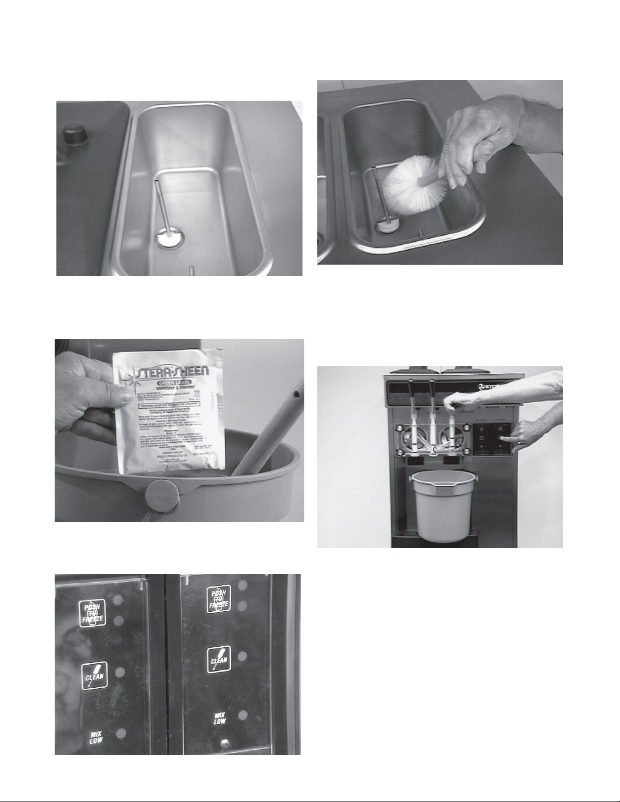
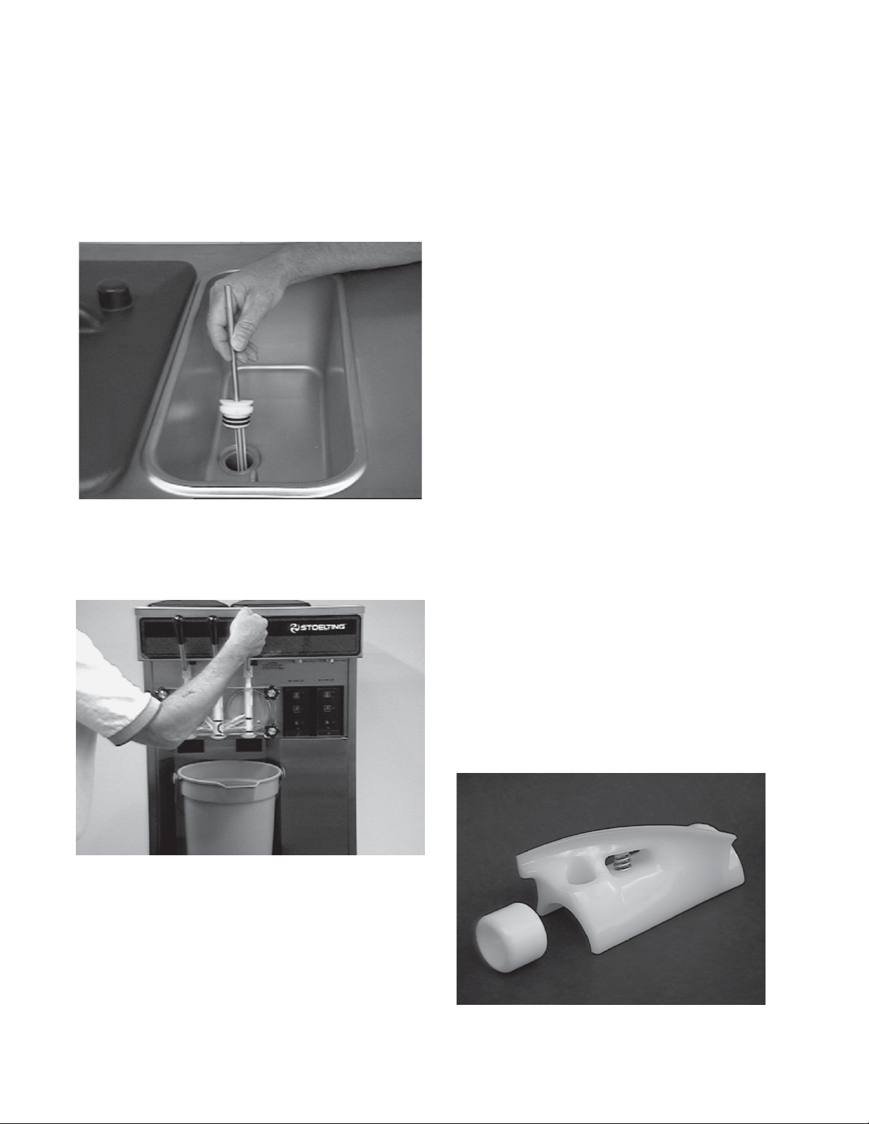
In general, sanitizing may be conducted as follows:
A. Push the mix inlet regulator into hopper with air inlet
(long) tube toward the front of the freezer.
(Fig. 10).
Figure 10. Mix Inlet Regulator
B. Prepare 2 gallons (7.5 liters) of sanitizing solution
following manufacturer’s instructions. Pour into
hopper with mix inlet regulator in place (Fig. 1 1).
D. Clean sides of hopper, mix inlet regulator and under-
side of hopper cover using a sanitized soft bristle
brush dipped in the sanitizing solution (Fig. 13).
Figure 13. Sanitizing Hopper
E. After five minutes, place a bucket under the spigot
and open spigot to drain sanitizing solution. When
solution has drained, press the CLEAN snap switch
to stop the auger. Allow the freezer barrel to drain
completely (Fig. 14).
Figure 11. Sanitizing Procedure
C. Place the OFF-ON toggle switch in the ON position
while pressing the CLEAN switch. Check for leaks.
Figure 12. Clean Control
Figure 14. Spigot Opened and Solution Draining
3.4 FREEZE DOWN AND OPERA TION
This section covers the recommended operating procedures to be followed for the safe operation of the freezer.
A. Sanitize just prior to use.
B. Place the OFF-ON switch in the OFF position.
C. With spigots open, pour approximately 1 gallon (3.8
liters) of mix into the hopper. Allow the mix to flush
out about 8 ounces (0.23 liters) of sanitizing solution
and liquid mix. Close the spigot.
9
Page 18
D. Fill hopper with approximately 3 gallons (11.4 liters)
o f prechilled (40°F or 4°C) mix.
CAUTION
DO NOT OVERFILL THE HOPPER. MIX LEVEL MUST
NOT BE HIGHER THAN 2 INCHES (5 CM) FROM THE TOP
OF THE AIR INLET TUBE ON THE MIX INLET REGULATOR.
E. The freezer barrel will automatically fill until it is
about 1/2 full. If freezer barrel does not fill, check for
obstruction in the mix inlet regulator. If freezer barrel
fills over 1/2 full, indicated by low overrun, check for
leaks at the mix inlet regulator "O" Ring or check if
the mix inlet regulator was installed correctly or that
the freezer is level.
F. Place the OFF-ON switch in the ON position, then
press the PUSH TO FREEZE swtich until the freezer
starts.
NOTE
After the gearmotor starts, there is a 3 second
delay before the compressor starts.
G. After about 6 to 10 minutes the freezer will shut off
and the green lens will illuminate. The product will be
ready to serve. Freeze down time may be longer for
some frozen diet dessert mixes. High ambient
temperatures may extend freeze down time.
H. For normal dispensing, move the spigot handle fully
open (Fig. 15).
I. The freezer is designed to dispense the product at a
reasonable draw rate. If the freezer is overdrawn, the
result is a soft product or a product that will not
dispense at all. If this should occur , allow the freezer
to run for approximately 30 seconds before dispensing additional product. After a while the operator will
sense or feel when the freezer is beginning to fall
behind, and will slow down on the rate of draw so as
not to exceed the capacity.
J. Do not operate the freezer when the MIX LOW light
ison or with less than 1-3/4" (4.4 cm) of mix in the
hopper. Refill the hopper immediately .
NOTE
The freezer has a standby mode sometimes
referred to as a sleep or energy conservation
mode. When the freezer is not used, after a
preset time, it will enter the standby mode and
remain there until someone draws a product or
pushes the push-to-freeze switch. In the
standby mode, the freezer will keep the product
below 45°F . S t andby modes are not to be used
in place of cleaning and sanitizing. Frequency of
cleaning and sanitizing is determined by Federal, State, and local regulatory agencies.
3.5 MIX INFORMA TION
Mix can vary considerably from one manufacturer to
another. Differences in the amount of butterfat content
and quantity and quality of other ingredients have a
direct bearing on the finished frozen product. A change
in freezer performance that cannot be explained by a
technical problem may be related to the mix.
Figure 15. Dispensing Product
CAUTION
REFRIGERATION IS AUTOMATICALLY
ACTIVATED WHEN THE SPIGOT IS OPENED.
CLOSE THE SPIGOT COMPLETELY AFTER
DISPENSING.
When changing from one type of mix to another such as
yogurt to Vitari, you may have to change the mix inlet
regulator and/or control settings. Please call your
distributor for further information.
Proper product serving temperature varies from one
manufacturer’s mix to anther. Mixes should provide a
satisfactory product in the 18° to 20°F (-7° to -6°C)
range.
When checking the temperature, stir the thermometer in
the frozen product to read the true temperature.
Mix does not improve with age. Old mix, or mix that has
been stored at too high a temperature, can result in a
finished product that is less than satisfactory in taste
and appearance. T o ret ard bacteria growth in dairy based
mixes, the best storage temperature range is between
36° to 40°F (2.2° to 4.4°C).
Some products tend to foam more than others. If excess
foam should occur, skim the foam off with a sanitized
utensil and discard. Periodically , stir the mix in the
hopper with a sanitized utensil.
10
Page 19
3.6 REMOVING MIX FROM THE FREEZER
T o remove the mix from the freezer , refer to the following
steps:
After the mix has been removed from the freezer , the
freezer must be cleaned. T o clean the freezer , refer to the
following steps:
A. Remove the mix inlet regulator from the hopper by
pulling straight up (Fig.16).
B. Place the OFF-ON rocker switch in the ON position
and push the CLEAN switch to rotate the auger.
Allow the mix to agitate in the freezer barrel until the
mix has become a liquid, about 5 minutes.
Figure 16. Removing Mix Inlet Regulator
C. Drain the liquid mix by opening the spigot. A bucket
or container should be placed under the spigot to
catch the liquid mix (Fig. 17).
A. Close the spigot and fill the hopper with 2 gallons
(7.5 liters) of cold tap water.
B. Place the OFF-ON switch in the ON position while
pushing the CLEAN switch to rotate the auger .
C. Allow the water to agitate for approximately five
minutes.
NOTE
If freezer is left in CLEAN for more than 30
minutes, it will go to error.
D. Open the spigot to drain the water. Remember to
place a bucket or container under the spigot to catch
the water. When the water has drained, turn the
OFF-ON switch to the OFF position. Allow the freezer
barrel to drain completely .
E. Repeat steps A through D using a mild detergent
solution.
3.8 DISASSEMBL Y OF FREEZER P ARTS
CAUTION
PLACE THE OFF-ON TOGGLE SWITCH IN THE OFF
POSITION BEFORE DISASSEMBLING FOR CLEANING
OR SERVICING.
Figure 17. Draining Mix
D. Place the OFF-ON switch in the OFF position.
3.7 CLEANING THE FREEZER
NOTE
The frequency of cleaning the freezer and freezer
parts must comply with local health regulations.
Inspection for worn or broken parts should be made at
every disassembly of the freezer for cleaning or other
purposes. All worn or broken parts should be replaced to
ensure safety to both the operator and the customer and
to maintain good freezer performance and a quality
product. T wo normal wear areas are the auger flights and
front auger support bushing (Fig. 18). Frequency of
cleaning must comply with the local health regulations.
Figure 18. Auger Flight Wear and Front Auger
Support Bushing Wear
11
Page 20
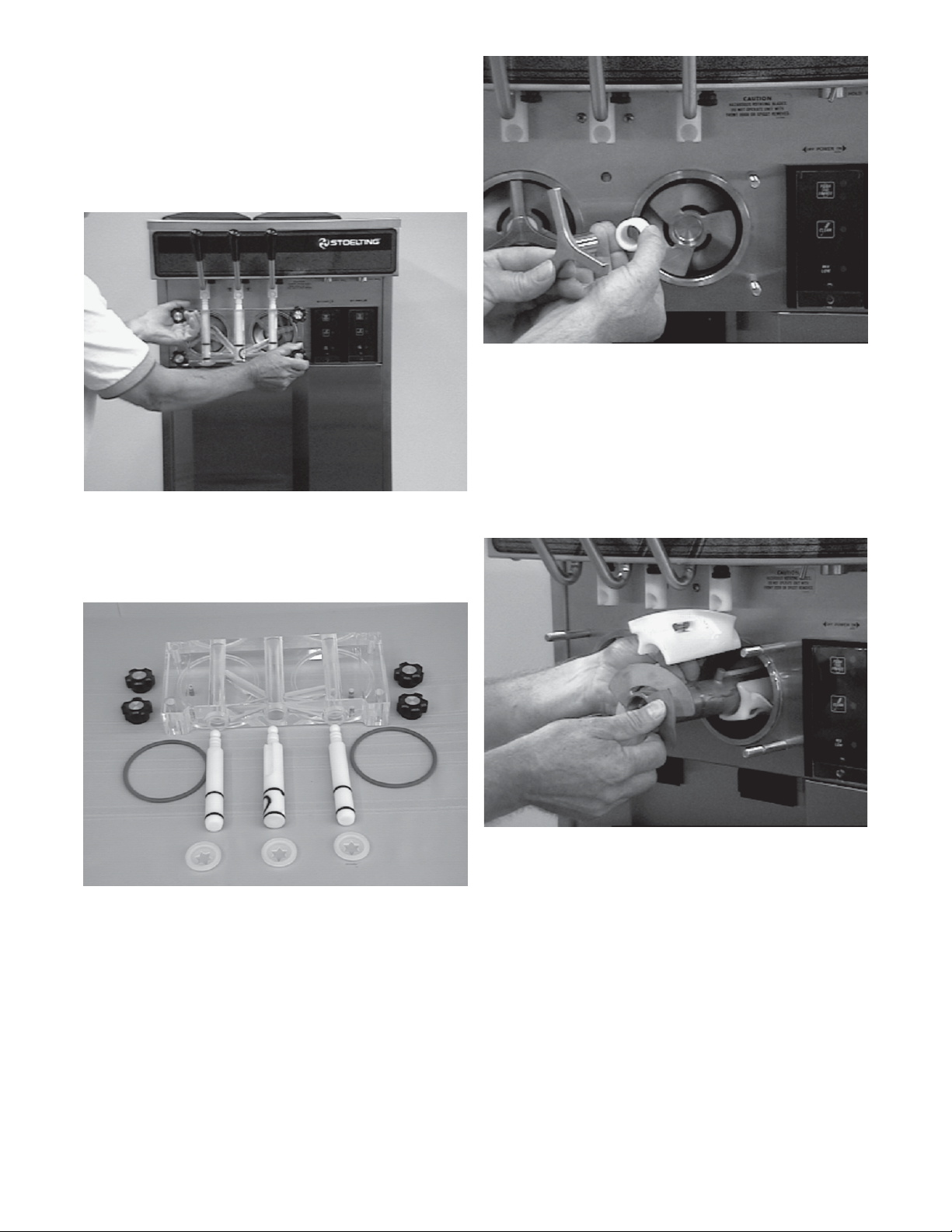
T o disassemble the freezer , refer to the following steps:
A. Remove the mix inlet regulator from the hopper by
pulling straight up.
B. Remove the front door by turning off the circular
knobs and then pulling the front door off the studs
(Fig.19).
Figure 19. Removing Front Door
C. Remove the rosette caps from the front door. Push
the spigot body through the bottom of the front door
and remove. (Fig. 20).
Figure 21. Removing Auger Supports
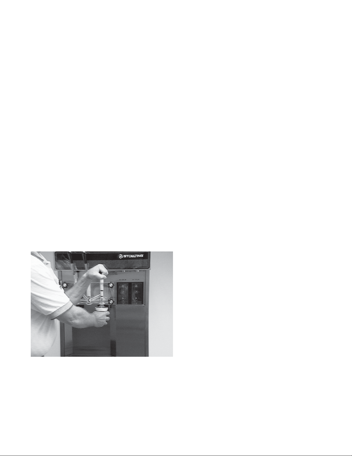
E. Remove the auger assemblies from the freezer. Pull
the augers out of the freezer barrel slowly. As the
augers are being pulled out, carefully remove each of
the plastic flights with springs.
F. Keep the rear of the auger shafts tipped up once they
are clear of the freezer barrels to avoid dropping rear
seals (Fig. 22.)
Figure 20. Front Door Disassembly
D. Remove the front auger supports and bushings
(Fig. 21).
Figure 22. Auger Shafts
G. Wipe socket lubricant from the drive end (rear) of the
auger with a cloth or paper towel.
H. Remove the rear seals.
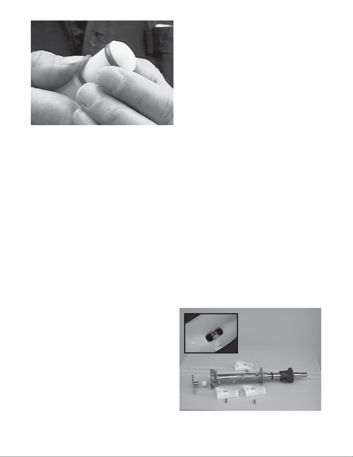
I. Remove all "O" Rings from parts by first wiping off the
lubricant using a clean paper towel. Then squeeze the
"O" Ring upward with a dry cloth (Fig. 23). When a loop
is formed, roll out of the "O" Ring groove.
12
Page 21
B. Place all parts in the sanitizing solution, then remove
and let air dry .
C. Using this sanitizing solution and the large barrel
brush provided, sanitize the rear of the barrel and
drive area by dipping the brush in the sanitizing
solution and brushing the rear of the barrel.
3.11 ASSEMBL Y OF FREEZER
T o assemble the freezer parts, refer to the following
steps:
NOTE
Petrol-Gel sanitary lubricant or equivalent must
be used when lubrication of parts is specified.
Figure 23. Removing "O" Ring
WARNING
DO NOT USE ANY TYPE OF SHARP OBJECT TO
REMOVE THE O-RINGS.
3.9 CLEANING THE FREEZER P ARTS
Place all loose parts in a pan or container and take to
the wash sink for cleaning. To clean freezer parts refer to
the following steps:
A. Place all parts in warm mild detergent water and
clean with brushes provided. Rinse all parts with
clean hot water.
CAUTION
DO NOT DAMAGE PARTS BY DROPPING OR ROUGH
HANDLING.
B. Wash the hopper and freezer barrel with warm
detergent water and brushes provided.
C. Clean the rear seal surfaces from the inside of the
freezer barrel with warm detergent water.
NOTE
The United States Department of Agriculture and
Food and Drug Administration require that
lubricants used on food processing equipment
be certified for this use. Use lubricants only in
accordance with the manufacturer’s instructions.
A. Assemble all o-rings onto parts dry, without lubrica-
tion. Then apply a thin film of sanitary lubrication to
exposed surfaces of the "O" Rings. Apply a thin film
o f sanitary lubricant to metal part of rear seal. Also
apply a thin film of sanitary lubricant inside the hole
of the front of the auger .
B. Assemble the rear seals onto the augers with the
large end to the rear . Be sure the "O" Ring is in place
before installing the rear seal.
C. Lubricate the inside of the auger drive sockets (rear)
with a small amount of white socket lubricant. A
small container of socket lubricant is shipped with
the freezer.
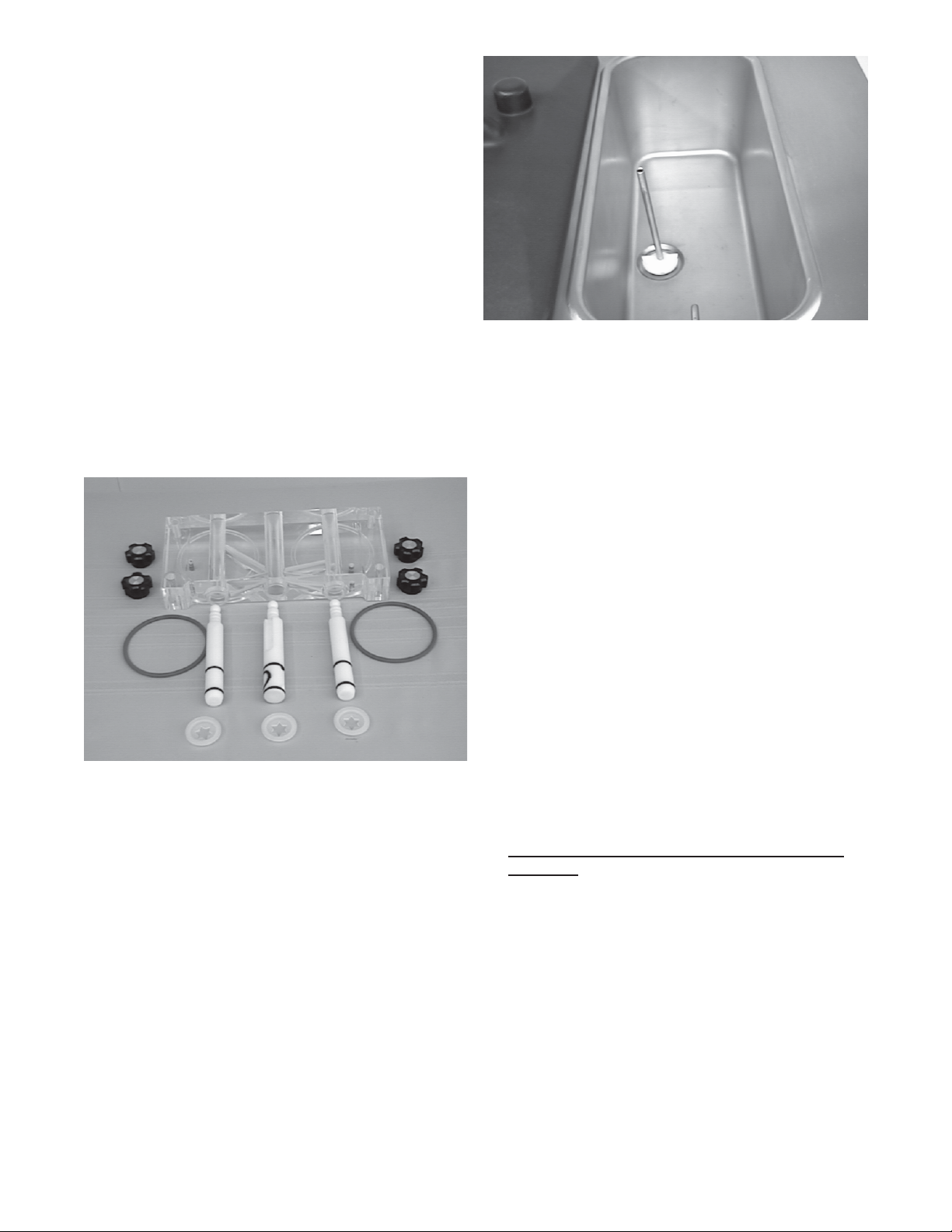
D. Screw the springs onto the studs in plastic flights.
Springs must be screwed into the flights com
pletely to provide compression (Fig. 24).
NOTE
Clean the auger drive socket located inside the
barrel at the rear seal area. Use clean cloth or
paper towel for this purpose.
D. Clean the drip tray and insert with a soap solution.
Rinse with clean hot water.
3.10 SANITIZE FREEZER AND FREEZER P ARTS
A. Use a sanitizer mixed according to manufacturer’s
instructions to provide a 100 parts per million
strength solution. Mix sanitizer in quantities of no
less than 2 gallons (7.5 liters) of 120°F water. Allow
the sanitizer to contact the surfaces to be sanitized
for 5 minutes. Any sanitizer must be used only in
accordance with the manufacturer’s instructions.
Figure 24. Exploded View of Auger
13
Page 22
CAUTION
DO NOT PLACE THE MIX INLET REGULA TOR INTO
THE HOPPER BEFORE INSTALLING THE AUGER.
E. Install the two plastic flights onto rear of the auger
and insert part way into freezer barrel.
F. Install the third plastic flight, push the auger into the
freezer barrel and rotate slowly until the auger
engages the drive socket.
G. Install the auger support and bearing into the front of
the augers with one leg of the support at 9 o’clock.
NOTE
Apply a small amount of Petro-Gel to the
surface of the cam on the spigot handle prior to
assembly of handle to the spigot body .
H. Install the spigot bodies with "O" Rings into the front
door from the bottom (Fig.25). Push straight up until
the spigots are in place. Install rosette caps.
Figure 25. Exploded View of Front Door
I. Install the front door on the freezer .
Figure 26. Install Mix Inlet Regulators
3.12 ROUTINE CLEANING
T o remove spilled or dried mix from the freezer exterior ,
simply wash in the direction of the finish with warm
soapy water and wipe dry. Do not use highly abrasive
materials as they will mar the finish.
3.13 PREVENTIVE MAINTENANCE
It is recommended that a maintenance schedule be followed to keep the freezer clean and operating properly.
A. Cleaning and Sanitizing Information
Soft serve freezers require special consideration
when it comes to food safety and proper
cleaning and sanitizing.
The following information has been compiled
by Purdy Products Company, makers of SteraSheen Green Label Cleaner/Sanitizer and specifically
covers issues for cleaning and sanitizing frozen
dessert machines. This information is meant to
supplement a comprehensive food safety program.
J. Install the circular knobs on the freezer studs.
CAUTION
FINGER TIGHTEN THE CIRCULAR KNOBS
EVENL Y . DO NOT OVERTIGHTEN KNOBS.
Look for the proper seal between the freezer barrel, "O"
Ring, and front door.
K. Install the mix air regulator into the freezer with the
air tube to the front of the freezer. (Fig. 26).
NOTE
Refer to page 3-2, section 3.3, for sanitizing the
assembled freezer before filling with mix.
Soil Materials Associated with Frozen Dessert
Machines
MILKFAT/BUTTERFAT – As components of icecream/frozen custard mix, these soils will
accumulate on the interior surfaces of the machine
and its parts. Fats are difficult to remove and help
attribute to milkstone build-up.
MILKSTONE – Is a white/gray film that forms on
equipment and utensils that come in contact
with dairy products. These films will accumulate
slowly on surfaces because of ineffective
cleaning, use of hard water, or both. Milkstone
is usually a porous deposit, which will harbor
microbial contaminants and eventually defy sanitizing
efforts.
14
Page 23

Once milkstone has formed, it is very difficult to
remove. Without using the correct product and
procedure, it is nearly impossible to remove a thick
layer of milkstone.
(NOTE: general-purpose cleaners DO NOT remove
milkstone.) This can lead to high bacteria counts
and a food safety dilemma.
IT IS BEST TO CONTROL MILKSTONE ON A
DAILY BASIS BEFORE IT CAN BECOME A
SIGNIFICANT FOOD SAFETY PROBLEM.
In addition to food safety, milkstone can cause
premature wear to machine parts which can add to
costs for replacement parts or possibly more
expensive repairs if worn machine parts are not
replaced once they have become excessively worn.
Important Differences Between Cleaning and
Sanitizing
CLEANING vs. SANITIZING
It is important to distinguish between cleaning and
sanitizing. Although these terms may sound
synonymous, they are not. BOTH are required for
adequate food safety and proper machine
maintenance.
CLEANING
· Is the removal of soil materials from a surface.
· Is a prerequisite for effective sanitizing.
NOTE
An UNCLEAN surface will harbor bacteria that can
defy sanitizing efforts.
Proper Daily Maintenance: The Only Way to
Assure Food Safety and Product Quality
Proper daily maintenance can involve a wide variety
of products and procedures. Overall, the products
and procedures fall into three separate categories.
(Please note that this is a brief overview intended for
informational purposes only.)
1. CLEANING – This involves draining mix from the
freezer barrel and rinsing the machine with water.
Next, a cleaner is run through the machine. Then,
the machine is disassembledand removable parts
are taken to the sink for cleaning.
2. MILKSTONE REMOVAL – Since almost all cleaners
do not have the ability to remove milkstone, the use
of a delimer becomes necessary. Although this
procedure may not be needed on a daily basis, it will
usually follow the cleaning procedure. It requires
letting a delimer solution soak in the machine for an
extended period of time. Individual parts are also
soaked in a deliming solution for an extended period
of time (more about delimers in Additional
Information).
3. SANITIZING – After the machine has been cleaned
and contains no milkstone, the machine is
reassembled. Then a FDA-approved sanitizing
solution is run through the machine to kill bacteria.
The machine is then ready for food preparation.
As a recommended cleaner and sanitizer for your
frozen dessert machine, STERA-SHEEN has proven
to be one of the best daily maintenance products for:
· CLEANING – Thorough removal of all solids
including butterfat and milk fat.
Bacteria can develop and resist sanitizing efforts
within a layer of soil material (milkstone). Thorough
cleaning procedures that involve milkstone
removal are critical for operators of frozen
dessert machines.
SANITIZING
· Kills bacteria.
· Can be effective on clean surfaces only.
· DOES NOT clean or remove milkstone.
NOTE
Using a SANTITIZER on an unclean surface
will not guarantee a clean and safe frozen
dessert machine.
· MILKSTONE REMOVAL – Complete removal of
milkstone.
· SANITIZING – FDA-approved no rinse sanitizer
for food contact surfaces.
Additional Information
THE USE OF DELIMERS
A delimer is a strong acid that has the ability to
dissolve milkstone. This type of chemical may
become necessary once high levels of milkstone
have developed. While these products are very
effective for removing HIGH levels of milkstone, they
are not ideal for two reasons:
15
Page 24

1. PRODUCT SAFETY – Strong acids are
dangerous chemicals and handling them
requires safety.
Sanitizing solutions should not be allowed to fall below
100 ppm chlorine. New solutions should be mixed once
old solutions become ineffective.
2. MACHINE DAMAGE – Strong acids will attack
metal and rubber causing premature wear of
parts. The use of a delimer needs to be closely
monitored to avoid damage to machine surfaces
and parts.
With proper daily use of STERA-SHEEN or it’s
equivalent, there is no need for the use of a DELIMER.
DO NOT USE BLEACH
· BLEACH HAS ABSOLUTELY NO CLEANING
PROPERTIES.
· BLEACH IS CORROSIVE. It can and will
damage components of the machine causing
premature wear and metal corrosion.
GENERAL PURPOSE CLEANERS
General purpose cleaners do not have the ability to
remove milkstone. Milkstone will become a problem
if not remedied with additional products and
procedures.
W ARNING
NEVER ATTEMPT TO REPAIR OR PERFORM
MAINTENANCE ON FREEZER UNTIL THE MAIN
ELECTRICAL POWER HAS BEEN
DISCONNECTED.
B. DAILY
1. The exterior should be kept clean at all times to
preserve the lustre of the stainless steel. A mild
alkaline cleaner is recommended. Use a soft
cloth or sponge to apply the cleaner.
CAUTION
DO NOT USE ACID CLEANERS, STRONG
CAUSTIC COMPOUNDS OR ABRASIVE
MATERIALS TO CLEAN ANY PART OF THE
FREEZER EXTERIOR OR PLASTIC P ARTS.
C. WEEKLY
1. Check "O" Rings and rear seal for excessive
wear and replace if necessary.
THE USE OF CHLORINE TEST STRIPS
“Test strips” are used to determine concentrations of
active chlorine in sanitizing solutions. To use the strips,
tear off a small portion and submerge it into the
sanitizing solution. Then, compare the color change to
the color key on the side of the test strip dispenser to
determine the approximate chlorine concentration.
The ideal concentration of chlorine needs to be 100 ppm
(as stated by the FDA).
NOTE
Follow the directions on the container for proper
concentration.
There are two main factors that contribute to falling
chlorine concentrations in a sanitizing solution.
1. PRODUCT USE – As the chlorine in the
solution is being used, chlorine concentrations
fall.
2. Remove the drip tray by gently lifting up to
disengage from the support and pulling out.
Clean behind the drip tray and front of the
freezer with a soap solution.
2. TIME – As time passes, small amounts of
chlorine “evaporate” from the solution. (That is
why you can smell it.)
16
Page 25

SECTION 4
REFRIGERATION SYSTEM
WARNING
BOTH SUCTION SIDE SOLENOIDS MUST BE
ACTIVATED FOR PROPER PURGING OF
SYSTEM. USE POWER CORD P ART NUMBER
430119 OR EQUIVALENT FOR DIRECT
CONNECTION.
4.1 REFRIGERATION SYSTEM
The refrigeration system (Fig.27) is a dual-purpose
system.
Figure 27. Refrigeration System
17
Page 26

The system is designed to operate both the hopper and
evaporator simultaneously at different temperatures.
The system is designed for efficient use with R404A as
the refrigerant. The proper charge is indicated on the
nameplate and on the compressor.
The compressor has an internal high-pressure bypass.
This bypass eliminates the need for a high-pressure
cutout switch on air-cooled models. Water-cooled models
must have a high-pressure cutout switch.
4.2 EVAPORATORS
The hopper and barrel evaporators are wrapped with
copper tubing and thermomastic, then insulated with
foam insulation. The compressor is designed specifically
for use with R404A.
3. Remove wires C, R, and S at compressor. Refer to
Figure 29 for compressor connections.
4.3 COMPRESSOR WINDING TEST
To test the compressor motor windings for possible
problems, perform the following steps:
Warning
DISCONNECT FREEZER FROM ELECTRICAL
SUPPLY SOURCE BEFORE SERVICING.
1. Remove the Phillips head screw from the bottom of
the left side panel and slide the side panel down and
out.
2. Remove the compressor terminal cover by inserting
a standard screwdriver between the terminal cover
and compressor cover frame: then, gently pry off from
the right side, then the left (Figure 28).
Figure 29. Compressor Connections
NOTE
The following values are average for most
Copeland compressors. For exact values or other
brands, consult the manufacturer’s service data
manual.
4. Connect an ohmmeter to terminals C and R.
Resistance through the run winding should be 3.12
to 3.60 ohms with the ohmmeter set at ohms x 1
(Figure 30).
Figure 28. Compressor Terminal Cover
Figure 30. Ohmmeter and Connections
18
Page 27

5. Connect the ohmmeter to terminals C and S.
Resistance through the start winding should be 7.77
to 8.93 ohms with the ohmmeter set at ohms x 1.
ventilation on the right and left sides of the unit for free flow
of air (Figure 32). Make sure the freezer is not pulling over
100° F (37° C) air from other equipment in the area.
6. T o check if windings are shorted to ground, connect
one ohmmeter lead to a bare metal part on the
compressor, such as any copper line leading to or
from the compressor and checking terminals C, R,
and S.
NOTE
The compressor is equipped with an internal
overload protector. If the compressor is warm and
ohmmeter reads indicate an open winding, and
allow up to one hour for the overload to reset.
To access the compressor starting components, remove
the Phillips head screw from the bottom of the right side
panel and remove the panel by pulling down and out.
Then, remove the cover from the lower electrical box
located just above the condenser on the right side of the
freezer (Figure 31).
The water-cooled condenser is a tube and shell type.
The condenser needs a cool, clean supply of water to
properly cool the freezer, Inlet and discharge lines must
be 3/8” I.D. minimum.
Figure 31. Electrical Box Cover Removal
4.4 CONDENSERS
The air-cooled condenser is a copper tube and aluminum
fin type. Condensing is totally dependent upon airflow.
A plugged condenser filter, condenser, or restrictions in
the louvered panel will restrict airflow. This will lower the
capacity of the system and damage the compressor.
The condenser must be kept clean of dirt and grease.
The freezer must have a minimum of 3” (7.5 cm) of
Figure 32. Condenser and Filter
The condenser and condenser filter require periodic
cleaning. To clean, refer to the following procedures.
WARNING
DISCONNECT FREEZER FROM ELECTRICAL
SUPPLY SOURCE BEFORE SERVICING.
1. Remove the Phillips head screw from the bottom of
the right side panel, and then slide the panels down
and out.
2. To remove the condenser filter, grasp the top and
pull off. Visually inspect for dirt. If the filter is dirty,
shake or brush excess dirt off the filter and wash in
warm, soapy water. Once the filter is clean rinse
thoroughly in warm, clear water and shake dry , taking
care not to damage the filter in any way .
3. Visually inspect the condenser for dirt by shining a
light through the coil from the back (inside) of the
condenser (Figure 33).
19
Page 28

4.5 T.X.V.
A T.X.V. (Thermostatic Expansion Valve) (Figure 34)
is used to meter the refrigerant to the evaporator. The
self-regulating T.X.V. is preset at the factory.
Figure 34. T.X.V. (Thermostatic Expansion Valve)
Figure 33. Condenser Inspection
4. If the condenser is dirty, place a wet towel over the
front (outside) of the condenser.
5. Using compressed air or a CO2 tank, blow out the
dirt from the back (inside) of the condenser. Most of
the dirt will cling to the wet towel.
NOTE
This procedure will result in a very loud noise.
6. An alternative method of cleaning the condenser is
to use a condenser brush and vacuum.
NOTE
If the condenser is not kept clean, loss of
refrigeration efficiency will result; causing
extended run time or soft product consistency .
Water-cooled condensers need an unrestricted
supply of cold, clean water.
4.6 T.X.V. ADJUSTMENT
T.X.V. adjustment is not recommended. Any attempt
to adjust the T.X.V. will cause the freezer to be totally
out of calibration.
4.7 T.X.V. REMOVAL
CAUTION
IF A T.X.V. REPLACEMENT IS NEEDED, A
HEA TSINK (WET CLOTH) MUST BE USED TO
PREVENT DAMAGE TO THE V AL VE.
WARNING
DISCONNECT FREEZER FROM ELECTRICAL
SUPPLY SOURCE BEFORE SERVICING.
1. Remove the two Phillips head screws from the bottom
of the front and side panels then slide the panels
down and out (Figure 35).
2. Remove the bulb from the suction line exiting from
the evaporator (Figure 35).
20
Page 29

Figure 35. Bulb Removal
3. Recover the refrigerant charge, and then leave a port
open to prevent pressure buildup when applying heat.
WARNING
BOTH SUCTION SIDE SOLENOIDS MUST BE
ACTIVATED FOR PROPER PURGING OF
SYSTEM. USE POWER CORD PART NO.
430119 OR EQUIVALENT FOR DIRECT
CONNECTION.
7. Unsweat the suction line and liquid line from the T .X.V .
and remove.
4.8 T.X.V. INSTALLATION
To replace the T.X.V., perform the following procedures:
CAUTION
WHEN PLACING THE T .X.V ., A HEA TSINK (WET
CLOTH) MUST BE USED TO PREVENT
DAMAGE TO THE V ALVE.
1. Position the T .X.V . with heatsink so the liquid line and
suction line correspond with the proper valve ports.
2. Braze the liquid line and suction line to the T .X.V. by
using the appropriate brazing material.
3. Remove the heatsink from the T.X.V .
4. Replace any foam insulation to the surrounding lines.
5. Replace any insulation to the T .X.V . and surrounding
areas.
4. Remove any insulation from the T .X.V . and immediate
surrounding lines.
5. Remove or push back any foam insulation from
surrounding lines.
6. Apply a heatsink (wet cloth) to the valve dome (Figure
36).
NOTE
The liquid line from the condenser is bonded to
the suction line to provide a heat exchange to help
protect the compressor from liquid slugging. This
also assures that sub-cooled liquid is being
supplied to the expansion devices.
Figure 36. T.X.V. Removal
21
Page 30

6. Install the bulb on the suction line exiting the
evaporator (Figure 37). The T .X.V . bulb should always
be mounted on the top of the horizontal line. Good
contact between the bulb and suction line is
necessary for proper operation of the valve. The bulb
must also be well insulated.
Figure 37. Bulb Installation
4.9 HOPPER
A parallel refrigeration circuit feeds the hoppers. A
capillary tube is used to meter the refrigerant to each
hopper. An E.P.R. (Evaporator Pressure Regulating)
valve is used to control the refrigerant flow at the outlets.
The E.P.R. valve controls the hopper pressure so during
heavy dispensing periods, hopper temperatures will not
drop and freeze the mix in the hopper. The adjustable
E.P.R. valve is preset at the factory. If the hopper
temperature is too cold or too warm, an E.P.R. valve
adjustment may be necessary.
4.10 E.P.R. VALVE ADJUSTMENT
To adjust the E.P.R. valve, refer to the following
procedures:
1. Remove the Phillips head screws from the bottom of
the front panel and remove the panel by sliding down
and out.
7. Replace filter drier using the appropriate brazing
material (Figure 38).
Figure 38. Filter Dryer
8. Once the T.X.V. and filter drier are installed, the
refrigeration system must be leaked checked, purged
and evacuated to 500 microns of mercury or less at
either barrel outlet access fitting proceeding suction
line solenoid valves.
2. Remove the cap from the E.P.R. Schrader access
fitting (Figure 39).
Figure 39. E.P.R. Schrader Access Fitting
3. Install a 0-100 P.S.I.G. gauge onto the E.P.R.
Schrader access fitting.
4. Start the refrigeration cycle and read the pressure.
22
Page 31

NOTE
The ideal E.P .R. valve setting (69-71 P.S.I.G .) will
not allow mix to freeze to the walls of the hopper.
5. If the pressure gauge reading does not fall between
the 69-71 P.S.I.G. parameters, proceed with the
following steps.
6. Remove the plastic cap and loosen the locknut on
the E.P.R. valve. Then, using a small screwdriver,
turn the valve stem one-forth (90°) turn
counterclockwise for more cooling or clockwise for
less cooling (Figure 40).
Figure 40. E.P.R. Valve Adjustment
4.11 E.P.R. REMOVAL
CAUTION
A HEATSINK (WET CLOTH) MUST BE USED
TO PREVENT DAMAGE TO THE V AL VE.
1. Assuming the necessary panels are removed for
adjusting the E.P.R. valve, perform the following
procedures for removing the E.P .R. valve.
WARNING
DISCONNECT FREEZER FROM ELECTRICAL
SUPPLY SOURCE BEFORE SERVICING.
2. Recover the refrigerant charge, then leave a port
open to prevent pressure buildup when applying heat.
WARNING
BOTH SUCTION SIDE SOLENOIDS MUST BE
ACTIVATED FOR PROPER PURGING OF
SYSTEM. USE POWER CORD PART NO.
430119 OR EQUIVALENT FOR DIRECT
CONNECTION.
7. Allow the system to level out for 3-5 minutes before
taking another pressure reading.
8. Should the readings not fall between 69-71 P .S.I.G.,
repeat steps 6 and 7 until the correct reading is
obtained.
9. Once the 69-71 P.S.I.G . reading is obtained, tighten
the locknut snugly , remove the pressure gauge, and
replace the E.P.R. Schrader access fitting cap.
10.Replace all panels.
NOTE
The compressor ON and OFF times can also
affect the temperature of the hopper. Procedures
for adjusting compressor ON and OFF times will
be discussed in Section 5.
3. Remove the foam insulation from the surrounding
lines.
4. Apply a heatsink (wet cloth) to the E.P.R. valve.
5. Unsweat the two refrigeration lines.
6. Remove the E.P.R. valve with the heatsink.
4.12 E.P.R. VALVE INSTALLATION
To replace the E.P.R. valve, perform the following
procedures:
CAUTION
WHEN REPLACING THE E.P.R. VALVE, A
HEA TSINK (WET CLOTH) MUST BE USED TO
PREVENT DAMAGE TO THE V AL VE.
23
Page 32

1. Position the E.P.R. valve, with heatsink, so hopper
evaporator outlet line and the line leading to the low
side of the system correspond with the proper valve
ports (Figure 41).
4.13 CAPILLARY TUBES
Capillary tube replacement may be necessary if the
correct hopper cooling cannot be obtained. A plugged or
restricted capillary tube or drier will result in a warm
capillary tube at the end going to the hopper when the
freezer is running. Also, the pressure reading at the
E.P.R. valve will equal suction pressure at the
compressor if the tube is totally blocked.
4.14 CAPILLARY TUBE REMOVAL
WARNING
DISCONNECT FREEZER FROM ELECTRICAL
SUPPLY SOURCE BEFORE SERVICING.
Figure 41. E.P.R. Valve and Lines
2. Braze the lines to the E.P.R. valve using the
appropriate brazing material.
3. Remove the heatsink from the E.P .R. valve.
4. Replace any foam insulation to the surrounding lines.
5. Replace the filter drier using the appropriate brazing
material (Figure 42).
1. Remove the Phillips head screws from the left side
and front panels and pull the panels down and out.
2. Recover the refrigerant charge, then leave a port
open to prevent pressure buildup when applying heat.
WARNING
BOTH SUCTION SIDE SOLENOIDS MUST BE
ACTIVATED FOR PROPER PURGING OF
SYSTEM. USE POWER CORD PART NO.
430119 OR EQUIVALENT FOR DIRECT
CONNECTION.
3. Unsweat capillary tube drier assembly at the drier
inlet and at the hopper inlets.
NOTE
Before unsweating capillary tubes at the hopper
inlets, it will be necessary to remove the foam
insulation from the capillary at that connection.
Figure 42. Filter Drier
6. Once the E.P .R. valve and filter drier are installed, the
refrigeration system must be leaked checked, purged
and evacuated to 500 microns of mercury or less at
either barrel outlet access fitting preceding the suction
line solenoid valves.
4. Remove the capillary tube drier assembly.
4.15 CAPILLARY TUBE INSTALLATION
1. Position the capillary tube drier assembly so the drier
inlet tube is in position to be brazed. Braze using the
appropriate material.
24
Page 33

2. Position the capillary tube and braze the tube to the
hopper using the appropriate material. (Figure 43)
Figure 43. Capillary Tube and Drier Assembly
3. Replace the foam insulation to the hopper inlet
connections.
4. Replace filter drier using the appropriate brazing
material (Figure 44).
NOTE
Freezer barrels must not contain frozen product
for this test.
1. To check the suction line solenoid valve seats, we
must keep the liquid line solenoid open. Use power
cord, Part No. 430119, or equivalent, for direct
connection (Figure 45). Then attach a low side
pressure gauge to the access fitting after the
expansion valve. Force the opposite side to run. If
the pressure drops more than 3 PSI in 30 seconds
on the side not calling for refrigeration, the suction
line solenoid valve seat leaks and should be replaced.
Repeat the procedure for the other side.
Figure 44. Filter Drier
5. Once the capillary tube drier assembly and filter drier
are installed, the refrigeration system must be leaked
checked, purged and evacuated to 500 microns of
mercury or less at either barrel outlet access fitting
preceding the suction line solenoid valves.
4.16 SOLENOID VALVE
Some models have suction line and liquid line solenoid
valves. To check for leaking valve seats, follow the
procedure outlined below.
Figure 45. Power Cord
2. T o check the liquid line solenoid valve seats, we must
disconnect one of the electrical lines from each of
the liquid line solenoids. Protect the terminal end of
the disconnected electrical line with a piece of
electrical tape. Then, connect the low side pressure
gauges to the access fittings after the expansion
valves. Force the left and right sides to run by turning
the OFF/ON switch to the ON position and opening
the spigots. The gauges should show approximately
9” of vacuum after 1 minute. If the gauge does not
reach 1” of vacuum in 1 minute and hold, you may
have a leaking solenoid valve seat or leaking valves
in the compressor. Y ou can determine which solenoid
valve is leaking by watching the pressure rise in each
of the barrels. The barrel with the greatest pressure
rise should have the leaking solenoid valve seat
(Figure 46).
25
Page 34

Figure 46. Pressure Gauges
4.18 SOLENOID MAGNETIC COIL
INSTALLATION
To replace the magnetic coil, perform the following
procedures:
1. Push the magnetic coil on the solenoid body and
replace the retainer .
2. Connect the two electrical wires.
4.19 LIQUID AND SUCTION LINE
SOLENOID VALVE REMOVAL
4.17 SOLENOID MAGNETIC COIL
REMOVAL
1. Remove the Phillips head screw from the bottom of
the left side panel and remove the side panel by
sliding down and out. Locate the faulty valve, then
remove the Phillips head screws from the back or
front panel, if necessary , by sliding down and out.
2. Identify (mark) and disconnect the electrical wires
(Figure 47).
WARNING
DISCONNECT FREEZER FROM ELECTRICAL
SUPPLY SOURCE BEFORE SERVICING.
1. Remove the screw from the bottom of the left side
panel and pull the panel down and out.
2. Locate the faulty valve, then remove the front or back
panel if necessary .
3. Recover the refrigerant charge, then leave a port
open to prevent pressure buildup when applying heat.
4. Identify and disconnect the two wires from the
solenoid coil.
5. Remove the retainer holding the coil to the solenoid
body and remove the coil (Figure 48).
Figure 47. Solenoid Replacement
3. Remove the retainer from the top of the solenoid and
pull the magnetic coil off.
NOTE
The retainer may be a screw , nut, or clip.
Figure 48. Solenoid Coil Removal
26
Page 35

6. Apply a heatsink (wet cloth) to the valve body and
unsweat the two joints. Remove the valve body .
3. Remove the cap from the high side Schrader access
fitting and install a 0-500 P.S.I.G . gauge.
4.20 LIQUID AND SUCTION LINE
SOLENOID VALVE INSTALLATION
1. Position the new valve with the arrow pointing toward
the direction or flow or expansion valve.
2. Apply a heatsink (wet cloth) to the valve body.
3. Braze the two joints using the appropriate brazing
material.
4. Replace the filter drier using the appropriate brazing
material.
5. Once the valve and filter drier are installed, the
refrigeration system must be leaked checked, purged
and evacuated to 500 microns of mercury or less at
either barrel outlet access fitting preceding the
suction line solenoid valves.
6. Replace all panels.
4. Connect the freezer to the electrical supply, start the
refrigeration cycle, and read the pressure.
5. The proper gauge reading should be approximately
225-235 P.S.I.G.(E131G) P.S.I.G. AND 235-245
(F131G) (Figure 49).
Figure 49. Gauge Connection
To adjust the water valve, turn the adjustment screw
counterclockwise to increase head pressure and
clockwise to decrease head pressure (Figure 50).
4.21 WATER VALVE
The water valve meters the proper amount of water to
cool the refrigerant to a temperature that will result in the
proper head pressure.
Before making any adjustments, check for adequate
water supply.
4.22 WATER VALVE ADJUSTMENT
To determine whether or not the water valve is in need
of adjustment, perform the following procedures:
WARNING
DISCONNECT FREEZER FROM ELECTRICAL
SUPPLY SOURCE BEFORE SERVICING.
1. Remove the Phillips head screws from the back
panel and slide the panel down and out.
2. Remove the Phillips head screws from the front panel
and slide the panel down and out.
Figure 50. Water Valve Adjustment
4.23 WATER VALVE REMOVAL
WARNING
DISCONNECT FREEZER FROM ELECTRICAL
SUPPLY SOURCE BEFORE SERVICING.
Assuming the back, side, and front panels are removed,
perform the following procedures for removing the water
valve.
27
Page 36

1. Turn off and disconnect the water supply and drain.
Blow out the water lines with compressed air or CO2.
2. Recover the refrigerant charge, then leave a port to
open to prevent pressure buildup when applying heat.
3. Disconnect the capillary tube from the high side line.
4. Remove the water line from the valve.
8. Replace all panels.
4.25 REFRIGERANT CHARGE (ALL
MODELS)
The following symptoms will occur if there is a slow leak
in the system:
A. At first, the freezer will have a tendency to run longer
than usual.
5. Remove the two screws holding the water valve to
the frame and remove the valve.
4.24 WATER VALVE INSTALLATION
To replace the water valve, perform the following
procedures:
1. Position the water valve and attach to the frame using
the two screws.
2. Connect the water line to the valve.
3. Connect the capillary tube.
4. Evacuate the system and recharge to the nameplate
specifications.
5. Connect the water supply line and turn on the water.
6. Check for leaks.
B. As more refrigerant leaks out, the freezer will run
continuously and eventually the product will not
freeze down.
C. The hopper will not cool the product properly .
If a refrigerant leak is detected in the system, refer to the
following steps:
A. Determine the exact location of the leak.
B. Reclaim the entire charge.
C. Repair the leak.
D. Replace the drier.
E. Evacuate the system.
F. Charge by adding R404A to the system by weight.
Refer to the label on the freezer for total charge
requirements.
7. Start the freezer and adjust the water valve.
G. Check for leaks.
28
Page 37

SECTION 5
CONTROLS
5.1 CONTROL SYSTEM TYPE 4
The control system is the brain of the freezer. To
understand how to service the freezer, it is essential to
understand how the control system operates. The Type
4 control is a consistency control and a temperature
control. To change functions, it is necessary to cut one
diode.
The control system when placed in the consistency
mode monitors the consistency (firmness) of the product
(mix) in the freezer evaporator. As the product freezes,
the drive motor develops a higher torque (resistance)
because of the freezing of the product in the evaporator.
The energy used to operate the drive motor is in direct
proportion to the torque. As the drive motor torque
increase, so does the energy required to operate the
motor. The program module senses the energy usage
and shuts off the drive motor when the preprogrammed
energy value is reached. The freezer will remain OFF
until the temperature rises to the preset looking
temperature (barrel temperature), then start.
The control system, when placed in the temperature
mode, monitors the product temperature in the freezer
evaporator. When the product temperature increases,
the temperature sensor probe sends an electronic signal
to the temperature control, which signals the compressor
and drive motor to switch ON. When the temperature
control is satisfied, the compressor will stop, and
approximately 10 seconds later, the gearmotor will stop.
The control also contains a hopper temperature control
(separate hopper refrigeration system only) and liquid
level indicator to monitor the mix temperature and level
in the hopper. When servicing a freezer in the consistency
mode, keep in mind the control system monitors product
consistency. To minimize the beating of product in the
evaporator, the program module will switch to the idle
mode after the preset number of consistency cycles are
complete. In the idle mode, the control is programmed to
maintain a preset hopper and barrel temperature. In this
idle mode, a servable consistency will not be held.
5.2 POWER BOARD
The power board is where the actual sensing of the drive
motor energy usage occurs. The power board also
supplies energy to the program module and sends
electronic signals associated with the drive motor
sensing. The 115 or 230/12 volt transformer and
associated circuitry are used to supply D.C. voltages to
operate the program module. There are two relays to
transfer power to the compressor and drive motor
contactors. The power board has a third relay; it is used
to transfer power to control the liquid line solenoid valve.
The relay will close after 2 hours of red light idle causing
the solenoid to open. There are four L.E.D.’s to monitor
the board’s operation. One L.E.D. indicates power to the
board. Two, three, and four indicate when the relays are
active.
5.3 PROGRAM MODULE
The program module is a multifunction control. It can
control product consistency or product temperature in
the barrel, mix temperature in the hopper, and indicate
mix level in the hopper. The board can be programmed
to control the functions of various freezers producing
many different products. To properly program the board,
it is necessary to understand the purpose of each
indicator light, switch, potentiometer, jumper, and the
liquid crystal display.
A. Indicator Lights
1. The Power On indicator light, when illuminated
indicates the program module is receiving D.C.
power from the power board.
2. The HPR light, when illuminated, indicates
power is available at J7 to control a separate
refrigeration system.
B. Liquid Crystal Display
1. In the calibration mode, abbreviated word
indicators will be displayed indicating the control
function and set points being calibrated.
a. TM-On Time
b. STB-Stand-By Product Temperature
c. CRS-Auger Drive Motor Current (amps)
d. MTR-Motor Slope Adjustment
e. SRV-Product Temperature
f. HPR-Hopper Temperature
g. LKG-Temp. set point in RDY
mode.
2. In the operating mode, an abbreviated work
indicator will be displayed indicating the
operating function.
a. DRV-Drive Motor
b. CMP-Compressor
c. LKG-Consistency
d. CLN-Clean
29
Page 38

Figure 51. Power Board
30
Page 39

Figure 52. Program Module
31
Page 40

Figure 53. Membrane Switch Panel Display Board
3. When the cycle switch SW1 is placed in the )
position, the control will go through a self-test
sequence and the results will be displayed
a. OK-Passed all Checks
b. ERR-Error Condition
4. Error condition code display. The error condition
code directs you to the location of the
malfunction.
a. 01 Program Board
b. 02 Power Board
c. 03 Low Torque Error
d. 04 Clean Error
e. 05 Barrel Sensor
f. 06 Hopper Sensor
g. 07 Drive Motor
C. Board Mounted Selectors
There are three diodes which when removed from the
circuit cause changes in the control logic.
1. On/Off timers. This diode is removed from the
circuit for those soft serve freezers without
sensors for barrel or hopper temperature. In the
operating consistency mode, the freezer will
start at the end of the set off time. The freezer
will remain on until brought to consistency. After
the selected number of operating cycles, the
control will operate in idle mode strictly by On/
Off timing. If the diode is not removed from the
circuit, the On/Off timers function only during
the transition from normal operating set point
to idle (STB) temperature set point.
2. Celsius Display Select. Selection for display is
Fahrenheit and when removed from the circuit
is Celsius.
3. Consistency/Temperature Mode Select. A
removable diode is provided to change the
control from basic function of a consistency
control or a temperature control.
D. Calibration Function
The Cycle Mode Switch (SW1) programs the number of
cycles before the freezer enters the idle mode (1-9). The
calibration function is activated by placing the Cycle
Mode Switch in the “0” position. Place the On/Off switch
in the On position. The On Board pushbutton switch
(SW4 SET) is used to advance through the steps. The
following chart indicates the steps in calibrating the
control.
32
Page 41

E. Control Calibration
NOTE
Values below are default values only. Values for your freezer can be found inside the decorative header
panel or in the information packet behind the left side panel
PUSH BUTTON
ACTION
NOTE
Push-button actuation enters
“read out” and steps ahead to the
next adjustment.
First push-button actuation
Force Freeze
Seconds of compressor ON time
after the spigot is closed.
Second push-button actuation
STB (Idle) ON time.
ON time of freezer during RDY to
Standby (idle/standby mode only).
Third push button actuation Idle
Off Time.
1/10th of the OFF time RDY to
Standby (idle/standby mode only).
Fourth push-button actuation
AMPS.
Preliminary coarse amp setting for
consistency range.
FUNCTION
DIGIT DISPLAY WORD
OK
10
10
20
3.6
SEC
SEC
AMP CRS
TM
TM & STB
TM & STB
& SEC
NOTES
Self-Test
Rotate “calibrate” to adjust force
freeze ON time 3-30 seconds.
Calibrate is SW2
Rotate calibrate to adjust STB
(Idle) ON time 10-90 seconds.
Range = 18-199 sec.
Rotate calibrate to adjust STB
(Idle) OFF time 18-199 seconds.
NOTE
This is one-tenth actual OFF time.
Rotate calibrate to set 2.0 to 17.0
drive motor amps at consistency.
Fine pot must be at mid-range.
Display is total amps setting (fine
plus coarse).
NOTE
Fifth push-button actuation
Serve Temp.
(Temperature control mode only.)
Sixth push-button actuation STB
(Idle) Temp.
Standby barrel temperature.
Seventh push-button actuation
STB (Idle)
Temperature differential (rise).
Eighth push-button actuation
Motor Slope.
Motor slope: The rate of amperage
change at cut-out with respect to
the rate of line voltage change.
LKG
10
24
1
.8
33
°F
°F
°F
SRV
STB
STB
MTR
Rotate calibrate to adjust serve
temperature 5-35°F (=15+2°C)
NOTE
Display includes fine temp.setting.
Fine pot must be at midrange during the
adjustment.
Rotate calibrate to adjust STB
(Idle) temperature 24-59°F (-4.5 to
15°C)
Rotate calibrate to adjust control
limits 1-5°F.
Rotate calibrate to adjust motor
slope .5 - 3.5.
NOTE
Page 42
PUSH BUTTON
ACTION
FUNCTION
DIGIT DISPLAY WORD
NOTES
Ninth push-button actuation
Hopper Temp.
Used for separate hopper
refrigeration system only.
Tenth push-button actuation
Barrel Temp.
Rise in barrel temperature
above the serve temperature.
(not product temperature)
Eleventh push-button
actuation.
Enters last change.
If the word “Error” appears, refer to Error Condition for more information.
Rotate calibrate to adjust
hopper temperature set point 25
- 45°F (-4
Rotate calibrate to adjust
temperature rise set point 1 45°F
(-17+17°C)
Enter---- returns to Step #1 for
review.
+7°C).
LKG
25
19
HPR
°F
°F
NOTE
* Not used if set up for temperature (shake) control.
** Not used if set for consistency (S.S.) control.
*** Separate Hopper Refrigeration System only.
**** If set for temperature control thisis a rise in
barrel temperature above the serve temperature.
ï Forced Freeze On Time: Minimum run time activated by opening and closing the
spigot, or pushing the Push To Freeze switch.
ïï Motor Slope: The rate of amperage change at cutout with respect to the rate of
line voltage change.
34
Page 43

F. Error Conditions
When the rotary switch SW1 is rotated to the Self-Test
position (calibrate “0”), the control will be in the test
mode. All outputs are off. The control will go through a
self-test sequence and then “OK” will come on indicating
the control functions tested are correct. These indicators
will remain on until the rotary switch is turned. Failure of
any function will cause “OK” to remain off and “ERR” to
be displayed. The Push-To-Freeze light will flash the
same number of times as the error code numeral, then
pause and repeat. Any error causing condition must be
corrected, then the power turned off, and back to ON for
reset. Test to include the following:
1. Spigot Switch. The Spigot Switch is a normally
closed held open switch. When the spigot is
opened, the switch will close starting the freezer.
2. Push-To-Freeze Switch and Light. The PushTo-Freeze switch is a normally opened snap
switch. When the switch is depressed, the
switch will close starting the freezer. The red
Push-To-Freeze light will be illuminated
whenever the product is not at consistency. The
red light, when flashing, indicates an error
condition. The green Push-To-Freeze light will
illuminate when the product is ready to serve
and flashes just prior to reaching consistency.
Malfunction Indicator
a. Program Board 01 ERR
b. Power Board 02 ERR
c. Low Torque Error 03 ERR
d. Clean Error 04 ERR
e. Barrel Sensor 05 ERR
f. Hopper Sensor 06 ERR
g. Drive Motor 07 ERR
NOTE
Error codes can be overridden by holding the
clean switch on while power is applied, except for
the clean error. Errors must be corrected to
resume normal operation.
NOTE
Last error code can be read out on display log
pushing SW4 while in run mode.
3. Hold Ready Switch and Light. The Hold Ready
Switch is a normally open momentary switch.
When the switch is depressed, and held for 5
seconds the switch will close placing the freezer
in a continuous ready condition, and the Hold
Ready light will illuminate. T o allow the automatic
idle mode, push the Hold Ready Switch again,
and hold for 5 seconds. Then after the preset
number of consistency cycles, the freezer will
go into the idle mode.
4. Clean Switch and Light. The Clean Switch is a
normally open snap switch. When the Clean
Switch is depressed, only the auger will run and
the red Clean light will illuminate. To stop the
auger, push the Clean Switch again.
NOTE
If the Clean Switch is operated three times within
10 seconds, the Push-To-Freeze Light on the
panel will flash and this function will be disabled
for 10 minutes.
NOTE
If the Clean switch is operated three times within
10 seconds, this will cause the Push-To-Freeze
light to flash and the clean function will be disabled
for 10 minutes. The power switch must remain on
or the 10 minute timer will not time out. A flashing
clean light is not an error. See the T roubleshooting
Section for more error information.
G. Switches/Lights
NOTE
All models do not have the Hold Ready Switch/
Light or the Mix Low Switch/Light.
5. Mix Low Light. The Mix Low Light will illuminate
when the mix level is below the probe. T o cancel
the light, fill the hopper to above the probe.
6. Fine Control Adjuster. When the control is in
the consistency mode, the adjusted has a range
of 1.5 amps from the coarse control setting.
When the control is in the temperature mode,
the adjuster has a range of 4°F from the coarse
control setting.
35
Page 44

H. Freezer Operation
1. Consistency Mode. When the Off/On Switch is
placed in the On position, the red Push-ToFreeze light will illuminate and the freezer will
run in the idle mode. When the Push-T o-Freeze
Switch is depressed, the freezer will run until it
reaches consistency, then after the preset On
Time, the green Ready Light will illuminate and
the freezer will stop. When the spigot is opened,
the drive will start immediately and the
compressor 3-4 seconds later. When the spigot
is closed, the freezer will run until it reaches
consistency , then after the preset On Time, stop.
The barrel temperature is monitored. Whenever
the temperature increases above the LKG
temperature, the freezer will start and the
product brought back to consistency. If no
product is dispensed and the Push-To-Freeze
switch is not depressed, the freezer will enter
the idle mode after the preset number of
consistency cycles. When in the idle mode, the
freezer will cycle on the preset On and Off
timers until the stand-by LKG temperature is
reached. Whenever a product is dispensed or
the Push-To-Freeze switch is depressed, the
control will return to the freeze down cycle.
and run until the preset barrel temperature is
reached, then after the preset On time, stop.
When the spigot is opened, the drive will start
immediately and the compressor 3-4 seconds
later. When the spigot is closed, the freezer will
run until it reaches temperature, then after the
preset On time, stop.
5.4 PLUG-IN RELAYS
The relays are mounted in the electrical box located
at the back of the freezer. Remove the back panel to
access.
The 8-pin plug-in relays, when activated, will send
power to the refrigeration solenoids and the compressor contactor. The left relay is for the left solenoid
valve and the right relay is for the right solenoid valve.
The function of the relay is to isolate control of the on
compressor contactor (Figure 54).
NOTE
The drive will run for 10 seconds every 5 minutes
to circulate product. A normal on cycle will reset
the Five-Minute Timer.
If the Hold Ready Switch is depressed and held
for 5 seconds, the green light will illuminate and
the freezer will not be allowed to enter the idle
mode. It will then remain in the consistency
mode. If the switch is depressed again and held
for 5 seconds, the green Hold light will go off
and the freezer will be allowed to enter the idle
mode after the programmed number of
consistency cycles.
2. Temperature Mode. To start the freezer, place
the Off/On switch in the ON position. Push the
P .T.F . switch to start the freezer . When the drive
starts, release the Push-To-Freeze switch. The
freezer will run until the preset barrel
temperature is reached, then after the preset
On time stop and the green ready light will
illuminate. When the barrel temperature rises
to the LKG temperature, the freezer will start
Figure 54. Plug-in Relays
5.5 CONTACTORS
The contactors are mounted in the electrical box
located at the back of the freezer. Remove the back
panel to access. There are three contactors, two to
start the drive motor and one to start the compressor
and condenser fan.
The control modules send electronic signal to trigger the
contactors. The electronic signal tells the relays when to
operate the contactor for the compressor and condenser
fan. A separate signal is used to control the drive motor
contactor. The signal to the contactors are staggered so
the drive motor will always start and stop 2-3 seconds
before the compressor and condenser fan. By staggering
the stopping and starting of the drive motor, maximum
starting torque is available and voltage spikes are
reduced. The contactors are electronically isolated from
the program module. This feature is very important in
case of an electrical short or component failure.
36
Page 45

5.6 SPIGOT SWITCHES
The spigot switch will automatically actuate the auger
drive and refrigeration system when the spigot is opened
to dispense product. When the spigot is closed, the drive
motor and compressor will remain on until the product in
the barrel reaches the proper consistency.
5.7 SPIGOT SWITCH REMOVAL
To remove a spigot switch, perform the following
procedures:
WARNING
DISCONNECT FREEZER FROM ELECTRICAL
SUPPLY SOURCE BEFORE SERVICING.
1. Remove the two Phillips head screws from the bottom
of the decorative panel and slide the panel down and
out.
5.8 SPIGOT SWITCH INSTALLATION
1. Install the replacement switch onto the handle
assembly. Do not fully tighten the retaining screws
at this time.
2. Using a pencil, mark the white plastic actuator ¼”
below the stainless steel housing. Adjust the switch
to activate when the spigot handle moves the plastic
piece to the mark. Then, fully tighten the retaining
screws (Figure 55).
3. Attach the electrical wires to the common (COM)
and normally open (N.O.) terminals on the spigot
switch.
4. Position the spigot handle assembly in the electrical
box and fasten securely with the two Phillips head
screws.
5. Replace the dispense rate adjuster knob and tighten.
2. Remove the dispense rate adjuster knob located
below the header panel. Then remove the two Phillips
head screws that retain the handle assembly . Then
remove from the electrical box to access the switch
(Figure 55).
Figure 55. Spigot Switch Replacement
6. Replace the decorative header panel and secure with
the two Phillips head screws.
5.9 FRONT DOOR INTERLOCK
SWITCH
When the door is securely fastened, the freezer will
operate normally. When the door is removed, the drive
and compressor will not run.
5.10 FRONT DOOR INTERLOCK
SWITCH REMOVAL
1. Remove the front door assembly .
2. Remove the two Phillips head screws from the bottom
of the decorative header panel and slide the panel
down and out.
3. Remove the dispense rate adjuster knob from the
right and center spigot handle assemblies.
3. Disconnect the electrical wires and remove the switch
by removing the two retaining screws, nuts, and
washers.
4. Remove the two Phillips head screws from the spigot
handle assemblies located below the header panel,
then remove the handle assemblies.
37
Page 46

5. Remove the two electrical wires from the interlock
switch (Figure 56).
4. Attach the two electrical wires to the common and
normally open terminals.
5. Position the spigot handle assemblies in the electrical
box and secure with the Phillips head screws.
6. Replace the spigot adjuster knob and tighten.
7. Install the decorative headed panel and secure with
the two Phillips head screws.
5.12 TOUCH PAD SWITCH MODULE
Figure 56. Interlock Switch Removal
6. Remove the two Phillips pan head screws that hold
the switch bracket located below the header panel.
7. Measure and note the position of the switch relative
to the bracket. Remove the switch from the bracket.
5.11 FRONT DOOR INTERLOCK
SWITCH ASSEMBLY
1. Assemble the replacement switch to the bracket and
secure in the same position as the old one.
2. Position the switch and bracket assembly in the
electrical box and secure with the two Phillips pan
head screws.
3. Use a V .O.M. (Volt Ohmmeter) to check the operation
of the switch when the front door is installed (Figure
57).
The touch pad switch module contains a series of “snap”
switches to control freezer functions.
5.13 TOUCH PAD SWITCH MODULE
REMOVAL
1. Use a 5/64” Allen wrench to remove the retaining
screw located at the bottom of the module.
2. Remove the module from the housing by gently
prying the bottom out with a small packet screwdriver .
3. To open the connector labeled J3 insert a small
pocket screwdriver and carefully twist
counterclockwise, then pull out the ribbon (Figure
58).
Figure 57. Interlock Switch Assembly
Figure 58. Switch Module Removal
4. Remove the four screws holding the circuit board to
the module and separate.
38
Page 47

5.14 TOUCH PAD SWITCH MODULE
ASSEMBLY
1. Position the circuit board on the new module and
secure with the four screws.
2. Insert the ribbon into the connector and close the
hinged portion of the connector.
CAUTION
THE CUTOUTS IN THE RIBBON MUST LINE
UP WITH THE PRONGS ON THE HINGED
PORTION OF THE CONNECTOR BEFORE
CLOSING.
3. Place the switch module into the housing top first,
then the bottom.
4. Replace the retaining screw using a 5/64” Allen
wrench.
Figure 59. Electrical Box Removal
3. Remove the two (2) screws from the cover plate and
pry off (Figure 60).
5.15 SENSOR
The sensor monitors refrigerant gas temperature exiting
the evaporator. Refer to page 28 for values.
5.16 SENSOR REMOVAL
1. Loosen the two (2) Phillips head screws and remove
the decorative header panel.
NOTE
To access the sensor, remove the side panel on
the failed side.
2. Remove the Phillips head screw from the side panel
and pull down and out. If the failure is on the right
side, the back panel and side electrical box must be
removed. T o remove the back panel, remove the two
(2) Phillips head screws, then pull down and out. To
remove the electrical box, remove the two (2) Phillips
head screws from the cover and remove the cover.
Remove the two (2) fan wires from the terminal block.
Disconnect the two (2) red molex connectors from
the back of the electrical box (Figure 59). Remove
the four (4) Phillips head screws that hold the
electrical box to the frame and remove through the
rear of the freezer.
Figure 60. Cover Plate Removal
4. Use a one (1) inch putty knife to cut the foam
installation by gently pushing straight in (Figure 61).
Figure 61. Foam Insulation Removal
39
Page 48

5. Carefully remove the foam and thermal mastic until
the sensor is visible, then cut the small ty-raps that
hold the sensor, and remove (Figure 62).
Figure 62. Ty-raps Removal
6. Disconnect the two wires in the electrical box at the
connectors.
8. Replace all panels.
5.18 PREPARATION FOR MAJOR
COMPONENT REMOVAL
The procedure set forth in this section must be followed
completely and in the order in which they appear.
To remove any or all of the major components of the
freezer, the following steps must be performed first.
WARNING
DISCONNECT FREEZER FROM ELECTRICAL
SUPPLY SOURCE BEFORE SERVICING.
5.17 SENSOR INSTALLATION
1. Thoroughly clean the area where the sensor is to be
replaced.
2. Apply a small amount of thermal mastic to the area
where the sensor will be mounted.
3. Carefully install the sensor and fasten securely with
two (2) small ty-raps. Then completely cover with
thermal mastic.
NOTE
The sensor must be installed without air gaps and
must not contact the evaporator raps. If there are
any air gaps or if the sensor contacts the rap, the
freezer will not function properly .
4. Replace the foam installation using an aerosol can
of foam, available at most hardware stores.
1. Remove the Phillips head screw from the bottom of
each side panel and remove the side panels by
pulling down and out.
2. Remove the two Phillips head screws from the back
panel and remove the back panel by pulling down
and out.
3. Remove the two Phillips head screws from the lower
front panel and remove the panel by pulling down
and out.
5.19 CONDENSER FAN MOTOR AND
LUBRICATION
The condenser fan motor is specifically designed for
application in this freezer. The motor requires lubrication
every six months with an SAE #20 oil. Three to six drops
are required. DO NOT OVER LUBRICATE.
5. After the foam has cured, remove the excess and
replace the cover plate.
6. Connect the two electrical wires.
7. If the repair was to the right side, replace the electrical
box from the back of the freezer and secure with the
four (4) Phillips head screws. Connect the two (2)
red molex connectors. Connect the two (2) fan wires
to the terminal block. Install the cover and secure
with the two (2) Phillips head screws.
5.20 CONDENSER FAN MOTOR
REMOVAL
1. Remove the cover from the lower electrical box
located just above the condenser on the right side of
the freezer.
2. Locate the terminal block and identify the two
terminals the fan motor wires are connected to. Then,
remove the two wires (Figure 63).
40
Page 49

Figure 63. Fan Motor Connections
6. Slide the fan blade off the motor shaft and remove the
fan motor and bracket from the freezer .
7. Remove the fan motor from the bracket.
5.21 CONDENSER FAN MOTOR
INSTALLATION
1. Install the replacement fan motor onto the bracket
and secure with the three hex nuts and washers.
2. Install the motor and bracket assembly on the shroud
while sliding the fan blade onto the motor shaft. Then,
secure with the four hex head nuts and washers.
3. Adjust the position of the fan blade so that adequate
clearance is provided both to the mounting bracket
and the condenser. Then, fully tighten the fan blade
setscrew.
3. Cut only the ty-raps necessary to remove the fan motor
wires from the main bundle of electrical wires.
4. Loosen the socket head screw holding the fan blade
to the motor shaft.
5. Remove the four hex head nuts and washers
securing the fan motor bracket to the shroud (Figure
64).
4. Route the electrical wires to the terminal block and
attach.
5. Secure the electrical wires by replacing all ty-raps
that have been previously removed. Check for
clearance between wires and moving objects.
6. Replace all panels.
5.22 DRIVE MOTOR
The drive motors are designed specifically for their
application. The drive motors are used to rotate the
auger assembly. The start and run capacitors are located
on the motors. An internal normally closed centrifugal
switch starts the drive motor. The drive motor is equipped
with a thermal overload protector. A tripped overload will
cause an error condition. If the overload trips, allow the
drive motor approximately 15 minutes to one hour to
reset.
Figure 64. Fan Bracket Removal
5.23 DRIVE MOTOR REMOVAL
After the electrical supply has been disconnected and
the necessary panels have been removed, the drive
motors can be removed by performing the following
procedures:
41
Page 50

1. Loosen the belt tension adjusting nut and remove the
drive belt (Figure 65).
5.24 DRIVE MOTOR INSTALLATION
1. Fit the key and pulley to the replacement motor.
2. Remove the cover plate and connect the four
electrical wires, the replace the cover plate.
3. Install the motor on the mounting plate and secure
with the four bolts. Align the motor on the mounting
plate and tighten the four bolts.
4. Align the motor pulley to the top pulley and tighten
the setscrew (Figure 67).
Figure 65. Drive Belt Removal
2. Remove the four bolts holding the drive motor to the
mounting plate.
3. Turn the motor and remove the electrical cover plate.
Identify and disconnect the four electrical wires
(Figure 66).
Figure 67. Motor Pulley Adjustment
NOTE
You must have proper alignment or short belt life
will result.
5. Install and adjust belt to the proper tension (Figure
68).
Figure 66. Drive Motor Wire Removal
4. Use an Allen wench to loosen the pulley setscrew.
Remove the pulley and key .
Figure 68. Belt Tension Adjustment
42
Page 51

5.25 SPEED REDUCER
5.27 SPEED REDUCER INSTALLATION
The speed reducer is a heavy duty sealed unit that does
not require any maintenance.
5.26 SPEED REDUCER REMOVAL
1. Remove the front door assembly, auger support and
bushing, auger shaft and flights, and rear seal
assembly.
2. Loosen the belt tension adjusting nut and remove
the belt.
NOTE
The spacer between the speed reducer and the
barrel is used on the “E” model only .
3. Use a 9/16” box end wrench to remove the three
bolts holding the speed reducer to the spacer (Figure
69).
1. Assemble the pulley and key onto the replacement
speed reducer . Do not fully tighten setscrew.
2. Position the speed reducer to match the holes in the
support bracket and spacer. Then secure using the
appropriate bolts.
3. Align the speed reducer pulley with the motor pulley
and fully tighten the setscrew (Figure 70).
Figure 69. Speed Reducer Removal
4. Use a ¾” wrench to remove the two bolts holding the
speed reducer to the mounting bracket.
Figure 70. Speed Reducer Adjustment
NOTE
You must have proper alignment or short belt life
will result.
4. Check for any wires and/or copper tubing that may
have been pushed out of place.
5. Install and adjust belt to the proper tension (Figure
71).
5. Remove the speed reducer from the freezer. Then,
using an Allen wrench, loosen the setscrew and
remove the pulley and key.
Figure 71. Belt Tension Adjustment
43
Page 52

5.28 COMPRESSOR
The compressor is designed specifically for use with
R404A. It has an internal high-pressure bypass. This
eliminates the need for a high-pressure cutout switch on
air-cooled models: water-cooled models will have a highpressure cutout switch.
5.29 COMPRESSOR REMOVAL
4. Remove 6” of insulating tubing on the suction line
going to the compressor and unsweat the suction
and discharge line from the compressor.
5. Remove the four nuts and washers from the base of
the compressor.
6. Remove the compressor through the front of the
freezer .
1. Remove the compressor terminal cover by inserting
a standard screwdriver between the terminal cover
and the compressor cover frame, then gently pry off
from the right side, then the left (Figure 72).
Figure 72. Compressor Cover Removal
2. Identify and remove the three wires from the inside of
the compressor electrical box (Figure 73).
7. Remove any access fittings and the four rubber
compressor mounts from the old compressor .
NOTE
Rubber mounts are not always furnished with
replacement compressors.
8. Check the compressor for a burnout condition using
an acid test kit. If acid is found, clean out the system
per the compressor manufacturer’s instructions
(Figure 74).
Figure 73. Compressor Connections
3. Reclaim the refrigerant charge, then leave a port open
to prevent pressure buildup during compressor
removal.
Figure 74. Compressor Oil Test Kit
9. Plug all open ports of the old compressor.
NOTE
A compressor returned to the company with any
open ports will void the warranty. Always plug any
open ports on a compressor that has been
removed.
5.30 COMPRESSOR INSTALLATION
1. Before the replacement compressor can be
installed, the entire refrigeration system must be
thoroughly purged.
44
Page 53

CAUTION
IF ACID HAS BEEN FOUND IN THE
COMPRESSOR SYSTEM. CLEAN OUT PER
THE COMPRESSOR MANUFACTURER’S
INSTRUCTIONS.
2. Remove all plugs from the replacement compressor.
3. Install any access fittings and the four rubber
compressor mounts on the replacement compressor .
11.Purge and evacuate the refrigeration system to 50
microns of mercury for approximately 30 minutes.
12.Accurately charge the system with R22 per the
amount indicated on the specification tag located on
the top front of the right side panel.
13.Leak check all fittings and connections.
14.Replace the 6” of insulating tubing to the suction line.
4. Install the replacement compressor into the freezer
fitting the base over the four studs.
5. Install the four washers and nuts onto the studs and
tighten securely .
6. Leaving the port open to prevent pressure buildup,
braze the suction and discharge line to the
compressor.
7. Connect the wires in the compressor electrical box
and install the electrical box cover .
8. Purge and evacuate the refrigeration system to 50
microns of mercury for approximately 30 minutes.
9. Break the vacuum to (0 P .S.I.G .) through the low side
Schrader valve with dry nitrogen.
10.Remove the old filter drier and install a new filter
drier using the appropriate brazing material (Figure
75).
5.31 FINAL ASSEMBLY OF FREEZER
Upon completion of the removal and installation of any
or all of the major components of the freezer, the panels
must be replaced by performing the following procedures:
1. Position the back panel into place and install the two
Phillips head screws through the back panel and
tighten securely .
2. Position the right side panel (with nameplate) into
place and install the Phillips head screw through the
bottom of the side panel and tighten securely.
3. Position the left side panel into place and install the
Phillips head screw through the bottom of the side
panel and tighten securely .
4. Position the front panel into place and install the two
Phillips head screws through the bottom of the front
panel and tighten securely .
5. The freezer electrical supply can now be connected.
Figure 75. Filter Drier
45
Page 54

46
Page 55

SECTION 6
TROUBLESHOOTING
Troubleshooting can be difficult. The TROUBLESHOOTING INDEX below gives a list of possible problems.
To make a repair to a problem, make reference to the cause and correction on the page indicated. ALL REPAIRS
MUST BE MADE BY A QUALIFIED SERVICE TECHNICIAN.
This list of problems, causes and corrections will only give an indication of where a possible problem can be and
what repairs are needed. Normally, more or other repair work is needed beyond the recommendations in the list.
Remember that a problem is not normally caused by only one part, but by the relation of one part with other parts.
This list is only a guide and cannot give all possible problems and corrections. The technician must find the problem
and its source, then make the necessary repairs.
Any problem correction proceeded with an asterisk (*) may require refrigeration system repair. Refrigerant
recovery, refrigeration system repair and handling/disposal of defective refrigeration components shall be in
compliance with Environmental Protection Agency requirements per the provisions of the U.S. Clean Air Act.
In the event the Troubleshooting Guide does not help to correct the service problem, the factory Service Department
should be contacted. Contact:
STOELTING, INC. Phone: 920-894-2293
502 Hwy. 67 Fax: 920-894-7029
Kiel, WI 53042
Problem
Subsection & Title No.__ Problem Description Page
6.1 Dispensing, 6.1.1 Product dispenses slowly or not at all 6-2
Servability and Overrun 6.1.2 Product is too soft 6-2
6.1.3 Low overrun 6-3
6.1.4 Mix spray when spigot is opened 6-3
6.2 Barrel and Hopper Mix 6.2.1 Hopper temperature is too warm 6-3
Temperature 6.2.2 Frozen product on hopper walls 6-4
Maintenance 6.2.3 Overnight barrel meltdown did not occur 6-4
6.2.4 Overnight barrel temperature is too warm 6-4
6.3 Electro-Mechanical 6.3.1 Freezer starts immediately after power is turned on 6-4
6.3.2 Freezer will not start after power is turned on 6-5
6.3.3 Red CLEAN light is flashing 6-5
6.3.4 HOLD READY switch will not work 6-5
6.3.5 Compressor will not start 6-5
6.3.6 Compressor will not start: hums but trips
on overload protector 6-5
6.3.7 Compressor starts, but remains on start winding 6-5
6.3.8 Compressor starts and runs, but short cycles
on overload protector 6-6
6.3.9 Compressor start capacitor open, shorted or blown 6-6
6.3.10 Compressor run capacitor open, shorted or blown 6-6
6.3.11 Compressor start relay defective or burned out 6-6
6.3.12 Compressor will not run but drive motor runs 6-6
6.3.13 Freezer refreezes too often in green light mode 6-6
6.3.14 Freezer operates too long or continuously 6-7
6.3.15 Freezer is noisy 6-7
47
Page 56

6.3.16 Freezer will not leave present mode 6- 7
6.3.17 Touch Pad lights do not work; freezer
operates normally 6-7
6.3.18 Compressor discharge pressure too high 6-8
6.3.19 Compressor running too hot; trips on
overload protector 6-8
6.3.20 Compressor suction pressure too high 6-8
6.3.21 Compressor suction pressure too low 6-9
6.3.22 Freezer refrigerant charge is low 6-9
6.4 Control Displayed 6.4.1 Error 01: Program Module 6-9
Error Conditions 6.4.2 Error 02: Power Board 6-10
6.4.3 Error 03: Low Torque Error 6-10
6.4.4 Error 04: CLEAN error 6-10
6.4.5 Error 05: Barrel Sensor 6-10
6.4.6 Error 06: Hopper Sensor 6-10
6.4.7 Error 07: Drive Motor 6-10
6.1 DISPENSING, SERVABILITY AND OVERRUN
6.1.1 PRODUCT DISPENSES SLOWLY OR NOT AT ALL
CAUSE CORRECTION
No mix or very low mix in hopper. ..............................Add prechilled mix into hopper.
Mix inlet regulator orifice is too small......................... Use larger orifice, especially for thicker mixes.
Mix inlet regulator is plugged. ....................................Unplug using small sanitized brush or disassemble, and sanitize
...................................................................................all mix regulator parts.
Freezer is being overdrawn. ...................................... Slow down rate of draw.
Consistency setting is too soft or too firm. .................Adjust fine consistency potentiometer accordingly. If more adjust-
...................................................................................ment is required, increase/decrease coarse amperage ‘AMP
...................................................................................CRS’ setting 0.5 amps with fine potentiometer at midrange
...................................................................................consistency procedure in subsection.
Hopper mix partially frozen, improperly thawed.........Thaw mix according to manufacturer’s instructions.
Door handle movement is too restricted. ...................Turn dispense rate adjuster counterclockwise.
Door port is blocked or frozen....................................Turn off power, remove door and frozen product/blockage. Prepare
...................................................................................mix according to manufacture’s instructions.
Auger flights and/or springs are worn or missing. .....Replace flights and/or springs.
Control ‘LKG’ temperature is too high/low. ................Control ‘LKG’ temperature should approximately
...................................................................................equal or slightly exceed desired product serving temperature;
...................................................................................change accordingly (refer to control setup procedure in subsec-
...................................................................................tion 3.2).
Freezer refrigerant charge is low. ..............................*Refer to Troubleshooting subsection 6.3.22.
Suction line solenoid valve has excessive seat
leakage; barrel is frozen. ...........................................*Replace the suction line solenoid valve.
Auger shaft not turning. ............................................. Check and replace belt, speed reducer or auger shaft.
6.1.2 PRODUCT IS TOO SOFT (SEE MIX CHARACTERISTICS SECTION)
CAUSE CORRECTION
Dispensed product with red P.T.F. light. ............Dispense servable product with green P.T.F. illuminated.
Ambient temperature is high..............................Move or direct hot air away from freezer.
Mix inlet regulator air tube is plugged. ...............Unplug by using small sanitizes brush.
Freezer is being overdrawn. ..............................Slow down rate of draw.
Consistency setting is too soft or too firm. .........Adjust fine consistency potentiometer firmer. If more adjust
..........................................................................ment is required, increase coarse amperage ‘AMP CRS’
..........................................................................setting 0.5 amps accordingly with fine potentiometer at mid-
..........................................................................range (refer to control setup procedure in subsection 3.2). If
..........................................................................unable to establish desired consistency, follow the coarse
..........................................................................amperage consistency procedure in subsection 3.2.
48
Page 57

Control ‘LKG’ temperature is too high/low. .................. Control ‘LKG’ temperature should approximately equal or
...................................................................................... slightly exceed the desired product serving temperature;
...................................................................................... change accordingly (refer to control setup procedure in
...................................................................................... subsection 3.2).
Mix inlet regulator leaking air and/or mix. ..................... Check and/or replace missing, worn, or damaged o-rings
...................................................................................... and floating check balls. Lubricate o-rings accordingly.
NOTE
Avoid lubrication of check balls. Check balls must float freely.
Warm mix in hopper...................................................... Use prechilled mix in hopper.
Condenser and/or condenser filter is dirty.................... Clean condenser and/or filter.
Freezer operating in HOLD READY mode with
low usage (product breakdown).................................... If time permits, turn power OFF, then ON to place freezer
...................................................................................... into standby mode. Barrel meltdown will immediately begin
...................................................................................... and should be complete in approximately 3 hours.
-OR-
...................................................................................... Clean and refill with fresh product.
Product breakdown. ...................................................... Same as above.
Fan or fan motor is defective. ....................................... Check, repair or replace.
6.1.3 LOW OVERRUN
CAUSE CORRECTION
Mix inlet regulator air tube is plugged........................... Unplug by using small sanitized brush.
Mix inlet regulator leaking air and/or mix. ..................... Check and/or replace missing, worn or damaged o-rings and
...................................................................................... floating check balls. Lubricate o-rings accordingly.
NOTE
Avoid lubrication of check balls. Check balls must float freely.
Legs are loose or freezer is not level............................ Check legs, level top of freezer.
Mix inlet regulator is being removed during
Freezing. ....................................................................... Do not remove mix inlet regulator during freezing.
Auger flights and/or springs are worn or missing. ........ Replace flights and/or springs.
Incorrect use of overrun scale. ..................................... Refer to Mix Characteristics section.
Product breakdown. ...................................................... Clean freezer, use new mix.
6.1.4 MIX SPRAY WHEN SPIGOT IS OPENED
CAUSE CORRECTION
Slightly elevated pressure in the barrel after
meltdown is maintained by the mix inlet
regulator check balls. .................................................... Open spigot slowly to relieve the elevated pressure in the
barrel before dispensing product.
6.2 BARREL AND HOPPER MIX TEMPERATURE MAINTENANCE
6.2.1 HOPPER TEMPERATURE IS TOO WARM
CAUSE CORRECTION
Warm mix in hopper...................................................... Use prechilled mix in hopper.
Not using insulated cover. ............................................ Use insulated cover.
E.P.R. valve needs adjusting. ....................................... Make appropriate adjustment. Refer to Refrigeration
...................................................................................... Section 4, Subsection 4.10
Ambient temperature is very warm. .............................. Move or direct hot air away from freezer.
Control ‘STB’ temperature is too high........................... Lower the ‘STB’ temperature 2° to 4°F accordingly. (Refer to
...................................................................................... setup procedure.)
Cap tube is partially or completely blocked. ................. *Check if E.P.R. valve setting can be achieved during freez
............................................................................. not, replace the cap tube.
Freezer refrigerant charge is low. ......................... *Refer to Troubleshooting Subsection 6.3.22
49
ing. If
Page 58

6.2.2 FROZEN PRODUCT ON HOPPER WALLS
CAUSE CORRECTION
Heavy freezer usage..................................................... There is no correction required if the E.P.R. valve setting is
...................................................................................... correct. Some product freezing to the walls during heavy freezer
...................................................................................... operation is normal.
E.P.R. valve needs adjusting. ....................................... Make appropriate adjustment. Refer to Refrigeration Section 4,
...................................................................................... Subsection 4.10.
6.2.3 OVERNIGHT BARREL MELTDOWN DID NOT OCCUR
CAUSE CORRECTION
Unit left in HOLD READY mode.................................... If time permits, turn power OFF, then ON to place freezer into
...................................................................................... standby mode. Barrel meltdown will immediately begin and should
...................................................................................... be complete in approximately 3 hours.
-OR-
...................................................................................... Clean and refill with fresh product.
Freezer nonusage timespan is too short for
complete meltdown ....................................................... Freezer nonusage period is approximately eight (8) hours to
...................................................................................... assure a complete barrel meltdown.
Control idle (standby) ‘STB’ temperature is too
low................................................................................. Raise the idle temperature 3.2°F (refer to control setup procedure
...................................................................................... in subsection 3.2).
Liquid line solenoid valve failed to open ....................... *Replace liquid line solenoid valve coil or entire valve.
Cap tube is partially or completely blocked .................. *Check if E.P.R. valve setting can be achieved during freezing. If
...................................................................................... not, replace the cap tube.
6.2.4 OVERNIGHT BARREL TEMPERATURE IS TOO WARM
CAUSE CORRECTION
Control idle (standby) ‘STB’ temperature is
too high ......................................................................... Lower the idle temperature 2° to 4°F (refer to contol setup
...................................................................................... procedure in subsection 3.2).
6.3 ELECTRO-MECHANICAL
6.3.1 FREEZER STARTS IMMEDIATELY AFTER POWER IS TURNED ON
CAUSE CORRECTION
The barrel sensed temperature exceeds the idle
(standby) ‘STB’ temperature plus the ‘LKG STB’
value. ............................................................................ None required. This is proper freezer operation. Freezing will
...................................................................................... continue until the barrel sensed temperature equals the idle
...................................................................................... temperature less the ‘LKG STB’ value. The freezer is in standby
...................................................................................... mode at this time.
6.3.2 FREEZER WILL NOT START AFTER POWER IS TURNED ON
CAUSE CORRECTION
Freezer is unplugged .................................................... Plug in freezer.
Blown fuse or tripped circuit breaker in building ........... Check for blown fuse or tripped circuit breaker in building and
...................................................................................... replace.
Side panel is removed .................................................. Install side panel or pull out side panel interlock switch plunger.
Door is removed............................................................ Install door.
Door pin is missing or broken ....................................... Replace the door pin.
Door interlock switch requires adjustment .................... Adjust switch so door pin activates the switch.
Unit is in an ERROR condition...................................... Refer to Troubleshooting Subsection 6.4.
OFF/ON switch has a loose wire or is defective ........... Check, repair or replace switch.
50
Page 59

6.3.3 RED CLEAN LIGHT IS FLASHING
CAUSE CORRECTION
CLEAN was deactivated by depressing the
CLEAN switch; control is awaiting your next
command ...................................................................... Turn power OFF then ON to leave CLEAN mode or depress
...................................................................................... CLEAN again to continue CLEAN mode operation.
6.3.4 HOLD READY SWITCH WILL NOT WORK
CAUSE CORRECTION
The HOLD READY switch has not been held
depressed for 5 seconds to activate or deactivate
HOLD READY mode..................................................... Depress and keep the HOLD READY switch depressed for 5
...................................................................................... seconds to activate or deactivate HOLD READY mode.
Switch has a loose wire or is defective ......................... Check, repair or replace the switch.
6.3.5 COMPRESSOR WILL NOT START
CAUSE CORRECTION
Low voltage to unit ........................................................ Determine reason and correct.
Wiring improper or loose .............................................. Check against diagram.
Line disconnect, switch open ........................................ Close start or disconnect switch.
8-Pin relay defective ..................................................... Replace 8-pin relay. (E131 & F131 only)
Compressor contactor defective ................................... Replace contactor.
Start relay failing to close .............................................. Determine reason and correct; replace is defective.
Start capacitor defective ............................................... Determine reason and replace.
Overload protector tripped ............................................ Will reset after cooling.
Overload protector defective......................................... Replace overload protector. (E111 & F111 only)
Excessively high discharge pressure............................ *Refer to Troubleshooting Subsection 6.3.18.
Internal mechanical trouble in compressor................... *Replace compressor.
6.3.6 COMPRESSOR WILL NOT START; HUMS BUT TRIPS ON OVERLOAD
PROTECTOR
CAUSE CORRECTION
Low voltage to unit ........................................................ Determine reason and correct.
Improperly wired ........................................................... Check wiring against diagram.
Start relay failing to close.............................................. Determine reason and correct. Replace relay if defective.
Capacitor defective ....................................................... Check start/run capacitor. Replace if defective.
Excessively high discharge pressure............................ *Refer to Troubleshooting Subsection 6.3.18.
Overload protector defective......................................... Replace overload protector.
Compressor motor has a winding open or
shorted .......................................................................... *Replace compressor.
Internal mechanical trouble in compressor................... *Replace compressor.
6.3.7 COMPRESSOR STARTS, BUT REMAINS ON START WINDING
CAUSE CORRECTION
Low voltage to unit ........................................................ Determine reason and correct.
Improperly wired ........................................................... Check wiring against diagram.
Start relay failing to close.............................................. Determine reason and correct. Replace relay if necessary.
Run capacitor defective ................................................ Determine reason and replace.
Excessively high discharge pressure............................ *Refer to Troubleshooting Subsection 6.3.18.
Compressor motor has a winding open or
shorted .......................................................................... *Replace compressor.
Internal mechanical trouble in compressor................... *Replace compressor.
51
Page 60

6.3.8 COMPRESSOR STARTS AND RUNS, BUT SHORT CYCLES ON OVERLOAD
PROTECTOR
CAUSE CORRECTION
Low voltage to unit ........................................................ Determine reason and correct.
Improperly wired ........................................................... Check wiring against diagram.
Overload protector defective......................................... Replace overload protector.
Capacitor defective ....................................................... Check start/run capacitor. Replace if defective.
Excessively high discharge pressure............................ *Refer to Troubleshooting Subsection 6.3.18.
Compressor too hot ...................................................... *Refer to Troubleshooting Subsection 6.3.19.
Excessively low suction pressure ................................. *Refer to Troubleshooting Subsection 6.3.21.
Excessively high suction pressure................................ *Refer to Troubleshooting Subsection 6.3.20.
Compressor motor has shorted .................................... *Replace compressor.
6.3.9 COMPRESSOR START CAPACITOR OPEN, SHORTED OR BLOWN
CAUSE CORRECTION
Loose wires................................................................... Locate and correct.
Start relay failure........................................................... Replace start relay.
Excessively short cycling. ............................................. Determine reason and correct.
Improper capacitor. ....................................................... Determine correct size and replace.
Prolonged operation on start cycle due to low
voltage to unit................................................................ Refer to Troubleshooting Subsection 6.3.7.
6.3.10 COMPRESSOR RUN CAPACITOR OPEN, SHORTED OR BLOWN
CAUSE CORRECTION
Excessively high line voltage (110% of rated
max.). ............................................................................ Contact your local power company.
Improper capacitor. ....................................................... Determine correct size and replace.
Compressor relay incorrectly mounted. ........................ Remount relay in correct position.
6.3.11 COMPRESSOR START RELAY DEFECTIVE OR BURNED OUT
CAUSE CORRECTION
Incorrect start relay. ...................................................... Check and replace.
Incorrect mounting angle. ............................................. Remount relay in correct position.
Line voltage too high or too low (± 10%). ..................... Contact your local power company.
Excessively short cycling. ............................................. Determine reason and correct.
Relay being influenced by loose vibrating
mounting. ...................................................................... Remount rigidly.
Incorrect run capacitor. ................................................. Replace with proper capacitor.
6.3.12 COMPRESSOR WILL NOT RUN, BUT DRIVE MOTOR RUNS
CAUSE CORRECTION
Normal barrel stir cycle. ................................................ No correction required.
Power module defective. .............................................. Replace power module.
8-Pin relay defective. .................................................... Replace 8-pin relay. (E131 & F131 only)
Compressor contactor defective. .................................. Replace contactor.
Program module defective............................................ Replace program module.
Compressor problem. ................................................... Refer to Troubleshooting Subsection 6.3.5 through 6.3.11.
52
Page 61

6.3.13 FREEZER REFREEZES TOO OFTEN IN GREEN LIGHT MODE
CAUSE CORRECTION
Ambient temperature is high ......................................... Move or direct hot air away from freezer.
Control ‘LKG’ temperature is too high/low .................... Control ‘LKG’ temperature should approximately equal or slightly
...................................................................................... exceed the desired product serving temperature; change accord-
...................................................................................... ingly (refer to control setup procedure in subsection 3.2).
Liquid line solenoid valve has excessive seat
leakage ......................................................................... *Replace the liquid line solenoid valve.
6.3.14 FREEZER OPERATES TOO LONG OR CONTINUOUSLY
CAUSE CORRECTION
Improper freezer air clearance ...................................... Remove airflow restrictions. Maintain adequate clearances.
Ambient temperature is high ......................................... Move or direct hot air away from freezer.
No mix or very low mix in hopper .................................. Add prechilled mix into hopper.
Mix inlet regulator orifice is too small............................ Use larger orifice, especially for thicker mixes.
Mix inlet regulator is plugged ........................................ Unplug using small sanitized brush or disassemble, clean and
...................................................................................... sanitize all mix regulator parts.
NOTE
Avoid lubrication of check balls. Check balls must float freely.
Consistency setting is too firm ...................................... Adjust fine consistency potentiometer firmer. If more adjustment is
...................................................................................... required, increase coarse amperage ‘AMP CRS’ setting 0.5 amps
...................................................................................... accordingly with fine potentiometer at mid-range (refer to control
...................................................................................... setup procedure in subsection 3.2). If unable to establish desired
...................................................................................... consistency, follow the coarse amperage consistency procedure
...................................................................................... in subsection 3.2.
Spigot switch out of adjustment or defective ................ Adjust or replace spigot switch.
Condenser and/or filter is dirty...................................... Clean condenser and/or filter.
Auger flights and/or springs are worn or missing ......... Replace flights and/or springs.
Hopper mix partially frozen and improperly
thawed .......................................................................... Thaw mix properly per manufacturer’s instructions.
Unit left in HOLD READY mode with low usage
(product breakdown) ..................................................... If time permits, turn power OFF, then ON to place freezer into
...................................................................................... standby mode. Barrel meltdown will immediately begin and should
...................................................................................... be complete in approximately 3 hours.
-OR-
...................................................................................... Clean and refill with fresh product.
Product breakdown ....................................................... Same as above.
Defective liquid line solenoid valve............................... *Replace coil and/or liquid line solenoid valve.
Freezer refrigerant charge is low .................................. *Refer to Troubleshooting Subsection 6.3.22.
Condenser fan and/or motor is defective...................... Replace fan and/or motor.
Expansion valve is defective or grossly out of
adjustment .................................................................... Replace the expansion valve. Do not adjust the expansion valve.
Refrigeration system problem ....................................... *Refer to Troubleshooting Subsection 6.3.18 through 6.3.22.
6.3.15 FREEZER IS NOISY
CAUSE CORRECTION
Legs are loose or freezer is not level............................ Check legs, level top of freezer.
Loose parts or mounting. .............................................. Find and tighten
Defective drive belt. ...................................................... Replace drive belt.
Tubing rattle. ................................................................. Reform to be free of contact.
Bent fan causing vibration. ........................................... Replace fan.
Fan motor bearings worn. ............................................. Replace motor.
Internal compressor spring broken. .............................. Replace compressor.
Speed reducer bearings or gears faulty. ...................... Replace speed reducer.
53
Page 62

6.3.16 FREEZER WILL NOT LEAVE PRESENT MODE
CAUSE CORRECTION
Loose or defective touch pad connection. .................... Repair the touch pad connection.
6.3.17 TOUCH PAD LIGHTS DO NOT WORK: FREEZER OPERATES NORMALLY
CAUSE CORRECTION
Touch pad defective ..................................................... Replace touch pad.
Loose or improper connections to the touch pad ......... Check and repair the touch pad connections.
Control logic board is defective .................................... Replace control logic board.
6.3.18 COMPRESSOR DISCHARGE PRESSURE TOO HIGH
CAUSE CORRECTION
Improper freezer air clearance ...................................... Remove airflow restrictions. Maintain adequate clearances.
Freezer located near heat source .................................Move or direct hot air away from freezer.
Ambient temperature is high......................................... Same as above.
Freezer discharge air recirculating into
condenser intake .......................................................... Eliminate recirculating using Stoelting top rear air discharge
......................................................................................plenum.
Dirty condenser and/or filter.......................................... *Clear condenser.
Entering water temperature to water-cooled
Condenser is excessively high ..................................... Determine cause and correct.
Condenser fan and/or fan motor is defective................ Replace fan and/or fan motor.
Discharge line, condenser tube, or condenser
U-bend restriction (especially in top half of
condenser) .................................................................... *Repair restriction.
Water valve out of adjustment ...................................... Make appropriate adjustment. Refer to Refrigeration Section 4
...................................................................................... Subsection 4.22.
Dirt or restriction on waterside of water-cooled
condenser or connecting water lines ............................ Flush condenser and lines thoroughly.
Refrigerant overcharge .................................................*Recover charge. Evacuate and recharge per nameplate by
......................................................................................weight-ounces.
Air or noncondensable gases in refrigeration
system........................................................................... *Same as above.
6.3.19 COMPRESSOR RUNNING TOO HOT: TRIPS ON OVERLOAD PROTECTOR
CAUSE CORRECTION
Excessively high discharge pressure............................ Refer to Troubleshooting Subsection 6.3.18.
Suction line insulation loose or missing........................ Re-insulate suction lines.
Expansion valve setting grossly out of
adjustment .................................................................... *Replace expansion valve.
NOTE
Expansion valve setting is preset for optimum balance of flow to barrel and hopper DO NOT ATTEMPT TO ADJUST THE VALVE SETTING.
Internal mechanical trouble in compressor................... *Replace compressor.
54
Page 63

6.3.20 COMPRESSOR SUCTION PRESSURE TOO HIGH
CAUSE CORRECTION
Expansion valve setting grossly out of
adjustment .................................................................... *Replace expansion valve.
NOTE
Expansion valve setting is preset for optimum balance of flow to barrel and hopper-
DO NOT ATTEMPT TO ADJUST THE VALVE SETTING.
Refrigerant overcharge ................................................. *Recover charge. Evacuate and recharge per nameplate by
...................................................................................... weight-ounces.
Internal mechanical trouble in compressor................... *Replace compressor.
6.3.21 COMPRESSOR SUCTION PRESSURE TOO LOW
CAUSE CORRECTION
Consistency setting is too firm. ..................................... Adjust fine consistency potentiometer firmer. If more adjustment is
...................................................................................... required, increase coarse amperage ‘AMP CRS’ setting 0.5 amps
...................................................................................... accordingly with fine potentiometer at mid-range (refer to control
...................................................................................... setup procedure in subsection 3.2). If unable to establish desired
...................................................................................... consistency, follow the coarse amperage consistency procedure
...................................................................................... in subsection 3.2.
Expansion valve setting grossly out of
adjustment ....................................................................
Expansion valve setting is preset for optimum balance of flow to barrel and hopper DO NOT ATTEMPT TO ADJUST THE VALVE SETTING.
*Replace expansion valve.
NOTE
Expansion valve orifice is plugged or valve is
defective........................................................................ Same as above.
Defective liquid line solenoid valve............................... *Replace coil and/or liquid line solenoid valve.
Freezer refrigerant charge is low .................................. *Refer to Troubleshooting Subsection 6.3.22.
6.3.22 FREEZER REFRIGERANT CHARGE IS LOW
CAUTION
A F ALSE DIAGNOSIS OF A SHORT AGE OF REFRIGERANT CHARGE IS POSSIBLE IN MODEL E131
AND F131 FREEZERS. IF ONL Y ONE SIDE IS OPERA TIONAL, THE INOPERA TIVE SIDE MA Y CONT AIN
A SIGNIFICANT PERCENT AGE OF THE TOT AL SYSTEM CHARGE. THIS CAN ALSO OCCUR IF BOTH
SIDES ARE OPERATIONAL BUT ONE SIDE IS IN IDLE MODE AND THE OTHER IN GREEN LIGHT
MODE. THE SYSTEM SIGHTGLASS DURING OPERA TION OF THE GREEN LIGHT/OPERA TIVE SIDE
MA Y SHOW BUBBLES OR A PARTIALLY EMPTY CONDITION EVEN THOUGH THE TOTAL SYSTEM
IS PROPERLY CHARGED. THE GREEN LIGHT/OPERATIVE SIDE WILL OPERATE BOTH SIDES OF
THE FREEZER AND IN THE SAME MODE AS MUCH AS POSSIBLE. FURTHERMORE, TEST STEPS 1
AND 2 BELOW MUST BE CONDUCTED WITH SIMUL TANEOUS OPERATION OF BOTH SIDES.
CAUSE CORRECTION
Leak(s), prolonged use of gauges or frequent
usage of gauges. .......................................................... DO NOT ADJUST THE EXPANSION VALVE!
......................................................................................
...................................................................................... sightglass is bubbling or partially empty, freezer refrigerant charge
...................................................................................... is low. (SEE CORRECTION BELOW). If sightglass is clear,
...................................................................................... proceed to Step 2.
STEP 1: Observe sightglass for bubbles during refreeze. If
55
Page 64

...................................................................................... STEP 2: Empty barrel and hopper of all product. Rinse hopper
...................................................................................... and barrel with cool water using a sanitized bucket. Refill freezer
...................................................................................... with 35° to 45° mix until hopper is full with mix inlet regulator in
...................................................................................... place. Upon freeze-down, the sightglass should clear within the
...................................................................................... first 60 seconds of operation. If sightglass is bubbling or partially
...................................................................................... empty after 60 seconds, the freezer refrigerant charge is low.
...................................................................................... CORRECTION: *Recover refrigerant. Check and repair leaks.
...................................................................................... Evacuate and recharge per nameplate by weight-ounces.
6.4 CONTROL DISPLAYED ERROR CONDITIONS
6.4.1 ERROR 01: PROGRAM MODULE
(P.T.F. LIGHT FLASHES IN SEQUENCE OF ONE)
CAUSE CORRECTION
Program module is defective. ....................................... Replace the program module.
6.4.2 ERROR 02: POWER BOARD
(P.T.F. LIGHT FLASHES IN SEQUENCE OF TWO)
CAUSE CORRECTION
Low AC input voltage. ................................................... Check line voltage. Contact your local power company if
...................................................................................... necessary.
Low DC output voltage.................................................. Replace power board.
6.4.3 ERROR 03: LOW TORQUE ERROR
(P.T.F. LIGHT FLASHES IN SEQUENCE OF THREE)
NOTE
Freezer ran 20 consecutive minutes without reaching consistency shutoff. Refer to T roubleshooting Subsection
6.3.14 for possible causes.
6.4.4 ERROR 04: CLEAN ERROR
(P.T.F. LIGHT FLASHES IN SEQUENCE OF FOUR)
CAUSE CORRECTION
Freezer ran in CLEAN mode for 30 consecutive
minutes. ........................................................................ Allow freezer to remain on with the power switch in the ON
...................................................................................... position for ten (10) minutes minimum. Next, place the power
...................................................................................... switch in the OFF position for five (5) seconds minimum, then
...................................................................................... place the power switch in the ON position to restart the freezer.
...................................................................................... CLEAN switch was activated three (3) times in
Ten (10) seconds. ......................................................... Same as above.
6.4.5 ERROR 05: BARREL SENSOR
(P.T.F. LIGHT FLASHES IN SEQUENCES OF FIVE)
CAUSE CORRECTION
Sensed temperature limits exceeded. .......................... Restore normal temperatures.
Open or shorted leads to the sensor. ........................... Repair leads.
Open or shorted sensor. ............................................... Replace sensor.
6.4.6 ERROR 06: HOPPER SENSOR
(P.T.F. LIGHT FLASHES IN SEQUENCE OF SIX)
CAUSE CORRECTION
Open sensor leads to program module. ....................... Repair leads.
Open or shorted leads to the sensor. ........................... Repair leads.
Open or shorted sensor. ............................................... Replace sensor.
56
Page 65

6.4.7 ERROR 07: DRIVE MOTOR
(P.T.F. LIGHT FLASHES IN SEQUENCE OF SEVEN)
CAUSE CORRECTION
Drive motor overload is open........................................ Determine cause for overload. Wait 15 to 20 minutes for auto-
...................................................................................... matic reset of overload. Turn power OFF then ON to clear error
...................................................................................... condition. If not cleared, repeat this procedure until the error
...................................................................................... condition is cleared.
No voltage to drive motor.............................................. Restore voltage to drive motor.
Faulty drive motor. ........................................................ Replace drive motor.
No current is sensed by power board........................... Restore drive motor lead through power board toroid.
57
Page 66

58
Page 67

SECTION 7
REPLACEMENT P ARTS
7.1 HOW TO ORDER PARTS
To assure receipt of the proper replacement parts,
supply your dealer or distributor with the following
information:
A. Model number of equipment.
Part Number Description
208135 Brush, Nylon: 16” x 4”, Wooden Handle
208380 Brush, Nylon: 14” x 1/4”, Wire Handle
208401 Brush, Nylon: 10” x 1”, Wire Handle
208467 Brush, Nylon: 5-1/4” x 3/8”, Wire Handle
3157992 Model ID Plate
324594 Heat Sensitive
324107 Caution, Hazardous Moving Parts
324105 Danger, Electric Shock Hazard
324106 Caution, Electric Wiring Materials
324141 Caution, Hazardous Rotating Blades
324584 Adequate Ventilation
324371 Decal, Time Delay Fuse
B. Serial number of model, stamped on nameplate.
C. Part number, part name and quantity needed.
Common part names and numbers are listed in this
manual.
Carburetor (1)
624677
1-1/8" ID x 1/8" CS
Spigot (4)
624598
5/8" ID x 1/8" CS
Middle Center Spigot (1)
624664
1-1/16" ID x 1-5/16" x 1/8
Front Door (1)
625133
4" ID x 3/16" CS
Figure 76. O-Ring Identification Sheet
59
Rear Seal (1)
624678
1-1/8" ID x 3/16" CS
Top/Bottom Center Spigot
624614
3/4" x 1.0" x 1/8"
O-Rings are drawn to
Approximate Size
Page 68

60
Page 69

666786
61
Page 70

626364656667686970
Page 71

Page 72

Page 73

Page 74

Page 75

Page 76

Page 77

Page 78

Page 79

METIREBMUNTRAPYTQNOITPIRCSED
14002431RETLIF,REIRD
23008541 4/1SSALGTHGIS,ROTACIDNI
32243671 4/1X4/1DIONELOS,EVLAV
4VS-5011321 TIKRE
54542671 NOT4/1NOISNAPXE,EVLAV
68792671RPE,EVLAV
73243671 2/1X2/1DIONELOS,EVLAV
85722671 )KCEHC-INGAM(KCEHC,EVLAV
95402821 ZH06)
A92302821 ZH06)G83-131F/G81-131F(ROSSERPMOC
014014821 )DELOOC-RETAW(RESNEDNOC
A011704821 )DELO
11VS-42977141 )YLNOG131E(YSSAROTAROPAVE/REPPOH
A11VS-44977141 )YLNOG131F(YSSAROTAROPAVE/REPPOH
2126917121TIKRO
312078171 TESERLAUNAMERUSSERPIH,HCTIWS
SNES
IRDDNAEBUTPAC
G83-131E/G81-131E(ROSSERPMOC
OC-RIA(RESNEDNOC
71
Page 80

 Loading...