

Page 1

Model E122 & F122
SERVICE MANUAL
Manual No. 513668 Rev.0
Page 2

Page 3

This manual provides basic information about the machine. Instructions and suggestions are
given covering its operation and care.
The illustrations and specifi cations are not binding in detail. We reserve the right to make
changes to the machine without notice, and without incurring any obligation to modify or provide new parts for machines built prior to date of change.
DO NOT ATTEMPT to operate the machine until instructions and safety precautions in this
manual are read completely and are thoroughly understood. If problems develop or questions
arise in connection with installation, operation, or servicing of the machine, contact Stoelting.
stoeltingfoodservice.com
Stoelting Foodservice Equipment
502 Highway 67
Kiel, WI 53042-1600
U.S.A.
White Glove Service Network
Phone: 888.319.9549
© 2017 Stoelting
Page 4

A Few Words About Safety
Safety Information
Read and understand the entire manual before
operating or maintaining Stoelting equipment.
This manual provides the operator with information
for the safe operation and maintenance of Stoelting
equipment. As with any machine, there are hazards
associated with their operation. For this reason safety
is emphasized throughout the manual. To highlight
specifi c safety information, the following safety defi ni-
tions are provided to assist the reader.
The purpose of safety symbols is to attract your attention to possible dangers. The safety symbols, and
their explanations, deserve your careful attention
and understanding. The safety warnings do not by
themselves eliminate any danger. The instructions
or warnings they give are not substitutes for proper
accident prevention measures.
If you need to replace a part, use genuine Stoelting
parts with the correct part number or an equivalent
part. We strongly recommend that you do not use
replacement parts of inferior quality.
Safety Alert Symbol:
This symbol Indicates danger, warning or caution.
Attention is required in order to avoid serious personal injury. The message that follows the symbol
contains important information about safety.
Signal Word:
Signal words are distinctive words used throughout
this manual that alert the reader to the existence and
relative degree of a hazard.
WARNING
The signal word “WARNING” indicates a potentially
hazardous situation, which, if not avoided, may result
in death or serious injury and equipment/property
damage.
CAUTION
The signal word “CAUTION” indicates a potentially
hazardous situation, which, if not avoided, may result
in minor or moderate injury and equipment/property
damage.
CAUTION
The signal word “CAUTION” not preceded by the
safety alert symbol indicates a potentially hazardous
situation, which, if not avoided, may result in equipment/property damage.
NOTE (or NOTICE)
The signal word “NOTICE” indicates information or
procedures that relate directly or indirectly to the
safety of personnel or equipment/property.
Page 5

TABLE OF
CONTENTS
Section Description Page
1 Description and Specifi cations
1.1 Description .................................................................................................. 1
1.2 Specifi cations ............................................................................................. 2
1.3 Component Settings ................................................................................... 4
1.4 Modes of Normal Operation .......................................................................5
1.5 Operation During an Error Mode ................................................................ 6
2 Maintenance and Adjustments
2.1 Accessing Control Readings and Settings .................................................9
2.2 Navigation and Modifying Settings ............................................................. 9
2.3 User Interface Screens ............................................................................... 9
2.4 Performance Screens ................................................................................. 10
2.5 Settings Screens ........................................................................................10
2.6 Utilities Screens .......................................................................................... 12
2.7 Errors and Statistics Screens ..................................................................... 14
2.8 Product Consistency Adjustment ................................................................ 17
2.9 Drive Belt Tension Adjustment .................................................................... 17
2.10 Preventative Maintenance .......................................................................... 17
2.11 Extended Storage ....................................................................................... 18
3 Refrigeration and Wiring Diagrams
3.1 Refrigeration Diagram ................................................................................19
3.2 Wiring Diagrams ......................................................................................... 20
4 Replacement Parts
4.1 Decals and Lubrications ............................................................................. 29
4.2 Auger Shaft and Faceplate Parts ...............................................................30
4.3 Hopper Parts ..............................................................................................31
4.4 Motor Components ..................................................................................... 32
4.5 Spigot Assembly ......................................................................................... 32
4.6 Panels and Screws ..................................................................................... 33
4.7 Kits and Miscellaneous ............................................................................... 33
4.8 Electrical Components ................................................................................ 34
4.9 Refrigeration ............................................................................................... 36
4.10 Auto Fill Parts ............................................................................................. 38
Page 6

Page 7
SECTION 1
DESCRIPTION AND SPECIFICATIONS
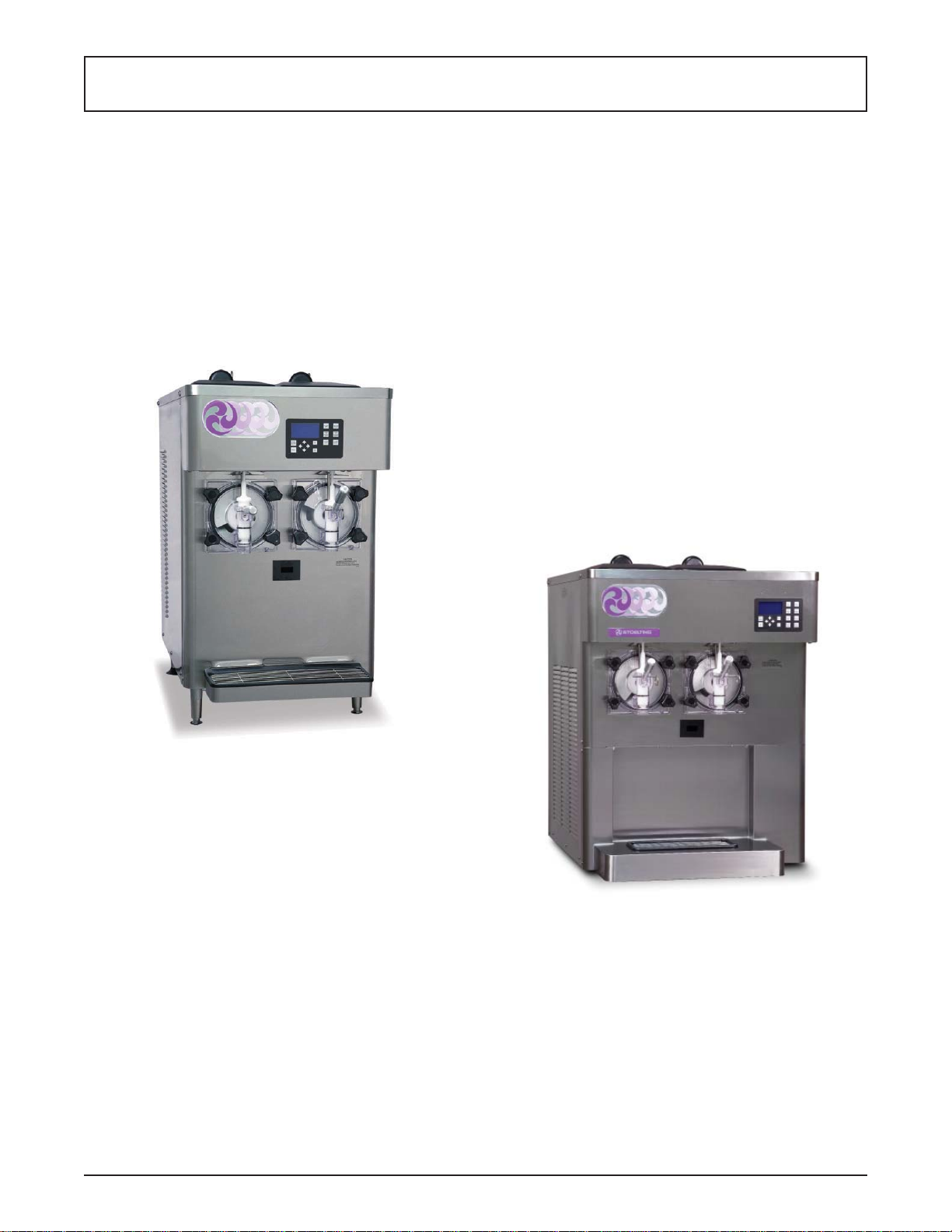
1.1 DESCRIPTION
The Stoelting E122 & F122 countertop machines are gravity fed. The machines are equipped with fully automatic
controls to provide a uniform product. This manual is
designed to help qualifi ed service personnel and opera-
tors with the installation, operation and maintenance of
the Stoelting E122 & F122 gravity machines.
Figure 1-1 Model E122
Figure 1-2 Model F122
Service Manual #513668 1 E122 & F122 Model Machines
Page 8
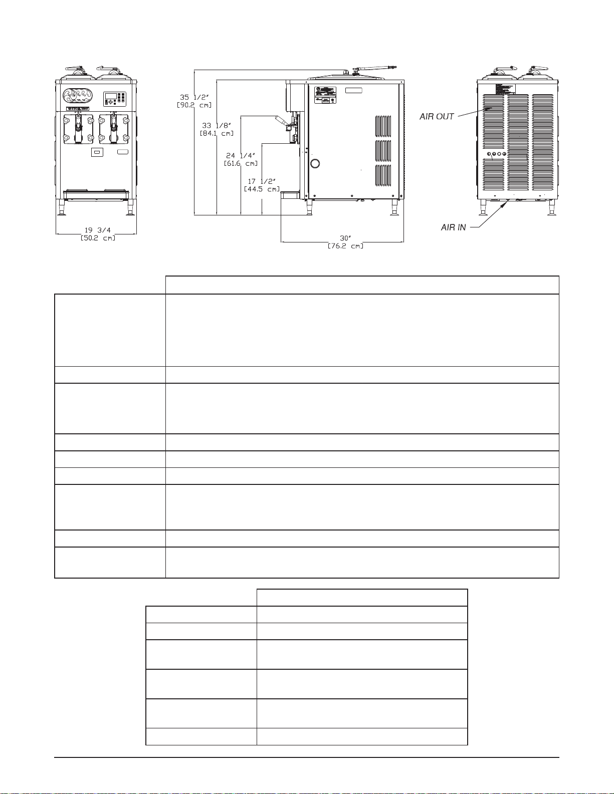
1.2 SPECIFICATIONS
Model E122
Dimensions Machine with crate
width 19-5/8’’ (49,8 cm) 28-1/2’’ (72,4 cm)
height 35-1/2’’ (90,2 cm) 44’’ (111,8 cm)
depth 30-1/4’’ (76,8 cm) 36’’ (91,4 cm)
Weight 275 lbs (124,7 kg) 278 lbs (126,0 kg)
Electrical 1 Phase, 208-240 VAC, 60Hz
running amps 10.6A
connection type NEMA6-15P power cord provided
Compressor 5,500 Btu/hr
Drive Motor Two - 1/3 hp
Air Flow Air cooled units require 4” (10,2 cm) air space in back
Water cooled units require 3/8” N.P.T. water and drain fi ttings. Maximum
Plumbing Fittings
water pressure of 130 psi. Minimum water fl ow rate of 3 GPM per barrel.
Ideal EWT of 50°-70°F.
Hopper Volume Two - 3 gallon (11,36 liters)
Freezing Cylinder
Volume
Two - 2.125 gallon (8,04 liters)
E122
Refrigerant R-404A
Charge 30 oz
Suction Pressure
(at 80-85°F)
23-26 psig
Discharge Pressure 270 psig
Hot Gas Bypass
Pressure
EPR Valve 68-70 psig
Service Manual #513668 2 E122 & F122 Model Machines
18 psig
Page 9
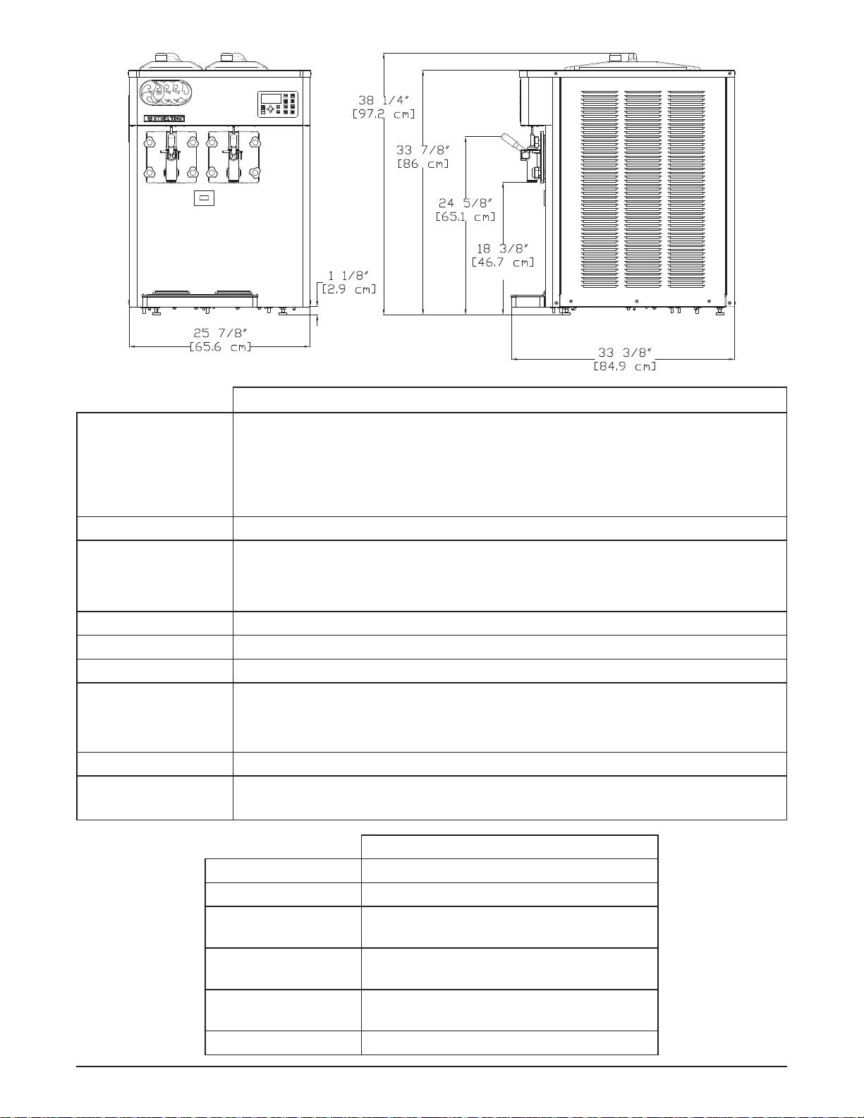
Model F122
Dimensions Machine with crate
width 25-7/8’’ (65,7 cm) 31-3/4’’ (80,6 cm)
height 38-1/4’’ (97,2 cm) 47-3/8’’ (120,3 cm)
depth 33-3/8’’ (84,8 cm) 41-1/4’’ (104,8 cm)
Weight 390 lbs (176,9 kg) 458 lbs (207,7 kg)
Electrical 1 Phase, 208-240 VAC, 60Hz
running amps 14.5A
connection type NEMA6-20P power cord provided
Compressor 12,000 Btu/hr
Drive Motor Two - 1/2 hp
Air Flow Air cooled units require 6” (15,24 cm) air space on both sides
Water cooled units require 3/8” N.P.T. water and drain fi ttings. Maximum
Plumbing Fittings
Hopper Volume Two - 3 gallon (11,36 liters)
Freezing Cylinder
Volume
water pressure of 130 psi. Minimum water fl ow rate of 3 GPM per barrel.
Ideal EWT of 50°-70°F.
Two - 2.125 gallon (8,04 liters)
F122
Refrigerant R-404A
Charge 40 oz
Suction Pressure
(at 72°F)
Discharge Pressure 225-235 psig
Hot Gas Bypass
Pressure
EPR Valve 68-70 psig
Service Manual #513668 3 E122 & F122 Model Machines
34 psig
14 psig
Page 10
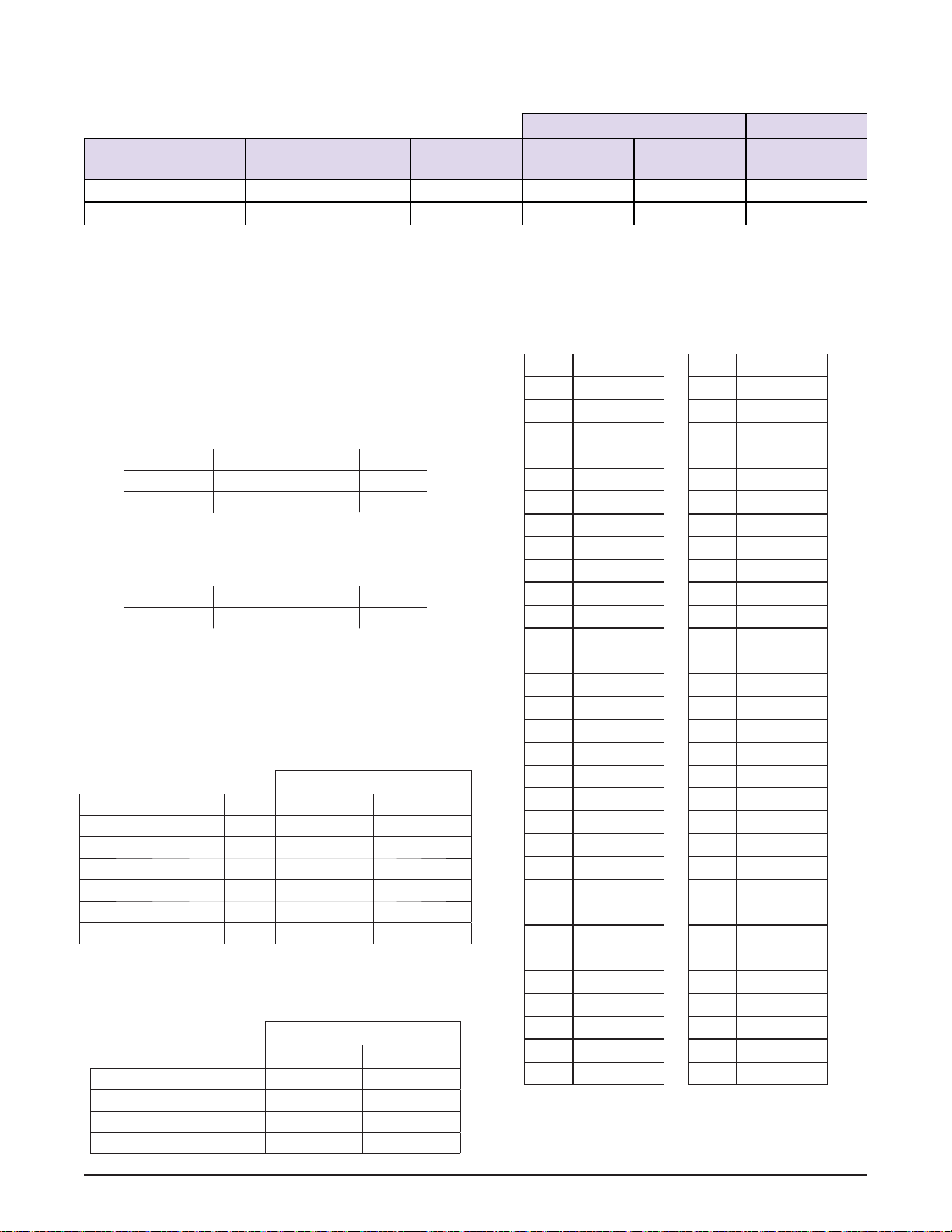
1.2 SPECIFICATIONS (CONTINUED)
PEAK HEAT OF REJECTION
Water Cooled Only Air Cooled Only
Model Electrical
Peak Heat of
Rejection
Peak Water
Usage
Estimated Wa-
ter Usage
AC Load Rating
E122 1 PH, 60Hz 11,511 BTU/hr 2.3 GPM 1.4 GPM 8,850 BTU/hr
F122 1 PH, 50Hz 14,947 BTU/hr 3.0 GPM 1.9 GPM 11,721 BTU/hr
1.3 COMPONENT SETTINGS
Following are the settings for the components in the
E122 & F122 machines.
C. TEMPERATURE CONTROL SENSOR
The following table shows the relationship between the
thermistor resistance and the suction line temperature.
A. COMPRESSOR WINDINGS
When testing the compressor windings the resistance
through the windings should be as follows:
F122
Compressor Electrical S to C R to C
282032-SV 1 PH 60Hz 3.10Ω 1.16Ω
282050 1 PH 50Hz 3.79Ω 1.39Ω
E122
Compressor Electrical S to C R to C
282094 1 PH 60Hz 5.94Ω 1.18Ω
B. CAPACITORS
Refer to the following table for the capacitance of all the
capacitors in the machine:
F122
Rating
Capacitor Part MFD VAC
Comp - Run (50/60 Hz) 231084 30 MFD 370 VAC
Comp - Start (60 Hz) 231079 145-174 MFD 220 VAC
Comp - Start (50 Hz) 230649 130-156 MFD 250 VAC
Drive Motor - Run 230687 30 MFD 370 VAC
Drive Motor - Start 230685 645-774 MFD 125 VAC
Fan Motor 230654 5 MFD 400 VAC
E122
Rating
Part MFD VAC
Compressor - Run 230666 20 MFD 440 VAC
Compressor - Start 230632 72-86 MFD 330 VAC
Drive Motor - Start 230447 189-227 MFD 165 VAC
Fan Motor 230665 88-106 MFD 330 VAC
°F Resistance °F Resistance
-22 176950 40 26100
-20 165200 42 24725
-18 154300 44 23400
-16 144200 46 22175
-14 134825 48 21000
-12 126125 50 19900
-10 118050 52 18875
-8 110550 54 17900
-6 103550 56 17000
-4 97075 58 16125
-2 91025 60 15325
0 85400 62 14550
2 80150 64 13825
4 75275 66 13150
6 70725 68 12500
8 66475 70 11875
10 62500 72 11300
12 58800 74 10750
14 55325 76 10250
16 52100 78 9750
18 49075 80 9300
20 46250 82 8850
22 43600 84 8450
24 41125 86 8050
26 38800 88 7675
28 36625 90 7325
30 34575 92 7000
32 32675 94 6675
34 30875 96 6375
36 29175 98 6100
38 27600 100 5825
Service Manual #513668 4 E122 & F122 Model Machines
Page 11
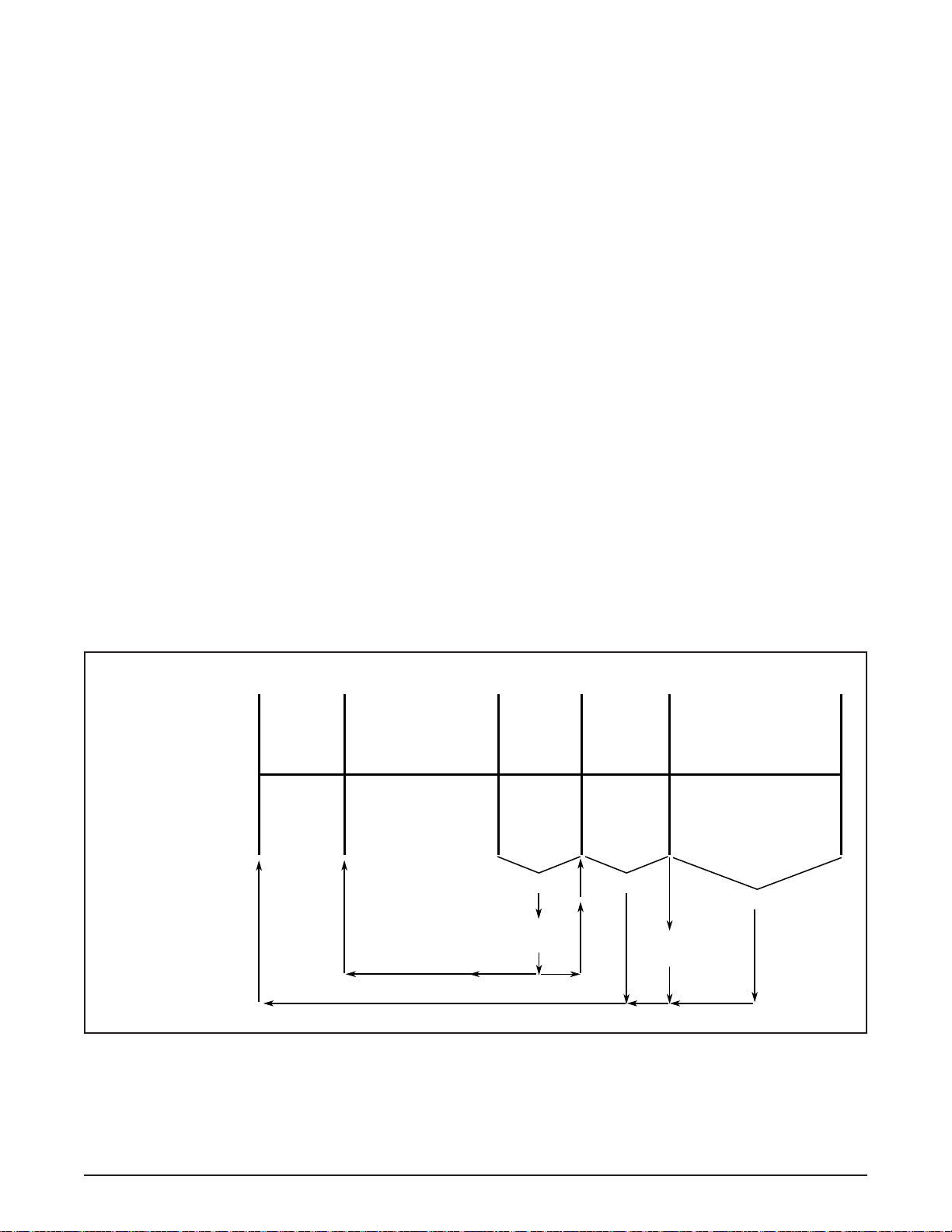
1.4 MODES OF NORMAL OPERATION
Following is an explanation of the normal operation modes
on the E122 and F122 (Refer to Figure 1-3).
NOTE
The machine uses the torque switch to maintain
product consistency. The IntelliTec2™ controls
the timers which include Pre Stir, Post Stir and Off
Time (standby).
A. PRE STIR
When the Push To Freeze button is pressed or when
the spigot is opened, the drive motor starts a 5-second
pre stir. The torque switch determines if a freezing cycle
begins. If the consistency of the product holds the torque
switch closed for 3 seconds the machine goes to Standby.
Otherwise a freezing cycle begins.
B. FREEZING CYCLE
The freezing cycle runs until the torque rod closes the
torque switch and keeps the switch closed for 3 seconds.
If product consistency is not met within 20 minutes, the
machine operates in the compressor time out mode (See
Section 1.5).
NOTE
If the spigot is pulled during a freezing cycle, the
20-minute timer restarts.
C. POST STIR
After the freezing cycle ends, the drive motor continues
to run for a 12 second post stir. The post stir ensures the
product does not freeze to the cylinder. If the spigot is
opened during the post stir, the machine checks consistency. If the product is at consistency, the machine goes to
standby. If the product is not at consistency, the machine
starts a freezing cycle.
D. STANDBY
The machine remains in Standby for 5 minutes or until
the spigot is pulled. At the end of Standby the machine
goes to Pre Stir if the cycle count has not been met. If the
cycle count has been met it goes to Refrigerate Mode.
E. REFRIGERATE MODE
After the cycle count is met without a spigot pull, the
machine is in Refrigerate Mode. It remains in refrigerate
mode until the spigot is pulled.
F. CLEAN MODE
When the Clean button is pressed, the drive motor starts
and runs for 20 minutes. After the 20 minutes expire, the
drive motor stops and a Clean alert will be displayed on
the IntelliTec2™. To clear the alert, press the On/Off button
for the cylinder to turn it off then press it again to turn it on.
CLEAN-OFF-ON
Switch Moved to ON
Pre Stir Post Stir
Drive
Motor
5
Seconds
Consistency
check.
Freezing Cycle
will not start if
the product is
at consistency.
Freezing Cycle
Drive Motor &
Cylinder Refrigeration
Until Consistency
Setting is Met
If this time exceeds 20
minutes, the Compressor
Time Out mode is initiated
Drive
Motor
12
Seconds
Spigot Pull
Product at
Consistency?
No Yes
Figure 1-3 Modes of Normal Operation
Standby
5
Minutes
Spigot Pull
cycle count is
Refrigerate
Drive Motor &
Cylinder Refrigeration
12 Minutes Off
5 Second Pre Stir
7 Second Refrigeration
5 Second Post Stir
Spigot Pull
To Pre Stir if
not met.
Service Manual #513668 5 E122 & F122 Model Machines
Page 12
Pre Stir Post Stir
Freezing Cycle
Standby
Drive
Motor
Drive Motor &
Cylinder Refrigeration
Compressor Run Time
Exceeds 20 Minutes
5
Seconds
Consistency
check.
Freezing Cycle
will not start if
the product is
at consistency.
Continues to operate until the cylinder is turned
off then on again using the On/Off button.
90 Seconds or
Until Consistency
Setting is Met
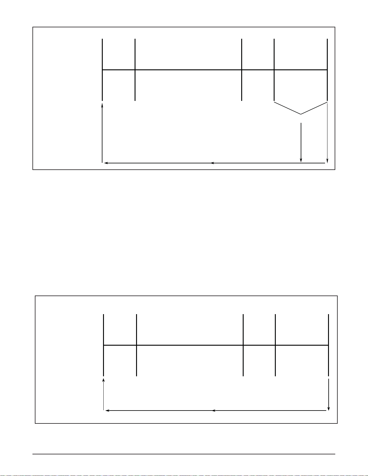
Figure 1-4 Compressor Time Out Mode
1.5 OPERATION DURING AN ERROR MODE
A. COMPRESSOR TIME OUT MODE
If the freezing cycle exceeds 20 minutes, the machine
operates on timers (Refer to Figure 1-4).
Drive
Motor
12
Seconds
7
Minutes
Spigot Pull
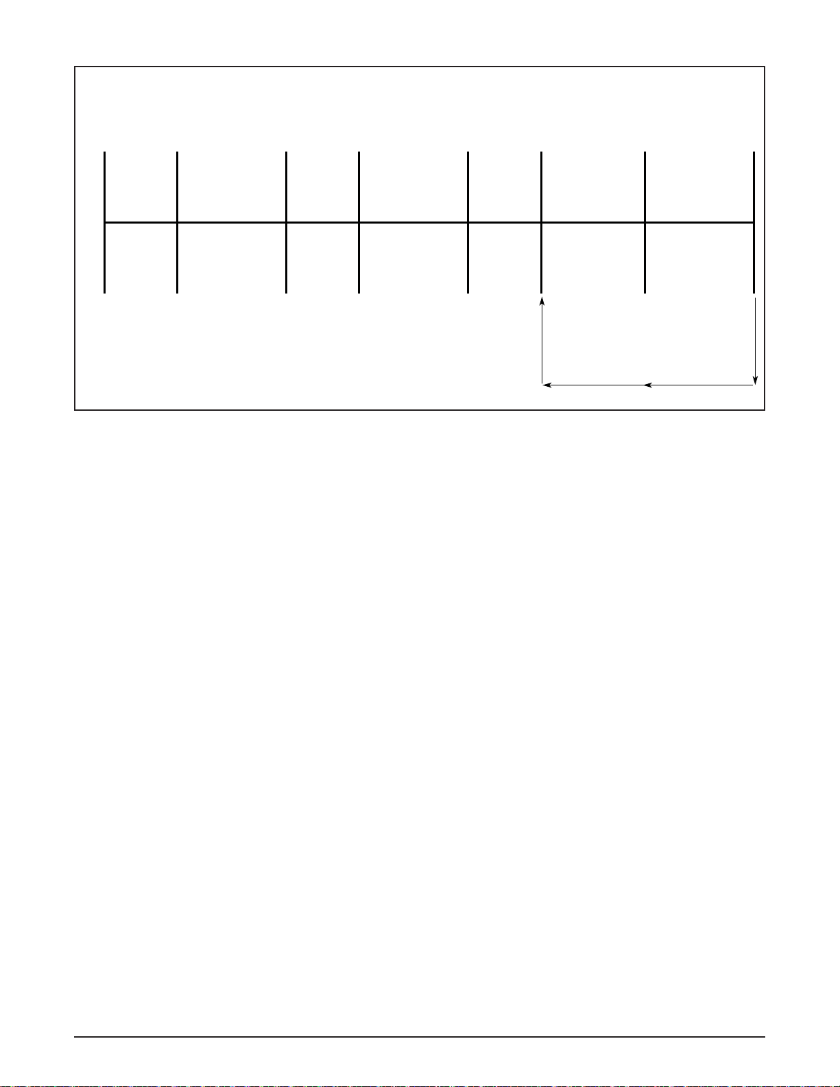
B. LOW MIX MODE
If the mix level falls below the sensor probe, the machine
operates on timers. The machine continues to operate
on timers until the mix level in the hopper is above the
sensor probe (Refer to Figure 1-5).
Pre Stir Post Stir
Drive
Motor
Freezing Cycle
Drive Motor &
Cylinder Refrigeration
Drive
Motor
Standby
Mix Level Falls
Below Sensor Probe
5
Seconds
10
Seconds
The freezer will return to normal operation
after mix level is above the sensor probe
12
Seconds
12
Minutes
Figure 1-5 Low Mix Mode
Service Manual #513668 6 E122 & F122 Model Machines
Page 13
First
Attempt
Pre Stir
Standby
Second
Attempt
Pre Stir
Standby
Third
Attempt
Pre Stir
Refrigeration
Cycle
Standby
Drive
Motor
5
Seconds
12
Minutes
Drive
Motor
5
Seconds
Minutes
Figure 1-6 Drive Motor Error Mode
C. DRIVE MOTOR ERROR MODE
If the control does not sense current from the drive motor
during a pre stir, the machine goes into standby mode for
12 minutes. After standby, the control repeats the pre stir
and attempts to sense drive motor current. After the third
pre stir without sensing drive motor current, the machine
operates on timers. If the spigot is pulled during standby,
the machine immediately attempts to sense drive motor
current.
12
Drive
Motor
5
Seconds
Cylinder
Refrigeration
7
Seconds
Continues to operate until the
cylinder is turned off then on again
using the On/Off button.
12
Minutes
Service Manual #513668 7 E122 & F122 Model Machines
Page 14

Service Manual #513668 8 E122 & F122 Model Machines
Page 15

SECTION 2
MAINTENANCE AND ADJUSTMENTS
This section is intended to provide maintenance personnel
with a general understanding of the machine adjustments.
It is recommended that any adjustments be made by a
qualifi ed person.
NOTE
There are many settings in the IntelliT ec2™ control
that do not affect the operation of the E122 or F122.
These settings will not be covered in this manual
and should not be changed.
2.1 ACCESSING CONTROL READINGS AND
SETTINGS
The readings and settings on the IntelliTec2™ control are
accessed by using a keypad sequence. Press the left arrow button from the Current Status screen to access the
passcode input screen.
The specifi c readings and parameters available depend
on the keypad sequence entered. The lowest level is Associate and has limited access. The Manager level has
access to the majority of screens except Utilities (2 of 2).
The Technician and Factory levels have full access to the
control including the Associate and Manager level options.
The Factory level has an additional factory settings menu.
Following are the keypad sequences for the three levels
available.
Associate Press the right arrow then the SEL button.
Manager Press the right arrow, up arrow then the
SEL button
Technician Press the right arrow, SET, then the SEL
button
Factory Press the right arrow, down arrow, SET,
up arrow then the SEL button.
2.2 NAVIGATION AND MODIFYING SETTINGS
Navigating through the IntelliTec2™ screens is done with
the arrow keys on the touchpad. After positioning the cursor on a desired menu, press the SEL button to select
that option. To change a setting, press the SET button.
Use the arrow keys to change the value. Press the SET
button to save the changes.
The SEL button changes the cylinder selection on screens
that show the cylinder.
Pressing the left arrow button from any menu will go back
one screen. Pressing the left arrow button at the Main
Menu screen goes to the Current Status screen.
2.3 USER INTERFACE SCREENS
A. CURRENT STATUS
Current Status 01/01/01
12:34:56
Left Off
Right Off
Storage Hoppers Off
Left Hopper Autofill On
Right Hopper Autofill On
_ Service Company
The Current Status screen gives an overview of the
machine's operation. It shows the mode of the freezing
cylinders, the storage refrigeration, and the status of the
autofi ll system. If there is an error, the error text descrip-
tion replaces the status information.
The Service Contact Information screen is accessed from
the Current Status screen. Move the cursor to the Service
Contact Information option and press the SEL button.
B. SERVICE CONTACT INFORMATION
Service Contact Information
Name
Stoelting
Telephone Number
800 - 319 - 9549
Unit Serial Number
1234567AA
Version 00.00/00.00
The Service Contact Information screen provides the
name and telephone number for service. The default is
Stoelting White Glove Service. The default can be changed
by selecting the Modify Contact Information option or by
uploading the info.txt fi le.
C. MAIN MENU
Main Menu
- Technician Level Access
_ Fine Consistency Adjustment
_ Performance
_ Modify Settings
_ Utilities
_ Errors and Statistics
The Main Menu screen provides access to all the readings and settings on the IntelliTec2™ control. To access
the Main Menu, use one of the keypad sequences from
Section 2.1. The example above shows the options available when entering the Manager, Technician or Factory
keypad sequence. The Associate will only see the Fine
Consistency Adjustment option.
Service Manual #513668 9 E122 & F122 Model Machines
Page 16

D. FINE CONSISTENCY ADJUSTMENT
The Fine Consistency Adjustment screen has no effect
on machine operation.
2.5 SETTINGS SCREENS
A. MODIFY OPERATING SETTINGS
2.4 PERFORMANCE SCREENS
A. PERFORMANCE (1 OF 2)
Performance (1 of 2)
Cylinder Right
Consistency 000.00
Cylinder Temp -000.0°F
Motor Amps 00.000A
Input Voltage 000.0V
The Performance screens display the current status of the
machine. These screens are available to the Manager,
Technician, and Factory levels. Press the right arrow to
go to the second screen.
Cylinder
The performance information displayed is for the selected
cylinder. To change cylinders press the SEL button.
Consistency
Disregard this value. Product consistency is regulated by
the torque switch (See Section 2.8)
Cylinder Temperature
This is the current suction line temperature of the selected
cylinder.
Motor Amps *
This is the motor amps of the selected cylinder. Note
that the Motor Amps are not used to determine product
consistency.
Input Voltage *
This is the voltage of the selected cylinder.
* Only shown when the drive motor is running.
B. PERFORMANCE (2 OF 2)
Performance (2 of 2)
Cylinder Right
Ambient Temp -000.0°F
Storage Temp -000.0°F
Number of Cycles 000
Modify Operating Settings
Reset Serve Amount
_ Basic Settings
_ Advanced Settings
_ Storage Settings
_ User Preferences
_ Time and Date
_ Factory Settings
This menu provides access to view and change the different
operating settings on the machine. The Manager, Technician, and Factory levels have access to these screens.
B. BASIC SETTINGS
Basic Settings
Cylinder Right
_ CutOut Consist Offset 000
_ CutIn Consist Offset 000
_ Cycles In Serve Mode 000
_ CutIn Refrig Temp 00.0°F
_ CutOut Refrig Temp 00.0°F
This menu contains settings for the CutIn and CutOut,
cycles in serve mode and auger cycle times. This screen
is available to the Technician and Factory levels.
Cylinder can be changed by pressing the SEL button.
CutOut Consistency Offset has no effect on machine
operation.
CutIn Consistency Offset has no effect on machine
operation.
Cycles In Serve Mode is a count of the number of freez-
ing cycles.
CutIn Refrig T emp is the suction line temperature in the
cylinder when a freezing cycle will start during Refrigerate
Mode. Decreasing this value lowers product temperature.
CutOut Refrig T emp is the suction line temperature in the
cylinder when a freezing cycle will stop during Refrigerate
Mode. Decreasing this value lowers product temperature.
Error Status No Error
The Performance screens display the current status of
the machine. This screen shows the current ambient temperature, storage temperature, and number of cycles since
the Push to Freeze button was pressed or the spigot was
pulled. Press the left arrow to go back to the fi rst screen.
Service Manual #513668 10 E122 & F122 Model Machines
Page 17

C. ADV ANCED SETTINGS
The Advanced Settings options have no effect on machine
operation.
E. STORAGE SETTINGS (1 OF 2)
Storage Settings (1 of 2)
_ Storage Refirgeration Active
_ Storage CutIn -00.0°F
_ Storage CutOut -00.0°F
_ Storage Degree Offset 00°F
_ Storage Off Time 00 min
_ Storage On Time 0000 sec
The Temperature Units setting changes the units dis-
played to Fahrenheit or Celsius.
The Service Contact Information option is used to change
the service contact details including service company
name and number and machine serial number.
The Contact Information USB Update option is used for
uploading the info.txt fi le. The info.txt fi le is available from
Stoelting White Glove Service and contains the service
company name and telephone number. Select this option
after connecting a USB drive to the port on the machine.
H. TIME AND DATE
Time and Date
This Storage Settings menu contains storage refrigeration
parameters and is available to the Technician and Factory
level. Press the right arrow to go to the second screen.
Storage Refrigeration can be set to Active or Suspend.
Active is the normal setting. Suspend is used only for
troubleshooting and setting an expansion valve. Never set
storage refrigeration to Suspend during normal operation.
Storage CutIn has no effect on machine operation.
Storage CutOut has no effect on machine operation.
The Storage Degree Offset value is added to the storage
temperature reading to determine if storage refrigeration
starts with a freezing cycle. This setting is used in conjunction with the Storage Off Time and Storage On Time
during an error.
The Storage Off Time setting determines the time be-
tween storage refrigeration cycles during a sensor failure.
The Storage On T ime setting determines the length of a
storage refrigeration cycle during a sensor failure.
F. STORAGE SETTINGS (2 OF 2)
This Storage Settings options have no effect on machine
operation.
G. USER PREFERENCES
User Preferences
_ Language English
_ Temp Units Farenheit(°F)
_ Service Contact Information
_ Contact Information USB Update
The User Preferences menu contains language options,
temperature units, and service contact information. The
screen is available to the Manager, Technician, and Factory levels.
The Language setting changes the language displayed.
English is the only language currently available.
Time 00:00:00 AM
Date 00/00/00
Daylight Savings Off
Clock Type 12 HR
Date Format
_ Modify Time and Date
The Time and Date menu shows the time and date settings. The Manager, Technician, and Factory levels can
change the time and date by using the Modify Time and
Date option.
I. FACTORY SETTINGS (1 OF 6)
Factory Settings (1 of 6)
Cylinder Right
_ Pre Stir 00 sec
_ Post Stir 00 sec
_ Off Time 0000 sec
_ Consistency Sensing Switch
The Factory Settings screen 1 of 6 contains timer settings.
The screen is available only to the Factory level.
The Pre Stir setting is the amount of time the machine
will perform a consistency check before a freezing cycle
begins. During the pre stir the drive motor will run and
the machine will monitor the torque switch.
The Post Stir setting is the amount of time the drive mo-
tor will operate after a freezing cycle ends. The post stir
ensures product does not freeze to the cylinder.
The Off Time setting is the standby time. It is the period
between the end of the Post Stir and start of the Pre Stir
(without opening the spigot).
Consistency Sensing has no effect on machine operation.
J. FACTORY SETTINGS (2 OF 6) THROUGH (6 OF 6)
The remaining factory settings screens do not affect machine operation and should not be changed.
Service Manual #513668 11 E122 & F122 Model Machines
Page 18

2.6 UTILITIES SCREENS
B. TOUCHPAD LOCKUP
Utilities (1 of 2)
_ Adjust LCD Contrast
_ Touchpad Lockup
_ Export Machine Stats
_ Clean Options
Next Utilities Menu
Utilities (2 of 2)
_ Testing and Manual Operation
_ Unit Calibration
_ Clear Log Data
_ Restore Factory Defaults
_ Reset Unit Configuration
The Utilities menu gives access to various settings and
operations in the control. The Utilities menu is available to
the Manager, Technician, and Factory levels. The Manager
level will only have access to the fi rst screen. The Tech-
nician and Factory levels have access to both screens.
NOTE
Entering the Utilities (2 of 2) screen automatically
shuts off the freezing cylinders (refrigeration and
drive motors).
A. ADJUST LCD CONTRAST
Touchpad Lockup
Touchpad Status: Unlocked
Do you want to lock keys
_ No Unlock Touchpad
_ Yes Lock Touchpad
The Touchpad Lockup is used to lock and unlock the
keypad for self service locations.
C. EXPORT MACHINE STATS
Export Machine Stats
This will export statistics
data to stats.txt file
Please insert USB flash memory
Are you sure you want to do that
_ No
_ Yes
The Export Machine Stats screen allows you to export
all the data and statistics stored in the control. Connect a
USB fl ash drive (1 MB minimum) to the port on the side
of the machine and select the yes option.
D. CLEAN OPTIONS
Clean Options
Adjust LCD Contrast
0123456789
ABCDEFGHIJKLMNOPQRSTUVWXYZ
ź to change
Press
Ÿ
The Adjust LCD Contrast screen adjusts the contrast between the background lighting and the text on the screen.
Clean History Log
Clean Warning
Clean Lockout
The Clean Options Menu gives access to the Clean History Log and Clean Lockout options.
The Clean History Log screen shows the date, time and
duration of the last 32 clean cycles.
Clean History Log (32 of 32)
Cylinder Right
Clean Log ID 0: 00/00/00
00:00:00
Clean Total Time 000 min
Service Manual #513668 12 E122 & F122 Model Machines
Page 19

The Clean Warning and Clean Lockout screens are
used to enable the clean warning mode or the clean
lockout mode. When one of the modes is enabled and
the machine is not cleaned within a specifi ed period, the
machine will either display a warning (for warning mode)
or remain in sleep mode and not go into serve mode (for
lockout mode).
Clean Warning
Clean Warning Enabled
This option will
require cylinder cleaning
Are you sure you want to do that
_ No - Cancel Clean Warning
_ Yes - Enable Clean Warning
Clean Lockout
Clean Lockout Disabled
This option will
enforce cylinder cleaning
Are you sure you want to do that
_ No - Cancel Clean Lockout
_ Yes - Enable Clean Lockout
F. TESTING AND MANUAL OPERATION
The Testing and Manual Operation menu provides access
for individual components to be energized to assist with
troubleshooting. There are also test monitoring screens
that provide details of the machine status during testing.
Any energized component will deenergize after leaving
the Testing and Manual Operations menu.
Testing and Manual Operation
Select below for testing
_ Left Output Control
_ Right Output Control
_ Left / Right Monitoring
Selecting Left or Right Output Control goes to a screen
that allows motors, solenoids, or the compressor to be
individually activated. Activate by moving the cursor to the
desired component and pressing the SET button.
Testing and Manual Ops, Left
_ Drive Motor Off
_ Fan Motor Off
_ Liquid Solenoid Off
_ Compressor Off
_ Refer Solenoid Off
_ Aux Solenoid Off
_ Pump Motor Off
Selecting Left/Right Monitoring goes to screens that show
current statistics of the selected cylinder.
The Test Monitoring screens can be used for immediate
feedback when troubleshooting. For example the spigot
switch can be tested by opening the spigot and observing
if the status text changes from "Closed" to "Open".
Test Monitoring (1 of 3)
Cylinder Right
CRC Errors Dis/IO 0/6791
Motor Voltage 0.0 V
Motor Current 0.000
I/V Phase Angle 0.0°
Frequency 0.0 Hz
Consistency 0.0
Test Monitoring (2 of 3)
Cylinder Right
CRC Errors Dis/IO 0/12
Ambient Temp +00.0°F
Cylinder Temp +00.0°F
Storage Temp +00.0°F
Liquid Level OK
Test Monitoring (3 of 3)
Cylinder Right
CRC Errors Dis/IO 0/12
Spigot Closed
Door Closed
Hi Pressure No
Torque Switch Input Off
Service Manual #513668 13 E122 & F122 Model Machines
Page 20

G. UNIT CALIBRATION
The Unit Calibration screens have no effect on machine
operation.
H. MOTOR CALIBRATION
The Motor Calibration screen has no effect on machine
operation.
H. CLEAR LOG DATA
Clear Log Data
This will clear the error log
and the statistics.
Are you sure
you want to do that
_ No
_ Yes
The Clear Log Data screen will clear all the errors and
statistics in memory.
I. RESTORE FACTORY DEFAULTS
Restore Factory Defaults
2.7 ERRORS & STATISTICS SCREENS
The Errors & Statistics menu gives the Technician and Factory levels access to machine statistics and error history.
Errors and Statistics
_ Machine Statistics
_ Error History
A. MACHINE STATISTICS (1 OF 10)
Machine Statistics (1 of 10)
Cylinder Right
Time in Serve Mode 0000 hr
Last 24hrs 0000 min
Last 7days 0000 hr
Time in Off Mode 0000 hr
Last 24hrs 0000 min
Last 7days 0000 hr
This will reset all machine
settins to the original
factory configurations. Are
you sure you want to do that
_ No
_ Yes
The Restore Factory Defaults screen is used to restore
the control to the original factory confi guration.
J. RESTORE UNIT CONFIGURATION
Reset Unit Configuration
This will reset the unit type
and motor types.
Are you sure you want to do that
_ No
_ Yes
The Restore Unit Confi guration screen allows you to
change the motor type default. The E122 unit confi gura-
tion is 0, and the F122 unit confi guration is 1.
The Machine Statistics screen 1 of 10 shows the time in
serve mode and time in sleep mode. The screen shows a
running total, the total for the previous day, and the total
for the previous week for both statistics.
B. MACHINE STATISTICS (2 OF 10)
Machine Statistics (2 of 10)
Cylinder Right
Total Low Mix Time 0000 hr
Last 24hrs 0000 min
Last 7days 0000 hr
The Machine Statistics screen 2 of 10 shows the low mix
running time. This is the total time, including serve mode
and sleep mode, that the freezing cylinder was operating
with a low mix error. The screen shows a running total,
the total for the previous day, and the total for the previous week.
Service Manual #513668 14 E122 & F122 Model Machines
Page 21

C. MACHINE STATISTICS (3 OF 10)
F. MACHINE STATISTICS (6 OF 10)
Machine Statistics (3 of 10)
Cylinder Right
Last Clean Cycle 00/00/00
00:00:00 AM
Last Clean Time 0000 min
The Machine Statistics screen 3 of 10 provides the time
and date that the freezing cylinder was last cleaned. This
value is recorded when the Clean button is pressed on
the touchpad. The screen also shows how long the most
recent clean mode lasted.
D. MACHINE STATISTICS (4 OF 10)
Machine Statistics (4 of 10)
Cylinder Right
Spigot Open Total 0000 min
Last 24hrs 0000 min
Last 7days 0000 min
Spigot Total Cycles 0000
Average Spigot Open 0000 sec
Machine Statistics (6 of 10)
Cylinder Right
Compressor Run Time 0000 hr
Compressor Cycles 0000
Last Compressor Reset 00/00/00
00:00:00
_ Reset Compressor Time
The Machine Statistics screen 6 of 10 shows the total run
time for the compressor and counts the total cycles. There
is an option to reset the timer and the screen shows when
the last reset was done. Only reset the compressor time
if the compressor is changed.
G. MACHINE STATISTICS (7 OF 10)
Machine Statistics (7 of 10)
Cylinder Right
Motor Run Time 0000 hr
Motor Cycles 0000
Last Motor Reset 00/00/00
00:00:00 AM
_ Reset Motor Time
The Machine Statistics screen 4 of 10 shows the total time
that the spigot has been open during serve mode. The
screen shows a running total, the total for the previous
day, and the total for the previous week. The screen also
shows the total times that the spigot has been opened.
E. MACHINE STATISTICS (5 OF 10)
Machine Statistics (5 of 10)
Cylinder Right
Estimated Serve Amount 0000 gal
Last Reset Amount
00/00/00
00:00:00 AM
The Machine Statistics screen 5 of 10 gives the estimated
serve amount of the freezing cylinder based on the time
the spigot is open during serve mode. The estimation is
also calculated for the previous day and the previous week.
The screen gives an option to reset the serve amount and
shows when the last reset was done.
The Machine Statistics screen 7 of 10 shows the total run
time for the drive motor and counts the total cycles. There
is an option to reset the timer and the screen shows when
the last reset was done. Only reset the motor time if the
drive motor is changed.
H. MACHINE STATISTICS (8 OF 10)
Machine Statistics (8 of 10)
Cylinder Right
Pump Run Time 0000 hr
Pump Cycles 0000
Last Pump Reset 00/00/00
00:00:00 AM
_ Reset Pump Time
The Machine Statistics screen 8 of 10 does not apply to
this machine.
Service Manual #513668 15 E122 & F122 Model Machines
Page 22

I. MACHINE STATISTICS (9 OF 10)
L. STATUS AT TIME OF ERROR
Machine Statistics (9 of 10)
Cylinder Right
Current Hose Usage 0000 hr
Hose Service Limit 100 hr
Last Hose Reposition 00/00/00
00:00:00 AM
_ Reset Hose Service Time
The Machine Statistics screen 9 of 10 does not apply to
this machine.
J. MACHINE STATISTICS (10 OF 10)
Machine Statistics (10 of 10)
Last Unit Power Up 00/00/00
00:00:00
Avg Power KWH/Day 0 Watts
Status at Time of Error
Operating Mode Off
Mix Levels Full Level
Consistency 000.00
Input V/A/P 000.0V 00 00
Outputs Status 0 0 0 0 0 0 0
Inputs Status 0 0 0 0 0 0
Amb/Cyl Temp -000.0°F -000.0°F
The Status at Time of Error screen gives data for the time
the error occurred.
The Machine Statistics screen 10 of 10 shows when the
machine was last powered on. The screen also gives an
average power consumption per day.
K. ERROR HISTORY
Error History 25 of 25
Type Cylinder Sensor
Date 00/00/00 00:00:00 AM
Cylinder Right
_ Status At Time of Error
_ Help
The Error History screen shows the last error that occurred.
The screen shows the type of error, the time and date and
the cylinder that had the error. Up to 25 errors are stored.
Press the up or down arrow to scroll through the errors.
Select the Status at Time of Error option to view data for
the time the error occurred. The Help option explains the
error and provides quick troubleshooting tips.
Service Manual #513668 16 E122 & F122 Model Machines
Page 23

2.8 PRODUCT CONSISTENCY ADJUSTMENT
The Consistency Adjustment Screw increases or decreases product consistency by changing the amount of
torque needed to complete a refrigeration cycle. Turn the
knob clockwise to increase consistency.
Consistency Adjustment ScrewConsistency Adjustment Screw
TENSION SPRINGS
An optional spring is included with the machine and is
for use with shake mixes only. It is located behind the
header panel. To change springs, remove the header
panel, unhook the original spring from the torque switch
assembly and hook the new spring into place.
E122 - The standard spring is green. The optional
spring is yellow. The yellow spring is thicker.
F122 - The standard spring is yellow. The optional
spring is red. The red spring is thicker.
2.9 DRIVE BELT TENSION ADJUSTMENT
To check belt tension, follow the steps below:
A. Remove the side panels and back panel.
B. Use a Burroughs Belt Tension Gauge to check
the drive belt tension. The belt tension should be
50-55 lbs.
C. If an adjustment is necessary, loosen the four
motor plate retaining nuts, adjust belt tension
bolt then retighten the four nuts.
D. Using a straightedge, check that the drive motor
pulley is aligned with the speed reducer pulley.
Align the pulley if necessary.
NOTE
Belt life will be increased if new drive belts are
tightened after two or three weeks of operation.
2.10 PREVENTIVE MAINTENANCE
Stoelting recommends that a maintenance schedule be
followed to keep the machine clean and operating properly.
A. DAILY
1. The exterior should be kept clean at all times to
preserve the luster of the stainless steel. A mild
alkaline cleaner is recommended. Use a soft cloth
or sponge to apply the cleaner.
2. Make sure nothing is blocking airfl ow around the
machine.
B. WEEKLY
1. Check o-rings and rear seal for excessive wear
and replace if necessary.
2. Remove the drip tray by gently lifting up to
disengage from the support and pulling out. Clean
behind the drip tray and front of the machine.
C. QUARTERLY
The air-cooled condenser is a copper tube and aluminum
fi n type. Condensing is totally dependent upon airfl ow.
A plugged condenser fi lter, condenser, or restrictions in
the louvered panel will restrict airfl ow. This will lower the
capacity of the system and damage the compressor.
The condenser must be kept clean of dirt and grease. The
E122 must have a minimum of 4" (10.2 cm) of ventilation at
the back. The F122 must have a minimum of 6” (15.2 cm)
of ventilation on both sides of the unit for free fl ow of air.
The condenser and condenser fi lter require periodic clean-
ing. To clean, refer to the following procedures.
F122 Air Cooled Condenser Cleaning
A. Disconnect power to the machine
B. Remove the Phillips head screws from the right
side panel, and remove the panel.
C. To remove a condenser fi lter, grasp the top and
pull off. Visually inspect the fi lters for dirt. If a
fi lter is dirty, shake or brush excess dirt off the
fi lter and wash it in warm, soapy water. Once it
is clean, rinse it thoroughly in warm, clear water
and shake dry, taking care not to damage the
fi lter in any way.
E122 Air Cooled Condenser Cleaning
A. Unscrew the knob located on the underside of
the machine.
B. Remove the fi lter bracket and remove the fi lter.
C. Visually inspect the condenser fi lter for dirt.
D. If the fi lter is dirty, vacuum or brush clean, rinse
with clean water and allow to dry before replacing
on the machine.
Service Manual #513668 17 E122 & F122 Model Machines
Page 24

D. SEMI-ANNUALLY
1. Disconnect the machine from the power source.
2. Check drive belt for proper tension.
3. Lubricate condenser fan motor with S.A.E. 20
weight oil. Three to six drops is required.
4. Sanitize the autofi ll system (if applicable) following
the steps below:
AUTOFILL SANITIZING
A. If necessary, disassemble, clean and sanitize the
machine.
NOTE
If the machine does not require cleaning and sanitizing, press the Pump On/Off button to turn off the
pump. Then dispense enough product so that the
mix level in the hopper is below the long probe. If
the mix level is above the long probe, the solenoid
will not activate and the pump will not operate.
B. Prepare Stera-Sheen Green Label Sanitizer
or equivalent according to manufacturer’s
instructions to provide a 100ppm strength solution.
Mix the sanitizer in quantities of no less than 2
gallons of 90° to 110°F (32° to 43°C) water. Any
sanitizer must be used only in accordance with
the manufacturer’s instructions.
C. Cut an adapter from an empty bag of syrup.
Connect the adapter to the Bag-In-Box (BIB)
connector of the syrup line. Put the BIB connector
into the bucket of sanitizer.
NOTE
If you do not have an empty bag of syrup, remove
the plug from the top of the BIB connector. Do not
lose the plug; it is needed for proper operation of
the BIB.
H. The pump is now ready to operate. Place the
hopper cover on the hopper.
2.11 EXTENDED STORAGE
Refer to the following steps for storage of the machine
over any long period of shutdown time:
A. Follow the cleaning and sanitizing procedures
for the machine and follow the semi-annual
instructions to sanitize the autofi ll system.
B. Press the Main Power On/Off button so that power
to the machine is off.
C. Disconnect (unplug) from the electrical supply
source.
D. Thoroughly clean all parts that come in contact
with mix. Rinse in clean water and dry parts. Do
not sanitize.
NOTE
Do not leave cleaning solution in the hopper or in
the freezing cylinder during the shutdown period.
E. Remove, disassemble and clean the front door,
mix inlet regulator and auger parts.
D. Make sure the display screen shows that the
main power is on. Hold the hopper cover over a
bucket and press the Pump On/Off button. The
solenoid will activate and the brix pump will pump
sanitizer into the bucket.
NOTE
The solenoid will only activate when there is not any
liquid touching the longer mix probe in the hopper.
E. After all the sanitizer has run through the pump,
press the Pump On/Off button to turn off the pump.
F. Disconnect the bag adapter from the BIB connector
(or reinsert the plug into the connector). Connect
the BIB connector to the syrup BIB.
G. Hold the hopper cover over a bucket and press the
Pump On/Off button. This will fl ush the sanitizer
out of the pump and tubing. Once the sanitizer
is fl ushed out, press the Pump On/Off button.
Service Manual #513668 18 E122 & F122 Model Machines
Page 25

SECTION 3
!"#!
#
$%&
+&*
),/4.5
)*
0
#
$'
0
2#
0
2#
0#
#
0#
#
$
'
!"#!
#
$%&'
(#
)*
!
#
$
'
!"#!
#
$%&'
(#
)*
!
#
$%&
+&*
REFRIGERATION & WIRING DIAGRAMS
Service Manual #513668 19 E122 & F122 Model Machines
Page 26

E122-38I2AF
Service Manual #513668 20 E122 & F122 Model Machines
Page 27

E122-38I2AF
Service Manual #513668 21 E122 & F122 Model Machines
Page 28

E122-38I2 & E122-38I2P
Service Manual #513668 22 E122 & F122 Model Machines
Page 29

E122-38I2 & E122-38I2P
Service Manual #513668 23 E122 & F122 Model Machines
Page 30

F122-38I2-AF & F122-38I2AF
Service Manual #513668 24 E122 & F122 Model Machines
Page 31

F122-38I2 & F122-38I2P
Service Manual #513668 25 E122 & F122 Model Machines
Page 32

F122X-302I2
Service Manual #513668 26 E122 & F122 Model Machines
Page 33

F122-38I2 & F122-38I2P
Service Manual #513668 27 E122 & F122 Model Machines
Page 34

Service Manual #513668 28 E122 & F122 Model Machines
Page 35

SECTION 4
REPLACEMENT PARTS
4.1 DECALS AND LUBRICATION
Quantity
Part Description E122 F122
C-1000-26C Decal - Made In USA 1 1
208135 Brush - 4” X 8” X 16” (Barrel) 1 1
208380 Brush - 1/4” X 3” X 14” 1 1
208401 Brush - 1” X 3” X 10” 1 1
232091 Cap - Protective (Gray) - #490716 Leg 1
236054 Card - Cleaning Instructions - Brix Pump (Auto Fill) 1 1
236065 Card - Cleaning Instruction - E122 & F122 1 1
324065 Decal - Water Inlet 1
324105 Decal - Caution Electrical Shock 4 3
324106 Decal - Caution Electrical Wiring Materials 1 1
324107 Decal - Caution Hazardous Moving Parts 2 2
324141 Decal - Caution Rotating Blades 1 1
324208 Decal - Attention Refrigerant Leak Check 2 2
324509 Decal - Cleaning Instructions 1 1
324548 Decal - Adequate Ventilation 6” 2 2
324594 Decal - Attention Heat Sensitive 2 2
324686 Decal - Danger Automatic Start 2
324804 Decal - Domed Stoelting Swirl (Header Panel) 1 1
324888 Decal - Fan Motor Reset 1
324901 Decal - Transformer Switch 1
324909 Decal - USB Port 1 1
324921 Decal - Arctic Quake 1
324922 Decal - Assembly Check 1
324938 Decal - 4” Ventilation 1
325023 Decal - Stoelting (Black) (Large) 1 1
325024 Decal - Stoelting (Black) (Small) 1 1
325032 Decal - White Glove Service 1 1
396245 Gasket - Freezer Base 1
490716 Leg 4
490749 Leg - Front 2
490750 Leg - Rear (w/Suction Cup) 2
508053 Lubricant - Total Blend (50 Packets) 1 1
513667 Manual - Operators 1 1
1183955 O-Ring Kit -
2183636 Spacer - Leg 4
2203790 Sensor Probe Kit - -
Service Manual #513668 29 E122 & F122 Model Machines
Page 36

4.2 AUGER SHAFT AND FACEPLATE PARTS
630053
630053
336551
336551
2183447
2183447
2183099
2183099
570197
570197
482019
482019
624645
2203370
2203370
624644
624644
624645
2202068
2202068
2202181
2202181
2183444
2183444
2183751
2183751
2204226
2204226
666786
666786
624678
624678
2203224
2203224
2203555
624515
624515
624545
624545
2183449
2183449
Quantity
Part Description E122 F122
336551 Door - Front 2 2
482019 Knob - Front Door (Black) 8 8
570197 Pin - Cotterless Clevis (Front Door) 2 2
624515-5 O-Ring - Stator Bar Rear (5 Pack) 2 2
624545-5 O-Ring - Stator Bar Front (5 Pack) 2 2
624644-5 O-Ring - Spigot Body (Bottom) (5 Pack) 2 2
624645-5 O-Ring - Spigot Body (Top) (5 Pack) 2 2
624678-5 O-Ring - Rear Seal - Black (5 Pack) 2 2
625310 Quad-Ring - Front Door - Black 2 2
630053 Rod - Torque Actuator 2 2
666786 Seal - Rear Auger - Black 2 2
2183099 Breaker Bar - Spigot Body 2 2
2183444 Bushing - Stator Support (Rear) 2 2
2183447 Handle Only - Spigot 2 2
2183449 Bushing - Front Auger Support 2 2
2183751 Blade - Scraper 2
2202068 Stator Bar 2
2202181 Stator Bar 2
2203224 Auger Shaft 2
2203370 Spigot Body 2 2
2203555 Auger Shaft 2
2204226 Blade - Scraper 2
625310
625310
2203555
Service Manual #513668 30 E122 & F122 Model Machines
Page 37

4.3 HOPPER PARTS
2187918
2187918
2187919
2187919
314453
314453
2203078
2203078
744252
744252
744281
744281
2187058
2187058
2203090
2203090
2203206
2203206
624607
624607
417006
417006
417031
417031
744273
744273
744609
744609
Quantity
Part Description E122 F122
314453 Cover - Hopper 2 2
417006 Grid - Drip Tray (Vinyl Coated Metal) 1
417031 Grid - Drip Tray 1
624607-5 O-Ring - Mix Inlet (5 Pack) 4 4
744252 Tray - Drain 1
744273 Tray - Drip 1
744281 Tray - Drain (Front) 1
744609 Tray - Drip 1
2187058 Mix Inlet Regulator 2
2187918 Mix Inlet Adapter (Auto Fill) 2 2
2187919 Clip - Retaining (Mix Inlet Adapter) (Auto Fill) 2 2
2203090 Mix Inlet Regulator 2
2203078 Cover - Hopper (Auto Fill) 2 2
2203206 Mix Inlet Regulator (Auto Fill) 2
Service Manual #513668 31 E122 & F122 Model Machines
Page 38

4.4 MOTOR COMPONENTS
614222
614222
614232
614232
598155
598155
598296
598296
152207
152207
152340
152340
230441
598026
598026
598039
598039
522720
522720
522302-SV
522302-SV
522304-SV
522304-SV
Quantity
Part Description E122 F122
152207 Belt - Gripnotch (AX29) (Each) 2
152340 Belt - Gripnotch (AX41) (Each) 2
230441 Capacitor Start (#522235 Motor) 2
230447 Capacitor (#522720 Drive Motor) 2
230685 Capacitor - Start (#522302-SV Motor) 2
230687 Capacitor - Run (#522302-SV Motor) 2
522720 Motor - Drive - 1/3 HP (60 Hz) 2
522302-SV Motor - Drive w/Mounting Base - 1PH - 60Hz 2
522304-SV Motor - Drive w/Mounting Base - 1PH - 50Hz 2
598026 Pulley - Drive Motor 2
598039 Pulley - Drive Motor 2
598155 Pulley - Speed Reducer 2
598296 Pulley - Speed Reducer 2
614222 Speed Reducer 2
614232 Speed Reducer 2
4.5 SPIGOT ASSEMBLY
718773
718773
694334
694334
230441
230447
230447
718013
718013
Quantity
Part Description E122 F122
694334 Spring - Compression (Spigot Switch) (2.25”) 2 2
694336 Spring - Compression (Spigot Switch) (2.75”) 2
695706 Spring - Consistency Adjustment (Green) 2
695707 Spring - Consistency Adjustment (Yellow) 2 2
695714 Spring - Consistency Adjustment (Red) 2 2
718013 Switch - Roller (Spigot) 2 2
718773 Switch - Limit (Torque Consistency) 2 2
Service Manual #513668 32 E122 & F122 Model Machines
Page 39

4.6 PANELS & SCREWS
Quantity
Part Description E122 F122
644734 Screw - Panel (Sides & Rear) - 647653 Screw - Panel (Header) 647886 Screw - Drip Tray Support Bracket 647899 Screw - Panel (Front) 649114 Screw - Panel (Rear Air Plenum) 2202679 Panel - Header 1
2202681 Drip Tray Support Bracket 1
2202884 Panel - Front 1
2202885 Panel - L.H. Side 1
2202886 Panel - R.H. Side 1
2202887 Panel - Rear 1
2202896 Panel - Header 1
2203051 Panel - Drip Tray 1
2203584 Panel - L.H. Side 1
2203589 Panel - Front 1
2203590 Panel - R.H. Side 1
2202776-1 Panel - Rear 1
2206167 Plenum Assembly (L.H. Side) 1
2206173 Panel - Rear Air Plenum 1
4.7 KITS & MISCELLANEOUS
Quantity
Part Description E122 F122
396245 Gasket - Freezer Base 1
513667 Manual - Owner's 1 1
1183955 O-Ring Kit -
2203790 Sensor Probe Kit - -
Service Manual #513668 33 E122 & F122 Model Machines
Page 40

4.8 ELECTRICAL COMPONENTS
Quantity
Part Description E122 F122
202245 Circuit Breaker (Air-Cooled Only) 1
229148 Cable - IntelliTec2 (Control Board to Display Board) 1 1
229158 USB Cable Extension 1 1
230632 Capacitor - Start (Compressor) 1
230649 Capacitor - Start (#282050 Compressor) 1
230654 Capacitor (Fan Motor) 2
230665 Capacitor - Fan Motor 2
230666 Capacitor - Run (Compressor) 1
231079 Capacitor - Start (#282032 Compressor) 1
231084 Capacitor - Run (#282032 & #282050 Compressors) 1
232452 Plug - USB 1 1
292353 Connector - 9 Pin Phoenix (#521513 Board) 1
292354 Connector - 8 Pin Phoenix (#521514 Board) 1
292355 Connector - 9 Pin Phoenix (#521514 Board) 1
292356 Connector - 6 Pin Phoenix (#521514 Board) 1
292357 Connector - 6 Pin Phoenix (Low Mix) (#521513 Board) 1
292358 Connector - 6 Pin Molex (Thermistor) (#521513 Board) 1
292359 Connector - 8 Pin Molex (Switch Input) (#521513 Board) 1
295017 Contactor (45CG20AG) (Compressor & Drive) 3 3
332563 Board - Display Module 1 1
430119 Cord - Power (60 Hz) 1
430172 Cord - Power 1
430608 Cord - Power (50 Hz) (Cord Only - No Plug) 1
521511 Board - Program - IntelliTec2 1
521512 Board - Control - Mix Level (Auto Fill) 1
521513 Board - Program / Power (IntelliTec2) 1
521514 Board - Relay (IntelliTec2) 1
521516 Board - Program / Relay (IntelliTec2) 1
610038 Diode (IntelliTec2) 1
618157 Relay - Start (#282032 & #282050 Compressors) 1
618363 Relay - Compressor (60 Hz) 1
694200 Spring - Door Interlock 2 2
718539 Switch - Toggle (Transformer Voltage Selector)
(208/230V) (Air-Cooled Only) 1
719111 Switch - Limit (Door Interlock) 1 1
719127-SV Switch - Membrane Strip (Touchpad & Ribbon) 1 1
719128-SV Switch - Membrane Strip (Touchpad & Ribbon) 1
743654 Transformer - Booster (Air-Cooled Only) 1
2177301 Probe Assembly - Hopper (5”) 2 2
2177302 Probe Assembly - Hopper (3.25”) 2 2
2183006 Probe Assembly - Hopper Liquid Level (Long) (Non Autofi ll Units)) 1
Service Manual #513668 34 E122 & F122 Model Machines
Page 41

4.8 ELECTRICAL COMPONENTS (CONTINUED)
2177302
2177302
332563
332563
719127-SV
719127-SV
719128-SV
719128-SV
F122
295017
295017
231079
231079
2177301
2177301
2183006
2183006
618363
618363
694200
694200
719111
719111
F122
521512
521512
231084
231084
229158
229158
743654
743654
521513
521513
230654
230654
521516
521516
521514
521514
618157
618157
E122
230666
230666
521511
521511
295017295017
202245
202245
718539
718539
230665
230632
230632
F122
Service Manual #513668 35 E122 & F122 Model Machines
230665
Page 42

4.9 REFRIGERATION
Quantity
Part Description E122 F122
231107 Cap Tube Only 1
231107-SV Cap Tube & Drier Assembly 1
282032-SV Compressor - Copeland 1 PH - 60 Hz - R404A (No Capacitors) 1
282050 Compressor - 1 PH (50 Hz) (No Capacitors) 1
282094 Compressor - Copeland 1 PH (No Capacitors) 1
284000 Condenser - Air Cooled 1
284084 Condenser (Air-Cooled) 1
284104 Condenser (Water-Cooled) 1
342006 Drier 1
342008 Drier 1
357102 Motor - Fan (Air-Cooled Condenser) (Includes Blade & Guard) 1
357105 Fan - Axial (Includes Blade & Grill) 1
368140 Filter - Air 1
368466 Filter - Condenser 1
458003 Sight Glass 1
458009 Sight Glass 1
482004 Knob - Rear Filter Support 1
718794 Switch - High Pressure Reset 1
762275 Valve - Magna Check 1
762277 Valve - Magna Check 1
762455 Valve - Expansion (R404A) 2
762482 Valve - Expansion 2
762604 Valve - Solenoid (3/8”) (Liquid Line) 2
762978 Valve - EPR 1 1
763002 Valve - Solenoid (1/2”) (Suction) 2
763012 Valve - Hot Gas Bypass 1 1
763181 Valve - Water 1
763422 Valve - Solenoid (1/4”) (Liquid Line) 3 1
763482 Valve Coil - Solenoid (#763422) 3 1
763674 Valve - Solenoid (1/2”) (Suction Line) 2
763674B Valve Coil - Solenoid (#763674) 2
2202669 Evaporator Assembly 1
2202880 Evaporator 1
Service Manual #513668 36 E122 & F122 Model Machines
Page 43

4.9 REFRIGERATION (CONTINUED)
2202669
2202669
762482
284000
284000
762482
763422
763422
763482
763482
762978
762978
718794
718794
763012
763012
231107-SV
231107-SV
282094
282094
NOTE E112 shown
357105
357105
458003
458003
763674
763674
763674B
763674B
342006
342006
Service Manual #513668 37 E122 & F122 Model Machines
Page 44

4.10 AUTO FILL PARTS
763596763596
Quantity
Part Description E122 F122
264096 Clamp - Oetiker (Tubing to Hopper Cover) 18
264235 Clamp - Metal (Tubing to Solenoid) 4
376086 Hose Adapter (1/4” x 3/8”) 4 4
756067 Tubing - 1/4” ID - Clear (Mix Inlet to Solenoid) (Per Inch) 192” 120”
756187 Tubing - 1/4” ID - Braided (Syrup Solenoid) (Per Inch) 96” 192”
763596 Valve - Solenoid 2 2
Service Manual #513668 38 E122 & F122 Model Machines
 Loading...