

Page 1

Model E122 / F122
OPERATORS MANUAL
Manual No. 513667 Rev.3
Page 2

Page 3

This manual provides basic information about the machine. Instructions and suggestions are
given covering its operation and care.
The illustrations and specifi cations are not binding in detail. We reserve the right to make
changes to the machine without notice, and without incurring any obligation to modify or provide new parts for machines built prior to date of change.
DO NOT ATTEMPT to operate the machine until instructions and safety precautions in this
manual are read completely and are thoroughly understood. If problems develop or questions
arise in connection with installation, operation, or servicing of the machine, contact Stoelting.
stoeltingfoodservice.com
Stoelting Foodservice Equipment
502 Highway 67
Kiel, WI 53042-1600
U.S.A.
Main Tel: 800.558.5807
Fax: 920.894.7029
Customer Service: 888.429.5920
Fax: 800.545.0662
Email: foodservice@stoelting.com
© 2014 PW Stoelting, LLC
Page 4

A Few Words About Safety
Safety Information
Read and understand the entire manual before
operating or maintaining Stoelting equipment.
This manual provides the operator with information
for the safe operation and maintenance of Stoelting
equipment. As with any machine, there are hazards
associated with their operation. For this reason safety
is emphasized throughout the manual. To highlight
specifi c safety information, the following safety defi ni-
tions are provided to assist the reader.
The purpose of safety symbols is to attract your attention to possible dangers. The safety symbols, and
their explanations, deserve your careful attention
and understanding. The safety warnings do not by
themselves eliminate any danger. The instructions
or warnings they give are not substitutes for proper
accident prevention measures.
If you need to replace a part, use genuine Stoelting
parts with the correct part number or an equivalent
part. We strongly recommend that you do not use
replacement parts of inferior quality.
Safety Alert Symbol:
This symbol Indicates danger, warning or caution.
Attention is required in order to avoid serious personal injury. The message that follows the symbol
contains important information about safety.
Signal Word:
Signal words are distinctive words used throughout
this manual that alert the reader to the existence and
relative degree of a hazard.
WARNING
The signal word “WARNING” indicates a potentially
hazardous situation, which, if not avoided, may result
in death or serious injury and equipment/property
damage.
CAUTION
The signal word “CAUTION” indicates a potentially
hazardous situation, which, if not avoided, may result
in minor or moderate injury and equipment/property
damage.
CAUTION
The signal word “CAUTION” not preceded by the
safety alert symbol indicates a potentially hazardous
situation, which, if not avoided, may result in equipment/property damage.
NOTE (or NOTICE)
The signal word “NOTICE” indicates information or
procedures that relate directly or indirectly to the
safety of personnel or equipment/property.
Page 5

TABLE OF
CONTENTS
Section Description Page
1 Description and Specifi cations
1.1 Description ..................................................................................................1
1.2 Specifi cations .............................................................................................2
2 Installation Instructions
2.1 Safety Precautions .....................................................................................5
2.2 Shipment and Transit ..................................................................................5
2.3 Machine Installation ....................................................................................5
2.4 Auto Fill Pump Installation ..........................................................................6
2.5 IntelliTec2™ Setup ......................................................................................6
3 Initial Set-Up and Operation
3.1 Operator’s Safety Precautions ...................................................................9
3.2 Operating Controls and Indicators .............................................................9
3.3 Removing Mix From Machine .....................................................................10
3.4 Disassembly of Machine Parts ...................................................................11
3.5 Cleaning and Sanitizing the Machine Parts ................................................12
3.6 Assembly of Machine .................................................................................12
3.7 Sanitizing ....................................................................................................13
3.8 Freeze Down and Operation ......................................................................14
3.9 Mix Information ...........................................................................................14
3.10 Routine Cleaning ........................................................................................14
3.11 Preventive Maintenance .............................................................................14
3.12 Extended Storage .......................................................................................16
4 Troubleshooting
4.1 Error Codes ................................................................................................17
4.2 Troubleshooting - Error Codes ...................................................................17
4.3 Troubleshooting - Machine .........................................................................19
4.4 Troubleshooting - Autofi ll Pump ..................................................................20
5 Replacement Parts
5.1 Decals and Lubrication ...............................................................................21
5.2 Auger Shaft and Faceplate Parts ...............................................................22
5.3 Hopper Parts ..............................................................................................24
5.4 Auto Fill Parts .............................................................................................25
6 Special Applications
6.1 Application of Stoelting F122 and Arctic Quake Non-Dairy Concentrate ....27
7 Warranty
7.1 Warranty of Mix Transfer Pumps / Cocktail / Slush ....................................31
Page 6

Page 7
SECTION 1
DESCRIPTION AND SPECIFICATIONS
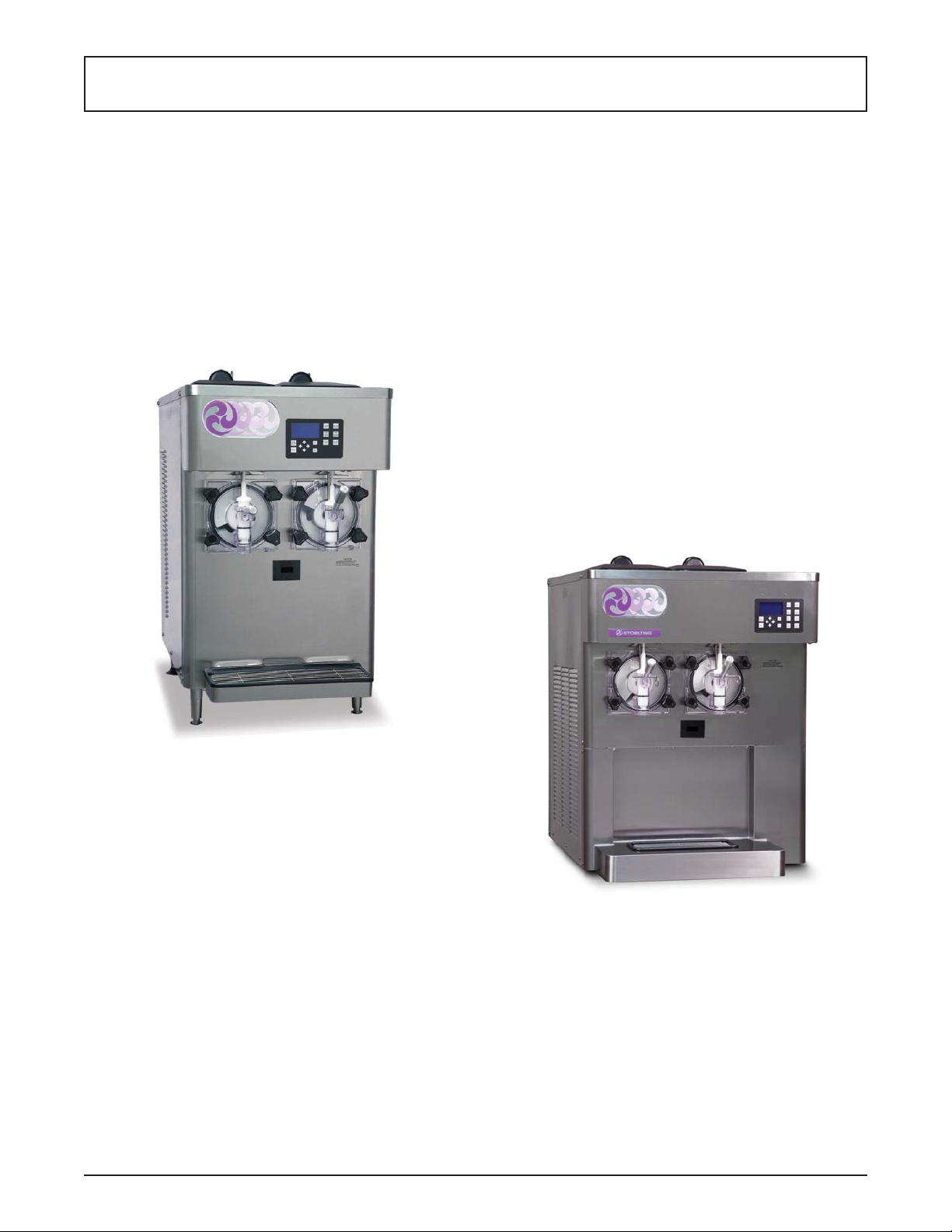
1.1 DESCRIPTION
The Stoelting E122 & F122 countertop machines are gravity fed. The machines are equipped with fully automatic
controls to provide a uniform product. This manual is
designed to help qualifi ed service personnel and opera-
tors with the installation, operation and maintenance of
the Stoelting E122 & F122 gravity machines.
Figure 1-1 Model E122
Figure 1-1 Model F122
Owner’s Manual #513667 Rev.3 1 E122 & F122 Model Machines
Page 8
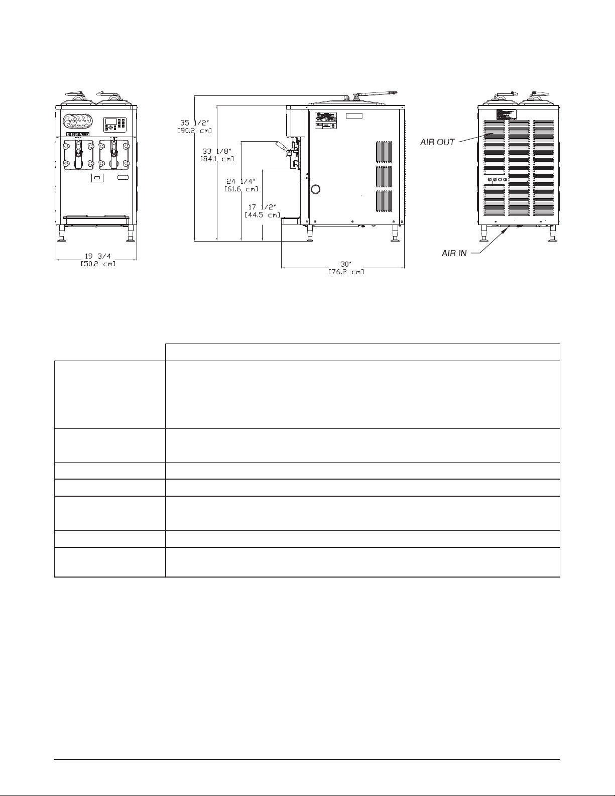
1.2 SPECIFICATIONS
Model E122
Dimensions Machine
width 19-5/8’’ (49,8 cm)
height 35-1/2’’ (90,2 cm)
depth 30-1/4’’ (76,8 cm)
Electrical 1 Phase, 208-240 VAC, 60Hz
connection type NEMA5-15P power cord provided
Compressor 5,500 Btu/hr
Drive Motor Two - 1/3 hp
Air Flow Air cooled units require 4” (10,2 cm) air space in back
Hopper Volume Two - 3 gallon (11,36 liters)
Freezing Cylinder
Volume
Two - 1.25 gallon (4,73 liters)
Owner’s Manual #513667 Rev.3 2 E122 & F122 Model Machines
Page 9
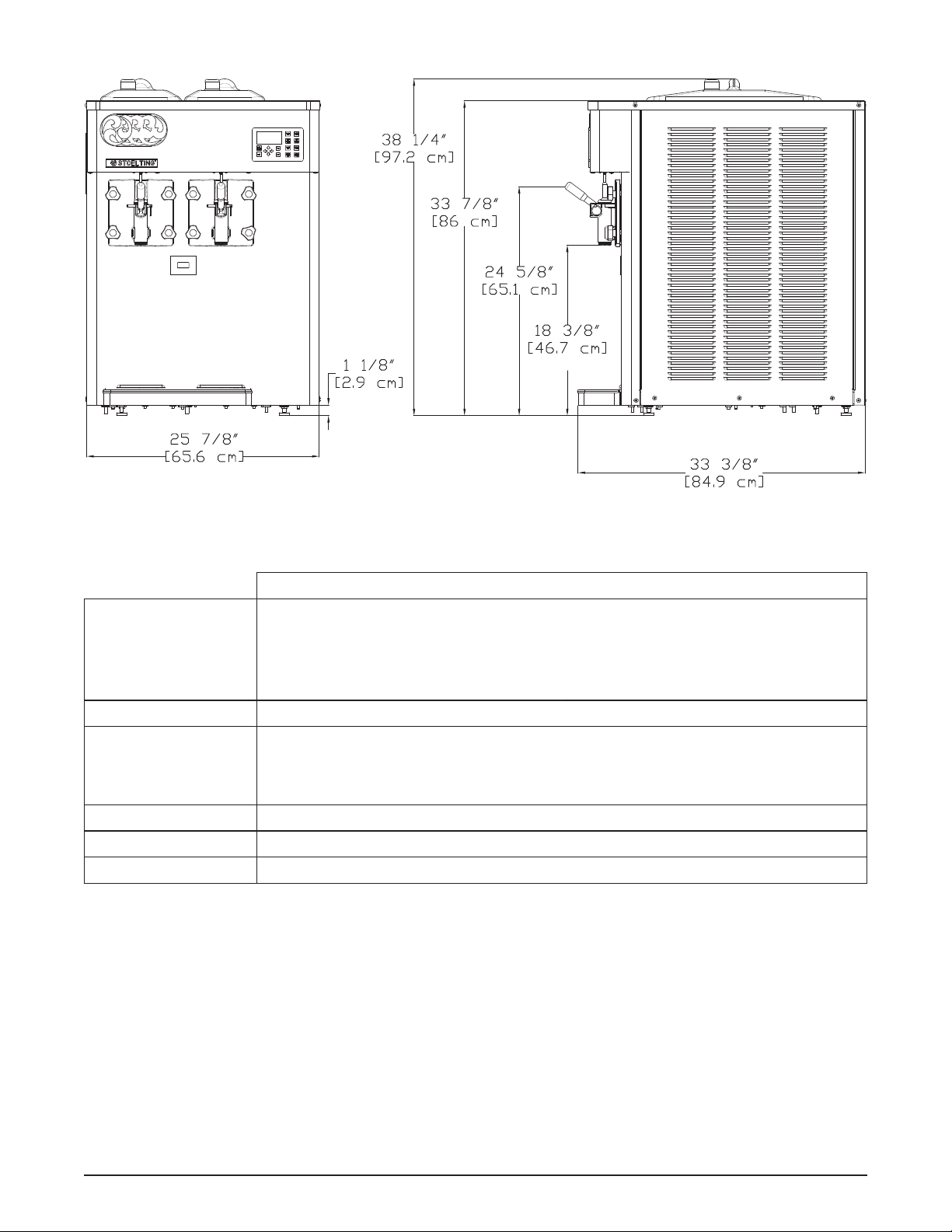
Model F122
Dimensions Machine with crate
width 25-7/8’’ (65,7 cm) 31-3/4’’ (80,6 cm)
height 38-1/4’’ (97,2 cm) 47-3/8’’ (120,3 cm)
depth 33-3/8’’ (84,8 cm) 41-1/4’’ (104,8 cm)
Weight 390 lbs (176,9 kg) 485 lbs (219,9 kg)
Electrical 1 Phase, 208-240 VAC, 60Hz
running amps 14.5A
connection type NEMA6-20P power cord provided
Compressor 12,000 Btu/hr
Drive Motor Two - 1/2 hp
Air Flow Air cooled units require 6” (15,24 cm) air space on both sides
Owner’s Manual #513667 Rev.3 3 E122 & F122 Model Machines
Page 10

Owner’s Manual #513667 Rev.3 4 E122 & F122 Model Machines
Page 11
SECTION 2
INSTALLATION INSTRUCTIONS
2.1 SAFETY PRECAUTIONS
Do not attempt to operate the machine until the safety
precautions and operating instructions in this manual are
read completely and are thoroughly understood.
Take notice of all warning labels on the machine. The labels have been put there to help maintain a safe working
environment. The labels have been designed to withstand
washing and cleaning. All labels must remain legible for
the life of the machine. Labels should be checked periodically to be sure they can be recognized as warning labels.
If danger, warning or caution labels are needed, indicate
the part number, type of label, location of label, and quantity
required along with your address and mail to:
STOELTING
ATTENTION: Customer Service
502 Hwy. 67
Kiel, Wisconsin 53042
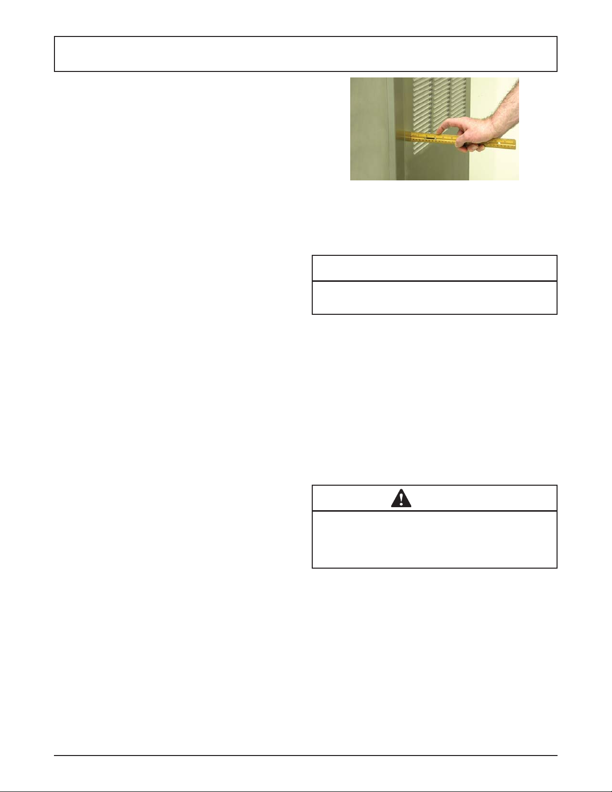
Figure 2-1 Space and Ventilation Requirements
E. Correct ventilation is required. The machine
requires 6” clearance on both sides for proper
air fl ow.
CAUTION
Failure to provide adequate ventilation will void
warranty.
2.2 SHIPMENT AND TRANSIT
The machine has been assembled, operated and inspected
at the factory. Upon arrival at the fi nal destination, the
entire machine must be checked for any damage which
may have occurred during transit.
With the method of packaging used, the machine should
arrive in excellent condition. THE CARRIER IS RESPONSIBLE FOR ALL DAMAGE IN TRANSIT, WHETHER
VISIBLE OR CONCEALED. Do not pay the freight bill
until the machine has been checked for damage. Have
the carrier note any visible damage on the freight bill. If
concealed damage and/or shortage is found later, advise
the carrier within 10 days and request inspection. The
customer must place claim for damages and/or shortages
in shipment with the carrier. Stoelting cannot make any
claims against the carrier.
2.3 MACHINE INSTALLATION
Installation of the machine involves moving the machine
close to its permanent location, removing all crating, setting in place, assembling parts, and cleaning.
A. Uncrate the machine.
B. Determine the location of the machine. The
location must be able to hold 470 lbs.
C. Accurate leveling is necessary for correct drainage
of the machine barrel and to insure correct overrun.
Place a bubble level on top of the machine at each
corner to check for level condition. If adjustment
is necessary, level the machine by turning the
bottom part of each leg in or out.
F. Connect the power cord to the proper power
supply . Check the nameplate on your machine for
proper supply. The unit must be connected to a
properly grounded receptacle. The electrical cord
furnished as part of the machine has a three prong
grounding type plug. The use of an extension
cord is not recommended, if necessary use one
with a size 12 gauge or heavier with ground wire.
Do not use an adapter to get around grounding
requirement.
WARNING
Do not alter or deform electrical plug in any way.
Altering the plug to fi t into an outlet of dif ferent con-
fi guration may cause fi re, risk of electrical shock,
product damage and will void warranty.
Owner’s Manual #513667 Rev.3 5 E122 & F122 Model Machines
Page 12
2.4 AUTO FILL PUMP INSTALLATION
The auto fi ll pumps are powered by water and have a
fi xed orifi ce that delivers water and syrup to the machine
at an exact ratio. The auto fi ll kit is designed for use with
Bag In Box (BIB) concentrated syrup.
Follow these instructions to properly install the pump.
Repeat for each side.
A. Route the clear tubing with the BIB connector
to the BIB. If there is excess tubing, trim it and
reconnect it to the BIB connector.
B. Route the water line tubing to the shutoff valve of
the water supply . Trim excess tubing and connect
it to the shutoff valve.
C. Route the water line and syrup line tubing (3/8”
braided tubing) from the pump to the machine.
D. Route the water line tubing to the tube exiting the
rear panel. Trim excess tubing and connect.
E. Route the syrup line to the tubing connected to
the adapter on the hopper cover. Trim excess
tubing and connect.
F. Check that the clear tubing coming out of the
rear panel is connected to the plug in the hopper
cover. If not, connect it using a clamp in the kit.
G. Check that all tubing connections are properly
clamped, fi ttings are tightened and the tubing is
not kinked.
to
machine
to
BIB
water inlet
from shut-
off valve
syrup inlet
from BIB
Figure 2-3 Top View of Pump
water outlet
to machine
this side
of pump is
mounted to
the BIB shelf
syrup outlet
to machine
2.6 INTELLITEC2™ SETUP
PRIOR TO INSTALLATION
A. Locate a copy of the service contact fi le (info.txt).
B. Modify the info.txt fi le with information from the
service company using the instructions in the fi le.
C. Put the service contact fi le onto the root level of
a USB fl ash drive (do not put the fi les into any
folder).
SETTING MODEL INFORMATION
A. Press the Main Power button.
B. The display will ask if the machine is an E122 or
F122. Use the arrow buttons to move the cursor
to the correct model and press the SEL button.
SETTING CONTACT INFORMATION
A. Plug your USB fl ash drive into the control if it is
not already plugged in.
B. From the Current Status screen, press the left
arrow button to access the passcode selection
screen. Press the right arrow, SET, and then the
SEL button.
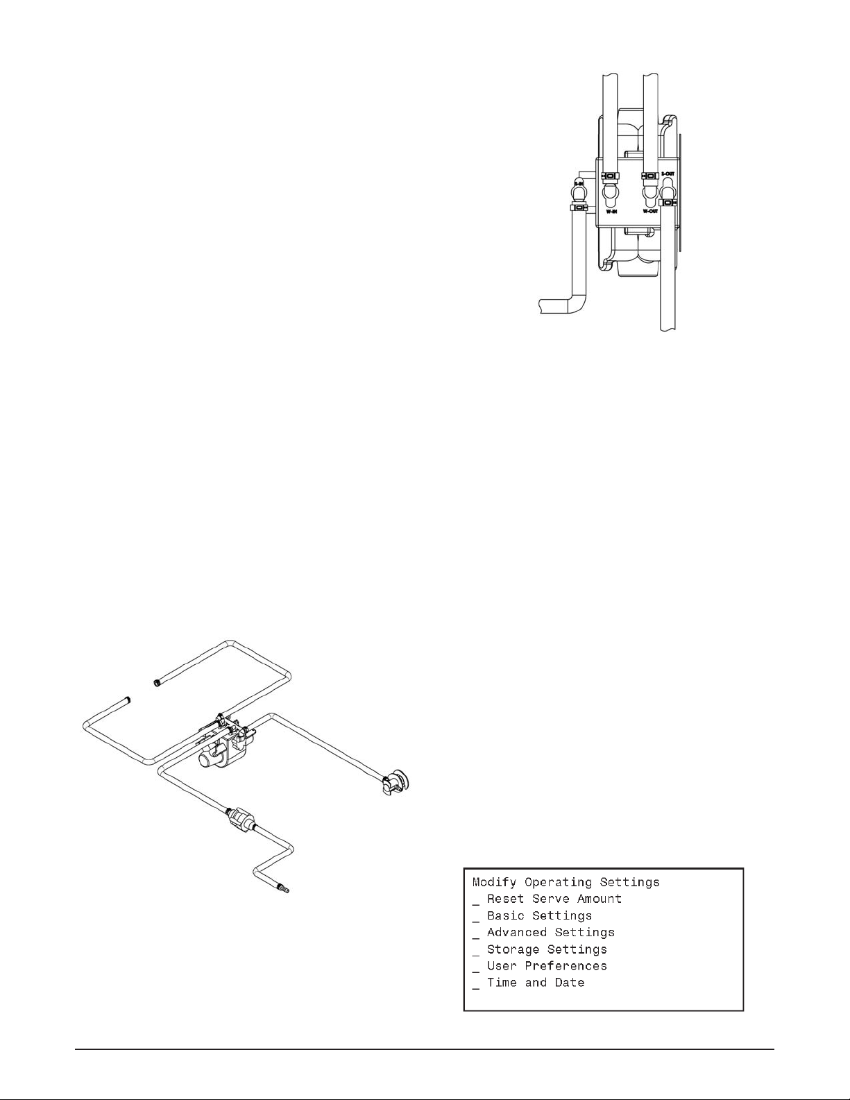
C. After the password is accepted, use the arrows to
move the cursor to the Modify Settings option and
press the SEL button. Then move the cursor to
the User Preferences and press the SEL button.
water
inlet
Figure 2-2 Auto Fill Pump Tubing Layout
Figure 2-4
Owner’s Manual #513667 Rev.3 6 E122 & F122 Model Machines
Page 13

D. On the User Preferences screen move the cursor
to the Contact Information USB Update and press
the SEL button.
Figure 2-5
E. The screen will change and show “File Found” for
a quick second while it updates the information.
F . After updating the contact information, the screen
will show the Service Contact Information page.
SETTING TIME AND DATE
A. Press the right arrow button.
B. Move the cursor to the Modify Settings option
and press the SEL button. Then move the cursor
to the Time and Date option and press the SEL
button and adjust the settings as required.
1. Press the SEL button to enter the Modify
Time and Date screen.
2. Move the cursor to the setting that needs
to be changed and press the SET button.
3. Use the arrow buttons to change the
setting and press the SET button to save the
change.
Figure 2-6
G. Press the left arrow button to go back to the Current
Status screen and remove the USB fl ash drive.
Figure 2-7
C. Press the left arrow button until the Current Status
screen is displayed.
Owner’s Manual #513667 Rev.3 7 E122 & F122 Model Machines
Page 14

Owner’s Manual #513667 Rev.3 8 E122 & F122 Model Machines
Page 15

SECTION 3
INITIAL SET-UP AND OPERATION
3.1 OPERATOR’S SAFETY PRECAUTIONS
SAFE OPERATION IS NO ACCIDENT; observe these
rules:
A. Know the machine. Read and understand the
Operating Instructions.
B. Notice all warning labels on the machine.
C. Wear proper clothing. Avoid loose fi tting garments,
and remove watches, rings or jewelry that could
cause a serious accident.
D. Maintain a clean work area. Avoid accidents by
cleaning up the area and keeping it clean.
E. Stay alert at all times. Know which switch, push
button or control you are about to use and what
effect it is going to have.
F . Disconnect electrical cord for maintenance. Never
attempt to repair or perform maintenance on the
machine until the main electrical power has been
disconnected.
G. Do not operate under unsafe operating conditions.
Never operate the machine if unusual or excessive
noise or vibration occurs.
3.2 OPERATING CONTROLS AND INDICATORS
Before operating the machine, it is required that the operator know the function of each operating control. Refer to
Figure 3-1 for the location of the operating controls on the
machine. For information regarding error codes displayed
on the control panel, refer to the troubleshooting section
of this manual.
WARNING
High voltage will shock, burn or cause death. Make
sure the display shows the freezing cylinders and
pump are off. If they are not, press the On/Off button
and Pump button to turn them off prior to disassembling for cleaning or servicing. Do not operate
machine with panels removed.
IntelliT ec2
Consistency
Adjustment
Screw
Figure 3-1 F122 Controls
Owner’s Manual #513667 Rev.3 9 E122 & F122 Model Machines
Control
Page 16

Figure 3-2 IntelliTec2 Control
A. INTELLITEC2 TOUCHPAD
Main Power On/Off
The Main Power button is used to supply power to the
IntelliTec2 control, the freezing cylinder circuits and the
storage refrigeration system. When the machine is fi rst
plugged in, the control defaults to the On status with power
to the hoppers only. If the Main Power On/Off button is
pressed when the machine is on, the machine will turn
off and a status message will be displayed on the screen.
Help
Pressing the Help button will display help information
dependant on the cursor’s location. Pressing the Help
button again will exit the help screen.
Selection Button (SEL)
The SEL button is used by service technicians to select
menu options.
Set Button (SET)
The SET button is used by service technicians to save
changes when modifying control settings.
On/Off Button
Power to the freezing cylinders is controlled with the On/
Off Left and On/Off Right buttons.
Push to Freeze Button
Pressing the PUSH TO FREEZE button initiates “Serve
Mode”.
Clean Button
The CLEAN button initiates “Clean Mode”.
Pump Button
The Pump On/Off buttons control power to the solenoids
for the autofi ll system.
Arrow Buttons ()
The arrow buttons are used by service technicians to
navigate through the control readings and settings.
B. SPIGOT SWITCH
The spigot switch will automatically start the auger drive
and refrigeration systems when the spigot is opened to
dispense product. When the spigot is closed, the drive
motor and compressor will remain on until the product
in the freezing cylinder reaches the proper consistency.
C. CONSISTENCY ADJUSTMENT SCREW
The Consistency Adjustment Screw increases or decreases product consistency . A tension spring is connected to
the screw and changes the amount of torque needed to
complete a refrigeration cycle. Turn the knob clockwise
to increase consistency or counterclockwise to decrease
consistency.
C. HOPPER PROBES
The mix level in the hoppers is controlled by two probes.
When mix in the hopper gets below the long probe, the
autofi ll solenoid opens and the hopper fi lls. When the mix
level reaches the short probe, the autofi ll solenoid closes.
3.3 REMOVING MIX FROM MACHINE
To remove the mix from the machine, refer to the following steps:
A. Wash, rinse, dry and sanitize hands before
starting.
B. Press the Pump On/Off button to turn the autofi ll
pump off.
C. Make sure the display shows the freezing cylinder
is off. If it is not, press the On/Off Left or On/Off
Right button to turn it off.
D. Press the Clean button and drain the mix from
the freezer into a bucket. Once drained, stop the
cleaning cycle by pressing the Clean button.
E. Fill the hopper with 2 gallons of clean, cold water .
F . Press the Clean button. Run the machine in Clean
mode for approximately 5 minutes. Continue to
the next step while the machine is cleaning.
G. Prepare Stera-Sheen Green Label Sanitizer
according to manufacturer’s instructions to
provide a 100ppm strength solution. In a clean
bucket, mix 1 packet of sanitizer and 2 gallons
of cold water. Check the chlorine content with a
test strip to ensure 100ppm strength.
H. After 5 minutes, drain the water from the machine
into a bucket and discard the water. Press the
Clean button to stop the cleaning cycle.
NOTE
If the water does not drain clear, repeat the steps.
I. Fill the hopper with the 2 gallons of sanitizer
solution.
J. Press the clean button. Run the machine in Clean
mode for approximately 5 minutes.
Owner’s Manual #513667 Rev.3 10 E122 & F122 Model Machines
Page 17

Figure 3-3 Remove Spigot Pin
K. After 5 minutes, drain the sanitizer solution from
the machine into a bucket and discard the solution.
3.4 DISASSEMBLY OF MACHINE PARTS
Inspect for worn or broken parts each time the machine
is disassembled. Replace any worn or broken parts to
ensure safety to both the operator and the customer and
to maintain good machine performance and a quality
product. Frequency of cleaning must comply with the
local health regulations.
T o disassemble the machine, refer to the following steps:
WARNING
High voltage will shock, burn or cause death. Make
sure the display shows the freezing cylinders and
pump are off. If they are not, press the On/Off button
and Pump button to turn them off prior to disassembling for cleaning or servicing. Do not operate
machine with panels removed.
A. Pull out the spigot pin by its ring. Remove the
spigot handle.
Figure 3-5 Removing O-Ring
B. Remove front door by turning the circular knobs
and then pulling door off the studs.
NOTE
When removing front door, entire door and stator
assembly will come out as well.
C. Remove the torque rod from the stator assembly.
D. Remove the quad ring from the groove in front
door.
E. Remove the stator bar. Remove the small white
bushing.
F. Remove the o-rings at the front and back of the
stator bar by fi rst wiping off the lubricant using
a clean paper towel. Then squeeze the o-ring
upward with a dry cloth. When a loop is formed,
roll the o-ring out of the groove.
G. Remove the auger support bushing.
H. Turn the spigot body until the ice breaker bar can
be removed. Remove breaker bar.
I. Remove the spigot body from the front door.
J. Remove the o-rings (2) from the spigot.
K. Remove the auger assembly from the freezing
cylinder and remove the auger blade. Remove
the rear seal and o-ring from the auger.
L. Remove the drain tray, drip tray and drip tray grid.
M. Remove the hopper cover and disconnect the
autofi ll adapter from the cover by pulling out the
retaining clip.
Figure 3-4 Spigot and Ice Breaker Bar Removal
Owner’s Manual #513667 Rev.3 11 E122 & F122 Model Machines
Page 18

3.5 CLEANING AND SANITIZING THE
MACHINE PARTS
Place all loose parts in a pan or container and take to
the wash sink for cleaning. Local and state health codes
dictate the procedure required. Some health codes require
a four-sink process (pre-wash, wash, rinse, sanitize, and
air-dry), while other codes require a three-sink process
(without the pre-wash step). The following procedures
are a general guideline only . Consult your local and state
health codes for procedures required in your location.
A. Set up a 3-compartment sink with wash, rinse and
sanitize compartments. Use Stera-Sheen Green
Label or equivalent. Prepare sanitizer according
to manufacturer’s instructions to provide a 100ppm
strength solution. Set aside a small amount of
sanitizer
B. Clean all parts using brushes provided.
C. After cleaning, remove the parts and let air dry.
D. Sanitize the hopper and freezing cylinder with
sanitizer. Be sure to clean the rear seal surfaces
inside the freezing cylinder.
E. Wipe down the outside of the machine and table
with a yellow sanitized towel.
CAUTION
Do not allow sanitizer to remain in contact with
stainless steel parts for prolonged periods. Prolonged contact of sanitizer with machine may cause
corrosion of stainless steel parts.
3.6 ASSEMBLY OF MACHINE
T o assemble the machine parts, refer to the following steps:
NOTE
Petrol Gel sanitary lubricant or equivalent must be
used when lubrication of parts is specifi ed.
NOTE
The United States Department of Agriculture and
the Food and Drug Administration require that lubricants used on food processing equipment be certifi ed for this use. Use lubricants only in accordance
with the manufacturer’s instructions.
A. Wash, rinse, dry and sanitize hands before
starting.
B. Place the rear seal o-ring onto the auger and
apply a thin fi lm of Petrol-Gel to the o-ring.
C. Assemble the rear seal onto the auger with the
large end of the seal to the rear. Lubricate the hex
end of the auger with a small amount of spline
lubricant.
D. Install the plastic auger blade onto the auger. Push
the auger into the freezing cylinder and rotate it
slowly until the auger engages the drive shaft.
E. Assemble the o-rings onto the spigot body and
apply a thin fi lm of Petrol-Gel onto the o-rings.
F. Insert the spigot body into the front door.
Torque
Rod
Auger
Support
Bushing
Stator Bar
Front O-Ring
Figure 3-6 Door and Stator Assembly
Owner’s Manual #513667 Rev.3 12 E122 & F122 Model Machines
Stator Bar
Bushing
Stator Bar
Stator Bar
Rear O-Ring
Quad
Ring
Page 19

NOTE
When inserting the spigot body, press the o-rings
against the spigot to prevent damage.
G. Turn the spigot body until the ice breaker bar can
be inserted. Insert the ice breaker bar and rotate
spigot body 90°.
H. Apply Petrol-Gel to the inside and outside of the
front auger support bushing. Install the bushing
onto the front door so the beveled edge of the
bushing is against the door.
I. Install the large quad ring into the groove in the
front door.
J. Install the o-rings at the front and back of the
stator bar. Apply a thin fi lm of Petrol-Gel onto
the o-rings. Install the small white bushing to the
stator bar.
K. Insert the stator bar into the front door and insert
the torque rod through the hole in the stator bar.
L. Install the front door onto the freezer. Install the
knobs onto the studs.
NOTE
When installing the front door, the torque rod must
be placed in the center notch of the torque actuator arm.
M. Insert the spigot handle so the hole lines up and
insert the spigot pin.
N. Install the drain tray, drip tray and drip tray grid.
3.7 SANITIZING
Sanitizing must be done after the machine is cleaned and
just before the hopper is fi lled with mix. Sanitizing the night
before is not effective. However , you should always clean
the machine and parts after each use.
The United States Department of Agriculture and the Food
and Drug Administration require that all cleaning and
sanitizing solutions used with food processing equipment
be certifi ed for this use.
When sanitizing the machine, refer to local sanitary regulations for applicable codes and recommended sanitizing
products and procedures. The frequency of sanitizing
must comply with local health regulations.
Mix sanitizer according to manufacturer’s instructions to
provide a 100 parts per million (ppm) strength solution and
check the solution with chlorine test strips. Mix sanitizer
in quantities of no less than 2 gallons (7.5 liters) of 90°
to 110°F (32° to 43°C) water. Allow sanitizer to contact
the surfaces to be sanitized for 5 minutes. Any sanitizer
must be used only in accordance with the manufacturer’s
instructions.
In general, sanitizing may be conducted as follows:
CAUTION
Do not allow sanitizer to remain in contact with
stainless steel parts for prolonged periods. Prolonged contact of sanitizer with machine may cause
corrosion of stainless steel parts.
A. Prepare Stera-Sheen Green Label Sanitizer
or equivalent according to manufacturer’s
instructions to provide a 100ppm strength solution.
In a clean bucket, mix 1 packet of sanitizer and 2
gallons of cold water. Check the chlorine content
with a test strip to ensure 100ppm strength.
B. Pour the sanitizing solution into the hopper.
C. Press the Main Power On/Off button and press
the Clean button to start the cleaning cycle.
D. Use a sanitized barrel brush to sanitize the hopper
sides and hopper cover with the sanitizer solution
in the hopper.
E. After 5 minutes, drain the sanitizer solution from
the machine into a bucket and discard the solution.
Leave a small amount of sanitizer solution in the
freezing cylinder.
F. Place Clean button to stop the cleaning cycle.
G. Collect the remaining sanitizer in a clean cup and
check the chlorine content with a test strip. If the
chlorine content is less than 100ppm, repeat the
sanitizing procedure. If the test strip does not
read 100ppm after the second test, repeat the
disassembly, cleaning and sanitizing procedures.
H. Connect the autofi ll adapter to the hopper cover
with the retaining clip and place the hopper cover
onto the hopper.
I. Press the Pump On/Off button to turn the pump
on.
J. Press the Push to Freeze button to start the
freezing cycle. Open the spigot to drain out any
remaining sanitizer into the a bucket. Close the
spigot when mix begins coming out.
Owner’s Manual #513667 Rev.3 13 E122 & F122 Model Machines
Page 20

3.8 FREEZE DOWN AND OPERATION
A. After the freezing cylinder is fi lled, product will be
ready to serve in 8 to 12 minutes.
B. To dispense, pull the spigot handle down to open
the spigot.
C. The machine is designed to dispense the product
at a reasonable draw rate. If the machine is
overdrawn, the result is a wet product or a product
that will not dispense at all. If this should occur,
allow the machine to run for approximately 30
seconds before dispensing additional product.
D. Do not operate the machine when the LOW MIX
message is displayed. Immediately check if the
autofi ll system is operating properly.
3.9 MIX INFORMATION
Mix can vary considerably from one manufacturer to another. Dif ferences in the quantity and quality of ingredients
have a direct bearing on the fi nished frozen product. A
change in machine performance that cannot be explained
by a technical problem may be related to the mix.
3.10 ROUTINE CLEANING
T o remove spilled or dried mix from the machine exterior ,
wash in the direction of the fi nish with warm soapy water
and wipe dry. Do not use highly abrasive materials as
they will mar the fi nish.
D. QUARTERLY
The air-cooled condenser is a copper tube and aluminum
fi n type. Condensing is totally dependent upon airfl ow .
A plugged condenser fi lter, condenser, or restrictions in
the louvered panel will restrict airfl ow. This will lower the
capacity of the system and damage the compressor.
The condenser must be kept clean of dirt and grease.
The machine must have a minimum of 6” (15.2 cm) of
ventilation on both sides of the unit for free fl ow of air.
The condenser and condenser fi lter require periodic clean-
ing. To clean, refer to the following procedures.
E122 Air Cooled Condenser Cleaning
A. Partially unscrew the knob located on the
underside of the machine. The knob holds the
fi lter bracket which does not need to be detached
to remove the fi lter.
B. Remove the fi lter.
C. Visually inspect the condenser fi lter for dirt.
D. If the fi lter is dirty, vacuum or brush clean, rinse
with clean water and allow to dry before replacing
on the machine.
3.11 PREVENTIVE MAINTENANCE
Stoelting recommends that a maintenance schedule be
followed to keep the machine clean and operating properly.
B. DAILY
1. The exterior should be kept clean at all times to
preserve the luster of the stainless steel. A mild
alkaline cleaner is recommended. Use a soft cloth
or sponge to apply the cleaner.
C. WEEKLY
1. Check o-rings and rear seal for excessive wear
and replace if necessary.
2. Remove the drip tray by gently lifting up to
disengage from the support and pulling out. Clean
behind the drip tray and front of the machine.
Air Filter
Knob
Figure 3-7 E122 Condenser Filter Removal
Owner’s Manual #513667 Rev.3 14 E122 & F122 Model Machines
Page 21

Figure 3-8 F122 Condenser Filter Removal
F122 Air Cooled Condenser Cleaning
A. Remove the Phillips head screws from the right
side panel, and then remove the panel.
B. T o remove the condenser fi lter, grasp the top and
pull off. Visually inspect for dirt. If the fi lter is dirty,
shake or brush excess dirt off the fi lter and wash
in warm, soapy water. Once the fi lter is clean rinse
thoroughly in warm, clear water and shake dry,
taking care not to damage the fi lter in any way.
C. Visually inspect the condenser for dirt by shining
a light through the coil from the back (inside) of
the condenser.
D. If the condenser is dirty, place a wet towel over
the front (outside) of the condenser.
E. Using a vacuum, carefully clean the condenser
coil from the inside and outside of the machine.
A stif f bristled brush may help in releasing debris
from between the condenser coils.
E. SEMI-ANNUALLY
1. Disconnect the machine from the power source.
2. Check drive belt for proper tension. Push belt in
with one fi nger, belt should defl ect about 3/8”.
3. Lubricate condenser fan motor with S.A.E. 20
weight oil. Three to six drops is required.
4. Sanitize the autofi ll system following the steps
below:
AUTOFILL SANITIZING
A. If necessary , disassemble, clean and sanitize the
machine.
NOTE
If the machine does not require cleaning and sanitizing, press the Pump On/Off button to turn off the
pump. Then dispense enough product so that the
mix level in the hopper is below the long probe. If
the mix level is above the long probe, the solenoid
will not activate and the pump will not operate.
B. Prepare Stera-Sheen Green Label Sanitizer
or equivalent according to manufacturer’s
instructions to provide a 100ppm strength solution.
Mix the sanitizer in quantities of no less than 2
gallons of 90° to 1 10°F (32° to 43°C) water . Any
sanitizer must be used only in accordance with
the manufacturer’s instructions.
C. Cut an adapter from an empty bag of syrup.
Connect the adapter to the BIB connector of the
syrup line. Put the BIB connector into the bucket
of sanitizer.
NOTE
If you do not have an empty bag of syrup, remove
the plug from the top of the BIB connector. Do not
lose the plug; it is needed for proper operation of
the BIB.
D. Make sure the display screen shows that the
main power is on. Hold the hopper cover over a
bucket and press the Pump On/Off button. The
solenoid will activate and the brix pump will pump
sanitizer into the bucket.
NOTE
The solenoid will only activate when there is not any
liquid touching the longer mix probe in the hopper.
E. After all the sanitizer has run through the pump,
press the Pump On/Off button to turn off the pump.
F . Disconnect the bag adapter from the BIB connector
(or reinsert the plug into the connector). Connect
the BIB connector to the syrup BIB.
G. Hold the hopper cover over a bucket and press the
Pump On/Off button. This will fl ush the sanitizer
out of the pump and tubing. Once the sanitizer
is fl ushed out, press the Pump On/Off button.
H. The pump is now ready to operate. Place the
hopper cover on the hopper.
Owner’s Manual #513667 Rev.3 15 E122 & F122 Model Machines
Page 22

3.12 EXTENDED STORAGE
Refer to the following steps for storage of the machine
over any long period of shutdown time:
A. Follow the cleaning and sanitizing procedures
for the machine and follow the semi-annual
instructions to sanitize the autofi ll system.
B. Press the Main Power On/Off button so that power
to the machine is off.
C. Disconnect (unplug) from the electrical supply
source.
D. Thoroughly clean all parts that come in contact
with mix. Rinse in clean water and dry parts. Do
not sanitize.
NOTE
Do not leave cleaning solution in the hopper or in
the freezing cylinder during the shutdown period.
E. Remove, disassemble and clean the front door,
mix inlet regulator and auger parts.
Owner’s Manual #513667 Rev.3 16 E122 & F122 Model Machines
Page 23

SECTION 4
TROUBLESHOOTING
4.1 ERROR CODES
When the machine experiences a problem, one of the
following error codes will be displayed on the control
panel. Each error code directs you to the system location
of the malfunction.
ERROR CODE MALFUNCTION
2 High Torque
3 Run Time
4 Clean
5 Freezing Cylinder Sensor
6 Hopper Sensor (single hopper machines)
7 Drive Motor
8 Cab Sensor
9 High Pressure Cutout
10 Auxiliary Sensor
11 Prime (cab units only)
12 Left Hopper Sensor
13 Right Hopper Sensor
21 Spigot Open Time
To return the machine to normal operation, any error
causing condition must be corrected and the power to
the affected freezing cylinder must be cycled. Turn the
power to the freezing cylinder off then back on using the
On/Off button of the affected freezing cylinder.
4.2 TROUBLESHOOTING ERROR CODES
Error Code 2 - High Torque
If the control panel displays a High Torque Error
(E2), the controller has sensed that the drive motor
is running at a high load for 10 or more seconds.
This may be due to the product consistency
adjustment being set too high. Press the On/Off
button for the cylinder to turn it off, wait until the
product in the freezing cylinder thaws and then
turn the cylinder back on. If the error persists,
contact your Authorized Stoelting Distributor for
further assistance.
Error Code 3 - Run Time
The Run Time Error (E3) occurs when the
compressor runs continuously for an extended
period. This error is often caused by very low
mix levels in the hopper. Make sure the autofi ll
system is fi lling the hopper properly.
In air cooled machines, the Run Time Error
may indicate that airfl ow within the machine
has reduced or stopped. Check the sides of the
machine for anything that would restrict airfl ow.
If the error persists after attempting to clear it,
contact your Authorized Stoelting Distributor for
further assistance.
NOTE
When the machine encounters a Run Time Error,
the machine will continue to run using preset timers. This mode will allow the operator to continue
serving product until the machine can be serviced.
Error Code 4 - Clean
If the machine is left in the Clean Mode for more
than 20 minutes, the control panel will display a
Clean Error (E4). This condition does not refl ect a
problem with the machine itself. The Clean Error
has been programmed into the controller as a
safeguard to protect the machine from potential
damage caused by the machine being accidentally
left in "Clean Mode". To clear the Clean Error,
press the On/Off button for the cylinder to turn if
off then back on.
Error Code 5 - Freezing Cylinder Sensor
The Freezing Cylinder Sensor Error (E5) indicates
a failure of the barrel sensor or if the sensor is
out of range. If the control panel displays an E5,
press the On/Off button for the cylinder to turn
if off then back on. If the error persists, contact
your Authorized Stoelting Distributor for further
assistance.
NOTE
When the machine encounters a Freezing Cylinder
Sensor Error, the machine will continue to run using
preset timers. This mode will allow the operator to
continue serving product until the machine can be
serviced.
Owner’s Manual #513667 Rev.3 17 E122 & F122 Model Machines
Page 24

Error Code 6 - Hopper Sensor (single hopper machines)
The Hopper Sensor Error (E6) will not occur on
the machine.
Error Code 7 - Drive Motor
If the control panel displays a Drive Motor Error
(E7), the control does not sense current coming
from the drive motor. Press the On/Off button
for the cylinder to turn if off then back on. If the
error persists, contact your Authorized Stoelting
Distributor for further assistance.
Error Code 8 - Cab Sensor
A Cab Sensor Error (E8) will not occur on the
machine.
Error Code 9 - High Pressure Cutout
A High Pressure Cutout Error (E9) will not occur
on the machine.
Error Code 10 - Auxiliary Sensor
An Auxiliary Temperature Sensor Error (E10)
occurs if the temperature sensor on the control
board fails. Press the On/Off button for the cylinder
to turn if off then back on. If the error persists,
contact your Authorized Stoelting Distributor for
further assistance
Error Code 11 - Prime Error
The Prime Error (E11) will not occur on the
machine.
Error Code 12 - Left Hopper Sensor
The Left Hopper Sensor Error (E12) indicates
a failure of the hopper sensor or if the sensor is
out of range. If the control panel displays an E12,
press the On/Off button for the cylinder to turn
if off then back on. If the error persists, contact
your Authorized Stoelting Distributor for further
assistance.
Error Code 13 - Right Hopper Sensor
The Right Hopper Sensor Error (E13) indicates
a failure of the hopper sensor or if the sensor is
out of range. If the control panel displays an E12,
press the On/Off button for the cylinder to turn
if off then back on. If the error persists, contact
your Authorized Stoelting Distributor for further
assistance.
Error Code 21 - Spigot Open Time
The Spigot Open Time Error (E21) indicates a
failure of the spigot switch. If the control senses
the spigot is open continuously for 10 minutes, the
machine will go into Sleep 3 mode. If the control
panel displays an E21, press the On/Off button
for the cylinder to turn if off then back on. If the
error persists, contact your Authorized Stoelting
Distributor for further assistance.
Owner’s Manual #513667 Rev.3 18 E122 & F122 Model Machines
Page 25

4.3 TROUBLESHOOTING - MACHINE
PROBLEM POSSIBLE CAUSE REMEDY
1 Power to machine is off. 1 Supply power to machine.
Machine does not
run.
Machine will not
shut off.
Product is too fi rm.
Product is too thin.
Product does not
dispense.
Drive belt slipping
or squealing.
Rear auger seal
leaks.
Front door leaks.
2 Freeze-up (auger will not turn). 2 Turn off barrel for 15 minutes by pressing the
On/Off Left or On/Off Right button, then restart.
3 Front door not in place. 3 Assemble front door in place.
1 Consistency temperature setting is too
fi rm.
2 Refrigeration problem. 2 Check system. (Call distributor for service)
1 Consistency temperature setting is too
fi rm.
1 No vent space for free fl ow of cooling
air.
2 Condenser is dirty. 2 Clean. (See Section 3)
3 Consistency setting too soft. 3 Turn Consistency Adjustment screw clockwise.
4 Auger is assembled incorrectly. 4 Remove mix, clean, reassemble, sanitize and
5 Auto Fill Pump not operating. 5 See Auto Fill Troubleshooting section.
6 Refrigeration problem. 6 Check system. (Call distributor for service)
1 No mix in hopper. 1 See Auto Fill Troubleshooting section.
2 Drive motor overload tripped. 2 Wait for automatic reset. (If condition
3 Drive belt failure. 3 Replace drive belt.
4 Freeze-up (Auger will not turn). 4 Turn off cylinder, wait for 15 minutes, then
1 Worn drive belt. 1 Replace drive belt.
2 Freeze-up (Auger will not turn). 2 Turn off cylinder, wait for 15 minutes, then
3 Not tensioned properly. 3 Adjust belt tension
1 Outside surface of rear auger seal is
lubricated.
2 Rear seal missing or damaged. 2 Check or replace.
3 Seal o-ring missing, damaged or
installed incorrectly.
4 Worn or scratched auger shaft. 4 Replace auger shaft.
1 Front door knobs are loose. 1 Tighten knobs.
2 Spigot parts are not lubricated. 2 See Section 3.
3 Chipped or worn spigot o-rings. 3 Replace o-rings.
4 O-rings or spigot installed wrong. 4 Remove spigot and check o-ring.
5 Inner spigot hole in front door nicked
or scratched.
1 Turn Consistency Adjustment screw counter-
clockwise.
1 Turn Consistency Adjustment screw counter-
clockwise.
1 A minimum of 6” of air space on both sides.
(See Section 2)
freeze down.
continues, call distributor for service.)
restart.
restart.
1 Clean lubricant from outside of rear seal and
thoroughly clean rear of freezing cylinder.
Lubricate inside of seal and reinstall.
3 Check or replace.
5 Replace front door.
Owner’s Manual #513667 Rev.3 19 E122 & F122 Model Machines
Page 26

4.4 TROUBLESHOOTING - AUTOFILL PUMP
PROBLEM POSSIBLE CAUSE REMEDY
1 Low water pressure. 1 Verify that there is adequate water pressure at
Pump does not
operate.
Syrup
concentration
incorrect
2 Restriction or plugged auto fi ll system. 2 Flush and sanitize the pump and tubing.
3 Empty BIB 3 Replace BIB
1 BIB connector is not connected to the
BIB properly.
2 Leak at the connections or in the
tubing.
3 Air in the BIB syrup container. 3 Remove the air from the BIB syrup container.
4 Pump is clogged with debris or
particulates.
the inlet fi tting (30-50 psi).
1 Check connection and reconnect if necessary.
2 Look for leaks at the connections and bubbles
in the tubing. Tighten clamps and replace
tubing if necessary.
4 Remove syrup valves and inspect for debris
or improper closing that would interfere with
operation.
Owner’s Manual #513667 Rev.3 20 E122 & F122 Model Machines
Page 27

5.1 DECALS AND LUBRICATION
Part Description Quantity
208135 Brush - 4” X 8” X 16” (Barrel) 1
208380 Brush - 1/4” X 3” X 14” 1
208401 Brush - 1” X 3” X 10” 1
236054 Cleaning Card - Auto Fill Pump Kit 1
236065 Card - Cleaning Instruction - E122 & F122 1
236066 Card - Cleaning Instruction - Brix Pump 1
324105 Decal - Caution Electrical Shock 1
324106 Decal - Caution Electrical Wiring Materials 1
324107 Decal - Caution Hazardous Moving Parts 1
324141 Decal - Caution Rotating Blades 1
324208 Decal - Attention Refrigerant Leak Check 1
324393 Decal - Stoelting Swirl Logo 1
324509 Decal - Cleaning Instruction 1
324548 Decal - Adequate Ventilation 6” 1
324594 Decal - Attention Heat Sensitive 2
324686 Decal - Danger Automatic Start 2
324804 Decal - Domed Stoelting Swirl (Header Panel) 1
324888 Decal - Fan Motor Reset 1
324901 Decal - Transformer Switch 1
324909 Decal - USB Port 1
324922 Decal - Assembly Check 1
324938 Decal - 4” Ventilation 1
508048 Lubricant - Spline (2 oz Squeeze Tube) 1
508135 Petrol Gel - 4 oz Tube 1
SECTION 5
REPLACEMENT PARTS
Owner’s Manual #513667 Rev.3 21 E122 & F122 Model Machines
Page 28

5.2 AUGER SHAFT AND FACEPLATE PARTS
624678
666786
F122 - 2203224
E122 - 2203555
F122 - 2183751
E122 - 2204226
624515
630053
2203370
624644
624645
2183099
2183444
570197
624545
2183449
F122 - 2202068
E122 - 2202181
625310
336551
2183447
Owner’s Manual #513667 Rev.3 22 E122 & F122 Model Machines
482019
Page 29

5.2 AUGER SHAFT AND FACEPLATE PARTS - CONTINUED
Part Description Quantity
336551 Door - Front 2
482019 Knob - Front Door (Black) 8
570197 Pin - Cotterless Clevis (Front Door) 2
624515-5 O-Ring - Stator Bar Rear (5 Pack) 2
624545-5 O-Ring - Stator Bar Front (5 Pack) 2
624644-5 O-Ring - Spigot Body (Bottom) (5 Pack) 2
624645-5 O-Ring - Spigot Body (Top) (5 Pack) 2
624678-5 O-Ring - Rear Seal - Black (5 Pack) 2
625310 Quad-Ring - Front Door - Black 2
630053 Rod - Torque Actuator 2
666786 Seal - Rear Auger - Black 2
2183099 Breaker Bar - Spigot Body 2
2183444 Bushing - Stator Support (Rear) 2
2183447 Handle Only - Spigot 2
2183449 Bushing - Front Auger Support 2
2183751 Blade - Scraper F122 - 2
2202068 Stator Bar F122 - 2
2202181 Stator Bar E122 - 2
2203224 Auger Shaft F122 - 2
2203370 Spigot Body 2
2203555 Auger Shaft E122 - 2
2204226 Blade - Scraper E122 - 2
Owner’s Manual #513667 Rev.3 23 E122 & F122 Model Machines
Page 30

5.3 HOPPER PARTS
E122 - 2187058
F122 - 2203206
2187918
624607
314453 or
2203078 (Auto Fill)
2187919
E122 - 417031
F122 - 417006
E122 - 744281
F122 - 744252
E122 - 744609
F122 - 744273
Part Description Quantity
314453 Cover - Hopper 2
417006 Grid - Drip Tray (Vinyl Coated Metal) F122 - 1
417031 Grid - Drip Tray E122 - 1
624607-5 O-Ring - Mix Inlet 4
744252 Tray - Drain F122 - 1
744281 Tray - Drain E122 - 1
744273 Tray - Drip F122 - 1
744609 Tray - Drip E122 - 1
2187058 Mix Inlet Regulator E122 - 2
2187918 Mix Inlet Assembly (Auto Fill) 2
2187919 Clip - Retaining (Mix Inlet) 2
2203078 Cover - Hopper (Autofi ll) 2
2203206 Mix Inlet Regulator F122 - 2
Owner’s Manual #513667 Rev.3 24 E122 & F122 Model Machines
Page 31

5.4 AUTO FILL PARTS
756222
756222
756221
600102
756222
292219
616116
375645
756222
Part Description Quantity
264100 Clamp - Oetiker Stepless (#17) 4
264101 Clamp - Oetiker Stepless (#15.7) 46
292219 Connector - Bag In Box 2
375645 Fitting - 3/8” x 3/8” 2
538463 Nut 4
600102 Pump - Brix (3:1 Ratio) 2
616116 Water Regulator 2
647660 Screw - 10-32 x 3/8” 4
739126 Tie Wrap - 15” 19
739127 Tie Wrap - 7” 4
756221 Tubing - 3/8” Clear 6’
756222 Tubing - 3/8” Braided 80’
Owner’s Manual #513667 Rev.3 25 E122 & F122 Model Machines
Page 32

Owner’s Manual #513667 Rev.3 26 E122 & F122 Model Machines
Page 33

SECTION 6
SPECIAL APPLICATIONS
Owner’s Manual #513667 Rev.3 27 E122 & F122 Model Machines
Page 34

Owner’s Manual #513667 Rev.3 28 E122 & F122 Model Machines
Page 35

Re: Application of Stoelting F122 and Arctic Quake Non-Dairy concentrate product
Welcome to Arctic Quake
Stoelting’s policy regarding cleaning of the equipment is that for the frequency of
cleaning the freezer and freezer parts the end-user should refer to their state and local
health regulations.
Stoelting Foodservice equipment does go through NSF testing and subsequent NSF approval.
During the NSF testing and approval, Stoelting’s machines are tested and approved for
“cleanability” not for frequency of cleaning.
In the application of this type of freezer, customers using the Arctic Quake products
have a cleaning cycle of 5-14 days. In staying within this type of cleaning schedule,
the machine will function properly.
Owner’s Manual #513667 Rev.3 29 E122 & F122 Model Machines
Page 36

Owner’s Manual #513667 Rev.3 30 E122 & F122 Model Machines
Page 37

SECTION 7
WARRANTY
Owner’s Manual #513667 Rev.3 31 E122 & F122 Model Machines
Page 38

Owner’s Manual #513667 Rev.3 32 E122 & F122 Model Machines
Page 39

WARRANTY
FROZEN UNCARBONATED BEVERAGE EQUIPMENT
1. Scope:
PW Stoelting, L.L.C. (“Stoelting”) warrants to the first user (the “Buyer”) that the evaporator assembly,
compressors, drive motors, and speed reducers of Stoelting frozen uncarbonated beverage
equipment will be free from defects in materials and workmanship under normal use and proper
maintenance appearing within five (5) years, and that all other components of such equipment
manufactured by Stoelting will be free from defects in material and workmanship under normal use
and proper maintenance appearing within twelve (12) months after the date that such equipment is
originally installed.
2. Disclaimer of Other Warranties:
THIS WARRANTY IS EXCLUSIVE; AND STOELTING, HEREBY DISCLAIMS ANY
IMPLIED WARRANTY OF MERCHANTABILITY OR FITNESS FOR PARTICULAR
PURPOSE.
3. Remedies:
Stoelting’s sole obligations, and Buyer’s sole remedies, for any breach of this warranty shall be the
repair or (at Stoelting’s option) replacement of the affected component at Stoelting’s plant in Kiel,
Wisconsin, or (again, at Stoelting’s option) refund of the purchase price of the affected equipment,
and, during the first twelve (12) months of the warranty period, deinstallation/reinstallation of the
affected component from/into the equipment. Those obligations/remedies are subject to the
conditions that Buyer (a) signs and returns to Stoelting, upon installation, the Start-Up and Training
Checklist for the affected equipment, (b) gives Stoelting prompt written notice of any claimed breach
of warranty within the applicable warranty period, and (c) delivers the affected equipment to Stoelting
or its designated service location, in its original packaging/crating, also within that period. Buyer shall
bear the cost and risk of shipping to and from Stoelting’s plant or designated service location.
4. Exclusions and Limitations:
This warranty does not extend to parts, sometimes called “wear parts”, which are generally expected
to deteriorate and to require replacement as equipment is used, including as examples but not
intended to be limited to o-rings, hoses, seals, and drive belts. All such parts are sold
AS IS.
Further, Stoelting shall not be responsible to provide any remedy under this warranty with respect to
any component that fails by reason of negligence, abnormal use, misuse or abuse, use with parts or
equipment not manufactured or supplied by Stoelting, or damage in transit.
THE REMEDIES SET FORTH IN THIS WARRANTY SHALL BE THE SOLE LIABILITY
STOELTING AND THE EXCLUSIVE REMEDY OF BUYER WITH RESPECT TO
EQUIPMENT SUPPLIED BY STOELTING; AND IN NO EVENT SHALL STOELTING
BE LIABLE FOR ANY INCIDENTAL OR CONSEQUENTIAL DAMAGES, WHETHER
FOR BREACH OF WARRANTY OR OTHER CONTRACT BREACH, NEGLIGENCE OR
OTHER TORT, OR ON ANY STRICT LIABILITY THEORY.
SFWARR-105
Revision 0
Page 1 of 1
Page 40

Owner’s Manual #513667 Rev.3 34 E122 & F122 Model Machines
 Loading...