

Page 1

Model E112-LJ / F112-LJ
OPERATORS MANUAL
Manual No. 513643 Feb. 2010
Page 2

Page 3

This manual provides basic information about the machine. Instructions and suggestions are
given covering its operation and care.
The illustrations and specifi cations are not binding in detail. We reserve the right to make
changes to the machine without notice, and without incurring any obligation to modify or provide new parts for machines built prior to date of change.
DO NOT ATTEMPT to operate the machine until instructions and safety precautions in this
manual are read completely and are thoroughly understood. If problems develop or questions
arise in connection with installation, operation, or servicing of the machine, contact Stoelting.
stoeltingfoodservice.com
Stoelting Foodservice Equipment
502 Highway 67
Kiel, WI 53042-1600
U.S.A.
Main Tel: 800.558.5807
Fax: 920.894.7029
Customer Service: 888.429.5920
Fax: 800.545.0662
Email: foodservice@stoelting.com
© 2014 PW Stoelting, LLC
Page 4

A Few Words About Safety
Safety Information
Read and understand the entire manual before
operating or maintaining Stoelting equipment.
This manual provides the operator with information
for the safe operation and maintenance of Stoelting
equipment. As with any machine, there are hazards
associated with their operation. For this reason safety
is emphasized throughout the manual. To highlight
specifi c safety information, the following safety defi ni-
tions are provided to assist the reader.
The purpose of safety symbols is to attract your attention to possible dangers. The safety symbols, and
their explanations, deserve your careful attention
and understanding. The safety warnings do not by
themselves eliminate any danger. The instructions
or warnings they give are not substitutes for proper
accident prevention measures.
If you need to replace a part, use genuine Stoelting
parts with the correct part number or an equivalent
part. We strongly recommend that you do not use
replacement parts of inferior quality.
Safety Alert Symbol:
This symbol Indicates danger, warning or caution.
Attention is required in order to avoid serious personal injury. The message that follows the symbol
contains important information about safety.
Signal Word:
Signal words are distinctive words used throughout
this manual that alert the reader to the existence and
relative degree of a hazard.
WARNING
The signal word “WARNING” indicates a potentially
hazardous situation, which, if not avoided, may result
in death or serious injury and equipment/property
damage.
CAUTION
The signal word “CAUTION” indicates a potentially
hazardous situation, which, if not avoided, may result
in minor or moderate injury and equipment/property
damage.
CAUTION
The signal word “CAUTION” not preceded by the
safety alert symbol indicates a potentially hazardous
situation, which, if not avoided, may result in equipment/property damage.
NOTE (or NOTICE)
The signal word “NOTICE” indicates information or
procedures that relate directly or indirectly to the
safety of personnel or equipment/property.
Page 5

TABLE OF
CONTENTS
Section Description Page
1 Description and Specifications
1.1 Description .................................................................................................1
1.2 Specifications.............................................................................................2
2 Installation Instructions
2.1 Safety Precautions.....................................................................................5
2.2 Shipment and Transit .................................................................................5
2.3 Machine Installation....................................................................................5
2.4 Auto Fill Pump Installation..........................................................................6
3 Initial Set-Up and Operation
3.1 Operator’s Safety Precautions....................................................................7
3.2 Operating Controls and Indicators...............................................................7
3.3 Removing Mix From Machine .....................................................................8
3.4 Disassembly of Machine Parts ...................................................................8
3.5 Cleaning and Sanitzing the Machine Parts .................................................9
3.6 Assembly of Machine.................................................................................10
3.7 Sanitizing ...................................................................................................11
3.8 Freeze Down and Operation .......................................................................11
3.9 Mix Information...........................................................................................12
3.10 Routine Cleaning ........................................................................................12
3.11 Preventative Maintenance ...........................................................................12
3.12 Extended Storage.......................................................................................14
4 Troubleshooting
4.1 Light Indicators...........................................................................................15
4.2 Troubleshooting ..........................................................................................15
4.3 Troubleshooting - Auto Fill System.............................................................16
5 Replacement Parts
5.1 Decals and Lubrication ...............................................................................17
5.2 Auger Shaft and Faceplate Parts................................................................18
5.3 Hopper Parts ..............................................................................................20
5.4 Auto Fill Parts ............................................................................................21
Page 6

Page 7
SECTION 1
DESCRIPTION AND SPECIFICATIONS
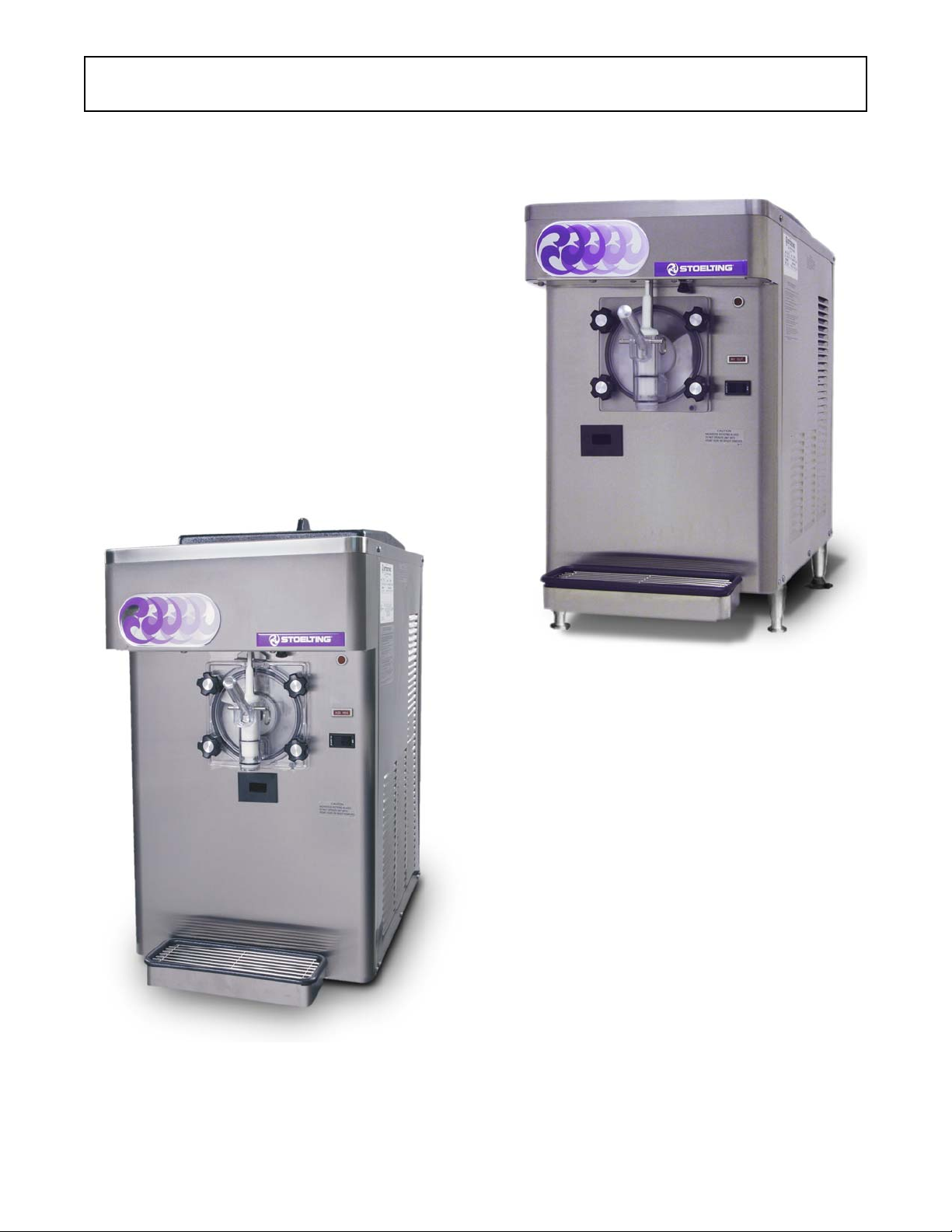
1.1 DESCRIPTION
The Stoelting E112-LJ /F112-LJ counter machines are
gravity fed. The machines are equipped with fully automatic
controls to provide a uniform product. This manual is
designed to help qualified service personnel and operators
with the installation, operation and maintenance of the
Stoelting E112-LJ /F112-LJ gravity machines.
Figure 1-1 Model F112-LJ
Figure 1-1 Model E112-LJ
1
Page 8
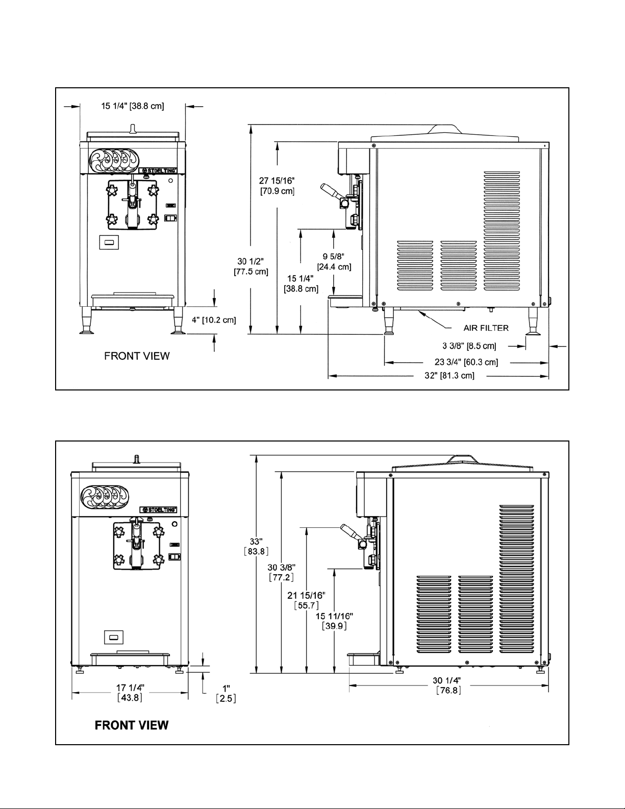
1.2 SPECIFICATIONS
E112
F112
Figure 1-2 Specifications
2
Page 9

1.2 SPECIFICATIONS - CONTINUED
Model E112 Model F112
Dimensions Machine with crate Machine with crate
widt h 15-1/4'' ( 38, 7 c m ) 17-1/ 2 '' ( 44, 5 cm ) 17-1/4'' ( 43, 8 c m ) 29'' ( 73,7 cm)
heigh t 30-1/2'' ( 77, 5 cm) 35'' (88,9 cm ) 33'' (83,8 cm) 44'' (111,8 cm )
depth 32'' (81,3 cm ) 36- 1/ 2'' (92,7 cm) 30-1/4'' ( 76, 8 cm ) 39'' (99, 1 cm )
Weight
Electrical
ru nn in g amps
con n ect ion t ype
I n ternational Option
Compressor
Drive Mot or
Air Flow
Plumbi ng Fi t tings
Hopper Volum e
Freezing Cyli nder
Volume
Production
Capacity
205 lbs (92,9 kg) 215 lbs (97, 5 kg) 288 lbs (130,6 kg) 315 lbs (142,8 kg)
1 Phase, 115 VAC, 60Hz 1 Phase, 208-240 VAC, 60Hz
approx imat el y 16A approx imat ely 10A
NEM A5- 20P po w er co r d pr ovided N EM A6- 15P power cor d p r ovided
1 Ph ase, 220-240 VAC, 50Hz 1 Phase, 220-240 VAC, 50Hz
6,000 Btu/h r 8,600 Btu/h r
1/3 h p 3/4 h p
Air cooled units require 3" (7,6 cm) air
space on both s ides or 4"
(10, 2 c m ) air spac e in ba ck
Air cooled units requ ire 6" (15,24 cm )
air spac e on bot h sides
for side-by-side in st al l a t ion
N/A
Water c ool ed un its require 3/8" N.P.T.
wat er and drain f itt in gs.
3.625 gallon ( 13, 73 l it ers ) 5.375 gallon ( 20, 35 l it ers )
1.25 gall on (5 qu art ) , 4, 73 lit ers 2.125 gall on ( 8. 5 qu ar t ), 8,04 liters
18 GPH ( 68,15 l iter s) 24 GPH ( 90,87 l iter s)
3
Page 10

4
Page 11

SECTION 2
INSTALLATION INSTRUCTIONS
2.1 SAFETY PRECAUTIONS
Do not attempt to operate the machine until the safety
precautions and operating instructions in this manual are
read completely and are thoroughly understood.
Take notice of all warning labels on the machine. The
labels have been put there to help maintain a safe working
environment. The labels have been designed to withstand
washing and cleaning. All labels must remain legible for
the life of the machine. Labels should be checked periodically to be sure they can be recognized as warning labels.
If danger, warning or caution labels are needed, indicate
the part number, type of label, location of label, and
quantity required along with your address and mail to:
STOELTING
A TTENTION: Customer Service
502 Hwy . 67
Kiel, Wisconsin 53042
Figure 2-2 Space and Ventilation Requirements
E. Correct ventilation is required. The E112-LJ requires
3” clearance on both sides. If the machine is placed
side-by-side next to other equipment, there needs
to be at lease 4” clearance at the back of the
machine. The air-cooled F112-LJ requires 6”
clearance on both sides for proper air flow.
2.2 SHIPMENT AND TRANSIT
The machine has been assembled, operated and inspected at the factory. Upon arrival at the final destination,
the entire machine must be checked for any damage
which may have occurred during transit.
With the method of packaging used, the machine should
arrive in excellent condition. THE CARRIER IS RESPONSIBLE FOR ALL DAMAGE IN TRANSIT, WHETHER
VISIBLE OR CONCEALED. Do not pay the freight bill until
the machine has been checked for damage. Have the
carrier note any visible damage on the freight bill. If
concealed damage and/or shortage is found later, advise
the carrier within 10 days and request inspection. The
customer must place claim for damages and/or shortages
in shipment with the carrier. Stoelting cannot make any
claims against the carrier.
2.3 MACHINE INSTALLATION
Installation of the machine involves moving the machine
close to its permanent location, removing all crating,
setting in place, assembling parts, and cleaning.
A. Uncrate the machine.
B. Determine the location of the machine. The location
must be able to hold 350 lbs.
C. Accurate leveling is necessary for correct drainage
of machine barrel and to insure correct overrun.
Place a bubble level on top of the machine at each
corner to check for level condition. If adjustment
is necessary, level the machine by turning the
bottom part of each leg in or out.
D. The F112-LJ has a base gasket that must be
installed. Separate the gasket and install it with the
seam to the back. Make sure the angled side of the
gasket is facing up.
CAUTION
Failure to provide adequate ventilation will void warranty .
F. Connect the drip tray bracket by loosening the two
screws at the front of the machine. Install the
bracket so that it rests on the nylon washer
between the two metal washers. Tighten the screws.
Figure 2-3 Drip Tray Bracket
G. Place the CLEAN-ON-OFF switch in the OFF
position.
5
Page 12

WARNING
Do not alter or deform electrical plug in any way.
Altering the plug to fit into an outlet of different configuration may cause fire, risk of electrical shock,
product damage and will void warranty .
H. Connect the power cord to the proper power
supply. The plug on the E112 is designed for
115VAC / 20 amp duty and the plug on the F112 is
designed for 208-240VAC / 15 amp duty. Check
the nameplate on your machine for proper supply.
The unit must be connected to a properly grounded
receptacle. The electrical cord furnished as part of
the machine has a three prong grounding type
plug. The use of an extension cord is not
recommended, if necessary use one with a size 12
gauge or heavier with ground wire. Do not use an
adapter to get around grounding requirement.
2.4 AUTO FILL PUMP INSTALLATION
The auto fill pump is powered by water and has a fixed orifice
that delivers water and syrup to the machine at an exact
ratio. The auto fill kit is designed for use with Bag In Box
(BIB) concentrated syrup.
Follow these instructions to properly install the brix pump
A. Route the clear tubing with the BIB connector to
the BIB. If there is excess tubing, trim it and
reconnect it to the BIB connector.
B. Route the water line tubing to the shutoff valve of the
water supply. Trim excess tubing and connect it to
the shutoff valve.
C. Route the water line and syrup line tubing (3/8”
braided tubing) from the pump to the machine.
water inlet
from shutoff
valve
syrup inlet
from BIB
Figure 2-5 Top View of Pump
D. Route the water line tubing to the tube exiting the
rear panel. Trim excess tubing and connect.
E. Route the syrup line to the tubing connected to the
adapter on the hopper cover. Trim excess tubing
and connect.
F. Check that the clear tubing coming out of the rear
panel is connected to the plug in the hopper cover.
If not, connect it using a clamp in the kit.
G. Check that all tubing connections are properly
clamped, fittings are tightened and the tubing is not
kinked.
water outlet
to machine
this side of
pump is
mounted to
the BIB shelf
syrup outlet
to machine
to
machine
water
inlet
Figure 2-4 Auto Fill Pump Tubing Layout
to
BIB
Figure 2-6 Auto Fill Pump Kit
6
Page 13

SECTION 3
INITIAL SET-UP AND OPERATION
3.1 OPERATOR’S SAFETY PRECAUTIONS
SAFE OPERATION IS NO ACCIDENT; observe these
rules:
A. Know the machine. Read and understand the
Operating Instructions.
B. Notice all warning labels on the machine.
C. Wear proper clothing. Avoid loose fitting garments,
and remove watches, rings or jewelry that could
cause a serious accident.
D. Maintain a clean work area. Avoid accidents by
cleaning up the area and keeping it clean.
E. Stay alert at all times. Know which switch, push
button or control you are about to use and what
effect it is going to have.
F. Disconnect electrical cord for maintenance. Never
attempt to repair or perform maintenance on the
machine until the main electrical power has been
disconnected.
G. Do not operate under unsafe operating conditions.
Never operate the machine if unusual or excessive
noise or vibration occurs.
3.2 OPERATING CONTROLS AND
INDICATORS
Before operating the machine, it is required that the
operator know the function of each operating control. Refer
WARNING
High voltage will shock, burn or cause death. The
OFF-ON switch must be placed in the OFF position
prior to disassembling for cleaning or servicing. Do
not operate machine with cabinet panels removed.
to Figure 3-1 for the location of the operating controls on the
machine.
A. Spigot Switch
The spigot switch will automatically start the auger
drive and refrigeration systems when the spigot is
opened to dispense product. When the spigot is
closed, the drive motor and compressor will remain
on until the product in the freezing cylinder reaches
the proper consistency..
Consistency
Adjustment
Screw
Diagnostic
Light
Add Mix
Indicator
Clean/Off/On
Switch
Figure 3-1 Controls
7
Page 14

B. CLEAN-OFF-ON Switch
The CLEAN-OFF-ON switch is used to supply
power to the control circuit. When the switch is in
the OFF (middle) position, power will not be
supplied to the control board or refrigeration
system. When the switch is in the ON position, the
machine will operate in the freezing mode. When
the switch is in the CLEAN position, all refrigeration
will stop and the auger will start rotating.
C. ADD MIX Light
The ADD MIX light will flash to alert the operator
to a low mix condition. It does so by monitoring the
mix level in the hopper. If the ADD MIX light is
flashing, check the auto fill system to determine
the issue. Refer to the troubleshooting section for
details
D. Diagnostic Light
The Diagnostic Light will remain lit for defrost
mode. It will flash if an error occurs. The light will
flash once if there is a compressor error. There will
be two quick flashes if there is an auger error. And
there will be three quick flashes if the machine is
left in clean mode for more than 20 minutes. Refer
to the troubleshooting section for details.
E. Consistency Adjustment Screw
The Consistency Adjustment Screw increases or
decreases product consistency. A tension spring
is connected to the screw and changes the amount
of torque needed to complete a refrigeration cycle.
Turn the knob clockwise to increase consistency
or counterclockwise to decrease consistency.
F. Front Door Safety Switch
The front door safety switch prevents the auger
from turning when the front door is removed. The
switch is open when the door is not in place and
closed when the door is properly installed.
G. Hopper Probes
The mix level in the hopper is controlled by two
probes. When mix in the hopper gets below the
long probe, the solenoid opens and the hopper fills.
When the mix level reaches the short probe, the
solenoid closes.
3.3 REMOVING MIX FROM MACHINE
To remove the mix from the machine, refer to the following
steps:
A. Wash, rinse, dry and sanitize hands before starting.
B. Turn the water line lever to the Off position.
C. Place the Clean/Off/On switch to Clean and drain
the mix from the freezer into a utility bucket and
turn off the machine. Discard mix into the second
compartment of a 3-compartment sink.
D. Fill the hopper with 2 gallons of clean, cold water
using the clean white utility bucket.
E. Place the Clean/Off/On switch to Clean. Run the
machine in Clean mode for approximately 5
minutes. Continue to the next step while the
machine is cleaning.
F. Prepare Stera-Sheen Green Label Sanitizer
according to manufacturer’s instructions to provide
a 100ppm strength solution. In the blue cleaner/
sanitizer bucket, mix 1 packet of sanitizer and 2
gallons of cold water. Check the chlorine content
with a test strip to ensure 100ppm strength.
G. After 5 minutes, drain the water from the machine
into the red utility bucket and discard the water.
NOTE
If the water does not drain clear, repeat the step s.
H. Place the Clean/Off/On switch Off.
I. Fill the hopper with the 2 gallons of sanitizer
solution from the blue bucket.
J. Place the Clean/Off/On switch to Clean. Run the
machine in Clean mode for approximately 5
minutes.
K. After 5 minutes, drain the sanitizer solution from
the machine into the red utility bucket and discard
the solution.
3.4 DISASSEMBLY OF MACHINE PARTS
Inspect for worn or broken parts each time the machine is
disassembled. Replace any worn or broken parts to ensure
safety to both the operator and the customer and to
maintain good machine performance and a quality product.
Frequency of cleaning must comply with the local health
regulations.
To disassemble the machine, refer to the following steps:
CAUTION
Hazardous Moving Parts.
Revolving auger shaft can grab and cause injury.
Place the switch in the OFF (middle) position before disassembling for cleaning or servicing.
8
Page 15

Figure 3-2 Remove Spigot Pin
A. Pull out the spigot pin by its ring. Remove the
spigot handle.
NOTE
Place all parts into the lemonade parts basket immediately after removing from the machine. Place
small parts onto the small parts rod in the basket.
B. Remove front door by turning the circular knobs
and then pulling door off the studs.
NOTE
When removing front door, entire door and stator
assembly will come out as well.
C. Remove the torque rod from the stator assembly.
D. Remove the quad ring from the groove in front door.
E. Remove the stator bar. Remove the small white
bushing.
Figure 3-4 Removing O-Ring
F. Remove the o-rings at the front and back of the
stator bar by first wiping off the lubricant using a
clean paper towel. Then squeeze the o-ring upward
with a dry cloth. When a loop is formed, roll the o-
ring out of the groove.
G. Remove the auger support bushing.
H. Turn the spigot body until the ice breaker bar can
be removed. Remove breaker bar.
I. Remove the spigot body from the front door.
J. Remove the o-rings (2) from the spigot.
K. Remove the auger assembly from the freezing
cylinder and remove the auger blade. Remove the
rear seal and o-ring from the auger.
L. Remove the drain tray, drip tray and drip tray grid.
M. Remove the hopper cover and disconnect the auto
fill adapter from the cover by pulling out the retaining
clip.
Figure 3-3 Spigot and Ice Breaker Bar Removal
3.5 CLEANING AND SANITIZING THE
MACHINE PARTS
Place all loose parts in a pan or container and take to the
wash sink for cleaning. Local and state health codes dictate
the procedure required. Some health codes require a foursink process (pre-wash, wash, rinse, sanitize, and air-dry),
while other codes require a three-sink process (without the
pre-wash step). The following procedures are a general
guideline only. Consult your local and state health codes for
procedures required in your location.
A. Set up a 3-compartment sink with wash, rinse and
sanitize compartments. Use only Stera Sheen
Green Label or Kay-5 Green. Prepare sanitizer
according to manufacturer’s instructions to provide
a 100ppm strength solution. Set aside a small
amount of sanitizer
B. Clean all parts using brushes provided.
C. After cleaning, remove the parts and let air dry.
9
Page 16

Figure 3-5 Cleaning Freezing Cylinder
D. Sanitize the hopper and freezing cylinder with
sanitizer. Be sure to clean the rear seal surfaces
inside the freezing cylinder.
E. Wipe down the outside of the machine and table
with a yellow sanitized towel.
3.6 ASSEMBLY OF MACHINE
CAUTION
Do not allow sanitizer to remain in contact with stainless steel parts for prolonged periods. Prolonged
contact of sanitizer with machine may cause corrosion of stainless steel parts.
To assemble the machine parts, refer to the following steps:
NOTE
Petrol Gel sanitary lubricant or equivalent must be
used when lubrication of parts is specified.
NOTE
The United States Department of Agriculture and
the Food and Drug Administration require that lubricants used on food processing equipment be certified for this use. Use lubricants only in accordance
with the manufacturer’s instructions.
A. Wash, rinse, dry and sanitize hands before starting.
B. Place the rear seal o-ring onto the auger and apply
a thin film of Petrol-Gel to the o-ring.
C. Assemble the rear seal onto the auger with the
large end of the seal to the rear. Lubricate the hex
end of the auger with a small amount of spline
lubricant.
D. Install the plastic auger blade onto the auger. Push
the auger into the freezing cylinder and rotate it
slowly until the auger engages the drive shaft.
E. Assemble the o-rings onto the spigot body and
apply a thin film of Petrol-Gel onto the o-rings.
F. Insert the spigot body into the front door.
NOTE
When inserting the spigot body, press the o-rings
against the spigot to prevent damage.
T orque
Rod
Auger
Support
Bushing
Stator Bar
Front O-Ring
figure 3-6 Door and Stator Assembly
Stator Bar
Bushing
Stator Bar
10
Stator Bar
Rear O-Ring
Quad
Ring
Page 17

G. Turn the spigot body until the ice breaker bar can
be inserted. Insert the ice breaker bar and rotate
spigot body 90°.
H. Apply Petrol-Gel to the inside and outside of the
front auger support bushing. Install the bushing
onto the front door so the beveled edge of the
bushing is against the door.
I. Install the large quad ring into the groove in the front
door.
J. Install the o-rings at the front and back of the stator
bar. Apply a thin film of Petrol-Gel onto the o-rings.
Install the small white bushing to the stator bar.
K. Insert the stator bar into the front door and insert
the torque rod through the hole in the stator bar.
L. Install the front door onto the freezer. Install the
knobs onto the studs.
NOTE
When installing the front door , the torque rod must
be placed in the center notch of the torque actuator
arm.
M. Insert the spigot handle so the hole lines up and
insert the spigot pin.
N. Install the drain tray, drip tray and drip tray grid.
3.7 SANITIZING
Sanitizing must be done after the machine is cleaned and
just before the hopper is filled with mix. Sanitizing the night
before is not effective. However, you should always clean
the machine and parts after each use.
The United States Department of Agriculture and the Food
and Drug Administration require that all cleaning and
sanitizing solutions used with food processing equipment
be certified for this use.
When sanitizing the machine, refer to local sanitary regulations for applicable codes and recommended sanitizing
products and procedures. The frequency of sanitizing must
comply with local health regulations.
Mix sanitizer according to manufacturer’s instructions to
provide a 100 parts per million (ppm) strength solution and
check the solution with chlorine test strips. Mix sanitizer in
quantities of no less than 2 gallons (7.5 liters) of 90° to
110°F (32° to 43°C) water. Allow sanitizer to contact the
surfaces to be sanitized for 5 minutes. Any sanitizer must
be used only in accordance with the manufacturer’s instructions.
In general, sanitizing may be conducted as follows:
A. Prepare Stera-Sheen Green Label Sanitizer
according to manufacturer’s instructions to provide
a 100ppm strength solution. In the blue cleaner/
sanitizer bucket, mix 1 packet of sanitizer and 2
gallons of cold water. Check the chlorine content
with a test strip to ensure 100ppm strength.
B. Pour the sanitizing solution into the hopper.
C. Place the Clean/Off/On switch to Clean.
D. Use a sanitized barrel brush to sanitize the hopper
sides and hopper cover with the sanitizer solution
in the hopper.
E. After 5 minutes, drain the sanitizer solution from
the machine into the red utility bucket and discard
the solution. Leave a small amount of sanitizer
solution in the freezing cylinder.
F. Place the Clean/Off/On switch Off.
G. Collect the remaining sanitizer in a clean cup and
check the chlorine content with a test strip. If the
chlorine content is less than 100ppm, repeat the
sanitizing procedure. If the test strip does not read
100ppm after the second test, repeat the
disassembly, cleaning and sanitizing procedures.
H. Connect the auto fill adapter to the hopper cover
with the retaining clip and place the hopper cover
onto the hopper.
I. Turn the water line lever to the On position.
J. Turn the Clean/Off/On switch On. Open the spigot
to drain out any remaining sanitizer into the red
utility bucket. Close the spigot when mix begins
coming out.
3.8 FREEZE DOWN AND OPERATION
This section covers the recommended operating procedures for the safe operation of the machine.
A. After the freezing cylinder is filled, product will be
ready to serve in 8 to 12 minutes.
B. To dispense, pull the spigot handle down to open
the spigot.
CAUTION
Do not allow sanitizer to remain in contact with stainless steel parts for prolonged periods. Prolonged
contact of sanitizer with machine may cause corrosion of stainless steel parts.
11
Page 18

C. The machine is designed to dispense the product
at a reasonable draw rate. If the machine is
overdrawn, the result is a wet product or a product
that will not dispense at all. If this should occur,
allow the machine to run for approximately 30
seconds before dispensing additional product.
D. Do not operate the machine when the ADD MIX
light is on. Immediately check if the auto fill system
is operating properly.
NOTE
After 3 hours if the spigot is not opened, the machine will go into defrost mode. During this time, the
diagnostic light will be lit and the auger will run for 90
seconds every 7 minutes. Defrost mode maintains
consistency in the product and prevents large ice
crystals from forming. T o end defrost mode, turn the
Clean/Off/On switch Off then back On. Defrost mode
will also end if the spigot is opened.
3.9 MIX INFORMATION
Mix can vary considerably from one manufacturer to another. Differences in the quantity and quality of ingredients
have a direct bearing on the finished frozen product. A
change in machine performance that cannot be explained
by a technical problem may be related to the mix.
Proper product serving temperature varies from one
manufacturer’s mix to another. Stackable slush mixes
provide satisfactory product from 24° to 28°F (-4° to -2°C).
When checking the temperature, stir the thermometer in
the frozen product to obtain an accurate reading.
D. QUARTERLY
Air Cooled
The air-cooled condenser is a copper tube and aluminum fin
type. Condensing is totally dependent upon airflow. A
plugged condenser filter, condenser, or restrictions in the
louvered panel will restrict airflow. This will lower the
capacity of the system and damage the compressor.
The condenser must be kept clean of dirt and grease. The
F112 must have a minimum of 6” (15.2 cm) of ventilation on
the right and left sides of the unit for free flow of air. The E112
must have 3” (7.6 cm) of ventilation. Make sure the machine
is not pulling over 100° F (37° C) air from other equipment
in the area.
The condenser and condenser filter require periodic cleaning. To clean, refer to the following procedures.
E112 Air Cooled Condenser Cleaning
A. Unscrew the knob located on the underside of the
machine towards the front (Fig. 3-7).
B. Remove the filter bracket and remove the filter.
C. Visually inspect the condenser filter for dirt.
D. If the filter is dirty, vacuum or brush clean, rinse with
clean water and allow to dry before replacing on the
machine.
NOTE
If the condenser is not kept clean, refrigeration efficiency will be lost.
3.10 ROUTINE CLEANING
To remove spilled or dried mix from the machine exterior,
wash in the direction of the finish with warm soapy water
and wipe dry. Do not use highly abrasive materials as they
will mar the finish.
3.11 PREVENTIVE MAINTENANCE
Stoelting recommends that a maintenance schedule be
followed to keep the machine clean and operating properly.
B. DAILY
1. The exterior should be kept clean at all times to
preserve the luster of the stainless steel. A mild
alkaline cleaner is recommended. Use a soft cloth
or sponge to apply the cleaner.
C. WEEKLY
1. Check o-rings and rear seal for excessive wear and
replace if necessary.
2. Remove the drip tray by gently lifting up to disengage
from the support and pulling out. Clean behind the
drip tray and front of the machine with a soap
solution.
Figure 3-7 E112 Condenser Filter Removal
12
Page 19

Figure 3-8 F112 Condenser Filter Removal
F112 Air Cooled Condenser Cleaning
A. Remove the Phillips head screws from the bottom
of the left side panel, and then slide the panel down
and out.
B. To remove the condenser filter, grasp the top and
pull off. Visually inspect for dirt. If the filter is dirty,
shake or brush excess dirt off the filter and wash in
warm, soapy water. Once the filter is clean rinse
thoroughly in warm, clear water and shake dry,
taking care not to damage the filter in any way (Fig.
3-8).
C. Visually inspect the condenser for dirt by shining
a light through the coil from the back (inside) of the
condenser.
D. If the condenser is dirty, place a wet towel over the
front (outside) of the condenser.
E. Using a vacuum, carefully clean the condenser coil
from the inside and outside of the machine. A stiff
bristled brush may help in releasing debris from
between the condenser coils.
Water Cooled (F112 only)
The water-cooled condenser is a tube and shell type. The
condenser needs a cool, clean supply of water to properly
cool the machine, inlet and discharge lines must be 3/8” I.D.
minimum. Make sure the machine is receiving an unrestricted supply of cold, clean water.
E. SEMI-ANNUALLY
1. Disconnect the machine from the power source.
2. Check drive belt for proper tension. Push belt in
with one finger, belt should deflect about 3/8".
3. Lubricate condenser fan motor with S.A.E. 20
weight oil. Three to six drops are required.
4. Sanitize the autofill system following the steps
below:
AUTO FILL SANITIZING
A. If necessary, disassemble, clean and sanitize the
machine.
NOTE
If the machine does not require cleaning and sanitizing, turn it off and dispense enough product so
that the mix level in the hopper is below the long
probe. If the mix level is above the long probe, the
solenoid will not activate and the pump will not operate.
B. Prepare Stera-Sheen Green Label Sanitizer
according to manufacturer’s instructions to provide
a 100ppm strength solution. In the blue cleaner/
sanitizer bucket, mix 1 packet of sanitizer and 2
gallons of cold water. Check the chlorine content
with a test strip to ensure 100ppm strength.
C. Cut an adapter from an empty bag of syrup.
Connect the adapter to the BIB connector of the
syrup line. Put the BIB connector into the bucket
of sanitizer.
NOTE
If you do not have an emtpy bag of syrup, remove
the plug from the top of the BIB connector. Do not
lose the plug; it is needed for proper operation of the
BIB.
D. Hold the hopper cover over a bucket and set the
machine to clean. The solenoid will activate and
the brix pump will pump sanitizer into the bucket.
NOTE
The solenoid will only activate when there is not any
liquid touching the longer mix probe in the hopper.
E. After all the sanitizer has run through the pump,
turn the machine off.
F. Disconnect the bag adapter from the BIB connector
(or reinsert the plug into the connector). Connect
the BIB connector to the syrup BIB.
G. Set the machine to clean and hold the hopper cover
over a bucket. This will flush the sanitizer out of the
pump and tubing. When pure syrup comes out of
the tubing, turn the machine off.
H. The machineis now ready to operate. Place the
hopper cover on the hopper and turn the machine
on.
13
Page 20

3.12 EXTENDED STORAGE
Refer to the following steps for storage of the machine over
any long period of shutdown time:
A. Follow the cleaning and sanitizing procedures for
the machine and follow the semi-annual instructions
to sanitize the auto fill system.
B. Place the CLEAN-OFF-ON switch in the OFF
(middle) position.
C. Disconnect (unplug) from the electrical supply
source.
D. Clean thoroughly with a warm water detergent all
parts that come in contact with the mix. Rinse in
clean water and dry parts. Do not sanitize.
NOTE
Do not let the cleaning solution stand in the hopper
or in the freezing cylinder during the shutdown period.
E. Remove, disassemble and clean the front door,
mix inlet regulator and auger parts.
F. In a water cooled machine, disconnect water lines
and drain water. With a flathead screwdriver, hold
the water valve open and use compressed air to
clear the lines of any remaining water.
14
Page 21

SECTION 4
TROUBLESHOOTING
4.1 LIGHT INDICATORS
The machine has two lights that will alert the user if a problem occurs: an ADD MIX light and a Diagnostic Light.
The ADD MIX light will flash to alert the operator to a low mix condition. It does so by monitoring the mix level in the
hopper. When the ADD MIX light is flashing, refill hopper immediately.
The Diagnostic Light will flash if an error occurs. Refer to the chart below for details.
Indication On One Blink Two Blinks Three Blinks
Conditions
Self
Correction
Defrost Mode
N/A N/A
Torque is not
met after 20
minutes
Drive c urrent i s not s ensed
The machine at t em pt s to sense drive
current with a 3 sec ond pre-s t i r. If current
is sensed, the machine will return to
normal operati on. If c urrent is not s ensed,
the m ac hi ne wil l wait 7 minut es and try t o
sense current with another 3 second pre-
stir. After the third attempt, the
compressor wil l run o n timers.
Mac hi ne left i n c l ean
mode for over 20
minutes
N/A
Every 7 m i nut es
Operation
Corrective
Action
the auger will
run for 90
seconds.
End Defrost
Mode by t urning
Clean/Off/On
switch OFF
then t urning i t
back ON.
Opening the
spi got wil l al so
end Defrost
Mode.
4.2 TROUBLESHOOTING
PROBLEM
1 P ower t o m achine is off. 1 S uppl y power to m ac h ine .
Machine does not
run.
Machine w ill not
shut off.
Product is too firm.
2 Blown fuse or tripped circuit. 2 Replace or reset.
3 Freeze-up (auger will not turn). 3 Turn Clean/Off/O n s wi t ch Off for 15 m inu t es,
4 Front door not in pl ace. 4 A ssem bl e front doo r in pl ace.
1 Drive belt fail ure. 1 Repla c e dri ve belt.
2 Cons i stenc y tem perature set ting is too
firm.
3 Refrigerat i on probl em . 3 Chec k syst e m . (Call di stribu t or for s ervice)
1 Cons i stenc y tem perature set ting is too
firm.
Timers or until
torque s wi t ch
remains closed
for 3 seconds.
Cont act Service
Technician
POSSI BL E CAUSE REMEDY
Contac t Servi ce Technici an
Timers Off
then restart.
2 Turn Consi s tency Adjustm ent knob counter-
clockwise.
1 Turn Consi s tency Adjustm ent knob counter-
clockwise.
15
Turn Clean/Off/On
switch OFF then turn
it back ON.
Page 22

4.2 TROUBLESHOOTING - CONTINUED
PROBLEM
Product is too thin.
Product does not
dispense.
Drive be l t slipping
or sque aling.
Rear auger seal
lea ks.
Front door le aks.
POSSI BL E CAUSE REMEDY
1 No vent space for free flow of cooli ng
air.
2 Condenser is di rty. 2 Clean . (S ee Sect i on 3)
3 Cons i stency s e t t i n g t oo soft. 3 Turn Consis t ency A dj us tment knob cl ockwise.
4 A uger i s ass em ble d incorrectly . 4 Rem ove mix , clean, reassem bl e, sani t i ze and
5 A ut o F i l l P um p not operati ng. 5 See A ut o F i l l Troubles hooting s ec tion.
6 Refrigerat i on probl em . 6 Chec k syst e m . (Cal l distri but o r for se rvice)
1 No mi x in hopper. 1 S ee A uto Fil l Troubles hooting s ec tion.
2 Drive motor overload tripped . 2 W ai t for aut om atic reset. (If c o ndi t i on
3 Drive belt fail ure. 3 Repla c e dri ve belt.
4 Freeze-up (Auger will not t u rn). 4 Turn Clean/O ff/On switch Off for 15 minutes,
1 Worn drive bel t . 1 Repla c e dri ve belt.
2 Freeze-up (Auger will not t u rn). 2 Turn Clean/O ff/On switch Off for 15 minutes,
3 Not t ensioned properly. 3 A dj ust bel t t en sion
1 Outside surface of rear auger seal is
lubricated.
2 Rear s eal m i ssi ng or dam aged. 2 Check or repl ace.
3 S eal o-ri ng m i s sing, dam aged or
installed incorrec t ly .
4 Worn or scratc hed auger s haft . 4 Repl ace auger sh aft.
1 Front door knobs are loos e. 1 Tight en k no bs .
2 S pi got parts are not lubric ated. 2 See S ection 3.
3 Chippe d or worn s pi got o-rings . 3 Repla ce o-rings .
4 O-rin gs or s pi got ins talle d wrong. 4 Remove spigot and check o-ring.
5 Inner s pig ot hol e i n front door ni c ked or
scratched.
1 A m i ni m um of 6" of air s pace on both sides (t he
E112 requi res 3"). (S ee S ecti on 2)
freeze down.
continues , call distri but o r for service.)
then restart .
then restart .
1 Clean lubri cant from outsi de of rear sea l,
lubricate i ns ide of seal and rei nstall .
3 Chec k. or repl ace.
5 Repla c e front door.
4.3 TROUBLESHOOTING - AUTO FILL SYSTEM
1 Low wat er pressure. 1 V eri fy t hat there is adequate wat er pressure at
Pump do e s not
operate.
Syrup
conce ntration
incorrect
2 Res t ri cti on or pl ugged auto fill system. 2 Flush and sanitize the pump and tubing.
3 E m pt y BIB 3 Replace BIB
1 B IB connector is not connec t ed to the
BIB prope rly.
2 Leak at t he c on nectio ns or i n t he
tubing.
3 A i r in the BIB syrup contain er. 3 Rem ove the air from th e B IB syrup contai ner.
4 P ump is clogged wi th debris or
particulates.
the i nl et fitti ng (30-50 ps i ).
1 Chec k connecti on and reconnect if necessary .
2 Look for leaks at the c onnecti ons and bubbles
in t he t ubi ng. Tighten c l am ps and replac e
tubing if necess ary .
4 Rem ove syrup valves and i ns pe c t for debris or
improp er clos i ng that woul d i nterfere with
operation.
16
Page 23

5.1 DECALS AND LUBRICATION
Part Description E112-LJ F112-LJ
208135 Brush - 4" X 8" X 16" (Barrel) 1 1
208380 Brush - 1/4" X 3" X 14" 1 1
208401 Brush - 1" X 3" X 10" 1 1
236054 Cleaning Card - Auto Fill Pump Kit 1 1
324105 Decal - Caution Electrical Shock 1 1
324106 Decal - Caution Electrical Wiring Materials 1 1
324107 Decal - Caution Hazardous Moving Parts 1 1
324141 Decal - Caution Rotating Blades 1 1
324208 Decal - Attention Refrigerant Leak Check 1 1
324393 Decal - Stoelting Swirl Logo 1 1
324509 Decal - Cleaning Instructions 1 1
324548 Decal - Adequate Ventilation 6" 1
324566 Decal - Wired According To 1 1
324584 Decal - Adequate Ventilation 3" 1
324686 Decal - Danger Automatic Start 1 1
324804 Decal - Domed Stoelting Swirl (Header Panel) 1 1
324852 Decal - Clean Condenser Filter 1
324865 Decal - Standby Light 1 1
508048 Lubricant - Spline (2 oz Squeeze Tube) 1 1
508135 Petrol Gel - 4 oz Tube 1 1
SECTION 5
REPLACEMENT PARTS
Quantity
17
Page 24

5.2 AUGER SHAFT AND FACEPLATE PARTS
624678
666786
F112 - 2183751
E112 - 2183854
624515
630053
2183739
E112 - 2187600
F112 - 2187941
2183099
624644
624645
2183444
570196
624545
2187188
E112 - 2202181
F112 - 2202068
625310
2183447
336551
482019
18
Page 25

5.2 AUGER SHAFT AND FACEPLATE PARTS - CONTINUED
Quantity
Part Description E112-LJ F112-LJ
336551 Door - Front 1 1
482019 Knob - Front Door (Black) 4 4
570196 Pin - Cotterless Clevis (Front Door) 1 1
624515-5 O-Ring - Stator Bar Rear (5 Pack) 1 1
624545-5 O-Ring - Stator Bar Front (5 Pack) 1 1
624644-5 O-Ring - Spigot Body (Bottom) (5 Pack) 1 1
625310 Quad-Ring - Front Door - Black 1 1
630053 Rod - Torque Actuator 1 1
666786 Seal - Rear Auger - Black 1 1
2183099 Breaker Bar - Spigot Body 1 1
2183444 Bushing - Stator Support (Rear) 1 1
2183447 Handle Only - Spigot 1 1
2183739 Spigot Body 1 1
2183751 Blade - Scraper 1
2183854 Blade - Scraper 1
2187188 Bushing - Front Auger Support 1 1
2187600 Auger Shaft 1
2187941 Auger Shaft 1
2202068 Stator Bar 1
624645-5 O-Ring - Spigot Body (Top) (5 Pack) 1 1
624678-5 O-Ring - Rear Seal - Black (5 Pack) 1 1
2202181 Stator Bar 1
19
Page 26

5.3 HOPPER PARTS
2187918
2177315
2187919
417006
744281
744254
Quantity
Part Description E112-LJ F112-LJ
396244 Gasket - Freezer Base 1
417006 Grid - Drip Tray (Metal) 1 1
624607-5 O-Ring - Mix Inlet (5 Pack) 2 2
744254 Tray - Drip 1 1
744281 Tray - Drain 1 1
2177315 Cover - Hopper 1 1
2187918 Mix Inlet Assembly 1 1
2187919 Clip - Retaining (Mix Inlet) 1 1
20
Page 27

5.4 AUTO FILL PARTS
756222
756222
756221
600930
756222
292219
616116
375645
756222
Part Description Quantity
264100 Clamp - Oetiker Stepless 25
292219 Connector - Bag In Box 1
375645 Fitting - 3/8” x 3/8” 1
538463 Nut 2
600930 Pump - Brix 1
616116 Water Regulator 1
644359 Screw - 10-32 x 1/2” 2
739126 Tie Wrap - 15” 10
739127 Tie Wrap - 7” 2
756221 Tubing - 3/8” Clear 3’
756222 Tubing - 3/8” Braided 40 ’
21
Page 28

22
Page 29

LJS IceFlow WARRANTY
F112-LJ, E112-LJ and Autofill Mix Brix Pump System
1. Scope:
Stoelting LLC warrants to the first user (the “Buyer”) that the evaporator assembly, compressor, drive
motor and speed reducer (if applicable) of Stoelting F112–LJ, E112-LJ and Autofill mix brix pump
equipment will be free from defects in materials and workmanship under normal use and proper
maintenance appearing within five (5) years and that all other components of such equipment
manufactured by Stoelting will be free from defects in material and workmanship under normal use
and proper maintenance appearing within twenty-four (24) months after the date that such equipment
is originally installed.
2. Disclaimer of Other Warranties
THIS WARRANTY IS EXCLUSIVE; AND STOELTING HEREBY DISCLAIMS ANY
IMPLIED WARRANTY OF MERCHANTABILITY OR FITNESS FOR PARTICULAR
PURPOSE.
3. Remedies:
Stoelting’s sole obligations, and Buyer’s sole remedies, for any breach of this warranty shall be the
repair or (at Stoelting’s option) replacement of the affected component at Stoelting’s plant in Kiel,
Wisconsin, or (again, at Stoelting’s option) refund of the purchase price of the affected equipment,
and, during the first twenty-four (24)
equipment) of the warranty period, deinstallation/reinstallation of the affected component from/into the
equipment. Those obligations/remedies are subject to the conditions that Buyer (a) signs and returns
to Stoelting, upon installation, the Warranty Registration Card for the affected equipment, (b) gives
Stoelting prompt written notice of any claimed breach of warranty within the applicable warranty
period, and (c) delivers the affected equipment to Stoelting or its designated service location, in its
original packaging/crating, also within that period. Buyer shall bear the cost and risk of shipping to and
from Stoelting’s plant or designated service location.
4. Exclusions and Limitations:
This warranty does not extend to parts, sometimes called “wear parts”, which are generally expected
to deteriorate and to require replacement as equipment is used, including as examples but not
intended to be limited to o-rings, hoses, seals and drive belts. All such parts are sold
Further, Stoelting shall not be responsible to provide any remedy under this warranty with respect to
any component that fails by reason of negligence, abnormal use, misuse or abuse, use with parts or
equipment not manufactured or supplied by Stoelting, or damage in transit.
THE REMEDIES SET FORTH IN THIS WARRANTY SHALL BE THE SOLE LIABILITY
STOELTING AND THE EXCLUSIVE REMEDY OF BUYER WITH RESPECT TO
EQUIPMENT SUPPLIED BY STOELTING; AND IN NO EVENT SHALL STOELTING BE
LIABLE FOR ANY INCIDENTAL OR CONSEQUENTIAL DAMAGES, WHETHER FOR
BREACH OF WARRANTY OR OTHER CONTRACT BREACH, NEGLIGENCE OR
OTHER TORT, OR ON ANY STRICT LIABILITY THEORY.
:
months (first twelve (12) months for Autofill mix brix pump
AS IS.
Form 721-090, Rev, 00
Page 1 of 1
 Loading...