

Stoelting DQU411 Service Manual

A VOLLRATH® DIVISION
Model DQU411
Operator’s Manual
513687 Rev.2

Section 1: Introduction
INTRODUCTION
This manual provides basic information about the machine. Instructions and suggestions are given covering its operation
and care. This manual follows the guidance set forth in the following industry standards: ANSI Z535.6, ASTM F760-93,
ASTM F1827-13, FDA Food Code.
The illustrations and specifi cations in this manual are not binding in detail. We reserve the right to make changes to the
machine without notice, and without incurring any obligation to modify or provide new parts for machines built prior to
date of change.
DO NOT ATTEMPT to operate the machine until instructions and safety precautions in this manual are read completely
and are thoroughly understood. If problems develop or questions arise in connection with installation, operation, or servicing of the machine, contact Stoelting White Glove Service.
For warranty information, visit stoeltingfoodservice.com
MAINTENANCEPARTS TROUBLESHOOTING OPERATION
A VOLLRATH® DIVISION
stoeltingfoodservice.com
Stoelting Foodservice Equipment
502 Highway 67
Kiel, WI 53042-1600
U.S.A.
White Glove Service Network
Phone: 888.319.9549
© 2020 Stoelting
2 DQU411-I2 OPERATOR’S MANUAL 513687 REV.2

This manual is divided into the following fi ve sections:
Section 1: Introduction
INTRODUCTION
INTRODUCTION
OPERATION
MAINTENANCE
A. Parts of the Machine
B. Specifi cations
A. Empty the Freezing Cylinders - Start here if cleaning a machine with mix in it
B. Disassemble Parts - Start here if cleaning an empty machine
C. Cleaning Disassembled Parts
D. Cleaning the Machine
E. Assembling the Machine
F. Sanitizing
G. Freeze Down
H. Lubrication Points
I. Pump Hose Routing
A. Mix Pump Hose Replacement
B. Mix Pump Hose Cleaning
C. Fine Consistency Adjustment
D. Daily Procedures - Night
E. Daily Procedures Morning
MAINTENANCE PARTSTROUBLESHOOTINGOPERATION
TROUBLESHOOTING
PART S
513687 REV.2 DQU411-I2 OPERATOR’S MANUAL 3
A. Troubleshooting Flow Charts
A. Auger Shaft & Front Door Parts
B. Cab Tubing

Section 1: Introduction
A. Parts of the DQU411-I2 Machine
IntelliTec2™
INTRODUCTION
Spigot Handle
Freezing Cylinder
MAINTENANCEPARTS TROUBLESHOOTING OPERATION
Cabinet
IntelliTec2™ Touchpad
4 DQU411-I2 OPERATOR’S MANUAL 513687 REV.2
Section 1: Introduction
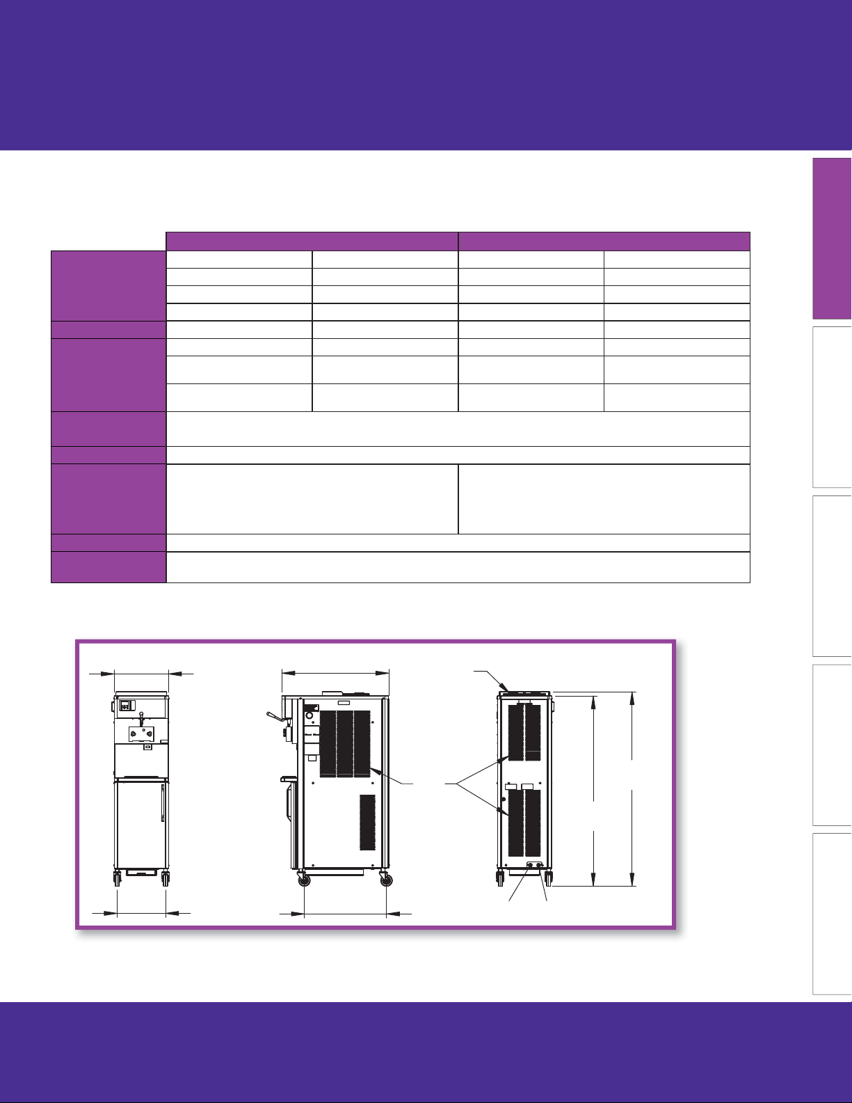
B. DQU411-I2 Specifi cations
DQU411-I2 Water Cooled DQU411-I2 Air Cooled
Dimensions Machine with crate Machine with crate
width 19-1/8’’ (48,6 cm) 34’’ (86,4 cm) 19-1/8’’ (48,6 cm) 34’’ (86,4 cm)
height 66-7/8’’ (169,9 cm) 78’’ (198,1 cm) 66-7/8’’ (169,9 cm) 78’’ (198,1 cm)
depth 37-5/8’’ (95,6 cm) 48’’ (121,9 cm) 37-5/8’’ (95,6 cm) 48’’ (121,9 cm)
Weight 450 lbs (204,1 kg) 650 lbs (294,8 kg) 450 lbs (204,1 kg) 650 lbs (294,8 kg)
Electrical 1 PH 3 PH 1 PH 3 PH
running amps
connection type
Compressor
Drive Motor 2 hp
Water cooled units require 1/2” N.P.T. water and drain
Cooling
Hopper Volume Two - 8 gallon (30,28 liters)
Freezing Cylinder
Volume
fi ttings. Maximum water pressure of 130 psi. Minimum
17A 15A 18A 16A
NEMA L6-30P NEMA L15-30P NEMA L6-30P NEMA L15-30P
15,000 Btu/hr Scroll™ Compressor
Cabinet - 1,300 Btu/hr Compressor
Air cooled units require 3” (7.6 cm) air space at the back
water fl ow rate of 3 GPM. Ideal EWT of 50°-70°F.
1.33 gallon (5,4 liters)
and sides.
INTRODUCTION
MAINTENANCE PARTSTROUBLESHOOTINGOPERATION
19 1/8"
17"
37 5/8"
28 7/8"
Air Out
Air In
Water Inlet Water Outlet
A/C
68 3/8"
W/C
66 7/8"
513687 REV.2 DQU411-I2 OPERATOR’S MANUAL 5
Section 2: Operation
A. Empty the Freezing Cylinders
A.1
Turn o freezing cylinder.
OPERATION INTRODUCTION
MAINTENANCEPARTS TROUBLESHOOTING
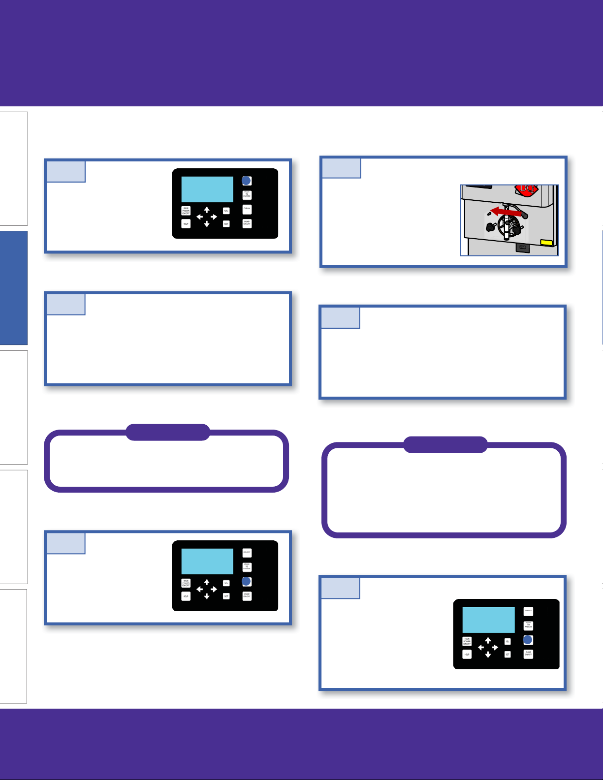
A.2
In the cab, disconnect the bag adapter and place it in
a bucket fi lled with cool tap water.
Remove the mix bag and store it in the cooler.
Optional: Fill the bucket with Stera Sheen
solution to make cleaning parts easier
after disassembly.
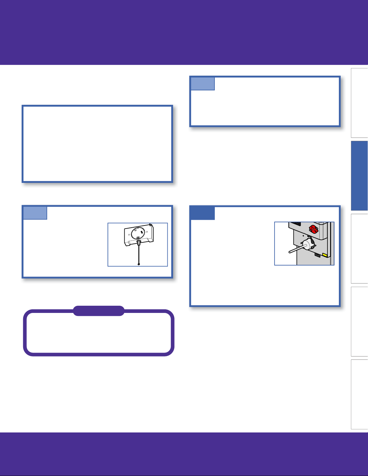
A.4
Open the spigot to drain the
product into a container until
the container is full. Empty
the container and repeat until
product has been drained
from the freezing cylinder.
A.5
Refi ll the bucket in the cab with cool tap water (or Stera
Sheen). Allow the freezing cylinder to fi ll then drain the
water into a container. Repeat until the water draining
from the freezing cylinder is clear.
NOTE
NOTE
If the “Clean Time Exceeded” warning
is displayed on the IntelliTec2™, turn
the freezing cylinder on and o again
and press the Clean button to clear the
warning.
A.3
Press the Clean button.
A.6
Remove any remaining
water from the bucket in the
cabinet.
Drain the water and press
the Clean button to stop
the auger.
6 DQU411-I2 OPERATOR’S MANUAL 513687 REV.2
A.7
Remove the bucket in the
cab and turn on the pump to
clear any remaining liquid in
the hoses.
Open the spigot to drain the
freezing cylinder.
A.8
Section 2: Operation
OPERATIONINTRODUCTION
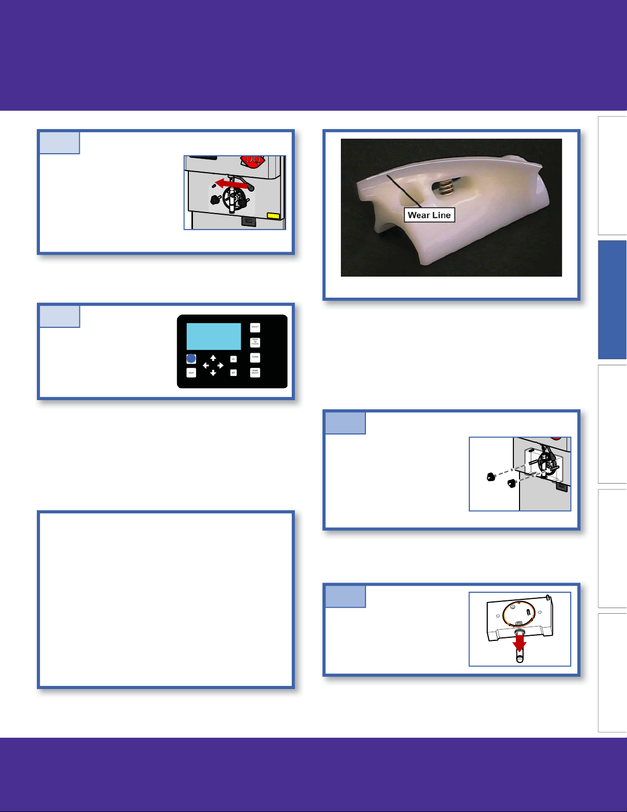
Auger Flight Wear
Press and hold the Main
Freezer Power button for
three seconds to turn o
the power.
B. Disassemble Parts
Before using the machine for the fi rst time, complete
machine disassembly, cleaning and sanitizing
procedures need to be followed. Routine cleaning
intervals and procedures must comply with the local
and state health regulations. Inspection for worn or
broken parts should be made at every disassembly
of the machine. All worn or broken parts should be
replaced to ensure safety to both the operator and the
customer and to maintain good machine performance
and a quality product. Check the wear line on the auger
fl ights on a regular basis and replace as needed.
1. Front Door Disassembly
MAINTENANCE PARTSTROUBLESHOOTING
B.1
Remove the spigot extension
or rosette cap if installed.
Unscrew the knobs on the
front door and remove the
door.
B.2
Remove the front door o-ring
and remove the spigot from
the front door.
513687 REV.2 DQU411-I2 OPERATOR’S MANUAL 7
Section 2: Operation
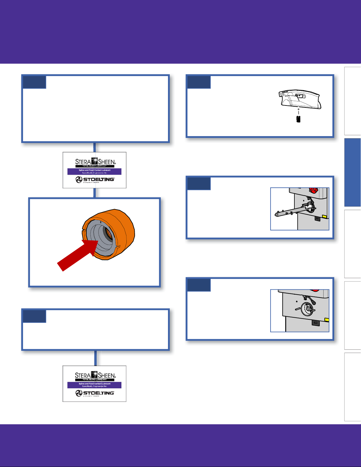
B.3
Remove the air bleed valve
from the front door.
B.4
Remove all o-rings from
parts by fi rst wiping o the
OPERATION INTRODUCTION
lubrication using a clean towel.
Then squeeze the o-ring
upward to form a loop. Roll
the o-ring out of the groove.
B.5
MAINTENANCEPARTS TROUBLESHOOTING
Remove front auger support
and bushing and remove
the auger from the freezing
cylinder. As the auger is being
pulled out, remove the plastic
fl ights with springs.
B.7
Unscrew springs from the
auger fl ights.
B.8
Unscrew the hose clamp on
the bag adapter and remove
the bag adapter.
B.9
If the pump hoses require cleaning and inspection,
follow the steps in Section 3.
B.6
Wipe any remaining lubricant o the hex end of the
auger and remove the rear seal assembly and o-ring.
Wipe any remaining lubricant o of the parts.
8 DQU411-I2 OPERATOR’S MANUAL 513687 REV.2
Section 2: Operation
C. Cleaning Disassembled Parts
Disassembled parts require complete cleaning,
sanitizing and air drying before assembling. Local and
state health codes will dictate the procedure required.
Some state health codes require a four sink process
(pre-wash, wash, rinse, sanitize, air dry), while others
require a three sink process (without the pre-wash
step). The following procedures are a general guideline
only. Consult your local and state health codes for the
procedures required in your location.
C.1
Place all parts in 90° to 110°F
(32°C to 43°C) mild detergent
water and wash thoroughly.
Use the brushes that shipped
with the machine to clean all
holes in the front door, fl ights,
mix pickup assembly, etc.
C.2
Rinse all parts with clean 90° to 110°F (32°C to 43°C)
water. Then place all parts in a sanitizing solution for at
least 1 minute, then remove and let air dry completely
before assembling in machine.
D. Cleaning the Machine
D.1
Using a detergent solution
and the large barrel brush
provided, clean the freezing
cylinder by dipping the brush
in the solution and brushing
the inside of the freezing
cylinder.
OPERATIONINTRODUCTION
MAINTENANCE PARTSTROUBLESHOOTING
Make sure to thoroughly clean the rear seal surface
on the inside of the freezing cylinder.
NOTE
Be sure to use the brushes that shipped
with the machine to properly clean the
parts.
513687 REV.2 DQU411-I2 OPERATOR’S MANUAL 9
Section 2: Operation
D.2
Wrap the brush in a clean cloth and thoroughly dry
the freezing cylinder.
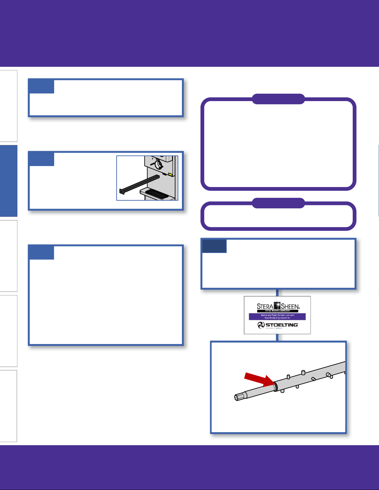
D.3
Remove the drain tray from the
front of the machine. Remove
the drip tray from the front
OPERATION INTRODUCTION
panel. Clean and replace the
trays.
D.4
The exterior of the machine should be kept clean at
MAINTENANCEPARTS TROUBLESHOOTING
all times to preserve the luster of the stainless steel.
A high grade of stainless steel has been used on the
machine to ease cleanup. To remove spilled or dried
mix, wash the exterior with 90° to 110°F (32°C to 43°C)
mild detergent water and wipe dry.
E. Assembling Machine
NOTE
Total Blend or equivalent must be used
when lubrication of machine parts is
specifi ed.
The USDA and FDA require that lubricants
used on food processing equipment must
be certifi ed for this use. Use lubricants
only in accordance with the manufacturer’s
instructions.
NOTE
Stoelting recommends allowing the parts
to air dry before assembling.
E.1
Install the rear seal o-ring onto the auger. Lubricate
the outside of the o-ring with a generous amount of
sanitary lubricant.
Do not use highly abrasive materials, as they will mar
the fi nish. A mild alkaline cleaner is recommended.
Use a soft cloth or sponge to apply the cleaner. For
best results, wipe with the grain of the steel.
10 DQU411-I2 OPERATOR’S MANUAL 513687 REV.2
Section 2: Operation
E.2
Install the adapter into the rear seal WITHOUT
LUBRICANT. Then lubricate the inside of the adapter
and install it onto the auger.
DO NOT lubricate the outside of the rear seal.
E.4
Screw the springs onto the
studs in the plastic fl ights.
The springs must be screwed
into the fl ights completely to
provide proper compression.
E.5
Install the two plastic fl ights
onto the rear of the auger
and insert it part way into the
freezing cylinder.
OPERATIONINTRODUCTION
MAINTENANCE PARTSTROUBLESHOOTING
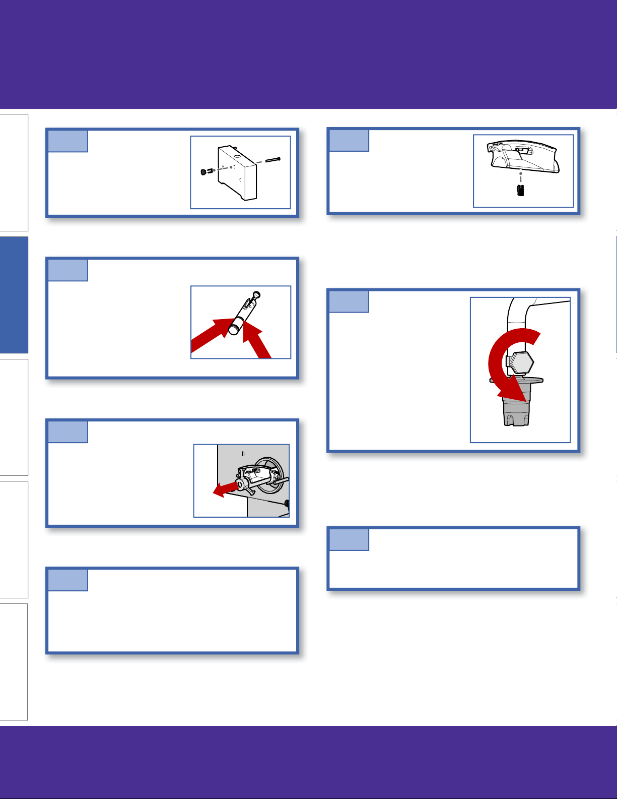
E.6
Install the remaining plastic
fl ights, push the auger into the
E.3
Lubricate the hex end of the auger with Total Blend.
513687 REV.2 DQU411-I2 OPERATOR’S MANUAL 11
freezing cylinder and rotate it
slowly until the auger engages
the drive shaft.
 Loading...