

Page 1

Model A118 / D118
OPERATORS MANUAL
Manual No. 513691 Rev.0
Page 2

Page 3

This manual provides basic information about the machine. Instructions and suggestions are
given covering its operation and care.
The illustrations and specications are not binding in detail. We reserve the right to make
changes to the machine without notice, and without incurring any obligation to modify or provide new parts for machines built prior to date of change.
DO NOT ATTEMPT to operate the machine until instructions and safety precautions in this
manual are read completely and are thoroughly understood. If problems develop or questions
arise in connection with installation, operation, or servicing of the machine, contact Stoelting.
stoeltingfoodservice.com
Stoelting Foodservice Equipment
502 Highway 67
Kiel, WI 53042-1600
U.S.A.
Main Tel: 800.558.5807
Fax: 920.894.7029
Customer Service: 888.429.5920
Fax: 800.545.0662
Email: foodservice@stoelting.com
© 2014 PW Stoelting, LLC
Page 4

A Few Words About Safety
Safety Information
Read and understand the entire manual before
operating or maintaining Stoelting equipment.
This manual provides the operator with information
for the safe operation and maintenance of Stoelting
equipment. As with any machine, there are hazards
associated with their operation. For this reason safety
is emphasized throughout the manual. To highlight
specic safety information, the following safety denitions are provided to assist the reader.
The purpose of safety symbols is to attract your attention to possible dangers. The safety symbols, and
their explanations, deserve your careful attention
and understanding. The safety warnings do not by
themselves eliminate any danger. The instructions
or warnings they give are not substitutes for proper
accident prevention measures.
If you need to replace a part, use genuine Stoelting
parts with the correct part number or an equivalent
part. We strongly recommend that you do not use
replacement parts of inferior quality.
Safety Alert Symbol:
This symbol Indicates danger, warning or caution.
Attention is required in order to avoid serious personal injury. The message that follows the symbol
contains important information about safety.
Signal Word:
Signal words are distinctive words used throughout
this manual that alert the reader to the existence and
relative degree of a hazard.
WARNING
The signal word “WARNING” indicates a potentially
hazardous situation, which, if not avoided, may result
in death or serious injury and equipment/property
damage.
CAUTION
The signal word “CAUTION” indicates a potentially
hazardous situation, which, if not avoided, may result
in minor or moderate injury and equipment/property
damage.
CAUTION
The signal word “CAUTION” not preceded by the
safety alert symbol indicates a potentially hazardous
situation, which, if not avoided, may result in equipment/property damage.
NOTE (or NOTICE)
The signal word “NOTICE” indicates information or
procedures that relate directly or indirectly to the
safety of personnel or equipment/property.
Page 5

TABLE OF
CONTENTS
Description and Specications
1.1 Description .................................................................................................. 1
1.2 Specications ............................................................................................. 2
Installation Instructions
2.1 Safety Precautions ..................................................................................... 3
2.2 Shipment and Transit .................................................................................. 3
2.3 Machine Installation .................................................................................... 3
Initial Set-Up and Operation
3.1 Operator’s Safety Precautions ................................................................... 5
3.2 Operating Controls and Indicators ............................................................. 5
3.3 Removing Mix from Machine ...................................................................... 6
3.4 Disassembly of Machine Parts ................................................................... 6
3.5 Cleaning Disassembled Parts .................................................................... 7
3.6 Cleaning the Machine ................................................................................. 7
3.7 Assembling the Machine ............................................................................ 7
3.8 Sanitizing .................................................................................................... 8
3.9 Freeze Down and Operation ...................................................................... 9
3.10 Daily Defrost ............................................................................................... 9
3.11 Consistency Adjustment ............................................................................. 9
3.12 Preventive Maintenance ............................................................................. 9
3.13 Extended Storage ....................................................................................... 10
Troubleshooting
4.1 Light Indicators ........................................................................................... 11
4.2 Troubleshooting .......................................................................................... 12
Replacement Parts
5.1 Decals and Lubrication ............................................................................... 13
5.2 Auger and Door .......................................................................................... 14
5.3 Spigot Assembly ......................................................................................... 15
5.4 Trays and Hopper Cover ............................................................................15
Page 6

Page 7
SECTION 1
DESCRIPTION AND SPECIFICATIONS
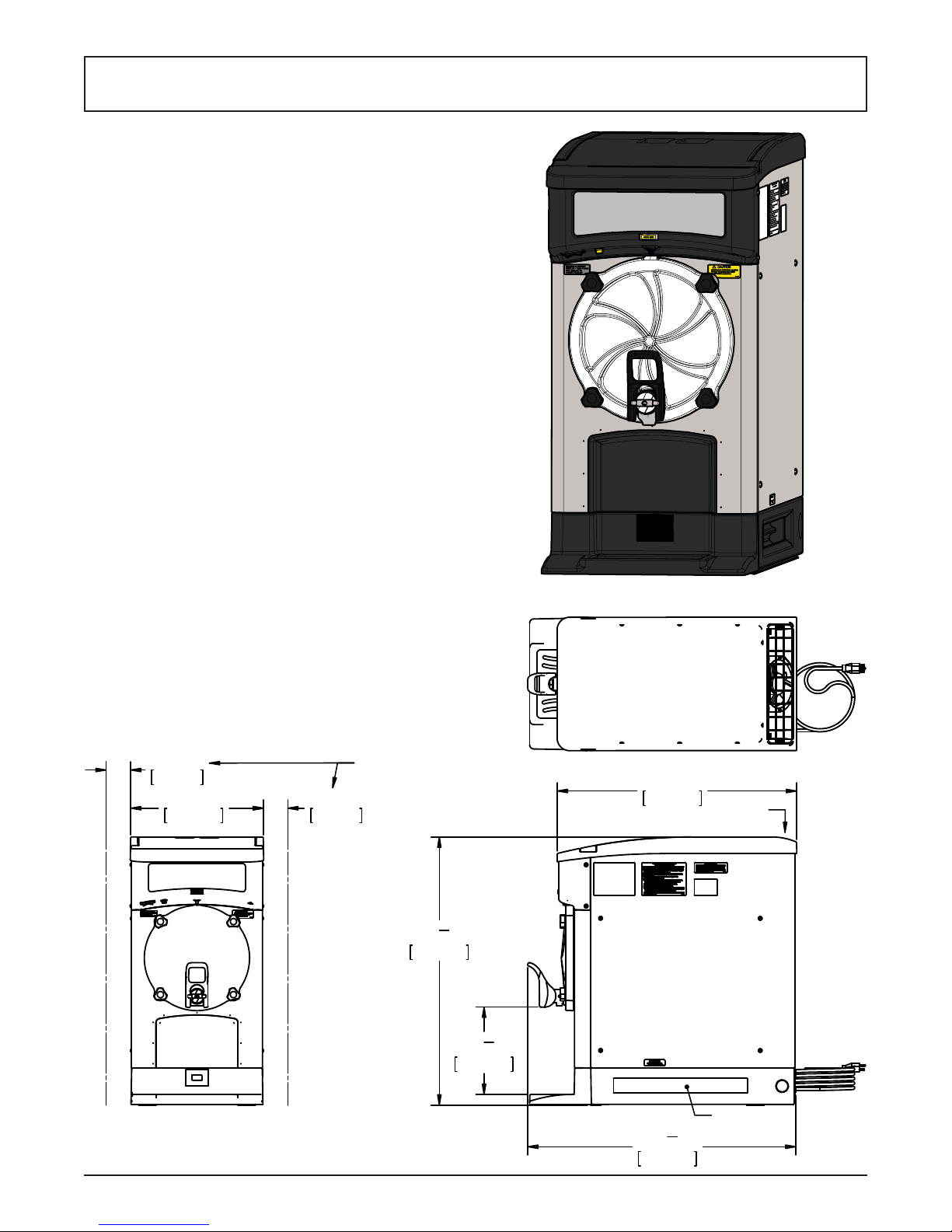
1.1 DESCRIPTION
The Stoelting A118/D118 counter machines are gravity
fed. The machines are equipped with fully automatic
controls to provide a uniform product. They operate with
almost any type of frozen beverage mix. This manual is
designed to help qualied service personnel and operators with the installation, operation and maintenance of
the Stoelting A118/D118 gravity machines.
ALL HEIGHT
DIMENSIONS +/- 1/2"
DUE TO ADJUSTABLE
LEGS
7.54cm
3"
16"
40.79cm
Figure 1-1 Model D118
CLEARANCE REQUIRED
FOR AIRFLOW
3"
7.54cm
(SIDES ONLY)
1
"
32
2
82.44cm
5
"
10
8
26.86cm
29"
73.61cm
AIR OUT
Owner’s Manual #513691 1 A118/D118 Model Machines
32
82.43cm
1
"
2
AIR IN
(BOTH SIDES)
Page 8

1.2 SPECIFICATIONS
Model A118 Model D118
Dimensions Machine with crate Machine with crate
width 16’’ (40,6 cm) 20’’ (50,8 cm) 16’’ (40,6 cm) 20’’ (50,8 cm)
height 30-5/8’’ (77,8 cm) 39-3/4’’ (101,0 cm) 30-5/8’’ (77,8 cm) 39-3/4’’ (101,0 cm)
depth 28-7/8’’ (73,3 cm) 41-1/2’’ (105,4 cm) 28-7/8’’ (73,3 cm) 41-1/2’’ (105,4 cm)
Weight 210 lbs (95,2 kg) 240 lbs (108,8 kg) 210 lbs (95,2 kg) 240 lbs (108,8 kg)
Electrical
running amps
connection type
1 Phase,
115 VAC, 60Hz
10.2A 4.7A 13.6A 8.6A
NEMA5-20P power
cord provided
Compressor 4,250 Btu/hr 8,250 Btu/hr
Drive Motor 1/7 hp
Air Flow Air cooled units require 3” (7,6 cm) air space on both sides.
Plumbing Fittings Water cooled units require 1/2” N.P.T. water and drain ttings.
Hopper Volume 5 gallon (18,93 liters)
Freezing Cylinder
Volume
1 Phase,
208-240 VAC, 60Hz
NEMA6-20P power
cord provided
2 gallon (7,57 liters)
1 Phase,
115 VAC, 60Hz
NEMAL5-30P power
cord provided
1 Phase,
208-240 VAC, 60Hz
NEMA6-20P power
cord provided
Owner’s Manual #513691 2 A118/D118 Model Machines
Page 9

SECTION 2
INSTALLATION INSTRUCTIONS
2.1 SAFETY PRECAUTIONS
Do not attempt to operate the machine until the safety
precautions and operating instructions in this manual are
read completely and are thoroughly understood.
Take notice of all warning labels on the machine. The labels have been put there to help maintain a safe working
environment. The labels have been designed to withstand
washing and cleaning. All labels must remain legible for
the life of the machine. Labels should be checked periodically to be sure they can be recognized as warning labels.
If danger, warning or caution labels are needed, indicate
the part number, type of label, location of label, and quantity
required along with your address and mail to:
STOELTING FOODSERVICE EQUIPMENT
ATTENTION: Customer Service
502 Hwy. 67
Kiel, Wisconsin 53042
2.2 SHIPMENT AND TRANSIT
The machine has been assembled, operated and inspected
at the factory. Upon arrival at the nal destination, the
entire machine must be checked for any damage which
may have occurred during transit.
With the method of packaging used, the machine should
arrive in excellent condition. THE CARRIER IS RESPON-
SIBLE FOR ALL DAMAGE IN TRANSIT, WHETHER
VISIBLE OR CONCEALED. Do not pay the freight bill
until the machine has been checked for damage. Have
the carrier note any visible damage on the freight bill. If
concealed damage and/or shortage is found later, advise
the carrier within 10 days and request inspection. The
customer must place claim for damages and/or shortages
in shipment with the carrier. Stoelting, Inc. cannot make
any claims against the carrier.
F. Place the CLEAN-ON-OFF switch in the OFF
position.
E. Connect the power cord to the proper power
supply. Check the nameplate on your machine for
proper supply. The unit must be connected to a
properly grounded receptacle. The electrical cord
furnished as part of the machine has a three prong
grounding type plug. The use of an extension
cord is not recommended, if necessary use one
with a size 12 gauge or heavier with ground wire.
Do not use an adapter to get around grounding
requirement.
F. Follow the steps in Section 3 for proper cleaning
and spigot assembly prior to operation.
2.3 MACHINE INSTALLATION
Installation of the machine involves moving the machine
close to its permanent location, removing all crating, setting in place, assembling parts, and cleaning.
A. Uncrate the machine.
B. Accurate leveling is necessary for correct drainage
of machine barrel and to insure correct overrun.
Place a bubble level on top of the machine at each
corner to check for level condition. If adjustment
is necessary, level the machine by turning the
bottom part of each leg in or out.
c. Correct ventilation is required. The machine
requires 3” clearance on both sides.
D. Install the drip tray support. Insert the pins on the
bracket into the holes on the bottom of the front
panel. Install the drip tray and drip tray grid.
Owner’s Manual #513691 3 A118/D118 Model Machines
Page 10

Owner’s Manual #513691 4 A118/D118 Model Machines
Page 11

SECTION 3
INITIAL SET-UP AND OPERATION
3.1 OPERATOR’S SAFETY PRECAUTIONS
SAFE OPERATION IS NO ACCIDENT; observe these
rules:
A. Know the machine. Read and understand the
Operating Instructions.
B. Notice all warning labels on the machine.
C. Wear proper clothing. Avoid loose tting garments,
and remove watches, rings or jewelry that could
cause a serious accident.
D. Maintain a clean work area. Avoid accidents by
cleaning up the area and keeping it clean.
E. Stay alert at all times. Know which switch, push
button or control you are about to use and what
effect it is going to have.
F. Disconnect electrical cord for maintenance. Never
attempt to repair or perform maintenance on the
machine until the main electrical power has been
disconnected.
G. Do not operate under unsafe operating conditions.
Never operate the machine if unusual or excessive
noise or vibration occurs.
3.2 OPERATING CONTROLS AND
INDICATORS
Before operating the machine, it is required that the operator know the function of each operating control. Refer
to Figure 3-1 for the location of the operating controls on
the machine.
WARNING
High voltage will shock, burn or cause death. The
OFF-ON switch must be placed in the OFF position
prior to disassembling for cleaning or servicing. Do
not operate machine with cabinet panels removed.
A. CLEAN-OFF-ON Switch
The CLEAN-OFF-ON switch is used to supply
power to the control circuit. When the switch is in
the OFF (middle) position, power is not supplied
to the control board or refrigeration system. When
the switch is in the ON position, the machine
operates in the freezing mode. When the switch
is in the CLEAN position, all refrigeration stops
and the auger starts rotating. If left in the CLEAN
position, defrost mode begins.
Clean/Off/
On Switch
Owner’s Manual #513691 5 A118/D118 Model Machines
Add Mix
Light
Diagnostic
Light
Figure 3-1 Controls
Page 12

C. ADD MIX Light
The ADD MIX light ashes to alert the operator
to a low mix condition. It does so by monitoring
the mix level in the hopper. When the ADD MIX
light is ashing, rell hopper immediately.
NOTE
Failure to rell hopper immediately may result in
operational problems.
D. Diagnostic Light
The Diagnostic Light is lit during defrost mode
and ashes if an error occurs. There are two quick
ashes if the drive motor is not sensed. Refer to
the troubleshooting section for details.
3.3 REMOVING MIX FROM MACHINE
If the machine is empty, go to Section 3.4.
A. Place the switch in the CLEAN position. Allow
the mix to agitate in freezing cylinder until the
mix has become liquid.
B. Place a container under the spigot and drain the
mix.
C. Fill the hopper with cool tap water.
D. Open the spigot to drain the water. If it is not clear
allow the cylinder to rell with water and drain it
again.
E. Place the switch in the OFF position.
3.4 DISASSEMBLY OF MACHINE PARTS
Before using the machine for the rst time, complete
machine disassembly, cleaning and sanitizing procedures
need to be followed. Routine cleaning intervals and
procedures must comply with the local and state health
codes. Inspection for worn or broken parts should be
made each time the machine is disassembled. All worn
or broken parts should be replaced to ensure safety to
both the operator and the customer and to maintain good
machine performance and a quality product.
To disassemble the machine, refer to the following steps:
B. Hold the spigot handle and turn the handle
retaining pin. Pull the handle forward and remove
it.
C. Turn the inner spigot assembly counterclockwise
90° and pull the assembly out of the spigot housing.
D. Pull the lock tab forward and turn the spigot
housing counterclockwise 90°. Pull the assembly
out of the door.
Pull lock tab forward
Pull lock tab forward
and turn housing
and turn housing
counterclockwise.
counterclockwise.
Figure 3-2 Removing Spigot Housing
E. On the inner spigot assembly, compress the valve
plug and retaining cap together and rotate the pin
90°.
F. Remove the pin, retainer cap, and spring from
the valve plug. Remove the spigot lock clip it by
squeezing it at the top and pulling downwards.
CAUTION
Hazardous Moving Parts.
Revolving auger shaft can grab and cause injury.
Place the switch in the OFF (middle) position before
disassembling for cleaning or servicing.
A. Remove the hopper cover.
Owner’s Manual #513691 6 A118/D118 Model Machines
Handle
Handle
Retaining
Retaining
Pin
Pin
Spring
Spring
Retaining Cap
Retaining Cap
Spigot Lock Clip
Spigot Lock Clip
Figure 3-3 Spigot Assembly
Valve Plug
Valve Plug
Page 13

Figure 3-4 Auger Assembly and Door
G Remove the o-rings from the spigot assemblies.
First wipe off the lubricant using a clean paper
towel. Then squeeze the o-ring upward with a dry
cloth. When a loop is formed, roll the o-ring out
of the groove.
H. Remove front door by unscrewing knobs and then
pulling the door off the studs. Remove the front
door o-ring.
I. Remove the square auger bushing.
J. Remove auger assembly from the freezing cylinder
and remove auger blades.
K. Remove rear seal and rear seal o-ring from the
auger.
3.5 CLEANING DISASSEMBLED PARTS
Disassembled parts require complete cleaning, sanitizing
and air drying before assembling. Local and state health
codes dictate the procedure required. Some state health
codes require a four sink process (pre-wash, wash, rinse,
sanitize, air dry), while others require a three sink process
(without the pre-wash step). The following procedures
are a general guideline only. Consult your local and state
health codes for the procedures required in your location.
A. Place all parts in 90° to 110°F (32°C to 43°C)
mild detergent water and wash thoroughly. Use
the brushes that shipped with the machine
to clean the parts.
B. Rinse all parts with clean 90° to 110°F (32°C to
43°C) water.
C. Place all parts in a sanitizing solution for at least
1 minute, then remove and let air dry completely
before assembling in machine.
3.6 CLEANING THE MACHINE
The exterior of the machine should be kept clean at all
times to preserve the luster of the stainless steel. A high
grade of stainless steel has been used on the machine to
ease cleanup. To remove spilled or dried mix, wash the
exterior with 90° to 110°F (32°C to 43°C) mild detergent
water and wipe dry.
Do not use highly abrasive materials, as they mar the
nish. A mild alkaline cleaner is recommended. Use a
soft cloth or sponge to apply the cleaner. For best results,
wipe with the grain of the steel.
A. Clean the rear seal surfaces on the inside of the
freezing cylinder.
B. Using sanitizing solution and the large barrel
brush provided, sanitize the freezing cylinder by
dipping the brush in the sanitizing solution and
brushing the inside of the freezing cylinder.
C. Wrap the brush in a clean sanitized cloth and
thoroughly dry the freezing cylinder.
D. Remove the drain tray, drip tray and drip tray grid
from the front of the machine. Clean and replace
them.
3.7 ASSEMBLING THE MACHINE
To assemble the machine, refer to the following steps:
NOTE
Petrol Gel sanitary lubricant or equivalent must be
used when lubrication of parts is specied.
NOTE
The United States Department of Agriculture and
the Food and Drug Administration require that lubricants used on food processing equipment be certied for this use. Use lubricants only in accordance
with the manufacturer’s instructions.
A. Install the rear seal o-ring. Lubricate the outside
of the rear seal o-ring with a generous amount
of sanitary lubricant.
B. Install the rear seal onto the auger.
Lubricate o-ring with
Lubricate o-ring with
Petrol Gel
Petrol Gel
Do not lubricate rear
Do not lubricate rear
of rear seal
of rear seal
Owner’s Manual #513691 7 A118/D118 Model Machines
Figure 3-5 Auger
Page 14

Fit bushing onto auger then
Fit bushing onto auger then
align bushing with door cutout.
align bushing with door cutout.
Figure 3-6 Align Square Bushing
C. Lubricate the drive end of the auger with a small
amount of spline lubricant. A small container of
lubricant is shipped with the machine.
D. Install the two plastic blades onto the auger and
insert the auger into the freezing cylinder. Position
the auger with the blade arms vertical and the
drive end inserted just enough to engage the
drive.
E. Apply a thin layer of sanitary lubricant to the
inside and back (side facing auger) of the square
auger support bushing. Install the bushing onto
the auger.
F. Fit the front door o-ring into the groove on the
rear of the front door.
G. Align square cutout on the front door with the
auger support bushing. Seat the bushing into the
front door then place the door onto the mounting
studs.
H. Secure the front door to the machine by placing
the knobs on the studs and tightening until nger
tight. Tighten in a crisscross pattern. Do not
overtighten. Proper o-ring seal can be observed
through the transparent front door.
I. Place the o-ring onto the spigot housing and
lubricate the o-ring with sanitary lubricant. Install
the housing into the front door.
Handle
Handle
Retaining
Retaining
Pin
Pin
Spring
Spring
Retaining Cap
Retaining Cap
Spigot Lock Clip
Spigot Lock Clip
Valve Plug
Valve Plug
Figure 3-8 Spigot Assembly
J. Assemble the spigot assembly.
1. Install the spigot lock clip into the retaining
cap.
2. Place the o-rings onto the retaining cap
and valve plug. Lubricate the o-rings with a
generous amount of sanitary lubricant.
3. Put the spring and retaining cap onto the valve
plug.
4. Press the retaining cap against the plug so
that the retaining pin can be installed.
5. Install the pin onto the shaft and turn it 90°.
K. Install the assembly into the spigot housing and
rotate the assembly clockwise 90° to secure it.
L. Install the spigot handle onto the spigot assembly.
1. Make sure the handle retaining pin is vertical.
Align the handle onto the pins in the spigot
housing.
2. Pull and rotate the retaining pin so that it locks
the handle in place.
3.8 SANITIZING
Sanitizing must be done after the machine is cleaned and
just before the hopper is lled with mix. Sanitizing the night
before is not effective. However, you should always clean
the machine and parts after each use.
The United States Department of Agriculture and
the Food and Drug Administration require that all
cleaning and sanitizing solutions used with food
processing equipment be certied for this use.
Insert spigot housing into
Insert spigot housing into
door and rotate 90º
door and rotate 90º
Figure 3-7 Install Spigot Housing
Owner’s Manual #513691 8 A118/D118 Model Machines
When sanitizing the machine, refer to local sanitary regulations for applicable codes and recommended sanitizing
products and procedures. The frequency of sanitizing
must comply with local health regulations.
Mix sanitizer according to manufacturer’s instructions to
provide a 100 parts per million (ppm) strength solution.
Mix sanitizer in quantities of no less than 2 gallons (7.5
liters) of 90° to 110°F (32° to 43°C) water. Allow sanitizer
to contact the surfaces to be sanitized for 5 minutes.
Any sanitizer must be used only in accordance with the
manufacturer’s instructions.
Page 15

A. Prepare 2 gallons of sanitizing solution. Follow
the manufacturer’s instructions for preparing the
sanitizing solution
B. Pour the sanitizing solution into the hopper.
C. Place the switch into the CLEAN position to start
the auger rotating.
D. Check for leaks at the front door seals and in the
drain tray.
E. While the cylinder is being sanitized, use a
sanitized soft bristle brush dipped in sanitizing
solution to clean the hopper and hopper cover.
F. After 5 minutes, open the spigot to drain the
sanitizing solution.
G. When the solution has drained, place the switch
in the OFF position. Allow the freezing cylinder
to drain completely.
The machine is now sanitized and ready for adding mix.
3.9 FREEZE DOWN AND OPERATION
A. Sanitize immediately before use.
B. Fill the hopper with mix. Open the spigot and drain
a small amount of mix to remove any remaining
sanitizer.
D. Place the switch in the ON position.
NOTE
After the drive motor starts, there is a delay before
the compressor starts.
F. After 15 to 20 minutes the product will be at
consistency and will be ready to serve. Freeze
down time may vary depending on mix type and
ambient temperatures.
G. To dispense, pull or push the spigot handle. To
prevent from dispensing, push the spigot lock clip
upwards.
H. Do not operate the machine when the ADD MIX
light is on. Rell the hopper immediately.
3.10 DAILY DEFROST
The machine must be placed in defrost mode on a daily
basis to prevent large ice crystal buildup.
A. Place the switch in the CLEAN position.
B. The auger rotates continuously for 20 minutes.
After 20 minutes the defrost mode begins. The
auger rotates for 90 seconds every 7 minutes
and the diagnostic light is lit.
C. Keep the machine in defrost mode for at least 4
hours daily.
D. Place the switch in the ON position to return
to freeze down product and return to normal
operation.
3.11 CONSISTENCY ADJUSTMENT
The consistency adjustment screw is located behind the
access plug on the right side panel. Remove the plug to
access the screw.
To adjust consistency, use a at head screwdriver. Turn
clockwise for thicker product and counterclockwise for
thinner product. Allow 15-30 minutes for the consistency
change to show up in the product.
3.12 PREVENTIVE MAINTENANCE
Stoelting recommends that a maintenance schedule be
followed to keep the machine clean and operating properly.
A. DAILY
1. The machine must be placed in defrost mode for
4 hours to prevent ice buildup (see Section 3.10)
2. The exterior should be kept clean at all times to
preserve the luster of the stainless steel. A mild
alkaline cleaner is recommended. Use a soft cloth
or sponge to apply the cleaner.
B. WEEKLY
1. Check o-rings and rear seal for excessive wear
and replace if necessary.
2. Remove and clean the drip tray:
a. Remove the drain tray
b. Gently lift the drip tray upwards to disengage
it from the support and pull it out.
c. Clean the drain tray and drip tray. Clean behind
the drip tray and at front of the machine with
a mild detergent.
d. Replace the drip tray and drain tray.
C. QUARTERLY
Air Cooled
The air-cooled condenser is a copper tube and aluminum
n type. Condensing is totally dependent upon airow. A
plugged condenser lter, condenser, or restrictions in the
lower vented panels lowers the capacity of the system
and may cause damage to the compressor.
The condenser must be kept clean of dirt and grease.
The machine must have a minimum of 3” ventilation on
the right and left sides of the unit for free ow of air. Make
sure the machine is not pulling over 100° F (37° C) air
from other equipment in the area.
The condenser and condenser lter require periodic cleaning. To clean, refer to the following procedures.
NOTE
The machine has a two lters. Both lters must be
cleaned.
A. Remove the drain tray. Gently lift the drip tray
upwards to disengage it from the support and
pull it out.
Owner’s Manual #513691 9 A118/D118 Model Machines
Page 16

Press Tab to Remove FilterPress Tab to Remove Filter
Figure 3-10 Filter Removal
3.13 EXTENDED STORAGE
Refer to the following steps for storage of the machine
over any long period of shutdown time:
A. Place the CLEAN-OFF-ON switch in the OFF
(middle) position.
B. Disconnect (unplug) from the electrical supply
source.
C. Clean all parts that come in contact with mix
thoroughly with a warm water cleaning solution
Rinse in clean water and dry parts. Do not sanitize.
NOTE
Do not let the cleaning solution stand in the hopper or in the freezing cylinder during the shutdown
period.
B. Remove the lower vented panels on the left and
right side of the machine by pulling the front of
the panel outward to unfasten it from the leg.
Then pull the panel forward to disengage it from
the pins.
B. Press the lter tab and pull the lter out.
C. Visually inspect the condenser lter for dirt.
D. If the lter is dirty, vacuum or brush clean, rinse
with clean water and allow to dry before replacing
on the machine.
NOTE
If the condenser is not kept clean, refrigeration efciency is lost.
Water Cooled
The water-cooled condenser is a tube and shell type. The
condenser needs a cool, clean supply of water to properly
cool the machine. Inlet and discharge lines must be 3/8”
I.D. minimum. Make sure the machine is receiving an
unrestricted supply of cold, clean water.
D. Remove, disassemble and clean the front door,
spigot and auger parts.
E. In a water cooled machine, disconnect the water
lines and drain water. With a athead screwdriver,
hold the water valve open and use compressed
air to clear the lines of any remaining water.
Owner’s Manual #513691 10 A118/D118 Model Machines
Page 17

SECTION 4
TROUBLESHOOTING
4.1 LIGHT INDICATORS
The machine has two lights that alert the user if a problem occurs: an ADD MIX light and a Diagnostic Light.
The ADD MIX light ashes to alert the operator to a low mix condition. It does so by monitoring the mix level in the
hopper. When the ADD MIX light is ashing, rell hopper immediately.
The Diagnostic Light is on during defrost mode and ashes if an error occurs. Refer to the chart below for details.
Indication On Two Blinks
Conditions Defrost Mode Drive current is not sensed
The machine attempts to sense drive current with a 3 second
Self Correction
Operation
Corrective
Action
N/A
Every 7 minutes the auger runs
for 90 seconds.
N/A Contact Service Technician
pre-stir. If current is sensed, the machine returns to normal
operation. If current is not sensed, the machine waits 7 minutes
and trys to sense current with another 3 second pre-stir. After
the third attempt, the compressor runs on timers.
Every 21 minutes the auger runs for 10 seconds.
Owner’s Manual #513691 11 A118/D118 Model Machines
Page 18

4.2 TROUBLESHOOTING
PROBLEM POSSIBLE CAUSE REMEDY
1 Power to machine is off. 1 Supply power to machine.
Machine does not
run.
Machine does not
shut off.
Product has large
ice crystals.
Product is too rm.
Product is too thin.
2 Blown fuse or tripped circuit. 2 Replace or reset.
3 Freeze-up (auger does not turn). 3 Turn Clean/Off/On switch Off for 15 minutes,
then restart.
4 Front door not in place. 4 Assemble front door in place.
1 Consistency temperature setting is too
rm.
1 Turn Consistency Adjustment knob counter-
clockwise.
2 Refrigeration problem. 2 Check system. (Call distributor for service)
1 Machine was in freeze mode without
dispensing product for an extended
period.
1 Use defrost mode daily. To use defrost mode,
turn the switch to Clean. After 20 minutes,
defrost mode automatically begins. Allow to
remain in defrost mode for at least x hours.
1 Consistency temperature setting is too
rm.
1 No vent space for free ow of cooling
air.
2 Air temperature entering condenser is
above 100°F.
1 Turn Consistency Adjustment knob counter-
clockwise.
1 A minimum of 6” of air space on both sides (the
E112 requires 3”). (See Section 2)
2 Change location or direct hot air away from
machine.
3 Condenser is dirty. 3 Clean. (See Section 3)
4 Consistency setting too soft. 4 Turn Consistency Adjustment knob clockwise.
Product does not
dispense.
Rear auger seal
leaks.
Front door leaks.
5 Auger is assembled incorrectly. 5 Remove mix, clean, reassemble, sanitize and
freeze down.
6 Refrigeration problem. 6 Check system. (Call distributor for service)
1 No mix in hopper. 1 See Auto Fill Troubleshooting section.
2 Drive motor overload tripped. 2 Press the overload reset button located under
the header panel. (If condition continues, call
distributor for service.)
3 Freeze-up (auger does not turn). 3 Turn Clean/Off/On switch Off for 15 minutes,
then restart. Make sure brix is below 10%
4 Freeze-up (mix inlet tube frozen shut). 4 Turn machine off and unplug. Use a food safe
plastic spoon handle to poke the ice blockage
through the mix inlet into the freezing cylinder.
Connect power and turn machine on.
1 Outside surface of rear auger seal is
lubricated.
1 Clean lubricant from outside of rear seal, lubri-
cate inside of seal and reinstall.
2 Rear seal missing or damaged. 2 Check or replace.
3 Seal o-ring missing, damaged or
3 Check. or replace.
installed incorrectly.
4 Worn or scratched auger shaft. 4 Replace auger shaft.
1 Front door knobs are loose. 1 Tighten knobs.
2 Spigot parts are not lubricated. 2 See Section 3.
3 Chipped or worn spigot o-rings. 3 Replace o-rings.
4 O-rings or spigot installed wrong. 4 Remove spigot and check o-ring.
5 Inner spigot hole in front door nicked
5 Replace front door.
or scratched.
Owner’s Manual #513691 12 A118/D118 Model Machines
Page 19

5.1 DECALS AND LUBRICATION
Part Number Description Quantity
C-1000-26C Decal - Made In USA 1
324105 Decal - Caution Electrical Shock 3
324106 Decal - Caution Electrical Wiring Materials 1
324107 Decal - Caution Hazardous Moving Parts 2
324141 Decal - Caution Rotating Blades 1
324208 Decal - Attention Refrigerant Leak Check 2
324509 Decal - Cleaning Instructions 1
324566 Decal - Wired According To 1
324584 Decal - Adequate Ventilation 3” 3
324686 Decal - Danger Automatic Start 2
324803 Decal - Domed Stoelting Logo (Large) (Header Panel) 1
324852 Decal - Clean Condenser Filter 1
324865 Decal - Standby Light 1
324922 Decal - Assembly Check 1
490749 Leg - Front 2
490750 Leg - Rear (w/Suction Cup) 1
508135 Petrol Gel - 4 oz Tube 1
508048 Lubricant - Spline (2 oz Squeeze Tube) 1
670547 Thread Sealant - Loctite 565 1
2183636 Spacer - Leg 4
SECTION 5
REPLACEMENT PARTS
Owner’s Manual #513691 13 A118/D118 Model Machines
Page 20

5.2 AUGER AND DOOR
625352
625352
2205308
2205308
624678
624678
2204983
2204983
666786
666786
2205002
2205002
2205672
2205672
482019
482019
Part Number Description Quantity
482019 Knob - Front Door (Black) 4
624678-5 O-Ring - Rear Seal - Black (5 Pack) 1
625352 O-Ring - Front Door - Black 1
666786 Seal - Rear Auger - Black 1
2204983 Auger 1
2205002 Blade - Scraper (Has 2) 2
2205308 Bushing - Front Auger Support (Square) 1
2205672 Door 1
Owner’s Manual #513691 14 A118/D118 Model Machines
Page 21

5.3 SPIGOT ASSEMBLY
Part Number Description Quantity
624595 O-Ring - Valve Plug (Inner) 1
624654 O-Ring - Valve Plug (Outer) 1
624663 O-Ring - Retaining Cap 1
624715 O-Ring - Spigot Housing 1
694248 Spring - Valve Plug Shaft 1
2205414 Retaining Cap - Spigot Valve 1
2205417 Housing - Spigot 1
2205369 Pin - Handle Retaining 1
2205621 Handle - Spigot Push/Pull 1
2205761 Valve Plug - Spigot 1
2205766 Lock Clip - Spigot 1
2205621
2205621
2205417
2205417
624715
624715
2205369
2205369
2205766
2205766
2205414
2205414
694248
694248
624663
624663
624595
624595
2205761
2205761
624654
624654
5.4 TRAYS AND HOPPER COVER
2205495
2205495
2205762
2205762
Part Number Description Quantity
744281 Tray - Drain (Front) 1
2205495 Cover - Hopper 1
2205497 Tray - Drip (Molded) 1
2205762 Grid - Drip Tray 1
2205497
2205497
744281
744281
Owner’s Manual #513691 15 A118/D118 Model Machines
Page 22

Owner’s Manual #513691 16 A118/D118 Model Machines
Page 23

WARRANTY
FROZEN UNCARBONATED BEVERAGE EQUIPMENT
1. Scope:
PW Stoelting, L.L.C. (“Stoelting”) warrants to the first user (the “Buyer”) that the evaporator assembly,
compressors, drive motors, and speed reducers of Stoelting frozen uncarbonated beverage
equipment will be free from defects in materials and workmanship under normal use and proper
maintenance appearing within five (5) years, and that all other components of such equipment
manufactured by Stoelting will be free from defects in material and workmanship under normal use
and proper maintenance appearing within twelve (12) months after the date that such equipment is
originally installed.
2. Disclaimer of Other Warranties:
THIS WARRANTY IS EXCLUSIVE; AND STOELTING, HEREBY DISCLAIMS ANY
IMPLIED WARRANTY OF MERCHANTABILITY OR FITNESS FOR PARTICULAR
PURPOSE.
3. Remedies:
Stoelting’s sole obligations, and Buyer’s sole remedies, for any breach of this warranty shall be the
repair or (at Stoelting’s option) replacement of the affected component at Stoelting’s plant in Kiel,
Wisconsin, or (again, at Stoelting’s option) refund of the purchase price of the affected equipment,
and, during the first twelve (12) months of the warranty period, deinstallation/reinstallation of the
affected component from/into the equipment. Those obligations/remedies are subject to the
conditions that Buyer (a) signs and returns to Stoelting, upon installation, the Start-Up and Training
Checklist for the affected equipment, (b) gives Stoelting prompt written notice of any claimed breach
of warranty within the applicable warranty period, and (c) delivers the affected equipment to Stoelting
or its designated service location, in its original packaging/crating, also within that period. Buyer shall
bear the cost and risk of shipping to and from Stoelting’s plant or designated service location.
4. Exclusions and Limitations:
This warranty does not extend to parts, sometimes called “wear parts”, which are generally expected
to deteriorate and to require replacement as equipment is used, including as examples but not
intended to be limited to o-rings, hoses, seals, and drive belts. All such parts are sold
AS IS.
Further, Stoelting shall not be responsible to provide any remedy under this warranty with respect to
any component that fails by reason of negligence, abnormal use, misuse or abuse, use with parts or
equipment not manufactured or supplied by Stoelting, or damage in transit.
THE REMEDIES SET FORTH IN THIS WARRANTY SHALL BE THE SOLE LIABILITY
STOELTING AND THE EXCLUSIVE REMEDY OF BUYER WITH RESPECT TO
EQUIPMENT SUPPLIED BY STOELTING; AND IN NO EVENT SHALL STOELTING
BE LIABLE FOR ANY INCIDENTAL OR CONSEQUENTIAL DAMAGES, WHETHER
FOR BREACH OF WARRANTY OR OTHER CONTRACT BREACH, NEGLIGENCE OR
OTHER TORT, OR ON ANY STRICT LIABILITY THEORY.
SFWARR-105
Revision 0
Page 1 of 1
 Loading...