

Page 1

Model CF101
SERVICE MANUAL
Manual No. 513644 Mar. 2009
Page 2

Page 3

This manual provides basic information about the machine. Instructions and suggestions are
given covering its operation and care.
The illustrations and specifi cations are not binding in detail. We reserve the right to make
changes to the machine without notice, and without incurring any obligation to modify or provide new parts for machines built prior to date of change.
DO NOT ATTEMPT to operate the machine until instructions and safety precautions in this
manual are read completely and are thoroughly understood. If problems develop or questions
arise in connection with installation, operation, or servicing of the machine, contact Stoelting.
stoeltingfoodservice.com
Stoelting Foodservice Equipment
502 Highway 67
Kiel, WI 53042-1600
U.S.A.
Main Tel: 800.558.5807
Fax: 920.894.7029
Customer Service: 888.429.5920
Fax: 800.545.0662
Email: foodservice@stoelting.com
© 2014 PW Stoelting, LLC
Page 4

A Few Words About Safety
Safety Information
Read and understand the entire manual before
operating or maintaining Stoelting equipment.
This manual provides the operator with information
for the safe operation and maintenance of Stoelting
equipment. As with any machine, there are hazards
associated with their operation. For this reason safety
is emphasized throughout the manual. To highlight
specifi c safety information, the following safety defi ni-
tions are provided to assist the reader.
The purpose of safety symbols is to attract your attention to possible dangers. The safety symbols, and
their explanations, deserve your careful attention
and understanding. The safety warnings do not by
themselves eliminate any danger. The instructions
or warnings they give are not substitutes for proper
accident prevention measures.
If you need to replace a part, use genuine Stoelting
parts with the correct part number or an equivalent
part. We strongly recommend that you do not use
replacement parts of inferior quality.
Safety Alert Symbol:
This symbol Indicates danger, warning or caution.
Attention is required in order to avoid serious personal injury. The message that follows the symbol
contains important information about safety.
Signal Word:
Signal words are distinctive words used throughout
this manual that alert the reader to the existence and
relative degree of a hazard.
WARNING
The signal word “WARNING” indicates a potentially
hazardous situation, which, if not avoided, may result
in death or serious injury and equipment/property
damage.
CAUTION
The signal word “CAUTION” indicates a potentially
hazardous situation, which, if not avoided, may result
in minor or moderate injury and equipment/property
damage.
CAUTION
The signal word “CAUTION” not preceded by the
safety alert symbol indicates a potentially hazardous
situation, which, if not avoided, may result in equipment/property damage.
NOTE (or NOTICE)
The signal word “NOTICE” indicates information or
procedures that relate directly or indirectly to the
safety of personnel or equipment/property.
Page 5

TABLE OF
CONTENTS
Section Description Page
1 Description and Specifications
1.1 Description.................................................................................................1
1.2 Specifications............................................................................................. 2
2 Installation Instructions
2.1 Safety Precautions.....................................................................................3
2.2 Shipment and Transit.................................................................................3
2.3 Machine Installation ...................................................................................3
3 Initial Set-Up and Operation
3.1 Operator’s Safety Precautions ...................................................................5
3.2 Operating Controls and Indicators .............................................................5
3.3 Sanitizing ...................................................................................................6
3.4 Freeze Down and Operation ......................................................................7
3.5 Mix Information ..........................................................................................8
3.6 Removing Mix from Machine .....................................................................8
3.7 Cleaning the Machine ................................................................................8
3.8 Disassembly of Machine Parts...................................................................8
3.9 Cleaning the Machine Parts.......................................................................9
3.10 Assembly of Machine.................................................................................9
3.11 Routine Cleaning .......................................................................................10
3.12 Cleaning and Sanitizing Information...........................................................10
4 Maintenance and Adjustments
4.1 Machine Adjustment ..................................................................................13
4.2 Obtaining Readings and Modifying Settings (Service Personnel Only) ......13
4.3 Readings (Service Personnel Only) ...........................................................13
4.4 Settings (Service Personnel Only) .............................................................14
4.5 Drive Belt Tension Adjustment...................................................................15
4.6 Preventative Maintenance..........................................................................15
4.7 Extended Storage ......................................................................................16
Page 6

Section Description Page
5 Refrigeration System
5.1 Refrigeration System .................................................................................17
5.2 Refrigerant Recovery and Evacuation........................................................17
5.3 Refrigerant Charging..................................................................................18
5.4 Compressor...............................................................................................19
5.5 Condenser .................................................................................................20
5.6 Evaporator .................................................................................................20
5.7 Valves........................................................................................................20
A. Thermostatic Expansion Valve (TXV)..................................................................20
B. Check Valve ........................................................................................................21
C. High Pressure Cutout ..........................................................................................22
D. Hot Gas Bypass ...................................................................................................22
E. Evaporator Pressure Regulator (EPR) ................................................................23
5.8 Solenoid.....................................................................................................23
5.9 Filter Drier..................................................................................................25
5.10 Capillary Tube............................................................................................25
5.11 Receiver ....................................................................................................25
6 Electrical and Mechanical Control Systems
6.1 IntelliTec Controller....................................................................................27
6.2 Contactors .................................................................................................27
6.3 Drive Motor ................................................................................................28
6.4 Capacitors .................................................................................................29
6.5 Gearbox.....................................................................................................29
6.6 Condenser Fan Motor................................................................................30
6.7 Potential Relay...........................................................................................30
6.8 Temperature Control Sensor .....................................................................30
7 Troubleshooting
7.1 Error Codes ...............................................................................................31
7.2 Troubleshooting Error Codes.....................................................................31
7.3 Troubleshooting Tables .............................................................................33
8 Replacement Parts
8.1 Decals and Lubrication ..............................................................................35
8.2 Panels and Panel Screws ..........................................................................35
8.3 Beater Shaft and Faceplate Parts ..............................................................36
8.4 Hopper Parts and Trays.............................................................................37
8.5 Electrical Panel ..........................................................................................38
8.6 Front ..........................................................................................................39
8.7 Rear...........................................................................................................40
8.8 Left Side ....................................................................................................41
8.9 Wiring Diagram..........................................................................................42
Page 7

SECTION 1
DESCRIPTION AND SPECIFICATIONS
1.1 DESCRIPTION
The CF101 is a counter top continuous flow custard
machine. It is equipped with fully automatic controls to
provide a uniform product and features Quick-Freeze
technology. This manual is designed to assist qualified
service personnel and operators in the installation, operation and maintenance of the CF101 frozen custard machine.
Figure 1-1 Model CF101
Figure 1-2 MachineSpecifications
1
Page 8
1.2 SPECIFICATIONS
z
Dimensions
width
height
depth
Weight
Electrical
conn ection type
Compressor
Drive M ot or
Air Fl ow
Hopper Volum e
Freezing Cyl i nder
Volume
Superheat out of
CF101
Machi ne with cr at e
19-1/ 2' ' ( 49, 5 c m ) 38-3/ 4'' (9 8, 4 cm )
37-3/ 4' ' ( 95, 9 c m ) 28-3/ 4'' (7 3, 0 cm )
28'' (71,1 cm) 43'' (109,2 cm)
310 lbs (140 , 6 kg) 380 lbs ( 172,3 kg)
1 Phase, 208-240 VA C, 60Hz
NEM A6-20P power cord provided
14,000 Bt u/ hr
1-1/2 h p
Air cooled units r equire 6" ( 15, 2 cm ) air space at l e f t and r ight sides and 10"
(25, 4) air spa ce above t he m achine.
5.4 gallon (30,28 l iters)
0.8 gallon ( 3. 2 quart), 3,03 l it ers
CF101
Refrigerant
Charge
Evaporator
R-404A
No Receiver 64 oz
With Receiver 80 o
8°F
Suction Pr essur e
(at 72° F)
Discharge Pr essur e
Hot Gas Bypass
Pressure
EPR Valve
Menu Display Value
Product 1
Product 2
Standby
Storage
Freezin g Cyl inder On ly 19- 20 psig
Freezin g Cyl inder & H opper 23 ps ig
Hopper O nly 14 ps ig
235-305 p sig
14 psig (on ly hopper ru nnin g)
46-48 psig
Cut In T 3 °F
Cut Out T -20 °F
Cut In T 3 °F
Cut Out T -13 °F
On T ime 180 seconds
Of f Time 30 secon ds
Cut In T
Cut Out T
On T ime 60 seconds
Of f Time 900 secon d s
HprCutIn 27.5 °F
HprCtOut 26.5 °F
Hpr O n 100 secon d s
Hpr Off 6 minutes
35 °F w/Receiver
25 °F w / o R eceiver
25 °F w/Receiver
15 °F w / o R eceiver
2
Page 9
SECTION 2
INSTALLATION INSTRUCTIONS
2.1 SAFETY PRECAUTIONS
Do not attempt to operate the machine until the safety
precautions and operating instructions in this manual are
read completely and are thoroughly understood.
Take notice of all warning labels on the machine. The
labels have been put there to help maintain a safe working
environment. The labels have been designed to withstand
washing and cleaning. All labels must remain legible for
the life of the machine. Labels should be checked periodically to be sure they can be recognized as warning labels.
If danger, warning or caution labels are needed, indicate
the part number, type of label, location of label, and
quantity required along with your address and mail to:
STOELTING, INC.
A TTENTION: Customer Service
502 Hwy . 67
Kiel, Wisconsin 53042
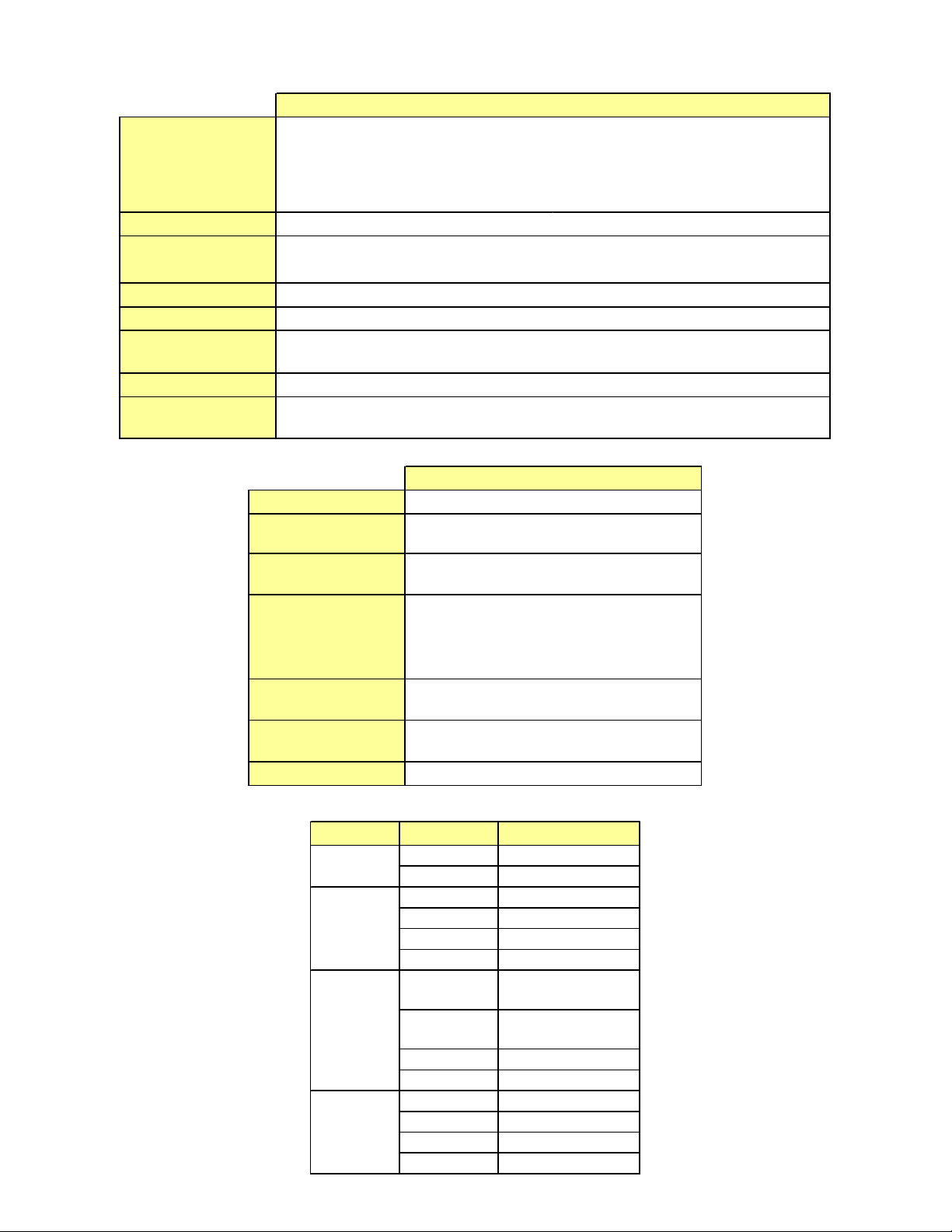
Figure 2-2 Space and Ventilation Requirements
CAUTION
Failure to provide adequate ventilation will void warranty .
2.2 SHIPMENT AND TRANSIT
The machine has been assembled, operated and inspected at the factory. Upon arrival at the final destination,
the entire machine must be checked for any damage
which may have occurred during transit.
With the method of packaging used, the machine should
arrive in excellent condition. THE CARRIER IS RESPONSIBLE FOR ALL DAMAGE IN TRANSIT, WHETHER
VISIBLE OR CONCEALED. Do not pay the freight bill until
the machine has been checked for damage. Have the
carrier note any visible damage on the freight bill. If
concealed damage and/or shortage is found later, advise
the carrier within 10 days and request inspection. The
customer must place claim for damages and/or shortages
in shipment with the carrier. Stoelting, Inc. cannot make
any claims against the carrier.
2.3 MACHINE INSTALLATION
Installation of the machine involves moving the machine
close to its permanent location, removing all crating,
setting in place, assembling parts, and cleaning.
A. Uncrate the machine.
B. Accurate leveling is necessary for correct drainage
of the freezing cylinder and to insure correct
overrun. Place a bubble level on top of the machine
at each corner to check for level condition. If
adjustment is necessary, level the machine by
turning the bottom part of each leg in or out. Then
separate machine base gasket and install with
seam to the back and angle to the top.
C. Correct ventilation is required. The CF101 requires
a minimum of 6" (15,2 cm) air space at left and
right sides and 10" (25,4) air space above the
machine.
D. Place the Main Freezer Power Off/On switch in
the Off position.
E. Connect the power cord to the proper power
supply. The plug is designed for 208-240 Volt/20
amp duty. Check the nameplate on your machine
for the proper supply. The unit must be connected
to a properly grounded receptacle. The electrical
cord furnished as part of the machine has a three
prong grounding type plug. The use of an extension
cord is not recommended, if necessary use one
with a size 12 gauge or heavier with ground wire.
Do not use an adapter to get around grounding
requirement.
WARNING
Do not alter or deform electrical plug in any way.
Altering the plug to fit into an outlet of different configuration may cause fire, risk of electrical shock,
product damage and will void warranty .
3
Page 10

4
Page 11

SECTION 3
INITIAL SET-UP AND OPERATION
3.1 OPERATOR’S SAFETY PRECAUTIONS
SAFE OPERATION IS NO ACCIDENT; observe these
rules:
A. Know the machine. Read and understand the
Operating Instructions.
B. Notice all warning labels on the machine.
C. Wear proper clothing. Avoid loose fitting garments,
and remove watches, rings or jewelry that could
cause a serious accident.
D. Maintain a clean work area. Avoid accidents by
cleaning up the area and keeping it clean.
E. Stay alert at all times. Know which switch, push
button or control you are about to use and what
effect it is going to have.
F. Disconnect electrical cord for maintenance. Never
attempt to repair or perform maintenance on the
machine until the main electrical power has been
disconnected.
G. Do not operate under unsafe operating conditions.
Never operate the machine if unusual or excessive
noise or vibration occurs.
3.2 OPERATING CONTROLS AND INDICATORS
Before operating the machine, it is required that the
operator know the function of each operating control.
Refer to Figure 3-1 for the location of the operating
controls on the machine.
WARNING
High voltage will shock, burn or cause death. The
Off/On switch must be placed in the OFF position
prior to disassembling for cleaning or servicing. Do
not operate machine with cabinet panels removed.
A. Main Freezer Power Off/On Switch
The Main Freezer Power Off/On switch is a twoposition toggle switch used to supply power to the
control circuit. When the switch is in the Off
position, power will not be supplied to the control
board or refrigeration system. When the switch is
put in the On position, the machine will be in
standby mode. The display will read Standby and
the amber LED will light.
Main Freezer
Power Off/On
Product
Selector
Switch
IntelliT ec Control
(See Figure 3-2)
Figure 3-1 CF101 Controls
5
Page 12

B. Product Selector Switch
The product selector switch changes the
refrigeration profile to allow two different products
to be made. Before the machine is in ready mode,
this switch can be moved to the desired profile.
C. PUSH TO FREEZE Button
The PUSH TO FREEZE button is used to initiate
the run mode. To start the machine, place the
Main Freezer Power Off/On switch in the On
position and press the PUSH TO FREEZE button.
D. LEDs
The membrane switch features two lights; a green
LED and an amber LED. The green LED will flash
when the freezing cylinder is near ready mode
and stay lit during ready mode. The amber LED is
lit during standby, purge and clean modes.
NOTE
If the machine enters an error condition, alternating
green and amber lights will flash. The LCD will display an error. Turn the Main Freezer Power Off/On
switch to the OFF position, correct the problem (Refer to Troubleshooting in Section 4) and turn the
machine back on.
E. PURGE/CLEAN Button
PURGE Mode - When the PURGE/CLEAN button
is pressed, the beater shaft will rotate. A PURGE
message will display on the screen along with a 5
minute timer. Hopper refrigeration will continue to
run. When the timer gets to 0:00 and no other
buttons are pressed, the machine will go into
standby mode.
CLEAN Mode - During PURGE mode, if the
PURGE/CLEAN button is pressed and held for 3
seconds, the CLEAN mode will begin. The beater
shaft will continue to rotate and hopper refrigeration
will stop.
F. Mix Low Light Indicator
The MIX LOW message will appear on the LCD
display when there is approximately one gallon of
mix left in the hopper. When the MIX LOW
message is displayed, refill hopper immediately.
NOTE
Failure to refill hopper immediately may result in
operational problems.
G. Menu Navigation Buttons
The Menu Navigation Buttons are primarily used
for machine calibration.
Selection Button (SEL) The SEL button is not
functional in the normal operation mode. This
button is only used by service technicians for
machine calibration.
Push to Freeze
Green LED
Amber LED
Purge/Clean
Button
SEL Button
SET Button
Left Arrow Button
Up Arrow Button
Figure 3-2 IntelliT ec Control
Set Button (SET) The SET button is not functional
in the normal operation mode. This button is only
used by service technicians for machine
calibration.
Left Arrow Button (Õ) Pressing any button on
the control panel will automatically illuminate the
display. The backlight will turn off several seconds
after use. To keep the display constantly lit, press
and hold the left (Õ) button for five seconds. The
backlight function can be reset to normal operation
in the same manner.
Up Arrow Button (×) The × button is not
functional in the normal operation mode. This
button is only used by service technicians for
machine calibration.
H. Front Door Safety Switch
The front door safety switch prevents the beater
shaft from turning when the front door is removed.
The switch is open when the door is not in place
and closed when the door is properly installed.
3.3 SANITIZING
Sanitizing must be done after the machine is cleaned and
just before the hopper is filled with mix. Sanitizing the night
before is not effective. However, you should always clean
the machine and parts after each use.
THE UNITED STATES DEPARTMENT OF AGRICUL TURE AND THE FOOD AND DRUG ADMINISTRA TION REQUIRE THA T ALL CLEANING AND
SANITIZING SOLUTIONS USED WITH FOOD
PROCESSING EQUIPMENT BE CERTIFIED FOR
THIS USE.
When sanitizing the machine, refer to local sanitary regulations for applicable codes and recommended sanitizing
products and procedures. The frequency of sanitizing
must comply with local health regulations.
6
Page 13
Mix sanitizer according to manufacturer’s instructions to
provide a 100 parts per million strength solution. Mix
sanitizer in quantities of no less than 2 gallons (7.5 liters)
of 90° to 110°F (32° to 43°C) water. Allow sanitizer to
contact the surfaces to be sanitized for 5 minutes. Any
sanitizer must be used only in accordance with the
manufacturer’s instructions.
In general, sanitizing may be conducted as follows:
A. Prepare Stera-Sheen Green Label Sanitizer or
equivalent according to manufacturer’s
instructions to provide a 100ppm strength solution.
Mix the sanitizer in quantities of no less than 2
gallons of 90° to 110°F (32° to 43°C) water. Any
sanitizer must be used only in accordance with
the manufacturer’s instructions.
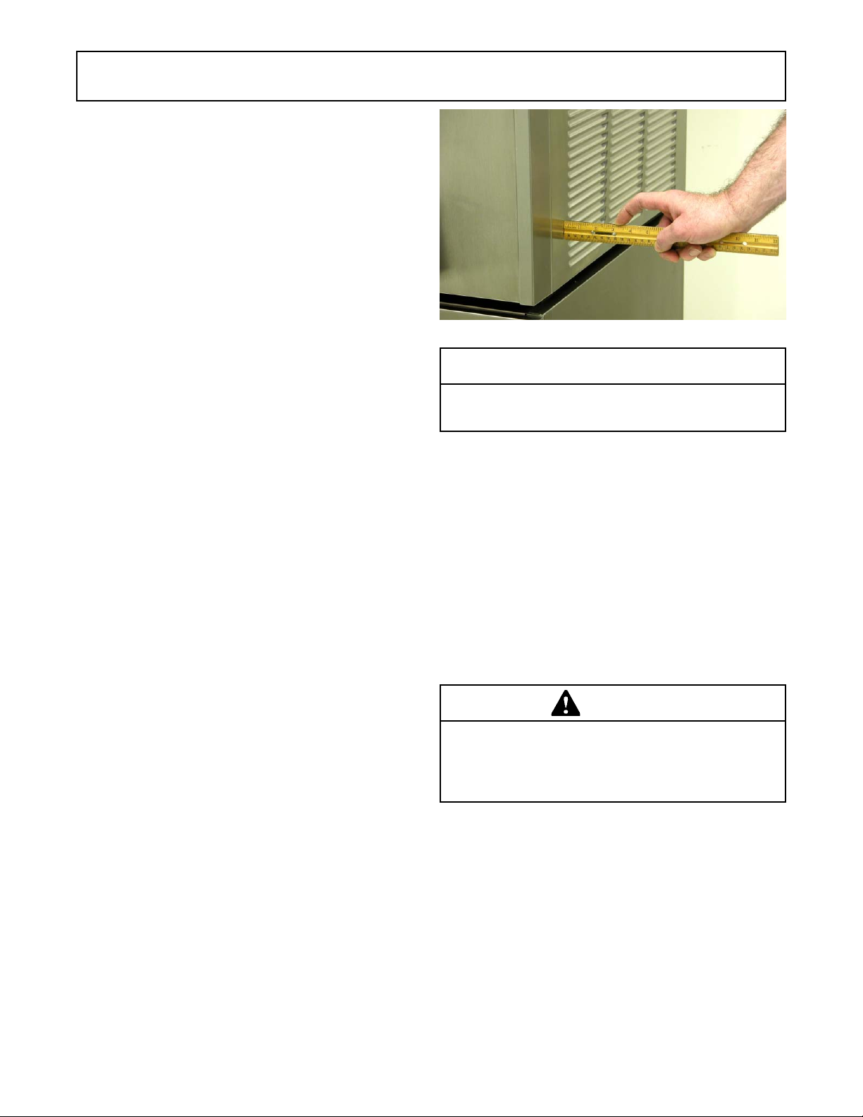
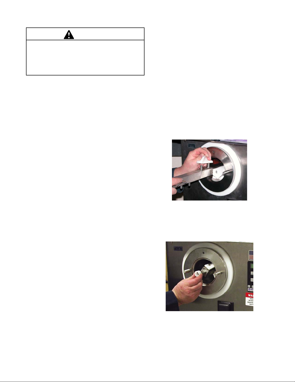
B. Place the tapered end of the flow valve into the
hopper drain hole with the arm pointing towards
the left. Connect the flow control rod to the flow
valve and the flow valve arm (Fig. 3-3).
I. When the sanitizer has drained from the hopper,
press and hold the PURGE/CLEAN button for 3
seconds to stop the beater shaft. Allow the freezing
cylinder to drain completely.
J. Shut off the flow control valve by turning the flow
control knob counterclockwise to the 12:00
position.
3.4 FREEZE DOWN AND OPERATION
This section covers the recommended operating procedures to be followed for the safe operation of the machine.
A. Sanitize just prior to use.
NOTE
Make sure the flow control assembly is in place before adding mix and that the flow control knob is set
to the 12:00 position.
B. Fill hopper with approximately 3 gallons (11.4
liters) of pre-chilled (40°F or 4°C) mix.
E. Place the Main Freezer Power Off/On switch in
the On position. The display will read STANDBY
MODE.
F. Press the PUSH TO FREEZE button. The display
will read CUSTARD and a bar on the second line
will start to fill. For PRODUCT 2, move the product
selector switch to the PRODUCT 2 position.
NOTE
The product selector switch can be changed until
the READY message is displayed on the second
line.
Figure 3-3 Flow Control Assembly
C. Make sure the flow control valve is shut by turning
the control knob counterclockwise to the 12:00
position.
D. Place a bucket under the slide.
E. Pour the sanitizer into the hopper.
NOTE
A small amount of sanitizer may drain into the bucket
with the flow control shut.
F. Place the Main Freezer Power Off/On switch in
the On position and press the PURGE/CLEAN
button. The display will read PURGE.
G. Press and hold the PURGE/CLEAN button for 3
seconds. The display will read CLEAN and a 20
minute timer will start.
G. Turn the flow control knob fully open (clockwise).
H. Clean sides of hopper, flow valve and underside
of hopper cover using a sanitized soft bristle brush
dipped in the sanitizing solution.
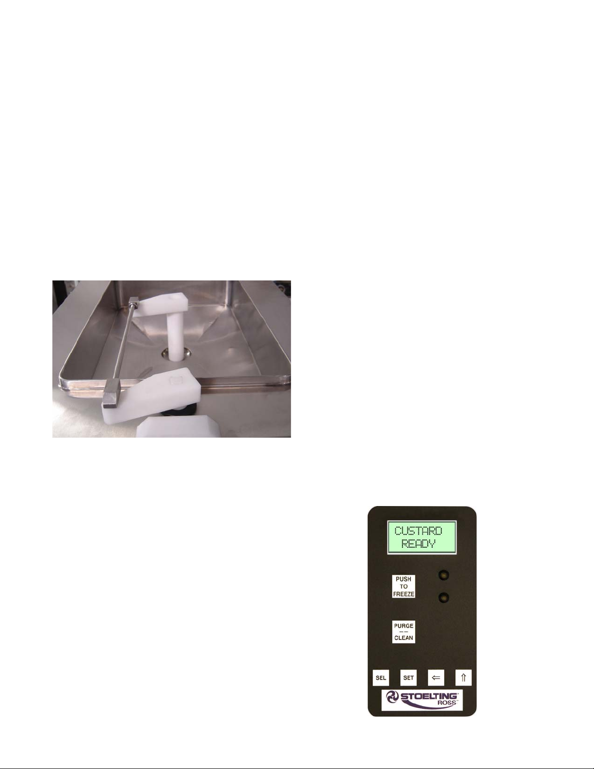
G. When the display reads CUSTARD READY, the
freezing cylinder is at the correct temperature
(Fig. 3-4).
H. Open the front gate.
I. Turn the flow control knob clockwise to the 6:00
Figure 3-4 Custard Mode
7
Page 14
position. A small amount of mix and remaining
sanitizer will drain from the machine.
J. Turn the flow control knob between the 1:00-2:00
position for vanilla or between the 5:00-6:00 for
chocolate. After a few minutes, a ribbon of product
starts to form.
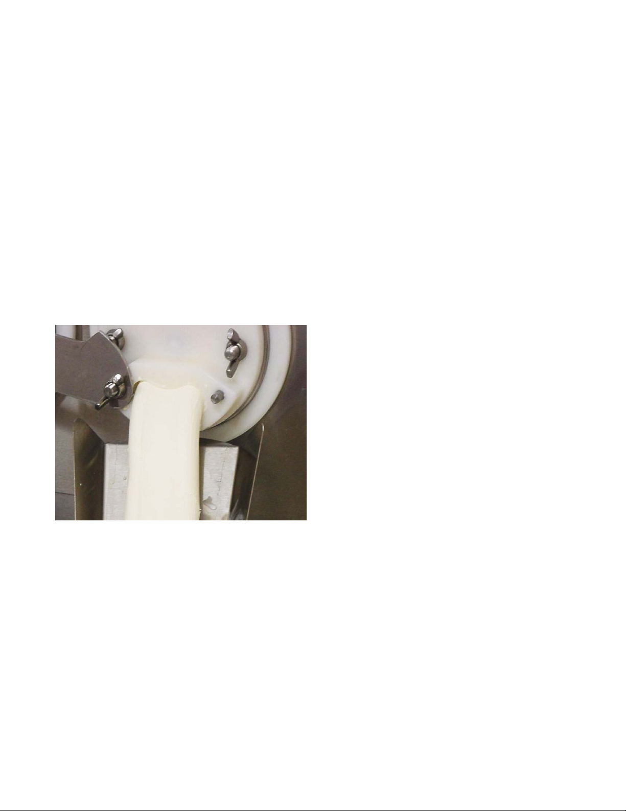
K. Adjust the flow control knob until the product flow
fills the faceplate outlet and is at the desired
texture (Fig. 3-5). The flow control knob setting
will be different for each type of product.
NOTE
Adjustments take up to 1 minute before a noticeable difference is seen in the product.
NOTE
A high-pitched noise from the freezing cylinder is
an indication that there is not enough mix entering
the freezing cyliner. Slowly turn the flow control knob
clockwise to increase the flow. It can take up to 1
minute for the adjustment to stop the noise.
Figure 3-5 Proper Flow
3.5 MIX INFORMATION
Mix can vary considerably from one manufacturer to
another. Differences in the amount of butterfat content
and the quantity and quality of other ingredients have a
direct bearing on the finished frozen product. A change in
machine performance that cannot be explained by a
technical problem may be related to the mix.
Proper product serving temperature varies from one
manufacturer’s mix to another. When checking the temperature, stir the thermometer in the frozen product to read
the true temperature.
Old mix or mix that has been stored at elevated temperatures will produce poor-quality product with a bad taste and
unacceptable appearance. To retard bacteria growth in
dairy based mixes, the best storage temperature range is
between 36° to 40°F (2.2° to 4.4°C).
3.6 REMOVING MIX FROM MACHINE
To remove the mix from the machine, refer to the following
steps. Make sure the gate on the faceplate is open.
A. Press the PURGE/CLEAN button. The display
will read PURGE.
B. Press and hold the PURGE/CLEAN button for 3
seconds. The display will read CLEAN and a 20
minute timer will start.
C. Open the flow control valve fully by turning the flow
control knob clockwise until the pointer is near the
12:00 position.
D. After the hopper and freezing cylinder have
drained, place the Main Freezer Power Off/On
switch in the OFF position.
3.7 CLEANING THE MACHINE
NOTE
The frequency of cleaning the machine and machine
parts must comply with local health regulations.
After the mix has been removed from the machine, the
machine must be cleaned. To clean the machine, refer to
the following steps:
A. Place a container under the slide of the faceplate.
Fill the hopper with 2 gallons (7.5 liters) of tap
water.
B. Place the Main Freezer Power Off/On switch in
the On position. Press the PURGE/CLEAN button.
The display will read PURGE.
C. Press and hold the PURGE/CLEAN button for 3
seconds. The display will read CLEAN and a 20
minute timer will start.
D. When the water has drained, place the switch in
the OFF position. Allow the freezing cylinder to
drain completely.
E. Prepare detergent water by mixing 2 oz. of
Palmolive detergent or equivalent in 2 gallons of
90° to 110°F (32° to 43°C) water. Repeat steps A
through D using the detergent solution.
3.8 DISASSEMBLY OF MACHINE PARTS
Inspection for worn or broken parts should be made each
time the machine is disassembled. All worn or broken
parts should be replaced to ensure safety to both the
operator and the customer and to maintain good machine
performance and a quality product. Frequency of cleaning
must comply with local health regulations.
8
Page 15
To disassemble the machine, refer to the following steps:
CAUTION
Hazardous Moving Parts
A revolving beater shaft shaft can grab and cause
injury . Place the Main Freezer Power Off/On switch
in the OFF position before disassembling for cleaning or servicing.
A. Remove the flow control rod and flow control
valve from the hopper by pulling straight up.
C. Remove the slide from the faceplate and remove
the faceplate.
D. Remove the beater shaft wearguard.
F. Remove the beater shaft assembly from the
machine. Pull the beater shaft out of the freezing
cylinder slowly. As it is being pulled out, carefully
remove each of the blades and springs.
G. Remove the seal from the back of the beater
shaft.
I. Wipe socket lubricant from the drive end (rear) of
the beater shaft with a cloth or paper towel.
NOTE
The United States Department of Agriculture and
the Food and Drug Administration require that lubricants used on food processing equipment be certified for this use. Use lubricants only in accordance
with the manufacturer’s instructions.
A. Coat the rear seal with a generous amount of
Petrol Gel.
B. Install the rear seal onto the beater shaft.
C. Lubricate the drive (rear) end of the beater shaft
with a small amount of white socket lubricant. A
small container of socket lubricant is shipped with
the machine.
D. Install two of the springs and blades onto the rear
of the beater shaft and insert the shaft part way
into freezing cylinder. Rotate the shaft so another
spring and blade can be placed onto it.
3.9 CLEANING THE MACHINE PARTS
Place all loose parts in a pan or container and take to the
wash sink for cleaning. To clean the parts refer to the
following steps:
A. Prepare detergent water by mixing 2 oz. of
Palmolive detergent or equivalent in 2 gallons of
90° to 110°F (32° to 43°C) water.
B. Place all parts in detergent solution and clean with
the provided brushes.
C. Wash the hopper and freezing cylinder with the
detergent water and brushes provided.
D. Wash the inside of the freezing cylinder with the
detergent water.
E. Rinse all parts with clean 90° to 110°F (32° to
43°C) water.
NOTE
If the machine is not going to be immediately operated, store the faceplate in a clean and sanitized
container in a cooler.
3.10 ASSEMBLY OF MACHINE
To assemble the machine parts, refer to the following
steps:
NOTE
Petrol Gel sanitary lubricant or equivalent must be
used when lubrication of parts is specified.
Figure 3-6 Installing Blades
E. Install the remaining blades, push the beater shaft
into the freezing cylinder and rotate it slowly until
the shaft engages the drive coupling.(Fig. 3-6).
Figure 3-7 Install Front Wear Bushing
F. Lubricate the inside and outside of the wearguard
and install it onto the beater shaft (Fig. 3-7).
9
Page 16

Figure 3-8 Install Faceplate
G. Install the large o-ring onto the front plate and
install the faceplate onto the machine (Fig. 3-8).
H. Install slide, hopper cover and drain tray.
3.11 ROUTINE CLEANING
To remove spilled or dried mix from the machine exterior,
wash in the direction of the finish with warm soapy water
and wipe dry. Do not use highly abrasive materials, as they
will mar the finish.
3.12 CLEANING AND SANITIZING
INFORMATION
Special consideration is required when it comes to food
safety and proper cleaning and sanitizing.
The following information has been compiled by Purdy
Products Company, makers of Stera-Sheen Green Label
Cleaner/Sanitizer and specifically covers issues for cleaning and sanitizing frozen dessert machines. This information is meant to supplement a comprehensive food safety
program.
SOIL MATERIALS ASSOCIATED WITH FROZEN
DESSERT MACHINES
MILKFAT/BUTTERFAT – As components of ice-cream/
frozen custard mix, these soils will accumulate on the
interior surfaces of the machine and its parts. Fats are
difficult to remove and help attribute to milkstone buildup.
MILKSTONE – Is a white/gray film that forms on equipment and utensils that come in contact with dairy products.
These films will accumulate slowly on surfaces because of
ineffective cleaning, use of hard water, or both. Milkstone
is usually a porous deposit, which will harbor microbial
contaminants and eventually defy sanitizing efforts.
Once milkstone has formed, it is very difficult to remove.
Without using the correct product and procedure, it is
nearly impossible to remove a thick layer of milkstone.
(NOTE: general-purpose cleaners DO NOT remove
milkstone.) This can lead to high bacteria counts and a
food safety dilemma.
IT IS BEST TO CONTROL MILKSTONE ON A DAILY
BASIS BEFORE IT CAN BECOME A SIGNIFICANT FOOD
SAFETY PROBLEM.
In addition to food safety, milkstone can cause premature
wear to machine parts which can add to costs for replacement parts or possibly more expensive repairs if worn
machine parts are not replaced once they have become
excessively worn.
IMPORTANT DIFFERENCES BETWEEN CLEANING
AND SANITIZING
CLEANING vs. SANITIZING
It is important to distinguish between cleaning and sanitiz-
ing. Although these terms may sound synonymous, they
are not. BOTH are required for adequate food safety and
proper machine maintenance.
CLEANING
• Is the removal of soil materials from a surface.
• Is a prerequisite for effective sanitizing.
NOTE
An UNCLEAN surface will harbor bacteria that can
defy sanitizing efforts.
Bacteria can develop and resist sanitizing efforts within a
layer of soil material (milkstone). Thorough cleaning procedures that involve milkstone removal are critical for
operators of frozen dessert machines.
SANITIZING
• Kills bacteria.
• Can be effective on clean surfaces only.
NOTE
Using a SANITIZER on an unclean surface will not
guarantee a clean and safe frozen dessert machine.
PROPER DAILY MAINTENANCE: THE ONLY WAY TO
ASSURE FOOD SAFETY AND PRODUCT QUALITY
Proper daily maintenance can involve a wide variety of
products and procedures. Overall, the products and procedures fall into three separate categories. (Please note
that this is a brief overview intended for informational
purposes only.)
1. CLEANING – This involves draining mix from the
freezing cylinder and rinsing the machine with
water. Next, a cleaner is run through the machine.
Then, the machine is disassembled and removable
parts are taken to the sink for cleaning.
2. MILKSTONE REMOVAL – Since almost all
cleaners do not have the ability to remove
milkstone, the use of a delimer becomes
necessary. Although this procedure may not be
needed on a daily basis, it will usually follow the
cleaning procedure. It requires letting a delimer
10
Page 17

solution soak in the machine for an extended
period. Individual parts are also soaked in a
deliming solution for an extended period (more
about delimers in Additional Information).
3. SANITIZING – After the machine has been cleaned
and contains no milkstone, the machine is
reassembled. Then a FDA-approved sanitizing
solution is run through the machine to kill bacteria.
The machine is then ready for food preparation.
As a recommended cleaner and sanitizer for your frozen
dessert machine, STERA-SHEEN has proven to be one of
the best daily maintenance products for:
• CLEANING – Thorough removal of all solids
including butterfat and milk fat.
• MILKSTONE REMOVAL – Complete removal of
milkstone.
• SANITIZING – FDA-approved no rinse sanitizer
for food contact surfaces.
ADDITIONAL INFORMATION
THE USE OF DELIMERS
A delimer is a strong acid that has the ability to dissolve
milkstone. This type of chemical may become necessary
once high levels of milkstone have developed. While
these products are very effective for removing HIGH
levels of milkstone, they are not ideal for two reasons:
1. PRODUCT SAFETY – Strong acids are dangerous
chemicals and handling them requires safety
2. MACHINE DAMAGE – Strong acids will attack
metal and rubber causing premature wear of
parts. The use of a delimer needs to be closely
monitored to avoid damage to machine surfaces
and parts.
With proper daily use of STERA-SHEEN or its equivalent,
there is no need for the use of a DELIMER.
DO NOT USE BLEACH
• BLEACH HAS ABSOLUTELY NO CLEANING
PROPERTIES.
• BLEACH IS CORROSIVE. It can and will damage
components of the machine causing premature wear and
metal corrosion.
GENERAL PURPOSE CLEANERS
General purpose cleaners do not have the ability to re-
move milkstone. Milkstone will become a problem if not
remedied with additional products and procedures.
THE USE OF CHLORINE TEST STRIPS
“Test strips” are used to determine concentrations of
active chlorine in sanitizing solutions. To use the strips,
tear off a small portion and submerge it into the sanitizing
solution. Then, compare the color change to the color key
on the side of the test strip dispenser to determine the
approximate chlorine concentration.
The ideal concentration of chlorine needs to be 100 ppm
(as stated by the FDA).
NOTE
Follow the directions on the container for proper concentration.
There are two main factors that contribute to falling chlorine concentrations in a sanitizing solution.
1. PRODUCT USE – As the chlorine in the solution
is being used, chlorine concentrations fall.
2. TIME – As time passes, small amounts of chlorine
“evaporate” from the solution. (That is why you
can smell it.)
Sanitizing solutions should not be allowed to fall below 100
ppm chlorine. New solutions should be mixed once old
solutions become ineffective.
11
Page 18

12
Page 19

SECTION 4
MAINTENANCE AND ADJUSTMENTS
4.1 MACHINE ADJUSTMENT
This section is intended to provide maintenance personnel with a general understanding of the machine adjustments. It is recommended that any adjustments in this
section be made by a qualified person.
4.2 OBTAINING READINGS AND
MODIFYING SETTINGS (SERVICE
PERSONNEL ONLY)
Readings and Settings on the IntelliTec control are accessed through the IntelliTec control menu settings. Locating the readings and settings are done using the up
arrow (⇑) and left arrow (⇐) buttons on the membrane
switch. A printed IntelliTec Menu Settings sheet is located
in the information pouch behind the header panel.
IntelliTec Control Readings
To obtain machine readings, locate the value on the
machine's menu settings sheet and follow the steps
below.
A. Press and hold the SEL button for 8 seconds.
While still holding the SEL button, press the up
arrow button (⇑). The LCD screen will read
DISPLAY.
B. Release both buttons.
C. Press the up arrow button (⇑) to navigate to the
correct reading under DISPLAY or press the left
arrow (⇐) button to navigate to the ERRCODES
menu.
D. Press the up arrow (⇑) and left arrow (⇐) buttons
to navigate through the rest of the readings as
needed.
E. When all readings have been obtained, press the
up arrow button (⇑) from ExitMenu to return to the
current mode display.
Figure 4-1 Membrane Switch
Modifying Control Settings
To change the value of a setting, locate it on the IntelliTec
Menu Settings sheet and follow the steps below.
IMPORTANT:
Before making changes to any settings, record the
original values. If the setting changes do not achieve
desired results, return settings to their original values.
A. Press and hold the SEL button for 8 seconds.
While still holding the SEL button, press the up
arrow button (⇑). The LCD Screen will read
DISPLAY.
B. Release both buttons.
C. Press the left arrow button (⇐) to get to the correct
menu (Product1, Product 2, Stand By, Storage).
D. Press the up arrow button (⇑) to navigate to the
value that needs to be changed.
E. Press the SET button to enter the edit mode.
F. Press the up arrow button (⇑) to change the
setting.
G. Press the SET button to save the setting and exit
the edit mode.
H. Press the up arrow (⇑) and the left arrow (⇐)
buttons to navigate through the rest of the settings
as needed.
I. When all changes have been completed, press
the up arrow button (⇑) from ExitMenu to return to
the current mode display.
4.3 READINGS (SERVICE PERSONNEL
ONLY)
The IntelliTec control continuously monitors and records
temperatures, voltages, amps, and error code details.
Each reading is beneficial to service personnel when
troubleshooting.
DISPLAY READINGS
Following are the readings available under the DISPLAY
menu:
Hopper
The temperature of the hopper is constantly
monitored by the IntelliTec control.
°F and amps
Suction line temperature on the freezing cylinder
and drive motor amps are available on the same
screen to assist with setup and troubleshooting.
Aux. Temp (°F)
This reading provides the ambient temperature
around the IntelliTec control board.
13
Page 20

Supply V (VAC)
The input voltage is recorded.
ERROR CODE READINGS
The following details are recorded under the ERRCODES
menu for each of the last 25 error codes received:
Err1 (hours)
A timer begins when an error occurs. The timer
records the number of hours since the error
occurred. If power to the machine is interrupted,
the timer will stop until power has been restored.
°F and amps
The suction gas temperature on the freezing
cylinder and the drive motor amps are recorded at
the time of the error.
Aux. Temp (°F)
Ambient temperature of the IntelliTec control board
is recorded at the time of the error.
Str (°F)
The storage temperature is recorded at the time
of the error.
VAC and Mode
The input voltage and mode at which the error
occurred are recorded. See the table below for
descriptions of each mode (Fig. 4-2).
Up Time (hours)
This value is a record of the total time the machine
has been in service. If power is interrupted, the
timer will stop until power is restored. This timer
does not reset.
4.4 SETTINGS (SERVICE PERSONNEL
ONLY)
Changing any setting on the IntelliTec control will alter
machine operation and affect the product temperature,
consistency, or life. Refer to the IntelliTec Menu Settings
sheet located in the information pouch behind the header
panel of the machine. If any of the following settings on the
IntelliTec control differ from the settings sheet, it is recommended to return those settings to factory defaults.
PRODUCT1 AND PRODUCT2 MENUS:
Cut In T (°F)
This setting determines when refrigeration will
start during Run Mode.
Cut Out T (°F)
This setting determines when refrigeration stops
during Run Mode.
Product 1 / Product 2
This text is shown on the top line after the Push To
Freeze button is pressed. The default value is
“CUSTARD” for Product 1 and “PRODUCT2” for
Product 2.
On Time (sec)
In case of a temperature sensor failure, this
setting determines the length of a refrigeration
cycle.
Off Time (sec)
In case of a temperature sensor failure, this
setting determines the amount of time between
refrigeration cycles.
Code Description Compressor Drive Motor Detail s
1 Start-Up Off Off
2 St andby Off Off W aiting for a Cycl e
3 Standby Off Off
4 Standby On Off
5 St andby Off Off Sens or Fai l
6 St andby On Off Sensor Fai l
7 Freeze Down On Off P roduc t 1
8 Run Mode On O n Produc t 1
9 Run Mode Off On Product 1
10 Freeze Down On Off Product 2
11 Run Mode On On P roduc t 2
12 Run Mode Off On Product 2
13 Sens or Fai l On O n Produc t 1
14 Sens or Fai l On O n Produc t 2
15 Sens or Fai l Off On Product 2
16 Purge Mode Hopper Only On
17 Clean Mode Off Off
18 High Pres s ure Cutout Off Off
19 Door Safety S witc h Triggered O ff Off
Figure 4-2 Modes When Error Occurs
14
Page 21

STAND BY MENU:
Cut In T (°F)
This setting determines when refrigeration will
start during Stand By Mode.
Cut Out T (°F)
This setting determines when refrigeration stops
during Stand By Mode.
On Time (sec)
In case of a temperature sensor failure, this
setting determines the length of a refrigeration
cycle.
Off Time (sec)
In case of a temperature sensor failure, this
setting determines the amount of time between
refrigeration cycles.
STORAGE MENU:
Refriger
This setting changes how the control handles the
storage refrigeration cycle. The setting is Hopper
and should not be changed.
HprCutIn (°F)
This setting determines the temperature at which
the hopper refrigeration cycle starts.
HprCtOut (°F)
This setting determines the temperature at which
the hopper refrigeration cycle stops.
Hpr On
In case of a temperature sensor failure, this
setting determines the length of a refrigeration
cycle.
Hpr Off
In case of a temperature sensor failure, this
setting determines the amount of time between
refrigeration cycles.
4.6 PREVENTATIVE MAINTENANCE
It is recommended that a maintenance schedule be followed to keep the machine clean and operating properly.
A. DAILY
1. The exterior should be kept clean at all times to
preserve the luster of the stainless steel. A mild
alkaline cleaner is recommended. Use a soft cloth
or sponge to apply the cleaner.
CAUTION
Do not use acidic cleansers, strong caustic compounds or abrasive materials to clean any part of
the machine exterior or plastic parts. Use of these
types of cleaners will cause equipment damage.
B. WEEKLY
1. Check o-rings and the beater shaft seal for
excessive wear and replace if necessary.
2. Remove the drip tray by gently lifting up to
disengage from the support and pulling out. Clean
behind the drip tray and front of the machine with
a soap solution.
C. QUARTERLY
Lubricate Flow Control Assembly
1. With 3-In-One oil or equivalent, place a few drops
of oil between the flow control arm and grommet
(Fig. 4-3).
2. Rotate flow control knob to ensure proper
coverage.
Lubricate
Here
4.5 DRIVE BELT TENSION ADJUSTMENT
To check belt tension, follow the steps below:
A. Remove a side panel and the back panel.
B. Use a Burroughs Belt Tension Gauge to set the
tension for the drive belt. Set the belt tension to
35-45 lbs.
C. If an adjustment is necessary, loosen the four
motor plate retaining nuts, adjust belt tension then
retighten the four nuts.
NOTE
Belt life will be increased if new drive belts are
checked after two or three weeks of operation.
Figure 4-3 Flow Control Arm Lubrication
15
Page 22

Clean Condenser and Filter
The air-cooled condenser is a copper tube and aluminum
fin type. Condensing is dependent upon airflow. A plugged
condenser filter or restrictions in the louvered panel will
restrict airflow. This will lower the capacity of the system
and damage the compressor.
The condenser must be kept clean of dirt and grease. The
machine must have a minimum of 3” (7.5 cm) of ventilation
on the right and left sides of the unit for free flow of air.
Make sure the machine is not pulling over 100° F (37° C)
air from other equipment in the area.
The condenser and condenser filter require periodic cleaning. To clean, refer to the following procedures.
D. SEMI-ANNUALLY
WARNING
High voltage will shock, burn or cause death. T urn
off and lock out main power disconnect before servicing. Do not operate machine with panels removed.
1. Check drive belt for proper tension. Push belt in
with one finger, belt should deflect about 3/8".
2. Lubricate condenser fan motor with S.A.E. 20
weight oil. Three to six drops is required.
WARNING
High voltage will shock, burn or cause death. T urn
off and lock out main power disconnect before servicing. Do not operate machine with panels removed.
1. Remove the Phillips head screw from the bottom
of the right side panel, and then slide the panel
down and out.
2. To remove the condenser filter, grasp the top and
pull off. Visually inspect for dirt. If the filter is dirty,
shake or brush excess dirt off the filter and wash
in warm, soapy water. Once the filter is clean rinse
thoroughly in warm, clear water and shake dry,
taking care not to damage the filter in any way.
3. Visually inspect the condenser for dirt by shining
a light through the coil from the back (inside) of the
condenser.
4. If the condenser is dirty, place a wet towel over the
front (outside) of the condenser.
5. Using a vacuum, carefully clean the condenser
coil from the inside and outside of the machine. A
stiff bristled brush may help in releasing debris
from between the condenser coils.
CAUTION
Do not over-lubricate; resulting damage could cause
motor failure.
4.7 EXTENDED STORAGE
Refer to the following steps for storage of the machine
over any long shutdown period:
A. Turn the Main Freezer Power OFF-ON switch to
the OFF position.
B. Disconnect (unplug) from the electrical supply
source.
C. Clean all parts thoroughly with a warm water
detergent. Rinse in clean water and dry parts. Do
not sanitize.
NOTE
Do not let the cleaning solution stand in the hopper
or in the freezing cylinder during the shutdown period.
D. Remove, disassemble and clean the faceplate,
flow control assembly and beater shaft parts.
Place the blades and the beater shaft wearguard
in a plastic bag with a moist paper towel to prevent
them from becoming brittle.
16
Page 23

SECTION 5
REFRIGERATION SYSTEM
5.1 REFRIGERATION SYSTEM
The CF101 refrigeration system has two functions:
Medium-Temperature - Maintaining product
temperature in the hopper.
Low-Temperature - Producing and maintaining
high quality custard in the freezing cylinder.
The system is designed for efficient use with R404A
refrigerant. The proper charge is indicated on the information plate.
5.2 REFRIGERANT RECOVERY AND
EVACUATION
Refer to the following procedures to properly recover and
evacuate the refrigeration system. Do not purge refrigerant into the atmosphere.
NOTE
For qualified service personnel only . Anybody working with refrigerants must be certified as a Technician TYPE I as required by 40 CFR 82 Subpart F
and hold all State and/or local refrigerant handling
certifications. In addition, all handling, storage, and
disposal of refrigerants must be in accordance with
Environmental Protection Agency (EP A) guidelines
and standards and all State and local guidelines and
standards.
WARNING
Hazardous voltage
The Main Freezer Power switch must be placed in
the OFF position when disassembling for servicing. The machine must be disconnected from electrical supply before removing any access panel. Failure to disconnect power before servicing could result in death or serious injury .
A. Refrigerant Recovery
1. Disconnect the machine from electrical supply
before removing any panels for servicing.
2. Remove all panels.
3. Connect the recovery unit to the suction and
discharge service valves of the compressor.
4. Locate the compressor contactor behind the
header panel and disconnect the gray wire #47.
5. Wrap electrical tape around wire to insulate it.
6. Remove belt from the pulley to allow drive motor
to spin freely.
7. Connect power to the machine.
!
#&
$#
##
#%
!#
"
##
%'%
##
Figure 5-1 Refrigeration System
17
Page 24

8. Turn the Main Power OFF/ON switch and Freezing
Cylinder OFF/ON switches to the ON position.
9. Press the Push To Freeze button on the IntelliTec
control. This will energize the solenoid valves.
CAUTION
The solenoid valves must be energized to allow all
refrigerant to be recovered and to prevent injury
when brazing.
10. Operate the recovery unit per manufacturer’s
instructions
NOTE
If recovery is not completed after 20 minutes, press
the Push T o Freeze button again. This will keep the
solenoid valves open.
B. Evacuating the Refrigeration System
1. Close any open ports in the refrigeration system.
2. Connect a vacuum gauge to one of the access
fittings next to an evaporator.
3. Connect the evacuation unit to the high side and
low side access fittings of the compressor.
4. Locate the compressor contactor behind the
header panel and disconnect the gray wire #47.
5. Wrap electrical tape around wire to insulate it.
6. Remove belts from the pulleys to allow drive
motors to spin freely.
7. Connect power to the machine.
8. Turn the Main Power OFF/ON switch and Freezing
Cylinder OFF/ON switches to the ON position.
9. Press the Push To Freeze button on the IntelliTec
control. This will energize the solenoid valves.
10. Evacuate the system until the gauge reads 300
microns of mercury (300µ Hg) for 5 continuous
minutes.
NOTE
If evacuation is not completed after 20 minutes,
press the Push To Freeze button again. This will
keep the solenoid valves open.
11. If the system will not maintain a standing vacuum
test with the vacuum pump off (gauge increases
towards atmosphere), find the leak, fix it, and
evacuate again.
5.3 REFRIGERANT CHARGING
Refer to the following procedures to properly charge the
refrigeration system. Stoelting recommends liquid refrigerant charging.
NOTE
For qualified service personnel only . Anybody working with refrigerants must be certified as a Technician TYPE I as required by 40 CFR 82 Subpart F
and hold all State and/or local refrigerant handling
certifications. In addition, all handling, storage, and
disposal of refrigerants must be in accordance with
Environmental Protection Agency (EP A) guidelines
and standards and all State and local guidelines and
standards.
WARNING
Hazardous voltage
The Main Freezer Power switch must be placed in
the OFF position when disassembling for servicing. The machine must be disconnected from electrical supply before removing any access panel. Failure to disconnect power before servicing could result in death or serious injury .
A. Ensure the electrical supply has been removed
before continuing.
B. If the system has been opened or if there was a
leak, refer to Section 5.2 - Refrigerant Recovery
and Evacuation to evacuate the system prior to
charging.
C. Refer to machine’s information plate for total
charge requirements.
NOTE
The refrigeration system of the CF101 is critically
charged. Be sure to charge the system to the weight
listed on the machine’s information plate.
D. For liquid refrigerant charging, connect refrigerant
cylinder to the discharge access fitting of the
compressor.
E. Energize the three solenoid valves. There are two
liquid line solenoids and one suction line solenoid.
F. Add the proper amount of refrigerant according to
the machine’s information plate.
18
Page 25

5.4 COMPRESSOR
The CF101 has a hermetic reciprocating compressor
(Refer to Figure 5-3).
Figure 5-2 CF101 Compressor
A. WINDING TEST
To test the compressor motor windings for possible problems, perform the following steps:
A. Disconnect the machine from electrical supply
before removing any panels for servicing.
B. Gently pry the white plastic ring off of the freezing
cylinder on the front of the machine.
C. Remove the front panel screws. The panel is still
connected by the telephone wire.
D. Reach behind the panel and disconnect the
telephone wire on the display module.
E. Remove the front panel.
F. Remove the protective cover from the compressor
terminals. Disconnect the three terminals; C
(common), R (run), and S (start).
G. Connect an ohmmeter to the C and R terminals on
the compressor. Resistance through the run
winding should be 1.16Ω ±10%
H. Connect an ohmmeter to the C and S terminals on
the compressor. Resistance through the start
winding should be 3.10Ω ±10%
I. To check if windings are shorted to ground, connect
one ohmmeter lead to a bare metal part on the
compressor (such as any copper line leading to or
from the compressor) and check terminals C, R,
and S.
NOTE
The compressor is equipped with an internal overload protector. If the compressor is warm and ohmmeter readings indicate an open winding, allow up
to one hour for overload to reset.
B. COMPRESSOR REMOVAL
A. Disconnect the machine from electrical supply
before removing any panels for servicing.
B. Gently pry the white plastic ring off of the freezing
cylinder on the front of the machine.
C. Remove the front panel screws. The panel is still
connected by the telephone wire.
D. Reach behind the panel and disconnect the
telephone wire on the display module.
E. Remove the front panel.
F. Remove the protective cover from the compressor
terminals and disconnect the wires.
G. Recover refrigerant charge per the instructions in
Section 5.2.
H. Leave the suction and discharge ports open to
prevent pressure buildup during compressor
removal.
I. Remove six inches of insulating tubing on the
suction line going to the compressor and unsweat
the suction and discharge line from the
compressor.
J. Remove the four nuts and washers from the base
of the compressor.
K. Remove the compressor through the front of the
machine.
L. Remove the four rubber compressor mounts from
the compressor.
M. Crimp and braze all open ports of the old
compressor.
NOTE
A compressor returned to Stoelting with any open
ports will void the warranty. ALWAYS crimp and
braze ports on a compressor that has been removed.
C. COMPRESSOR INSTALLATION
A. Make sure the machine is disconnected from the
electrical supply before servicing.
WARNING
Hazardous voltage
The Main Freezer Power switch must be placed in
the OFF position when disassembling for servicing. The machine must be disconnected from electrical supply before removing any access panel. Failure to disconnect power before servicing could result in death or serious injury .
19
Page 26

B. Install the four rubber mounts on the compressor.
C. Install the compressor into the machine, fitting the
base over the four bolt holes.
D. Install the four washers and nuts onto the bolts
and tighten securely.
E. Remove all tubing plugs from the replacement
compressor.
NOTE
The compressor plugs protect the compressor from
moisture in the air. Do not remove the plugs until
you are ready to install. The compressor must not
be opened to the atmosphere for more than 10 minutes.
F. Leave the suction and discharge ports open to
prevent pressure buildup. Braze the suction and
discharge line to the compressor.
G. Connect the wires to the compressor terminals.
H. Replace the drier per the instructions in Section
5.9.
I. Evacuate the system per the instructions in Section
5.2
J. Recharge the system per the instructions in
Section 5.3.
K. Replace the insulating tubing on the suction line.
5.5 CONDENSER
The CF101 is available with an air-cooled condenser. The
capacity of the machine is directly related to keeping the
condenser clean and free of debris.
The air-cooled condenser is a copper tube and aluminum
fin type. The machine must have a minimum of 6” of
clearance on the sides for proper air flow.
Condenser Testing
The condenser can be checked for leaks using the bubble
test or using a leak detector.
5.6 EVAPORATOR
The CF101 has a freezing cylinder evaporator and a
hopper evaporator.
Evaporator Testing
The evaporator can be checked for leaks using the bubble
test or using a leak detector.
NOTE
Foam insulation around the evaporator will set off
electronic leak detectors if disturbed.
5.7 VALVES
A. Thermostatic Expansion Valve (TXV)
The Thermostatic Expansion Valve (TXV) is used to meter
the refrigerant to the evaporator. It does so by maintaining
a low, constant superheat in the evaporator. The selfregulating TXV is preset by the manufacturer and adjustment is not recommended. Figure 5-4.
Figure 5-4 TXV
TXV Testing & Adjustment
When testing the TXV, disconnect the hopper liquid line
solenoid.
NOTE
The bulb has an indent which must be positioned
against the tubing. Good contact between the bulb
and the suction line is necessary for proper operation of the valve. The bulb must also be well insulated.
A. Connect a gauge to the access fitting on the
suction line of the compressor.
B. Connect a thermocouple to the suction line next to
the evaporator.
C. Immediately before the refrigeration cycle ends,
the gauge should read between 19-20 psig and
superheat should be 8°F.
D. If the pressure reading is higher than expected
and the superheat is low, check to see if there is
an overcharge of refrigerant.
E. If the pressure reading is lower than expected and
the superheat is high, check to see if there is a low
refrigerant charge or if there is a restriction in the
system.
NOTE
The TXV is the LAST component to adjust in the
refrigeration system.
F. The TXV can be adjusted after the steps above
are completed. When adjusting, do not turn the
valve over 1/4 turn (90°). Turn the valve stem
clockwise to increase the superheat or
counterclockwise to decrease the superheat.
20
Page 27

TXV Removal
A. Disconnect the machine from electrical supply
before removing any panels for servicing.
B. Gently pry the white plastic ring off of the freezing
cylinder on the front of the machine.
C. Remove the front panel screws. The panel is still
connected by the telephone wire.
D. Reach behind the panel and disconnect the
telephone wire on the display module.
E. Remove the front panel.
F. Remove the left side panel.
G. Remove bulb from suction line exiting from the
evaporator.
H. Recover refrigerant charge per instructions in
Section 5.2.
I. Leave the suction and discharge ports open to
prevent pressure buildup during TXV removal.
J. Remove any insulation from the TXV and
immediate surrounding lines.
K. Apply a heat sink (wet cloth) to the valve dome
(Figure 5-5).
L. Unsweat the TXV and remove.
TXV Replacement
To replace the TXV, perform the following procedures:
A. Position the TXV with a heat sink into the system.
B. With the suction and discharge ports open, braze
the TXV into the system using appropriate brazing
material.
C. Remove the heat sink from the TXV.
D. Install bulb on suction line exiting the evaporator
using existing clamp. The bulb has an indent
which must be placed against the tubing.
NOTE
Good contact between the bulb and the suction line
is necessary for proper operation of the valve. The
bulb must also be well insulated.
E. Tighten clamp to 20 in/lb using a torque wrench.
F. Replace insulation to the TXV and surrounding
lines.
G. Replace the drier per the instructions in Section
5.9.
H. Evacuate the system per the instructions in Section
5.2.
I. Recharge the system per the instructions in
Section 5.3.
B. Check Valve
The CF101 has 2 magnetic check valves (Refer to Figure
5-6). Both valves are on the suction side and prevent
backflow of refrigerant into the evaporator. Without a
check valve, reversed flow could cause product in the
freezing cylinder to soften and liquid could flood the
compressor on startup.
If a check valve needs to be replaced, use a heat sink (wet
cloth) when installing the new valve to prevent damage.
21
Figure 5-6 Check Valve
Page 28

C. High Pressure Cutout
The high pressure cutout stops the compressor if the
discharge pressure reaches 445 psig (Refer to Figure 5-
7).
Figure 5-7 High Pressure Cutout
High Pressure Cutout Test
A. Connect a gauge to the access fitting on the
discharge line.
B. Disconnect the evaporator fan.
C. High pressure cutout should trip when pressure
reaches 445 psig ±10.
High Pressure Cutout Removal
A. Remove the left side panel.
B. Recover refrigerant charge per instructions in
Section 5.2.
C. Leave the suction and discharge ports open to
prevent pressure buildup during removal.
D. Unsweat capillary tube from suction line.
E. Disconnect terminals from the high pressure
cutout.
High Pressure Cutout Replacement
A. With the suction and discharge ports open, braze
the high pressure cutout to the discharge line.
C. Replace the drier per the instructions in Section
5.9.
D. Evacuate the system per the instructions in Section
5.2.
E. Recharge the system per the instructions in
Section 5.3.
F. Connect the wires to the terminals to the high
pressure cutout.
D. Hot Gas Bypass
The hot gas bypass valve is installed in parallel to the
compressor and helps to regulate the compressor temperature (Refer to Figure 5-8). When the hopper evaporator is the only part of the system requiring refrigerant, the
bypass valve will allow discharge gas to bypass into the
suction line to prevent liquid refrigerant from entering the
compressor.
Figure 5-8 Hot Gas Bypass
Hot Gas Bypass Adjustment
NOTE
Before adjusting the hot gas bypass, check the EPR
valve and adjust if necessary .
A. Turn the Main Power OFF/ON switch to the OFF
position.
B. Remove the left side panel.
C. Connect a gauge to the access fitting on the
suction line of the compressor.
D. Turn the Main Power OFF/ON switch to the ON
position.
E. After the hopper refrigeration starts, wait until the
gauge to stop moving.
F. Unscrew the seal cap from the top of the valve.
G Using a 5/16” Allen wrench, adjust the valve
counterclockwise to decrease pressure and
clockwise to increase pressure.
NOTE
Each 360° turn will change the pressure about 6
psig.
H. Adjust the hot gas bypass valve to 14 psig ±1.
I. Wait 2 minutes to ensure pressure remains stable.
J. Hand-tighten seal cap to valve.
Hot Gas Bypass Removal
A. Remove the left side panel.
B. Recover refrigerant charge per instructions in
Section 5.2.
C. Remove insulation around hot gas bypass and
tubing.
22
Page 29

D. Leave the suction and discharge ports open to
prevent pressure buildup during hot gas bypass
removal.
E. Apply a heat sink (wet cloth) to the hot gas bypass.
F. Unsweat the hot gas bypass and remove.
Hot Gas Bypass Replacement
To replace the hot gas bypass, perform the following
procedures:
A. Apply a heat sink (wet cloth) to the hot gas bypass.
B. With an open port, braze the hot gas bypass into
the system using appropriate brazing material.
C. Remove the heat sink from the hot gas bypass.
D. Replace the filter drier. Refer to Section 5.8 for
details.
E. Evacuate and recharge system per instructions in
Section 5.2.
E. Evaporator Pressure Regulator (EPR)
There is one EPR in the CF101 refrigeration system (Refer
to Figure 5-9). It is located on the suction line of the hopper
and regulates evaporator refrigerant pressure.
Figure 5-9 EPR Valve
EPR Removal
A. Remove the side panel.
B. Recover refrigerant charge per instructions in
Section 5.2.
C. Leave the suction and discharge ports open to
prevent pressure buildup during EPR removal.
D. Unsweat the EPR and remove.
EPR Replacement
To replace the EPR, perform the following procedures:
A. Apply a heat sink (wet cloth) to the EPR.
B. With an open port, braze the EPR into the system
using appropriate brazing material.
C. Remove the heat sink from the EPR.
D. Replace the filter drier. Refer to Section 5.8 for
details.
E. Evacuate and recharge system per instructions in
Section 5.2.
5.8 SOLENOID
Solenoid valves are installed on the liquid and suction line
of the freezing cylinder evaporator and on the liquid line of
the hopper evaporator (Refer to Figure 5-10). A solenoid
valve has a magnetic coil that, when energized, lifts a
plunger and allows refrigerant to flow. The solenoids are
activated by the IntelliTec control and determine which
evaporator receives refrigeration.
The suction line solenoid prevents refrigerant flow in the
evaporator when the suction pressure drops due to the
operation of the other evaporators in the system.
EPR Test and Adjustment
A. Place the Main Power OFF/ON switch in the OFF
position.
B. Connect a gauge to the access fitting on the
suction line between the hopper evaporator and
the EPR.
C. Place the Main Power OFF/ON switch to the ON
position.
D. After the hopper refrigeration starts, the gauge
should read 47 psig ±1. If it does not, then
adjustment is needed.
F. Remove the plastic cap and loosen the locknut on
the EPR. Using a small screwdriver, turn the
adjustment screw counterclockwise 1/2 turn, then
adjust as necessary. Turn the valve stem clockwise
for higher pressure or counterclockwise for lower
pressure.
G. Allow the system to stabilize for 2-3 minutes to
ensure pressure remains stable.
Figure 5-10 Solenoid Valve
Activating Solenoid Valves
To open the solenoids, follow these steps:
A. Turn the Main Power OFF/ON switch to the OFF
position.
B. Locate the compressor contactor behind the
header panel and disconnect the gray wire #47.
C. Wrap electrical tape around wire to insulate it.
D. Remove belts from the pulley to allow drive motor
to spin freely.
23
Page 30

E. Connect power to the machine.
F. Turn the Main Power OFF/ON switch to the ON
position.
G. Press the Push To Freeze button the IntelliTec
control. This will energize the solenoid valves.
Suction Line Solenoid Testing
The following test will check for a leaking valve seat on the
suction line solenoid. For this test, power is disconnected
from the suction line solenoid and from the hopper liquid
line solenoid.
A. Turn the Main Power OFF/ON switch and the
Freezing Cylinder OFF/ON switch to the OFF
position.
B. Disconnect a terminal on the suction line solenoid
and on the hopper liquid line solenoid.
C. Protect the terminal ends of the disconnected
electrical lines with pieces of electrical tape.
D. Place the Main Power OFF/ON switch to the ON
position and press the Push To Freeze button.
E. If frost appears on the valve, the valve seat leaks
and should be replaced.
Liquid Line Solenoid Testing
The following test will check if a liquid line solenoid has a
leaking valve seat. For this test, the power to the solenoid
is disconnected and refrigerant flow is monitored through
the system. If the valve seat does not leak, the suction
pressure during the test will read the same as the pressure
when only the hopper refrigeration is running.
A. Turn the Main Power OFF/ON switch to the OFF
position.
B. Disconnect a terminal on the liquid line solenoid.
C. Protect the terminal end of the disconnected
electrical line with a piece of electrical tape.
D. Attach gauges to the access fitting on the suction
line of the compressor.
E. Turn the Main Power OFF/ON switch to the ON
position
F. Start a freezing cycle by pressing the Push To
Freeze button.
G. The gauge should show approximately 14 psig
after 1 minute.
H. Watch the pressure in the freezing cylinder. If
there is a pressure rise, the solenoid valve may
have a leaking valve seat.
Solenoid Magnetic Coil Removal
A. Remove the side panel.
B. Disconnect the electrical wires.
C. Remove the retainer screw from the top of the
solenoid and pull the magnetic coil off.
Solenoid Magnetic Coil Installation
To replace the magnetic coil, perform the following procedures:
A. Connect the two electrical wires to the magnetic
coil.
B. Push the coil on to the solenoid valve stem.
C. Make sure there isn’t any foam insulation between
the valve coil and valve body. Trim any excess
insulation.
D. Install retainer screw onto top of coil.
Solenoid Valve Removal
A. Recover refrigerant charge per instructions in
Section 5.2.
B. Remove insulation around valve and attached
refrigeration lines.
C. Apply heat sinks (wet cloth) to the insulated
refrigerant lines near the valve.
D. Leave a port open to prevent pressure buildup
during solenoid removal.
E. Identify and disconnect the two wires from the
solenoid coil.
F. Remove the retainer holding the coil to the solenoid
body and remove the coil.
G. Unsweat the solenoid and remove.
Solenoid Valve Replacement
To replace the solenoid, perform the following procedures:
A. Position the new solenoid with the arrow pointing
toward the direction of flow.
B. Apply a heat sink (wet cloth) to the solenoid valve.
C. With the suction and discharge ports open, braze
the solenoid into the system using appropriate
brazing material.
D. Remove the heat sink from the valve.
E. Replace insulation around valve.
F. Replace the filter drier. Refer to Section 5.8 for
details.
G. Evacuate and recharge system per instructions in
Section 5.2.
24
Page 31

5.9 FILTER DRIER
The filter drier must be replaced every time the refrigeration system is opened for service. A new filter drier
improves operation of the entire refrigeration system by
stopping the circulation of moisture and by removing
harmful contaminants (Refer to Figure 5-11).
Figure 5-11 Filter Drier
Filter Drier Removal
A. Recover refrigerant charge per instructions in
Section 5.2.
B. Cut the refrigeration line as close to the filter drier
as possible and remove drier.
C. Cap the ends of the drier using the plugs from the
new drier.
NOTE
The drier must be capped to prevent moisture from
the environment
Filter Drier Replacement
A. Position the filter drier so the arrow is pointing
towards the evaporators (pointing away from the
condenser).
B. Apply a heat sink (wet cloth) to the filter drier.
C. With the suction and discharge ports open, braze
the filter drier into the system using appropriate
brazing material.
D. Evacuate the system per instructions in Section
5.2.
E. Recharge the system per instructions in Section
5.3.
Figure 5-12 Capillary Tube
C. Remove foam insulation from the capillary tube at
the evaporator inlet.
D. Unsweat the capillary tube and remove.
Capillary Tube Replacement
A. Position the capillary tube in place.
B. Apply a heat sink (wet cloth) to the capillary tube.
C. With the suction and discharge ports open, braze
the capillary tube into the system using appropriate
brazing material.
D.. Replace foam insulation to the capillary tube at
the evaporator inlet.
E. Evacuate the system per instructions in Section
5.2.
F. Recharge the system per instructions in Section
5.3.
5.11 RECEIVER (SER. #26919 PLUS)
The receiver is located in the liquid line and is used to
ensure that the TXV receives a constant supply of liquid
refrigerant.
5.10 CAPILLARY TUBE
The capillary tube meters refrigerant flow to the hopper
evaporator (Refer to Figure 5-12). The rate of flow is
dependent on the length and ID of the capillary tube as well
as the refrigerant charge.
Capillary Tube Removal
A. Recover refrigerant charge per instructions in
Section 5.2.
B. Leave a port open to prevent pressure buildup
during capillary tube removal.
Figure 5-13 Receiver
25
Page 32

26
Page 33

SECTION 6
ELECTRICAL AND MECHANICAL CONTROL SYSTEMS
NOTE
The wiring diagram is available in Section 8.
6.1 INTELLITEC CONTROLLER
The IntelliTec control is Stoelting’s most advanced controller. It combines all of the best features of previous
controllers with advanced sensing and troubleshooting
capabilities.
A. COMPONENTS OF CONTROLLER
The IntelliTec control consists of three main components;
the control board (Figure 6-1), the membrane switch
(Figure 6-2), and the display panel module (Figure 6-3).
The membrane switch is connected to the display panel
module via a 9-pin ribbon cable. The display panel module
is connected to the IntelliTec control board through a
telephone cord. The IntelliTec control board is connected
to the machine through an 8-pin connector, a 7-pin connector, and a 6-pin connector.
Figure 6-2 Membrane Switch
6.2 CONTACTORS
The compressor and drive motor contactors are mounted
inside the electrical box behind the right panel. There is
one contactor for the compressor and a contactor for the
drive motor.
The IntelliTec control sends electronic signals to trigger
the contactors. Separate signals are used to control the
drive motor contactor and the compressor contactor. The
signals to the contactors are staggered, so the drive motor
will always start and stop three seconds before the compressor. By staggering the starting and stopping of the
drive motor, maximum starting torque is available and
voltage spikes are reduced.
Figure 6-1 IntelliT ec Control Board
Figure 6-3 Display Panel Module
27
Page 34

A. CONTACTOR TESTS
The following tests will show if a contactor is working
properly.
1. Remove the right panel and visually check the
IntelliTec control board.
2. Check for a signal going to contactor. When the
Push To Freeze button is pressed, the CMP LED
on the control board will light (The DRV light may
also light, depending on the temperature in the
freezing cylinder). When the Purge button is
pressed, the DRV button will light.
NOTE
In addition to the LEDs lighting, there will be an audible click from a contactor when the motor or compressor will starts.
3. Check to ensure contactor is receiving signal.
CMP LED
2 Remove the rear panel and the left side panel.
3 Remove the belt tension adjustment nut and
remove the belt.
4 Remove the two bolts on the motor mounting
clamp and remove the clamp.
5 Slide the motor and motor mounting plate out the
back of the machine to access the electrical cover
plate.
6 Remove the electrical cover plate from the back
of the motor.
7 Identify (mark) wires and remove them from the
motor.
8 Remove the motor through the back of the
machine.
9 Remove the motor mounting bolts and shims.
10 Loosen the two allen head screws from the pulley.
DRV LED
Figure 6-4 IntelliT ec LEDs
Read voltage across the coils of the contactor
during Run Mode. Voltage should be about 240V.
If there is no voltage reading, refer to Section 7
Troubleshooting.
6.3 DRIVE MOTOR
The drive motor is designed specifically for the CF101
machine. The drive motor is used to rotate the beater
shaft. An internal, normally closed, centrifugal switch
starts the drive motor. The motor has an internal thermal
overload.
A. DRIVE MOTOR REMOVAL
1 Disconnect the machine from the electrical supply
before removing any panels for servicing.
WARNING
Hazardous voltage
The Main Freezer Power switch must be placed in
the OFF position when disassembling for servicing. The machine must be disconnected from electrical supply before removing any access panel. Failure to disconnect power before servicing could result in death or serious injury .
Shim
Mounting
Bracket
Mounting
Plate
Figure 6-5 Motor Installation
11 Remove the pulley and key from the motor shaft.
B. DRIVE MOTOR INSTALLATION
1 Place the drive motor on the motor mounting plate
and install the four mounting bolts and shims.
2 Install wiring according to wiring diagram (located
behind header panel). Install electrical cover plate.
3 Install the motor mounting plate with the two bolts
and the mounting clamp.
4 Place the pulley and key on the motor shaft.
NOTE
Do not tighten the pulley screws until after the belt
tension has been properly adjusted.
5 Install the tension bolt.
6 Install the belt and tighten the tension bolt.
28
Page 35

7 Test for proper belt tension by pressing firmly on
the belt with an index finger. When the tension is
properly adjusted, the belt should depress
approximately 3/8” (roughly the width of the belt).
8 Using a straightedge, align the drive motor pulley
with the gearbox pulley. Tighten the two allen
head screws.
9 Install rear and side panel.
6.4 CAPACITORS
The compressor start and run contactors are mounted
5. Disconnect the bleeder resistor from the circuit.
6. Measure capacitance across the terminals. The
results should be as follows:
7. Check the resistance across the capacitor
terminals. The reading should be close to 0 and
will rise slowly (as the meter charges the capacitor).
8. If the resistance stops increasing, there may be
an internal short in the capacitor.
9. Short the capacitor if the test needs to be repeated.
B. CAPACITOR REPLACEMENT
1. Disconnect machine from electrical supply before
removing any panels for servicing.
2. Place the Main Power OFF/ON switch and the
Freezing Cylinder OFF/ON switch in the OFF
position.
3. Remove leads from the capacitor terminals.
4. Using insulated pliers, create a short across the
capacitor terminals with a 20KÙ 5W resistor to
discharge the capacitor.
NOTE
Create the short even if there is a bleeder resistor
across the terminals. There may be an open in the
bleeder resistor preventing it from working properly.
Figure 6-6 Compressor Capacitors
behind the right side panel. The start and run capacitors for
the drive motor is mounted directly onto the motor body.
A. CAPACITOR TEST
1. Disconnect machine from electrical supply before
removing any panels for servicing.
2. Place the Main Power OFF/ON switch and the
Freezing Cylinder OFF/ON switch in the OFF
position. Remove the right side panel.
3. Remove a lead from one of the capacitor terminals.
4. Using insulated pliers, create a short across the
capacitor terminals with a 20KÙ 5W resistor to
discharge the capacitor.
NOTE
Create the short even if there is a bleeder resistor
across the terminals. There may be an open in the
bleeder resistor preventing it from working properly.
Rating
Part MFD VAC
Drive Motor St art 2306 35 125 MFD 250 VAC
Drive Motor Run 230636 15 MFD 480 V A C
Compres sor Start 231079 145-174 MFD 220 VA C
Compres sor Run 230633 30 MFD 370 VA C
5. Pull the capacitor out of its holder and replace.
Make sure the new capacitor has a bleed resistor.
6. Connect the leads to the terminals.
6.5 GEARBOX
A. GEARBOX INSPECTION
Inspect the gearbox and listen for unusual noise. A grinding sound generally indicates a bad gear.
WARNING
Hazardous voltage
The Main Freezer Power switch must be placed in
the OFF position when disassembling for servicing. The machine must be disconnected from electrical supply before removing any access panel. Failure to disconnect power before servicing could result in death or serious injury .
B. GEARBOX REMOVAL
1. Disconnect machine from electrical supply before
removing any panels for servicing.
2. Remove the front door and remove the beater
shaft.
3. Remove the rear panel and left side panel.
4. Remove the belt.
29
Page 36

Mounting
Brackets
6.6 CONDENSER FAN MOTOR
A. FAN MOTOR REPLACEMENT
1. Disconnect machine from electrical supply before
removing any panels for servicing.
Tighten to
25 ft-lb
Tighten to
17.5 ft-lb
Figure 6-7 Gearbox
5. Remove the pulley by loosening the set screws.
6. Remove the four bolts holding the gearbox to the
freezing cylinder.
7. Remove the six bolts holding the speed reducer
mounting brackets.
8. Remove the gearbox and mounting brackets.
9. Remove the large bolts from the gearbox mounting
brackets.
C. GEARBOX INSTALLATION
1. Install the mounting brackets to the gearbox using
the large bolts. Tighten the bolts with a torque
wrench to 25 foot-pounds.
2. Install the mounting brackets to the machine with
the six bolts.
3. Install the gearbox to the back of the freezing
cylinder. Tighten the bolts with a torque wrench to
17.5 foot-pounds.
4. Mount the pulley on the gear box shaft and align
it with the motor pulley, then tighten the allen head
screws.
5. Install the belt.
6. Press firmly on the belt.
7. When the tension is properly adjusted, the belt will
depress the approximate width of the belt with the
pressure of a finger.
8. If an adjustment is necessary, loosen the four
motor plate retaining nuts, adjust belt tension then
retighten the four nuts.
9. Install the beater shaft and front door.
WARNING
Hazardous voltage
The Main Freezer Power switch must be placed in
the OFF position when disassembling for servicing. The machine must be disconnected from electrical supply before removing any access panel. Failure to disconnect power before servicing could result in death or serious injury .
2. Remove a right panel and the rear panel.
3. Trace and disconnect the black and yellow wires
on the T1 and T2 terminals on the compressor
contactor.
4. Loosen set screw on fan blade.
5. Remove the four bolts from the fan motor mounting
plate and remove the motor.
B. FAN MOTOR INSTALLATION
1. Attach motor to the mounting plate with the three
bolts.
2. Place fan blade on motor shaft. Make sure the
motor shaft does not extend past the hub of the
fan blade. Tighten the set screw.
NOTE
The fan blades must be at least 3/8” from the fins
on the condenser.
3. Ensure red wire is terminated with blue wire.
4. Route yellow and black wires to the compressor
contactor behind the right panel.
5. Connect black wire to the T1 terminal.
6. Connect yellow wire to the T2 terminal.
6.7 POTENTIAL RELAY
The potential relay senses voltage produced by the start
winding. When the rated pick-up voltage is reached, the
relay will open and drop the start capacitor from the circuit.
6.8 TEMPERATURE CONTROL SENSOR
The temperature control sensor is a thermistor used to
sense the temperature of the suction line. As the suction
line temperature increases, the internal resistance of the
thermistor will decrease. The IntelliTec control board
monitors this value. In “Serve Mode”, when the temperature of the sensor equals the Cut In T value on the control,
the drive motor will start.
30
Page 37

SECTION 7
TROUBLESHOOTING
7.1 ERROR CODES
When the machine experiences a problem, one of the
following error codes will be displayed on the control panel.
Each error code directs you to the system location of the
malfunction.
ERROR CODE MALFUNCTION
1 Soft
2 High Torque
3 Extended Run Time
4 Clean
5 Barrel Sensor
6 Hopper Sensor
7 Drive Motor
8 Cab Sensor
9 High Pressure Cutout
10 Auxiliary Sensor
To return the machine to normal operation, any error
causing condition must be corrected and the Main Freezer
Power Off/On switch in the Off position and back in the On
position before the machine will return to normal operation.
7.2 TROUBLESHOOTING ERROR CODES
Error Code 1 - Soft Error
The Soft Error (E1) is an internal control board
error that is logged for future analysis. The
refrigeration is never stopped and the machine
will continue to operate normally.
Error Code 2 - High Torque
If the control panel displays a High Torque Error
(E2), the drive motor is running at a high load for
10 or more seconds. Place the Main Freezer
Power Off/On switch in the Off position, wait until
the product in the freezing cylinder thaws to a
reasonably soft consistency and return the switch
to the On position. If the error persists, it could be
a sign of very low and/or fluctuating supply voltage.
The error can also be caused by faulty motor or
starting components which could product a high
amp draw.
Error Code 3 - Run Time
The Run Time Error (E3) occurs when the
compressor runs continuously for an extended
period. This error could happen if the cutout value
is not attained during “Standby Mode” or if the
“Ready” signal does not come on in “Custard
Mode” or “Lemon Ice Mode”.
The Run Time Error may also occur if airflow
within the machine has reduced or stopped. Check
the sides and top of the machine for anything that
would restrict airflow. Check the condenser filter
and clean if necessary. Check the evaporator for
frost that could restrict airflow.
The compressor will run continuously if a solenoid
valve fails to open. This could be due to loose
wiring, magnetic coil failure, a stuck valve or a
faulty control board.
After the cause of the problem is found and
remedied place the Main Freezer Power Off/On
switch in the Off position and back in the On
position.
Error Code 4 - Clean
If the machine is left in the Clean Mode for more
than 20 minutes, the control panel will display a
Clean Error (Error 04). This condition does not
reflect a problem with the machine itself. The
Clean Error has been programmed into the
controller as a safeguard to protect the machine
from potential damage caused by the machine
being accidentally left in “Clean Mode”. The control
will attempt to restart itself after 5 minutes. The
display will then flash and read Restart. To
immediately clear the Clean Error, place the Main
Freezer Power Off/On switch in the Off position
and back in the On position. After the Clean Error
has been cleared, the machine will start a
refrigeration cycle to protect the product in case
the clean button was pressed by mistake.
31
Page 38

Error Code 5 - Freezing Cylinder Sensor
The Freezing Cylinder Sensor Error (E5) indicates
a failure of the freezing cylinder sensor or if the
sensor is out of range. If the control panel displays
an E5, place the Main Freezer Power Off/On
switch in the Off position and back in the On
position. If the control panel still displays the error
code, refer to the machine’s wiring diagram and
the Temperature Sensor Chart (Figure 7-1). Check
each lead of the sensor to ground for continuity. If
continuity is found, replace the sensor. To check
the resistance of the sensor, place a thermocouple
on the suction line at the exit of the freezing
cylinder. Compare temperature and sensor
resistance with the table as reference. If measured
value does not coincide with a value on the table
(± 400 ohms), replace the sensor.
NOTE
When the machine encounters a Freezing Cylinder
Sensor Error, the machine will continue to run using timers. This mode will allow the machine to continue making product until the machine is serviced.
Error Code 6 - Hopper Sensor
The Hopper Sensor Error (E6) indicates a failure
of the hopper sensor or if the sensor is out of
range. If the control panel displays an E6, place
the Main Freezer Power Off/On switch in the Off
position and back in the On position. If the control
panel still displays the error condition code, refer
to the machine’s wiring diagram and the
Temperature Sensor Chart (Figure 7-1). Check
each lead of the sensor to ground for continuity. If
continuity is found, replace the sensor. To check
the resistance of the sensor, place a thermocouple
on the suction line at the exit of the freezing
cylinder. Compare temperature and sensor
resistance with the table as reference. If measured
value does not coincide with a value on the table
(± 400 ohms), replace the sensor.
Error Code 7 - Drive Motor
If the control panel displays a Drive Motor Error
(E7), the control does not sense current coming
from the drive motor. Place the Main Freezer
Power Off/On switch in the Off position and back
in the On position. If the error returns, use the
machine’s wiring diagram and check connections
at the IntelliTec control and at the motor. An E7
may also be the result of a faulty drive motor
contactor.
Error Code 8 - Cab Sensor
A Cab Sensor Error (E8) will not occur on the
CF101 machine.
Error Code 9 - High Pressure Cutout
High Pressure Cutout Errors (E9) are usually
caused by a dirty or inefficient condenser. If the
control panel displays an E9, place the Main
Freezer Power Off/On switch in the Off position
and back in the On position.
In air cooled condenser models, check the air
filter to make sure it is clean. Replace or clean the
filter as required. Check for proper air clearance
around the machine (6” on both sides). Check the
condenser for blockage, and be sure condenser
fan is functioning.
On water cooled condenser models, check for
proper water flow through the condenser coil.
After the cause of the error is determined and
corrected, place the Main Freezer Power Off/On
switch in the Off position and back in the On
position.
Error Code 10 - Auxiliary Sensor
An Auxiliary Temperature Sensor Error (E10)
occurs if the temperature sensor on the control
board fails. Place the Main Freezer Power Off/On
switch in the Off position and back in the On
position. If there is an E10 the control board may
be faulty.
ALTERNATING FLASHING CONTROL PANEL LIGHTS
The display panel lights will flash in an alternating
sequence under any error codes. Clear the error
and place the Freezing Cylinder Off/On switch in
the OFF position and back in the ON position.
Figure 7-1 T emperature Sensor Resist ance (10k
Ohms)
32
Page 39

7.3 TROUBLESHOOTING
PROBLEM POSSIBLE CAUSE REMEDY
Custard is running
too cold or be a ter
shaft blades
chatter during
running.
Custard is running
too soft.
Beater motor
freezes up in the
run mode .
1. Flow i s not hi gh enough.
2. Hopper is low or out of mix .
3. Flow valve is plugged.
4. The refrigerati on s y s t em is s et t oo cold
for th e mi x.
1. Flow i s t oo high.
2. Flow valve is plugged.
3. The refrigerat i on sy st em for t hat
freezi ng c y li nder set t oo warm for the mix.
4. Condenser on remot e unit is bl oc k ed.
5. Water c ooled m ac hi ne has water s hut
off.
6. Refrigeration sy s t em not funct ioning
correctly.
1. Hopper is low or out of mix .
2. Flow valve is plugged.
3. Flow valve is s et t oo low.
4. B elt is loose and s lipping.
1. Increas e the flow. M ac hine needs t o run for at
least a m inut e before you s ee a c hange in t he
product.
2. A dd M ix
3. Chec k flow valve.
4. Call S t oelt ing Technic al Services for proper
setting adjustment.
1. Dec rease t he flow. M ac hine needs t o run for at
least a m inut e before you s ee a c hange in t he
product.
2. Chec k flow valve.
3. Call S t oelt ing Technic al Services for proper
setting adjustment.
4. Chec k for block age and c lean if necess ary.
5. Chec k t hat wat er is c onnec t ed and t urned on.
6. Call S t oelt ing s ervice department.
1. A dd M ix
2. Chec k flow valve.
3. Increas e the flow set t ing.
4. Chec k t he belt and tight en if necess ary .
33
Page 40

34
Page 41

8.1 DECALS AND LUBRICATION
Part Description Quantity
C-2000-57 Wrench - Beater Shaft 1
C74 O-Ring Pick 1
208135 Brush - 4" X 8" X 16" (Barrel) 1
208401 Brush - 1" X 3" X 10" 1
236048 Card - Cleaning Instruction 1
396243 Gasket - Freezer Base 1
490716 Leg 4
508048 Lubricant - Spline (2 oz Squeeze Tube) 1
508135 Petrol Gel - 4 oz Tube 1
513624 Manual - Owner's 1
324105 Decal - Caution Electrical Shock 1
324106 Decal - Caution Electrical Wiring Materials 1
324107 Decal - Caution Hazardous Moving Parts 1
324141 Decal - Caution Rotating Blades 1
324151 Decal - Field Connections 1
324208 Decal - Attention Refrigerant Leak Check 1
324509 Decal - Cleaning Instructions 1
324566 Decal - Wired According To 1
324584 Decal - Adequate Ventilation 3" 2
324594 Decal - Attention Heat Sensitive 1
324686 Decal - Danger Automatic Start 1
324728 Decal - Contactor Identification 1
324825 Decal - Main Freezer Power 1
324855 Decal - Flow Control 1
324856 Decal - Stoelting / Ross 1
324858 Decal - Custard / Italian Ice 1
324878 Decal - #149014 Wearguard -
324879 Decal - #149003 Wearguard -
324880 Decal - #149015 Wearguard -
SECTION 8
REPLACEMENT PARTS
8.2 PANELS AND PANEL SCREWS
Part Description Quantity
647653 Screw - Panel -
649000-39 Screw - Side Panel -
2183900 Panel - Side 2
2183910 Panel - Rear 1
2183913 Panel - Header 1
2183993 Panel - Front 1
35
Page 42

8.3 BEATER SHAFT AND FACEPLATE PARTS
M-MC101-09
149003
149014
149015
NT-0010
M-MC101-06
2187602
SL-0010
625140
C-4000-20
336562
2183948
Part Description Quantity
C-2000-40 Wearguard - Beater Shaft (Ser. #0 - #26918) -
C-4000-19 Slide - Long (Chute) 1
C-4000-20 Slide - Short (Chute) 1
M-MC101-06 Spring - Auger Blade 8
M-MC101-09 Blade - Auger 8
NT-0010 Wing Nut - Stainless Steel 4
SL-0010 Seal - Beater Shaft (Ser. #26919 Plus) 1
149003 Wearguard - Beater Shaft (Ser. #26919 Plus) 1
149014 Wearguard - Front Beater Shaft (Small) -
149015 Wearguard - Front Beater Shaft (Large) -
336557 Face Plate - Italian Ice -
336558 Face Plate (Ser. #0 - #26918) -
336562 Face Plate (Ser. #26919 Plus) 1
624678 O-Ring - Rear Seal - Black (Ser. #0 - #26918) -
625140 O-Ring - Face Plate 1
667868 Seal - Rear Auger (Orange) (Ser. #0 - #26918) -
674182 Beater Shaft (Ser. #0 - #26918) -
1151859 Adapter - Rear Seal (Code 1) (Ser. #0 - #26918) -
2183948 Gate - Face Plate 1
2187602 Beater Shaft (Ser. #27789 Plus) 1
2187609 Beater Shaft (Ser. #26919 - # 27431) -
2187654 Beater Shaft (Ser. #27432 - #27788) -
36
Page 43

8.4 HOPPER PARTS AND TRAYS
314484
630049-SV
754038
744276
Part Description Quantity
314484 Cover - Hopper 1
417010 Grid - Drip Tray 1
630049-SV Rod - Flow Control 1
744276 Tray - Drain 1
744287 Tray - Drip 1
754038 Tube - Flow Control (Hopper) 1
37
Page 44

8.5 ELECTRICAL PANEL
618142
230633
295112
231079
744142
521686-CUS
Part Description Quantity
230633 Capacitor - Run (60 Hz Compressor) 1
231046 Capacitor - Start (50 Hz Compressor) 1
231047 Capacitor - Run (50 Hz Compressor) 1
231079 Capacitor - Start (60 Hz Compressor) 1
295112 Contactor 2
521686-CUS Program Board - IntelliTec (Custard) 1
618142 Relay (60 Hz Compressor) 1
618195 Relay (50 Hz Compressor) -
744142 Transformer 1
38
Page 45

8.6 FRONT
718532
C-9000-54
332541
2187014
719098-SV
762481
608011
282055
Part Description Quantity
C-9000-54 Shim - Gearbox 1
282055 Compressor - Copeland (60 Hz) 1
282056 Compressor - Copeland (50 Hz) -
332541 Board - Display Module 1
608011 Receiver (Ser. #26919 Plus) 1
718532 Switch - Toggle 1
719098-SV Switch - Membrane Strip 1
762481 Valve - Expansion 1
2183967 Support - Drip Tray 1
2187014 Gearbox Assembly w/Knob 1
39
Page 46

8.7 REAR
614219
430119
284084
162077
598632
152307
522797
598103
522861
Part Description Quantity
152307 Belt - AX38 (60 Hz) 1
152323 Belt - Gripnotch (AX39) (Each) (50 Hz) -
162077 Blade - Fan (Air-Cooled Condenser) 1
284084 Condenser (Air-Cooled) 1
368140 Filter - Air 1
430119 Cord - Power 1
522797 Motor - Fan 1
522861 Motor - Drive (1-1/2 HP) 1
598103 Pulley - Drive Motor 1
598108 Pulley - Drive Motor (50 Hz) 1
598632 Pulley - Speed Reducer (60 Hz) 1
614219 Speed Reducer 1
40
Page 47

8.8 LEFT SIDE
2183925
762978
718794
763423
231108
763017
763422
324004
Part Description Quantity
C-5000-66 Flange - Bushing (Ser. #27432 - #27788) -
C-5000-67 Nut - Flange Bushing (Ser. #27432 - #27788) -
231108 Cap Tube Only 1
342004 Drier 1
458003 Indicator - Liquid Line 1
718794 Switch - High Pressure 1
762978 Valve - EPR 1
763017 Valve - Hot Gas Bypass 1
763422 Valve - Solenoid (1/4") 2
763423 Valve - Solenoid (1/2") (Suction Side) 1
763482 Valve Coil - Solenoid (#763422) 2
2183925 Evaporator 1
41
458003
763482
Page 48

42
Page 49

WARRANTY
CUSTARD EQUIPMENT AND BATCH EQUIPMENT
1. Scope:
PW Stoelting, L.L.C. (“Stoelting”) warrants to the first user (the “Buyer”) that the freezing cylinders,
hoppers, compressors, drive motors, speed reducers, beaters, and auger shafts of Stoelting custard
equipment and batch equipment will be free from defects in materials and workmanship under normal
use and proper maintenance appearing within two (2) years, and that all other components of such
equipment manufactured by Stoelting will be free from defects in material and workmanship under
normal use and proper maintenance appearing within twelve (12) months after the date that such
equipment is originally installed.
2. Disclaimer of Other Warranties:
THIS WARRANTY IS EXCLUSIVE; AND STOELTING HEREBY DISCLAIMS ANY
IMPLIED WARRANTY OF MERCHANTABILITY OR FITNESS FOR PARTICULAR
PURPOSE.
3. Remedies:
Stoelting’s sole obligations, and Buyer’s sole remedies, for any breach of this warranty shall be the
repair or (at Stoelting’s option) replacement of the affected component at Stoelting’s plant in Kiel,
Wisconsin, or (again, at Stoelting’s option) refund of the purchase price of the affected equipment,
and, during the first twelve (12) months of the warranty period, deinstallation/reinstallation of the
affected component from/into the equipment. Those obligations/remedies are subject to the
conditions that Buyer (a) signs and returns to Stoelting, upon installation, the Start-Up and Training
Checklist for the affected equipment, (b) gives Stoelting prompt written notice of any claimed breach
of warranty within the applicable warranty period, and (c) delivers the affected equipment to Stoelting
or its designated service location, in its original packaging/crating, also within that period. Buyer shall
bear the cost and risk of shipping to and from Stoelting’s plant or designated service location.
4. Exclusions and Limitations:
This warranty does not extend to parts, sometimes called “wear parts”, which are generally expected
to deteriorate and to require replacement as equipment is used, including as examples but not
intended to be limited to o-rings, auger seals, auger support bushings, and drive belts. All such parts
are sold
AS IS.
Further, Stoelting shall not be responsible to provide any remedy under this warranty with respect to
any component that fails by reason of negligence, abnormal use, misuse or abuse, use with parts or
equipment not manufactured or supplied by Stoelting, or damage in transit.
THE REMEDIES SET FORTH IN THIS WARRANTY SHALL BE THE SOLE LIABILITY
STOELTING AND THE EXCLUSIVE REMEDY OF BUYER WITH RESPECT TO
EQUIPMENT SUPPLIED BY STOELTING; AND IN NO EVENT SHALL STOELTING
BE LIABLE FOR ANY INCIDENTAL OR CONSEQUENTIAL DAMAGES, WHETHER
FOR BREACH OF WARRANTY OR OTHER CONTRACT BREACH, NEGLIGENCE OR
OTHER TORT, OR ON ANY STRICT LIABILITY THEORY.
SFWARR-053
Revision 03
Page 1 of 1
 Loading...