

Page 1

Model C131
OPERATORS MANUAL
Manual No. 513544 Rev.1
Page 2

Page 3

This manual provides basic information about the machine. Instructions and suggestions are
given covering its operation and care.
The illustrations and specif cations are not binding in detail. We reserve the right to make
changes to the machine without notice, and without incurring any obligation to modify or provide new parts for machines built prior to date of change.
DO NOT ATTEMPT to operate the machine until instructions and safety precautions in this
manual are read completely and are thoroughly understood. If problems develop or questions
arise in connection with installation, operation, or servicing of the machine, contact Stoelting.
stoeltingfoodservice.com
Stoelting Foodservice Equipment
502 Highway 67
Kiel, WI 53042-1600
U.S.A.
Main Tel: 800.558.5807
Fax: 920.894.7029
Customer Service: 888.429.5920
Fax: 800.545.0662
Email: foodservice@stoelting.com
© 2014 PW Stoelting, LLC
Page 4
A Few Words About Safety
Safety Information
Read and understand the entire manual before
operating or maintaining Stoelting equipment.
This manual provides the operator with information
for the safe operation and maintenance of Stoelting
equipment. As with any machine, there are hazards
associated with their operation. For this reason safety
is emphasized throughout the manual. To highlight
specif c safety information, the following safety def nitions are provided to assist the reader.
The purpose of safety symbols is to attract your attention to possible dangers. The safety symbols, and
their explanations, deserve your careful attention
and understanding. The safety warnings do not by
themselves eliminate any danger. The instructions
or warnings they give are not substitutes for proper
accident prevention measures.
If you need to replace a part, use genuine Stoelting
parts with the correct part number or an equivalent
part. We strongly recommend that you do not use
replacement parts of inferior quality.
Safety Alert Symbol:
This symbol Indicates danger, warning or caution.
Attention is required in order to avoid serious personal injury. The message that follows the symbol
contains important information about safety.
Signal Word:
Signal words are distinctive words used throughout
this manual that alert the reader to the existence and
relative degree of a hazard.
WARNING
The signal word “WARNING” indicates a potentially
hazardous situation, which, if not avoided, may result
in death or serious injury and equipment/property
damage.
CAUTION
The signal word “CAUTION” indicates a potentially
hazardous situation, which, if not avoided, may result
in minor or moderate injury and equipment/property
damage.
CAUTION
The signal word “CAUTION” not preceded by the
safety alert symbol indicates a potentially hazardous
situation, which, if not avoided, may result in equipment/property damage.
NOTE (or NOTICE)
The signal word “NOTICE” indicates information or
procedures that relate directly or indirectly to the
safety of personnel or equipment/property.
Page 5

TABLE OF CONTENTS
SECTION1 - SPECIFICATIONS ................................................................................... 1
1.1 Description ............................................................................................................ 1
1.2 Specifications ........................................................................................................ 1
SECTION 2 - INSTALLATION INSTRUCTIONS .......................................................... 3
2.1 Safety Precautions................................................................................................. 3
2.2 Shipment and Transit ............................................................................................. 4
2.3 Freezer Installation ................................................................................................. 4
2.4 Floor Stand Installation........................................................................................... 4
SECTION 3 - INITIAL SET-UP AND OPERATION....................................................... 7
3.1 Operator's Safety Precautions................................................................................ 7
3.2 Operation Controls and Indicators.......................................................................... 7
3.3 Sanitizing ............................................................................................................... 7
3.4 Freeze Down and Operation .................................................................................. 10
3.5 Mix Information....................................................................................................... 10
3.6 Removing Mix From the Freezer ............................................................................ 11
3.7 Cleaning the Freezer.............................................................................................. 11
3.8 Disassembly of Freezer Parts ................................................................................ 11
3.9 Cleaning the Freezer Parts .................................................................................... 13
3.10 Sanitize Freezer and Freezer Parts ........................................................................ 13
3.11 Assembly of Freezer .............................................................................................. 13
3.12 Routine Cleaning ................................................................................................... 14
3.13 Preventative Maintenance ...................................................................................... 14
3.14 Extended Storage .................................................................................................. 15
SECTION 4 - TROUBLESHOOTING............................................................................ 17
SECTION 5 - REPLACEMENT PARTS........................................................................ 19
5.1 How To Order Parts................................................................................................ 19
Page 6

LIST OF ILLUSTRATIONS
Fig. Description Page
1 C131 Specifications ........................................................................................... 1
2 Warning Label Locations.................................................................................... 3
3 Space and Ventilation Requirements.................................................................. 4
4 Grounding Plug .................................................................................................. 4
5 Floor Stand ........................................................................................................ 5
6 Controls ............................................................................................................. 8
7 Mix Inlet Regulator .............................................................................................. 9
8 Sanitizing Procedure .......................................................................................... 9
9 Sanitizing Hopper............................................................................................... 9
10 Open Spigot and Drain Solution ......................................................................... 9
11 Dispensing Product............................................................................................10
12 Removing Mix Inlet Regulator..............................................................................11
13 Auger Flight and Front Auger Support Bushing Wear..........................................11
14 Removing Front Door ......................................................................................... 12
15 Removing Spigot................................................................................................12
16 Removing Front Auger Supports.........................................................................12
17 Removing Auger Assemblies .............................................................................12
18 Removing O-Rings .............................................................................................12
19 Washing Hopper and Freezer Barrel .................................................................. 13
20 Exploded View of Auger .....................................................................................13
21 Removing Spigot................................................................................................14
22 Sanitizing Air Inlet Regulator...............................................................................14
23 Electrical Components ....................................................................................... 20
24 C131 Exploded View ......................................................................................... 21
25 Refrigeration System..........................................................................................22
Page 7
SECTION 1
SPECIFICATIONS
1.1 DESCRIPTION
The Stoelting Centura 131 gravity fed, counter-top freezer
provides a uniform product, and is designed to operate
with almost any type of commercial soft serve or nondairy mix available, including ice milk, ice cream, yogurt,
and frozen dietary desserts.
THE FREEZER IS DESIGNED TO BE USED WITH
BOTH BARRELS IN OPERATION.
This manual is designed to assist qualified service personnel and operators in the installation, operation and
maintenance of the Stoelting Model Centura 131 gravity
freezer.
Information Packet Location
Model Centura 131 - Left Side
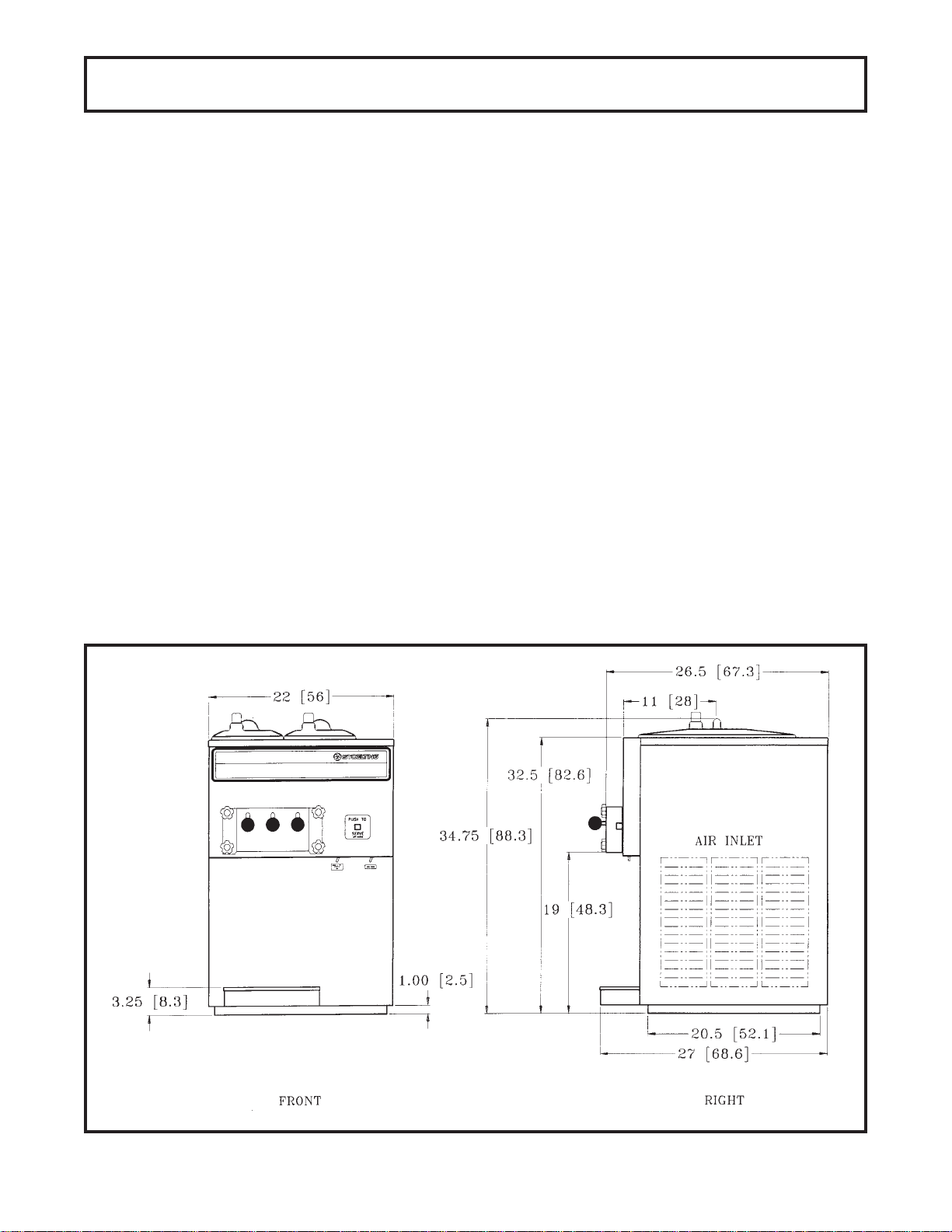
1.2 SPECIFICATIONS
Dimensions:
Width: 22" (56 cm)
Depth: 27" (68 cm)
Height: 34.75" (88 cm)
Weight: 370 lbs. (168 kg)
Electrical:
Description: Centura 131
Voltage AC: 1 Ph, 208-230V
Total Run. Amps: 10
Drive Motor: 1.5 HP
Compressor: 9960 BTU
Use 20 amp HACR circuit breaker.
Cooling
Air cooled requires minimum 3" air clearance on right and
left hand side. No clearance needed in the rear.
Hopper
3 Gallons (11.35 liters) each refrigerated and insulated.
Figure 1
C131 - Specifications
1
Page 8

2
Page 9
SECTION 2
INSTALLATION INSTRUCTIONS
2.1 SAFETY PRECAUTIONS
Do not attempt to operate the freezer until the safety
precautions and operating instructions in this manual are
read completely and are thoroughly understood.
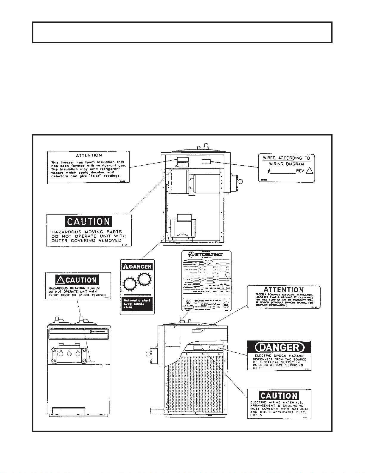
Take notice of all warning labels on the freezer (Fig. 2).
The labels have been put there to help maintain a safe
working environment. The labels have been designed to
withstand washing and cleaning. All labels must remain
legible for the life of the freezer.
Labels should be checked periodically to be sure they
can be recognized as warning labels.
If danger, warning or caution labels are needed, indicate
the part number, type of label, location of label, and
quantity required along with your address and mail to:
STOEL TING, INC.
A TTENTION: Marketing Services
502 Hwy . 67
Kiel, Wisconsin 53042-1600
Fig. 2. Warning Label Locations
3
Page 10
2.2 SHIPMENT AND TRANSIT
The freezer has been assembled, operated and inspected at the factory. Upon arrival at the final destination, the complete freezer must be checked for any
damage which may have occurred during transit.
D. Place the CLEAN-OFF-ON switch in the OFF posi-
tion.
E. Install the drip tray, covers and other miscellaneous
parts on the freezer.
With the method of packaging used, the freezer should
arrive in excellent condition. THE CARRIER IS RESPONSIBLE FOR ALL DAMAGE IN TRANSIT,
WHETHER VISIBLE OR CONCEALED. Do not pay the
freight bill until the freezer has been checked for damage. Have the carrier note any visible damage on the
freight bill.
If concealed damaged and/or shortage is found later,
advise the carrier within 10 days and request inspection.
The customer must place claim for damages and/or
shortages in shipment with the carrier. Stoelting, Inc.
cannot make any claims against the carrier.
2.3 FREEZER INST ALLATION
Installation of the freezer involves moving the freezer
close to its permanent location, removing all crating,
setting in place, assembling parts, and cleaning.
A. Uncrate the freezer.
B. Accurate leveling is necessary for correct drainage
of freezer barrel and to insure correct overrun. Place
a spirit level on top of the freezer at each corner to
check for level condition. If adjustment is necessary,
level the freezer by turning the bottom part of each
leg in or out. Then separate freezer base gasket and
install with the seam to the back and the flat to the
bottom (Fig. 3).
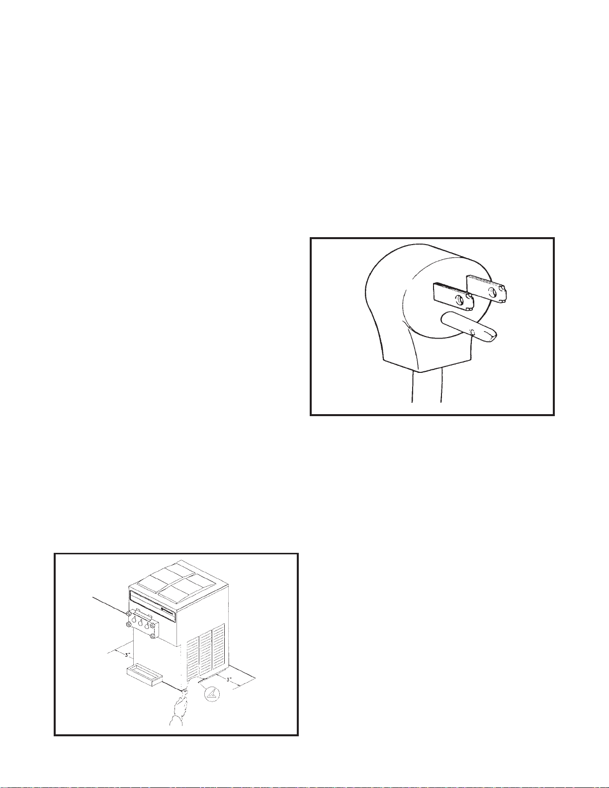
F. Connect the power cord. The plug is designed for 208
or 230 volt/20 amp duty. Check the nameplate on
your freezer for proper supply. The unit must be
connected to a properly grounded receptacle. The
electrical cord furnished as part of the freezer has a
three prong grounding type plug (Fig.4). The use of an
extension cord is not recommended. If one must be
used, use one with a size 12 gauge or heavier with a
ground wire. Do not use an adaptor to get around
grounding requirement.
Fig. 4. Grounding Plug
C. Air cooled freezers require correct ventilation. The
right side of the freezer is the air intake and must
have a 3" (7.5cm) clearance. Air discharges out of the
left side of the unit and must have 3" (7.5cm) clear-
ance. Do not obstruct the intake or discharge (Fig.3).
CAUTION
FAILURE TO PROVIDE ADEQUATE VENTILATION WILL
VOID WARRANTY!
CAUTION
DO NOT ALTER OR DEFORM PLUG IN ANY WAY!
2.4 FLOOR ST AND INSTALLATION
To install the C131 on the floor stand, follow the steps
outlined below.
1. Uncrate the floor stand and place in an uprightposition.
NOTE
Detailed instructions are included with each floor stand.
2. Place a spirit level across the top of the stand to
check for level condition, side to side and front to
back. If adjustment is necessary, level the stand by
turning the bottom part of each leg in or out, then
tighten the lock nut.
3. Remove the four legs from the freezer and replace
with the four leg adapters provided. Adapters must be
fully tightened to the freezer.
Fig. 3. Space and Ventilation Requirements
4
Page 11

4. Place the C131 freezer on the floor stand with the
front of the freezer to the door end of the stand.
Secure the freezer to the stand with the nuts and lock
washers provided. Then separate freezer base gasket
and install the seam to the back and the flat to the
bottom (Fig. 5).
Fig. 5. Floor Stand
5
Page 12

6
Page 13

SECTION 3
INITIAL SET-UP AND OPERATION
3.1 OPERA TOR'S SAFETY PRECAUTIONS
SAFE OPERATION IS NOT AN ACCIDENT; Observe
these rules:
A. Know the freezer. Read and understand the Operat-
ing Instructions.
B. Notice all warning labels on the freezer.
C. Wear proper clothing. Avoid loose fitting garments,
and remove watches, rings or jewelry which could
cause a serious accident.
D. Maintain a clean work area. Avoid accidents by
cleaning up the area and keeping it clean.
E. Stay alert at all times. Know which switch, push
button or control you are about to use and what effect
it is going to have.
F. Disconnect electrical cord for maintenance.
Never attempt to repair or perform maintenance on
the freezer until the main electrical power has been
disconnected.
G.Do not operate under unsafe operating condi
tions. Never operate the freezer if unusual or exces
sive noise or vibration occurs.
3.2 OPERA TION CONTROLS AND INDICA TORS
Before operating the freezer, it is required that the
operator know the function of each operating control.
Refer to Figure 6 for the location of the operating controls
on the freezer.
WARNING
THE CLEAN-OFF-ON SWITCH MUST BE PLACED IN
THE OFF POSITION WHEN DISASSEMBLING FOR
CLEANING OR SERVICING. THE FREEZER MUST BE
DISCONNECTED FROM ELECTRICAL SUPPLY BEFORE
REMOVING ANY ACCESS PANEL.
A. CLEAN-OFF-ON SWITCH
The CLEAN-OFF-ON switch is a three-position toggle
switch used to control the operation of the refrigeration system and auger. When the switch is placed in
the CLEAN position, the refrigeration system will be
off and the auger will rotate for cleaning.
When the switch is placed in the OFF position, the
refrigeration system and auger will not operate.
B. NIGHT-SERVE SWITCH
The NIGHT-SERVE switch is a two position toggle
switch. When the switch is placed in the SERVE
position, the auger and compressor will run until the
product is ready to serve. When the switch is in the
NIGHT position, the auger and compressor will run to
maintain a product in liquid form at a safe temperature.
C. SPIGOT SWITCH
The SPIGOT switch will automatically actuate the
auger drive and refrigeration systems when the spigot
is opened to dispense product. When the spigot is
closed, the drive motor and compressor will remain
“on” until the product in the barrel is ready to serve
again.
D. DRIVE MOTOR OVERLOAD
The internal drive motor overload will trip if the drive
motor is overloaded. It will reset after approximately
10-12 minutes. If the drive motor continues to trip,
refer to Section 4-Troubleshooting.
E. MIX LEVEL INDICATOR
The MIX LEVEL indicator has a red float designed to
alert the operator to a low mix condition. When the
red indicator is not visible, there is approximately one
gallon of mix left in the hopper. Refill hopper immediately.
NOTE
Failure to immediately refill hopper may result in operational problems.
F. DOOR INTERLOCK SWITCH
When the door is securely fastened, the freezer will
operate normally. When the door is removed, the drive
and compressor will not run.
3.3 SANITIZING
Sanitizing must be done after the freezer is clean and
just before the hopper is filled with mix. Sanitizing the
night before is not effective. However, you should
always clean the freezer and parts after using it.
WARNING
THE UNITED STATES DEPARTMENT OF AGRICULTURE AND THE FOOD AND DRUG ADMINISTRATION
REQUIRE THAT ALL CLEANING AND SANITIZING SOLUTIONS USED WITH FOOD PROCESSING EQUIPMENT BE CERTIFIED FOR THIS USE.
When the switch is placed in the ON position, the
refrigeration system and auger will operate automati-
cally. The switch should be placed in the ON position
for normal operation.
7
Page 14

Figure 6. Controls
8
Page 15

When sanitizing the freezer, refer to local sanitary
regulations for applicable codes and recommended
sanitizing products and procedures. The frequency of
sanitizing must comply with local health regulations.
Mix sanitizer according to manufacturer’s instructions to
provide a 100 parts per million strength solution. Mix
sanitizer in quantities of no less than 2 gallons (7.5
liters) of 120°F of water. Allow sanitizer to contact the
surfaces to be sanitized for 5 minutes. Any sanitizer
must be used only in accordance with the
manufacturer’s instructions.
CAUTION
PROLONGED CONTACT OF SANITIZER WITH FREEZER
MAY CAUSE CORROSION OF STAINLESS STEEL
PARTS.
In general, sanitizing may be conducted as follows:
A. Push the mix inlet regulator into hopper (Fig. 7).
Figure 7. Mix Inlet Regulator
B. Prepare 2 gallons (7.5 liters) of sanitizing solution
following manufacturer’s instructions. Pour into
hopper with mix inlet regulator in place (Fig.8).
Figure 8. Sanitizing Procedure
Figure 9. Sanitizing Hopper
C. Place the CLEAN-OFF-ON toggle switch in the
CLEAN position. Check for leaks.
D. Clean sides of hopper, mix inlet regulator and under-
side of hopper cover using a sanitized soft bristle
brush dipped in the sanitizing solution(Fig.9).
E. After five minutes, place a bucket under the spigot
and open spigot to drain sanitizing solution. Allow the
freezer barrel to drain completely (Fig.10). When
solution has drained, place the CLEAN-OFF-ON
switch in the OFF position.
Figure 10. Open Spigot and Drain Solution
9
Page 16

3.4 FREEZE DOWN AND OPERA TION
This section covers the recommended operating procedures to be followed for the safe operation of the freezer.
A. Sanitize just prior to use.
B. Place the CLEAN-OFF-ON switch in the OFF posi-
tion.
C. With spigots open, pour approximately 1 gallon (3.8
liters) of mix into the hopper. Allow the mix to flush
out about 8 ounces (0.23 liters) of sanitizing solution
and liquid mix. Close the spigot.
D. Fill hopper with approximately 3 gallons (11.4 liters) of
prechilled (40°F or 4°C) mix. The freezer barrel will
automatically fill until it is about half full.
CAUTION
DO NOT OVERFILL THE HOPPER. MIX LEVEL MUST
NOT BE HIGHER THAN 2 INCHES (5 CM) FROM THE TOP
OF TH E AIR INLET TUBE ON THE MIX INLET REGULATOR.
E. Place the NIGHT-SERVE switch in the SERVE
position.
F. Place the CLEAN-OFF-ON switch in the ON position.
After about 6 to 10 minutes the freezer will shut off
and the product will be ready to serve. Freeze down
time may be longer for some frozen diet dessert
mixes. High ambient temperatures may extend freeze
down time.
G. To dispense product, move the spigot handle up
(Fig.11). Close spigot completely after dispensing.
The freezer will run for a minimum of 50 seconds after
the spigot is closed.
H. The freezer is designed to dispense the product at a
reasonable draw rate. If the freezer is overdrawn, the
result is a soft product or a product that will not
dispense at all. If this should occur, allow the freezer
to run for approximately 30 seconds before dispensing additional product. After a while the operator will
sense or feel when the freezer is beginning to fall
behind, and will slow down on the rate of draw so as
not to exceed the capacity.
I. Do not operate the freezer if the mix level indicator
shows a low-mix condition (red indicator no longer
visible). A minimum of 1 gallon of mix should be kept
in the hopper at all times.
Figure 11. Dispensing Product
3.5 MIX INFORMA TION
Mix can vary considerably from one manufacturer to
another. Differences in the amount of butterfat content
and quantity and quality of other ingredients have a direct
bearing on the finished frozen product. A change in
freezer performance that cannot be explained by a
technical problem may be related to the mix.
When changing from one type of mix to another, you
may have to change the mix inlet regulator and/or control
settings. Please call your distributor for further information.
Proper product serving temperature varies from one
manufacturer’s mix to another. Mixes should provide a
satisfactory product in the 18° to 20°F (-7° to -6°C)
range.
When checking the temperature, stir the thermometer in
the frozen product to read the true temperature.
Mix does not improve with age. Old mix, or mix that has
been stored at too high a temperature, can result in a
finished product that is less than satisfactory in taste
and appearance. To retard bacteria growth in dairy based
mixes, the best storage temperature range is between
36° to 40°F (2.2° to 4.4°C).
Some products tend to foam more than others. If excess
foam should occur, skim the foam off with a sanitized
utensil and discard. Periodically stir the mix in the
hopper with a sanitized utensil.
J. For night operation, place the NIGHT-SERVE switch
to the NIGHT position. The product in the barrels will
return to a liquid state in approximately 4 hours.
10
Page 17

3.6 REMOVING MIX FROM THE FREEZER
To remove the mix from the freezer, refer to the following
steps:
A. Remove the mix inlet regulator from the hopper by
pulling straight up (Fig.12).
Figure 12. Removing Mix Inlet Regulator
D. Open the spigot to drain the water. Remember to
place a bucket or container under the spigot to catch
the water. When the water has drained, turn the
CLEAN-OFF-ON switch to the OFF position. Allow
the freezer barrel to drain completely.
E. Repeat steps A through D using a mild detergent
solution.
3.8 DISASSEMBL Y OF FREEZER P ARTS
CAUTION
PLACE THE CLEAN OFF-ON TOGGLE SWITCH IN THE
OFF POSITION BEFORE DISASSEMBLING FOR CLEANING OR SERVICING.
Inspection for worn or broken parts should be made at
every disassembly of the freezer for cleaning or other
purposes. All worn or broken parts should be replaced to
ensure safety to both the operator and the customer and
to maintain good freezer performance and a quality
product. Two normal wear areas are the auger flights and
front auger support bushing (Fig.13).
B. Place the CLEAN-OFF-ON switch in the CLEAN
position. Allow the mix to agitate in the freezer barrel
until the mix has become a liquid, about 5 minutes.
C. Drain the liquid mix by opening the spigot. A bucket
or container should be placed under the spigot to
catch the liquid mix.
D. Place the CLEAN-OFF-ON switch in the OFF posi-
tion.
3.7 CLEANING THE FREEZER
NOTE
The frequency of cleaning the freezer and freezer parts
must comply with local health regulations.
After the mix has been removed from the freezer, the
freezer must be cleaned. To clean the freezer, refer to
the following steps:
A. Close the spigot and fill the hopper with 2 gallons (7.5
liters) of cold tap water.
B. Place the CLEAN-OFF-ON switch in the CLEAN
position.
C. Allow the water to agitate for approximately five
minutes.
Figure 13. Auger Flight and Front
Auger Support Bushing Wear
Frequency of cleaning must comply with the local health
regulations. To disassemble the freezer, refer to the
following steps:
A. Remove the mix inlet regulator from the hopper by
pulling straight up.
B. Remove the front door by turning off the circular
knobs and then pulling the front door off the studs
(Fig.14).
C. Remove the rosette caps from the front door. Remove
the spigot handles by turning counter-clockwise, then
push the spigot body through the bottom of the front
door and remove spigot body (Fig.15).
NOTE
Machine will automatically shut off if left in CLEAN mode
for approximately 20 minutes.
D. Remove the front auger supports and bushings
(Fig.16).
11
Page 18

Figure 14. Removing Front Door Figure 16. Removing Front Auger Supports
Figure 17. Removing Auger Assemblies
Figure 15. Removing Spigot
E. Remove the auger assemblies from the freezer. Pull
the augers out of the freezer barrel slowly. As the
augers are being pulled out, carefully remove each of
the plastic flights with springs (Fig.17).
F. To avoid dropping rear seals, keep the rear of the
auger shafts tipped up once they are clear of the
freezer barrels.
G. Remove the rear seals.
H. Wipe socket lubricant from the drive end (rear) of the
auger with a cloth or paper towel.
Figure 18. Removing O-Ring
I. Remove all o-rings from parts by first wiping off the
lubricant using a clean paper towel. Then squeeze
the o-ring upward with a dry cloth (Fig.18). When a
loop is formed, roll out of the o-ring groove.
12
Page 19

WARNING
DO NOT USE ANY TYPE OF SHARP OBJECT TO REMOVE THE O-RINGS.
3.9 CLEANING THE FREEZER P ARTS
Place all loose parts in a pan or container and take to
the wash sink for cleaning. To clean freezer parts refer to
the following steps:
A. Place all parts in warm mild detergent water and
clean with brushes provided. Rinse all parts with
clean hot water.
CAUTION
DO NOT DAMAGE PARTS BY DROPPING OR ROUGH
HANDLING.
B. Wash the hopper and freezer barrel with warm
detergent water and brushes provided (Fig.19).
B. Place all parts in the sanitizing solution, then remove
and let air dry.
C. Using this sanitizing solution and the large barrel
brush provided, sanitize the barrel by dipping the
brush in the sanitizing solution and brushing the
barrel.
3.11 ASSEMBL Y OF FREEZER
To assemble the freezer parts, refer to the following
steps:
NOTE
Petrol-Gel sanitary lubricant or equivalent must be used
when lubrication of parts is specified.
NOTE
The United States Department of Agriculture and Food and
Drug Administration require that lubricants used on food
processing equipment be certified for this use. Use lubricants only in accordance with the manufacturer’s instructions.
A. Assemble all o-rings onto parts dry, without lubrica-
tion. Then apply a thin film of sanitary lubrication to
exposed surfaces of the o-rings. Apply a thin film of
sanitary lubricant to metal part of rear seal. Also
apply a thin film of sanitary lubricant inside the hole
of the front of the auger.
Figure 19. Washing Hopper and Freezer Barrel
C. Clean the rear seal surfaces from the inside of the
freezer barrel with warm detergent water.
NOTE
Clean the auger drive socket located inside the barrel at the
rear seal area. Use clean cloth or paper towel for this
purpose.
D. Clean the drip tray and insert with a soap solution.
Rinse with clean hot water.
3.10 SANITIZE FREEZER AND FREEZER P ARTS
A. Use a sanitizer mixed according to manufacturer’s
instructions to provide a 100 parts per million strength
solution. Mix sanitizer in quantities of no less than 2
gallons (7.5 liters) of 120°F water. Allow the sanitizer
to contact the surfaces to be sanitized for 5 minutes.
Any sanitizer must be used only in accordance with
the manufacturer’s instructions.
B. Assemble the rear seals onto the augers with the
large end to the rear. Be sure the o-ring is in place
before installing the rear seal.
C. Lubricate the auger drive hex (rear) with a small
amount of white socket lubricant (Fig.20). A small
container of socket lubricant is shipped with the
freezer.
D. Screw the springs onto the studs in plastic flights.
Springs must be screwed into the flights completely to provide compression (Fig.20).
Figure 20. Exploded View of Auger
13
Page 20

CAUTION
DO NOT PLACE THE MIX INLET REGULATOR INTO THE
HOPPER BEFORE INSTALLING THE AUGER.
NOTE
REFER TO 3-2, SECTION 3.3, for sanitizing the as-
sembled freezer before filling with mix.
E. Install the two plastic flights onto rear of the auger
and insert the auger assembly part way into freezer
barrel.
F. Install the third plastic flight, push the auger into the
freezer barrel and rotate slowly until the auger
engages the drive socket.
G. Install the auger support and bearing into the front of
the augers with one leg of the support at 9 o’clock.
H. Install the spigot bodies with springs and o-rings into
the front door from the bottom (Fig.21). Push straight
up until the spigots are in place.
3.12 ROUTINE CLEANING
To remove spilled or dried mix from the freezer exterior,
simply wash in the direction of the finish with warm
soapy water and wipe dry. Do not use highly abrasive
materials as they will mar the finish.
3.13 PREVENTIVE MAINTENANCE
It is recommended that a maintenance schedule be
followed to keep the freezer clean and operating properly.
WARNING
NEVER ATTEMPT TO REPAIR OR PERFORM MAINTENANCE ON FREEZER UNTIL THE MAIN ELECTRICAL
POWER HAS BEEN DISCONNECTED.
A. Daily
1.The exterior should be kept clean at all times to
preserve the lustre of the stainless steel. A mild
alkaline cleaner is recommended. Use a soft cloth
or sponge to apply the cleaner.
CAUTION
DO NOT USE ACID CLEANERS, STRONG CAUSTIC
COMPOUNDS OR ABRASIVE MATERIALS TO CLEAN
ANY PART OF THE FREEZER EXTERIOR OR PLASTIC
PARTS.
Figure 21. Removing Spigot
I. Install spigot handles by turning clockwise.
J. Install the front door on the freezer, then install the
circular knobs on the freezer studs.
CAUTION
HAND TIGHTEN THE CIRCULAR KNOBS EVENLY. DO
NOT OVERTIGHTEN KNOBS.
Look for the proper seal between the freezer barrel, oring, and front doors.
2.Run a sanitized brush down the air inlet regulator
tube (Fig. 22).
Figure 22. Sanitizing Air Inlet Regulator
B. Weekly
1.To check o-rings and rear seal for excessive wear
and replace if necessary.
14
Page 21

C. Monthly
CAUTION
FREEZERS THAT HAVE AIR COOLED CONDENSERS
MUST HAVE PROPER AIR CIRCULATION. DO NOT
PLACE RIGHT OR LEFT SIDE OF FREEZER ANY CLOSER
THAN 3 INCHES (7.5 CM) FROM ANY OBSTRUCTION.
FAILURE TO CLEAN THE CONDENSER FILTER ON A
REGULAR BASIS MAY RESULT IN SERIOUS FREEZER
DAMAGE AND COULD VOID FREEZER WARRANTY.
Remove the phillips head screw from the lower side of
the right side panel and pull the side panel down and
out.
Remove the condenser filter and clean in warm soapy
water. Rinse in clean water and shake dry, taking care
not to damage the filter in any way.
Replace the condenser filter and side panel.
3.14 EXTENDED STORAGE
Refer to the following steps for storage of the freezer over
any long period of shutdown time:
A. Turn the CLEAN-OFF-ON switch to the OFF position.
B. Disconnect (unplug) from the electrical supply
source.
C. With a warm water detergent, clean thoroughly all
parts that come in contact with the mix. Rinse in
clear water and dry all parts. Do not sanitize.
NOTE
Do not let the cleaning solution stand in the hopper or in the
freezer barrel during the shutdown period.
D. Remove, disassemble and clean the front door, mix
inlet regulator and auger parts. Place the auger flights
in a plastic bag with a moist paper towel to prevent
them from becoming brittle.
15
Page 22

16
Page 23

SECTION 4
TROUBLESHOOTING
melborPesuaCelbissoPydemeR
tonseodrezeerF
.nur
.deppirt
tonlliwrezeerF
.ffotuhs
.ytluaf
ootsitcudorP
.tfos
.F0001evoba
ootsitcudorP
.mrif
.ffosirezeerfotrewoP.1
ronwolbsirekaerbtiucricroesuF.2
.)nruttonlliwregua(pu-ezeerF.3
.ecalpnitonroodtnorF.4
.roodtnorfllatsnI.4
.wolootsignitteserusserP.1
si/tnemtsujdasdeenhctiwstogipS.2
.melborpnoitaregirfeR.3
.eruliaflortnocerusserP.4
.riagniloocfowolfeerfrofecapstnevoN.1
siresnednocgniretneerutarepmetriA.2
.ytridsiresnednoC.3
.hgihootgnitteserusserP.4
.nwodnekorberaximnisrezilibatS.5
.gnorwdelbmessasireguA.6
.melborpnoitaregirfeR.7
.reppohniximoN.1
.wolootsignitteserusserP.2
.ytluaflortnocerusserP.3
ecalperrotsujdA.2
.rezeerfmorf
.rezeerfotrewopylppuS.1
,seunitnocnoitidnocfI(.teserroecalpeR.2
).2ro1setonees
rofNOothctiwsNO-FFO-NAELCnruT.3
.tratserneht,setunim51
).ecivresrofrotubirtsidllaC(.tsujdaeR.1
).ecivresrof.tsidllaC(.metsyskcehC.3
).ecivresrofrotubirtsidllaC(.ecalpeR.4
ecapstnevfosehcni3fomuminimA.1
)3.2hpargarapeeS(.deriuqer
yawariatohtceridronoitacolegnahC.2
)7.3hpargarapeeS(.naelC.3
).ecivresrofrotubirtsidllaC(.tsujdaeR.4
elbmessa,ezitinas,naelc,ximevomeR.5
.ximhserfhtiwnwodezeerfdnaylreporp
ezitinas,elbmessaer,naelc,ximevomeR.6
.nwodezeerfdna
).ecivresrof.tsidllaC(.metsyskcehC.7
.ximhtiwreppohllIF.1
).ecivresrofrotubirtsidllaC(.tsujdaeR.2
).ecivresrofrotubirtsidllaC(.ecalpeR.3
.esnepsid
tlebevirD
rognippils
.gnilaeuqs
.nurrevowoL.gnorwdelbmessasireguA.1
tonseodtcudorP
.skaelroodtnorF.esoolerasbonkroodtnorF.1
.reppohniximoN.1
.deggulpsiebuttelniximroterubraC.2
gniebximrofdedeenroterubraclaicepS.3
.desu
.dedeecxegniebsirezeerffoyticapaC.4
.deppirtdaolrevorotomevirD.5
.eruliaftlebevirD.6
).nruttonlliwreguA(.pu-ezeerF.7
.tlebevirdnroW.1
).nruttonlliwreguA(.pu-ezeerF.2
.gnissimroterubraC.2
.gnissimgnir-oroterubraC.3
.dekcolbebutriaroterubraC.4
.nwodkaerbtcudorP.5
.detacirbultonerastraptogipS.2
.sgnir-otogipsnrowrodeppihC.3
.gnorwdellatsnitogipsrosgnir-O.4
rodekcinroodtnorfnielohtogipsrennI.5
.dehctarcs
).ecivresrof
.ximhtiwreppohlliF.1
.hsurbdezitinasllamsgnisu,gulpnU.2
.roterubraclaicepsredrO.3
.etarwardehtnopuwolS.4
.deloocnehwyllacitamotuateserlliW.5
rotubirtsidllac,seunitnocnoitidnocfI(
.tlebevirdecalpeR.6
rofFFOothctiwsNO-FFO-NAELCnruT.7
.tratserneht,setunim51
.tlebevirdecalpeR.1
rofFFOothctiwsNO-FFO-NAELCnruT.2
.tratserneht,setunim51
elbmessa,ezitinas,naelc,ximevomeR.1
.ximhserfhtiwnwodezeerfdnaylreporp
.roterubracecalpeR.2
.gnir-oroterubracecalpeR.3
.hsurbdezitinashtiwnaelC.4
.tcudorphserfhtiwrezeerflliF.5
.sbonknethgiT.1
.11.3hpargarapeeS.2
.sgnir-oecalpeR.3
.sgnir-okcehcdnatogipsevomeR.4
.roodtnorfecalpeR.5
tonlliwreppoH
.pmetximniatniam
).C7(F54woleb
.melborpnoitaregirfeR.1 rofrotubirtsidllaC(.metsyskcehC.1
).ecivres
17
Page 24

18
Page 25

SECTION 5
REPLACEMENT PARTS
5.1 HOW TO ORDER PARTS
To assure receipt of the proper replacement parts, supply
your dealer or distributor with the following information:
A. Model number of equipment.
O-RING IDENTIFICATION CHART
B. Serial number of model, stamped on nameplate
C. Part number, part name and quantity needed. Com-
mon part names and numbers are listed in this
manual.
Spigot
624598
5/8" ID x 1/8" CS
Carburetor
624667
1-1/8" ID x 1/8" CS
Spigot (Center)
624614
3/4" x 1.0" x 1/8"
Front Door
625133
4" ID x 3/16" CS
Spigot (Center)
624664
1-1/16" ID x 1-5/16" x 1/8"
Rear Seal
624678
1-1/8" ID x 3/16" CS
O-Rings are drawn to
Approximate Size
19
Page 26

Fig. 23. Electrical Components
20
Page 27

696725
Fig. 24. C131 - Exploded View
21
Page 28

Fig. 25. C131 Refrigeration System
22
Page 29

PARTS NOT SHOWN
146450 .................................. Bearing, Ball
146485 .................................. Bearing, Ball
162077 .................................. Blade Fan 16 in.
208135 .................................. Brush, Nylon 4 x 8 x 16 overall
208380 .................................. Brush, Nylon 1/4 x 14 x 3
208401 .................................. Brush, Nylon 1 x 3 x 10
208467 .................................. Brush, 3/8 x 1 x 5
232732 .................................. Cap Rosette 6 Point Plastic
236033 .................................. Cleaning Card C131
324105 .................................. Decal Caution - Elect. Shock
324106 .................................. Decal Caution - Wiring Material
324107 .................................. Decal Caution - Moving Parts
324141 .................................. Decal Caution - Rotating Blades
324208 .................................. Decal Refrig. Leak Check
324509 .................................. Decal Cleaning (SS & Shake)
324566 .................................. Decal Wired According To
324584 .................................. Decal Adequate Ventilation
324604 .................................. Decal Header Panel
324605 .................................. Decal Danger Automatic Start
342020 .................................. Drier
430119 ................................... Harness Cord 9 Ft.
490716 .................................. Leg Leveler Adjustable 3/8 - 16
508135 .................................. Lubricant - Petro-Gel 4 Oz.
513544 .................................. Owner's Manual C131
624598 .................................. O-Ring - Outer Spigots
624614 .................................. O-Ring - Center Spigot (Middle)
624644 .................................. O-Ring - Center Spigot
624678 .................................. O-Ring - Rear Seal
625133 .................................. O-Ring - Front Door
667882 .................................. Seal, Shaft
694255 .................................. Spring Comp
718766 .................................. Switch, Limit
744058 .................................. Transformer 208/240V Primary
1106373 ................................. Lubricant Spline
2119012 ................................. Indicator Assy. Liquid Level
3170767 ................................ Panel, Side
4170766 ................................ Upper Front Panel
23
Page 30

24
Page 31

WARRANTY
SOFT SERVE / SHAKE FREEZERS
1. Scope:
Stoelting, LLC warrants to the first user (the “Buyer”) that the freezer cylinders, hoppers, compressors,
drive motors, speed reducers, auger and auger flights of Stoelting soft serve / shake freezers will be free
from defects in materials and workmanship under normal use and proper maintenance appearing within
five (5) years, and that all other components of such equipment manufactured by Stoelting will be free from
defects in material and workmanship under normal use and proper maintenance appearing within twelve
(12) months after the date that such equipment is originally installed.
2. Disclaimer of Other Warranties:
THIS WARRANTY IS EXCLUSIVE; AND STOELTING HEREBY DISCLAIMS ANY IMPLIED
WARRANTY OF MERCHANTABILITY OR FITNESS FOR PARTICULAR PURPOSE.
3. Remedies:
Stoelting’s sole obligations, and Buyer’s sole remedies, for any breach of this warranty shall be the repair
or (at Stoelting’s option) replacement of the affected component at Stoelting’s plant in Kiel, Wisconsin, or
(again, at Stoelting’s option) refund of the purchase price of the affected equipment, and, during the first
twelve (12) months of the warranty period, deinstallation/reinstallation of the affected component from/into
the equipment. Those obligations/remedies are subject to the conditions that Buyer (a) signs and returns
to Stoelting, upon installation, the Checklist/Warranty Registration Card for the affected equipment, (b)
gives Stoelting prompt written notice of any claimed breach of warranty within the applicable warranty
period, and (c) delivers the affected equipment to Stoelting or its designated service location, in its original
packaging/crating, also within that period. Buyer shall bear the cost and risk of shipping to and from
Stoelting’s plant or designated service location.
4. Exclusions and Limitations:
This warranty does not extend to parts, sometimes called “wear parts”, which are generally expected to
deteriorate and to require replacement as equipment is used, including as examples but not intended to
be limited to o-rings, auger seals, auger support bushings and drive belts. All such parts are sold
AS IS.
Further, Stoelting shall not be responsible to provide any remedy under this warranty with respect to any
component that fails by reason of negligence, abnormal use, misuse or abuse, use with parts or equipment
not manufactured or supplied by Stoelting, or damage in transit.
THE REMEDIES SET FORTH IN THIS WARRANTY SHALL BE THE SOLE LIABILITY
STOELTING AND THE EXCLUSIVE REMEDY OF BUYER WITH RESPECT TO EQUIPMENT
SUPPLIED BY STOELTING; AND IN NO EVENT SHALL STOELTING BE LIABLE FOR ANY
INCIDENTAL OR CONSEQUENTIAL DAMAGES, WHETHER FOR BREACH OF
WARRANTY OR OTHER CONTRACT BREACH, NEGLIGENCE OR OTHER TORT, OR ON
ANY STRICT LIABILITY THEORY.
 Loading...