

UM2559
User manual
Getting started with the X-NUCLEO-IKS01A3 motion MEMS and environmental
sensor expansion board for STM32 Nucleo
Introduction
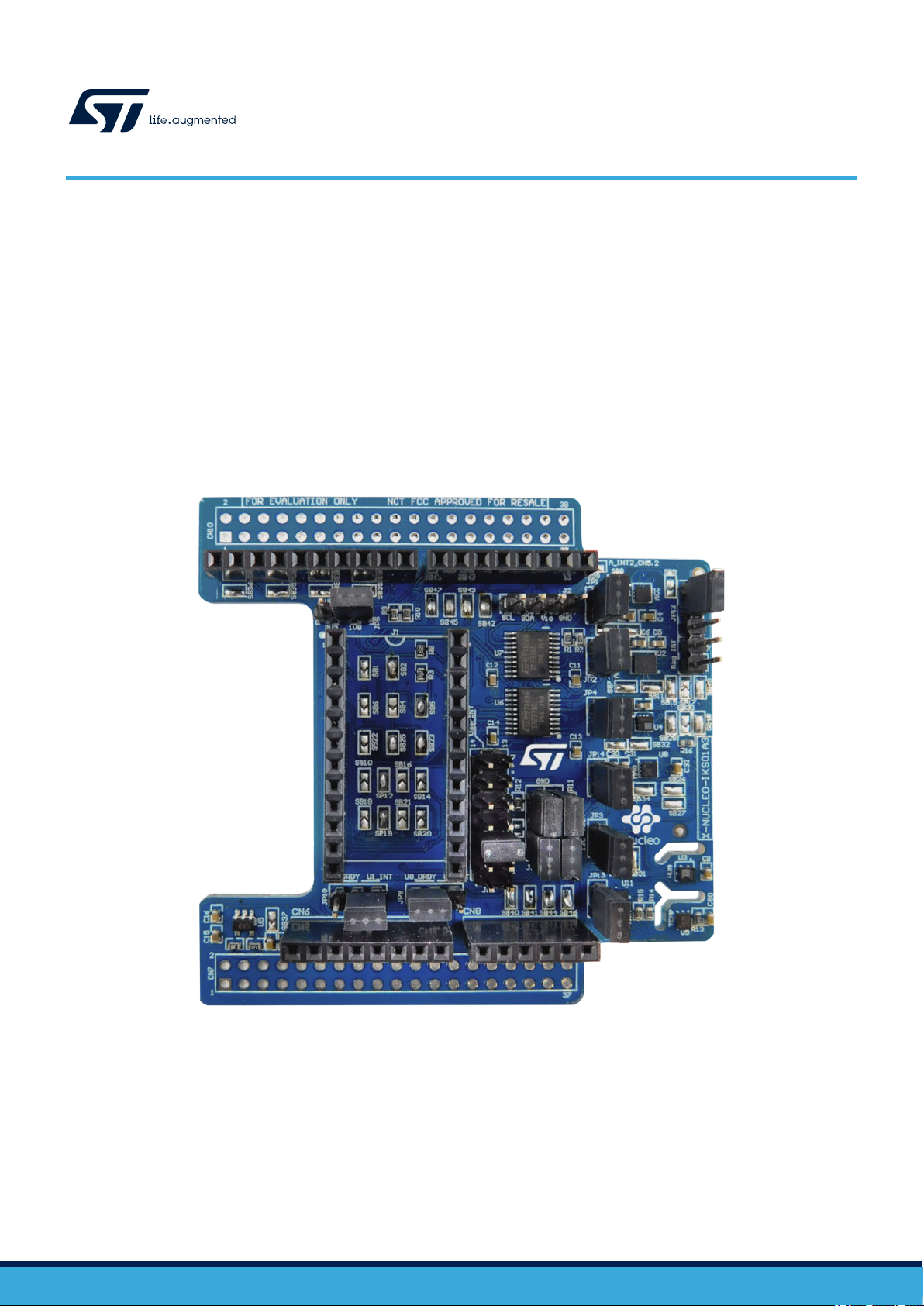
The X-NUCLEO-IKS01A3 is a motion MEMS and environmental sensor evaluation board system.
It is compatible with the Arduino UNO R3 connector layout and features the LSM6DSO 3-axis accelerometer + 3-axis
gyroscope, the LIS2MDL
sensor, the LPS22HH pressure sensor, and the STTS751 temperature sensor.
The X-NUCLEO-IKS01A3 interfaces with the STM32 microcontroller via the I²C pin, and it is possible to change the default I²C
port.
3-axis magnetometer, the LIS2DW12 3-axis accelerometer, the HTS221 humidity and temperature
Figure 1. X-NUCLEO-IKS01A3 expansion board
UM2559 - Rev 3 - September 2020
For further information contact your local STMicroelectronics sales of
fice.
www.st.com
1 Getting started
1.1 Hardware requirements
UM2559
Getting started
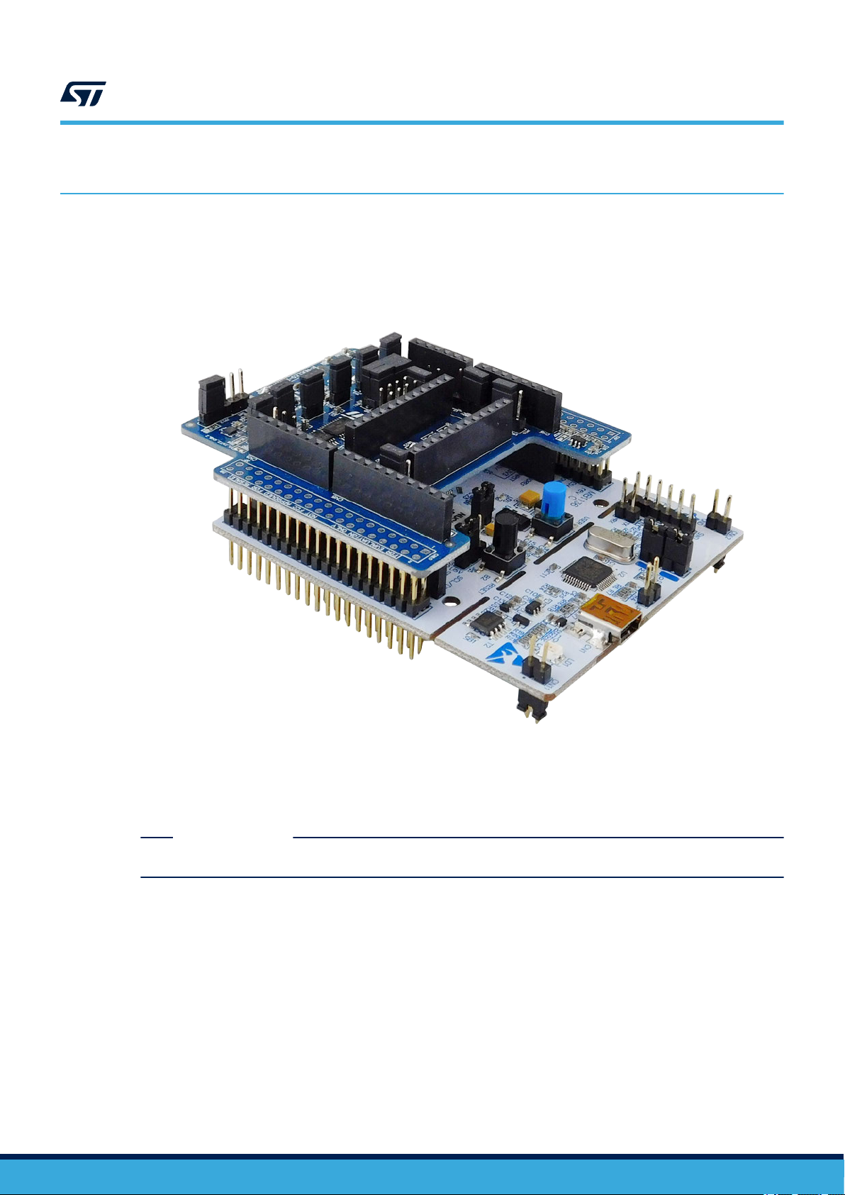
The X-NUCLEO-IKS01A3 is designed to be used with STM32 Nucleo boards (visit www
information).
Figure 2. X-NUCLEO-IKS01A3 plugged on an STM32 Nucleo board
.st.com for further
The X-NUCLEO-IKS01A3 must be connected on the matching pins of any STM32 Nucleo board with the Arduino
UNO R3 connector
Note: X-NUCLEO-IKS01A3 components are ESD sensitive and, as the board has male/female pass-through
connectors, it is important to handle it with care to avoid bending or damaging the pins.
.
RELATED LINKS
See the X-CUBE-MEMS1 product page for firmware and related documentation
UM2559 - Rev 3
page 2/17

2 System requirements
To complete the system setup, you need:
•
a Windows® (7, 8, 10) PC
• a USB type A to mini-B USB cable to connect the STM32 Nucleo to the PC
• board firmware and software package (X-CUBE-MEMS1) installed on the user PC
UM2559
System requirements
UM2559 - Rev 3
page 3/17
3 Hardware description
The board lets you test the functionality of the motion MEMS accelerometer, gyroscope and magnetometer, and
environmental humidity
It also allows all LSM6DSO sensor hub function testing.
The board features:
• Operating range: 3.3 V, 250 mA
• LSM6DSO: MEMS 3D accelerometer (±2/±4/±8/±16 g) + 3D gyroscope (±125/±250/±500/±1000/±2000 dps)
• LIS2MDL: MEMS 3D magnetometer (±50 gauss)
• LIS2DW12: MEMS 3D accelerometer (±2/±4/±8/±16 g)
• LPS22HH: MEMS pressure sensor, 260-1260 hPa absolute digital output barometer
• HTS221: capacitive digital relative humidity and temperature
• STTS751: Temperature sensor (–40 °C to +125 °C)
• DIL 24-pin socket available for additional MEMS adapters and other sensors
• Free comprehensive development firmware library and example for all sensors compatible with STM32Cube
firmware
• I²C sensor hub features on LSM6DSO available
• Compatible with STM32 Nucleo boards
• Equipped with Arduino UNO R3 connector
• RoHS compliant
• WEEE compliant
Each device has a separate power supply to allow power consumption measurement of every sensor.
The expansion board is power supply compatible with STM32 Nucleo boards: it mounts an LDO to generate 1.8 V
for all the MEMS sensors except for the STTS751, which is supplied by a separate LDO generating 2.5 V.
All signals between the sensors and the main board are translated by a level shifter.
, temperature and pressure sensors, via the I²C communication bus.
UM2559
Hardware description
3.1 Default solder bridge configuration
The user can configure several aspects of the X-NUCLEO-IKS01A3 through several solder bridges which can be
left open (not mounted) or closed (mounted) to configure dif
Table 1. Default solder bridge default configuration (device to I²C bus connection)
Device BUS Solder bridge (default) Solder bridge (not mounted)
LIS2DW12 I²C2 SB3, SB13 -
LSM6DSO I²C2 SB7, SB11 -
HTS221 I²C1 SB24, SB31 -
LPS22HH I²C1 SB29, SB32 -
STTS751 I²C1 SB26, SB27 -
LIS2MDL I²C1 SB33, SB34 -
STM32 Nucleo I²C2 SB35, SB36 -
DIL24 Adapter I²C1 SB12, SB19 SB1, SB4, SB6, SB10, SB14, SB16, SB18, SB20, SB21, SB22
*DIL24 Adapter I²C2 SB16, SB21 SB1, SB4, SB6, SB10, SB14, SB12, SB18, SB20, SB19, SB22
*DIL24 Adapter I²Cx SB14, SB20 SB1, SB4, SB6, SB10, SB12, SB16, SB18, SB19, SB21, SB22
ferent hardware settings.
UM2559 - Rev 3
page 4/17
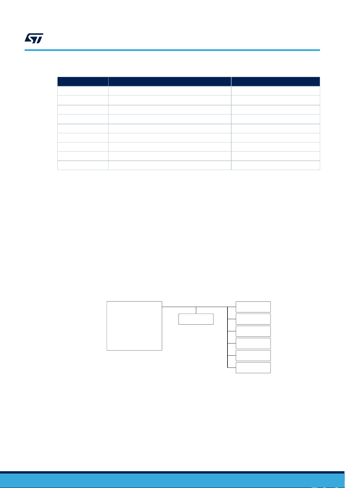
Table 2. Device I²C address
STM32 Nucleo
board
Arduino UNO R3
ST morpho
LSM6DSO
LIS2DW12 LIS2MDL
LPS22HH
HTS221
STTS751
DIL24
I²C2
I²C1
Device Solder bridge (non default) I²C address default
LIS2DW12 SB8 32h
LIS2DW12
LSM6DSO SB15 D6h
LSM6DSO
LIS2MDL - 3C
STTS751 - 94h
LPS22HB SB13 BAh
LPS22HB SB14 B8h
HTS221 - BEh
1.
not mounted by default
SB9
SB17
(1)
(1)
30h
D4h
Note: Other SBs mounted by default are SB40 to SB49 (STM32 Nucleo GPIO INT), SB23, SB25, SB39
Other SBs not mounted by default are SB38, SB37, SB50
UM2559
Block diagram
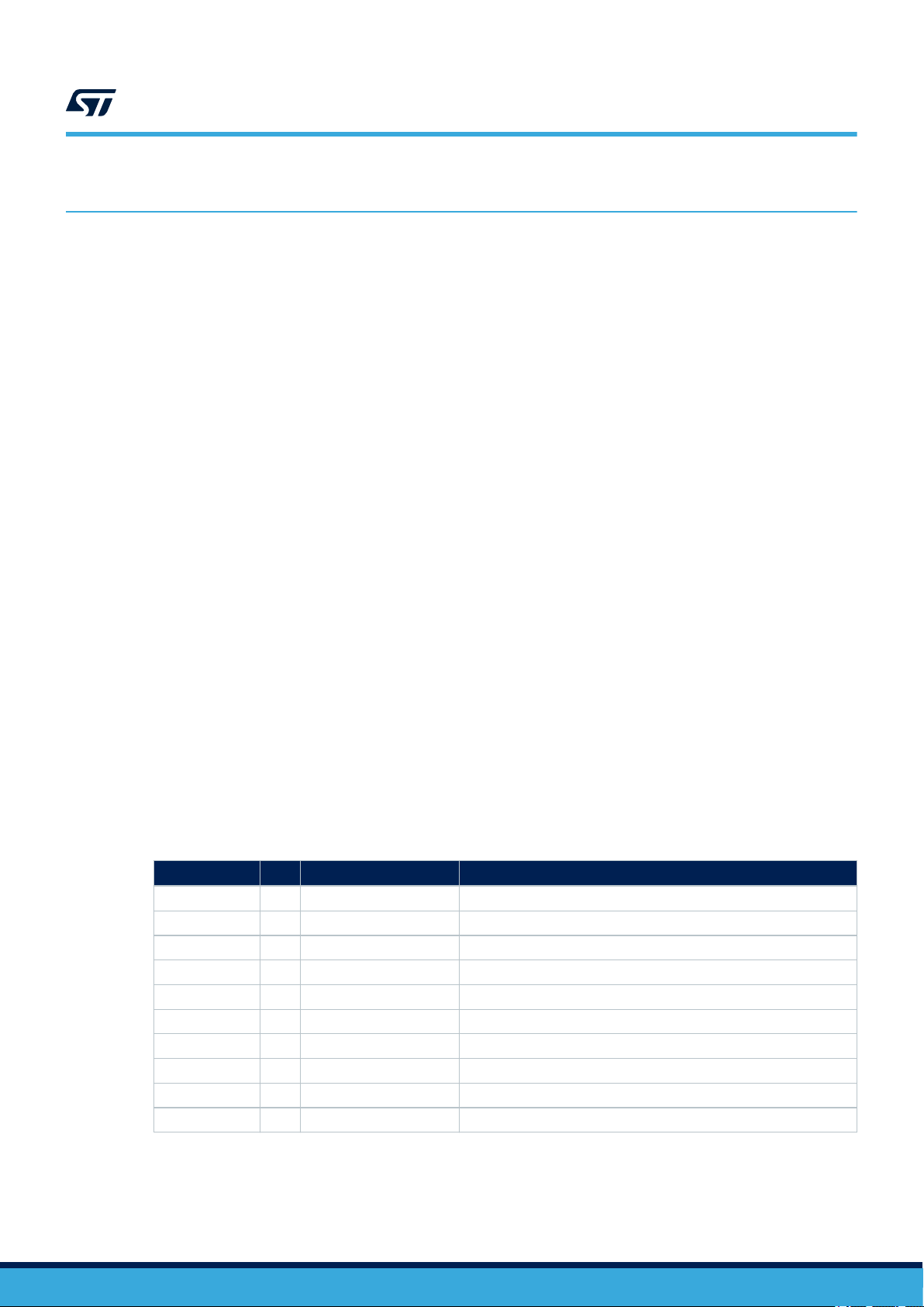
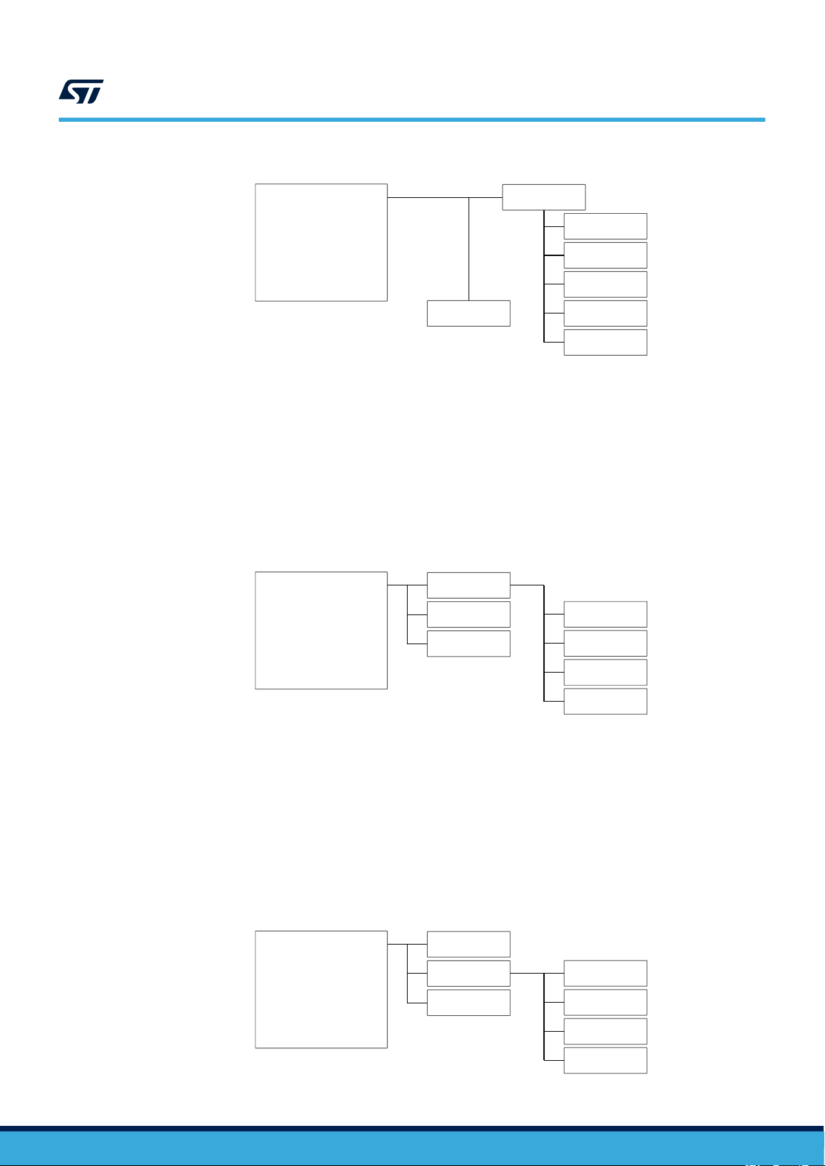
3.2 Block diagram
The LSM6DSO has an I²C sensor hub which allows it to behave as the I²C master for other slave devices
connected via an I²C
the LSM6DSO sensor hub.
Mode 1: standard I²C bus connection (all sensors)
In standard I²C mode, all devices are connected to an external main board via the same I²C bus.
The board configuration is:
• JP7: 1-2, 3-4 (I²C1 = I²C2, I²Cx=GND)
• JP8: 1-2, 3-4 (I²C1 = I²C2, I²Cx=GND)
bus. Various configurations are possible for different I²C bus connections with or without
aux
Figure 3. X-NUCLEO-IKS01A3 standard I²C
UM2559 - Rev 3
Mode 2: LSM6DSO I²C sensor hub (all sensors)
In this sensor hub I²C mode, the LSM6DSO is connected to an external main board by an I²C bus; all other
devices except LIS2DW12 are slaves connected to LSM6DSO via I²C
aux
.
The board configuration is:
•
JP7: 2-3 (I²C1 = I²Cx)
• JP8: 2-3 (I²C1 = I²Cx)
page 5/17
STM32 Nucleo
board
Arduino UNO R3
ST morpho
LSM6DSO
LIS2DW12
LIS2MDL
LPS22HH
HTS221
STTS751
DIL24
I²C2
I²C1
I²Caux
(sensor Hub)
STM32 Nucleo
board
Arduino UNO R3
ST morpho
LSM6DSO
LIS2DW12
LIS2MDL
LPS22HH
HTS221
STTS751
DIL24
I²C2
I²C1
I²Caux
(sensor Hub)
STM32 Nucleo
board
Arduino UNO R3
ST morpho
LSM6DSO
LIS2DW12
LIS2MDL
LPS22HH
HTS221
STTS751
DIL24
I²C2
I²C1
I²Caux
(sensor Hub)
UM2559
Block diagram
Figure 4. X-NUCLEO-IKS01A3 LSM6DSO I²C sensor hub
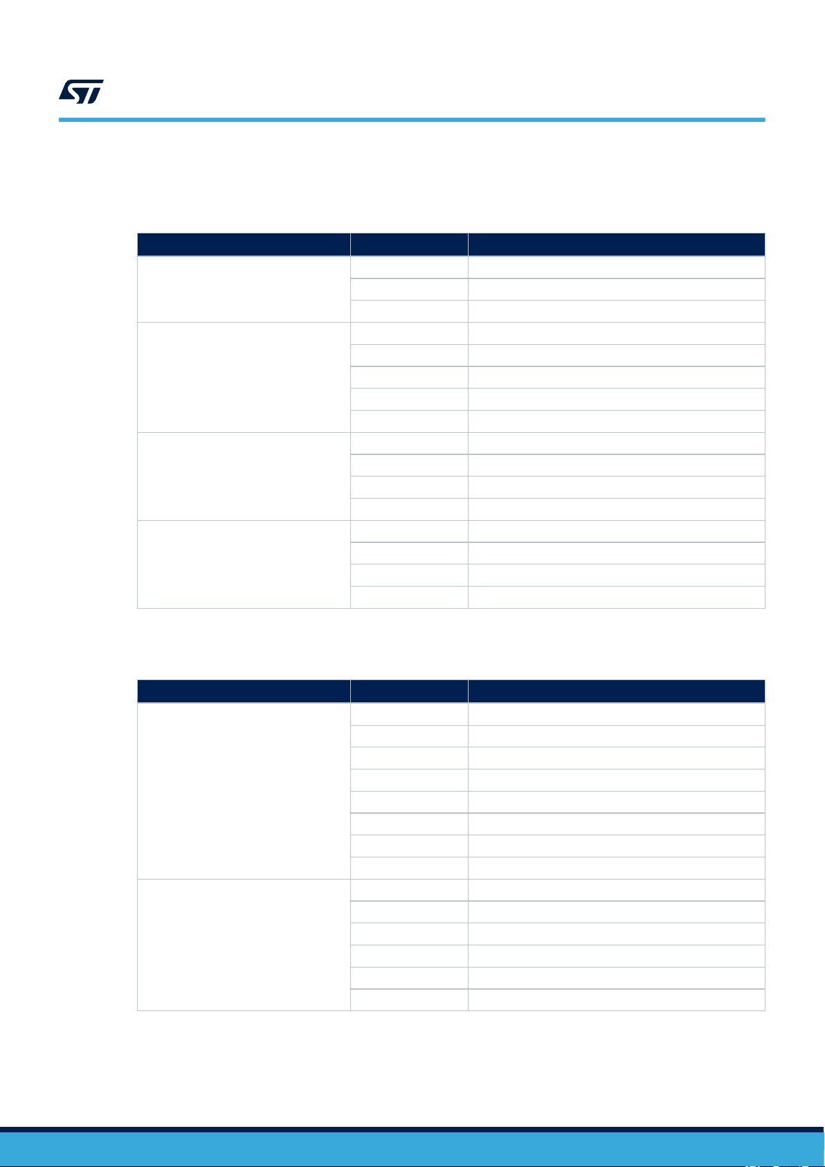
Mode 3: DIL24 plus LSM6DSO I²C sensor hub (all sensors, not DIL24)
In this sensor hub I²C mode, the LSM6DSO and the DIL24 adapter are connected to an external main board by
an I²C bus; all other devices except LIS2DW12 are slaves of the LSM6DSO via I²C
The board configuration is:
•
JP7: 2-3 (I²C1 = I²Cx)
• JP8: 2-3 (I²C1 = I²Cx)
DIL24 adapter (to I²C2): SB16, SB21
Not mounted: SB6, SB10, SB12, SB14, SB18, SB19, SB20, SB22
aux
.
Figure 5. X-NUCLEO-IKS01A3 DIL24, LSM6DSO I²C sensor hub (all sensors)
Mode 4: LSM6DSO plus DIL24 I²C sensor hub (all sensors)
In this sensor hub I²C mode, the LSM6DSO and the DIL24 adapter are connected to an external main board by
an I²C bus; all other devices except LIS2DW12 are slaves of the DIL24 adapter via I²C
The board configuration is:
JP7: 2-3 (I²C1 = I²Cx)
•
• JP8: 2-3 (I²C1 = I²Cx)
DIL24 adapter (to I²C2): SB16 SB21
Not mounted: SB6, SB10, SB12, SB14, SB18, SB19, SB20, SB22
Figure 6. X-NUCLEO-IKS01A3 LSM6DSO, DIL24, I²C sensor hub (all sensors)
aux
.
UM2559 - Rev 3
page 6/17

STM32 Nucleo
board
Arduino UNO R3
ST morpho
LSM6DSO
LIS2DW12
LIS2MDL
LPS22HH
HTS221
STTS751
DIL24
I²C2
I²C1
I²Caux
(sensor Hub)
UM2559
Sensor I²C address selection
Mode 5: LSM6DSO plus I²C sensor hub DIL24
In this sensor hub I²C mode, the LSM6DSO and other sensors are connected to an external main board via an I²C
bus; the DIL24 adapter is a slave of the LSM6DSO via I²C
The board configuration is:
•
JP7: 1-2 (I²C1 = I²Cx)
• JP8: 1-2 (I²C1 = I²Cx)
DIL24 adapter (to I²Cx): SB14, SB20
Not mounted: SB6, SB10, SB12, SB16, SB18, SB19, SB21, SB22
Figure 7. X-NUCLEO-IKS01A3 LSM6DSO plus sensor hub DIL24
aux
.
3.3 Sensor I²C address selection
Most sensors allow I²C address LSB selection by pulling the SD0 pin low or high. The board has solder bridges to
control SD0 level.
able 3. Solder bridges for SD0 level control and I²C address
T
Sensor SD0 high SD0 low
STTS751 (U9) ADD= 94h
LIS2DW12(U1) SB8 ADD=32h SB9 ADD=30h
LSM6DSO (U2) SB15 ADD=D6h SB17 ADD=D4h
LPS22HH (U4) SB28 ADD=BAh SB30 ADD=B8h
LIS2MDL (U8) ADD =3Ch ADD =3Ch
HTS221 (U3) ADD= BEh ADD= BEh
DIL24 Adapter (J1) SB1/SB2 SB4/SB5
3.4 Sensor current consumption measurement
The X-NUCLEO-IKS01A3 expansion board is equipped with jumpers which allow separate current consumption
measurement for each sensor
To measure current consumption, connect an ammeter to the appropriate jumper.
Note: As the sensors have very low current consumption, you should set a suitable range and use an ammeter with
low burden voltage.
.
UM2559 - Rev 3
page 7/17
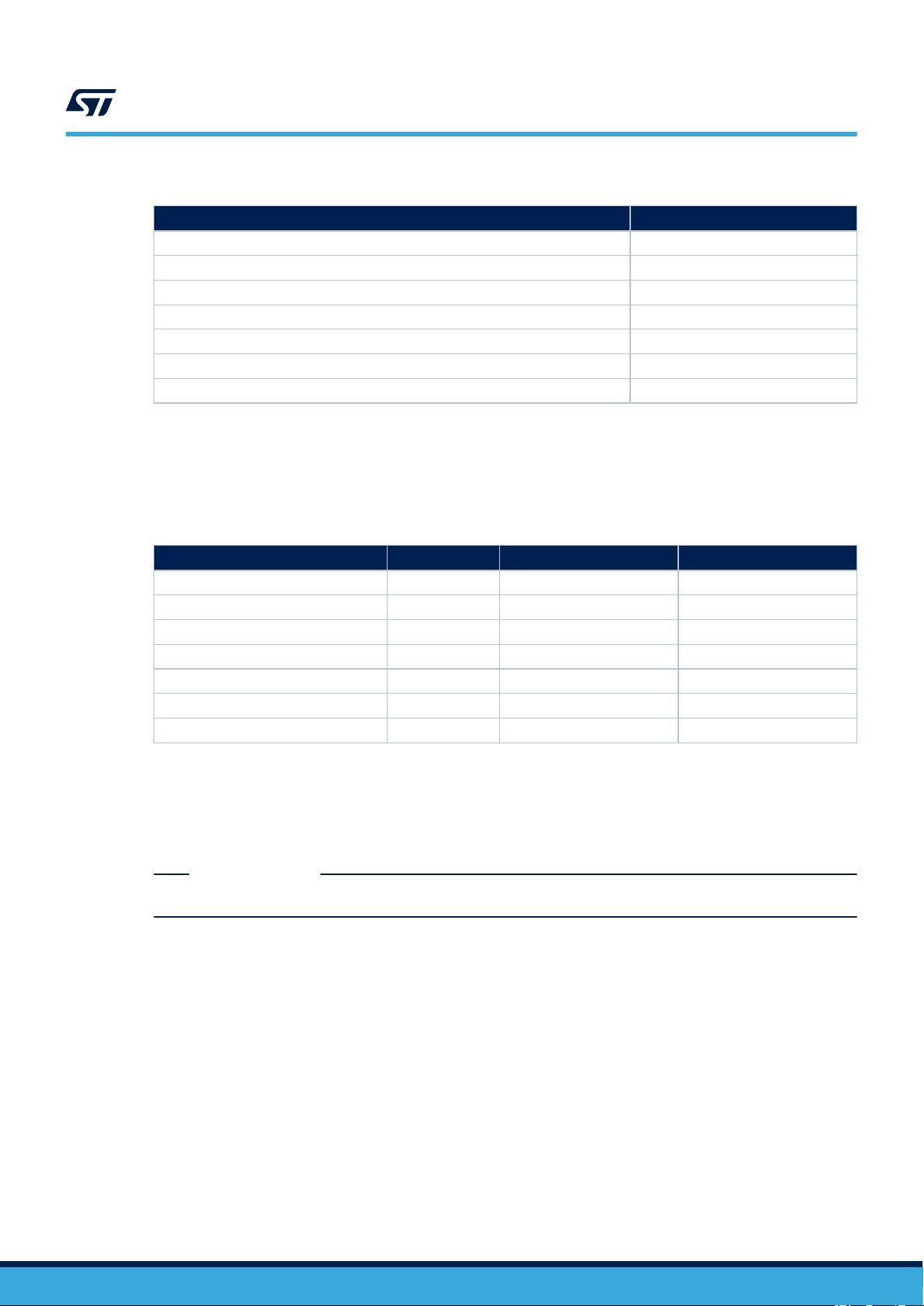
Table 4. Jumpers for current consumption measurement
3.5 Sensor disconnection
To disconnect a sensor, you should disconnect the I²C bus as well as the power supply. See the table below for
the relevant jumpers and solder bridges.
T
able 5. Link between sensors, jumpers and I²C solder bridges
UM2559
Sensor disconnection
Sensor Jumper
LIS2MDL (U8) JP14
LSM6DSO (U2) JP11
HTS221 (U3) JP3
LPS22HH (U4) JP4
STTS751 (U9) JP13
LIS2DW12 (U1) JP1
DIL24 Adapter (J1) JP5
Sensor Power SDA SCL
LIS2MDL (U8) JP14 SB34 SB33
LSM6DSO (U2) JP11 SB11 SB7
HTS221 (U3) JP3 SB24 SB31
LIS2DW12 (U1) JP1 SB3 SB13
STTS751 (U9) JP13 SB26 SB27
LPS22HH (U4) JP4 SB32 SB29
DIL24 adapter JP5 SB12,14,16 SB19,20,21
3.6 Adapter board for DIL24 socket
An additional sensor can be connected as an adapter board to J1 DIL24 socket.
As there are a few dif
the JP6 header.
RELATED LINKS
Please visit the ST website to find other available sensors
ferent interrupt signal assignments for DIL24 pins, the appropriate pin can be selected using
UM2559 - Rev 3
page 8/17
3.7 Connectors
Connector
unlisted pins are not connected.
1.
CN5
CN6
CN8
CN9
Table 6. Arduino R3 UNO connectors
(1)
Pin
7 GND
9 I²C SDA
10 I²C SCL
2 3.3 V
4 3.3 V
6 GND
7 GND
8 N.C.[FT1]
3 LIS2MDL DRDY
4 LIS2DW12 INT
5 STTS751 INT
6 INT1 (DIL24)
3 USER INT
5 LSM6DSO INT1
6 LSM6DSO INT2
7 LPS22HH INT1
UM2559
Connectors
Signal
Connector
CN7
CN10
The unlisted pins are not connected.
1.
Table 7. ST morpho connectors
(1)
Pin
12 3.3 V
16 3.3 V
20 GND
22 GND
32 LIS2MDL DRDY
34 LIS2MDL DRDY
36 STTS751 INT
38 INT1 (DIL24)
3 I²C SCL
5 I²C SDA
25 LPS22HH INT1
27 LSM6DSO INT2
29 LSM6DSO INT1
33 USER INT
Signal
UM2559 - Rev 3
page 9/17

4 Bill of materials
Item Quantity Reference Part / value Description Manufacturer Part number
1 4 C3, C6, C15, C31 10µF
C4, C5, C8, C9,
C1
2 12
3 1 C18 2.2µF
4 1 C32 220nF
5 4
6 1 J1 - DIL24 Socket MULTICOMP 2212S-12SG-85
7 7
8 4
9 1 JP6 2x7 Header
10 2 JP7, JP8 - Header + 2 shunts
11 10
12 2 R3, R8 2k2 RES 0603 ±1% 1/16 W MULTICOMP MC0063W060312K2
13 1 R6 12k RES 0603 ±1% 1/16 W MULTICOMP MC0063W0603512K
14 1 R7 15k RES 0603 ±1% 1/16 W MULTICOMP MC0063W0603515K
15 1 R13 7K5 RES 0603 ±0.5% 1/16 W SUSUMU RR0816P-752-D
16 34
17 1 U1 LIS2DW12
18 1 U2 LSM6DSO
1, C12, C13,
C14, C16, C17,
C30, C80
CN5, CN6, CN8,
CN9
JP1, JP2, JP3,
JP4, JP1
JP14
JP5, JP9, JP10,
JP12
R1, R2, R9, R10,
R1
1, R12, R14,
R15, R16, R17
SB2, SB3, SB5,
SB7, SB8, SB1
SB12, SB13,
SB15, SB19,
SB23, SB24,
SB25, SB26,
SB27, SB28,
SB29, SB31,
SB32, SB33,
SB34, SB35,
SB36, SB39,
SB40, SB41,
SB42, SB43,
SB44, SB45,
SB46, SB47,
SB48, SB49
1, JP13,
Table 8. X-NUCLEO-IKS01A3 bill of materials
CAP CER 0603 6.3 V
X5R ±20%
100nF
10x1, 8x1, 6x1,
8x1
2x1 Header + Shunt HARWIN M20-9990246
- Header + Shunt
4k7 RES 0603 ±1% 1/16 W MULTICOMP MC0063W060314K7
1,
- Solder Bridge - -
CAP CER 0603 25 V X7R
±10%
CAP CER 0603 25 V X5R
±10%
CAP CER 0603 25 V X7R
10%
Headers 4UCON -
3-axis MEMS
accelerometer
iNEMO 6DoF inertial
measurement unit
UM2559
Bill of materials
MULTICOMP MC0603X106M6R3CT
MULTICOMP MC0603B104K250CT
MULTICOMP MC0603X225K100CT
KEMET C0603X224K4RACTU
Generic
Components
Generic
Components
Generic
Components
ST LIS2DW12
ST LSM6DSO
2211S-03G
61301421121
2211S-04G
UM2559 - Rev 3
page 10/17

UM2559
Bill of materials
Item Quantity Reference Part / value Description Manufacturer Part number
19 1 U3 HTS221
20 1 U4 LPS22HH
21 1 U5 LDK130M-R
22 2 U6, U7 ST2378E
23 1 U8 LIS2MDL
24 1 U9 STTS751
25 1 U10 NTS0104GU12
26 1 U11 LDK120PU25
Digital sensor for relative
humidity and temperature
MEMS nano pressure
sensor
300 mA low quiescent
current very low noise
LDO
8-Bit Level Translator with
15kV ESD Protection
Magnetic sensor digital
output 50 gauss
2.25 V low-voltage local
digital temperature
sensor
IC TXRX TRANSLATING
2BIT 8XSON
200 mA low quiescent
current very low noise
LDO
ST HTS221
ST LPS22HH
ST LDK130M-R
ST ST2378E
ST LIS2MDL
ST STTS751
NXP NTS0104GU12
ST LDK120PU25R
UM2559 - Rev 3
page 11/17

1
2
3
4
JP7
M_INT_Pin16
M_INT2
M_INT1
M_INT_Pin17
GND
DIL24 Socket for Adap ter Boar dAcceleromet er LIS2DW12
Acceleromet er + Gyr oscope
M_INT_Pin24
M_SA0/DRDY
M_SA0/DEN
LSM6DSO
GND
LIS2DW12_INT
GND
GND
GND
M_INT2_O
M_INT1_O
USER_INT_O
USER_INT M_INT_Pin16
M_INT_Pin17
Ard uino & Mor pho Conn ectors
Morpho connector
3V3
1
2
3
4
5
6
7
8
CN6
1
2
3
4
5
6
CN8
1 2
3 4
5 6
7 8
9 10
11 12
13 14
15 16
17 18
19 20
21 22
23 24
25 26
27 28
29 30
31 32
33 34
35 36
3837
Header 19x2
CN7
DNM
Arduino ConnectorArduino Connector
Morpho connector
1
2
3
4
5
6
7
8
9
10
CN5
1
2
3
4
5
6
7
8
CN9
1 2
3 4
5 6
7 8
9 10
11 12
13 14
15 16
17 18
19 20
21 22
23 24
25 26
27 28
29 30
31 32
33 34
35 36
3837
Header 19x2
CN10
DNM
Arduino ConnectorArduino Connector
HTS2_DRDY
LPS22HH_INT
Relative hu midity + Tem perat ure
Pr essur e sesnsor LPS22HH
HTS221
CS
6
DRDY
3
SCL
2
1V8
1
SDA
4
GND
5
HTS221
U3
GND
GND
100nF
C9
SB3
SB7
SB11
SB24
SB31
SB32
4k7
R1
2k2
R3
4k7
R2
SB35
SB36
SB41
SB40
SB47
SB45
SB43
SB42
SB44
SB46
SB2
SB5
I2C ADDw = D6hSB15
I2C ADDw = BAh
SB28
SDO1SDx2SCx3INT1
4
1V8IO
5
GND
6
GND
7
1V8
8
INT2
9
OCS
10
NC
11
CS
12
SCL
13
SDA
14
LSM6DSO
U2
SB14
DNM
SB20
DNM
SCx
SDx
SCx
SDx
GND
SCL
SDA
GND
10
Vcc
20
VL
1
I/O_Vcc89I/O_VL8
12
I/O_VL7
8
I/O_VL6
14
I/O_VL5
6
I/O_VL4
16
I/O_VL3
4
I/O_VL2
18
I/O_VL1
2
OE
11
I/O_Vcc7
13
I/O_Vcc6
7
I/O_Vcc5
15
I/O_Vcc4
5
I/O_Vcc3
17
I/O_Vcc2
3
I/O_Vcc1
19
ST2378E
U7
GND
GND
GND
1V8
I2C2_SDA
I2C2_SDA
I2C1_SDA
I2C1_SDA
I2C1_SCL
I2C2_SCL
I2C2_SCL
I2C1_SCL
SDA
SCL
I2C1_SCL
I2C1_SDA
I2C2_SCL
I2C2_SDA
SDx
SCx
I2C1_SCL
I2C1_SDA
I2C2_SDA
I2C2_SCL
4k7
R4
DNM
4k7
R5
DNM
I2C1_SDA
I2C1_SCL
1V8
1V8
M_INT2
M_INT1
M_INT2_O
M_INT1_O
USER_INT_O USER_INT
I2C1=I2C2 all devices are on same bus (I2Caux = GND)
U3,U4,U8,,U9, Adapter are slave of U2
2-3
LSM6DSO_INT1LSM6DSO_INT1_O
GND
10
Vcc
20
VL
1
I/O_Vcc89I/O_VL8
12
I/O_VL7
8
I/O_VL6
14
I/O_VL5
6
I/O_VL4
16
I/O_VL3
4
I/O_VL2
18
I/O_VL1
2
OE
11
I/O_Vcc7
13
I/O_Vcc6
7
I/O_Vcc5
15
I/O_Vcc4
5
I/O_Vcc3
17
I/O_Vcc2
3
I/O_Vcc1
19
ST2378E
U6
GND
LPS22HH_INT_O
LSM6DSO_INT2_O
LPS22HH_INT
M_SA0/DRDY
I2C BUS ROUTING
M_INT_Pin24
M_SA0/DEN
1
2
3
4
J2
DNM
SDA
SCL
JP7, JP8 must have the shunts in the same position
GND
123
JP9
I2C2_SDA
I2C2_SCL
1V8
BT_Irq
1V81V8
1V8
1V8
1V8
1V8 1V8
Vin
1
EN
3
2
Adj
4
Vout
5
GND
LDK130M-R
U5
2k2
R8
4k7
R10
4k7
R9
SDA
SCL
1V81V8
4k7
R11
4k7
R12
SDx
SCx
1V8
SB29
1
2
3
4
5
6
7
8
9
10
11
12
24
23
22
21
20
19
18
17
16
15
14
13
DIL24 Socket
J1
I2C2 Vio header
GND
I2C ADDw = D4hSB17DNM
SB1
DNM
SB4
DNM
SB12
SB19
SB37
DNM
I2C ADDw = B8h
SB30DNM
1
2
JP1
1
2
JP3
1
2
JP4
1
2
JP2
100nF
C16
100nF
C17
100nFC11
100nFC12
100nFC13
100nFC14
1V8 = 1.8V
15k
R7
12k
R6
I2C ADDw = BEh
123
JP10
1
2
3
4
JP8
GND
GND
1
2
JP11
Trigger from DRDY MAG in SensorHub Mode
LSM6DSO (U2) as master of I2C1 = I2Cx
1-2 , 3-4
Shunts Description I2C Mode
standard
LSM6DSO
Sensor HUB
USER_INT routing selector
SB16
DNM
SB21
DNM
I2C2_SDA
I2C2_SCL
SCx
SDx
100nF
C5
GND
100nF
C4
GND
123
JP5
3V3
1V8
GND
GND
10uF
C3
GND
9
1V8
10
SDO5SDA4Res
3
SCL
2
1V8_IO
1
CS
6
INT1
7
GND
8
LPS22HH
U4
100nF
C8
2.2uF
C18
10uF
C15
1
2
3
JP12
1V8
1V8
1V8
1V8
Vio
Vio Vio
Vio Vio
Vio
Vio
Vio
1V8
9
1V8_IO
10
INT2
11
INT1
12
Res
5
SDA/SDI/SDO
4
SDO/SA0
3
CS
2
SCL/SPC
1
GND
6
RES
7
GND
8
LIS2DW12
U1
I2C ADDw = 32h
SB8
I2C ADDw = 30h
SB9
DNM
GND
SB10
DNM
SPI_MOSI
SB6
DNM
SPI_MISO
SB18
DNM
SPI_CK
SB22
DNM
SPI_CS
SB25
1V8
SB23
LIS2DW12_INTLIS2DW12_INT_O
LIS2DW12_INT_O
LSM6DSO_INT2
LSM6DSO_INT1
LIS2MDL_DRDY
LSM6DSO_INT2
LSM6DSO_INT2_O
LSM6DSO_INT1_O
LIS2MDL_DRDYLIS2MDL_DRDY_O
LIS2MDL_DRDY_O
LIS2DW12_INT_O
LIS2MDL_DRDY_O
HTS2_DRDY
LPS22HH_INT_O
SPI_MOSI_O
SPI_MISO_O
SPI_CK_O
SPI_CS_O
SB38
DNM
SB39
SPI_MISO
SPI_MOSI
SPI_CK
SPI_MISO_O
SPI_MOSI_O
SPI_CK_O
SPI_CSSPI_CS_O
SB13
SDA
6
AL/INT
2
1V8
3
SCL
1
GND
5
ADDR
4
PAD
7
STTS751
U9
1
2
JP13 GND
GND
7K5
R13
NTS0104GU12
GND
6
Vcc_A1Vcc_B
11
B2
9
B1
10
OE
12
A2
3
A1
2
A3
4
A4
5
B3
8
B4
7
U10
2.5 to 1.8V
LDK120PU25R
Vin
6
EN
4
2
ByPass/Adj
3
Vout
1
GND
5
N/C
LDK120pu25
U11
2V5Vio
GND
2V5
1V8
2V5
2V5
SB27
I2C1_SDA
I2C1_SCL
SB26
STTS751_INT
2V51V8
GND
GND
LIS2MDL_DRDY
220nF
C32
1V8
9
1V8_IO
10
NC11NC
12
C1
5
SDA/SDI/SDO
4
CS
3
NC
2
SCL
1
GND
6
INT/DRDY
7
GND
8
LIS2MDL
U8
GND
GND
100nFC30
1V8
1
2
JP14
SB34
I2C1_SDA
I2C1_SCL
SB33
Magnet ometer sesnsor LIS2MDL
10uFC31
100nF
C80
STTS751_INTSTTS751_INT_O
STTS751_INT_O
Temp eratu re sesnsor ST TS751
1 2
3 4
5 6
7 8
9 10
11 12
13 14
JP6
Header 7X2
I2C ADDw = 94h
I2C ADDw = 3Ch
4k7
R16
SB48
4k7
R17
SB49
GND
I2C1
I2C2
I2Caux
SPI
not used
10uF
C6
4k7
R14
4k7
R15
SB50
DNM
LIS2DW12_INT2
LIS2DW12_INT2LIS2DW12_INT2_O
LIS2DW12_INT2_O
UM2559 - Rev 3
5 Schematic diagrams
Figure 8. X-NUCLEO-IKS01A3 board schematics
page 12/17
Schematic diagrams
UM2559

Revision history
18-Feb-2019 1 Initial release.
07-Jul-2020 2 Updated Section 3.2 Block diagram.
09-Sep-2020 3 Updated Section 3 Hardware description.
able 9. Document revision history
T
Date Version Changes
UM2559
UM2559 - Rev 3
page 13/17

UM2559
Contents
Contents
1 Getting started ....................................................................2
1.1 Hardware requirements .........................................................2
2 System requirements ..............................................................3
3 Hardware description ..............................................................4
3.1 Default solder bridge configuration ................................................4
3.2 Block diagram .................................................................5
3.3 Sensor I²C address selection.....................................................7
3.4 Sensor current consumption measurement .........................................7
3.5 Sensor disconnection ...........................................................8
3.6 Adapter board for DIL24 socket ..................................................8
3.7 Connectors....................................................................9
4 Bill of materials...................................................................10
5 Schematic diagrams ..............................................................12
Revision history .......................................................................13
Contents ..............................................................................14
List of tables ..........................................................................15
List of figures..........................................................................16
UM2559 - Rev 3
page 14/17

UM2559
List of tables
List of tables
able 1. Default solder bridge default configuration (device to I²C bus connection) .............................4
T
Table 2. Device I²C address...................................................................5
Table 3. Solder bridges for SD0 level control and I²C address ...........................................7
Table 4. Jumpers for current consumption measurement...............................................8
Table 5. Link between sensors, jumpers and I²C solder bridges ..........................................8
Table 6. Arduino R3 UNO connectors ............................................................9
Table 7. ST morpho connectors ................................................................9
Table 8. X-NUCLEO-IKS01A3 bill of materials ..................................................... 10
Table 9. Document revision history .............................................................13
UM2559 - Rev 3
page 15/17

UM2559
List of figures
List of figures
Figure 1. X-NUCLEO-IKS01A3 expansion board ...................................................1
Figure 2. X-NUCLEO-IKS01A3 plugged on an STM32 Nucleo board......................................2
Figure 3. X-NUCLEO-IKS01A3 standard I²C ......................................................5
Figure 4. X-NUCLEO-IKS01A3 LSM6DSO I²C sensor hub.............................................6
Figure 5. X-NUCLEO-IKS01A3 DIL24, LSM6DSO I²C sensor hub (all sensors) ..............................6
Figure 6. X-NUCLEO-IKS01A3 LSM6DSO, DIL24, I²C sensor hub (all sensors) ..............................6
Figure 7. X-NUCLEO-IKS01A3 LSM6DSO plus sensor hub DIL24 .......................................7
Figure 8. X-NUCLEO-IKS01A3 board schematics.................................................. 12
UM2559 - Rev 3
page 16/17

UM2559
IMPORTANT NOTICE – PLEASE READ CAREFULLY
STMicroelectronics NV and its subsidiaries (“ST”) reserve the right to make changes, corrections, enhancements, modifications, and improvements to ST
products and/or to this document at any time without notice. Purchasers should obtain the latest relevant information on ST products before placing orders. ST
products are sold pursuant to ST’
Purchasers are solely responsible for the choice, selection, and use of ST products and ST assumes no liability for application assistance or the design of
Purchasers’ products.
No license, express or implied, to any intellectual property right is granted by ST herein.
Resale of ST products with provisions different from the information set forth herein shall void any warranty granted by ST for such product.
ST and the ST logo are trademarks of ST. For additional information about ST trademarks, please refer to www
names are the property of their respective owners.
Information in this document supersedes and replaces information previously supplied in any prior versions of this document.
s terms and conditions of sale in place at the time of order acknowledgement.
.st.com/trademarks. All other product or service
© 2020 STMicroelectronics – All rights reserved
UM2559 - Rev 3
page 17/17
 Loading...