

Page 1
{
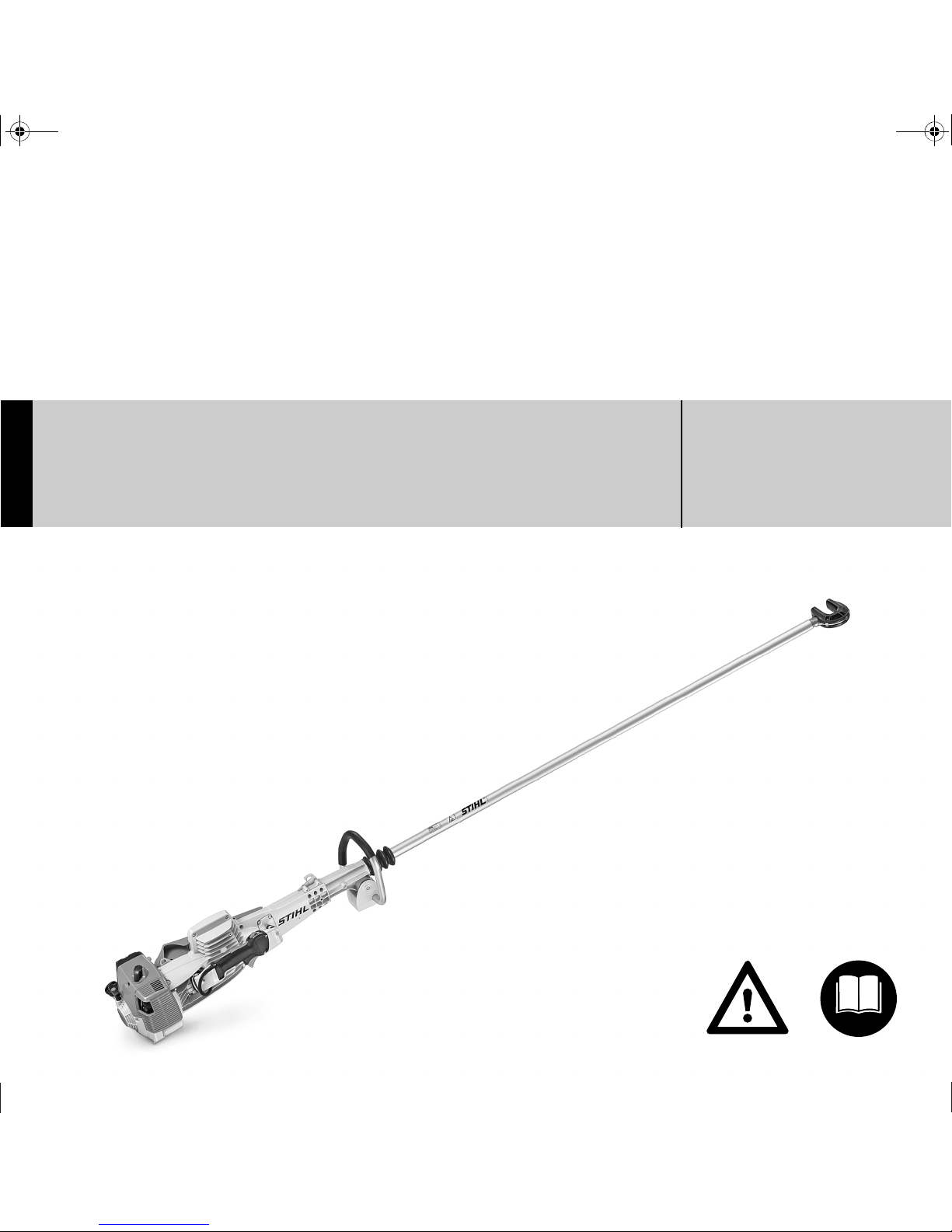
STIHL SP 451, 481 Instruction Manual
Page 2

Page 3

Original Instruction ManualPrinted on chlorine-free paper
Printing inks contain vegetable oils, paper can be recycled.
© ANDREAS STIHL AG & Co. KG, 2011
0458-418-0121-A. M0-125.A11.DDS.
0000001685_005_GB
SP 451, SP 481
English
1
{
Contents
Dear Customer,
Thank you for choosing a quality
engineered STIHL product.
This machine has been built using
modern production techniques and
comprehensive quality assurance.
Every effort has been made to ensure
your satisfaction and troublefree use
of the machine.
Please contact your dealer or our
sales company if you have any
queries concerning your machine.
Your
Hans Peter Stihl
Guide to Using this Manual 2
Safety Precautions and Working
Techniques 2
Using the Unit 6
Assembling the Unit 7
Adjusting the Throttle Cable 8
Fuel 8
Fueling 9
Starting / Stopping the Engine 10
Operating Instructions 13
Fitting the Harness 13
Transporting the Unit 15
Cleaning the Air Filter 16
Adjusting the Carburetor 16
Spark Plug 17
Engine Running Behavior 18
Replacing the Starter Rope and
Rewind Spring 19
Storing the Machine 20
Inspection and Maintenance by
User 21
Inspections and Maintenance by
Dealer 22
Maintenance and Care 23
Minimize Wear and Avoid Damage 25
Main Parts 26
Specifications 27
Special Accessories 28
Maintenance and Repairs 28
EC Declaration of Conformity 28
Quality Certification 29
Page 4

SP 451, SP 481
English
2
Pictograms
All the pictograms attached to the
machine are shown and explained in this
manual.
Symbols in text
Engineering improvements
STIHL's philosophy is to continually
improve all of its products. For this
reason we may modify the design,
engineering and appearance of our
products periodically.
Therefore, some changes, modifications
and improvements may not be covered
in this manual.
Observe all applicable local safety
regulations, standards and ordinances.
If you have not used this type of power
tool before: Have your dealer or other
experienced user show you how to
operate your power tool or attend a
special course in its operation.
Minors should never be allowed to use a
power tool.
Keep bystanders, especially children,
and animals away from the work area.
When the power tool is not in use, shut it
off so that it does not endanger others.
Secure it against unauthorized use.
The user is responsible for avoiding
injury to third parties or damage to their
property.
Do not lend or rent your power tool
without the instruction manual. Be sure
than anyone using your power tool
understands the information contained
in this manual.
The use of noise emitting power tools
may be restricted to certain times by
national or local regulations.
To operate the power tool you must be
rested, in good physical condition and
mental health.
If you have any condition that might be
aggravated by strenuous work, check
with your doctor before operating a
power tool.
Persons with pacemakers only: The
ignition system of your power tool
produces an electromagnetic field of a
very low intensity. This field may
interfere with some pacemakers. To
reduce health risks, STIHL recommends
that persons with pacemakers consult
their physician and the pacemaker
manufacturer before operating this tool.
Do not operate the power tool if you are
under the influence of any substance
(drugs, alcohol) which might impair
vision, dexterity or judgment.
Use the special harvester only for
shaking small trees, branches, bushes
and shrubs.
Do not use your harvester for any other
purpose since this may result in
accidents.
Only mount tools and accessories that
are explicity approved for this power tool
by STIHL or are technically identical. If
you have any questions in this respect,
consult a servicing dealer. Use only high
Guide to Using this Manual
Warning where there is a risk of
an accident or personal injury or
serious damage to property.
Caution where there is a risk of
damaging the machine or its
individual components.
Safety Precautions and
Working Techniques
Some special safety precautions must be
observed when working
with this harvester
because of the very high
oscillating speed of the
hook.
It is important you read
and understand the
instruction manual before
using your power tool for
the first time and keep
the manual in a safe
place for future reference. Non-observance of
the safety precautions
may result in serious or
even fatal injury.
Page 5
SP 451, SP 481
English
3
quality parts and accessories in order to
avoid the risk of accidents and damage
to the machine.
STIHL recommends the use of original
STIHL replacement parts. They are
specifically designed to match your
model and meet your performance
requirements.
Never attempt to modify your power tool
in any way since this may increase the
risk of personal injury. STIHL excludes
all liability for personal injury and
damage to property caused while using
unauthorized attachments.
Do not use a pressure washer to clean
the unit. The solid jet of water may
damage parts of the unit.
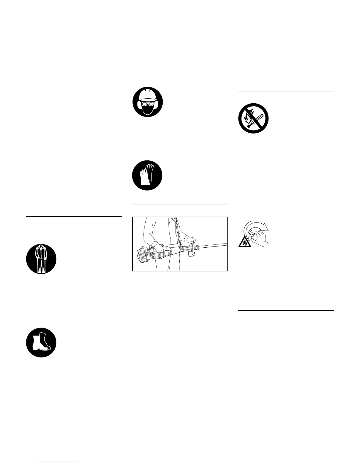
Clothing and Equipment
Wear proper protective clothing and
equipment.
Avoid clothing that could get caught on
branches or brush or moving parts of the
machine. Do not wear a scarf, necktie or
jewelry. Tie up and confine long hair
(e.g. with a hair net, cap, hard hat, etc.).
Warning! A face shield alone does not
provide adequate eye protection.
Wear hearing protection, e.g. earplugs
or ear muffs.
Transporting the Power Tool
Always stop the engine.
Carry the unit suspended from the
harness.
Transporting in a vehicle: Properly
secure your power tool to prevent
turnover, fuel spillage and damage.
Fueling
Always shut off the engine before
refueling.
Do not fuel a hot engine – fuel may spill
and cause a fire.
Open the fuel cap carefully to allow any
pressure build-up in the tank to release
slowly and avoid fuel spillage.
Fuel your power tool only in wellventilated areas. If you spill fuel, wipe
the machine immediately – if fuel gets on
your clothing, change immediately.
This reduces the risk of unit vibrations
causing the fuel cap to loosen or come
off and spill quantities of fuel.
Check for leakage. To reduce the risk of
serious of fatal burn injuries, do not
start or run the engine until leak is fixed.
Before starting
Check that your power tool is properly
assembled and in good condition – refer
to appropriate chapters in the instruction
manual.
Clothing must be sturdy
but allow complete freedom of movement. Wear
snug-fitting clothing, an
overall and jacket combination, do not wear a
work coat.
Wear steel-toed safety
boots with non-slip soles.
Wear a safety hard hat
where there is a danger
of head injuries from falling objects. Wear a face
shield and safety
glasses.
Wear heavy-duty gloves,
preferably made of
leather.
4902BA001 KN
Gasoline is an
extremely flammable
fuel. Keep clear of naked
flames. Do not spill any
fuel – do not smoke.
After fueling, tighten
down the screw-type fuel
cap as securely as
possible.
Page 6
SP 451, SP 481
English
4
– Slide control / stop switch must
move easily to STOP or 0.
– Smooth action of throttle trigger and
throttle trigger interlock – throttle
trigger must return automatically to
idle position.
– Check that the spark plug boot is
secure – a loose boot may cause
arcing that could ignite combustible
fumes and cause a fire.
– Keep the handles dry and clean –
free from oil and dirt – for safe
control of the power tool.
– Hook with rubber element: Properly
mounted and in good condition.
– Never attempt to modify the controls
or the safety devices in any way.
– Adjust the harness to suit your
height and reach – see "Fitting the
Harness".
To reduce the risk of personal injury,
do not operate your power tool if it is
damaged or not properly assembled.
For emergencies: Practise removing
and putting down the machine as you
would in an emergency. To avoid
damage, do not throw the machine to
the ground when practising – see also
"Fitting the Harness".
Starting the engine
Start the engine at least 3 meters from
the fueling spot, outdoors only.
Place the unit on firm ground in an open
area. Make sure you have good balance
and secure footing. Hold the unit
securely. The hook must be clear of the
ground and all other obstacles because
it may begin to run when the engine
starts.
Your harvester is a one-person unit. To
reduce the risk of injury from thrown
objects or contact with the shaft and
hook, do not allow other persons within
a radius of 10 meters of your own
position – even when starting.
Do not drop start the power tool – start
the engine as described in the
instruction manual.
Note that the hook continues to run for a
short period after you let go of the
throttle trigger (flywheel effect).
Make sure the idle speed setting is
correct. The hook must not move when
the engine is idling with the throttle
trigger released.
Check and correct the idle speed setting
at regular intervals. If the hook still
moves, have your dealer check your
machine and make proper adjustments
or repairs. STIHL recommends a STIHL
servicing dealer.
To reduce the risk of fire, keep hot
exhaust gases and hot muffler away
from easily combustible materials (e.g.
wood chips, bark, dry grass, fuel).
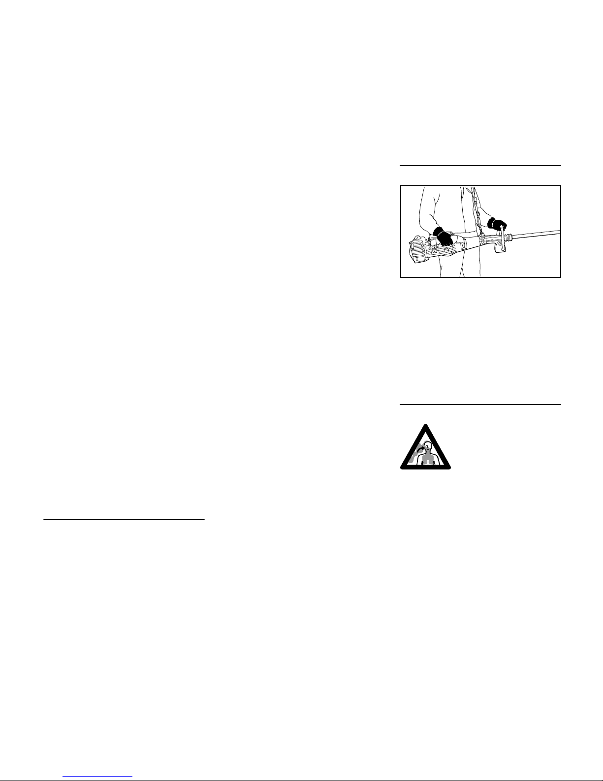
Holding and Controlling the Power
Tool
Always hold the unit on the right-hand
side of your body with both hands on the
handles.
Left hand on the front handle, right hand
on the control handle, even if you are
left-handed.
Make sure you always have good
balance and secure footing.
During Operation
To reduce the risk of serious or fatal
injury from breathing toxic fumes,
ensure proper ventilation when working
in trenches, hollows or other confined
locations.
Your power tool produces
toxic exhaust fumes as
soon as the engine is
running. These fumes
may be colorless and
odorless and contain
unburned hydrocarbons
and benzol. Never operate the power tool in
enclosed or poorly ventilated locations.
4902BA002 KN
Page 7

SP 451, SP 481
English
5
To reduce the risk of accidents, stop
work immediately in the event of
nausea, headache, visual disturbances
(e.g. reduced field of vision), problems
with hearing, dizziness, deterioration in
ability to concentrate. Apart from other
possibilities, these symptoms may be
caused by an excessively high
concentration of exhaust gases in the
work area.
The dusts, vapor and smoke produced
during operation may be dangerous to
health. If dust levels are very high, wear
a suitable respirator.
To reduce the risk of fire, do not smoke
while operating or standing near your
power tool. Note that combustible fuel
vapor may escape from the fuel system.
Operate your power tool so that it
produces a minimum of noise and
emissions – do not run the engine
unnecessarily, accelerate the engine
only for cutting.
Do not work alone – keep within calling
distance of others in case help is
needed.
Work calmly and carefully – in daylight
conditions and only when visibility is
good. Stay alert so as not to endanger
others.
Do not operate your power tool in the
starting throttle position. Engine speed
cannot be controlled with the throttle
trigger in this position.
Opening the throttle while the hook is
blocked increases the load and reduces
engine speed. The clutch then slips
continuously and this causes
overheating and damage to important
components (e.g. clutch, polymer
housing components) – and this can
increase the risk of injury from the hook
moving while the engine is idling.
To reduce the risk of personal injury
from falling branches, fruit, etc., do not
allow any other persons within a radius
of 15 meters of your own position while
you are working.
Special care must be taken when
working in difficult, over-grown terrain.
Take special care in slippery conditions
– damp, slopes, fruit on the ground and
on uneven ground.
Watch out for obstacles: Watch out for
tree stumps, roots and fallen fruit to
avoid stumbling.
Be particularly alert and cautious when
wearing hearing protection because
your ability to hear warnings (shouts,
alarms, etc.) is restricted.
Before starting work, check the safety
devices for damage or wear. Always
replace damaged parts. Never operate
your power tool with damaged safety
devices.
Check the hook, rubber element and
shaft at regular short intervals or
immediately if there is a noticeable
change in the tool's behavior:
– Shut off the engine and hold the unit
firmly.
– Check condition – look for cracks.
– Replace damaged parts
immediately, even if they have only
superficial cracks.
To reduce the risk of unintentional
engine start and injury, always shut off
the engine before replacing the hook
and shaft.
Do not continue using or attempt to
repair a damaged or cracked hook by
welding or straightening.
After finishing work or before leaving the
unit unattended: Shut off the engine.
Vibrations
Recommendation: Several persons
should share the day's work with the
harvester by rotating at regular intervals.
No general recommendation can be
given for the length of usage because it
depends on several factors.
The period of usage is prolonged by:
– Hand protection (wearing warm
gloves)
– Work breaks
The period of usage is shortened by:
– Any personal tendency to suffer
from poor circulation (symptoms:
frequently cold fingers, tingling
sensations).
– Low outside temperatures.
– The force with which the handles
are held (a tight grip restricts
circulation).
Seek medical advice immediately if any
of the following symptoms appear:
The function of this harvester causes vibrations.
Some of these vibrations
are transmitted to the
handles. Therefore, the
permissible period of
daily usage for one operator is restricted.
Page 8

SP 451, SP 481
English
6
– Fingers turning white – especially in
cold weather.
– Tingling sensations and numbness
in fingers (after using the machine).
– Constant pains in muscles or joints.
– Difficulty gripping or holding small
objects, such as screws, nails, etc.
Operators with the above symptoms
should not use the machine until further
notice.
An aid to calculating the daily exposure
to vibrations can be found on
www.stihl.com/vib. Dealers can also
provide information on daily exposure to
vibrations. STIHL recommends you
consult a STIHL servicing dealer in this
respect.
Maintenance and Repairs
Service the machine regularly. Do not
attempt any maintenance or repair work
not described in the instruction manual.
Have all other work performed by a
servicing dealer.
STIHL recommends that you have
servicing and repair work carried out
exclusively by an authorized STIHL
servicing dealer. STIHL dealers are
regularly given the opportunity to attend
training courses and are supplied with
the necessary technical information.
Only use high-quality replacement parts
in order to avoid the risk of accidents
and damage to the machine. If you have
any questions in this respect, consult a
servicing dealer.
STIHL recommends the use of genuine
STIHL replacement parts. They are
specifically designed to match your
model and meet your performance
requirements.
To reduce the risk of injury, always shut
off the engine before carrying out any
maintenance or repairs or cleaning the
machine. – Exception: Carburetor and
idle speed adjustments.
Do not turn the engine over on the
starter with the spark plug boot or spark
plug removed unless the slide control /
stop switch is on STOP or 0 since there
is otherwise a risk of fire from
uncontained sparking.
To reduce the risk of fire, do not service
or store your machine near open flames.
Check the fuel filler cap for leaks at
regular intervals.
Use only a spark plug of the type
approved by STIHL and make sure it is
in good condition – see "Specifications".
Inspect the ignition lead (insulation in
good condition, secure connection).
Check the condition of the muffler.
To reduce the risk of fire and damage
to hearing, do not operate your
machine if the muffler is damaged or
missing.
Do not touch a hot muffler since burn
injury will result.
Vibration behavior is influenced by the
condition of the AV elements – check the
AV elements at regular intervals.
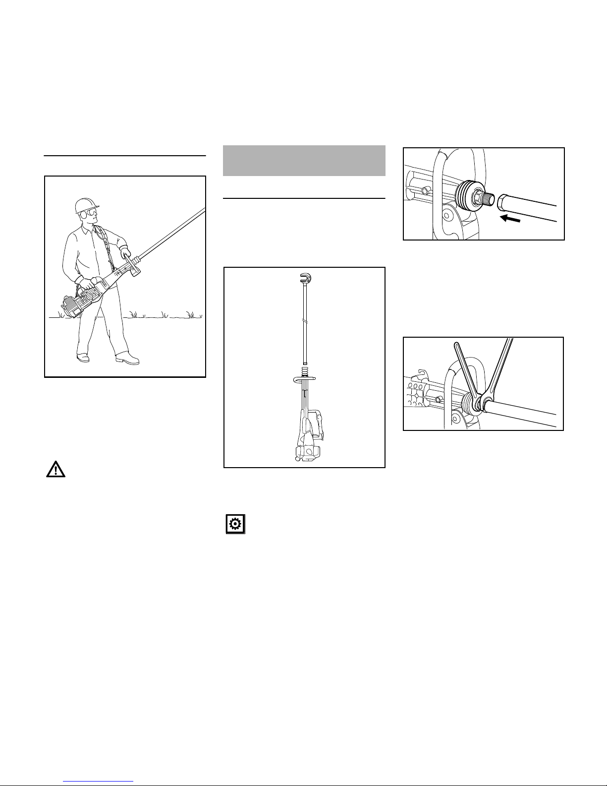
Preparations
N Start the engine – see
"Starting / Stopping the Engine".
N Put on the harness – see "Fitting the
Harness".
N Attach the hook (1) to a branch –
rotate the shaft (2) to turn the hook
to the required position.
Using the Unit
Do not operate the harvester
without the harness.
2
1
4902BA003 KN
Page 9
SP 451, SP 481
English
7
Working Position
N With the harvester suspended from
the harness (3), hold the control
handle with your right hand and hold
and control the unit with your left
hand on the front handle (4).
N Open the throttle and begin work
Mounting the Shaft
N Place the powerhead on a clean
and flat surface so that it is resting
on the guard plate and the machine
support (under the front handle).
N Place the shaft (1) in front of the
powerhead and check that both
parts form a straight line.
N Push back the hand guard (2) to
expose the thread (3) on the
pushrod.
N Hold the hand guard in this position
and screw the shaft (1) onto the
pushrod's thread by hand – as far as
stop.
N Position the 27mm open-end
wrench on the pushrod's hexagon.
N Position the 34mm open-end
wrench on the shaft's hexagon.
Do not grip the shaft during
operation because its movements
will otherwise be transmitted
directly to your body – the
anitivibration system will be
bypassed – see also section on
"Vibrations" in "Safety Precautions
and Working Techniques".
3
4902BA004 KN
4
Assembling the Unit
Make sure the ends of the shaft
and pushrod are clean.
4902BA005 KN
1
1
3
2
4902BA006 KN
4902BA007 KN
SW 27
SW 34
Page 10
SP 451, SP 481
English
8
N Hold the pushrod steady with the
27mm wrench and tighten down the
shaft firmly.
Removing the Shaft
The shaft can be removed again to save
space when transporting the machine.
See chapter on "Transporting the
Machine".
Attaching the Harness
N Attach the harness to the machine
and put it on – see "Putting on the
Harness".
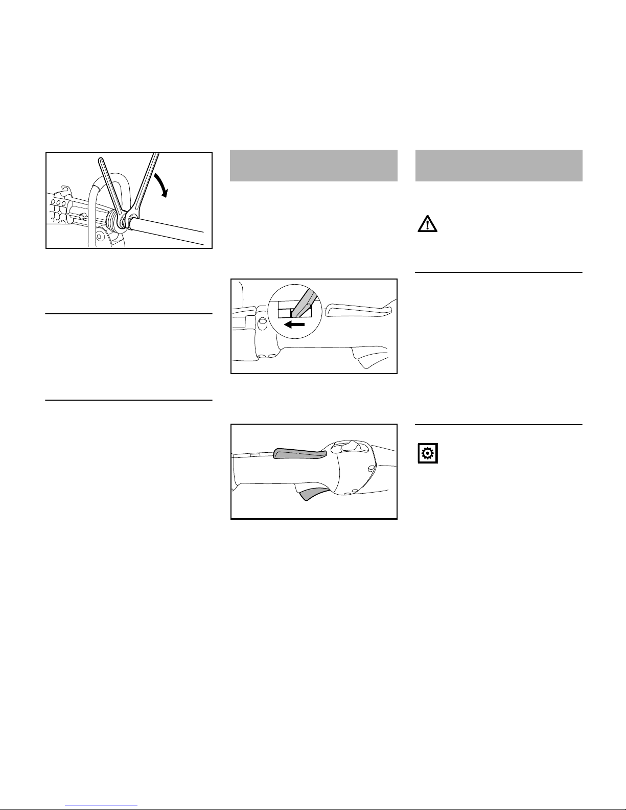
A properly adjusted throttle cable is the
precondition for correct operation in the
starting throttle, idle and full throttle
positions.
N Adjust the throttle cable only when
the unit is completely and properly
assembled.
N Use a suitable tool to push the slide
to the end of the slot (see
illustration).
N Press down the throttle trigger
lockout (1) and squeeze the throttle
trigger (2) (full throttle) – this sets
the throttle cable correctly.
Your engine requires a mixture of
gasoline and engine oil.
STIHL MotoMix
STIHL recommends the use of STIHL
MotoMix. This ready-to-use fuel mix
contains no benzol or lead, has a high
octane rating and ensures that you
always use the right mix ratio.
STIHL MotoMix is specially formulated
for use in STIHL engines and
guarantees a long engine life.
MotoMix is not available in all markets.
Mixing Fuel
Gasoline
Use only high-quality brand-name
gasoline with a minimum octane rating
of 90 – leaded or unleaded.
If your machine is equipped with a
catalytic converter, you must use
unleaded gasoline.
4902BA008 KN
SW 27
SW 34
Adjusting the Throttle
Cable
4902BA009 KN
1
2
4902BA010 KN
Fuel
For health reasons, avoid direct
skin contact with gasoline and
avoid inhaling gasoline vapor.
Unsuitable fuels or lubricants or
mix ratios other than those
specified may result in serious
damage to the engine. Poor
quality gasoline or engine oil may
damage the engine, sealing rings,
hoses and the fuel tank.
Page 11

SP 451, SP 481
English
9
Engine Oil
Use only quality two-stroke engine oil.
We recommend STIHL two-stroke
engine oil since it is specially
formulated for use in STIHL engines
and guarantees a long engine life.
If STIHL two-stroke engine oil is not
available, use only quality two-stroke oil
designed for use in air-cooled engines.
Do not use oils designed for watercooled engines or engines with a
separate lubricating system (e.g.
conventional four-stroke engines).
Use only STIHL 50:1 two-stroke
engine oil for the fuel mix in models with
a catalytic converter.
Mix Ratio
STIHL 50:1 two-stroke engine oil: 50
parts gasoline to 1 part oil
Examples
N Use a canister approved for storing
fuel. Pour oil into canister first, then
add gasoline and mix thoroughly.
Storing Fuel
Store fuel only in approved safety-type
fuel canisters in a dry, cool and safe
location protected from light and the sun.
Fuel mix ages – only mix sufficient fuel
for a few weeks work. Do not store fuel
mix for longer than 3 months. Exposure
to light, the sun, low or high
temperatures can quickly make the fuel
mix unusable.
N Thoroughly shake the mixture in the
canister before fueling your
machine.
N Clean the fuel tank and canister
from time to time.
Dispose of remaining fuel and cleaning
fluid properly in accordance with local
regulations and environmental
requirements.
Preparations
N Before fueling, clean the filler cap
and the area around it to ensure that
no dirt falls into the tank.
N Position the machine so that the
filler cap is facing up.
Filling up with fuel
Take care not to spill fuel while fueling
and do not overfill the tank. STIHL
recommends you use the STIHL filler
nozzle for fuel (special accessory).
A few tankfuls of leaded gasoline
will greatly reduce the efficiency of
the catalytic converter.
Gasoline STIHL engine oil 50:1
Liters Liters (ml)
10,02(20)
5 0,10 (100)
10 0,20 (200)
15 0,30 (300)
20 0,40 (400)
25 0,50 (500)
Other brand-name two-stroke
engine oils: 25 parts gasoline to 1
part oil
Pressure may build up in the
canister – open it carefully.
Fueling
256BA060 KN
Page 12

SP 451, SP 481
English
10
N Open the filler cap.
N Filling up with fuel
N Close the filler cap.
Changing the Fuel Pickup Body
Change the fuel pickup body every year:
N Open the filler cap and drain the fuel
tank.
N Use a hook to pull the fuel pickup
body out of the tank and take it off
the hose.
N Push the new pickup body into the
hose.
N Place the pickup body in the tank.
N Fill up with fuel and close the filler
cap.
Control Handle
Controls
1 Throttle trigger lockout
2 Throttle trigger
3 Slide control
Positions of slide control
4STOP-0 – engine off – the ignition is
switched off
5 F – normal run position – the engine
is running or can start
6 START – the ignition is switched on
– the engine can start
After fueling, tighten down the
filler cap as securely as possible
by hand.
Do not kink the fuel hose – do not
use any sharp or pointed tools.
412BA060 KN
Starting / Stopping the
Engine
START
STOP-
3
STOP
2
5
6
4
7
4902BA011 KN
1
Page 13

SP 451, SP 481
English
11
Symbol on slide control
7 h – stop symbol and arrow. To stop
the engine, push the slide control in
the direction of the arrow on the stop
symbol (h) to STOP-0.
Starting
N Press down the trigger lockout lever
and squeeze the throttle trigger.
N Hold both levers in this position.
N Move the slide control to START
and hold it there.
N Now release the throttle trigger,
slide control and trigger lockout in
that order. This is the starting
throttle position.
N Set the choke knob (8):
N Press the fuel pump bulb (9) at least
five times – even if the bulb is
already filled with fuel.
N Press in the decompression valve
button (10) before each starting
attempt.
Cranking
N Place the unit on the ground: It must
rest on the guard plate on the
underside of the powerhead and the
machine support under the front
handle. Check that the hook is not
touching the ground of any other
obstacles.
N Make sure you have a firm footing.
N Hold the unit with your left hand and
press it down firmly.
N Pull the starter grip slowly with your
right hand until you feel it engage
and then give it a brisk strong pull.
N Do not let the starter grip snap back.
Guide it slowly back into the housing
so that the starter rope can rewind
properly.
N Continue cranking until engine fires.
When the engine begins to fire:
N Turn the choke knob to e.
N Press in button to open the
decompression valve.
N Continue cranking until the engine
runs.
g If the engine is cold
e for warm start – also use this posi-
tion if the engine has been running
but is still cold.
250BA018 KN
9
8
10
4902BA012 KN
4902BA013 KN
4902BA014 KN
Do not pull out the starter rope all
the way – it might otherwise
break.
4902BA015 KN
Page 14

SP 451, SP 481
English
12
As soon as the engine runs
N Blip the throttle trigger
immediately. The slide control
moves to the normal run position F
– and the engine settles down to idle
speed.
Your machine is now ready for
operation.
Stopping the Engine
N Push the slide control in the
direction of the arrow on the stop
symbol (h) to STOP-0.
At very low outside temperatures:
As soon as the engine runs:
N Blip the throttle trigger to disengage
the starting throttle position. The
slide control moves to the normal
run position (F) – and the engine
settles down to idle speed.
N Open the throttle slightly.
N Warm up the engine briefly.
If the engine does not start
Choke knob
If you did not turn the choke knob to e
quickly enough after the engine began to
fire, the combustion chamber is flooded.
N Turn the choke knob to e.
N Select the starting throttle
position.
N Start the engine by pulling the
starter rope briskly – 10 to 20 pulls
may be necessary.
If the engine still does not start
N Move the slide control to STOP-0.
N Remove the spark plug – see
"Spark Plug".
N Dry the spark plug.
N Open the throttle wide and hold it
that position.
N Crank the engine several times with
the starter to clear the combustion
chamber.
N Refit the spark plug – see "Spark
Plug".
N Connect the spark plug boot (press
it down firmly).
N Move the slide control to START.
N Set the choke knob to e – even if
the engine is cold.
N Start the engine.
Throttle cable adjustment
N Check adjustment of throttle cable –
see chapter on "Adjusting the
Throttle Cable".
Fuel tank run until completely dry
N After refueling, press the fuel pump
bulb at least five times – even if the
bulb is filled with fuel.
N Set the choke knob according to
engine temperature.
N Now start the engine.
Make sure the carburetor is
correctly adjusted. The hook must
not move when the engine is
idling.
Page 15

SP 451, SP 481
English
13
During break-in period
A factory-new machine should not be
run at high revs (full throttle off load) for
the first three tank fillings. This avoids
unnecessary high loads during the
break-in period. As all moving parts
have to bed in during the break-in
period, the frictional resistances in the
engine are greater during this period.
The engine develops its maximum
power after about 5 to 15 tank fillings.
During Operation
After a long period of full throttle
operation, allow the engine to run for a
short while at idle speed so that engine
heat can be dissipated by the flow of
cooling air. This protects enginemounted components (ignition,
carburetor) from thermal overload.
After Finishing Work
Storing for a short period: Wait for the
engine to cool down. Empty the fuel tank
and keep the machine in a dry place,
well away from sources of ignition, until
you need it again. For longer out-ofservice perionds – see "Storing the
Machine".
Using a harness
STIHL recommends you use the
harness supplied with the machine
because it is specifically designed to
match the machine and the application,
and ensure ergonomic operation.
Putting on the harness and attaching
it to the machine
N Put your left arm through the
opening in the harness (1).
N Place the harness (1) on your left
shoulder.
– The carabiner (2) is on the left side
of your body.
– The carrying loop (3) is on the left
side of your body.
N Squat down on the left-hand side of
the machine to save your back
when lifting the machine.
N Attach the carabiner (2) to the rear
carrying ring (4).
N Engage the loop (3) in the front hook
(5) by pulling the loop firmly over the
locking bar (6).
Operating Instructions Fitting the Harness
4902BA016 KN
2
3
4902BA017 KN
4
b
4902BA018 KN
c
a
2
6
5
4902BA019 KN
3
Page 16

SP 451, SP 481
English
14
N Straighten out the harness and
straps.
N Stand upright from the squatting
position and lift the machine at the
same time – it hangs at the right
side of your body.
Adjusting the harness straps
Adjust the length of the straps with the
sliding adjusters (arrows).
Tightening the harness straps
N Pull the end of the strap down to
tighten the strap.
Loosening the harness straps
N Press the sliding adjuster down to
loosen the strap.
N Adjust the length of the straps so
that the machine is at an angle with
the hook pointing slightly up.
Putting the machine down and
disengaging the harness
N Squat down and put the machine on
the ground.
N Slip the harness off your left
shoulder and your arm.
4902BA020 KN
4902BA021 KN
4902BA022 KN
4902BA023 KN
4902BA024 KN
Page 17

SP 451, SP 481
English
15
N Disconnect the carabiner (2) from
the rear carrying ring (4).
N Pull the loop (3) out of the front hook
by pulling it firmly over the locking
bar (6).
Throwing off the machine in an
emergency
N Quickly pull the loop out of the front
hook.
N Slip the harness off your left
shoulder and your arm.
N Let the machine and harness fall to
the ground.
The shaft with hook can be removed to
save space when transporting the
machine.
Removing the Harness
N If necessary, disconnect the
harness from the machine – see
"Fitting the Harness".
Removing the Shaft
N Put the machine down on a clean
and level surface so that it rests on
the guard plate and the machine
support (under the front handle).
Make sure the hook is not touching
the ground or any other obstacles.
N Push back the hand guard (1) to
expose the hexagon ends of the
shaft (2) and pushrod (3).
N First position the 27mm open-end
wrench on the pushrod's hexagon.
N Position the 34mm open-end
wrench on the shaft's hexagon.
N Loosen and unscrew the shaft from
the pushrod's thread.
Mounting the Shaft
N Refit the shaft – see "Assembling
the Unit".
Attaching the Harness
N Attach the harness to the machine
and put it on – see "Fitting the
Harness".
The machine and harness must
be quickly thrown off in an
emergency. To do this:
4
c
4902BA025 KN
a
b
2
3
4902BA026 KN
6
5
Transporting the Unit
3
2
1
4902BA027 KN
Make sure the ends of the shaft
and pushrod are clean.
4902BA028 KN
SW 27
SW 34
Page 18

SP 451, SP 481
English
16
Dirty air filters reduce engine power,
increase fuel consumption and make
starting more difficult.
If there is a noticeable loss of engine
power
N Turn the choke knob to g
N Loosen the screw (1).
N Remove the filter cover (2).
N Clean away loose dirt from around
the filter and inside the filter cover.
N Remove and check the filter
element (3) – replace if dirty or
damaged.
N Install the filter element in the filter
cover.
N Fit the filter cover.
The carburetor comes from the factory
with a standard setting.
This setting provides an optimum fuel-air
mixture under most operating
conditions.
With this carburetor it is only possible to
adjust the high speed and low speed
screws within fine limits.
Standard Setting
N Stopping the Engine
N Check the air filter and replace it if
necessary.
N Check that the throttle cable is
properly adjusted – readjust if
necessary – see chapter on
"Adjusting the Throttle Cable".
N Turn the high speed screw (H)
counterclockwise as far as stop (no
more than 3/4 turn).
N Turn the low speed screw (L)
carefully clockwise as far as stop,
then turn it back 1 full turn.
N Start and warm up the engine if
necessary.
N Adjust idle speed with the idle speed
screw (LA) so that the hook does
not move.
Fine Tuning
A slight correction of the setting of the
high speed screw (H) may be necessary
if engine power is not satisfactory when
operating at high altitude or at sea level.
Cleaning the Air Filter
1
2
3
256BA062 KN
Adjusting the Carburetor
Adjustments may be performed
only when the machine is
completely and securely
assembled.
412BA076 KN
Page 19

SP 451, SP 481
English
17
N Turn the high speed screw (H)
about one eighth of a turn for every
1000m change in altitude.
N Carry out standard setting on low
speed screw (L).
N Warm up the engine for about 3
minutes.
N Open the throttle wide.
At high altitude
N Turn the high speed screw (H)
clockwise (leaner), no further than
stop, until there is no further
noticeable increase in engine
speed.
At sea level
N Turn the high speed screw (H)
counterclockwise (richer), no further
than stop, until there is no further
noticeable increase in engine
speed.
It is possible that maximum engine
speed may be reached with the standard
setting in each case.
Adjusting Idle Speed
It is usually necessary to change the
setting of the idle speed screw (LA) after
every correction to the low speed
screw (L).
N Warm up the engine for about 3
minutes.
Engine stops while idling
N Turn the idle speed screw (LA)
slowly clockwise until the engine
runs smoothly – the hook must not
move.
Hook runs when engine is idling
N Turn the idle speed screw (LA)
counterclockwise until the hook
stops moving and then rotate the
screw another 1/2 to 1 turn in the
same direction.
Erratic idling behavior, engine stops
even though setting of LA-screw has
been corrected, poor acceleration
Idle setting is too lean
N Turn the low speed screw (L)
counterclockwise, no further than
stop, until the engine runs and
accelerates smoothly.
Erratic idling behavior
Idle setting is too rich
N Turn the low speed screw (L)
clockwise, no further than stop, until
the engine runs and accelerates
smoothly.
N If the engine is down on power,
difficult to start or runs poorly at idle
speed, first check the spark plug.
N Fit a new spark plug after about 100
operating hours – or sooner if the
electrodes are badly eroded. Install
only suppressed spark plugs of the
type approved by STIHL – see
"Specifications".
Removing the spark plug
N Move the slide control to STOP-0
(h).
N Pull off the spark plug boot (1).
N Unscrew the spark plug.
If the hook continues moving
when the engine is idling, have
your power tool checked and
repaired by your servicing dealer.
Spark Plug
271BA073 KN
Page 20

SP 451, SP 481
English
18
Checking the spark plug
N Clean dirty spark plug.
N Check electrode gap (A) and
readjust if necessary – see
"Specifications".
N Rectify the problems which have
caused fouling of the spark plug.
Possible causes are:
– Too much oil in fuel mix.
– Dirty air filter.
– Unfavorable running conditions.
Installing the spark plug
N Screw the spark plug (3) into the
cylinder and fit the boot (2) (press it
down firmly).
If engine running behavior is
unsatisfactory even though the air filter
is clean and the carburetor and throttle
cable are properly adjusted, the cause
may be the muffler.
Have the muffler checked by a servicing
dealer for contamination
(carbonization).
STIHL recommends that you have
servicing and repair work carried out
exclusively by an authorized STIHL
servicing dealer.
If the spark plug comes with a
detachable adapter nut (1), screw
the adapter onto the thread and
tighten it down firmly to reduce
the risk of arcing and fire.
000BA039 KN
A
1
000BA045 KN
3
002BA178 KN
2
Engine Running Behavior
Page 21

SP 451, SP 481
English
19
Removing the Fan Housing
N Take out the screws (1).
N Remove the fan housing.
Replacing the Starter Rope
N Remove the spring clip (2).
N Carefully remove the rope rotor with
washer (3) and pawl (4).
N Pry the cap (5) out of the grip.
N Remove the remaining rope from
the rotor and starter grip.
N Tie a simple overhand knot in the
new rope and then thread it through
the top of the grip and the rope
bushing (6).
N Refit the cap in the grip.
N Pull the rope through the rotor and
secure it with a simple overhand
knot.
N Coat rope rotor bearing bore with
non-resinous oil – see "Special
Accessories".
N Slip the rotor over the starter post –
turn it back and forth to engage the
anchor loop of the rewind spring.
N Fit the pawl (4).
N Fit the washer (3).
N Push the spring clip (2) into position
– it must point counterclockwise as
shown and engage the pawl's peg.
Replacing the Starter Rope
and Rewind Spring
The rewind spring may pop out
and uncoil during this operation –
take care to avoid the risk of
injury.
1
1
1
1
256BA075 KN
3
2
4
256BA032 KN
6
5
256BA033 KN
256BA034 KN
3
2
4
256BA032 KN
Page 22

SP 451, SP 481
English
20
Tensioning the Rewind Spring
N Make a loop in the unwound starter
rope and use it to turn the rope rotor
six full revolutions
counterclockwise.
N Hold the rotor steady.
N Pull out and straighten the twisted
rope.
N Let go of the rotor.
N Release the rope slowly so that it
winds onto the rotor.
The starter grip must sit firmly in the rope
bushing. If the grip droops to one side:
Add one more turn on the rope rotor to
increase spring tension.
N Take one turn of the rope off the
rotor.
N Fit the fan housing.
Replacing a Broken Rewind Spring
N Remove the rope rotor as described
in "Replacing the Starter Rope".
N Take out the screws (7).
N Remove the spring housing and
pieces of spring.
N Lubricate the new, ready-to-fit
replacement spring in the new
spring housing with a few drops of
resin-free oil – see "Special
Accessories".
N Place the replacement spring with
spring housing in position – bottom
plate facing up.
If the spring pops out of the housing
during installation: Refit it clockwise,
starting outside and working inwards.
N Fit the screws.
N Refit the rope rotor as described in
"Replacing the Starter Rope".
N Tension the rewind spring.
N Fit the fan housing.
For periods of 3 months or longer
N Drain and clean the fuel tank in a
well ventilated area.
N Dispose of fuel properly in
accordance with local
environmental requirements.
N Run the engine until the carburetor
is dry – this helps prevent the
carburetor diaphragms sticking
together.
N Thoroughly clean the machine –
pay special attention to the cylinder
fins and air filter.
N Store the machine in a dry, high or
locked location, – out of the reach of
children and other unauthorized
persons.
When the starter rope is fully
extended it must still be possible
to rotate the rotor another one and
a half turns. If this is not the case,
the spring is overtensioned and
could break.
427BA016 KN
The bits of the spring may still be
under tension and could fly apart
when you remove the rope rotor
and spring housing. To reduce
the risk of injury, wear face
protection and work gloves.
7
7
271BA053 KN
Storing the Machine
Page 23

SP 451, SP 481
English
21
Visual Inspection
N Visually inspect the whole machine
before each use and after every
refueling stop.
Screws and Nuts
N Check all accessible screws and
nuts (not the carburetor adjusting
screws) about every 25 hours of
operation.
N Check the screw union of the shaft
and pushrod in the hand guard after
every refueling stop – see
"Assembling the Unit".
Replacing the Rubber Element on the
Hook
Removing the rubber element
N Use a suitable tool to pry the clips
(1) out of the hook (2).
N Do not re-use damaged or bent
clips. Always fit new ones.
N Cut the worn rubber element (3) so
that it can be easily pulled off the
hook.
Installing the rubber element
N Coat the new rubber element (3)
and the hook (2) thoroughly with
STIHL press fluid OH 723 – see
"Special Accessories".
N Push the hook into the rubber
element as shown.
N Insert the clips (1) in the rubber
element and press them home as
far as stop.
Inspection and
Maintenance by User
4902BA034 KN
4902BA035 KN
4902BA036 KN
4902BA037 KN
4902BA038 KN
4902BA039 KN
Page 24

SP 451, SP 481
English
22
Correct position of clips
Lubricating the Pushrod
N Check the grease level regularly –
about every 150 hours of operation.
N Unscrew the filler plug (1). If no
grease can be seen on the inside of
the filler plug, screw the tube (2) of
STIHL gear lubricant for
brushcutters (special accessory)
into the filler hole.
N Squeeze grease into the housing.
N Remove the tube of grease (2).
N Refit the filler plug and tighten it
down firmly.
Maintenance Work
STIHL recommends that you have
servicing and repair work carried out
exclusively by an authorized STIHL
servicing dealer.
Antivibration System (AV system)
Rubber elements are installed in the
machine to reduce vibrations.
There are two rubber elements (1) in
front of and behind the control handle
(2). A further rubber element (3) is
installed in the machine support (4).
N Have the rubber elements checked
at least after every 50 hours of
operation, or if there any visible
signs of wear and/or if there is a
noticeable increase in vibrations.
Do not completely fill the housing
with grease.
4902BA040 KN
1
4902BA041 KN
2
Inspections and
Maintenance by Dealer
4902BA042 KN
1
2
3
4
Page 25

SP 451, SP 481
English
23
Maintenance and Care
The following intervals apply to normal operating conditions only. If your daily working time is longer or operating conditions are difficult (very dusty work area, etc.),
shorten the specified intervals accordingly.
before starting work
after finishing work or daily
after each refueling stop
weekly
monthly
every 12 months
if problem
if damaged
if required
Complete machine
Visual inspection (condition, leaks) XX
Clean X
Control handle Check operation XX
Air filter
Clean XX
Replace X
Pickup body in fuel tank
Check X
Replace XXX
Fuel tank Clean XXX
Carburetor
Check idle adjustment – the hook must
not move
XX
Adjusting Idle Speed X
Spark plug
Adjust electrode gap X
Replace after every 100 operating hours
Cooling inlets
Visual Inspection X
Clean X
Spark arresting screen
1)
in muffler
Check
2)
XX
Clean or replace
2)
X
All accessible screws and nuts (not adjusting screws)
Retighten X
Antivibration elements
Check XXX
Replace
2)
XX
Hook with rubber element
Visual Inspection XX
Check tightness XX
Replace XX
Page 26

SP 451, SP 481
English
24
All accessible screws and nuts (not adjusting screws)
Retighten X
Pushrod lubrication
Check XXX
Replenish X
Safety labels Replace X
1)
not in all versions, market-specific
2)
STIHL recommends that this work be done by a STIHL servicing dealer
The following intervals apply to normal operating conditions only. If your daily working time is longer or operating conditions are difficult (very dusty work area, etc.),
shorten the specified intervals accordingly.
before starting work
after finishing work or daily
after each refueling stop
weekly
monthly
every 12 months
if problem
if damaged
if required
Page 27

SP 451, SP 481
English
25
Observing the instructions in this manual
helps reduce the risk of unnecessary
wear and damage to the power tool.
The power tool must be operated,
maintained and stored with the due care
and attention described in this owner's
manual.
The user is responsible for all damage
caused by non-observance of the safety
precautions, operating and maintenance
instructions in this manual. This includes
in particular:
– Alterations or modifications to the
product not approved by STIHL.
– Using tools or accessories which
are neither approved or suitable for
the product or are of a poor quality.
– Using the product for purposes for
which it was not designed.
– Using the product for sports or
competitive events.
– Consequential damage caused by
continuing to use the product with
defective components.
Maintenance Work
All the operations described in the
"Maintenance Chart" must be performed
on a regular basis. If these maintenance
operations cannot be performed by the
owner, they should be performed by a
servicing dealer.
STIHL recommends that you have
servicing and repair work carried out
exclusively by an authorized STIHL
servicing dealer. STIHL dealers are
regularly given the opportunity to attend
training courses and are supplied with
the necessary technical information.
If these maintenance operations are not
carried out as specified, the user
assumes responsibility for any damage
that may occur. Among other parts, this
includes:
– Damage to the engine due to
neglect or deficient maintenance
(e.g. air and fuel filters), incorrect
carburetor adjustment or
inadequate cleaning of cooling air
inlets (intake ports, cylinder fins).
– Corrosion and other consequential
damage resulting from improper
storage.
– Damage to the machine resulting
from the use of poor quality
replacement parts.
Parts Subject to Wear and Tear
Some parts of the power tool are subject
to normal wear and tear even during
regular operation in accordance with
instructions and, depending on the type
and duration of use, have to be replaced
in good time. Among other parts, this
includes:
– Rubber element on hook
– Shaft with hook
– Gearbox
– Clutch
– Filters (air, fuel)
– Rewind starter
– Spark plug
– Components of antivibration system
Minimize Wear and Avoid
Damage
Page 28

SP 451, SP 481
English
26
1 Hook
2 Shaft
3 Hand guard
4 Handle
5 Machine support
6 Hook
7 Carrying ring
8 Fuel pump
9 Choke knob
10 Filter cover
11 Fuel tank
12 Guard plate
13 Throttle cable
14 Control handle
15 Throttle trigger lockout
16 Slide control
17 Throttle trigger
18 Filler plug
19 Pushrod
20 Fuel filler cap
21 Carburetor adjusting screws
22 Starter grip
23 Decompression valve
24 Spark plug boot
25 Muffler (with spark arrestor in some
markets)
26 Harness
# Serial number
Main Parts
13
19
15
14
7 8
4902BA043 KN
1
#
2
6
4
11
10
9
16
18
5
3
12
17
24
23
25
20
21
22
26
Page 29

SP 451, SP 481
English
27
Engine
STIHL single cylinder two-stroke engine
SP 451
SP 481
Ignition System
Electronic magneto ignition
Fuel System
All position diaphragm carburetor with
integral fuel pump
Weight
Hook
Length
Noise and Vibration Data
Noise measurements include idling and
rated maximum speed, vibration
measurements idling and full load with
the same duration of exposure in each
case.
For further details on compliance with
Vibration Directive 2002/44/EC see
www.stihl.com/vib/
Tool: Hook
Sound pressure level L
peq
to
ISO 11201
Sound power level L
weq
to ISO 3744
Vibration measurement a
hv,eq
to
ISO 20643
The K-factor in accordance with
Directive 2006/42/EC is 2.5 dB(A) for
the sound pressure level and sound
power level; the K-factor in accordance
with Directive 2006/42/EC is 2.0 m/s
2
for the vibration measurement.
REACH
REACH is an EC regulation and stands
for the Registration, Evaluation,
Authorisation and Restriction of
Chemical substances.
For information on compliance with the
REACH regulation (EC) No. 1907/2006
see www.stihl.com/reach.
Specifications
Displacement: 44.3 cm
3
Bore: 42 mm
Stroke: 32 mm
Engine power to
ISO 8893:
2.1 kW (2.9 HP)
at 9,000 rpm
Cut-off speed
(rated): 12,500 rpm
Idle speed: 2,800 rpm
Displacement: 48.7 cm
3
Bore: 44 mm
Stroke: 32 mm
Engine power to
ISO 8893:
2.2 kW (3.0 HP)
at 9,000 rpm
Cut-off speed
(rated): 12,500 rpm
Idle speed: 2,800 rpm
Spark plug (resistor
type):
Bosch WSR 6 F,
NGK BPMR 7 A
Electrode gap: 0.5 mm
Fuel tank capacity: 0.67 l
Overall weight, dry, with
harness: 13.9 kg
Powerhead, dry: 12.8 kg
Shaft with hook: 1.1 kg
Opening: 42 mm
Stroke: 45 mm
Strokes per minute at
12,500 rpm: 3328
Overall length: 2865 mm
Shaft with hook: 1860 mm
SP 451: 102 dB(A)
SP 481: 102 dB(A)
SP 451: 113 dB(A)
SP 481: 113 dB(A)
Handle, left
Handle,
right
SP 451: 5.7 m/s
2
5.7 m/s
2
SP 481: 5.7 m/s
2
5.7 m/s
2
Page 30

SP 451, SP 481
English
28
– Shaft with hook
– Rubber element for hook
– STIHL Press Fluid OH
0781 957 9000
– Open-end wrench, 27mm
– Open-end wrench, 34mm
– Combination wrench
– Carburetor screwdriver
– Harness
– STIHL ElastoStart (starter rope with
grip)
– STIHL gear lubricant for
brushcutters
– STIHL filler nozzle for fuels
– Special resin-free lubricating oil
Contact your STIHL dealer for more
information on these and other special
accessories.
Users of this machine may only carry out
the maintenance and service work
described in this user manual. All other
repairs must be carried out by a
servicing dealer.
STIHL recommends that you have
servicing and repair work carried out
exclusively by an authorized STIHL
servicing dealer. STIHL dealers are
regularly given the opportunity to attend
training courses and are supplied with
the necessary technical information.
When repairing the machine, only use
replacement parts which have been
approved by STIHL for this power tool or
are technically identical. Only use highquality replacement parts in order to
avoid the risk of accidents and damage
to the machine.
STIHL recommends the use of original
STIHL replacement parts.
Original STIHL parts can be identified by
the STIHL part number, the {
logo and the STIHL parts symbol K
(the symbol may appear alone on small
parts).
ANDREAS STIHL AG & Co. KG
Badstr. 115
D-71336 Waiblingen
confirms that the machine described
below
conforms to the specifications of
Directives 2006/42/EC and
2004/108/EC and has been developed
and manufactured in compliance with
the following standards:.
EN ISO 12100, EN 55012,
EN 61000-6-1
Technical documents deposited at:
ANDREAS STIHL AG & Co. KG
Produktzulassung (Product Licensing)
The year of manufacture and serial
number are applied to the product.
Special Accessories Maintenance and Repairs EC Declaration of
Conformity
Type: Special harvester
Make: STIHL
Model: SP 451
SP 481
Serial identification: 4246
Displacement
SP 451: 44.3 cm
3
SP 481: 48.7 cm
3
Page 31

SP 451, SP 481
English
29
Done at Waiblingen, 01.03.2010
ANDREAS STIHL AG & Co. KG
Elsner
Director Group Product Management
All STIHL products comply with the
highest quality standards.
An independent organization has
certified that all products manufactured
by STIHL meet the strict requirements of
the ISO 9001 standard for quality
management systems in terms of
product development, materials
purchasing, production, assembly,
documentation and customer service.
Quality Certification
000BA025 LÄ
Page 32

www.stihl.com
*04584180121A*
0458-418-0121-A
0458-418-0121-A
englisch
G
 Loading...