


STIHL RT 5097, RT 5097 C, RT 5097 Z
RT 5112 Z, RT 6112 C, RT 6112 ZL, RT 6127 ZL
EN
Instruction manual
ES
Manual de instrucciones
PT
Manual de utilização
EL
Οδηγίες χρήσης
RT 5097.0 RT 5097.0 C RT 5097.0 Z RT 5112.0 Z RT 6112.0 C RT 6112.0 ZL RT 6127.0 ZL
A

0478 192 9809 A. A21. Eco. DS-2021-01 © 2021 STIHL Tirol GmbH
1
0478 192 9809 A
1

2
0478 192 9809 A

Dear Customer,
Thank you for choosing STIHL. We
develop and manufacture our quality
products to meet our customers'
requirements. The products are designed
for reliability even under extreme
conditions.
STIHL also stands for premium service
quality. Our specialist dealers guarantee
competent advice and instruction as well
as comprehensive service support.
We thank you for your confidence in us
and hope you will enjoy working with your
STIHL product.
Dr. Nikolas Stihl
IMPORTANT: READ BEFORE USE AND
KEEP IN A SAFE PLACE.
1. Table of contents
Notes on the instruction manual 4
General 4
Instructions for reading the
instruction manual 4
Machine overview 6
Ride-on mower 6
Dashboard 8
For your safety 9
General 9
Training – learning to use the
machine 10
Transporting the ride-on mower 10
Refilling the tank – handling petrol 10
Clothing and equipment 11
Before operation 11
Working with your machine 12
Maintenance and repairs 15
Storage for prolonged periods
without operation 16
Disposal 16
Description of symbols 17
Standard equipment 18
Operations prior to initial use 19
Controls 19
Ignition lock with light switch 19
Throttle lever with choke function
(RT 5097, RT 5097 C, RT 6112 C) 19
Throttle lever (RT 5097 Z,
RT 5112 Z, RT 6112 ZL,
RT 6127 ZL) 20
Choke knob (RT 5097 Z,
RT 5112 Z, RT 6112 ZL,
RT 6127 ZL) 20
Mowing deck switch (RT 5097,
RT 5097 C, RT 5097 Z, RT 5112 Z) 21
Mowing deck button (RT 6112 C,
RT 6112 ZL, RT 6127 ZL) 21
Cruise control button (RT 6112 ZL,
RT 6127 ZL) 22
Reverse mowing safety switch 22
Driving direction selector lever 23
Steering wheel 23
Driver's seat adjustment 23
Drive pedal 23
Brake pedal 24
Parking brake 24
Cutting height adjustment lever 25
Grass catcher box emptying lever 25
Grass catcher box release lever 26
Gearbox freewheel lever 26
Level sensor (grass catcher box) 27
Electronics 27
Self-diagnosis when starting 27
Ride-on mower faults during
operation 28
Electronics faults 28
Display on the RM 6112 C,
RM 6112 ZL, RM 6127 ZL 28
5-digit segmental display 29
Set button 29
Mode button 29
Display of faults 29
Display of operating information 29
Display of active functions 30
Notes on working with the
machine 30
Safety devices 31
Operating the machine 32
Filling the fuel tank 32
Starting the engine 33
Stopping the engine 33
Driving 33
ENES
PTEL
0478 192 9809 A - EN
Printed on chlorine-free bleached paper. Paper is recyclable. Cover is halogen free.
3

Braking 34
Adjusting the cutting height 34
Mowing 34
Programming automatic
disengagement of the mowing
deck 35
Emptying the grass catcher box 36
Removing and attaching the grass
catcher box 36
Pulling loads 37
Operating on slopes 37
Mowing deck 38
Removing the mowing deck 38
Installing the mowing deck 40
Maintenance 43
Maintenance schedule 43
Cleaning the machine 44
Opening the engine hood 44
Closing the engine hood 45
Removing the discharge chute 45
Installing the discharge chute 45
Fuel cock 45
Checking the engine oil filling level 46
Changing the engine oil 46
Topping up engine oil 47
Checking the safety devices 47
Cleaning the level sensor (grass
catcher box) 47
Mowing blade maintenance 48
Checking the installation position of
the mowing deck 51
Changing the wheels 51
Tyre pressure 52
Lubrication 53
Opening and closing the battery
compartment 53
Removing and installing the battery 54
Fuses 55
Charging the battery using the
charger plug 56
Replacing headlamp bulbs 56
Combustion engine 57
Gearbox 57
Storage 57
Extended periods of inoperation
(e.g. winter break) 57
Following storage for extended
periods (e.g. over winter) 57
Transport 58
Standard spare parts 58
Accessories 58
Environmental protection 58
Minimising wear and preventing
damage 59
EU - Declaration of conformity 59
Lawn mower with driver's seat and
combustion engine (STIHL RT) 59
Technical specifications 60
Dimensions 64
REACH 64
Troubleshooting 65
Service schedule 67
Handover confirmation 67
Service confirmation 68
2. Notes on the instruction manual
2.1 General
This instruction manual constitutes
original manufacturer’s instructions in
the sense of EC Directive 2006/42/EC.
STIHL is continually striving to further
develop its range of products; we therefore
reserve the right to make alterations to the
form, technical specifications and
equipment level of our standard
equipment.
For this reason, the information and
illustrations in this manual are subject to
alterations.
This instruction manual may describe
models that are not available in all
countries.
This instruction manual is protected by
copyright. All rights reserved, especially
the right of reproduction, translation and
processing using electronic systems.
2.2 Instructions for reading the instruction manual
Illustrations and texts describe specific
operating steps.
All symbols which are affixed to the
machine are explained in this instruction
manual.
Viewing direction:
Viewing direction when "left" and "right"
are used in the instruction manual:
the user is standing behind the machine
and is looking forwards in the direction of
travel.
4
0478 192 9809 A - EN
Section reference:
References to relevant sections and
subsections for further descriptions are
made using arrows. The following example
shows a reference to a section: (Ö 4.)
Designation of text passages:
The instructions described can be
identified as in the following examples.
Operating steps which require intervention
on the part of the user:
● Release bolt (1) using a screwdriver,
operate lever (2)...
General lists:
– Use of the product for sporting or
competitive events
Texts with added significance:
Text passages with added significance are
identified using the symbols described
below in order to especially emphasise
them in the instruction manual:
Danger
Risk of accident and severe injury
to persons. A certain type of
behaviour is necessary or must be
avoided.
Warning
Risk of injury to persons. A certain
type of behaviour prevents possible
or probable injuries.
Caution
Minor injuries or material damage
can be prevented by a certain type
of behaviour.
Illustrations with text passages:
Operating steps relating directly to the
illustration can be found immediately after
the illustration, with a corresponding
reference to the item numbers.
Example:
Insert ignition key (1) in ignition lock (2).
Texts relating to illustrations:
Illustrations relating to use of the machine
can be found in the front of this instruction
manual.
The camera symbol serves to link
the figures on the illustration pages
with the corresponding text
passages in the instruction manual.
1
ENES
PTEL
Note
Information for better use of the
machine and in order to avoid
possible operating errors.
0478 192 9809 A - EN
5
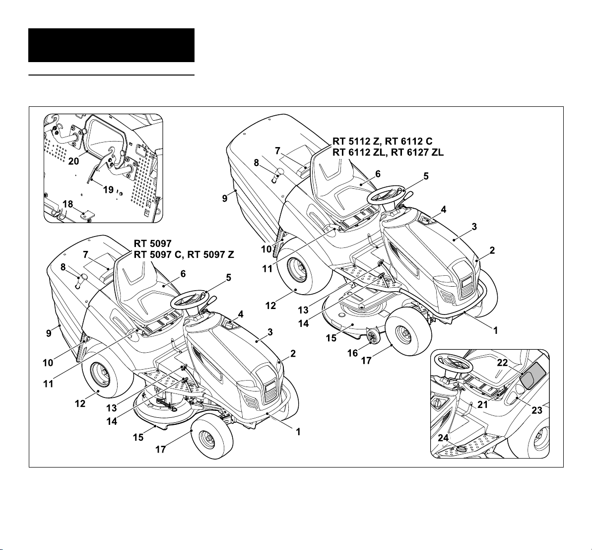
3. Machine overview
3.1 Ride-on mower
6
0478 192 9809 A - EN

1 Bumper
2 Headlamp
3 Engine hood
4 Tank cap
5 Steering wheel
6 Driver's seat
7 Grass catcher box handle with grass
catcher box release lever
8 Grass catcher box emptying lever
9 Grass catcher box
10 Gearbox freewheel lever
11 Cutting height adjustment lever
12 Rear wheel
13 Brake pedal
14 Drive pedal (driving speed)
15 Mowing deck
16 Gauge wheels
17 Front wheel
18 Trailer hitch
19 Level sensor (grass catcher box)
20 Discharge chute
21 Driver's seat adjustment lever
22 Battery compartment
23 Beverage compartment
24 Reverse mowing safety switch
ENES
PTEL
0478 192 9809 A - EN
7
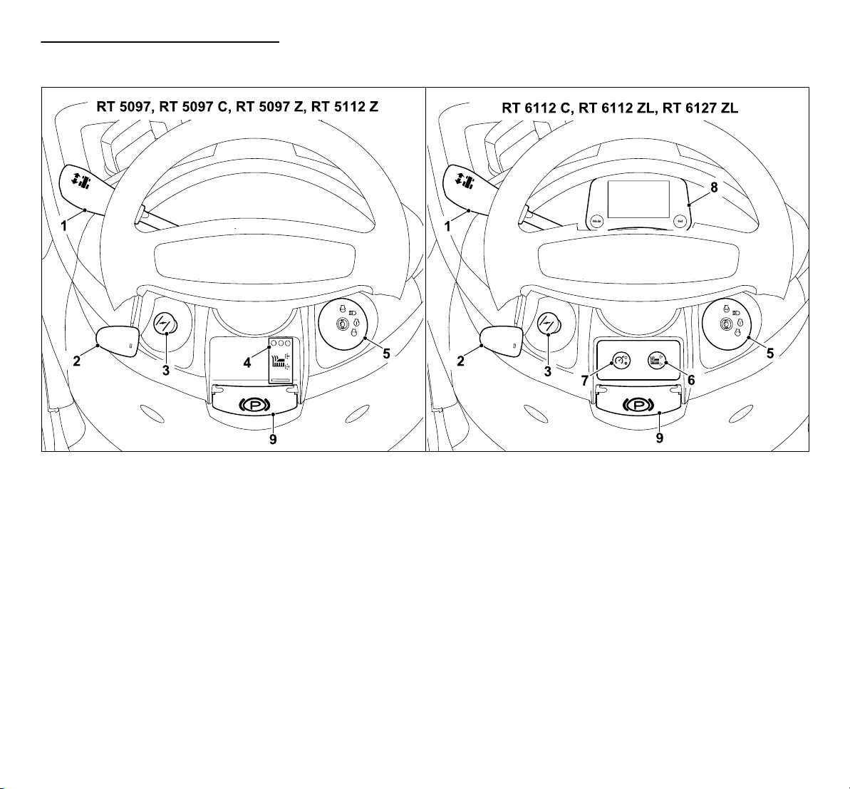
3.2 Dashboard
1 Driving direction selector lever
(forwards/reverse)
(Ö 8.9)
2 Throttle lever with integrated
choke function
(RT 5097, RT 5097 C, RT 6112 C)
(Ö 8.2)
2 Throttle lever
(RT 5097 Z, RT 5112 Z,
RT 6112 ZL, RT 6127 ZL)
(Ö 8.3)
3 Choke knob
(RT 5097 Z, RT 5112 Z,
RT 6112 ZL, RT 6127 ZL)
(Ö 8.4)
8
4 Mowing deck switch
(RT 5097, RT 5097 C, RT 5097 Z,
RT 5112 Z)
(Ö 8.5)
5 Ignition lock with light switch
(Ö 8.1)
6 Mowing deck button
(RT 6112 C, RT 6112 ZL,
RT 6127 ZL)
(Ö 8.6)
7 Cruise control button
(RT 6112 ZL, RT 6127 ZL)
(Ö 8.7)
8 Display with control buttons
(RT 6112 C, RT 6112 ZL,
RT 6127 ZL)
(Ö 10.)
9 Parking brake lever
(Ö 8.14)
0478 192 9809 A - EN
4. For your safety
4.1 General
These safety regulations must
be observed when working with
the machine.
Read the entire instruction
manual before using the
machine for the first time. Keep
the instruction manual in a safe
place for future reference.
Observe the operating and maintenance
instructions contained in the separate
engine instruction manual.
These safety precautions are essential for
your safety, however the list is not
exhaustive. Always use the machine in a
reasonable and responsible manner and
be aware that the user is responsible for
accidents involving third parties or their
property.
Risk of death from suffocation!
Packaging material is not a toy danger of suffocation! Keep
packaging material away from
children.
Only give or lend the machine, including
any accessories, to persons who are
familiar with this model and how to operate
it. The instruction manual forms part of the
machine and must always be provided to
persons borrowing it.
Make sure that the user is physically,
sensorily and mentally capable of
operating the machine and working with it.
If the user is physically, sensorily or
mentally impaired, the machine must only
be used under supervision or following
instruction by a responsible person.
Make sure that the user is of legal age or
being trained under supervision in a
profession in accordance with national
regulations.
The machine must only be operated by
persons who are well rested and in good
physical and mental condition. If your
health is impaired, you should consult your
doctor to determine whether working with
the machine is possible. The machine
should not be operated after the
consumption of alcohol, drugs or
medications which impair reactions.
Caution – risk of accident!
The ride-on mower is only intended for
mowing lawns; its use for other purposes
is not permitted.
The machine must only be equipped with
original STIHL accessories. These enable
further applications. Information is
available from your STIHL specialist
dealer.
Due to the physical danger to the user or
other persons, the machine must not be
used, for example, for the following
applications (incomplete list):
– for cutting creepers,
– for shredding or chopping tree or hedge
cuttings,
– for clearing paths (vacuuming,
blowing),
– for snow clearing using the mowing
deck,
– for the care of lawn roofs,
– for levelling earth mounds, e.g. mole
hills.
– for transporting clippings, except in the
grass catcher box intended for this
purpose.
The machine is not approved for use on
public roads.
The carrying of persons (especially
children) and animals is not permitted.
Never climb onto the mowing deck, and in
particular the gauge wheels.
Objects must not be transported on the
machine, but only with the aid of a trailer
approved by STIHL (accessory). The
weight limits must be observed. (Ö 13.11)
Particular care is required during use in
public green spaces, parks, sports fields,
along roads and in agricultural and forestry
businesses.
The machine must not be used for sporting
or competitive events.
For safety reasons, any modification to the
machine, except the proper installation of
accessories or attachments approved by
STIHL is forbidden and results in voiding of
the warranty cover. Information regarding
approved accessories and attachments
can be obtained from your STIHL
specialist dealer.
In particular, any tampering with the
machine which increases the power
output, engine speed or driving speed is
forbidden.
The machine is equipped with electronics
which must not be modified or removed.
For safety reasons, the machine software
must never be modified or tampered with.
Caution! Danger to health due
to vibrations. Excessive
exposure to vibrations can
result in damage to the
cardiovascular or nervous system,
ENES
PTEL
0478 192 9809 A - EN
9

particularly in persons with cardiovascular
problems. Please consult a physician if
you experience symptoms that may have
been caused by vibrational loads.
Symptoms of this kind principally affect the
fingers, hands or wrists and include
(incomplete list):
– numbness,
– pain,
– muscular weakness,
– skin discolouration,
– unpleasant tingling sensation.
Hold the handlebar tightly, but not tensed,
with both hands in the designated
locations during operation.
Plan your working times so that more
severe physical strains over a longer
period are avoided.
4.2 Training – learning to use the machine
Make sure that you are familiar with the
controls and operation of the machine. In
particular, the user must know how the
work tools and engine can be stopped
quickly.
The machine must only be used by
persons who have read the instruction
manual and are familiar with operation of
the machine. The user should seek expert
and practical instruction prior to initial
operation. The user must receive
instruction on safe use of the machine
from the vendor or another expert.
During this instruction, the user should be
made aware
– that the utmost care and concentration
are required for working with the
machine.
– that a ride-on mower which is sliding
down a slope cannot be brought under
control by applying the brake.
The main causes for the loss of control
over the ride-on mower include:
– inadequate adhesion of the wheels,
– driving too fast,
– inappropriate braking,
– incorrect use (sport events, etc.),
– inadequate knowledge of the effects
associated with ground conditions,
especially on slopes (see section "For
your safety", "Working on slopes"),
– incorrect attachment of loads and poor
load distribution.
Residual risks persist even if you operate
the machine according to the instructions.
4.3 Transporting the ride-on mower
On account of its own weight, the ride-on
mower can cause severe crush injuries.
Particular care must be taken when
loading or unloading the ride-on mower
onto/from a vehicle or trailer for transport
purposes.
This ride-on mower must not be towed. For
transporting on public roads, a suitable
vehicle or a suitable trailer must be used.
During transport, secure the ride-on
mower to a load floor as described in this
instruction manual. Always engage the
parking brake. (Ö 16.)
Prior to transporting or storage, disengage
the drive to the mowing blade or
attachments.
When transporting the machine, always
observe regional legislation, especially
regarding load security and the transport
of objects on load floors.
Allow the machine, in particular the engine
and muffler, to cool down completely after
loading and before further transport. The
load floor and the area around the muffler
and engine must be kept free of
combustible materials such as straw,
leaves or dry grass residues.
4.4 Refilling the tank – handling petrol
Danger to life!
Petrol is poisonous and extremely
inflammable.
Petrol must only be stored in appropriate,
tested containers (canisters). Always
screw on the fuel tank and canister caps
properly and tightly. Defective caps must
be replaced for safety reasons.
Keep petrol away from sparks,
naked flames, pilot lights, heat
sources, and other ignition
sources. Do not smoke!
Refill the tank out-of-doors and do not
smoke during refilling.
Before refilling the tank, stop the engine
and allow it to cool.
Refilling with petrol must be performed
before the engine is started. When the
engine is running or is hot, the tank cap
must not be removed and the tank must
not be refilled with petrol.
10
0478 192 9809 A - EN
Open the fuel tank cap slowly and
carefully. Wait for pressure compensation
and only then remove the tank cap
completely.
Use a suitable funnel or filling pipe for
refilling the tank, so that no fuel can spill
onto the engine and housing or the lawn.
Do not overfill the fuel tank!
To give the fuel room to expand,
never fill the fuel tank past the
lower edge of the filler neck.
Observe the additional
instructions in the engine
instruction manual.
If petrol is spilled, the engine
must only be started after the petrolcontaminated area has been cleaned. All
attempts at starting must be avoided until
the petrol fumes have dispersed (wipe
dry).
Any spilt fuel must be wiped up
immediately.
Clothing must be changed if it comes into
contact with petrol.
Following each refilling of the tank, the fuel
tank cap must be properly screwed on and
tightened. The machine must not be
operated without the original tank cap.
For safety reasons, the fuel line, fuel tank,
tank cap and connections must be
checked regularly for damage, ageing
(brittleness), firm seating and leaks.
Replace if necessary (consult a specialist
dealer; STIHL recommends STIHL
specialist dealers).
If it is necessary to drain the tank, this must
be done out of doors.
Never use beverage bottles or similar for
disposal or storage of fuels and lubricants.
Persons, particularly children, could be
tempted to drink out of them.
Never store the machine with petrol in the
tank inside a building. The resulting petrol
fumes could come into contact with naked
flames or sparks and could be ignited.
Do not leave the machine and the fuel tank
close to heating systems, radiant heaters,
welding equipment and other sources of
heat. Explosive hazard!
4.5 Clothing and equipment
Always wear sturdy footwear
with high-grip soles when
working. Never work barefoot
or, for example, in sandals.
Always wear long trousers and tight-fitting
clothing when operating the machine.
Never wear loose clothes which may
become caught on moving parts (control
levers) – do not wear jewellery, ties or
scarves.
Also always wear sturdy gloves
and tie up and secure long hair
(headscarf, cap, etc.) when
performing maintenance and
cleaning work or when transporting the
machine.
Wear suitable safety glasses
when sharpening the mowing
blade.
Noise is produced when
working. Noise can damage the
hearing.
Wear hearing protection.
4.6 Before operation
Make sure that only persons who are
familiar with the instruction manual are
permitted to use the machine.
Check the fuel system (particularly visible
parts such as e.g. tank, tank cap, hose
connections) before operating the
machine. In the event of any leaks or
damage, do not start the engine – fire
hazard!
Have the machine repaired by a specialist
dealer prior to operation.
Observe the local regulations regarding
permitted operating times for gardening
power tools with combustion engines or
electric motors.
Carefully inspect the complete area on
which the machine is to be used and
remove any stones, sticks, wires, bones
and other foreign objects which could be
thrown up by the machine. Obstacles (e.g.
tree stumps, roots) can be easily
overlooked in long grass.
For this reason, mark all foreign objects
(obstacles) which are hidden in the lawn
and cannot be removed before
commencing work with the machine.
All faulty, worn or damaged parts must be
replaced before using the machine.
Replace any illegible or damaged danger
signs and warnings on the machine. Your
STIHL specialist has a supply of
replacement stickers and all the other
spare parts.
Never use the machine with damaged
safety devices or with safety devices
removed.
The braking function must be checked
before each use. (Ö 13.5)
Before each use, check whether:
ENES
PTEL
0478 192 9809 A - EN
11
– the cutting tool and the entire cutting
unit (mowing blade, blade clutch, blade
brake, retaining pin, mowing deck
housing) are in good condition.
Particularly check for secure fastening,
damage and wear.
– the tank cap is securely attached.
– the tank and fuel-carrying parts as well
as the tank cap are in good condition.
– the safety devices are in good condition
and function correctly.
– the tyres (inflation pressure, damage,
wear) and frame are in good condition.
Check that all screw connections are
securely fastened. In particular, all
maintenance operations listed in the
maintenance schedule under the
heading "Before each use" must be
carried out. (Ö 15.1)
If necessary, consult a specialist dealer.
STIHL recommends STIHL specialist
dealers.
4.7 Working with your machine
Never work in the vicinity of
other persons, particularly
children, or animals. Ensure
that the grass is never
discharged in the direction of other
persons.
Do not operate the machine in the rain or
during thunder storms, particularly when
there is a risk of lightning strike.
Exhaust gases:
Danger to life through poisoning!
In the case of nausea, headache,
impaired vision (e.g. decreasing
field of view) hearing disorder,
dizziness, decreasing power of
concentration, stop working
immediately. These symptoms may
be caused by excessively high
exhaust gas concentrations.
The machine generates
poisonous exhaust gases when
the engine is running. The
gases contain poisonous
carbon monoxide, a colourless and
odourless gas, as well as other pollutants.
The engine must never be operated in
closed or poorly ventilated spaces.
Starting:
The machine must only be started from the
driver's seat.
Start the machine on level ground, not on
a slope.
The engine may only be started in a well
ventilated working area, sufficient
ventilation must be ensured, particularly in
garages.
Before starting the engine, disengage the
cutting tool, attachments and drive and
press down the brake pedal fully.
When starting, it must be ensured that
there is sufficient clearance between the
feet and the cutting tool.
Never start the engine by short-circuiting
the starter terminal. If the normal starter
circuit is bypassed, the ride-on mower may
suddenly be set in motion.
Never start the engine if the smell of petrol
can be detected – Explosive hazard!
Working:
Warning – Risk of injury!
Observe the working
area of the mowing
blade. Never put hands
or feet on or underneath
rotating parts. Never touch the
rotating mowing blade. Always
keep away from the discharge
opening. An adequate safety
distance must always be
maintained.
Only work during the day or with good
artificial light.
When driving off the lawn or when not
mowing, the mowing blades must be
disengaged and the mowing deck must be
set to the highest cutting position.
Objects hidden in the turf (lawn sprinkler
systems, posts, water valves, foundations,
electrical wires, etc.) must be avoided.
Never run over any such foreign objects.
Always hold the steering wheel firmly with
both hands when driving.
Particular care must be taken when driving
on lawns and other uneven surfaces, as
the steering wheel can be made to turn
due to holes, mounds, impacts, etc.
Risk of injury to hands and fingers!
If, during operation, a defect in the tank,
tank cap or in the fuel-carrying
components (fuel lines) is detected, the
engine must be stopped immediately. A
specialist dealer must then be contacted.
STIHL recommends STIHL specialist
dealers.
Beware of depressions (holes) in the
terrain and other invisible points of danger.
Obstacles can be easily overlooked in long
grass.
12
0478 192 9809 A - EN

Always drive at a reasonable speed.
Use the machine with great care when
working near slopes, terraces, ditches and
embankments. In particular, ensure that
you maintain sufficient distance to such
danger areas.
Particular care must be taken at points of
poor visibility, bushes, trees and other
obstacles, behind which persons,
especially children, or animals may be
hidden.
Bring the ride-on mower to a standstill
immediately and stop the mowing blade if
someone moves into the area to be mown.
Always monitor the area in front of the
vehicle. Beware of obstacles, in order to
be able to evade them in time.
Before reversing, always check the area
behind the ride-on mower and, if present,
disengage the attachment. Never mow in
reverse, if it is not absolutely necessary.
When mowing in reverse, take particular
care and before beginning to mow,
thoroughly check the entire area behind
the ride-on mower.
When working together in a group, always
inform the others in advance of what you
intend to do. Maintain a safety distance!
The vehicle speed must be reduced before
each change of direction, so that the user
retains control of the machine at all times
and also that the ride-on mower cannot tip
over.
When operating near to roads and when
crossing roads, other road users must be
taken into account.
Take particular care when mowing near
roads, cycle paths and footpaths. Objects
which are thrown up by the mower can
cause severe injury and damage.
Only empty the grass catcher box from the
driver's seat.
Before emptying the grass catcher box,
always disengage the mowing blades and
wait until they have come to a standstill.
When operating the ride-on mower with
attachments, always follow the
instructions and safety regulations
supplied with the attachments.
Switch off the drive, stop the engine and
wait until the mowing blades have come to
a complete standstill, engage the parking
brake and remove the ignition key:
– when abandoning or when transporting
the machine.
– before remedying blockages, including
those in the discharge chute.
– before checking, cleaning or working on
the ride-on mower.
– if the mowing blades have hit an
obstacle.
Inspect the machine and the cutting tool
for damage and have any necessary
repairs performed before re-starting.
Additionally check the installation
position of the mowing blades on the
models RT 5112 Z, RT 6112 C,
RT 6112 ZL, RT 6127 ZL – the mowing
deck must not be engaged if the angle
of the blades relative to each other is
not as specified in the section "Mowing
blade maintenance". (Ö 15.13)
– if the machine begins to vibrate
excessively. It must be checked
immediately.
Stop the engine and wait until the mowing
blades have come to a complete standstill:
– Before filling with fuel.
– Before removing the grass catcher box.
– Before opening the engine hood.
Driving with cruise control:
Activating cruise control in the wet or
under adverse ground conditions as well
as when pulling loads increases the
accident risk.
When cruise control is switched off, the
ride-on mower brakes abruptly.
Cruise control is an aid that provides
assistance when driving. The
responsibility for the driving speed and for
timely braking always lies with the user.
Cruise control does not react to obstacles
or to altered ground conditions. If an
obstacle cannot be avoided at the set
driving speed, cruise control must be
switched off.
Due to the increased risk of accident,
cruise control must not be used:
– In situations which do not permit driving
at constant speed (e.g. adverse ground
conditions due to wet conditions or on
slopes).
– On slippery surfaces. The wheels may
lose their grip and the vehicle can skid.
– If visibility is poor (e.g. due to fog, heavy
rain or at night).
Working on slopes:
Slopes are one of the major causes of
accidents in which control over the ride-on
mower is lost causing it to tip over, which
can result in severe or even fatal injuries.
There is no "safe" slope! Driving on grassy
slopes requires special concentration.
For safety reasons, the machine must not
be used on slopes with an inclination of
more than 10° (17.6 %). Risk of injury!
ENES
PTEL
0478 192 9809 A - EN
13
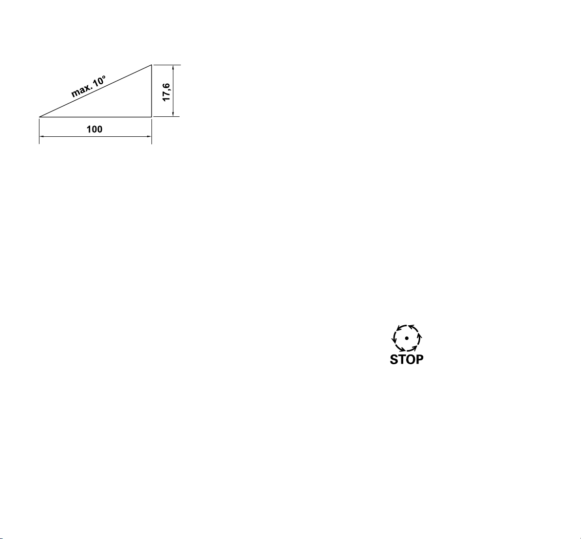
A slope inclination of 10° corresponds to a
vertical height increase of 17.6 cm for a
100 cm horizontal distance.
In order to ensure an adequate oil supply
for the engine, the information in the
accompanying engine instruction manual
must be additionally observed when using
the machine on slopes.
If you cannot drive up the slope in reverse
or if you have doubts regarding safety, you
should not drive on the slope.
Starting off or stopping on a gradient must
be avoided.
Do not use the machine in places (slopes,
ditches, etc.) where the ride-on mower can
tip over or slide. The danger of tipping over
or sliding increases if the ground is soft or
damp.
Slopes must be driven on in a longitudinal
direction. Driving transversely increases
the danger of tipping over.
Do not change speed or direction abruptly
when driving on slopes. Work in this type
of situation requires calm, cautious and
even operation of the ride-on mower.
Changes of direction on slopes must be
avoided. Only turn on slopes if this is
unavoidable. If possible, drive slowly and
in a large curve in the down-slope
direction.
Do not mow wet grass, particularly on
slopes, as wheel grip is reduced on wet
grass. The ride-on mower could slide and
become uncontrollable for the user.
The gearbox must never be disengaged
via the gearbox freewheel when driving on
slopes.
Special care must be taken when
operating attachments on slopes (altered
weight distribution of the machine).
If the wheels should start to slip or if the
vehicle becomes stuck in the up-slope
direction when driving on an incline, the
mowing blades or the attachment must be
disengaged. Then leave the slope by
driving slowly downhill in a straight line.
Never try to stabilise the ride-on mower by
pressing on the ground with your foot.
The weight of the grass catcher box
increases the danger of the ride-on mower
tipping over, particularly when it is full.
Never empty or lift the grass catcher box
on an incline.
Pulling loads:
Particular care must be taken when pulling
loads, in order to prevent the risk of severe
or even fatal injuries due to the ride-on
mower tipping over.
Only use accessories approved by STIHL
for transporting objects. Transportation on
the ride-on mower, in or on the grass
catcher box is not permitted.
For pulling loads, use only the trailer hitch.
Loads must never be attached to the axle
housing or to another point above the
trailer hitch.
Please refer to the section "Pulling loads"
for information on pulled and coupling
loads. (Ö 13.11)
Exceeding the specified pulled load is
dangerous and may result in damage to
the machine (engine, gearbox, etc.).
When transporting on slopes, the loads
must be adapted so that safe handling of
the ride-on mower (e.g. braking, change of
direction, starting off) is ensured at all
times.
Check whether loads are properly and
securely fastened. Use lashing straps for
securing loads.
Ensure balanced load distribution.
Use suitable additional weights
(accessories) if this is described in the
instruction manual for the attachment.
Do not execute tight curves. Particular
care must be taken when reversing.
Do not change speed or direction abruptly.
Stopping and parking:
The ride-on mower must only be parked on
a level surface.
Make sure that the ride-on mower has
come to a complete standstill before you
dismount.
Beware of the cutting tool
running on for several seconds
before coming to a standstill.
Before leaving the driver’s seat,
disengage the mowing blades
or the drive to the attachments, lower the
mowing deck and all attachments, set all
control levers to the neutral position,
engage the parking brake, stop the engine
and remove the ignition key.
Keep the ignition key in a place where only
authorised persons can access it.
14
0478 192 9809 A - EN

4.8 Maintenance and repairs
Before beginning cleaning,
adjustment, repair and
maintenance operations, park
the machine on firm, level ground, engage
the parking brake, stop the engine, allow it
to cool down and remove the ignition key.
Allow the machine to cool down before
working on or around the engine, exhaust
manifold or muffler; this also applies in
particular to all maintenance operations on
the mowing deck. Temperatures of 80 °C
and above can be reached. Danger of
burns:
Direct contact with engine oil can be
dangerous. Engine oil must not be spilled.
STIHL recommends leaving the task of
topping up engine oil or performing engine
oil changes to a STIHL specialist dealer.
Cleaning:
Following operation, the entire ride-on
mower and the attachments must be
cleaned. In particular, all grass residues
must be removed because the moisture
these contain leads to damage in the long
term.
STIHL does not recommend the use of
high-pressure cleaners. (Ö 15.2)
Remove the mowing deck for cleaning
operations. Never clean the mowing deck
using water under high pressure (e.g.
garden hose) or by engaging the mowing
deck in puddles of water.
Never drive close to an edge or a ditch for
the purpose of cleaning (e.g. the frame of)
the ride-on mower.
In order to prevent fire hazards, keep the
engine, cooling ribs, battery compartment,
area around the fuel tank and exhaust free
from grass, leaves or escaping oil (or
grease).
Always clean the grass catcher box.
Maintenance operations:
Only maintenance operations described in
this instruction manual may be carried out.
Have all other work performed by a
specialist dealer.
If you do not have the necessary expertise
or auxiliary equipment, please always
contact a specialist dealer.
STIHL recommends that you have
maintenance operations and repairs
performed exclusively by a STIHL
specialist dealer.
STIHL specialist dealers regularly attend
training courses and are provided with
technical information.
Only use tools, accessories or
attachments approved for this machine by
STIHL or technically identical parts.
Otherwise, there may be a risk of
accidents resulting in personal injury or
damage to the machine. If you have any
questions, please consult a specialist
dealer.
The characteristics of original STIHL tools,
accessories and spare parts are optimally
adapted to the machine and the user's
requirements. Genuine STIHL spare parts
can be recognised by the STIHL spare
parts number, by the STIHL lettering and,
if present, by the STIHL spare parts
symbol. On smaller parts, only the symbol
may be present.
The ride-on mower and all attachments
should be inspected once annually by a
specialist dealer. (Ö 15.1)
Always keep warning and information
stickers clean and readable. Damaged or
missing stickers must be replaced by new,
original plates from your STIHL specialist
dealer. If a component is replaced with a
new component, ensure that the new
component is provided with the same
stickers.
For safety reasons, fuel-carrying
components (fuel line, fuel cock, fuel tank,
tank cap, connections, etc.) must be
checked regularly for damage and leaks
and replaced by a technician if necessary
(STIHL recommends STIHL specialist
dealers).
Before starting work on or near electrical
components, the negative (–) cable must
be disconnected from the battery.
The machine is equipped with numerous
safety devices. These devices must not be
removed or modified (bypassed, etc.) and
must be checked at regular intervals.
Operations on the safety devices must
only be carried out by a technician. STIHL
recommends STIHL specialist dealers for
this purpose.
Be aware that moving one cutting tool
results in the turning of the other cutting
tools.
Ensure that all nuts, pins and screws,
especially the blade fastening screws, are
securely tightened, so that the machine is
in a safe operating condition.
For safety reasons, worn or damaged
parts must be replaced immediately.
Check the grass catcher unit (e.g. grass
catcher box, discharge chute) regularly for
wear, damage or loss of functionality.
Particular care is required when working
under the machine, due to the weight of
the ride-on mower. Consult your specialist
ENES
PTEL
0478 192 9809 A - EN
15

dealer for this purpose; STIHL
recommends STIHL specialist dealers.
They will have a workshop pit or a
hydraulic working platform.
Check the secure fastening of the front
and rear wheels.
Always maintain the ride-on mower and
the attachments in perfect operating
condition. All safety devices must be
present and be in perfect operating
condition.
Ensure that the tyres have the correct tyre
pressures. The tyre pressures specified in
the instruction manual must not be
exceeded.
Only perform work on the mowing blades
when wearing thick work gloves and
exercising extreme care.
Check the function of the brakes at
regular, short intervals and, if necessary,
have the required adjustments or
maintenance operations performed by a
technician. STIHL recommends STIHL
specialist dealers.
Electrical system and battery:
In order to prevent sparks due to short
circuiting, the negative (–) cable must
always be disconnected from the battery
first and reconnected last.
Never smoke when working on
the battery. Sparks, naked
flames and other heat sources
must be kept away from the
battery.
Particular care is necessary when using
battery jump leads. Observe the relevant
instructions in order to prevent damage to
the ride-on mower (in particular, actuate
the starter for a maximum of 10 seconds).
(Ö 13.2)
When charging the battery using another
charging system, observe the instructions
in section "Charging the battery".
(Ö 15.21)
Never open the battery and do not drop it.
Always charge the battery in an enclosed,
well-ventilated room which is dry and
weather-protected.
Do not short circuit the battery
connections.
Deformed or faulty (leaking) batteries must
not be used and must be replaced and
disposed of in an environmentally-friendly
manner. Observe country-specific
legislation.
Fluid may escape from faulty batteries.
Avoid contact! In the case of inadvertent
contact, rinse with water. Seek medical
attention if the fluid contacts the eyes.
Escaping battery fluid can cause skin
irritation and burns.
Visually inspect the battery connection
cables for damage at regular intervals.
Have damaged cables replaced by a
technician.
Never bypass the fuses. Never use a fuse
with a value that differs from the specified
rating (ampere).
4.9 Storage for prolonged periods without operation
Allow the engine to cool before storing the
machine in an enclosed space.
Store the ride-on mower with empty fuel
tank and the fuel reserve in a lockable and
well-ventilated room.
Never store the machine with petrol in the
fuel tank inside a building in which the
petrol fumes could come into contact with
naked flames or sparks.
If the tank has to be emptied
(e.g. immobilisation before the winter
break), the fuel tank must be emptied out
of doors only (empty the tank by running
the engine out of doors, for example).
Store the machine in good operational
condition.
The ignition key must always be removed
and kept in a safe place, to prevent
unauthorised or improper use by children
or other persons.
Thoroughly clean the ride-on mower
before storage (e.g. winter break). Dry
grass residues and leaves near to the
muffler may ignite. Danger of
combustion!
Allow the machine to cool down
completely before covering it.
Perform all the necessary maintenance
operations before storing the machine.
(Ö 15.1)
The battery cables must be disconnected if
the ride-on mower is immobilised for
longer periods. STIHL recommends
removing the battery and storing it in a dry
and locked place. (Ö 15.19)
Ensure that batteries are protected from
unauthorised use (e.g. by children).
4.10 Disposal
Waste products such as used engine oil or
fuel, used lubricants, filters, batteries and
similar wearing parts can be harmful to
16
0478 192 9809 A - EN

people, animals and the environment, and
must consequently be disposed of
properly.
Consult your recycling centre or your
specialist dealer for information on the
proper disposal of waste products. STIHL
recommends STIHL specialist dealers.
Ensure that old machines are properly
disposed of. Render the machine
unusable prior to disposal. In order to
prevent accidents, ensure that you remove
the ignition key, the battery and the ignition
lead on the engine.
Risk of injury due to the mowing blade!
Always store an old ride-on mower in a
safe place prior to scrapping. Ensure that
the machine and particularly the mowing
blades are kept out of the reach of
children.
The battery must be disposed of
separately from the machine. Ensure that
batteries are disposed of safely and in an
environmentally friendly manner.
5. Description of symbols
Risk of injury:
Remove the ignition key before performing
any work on the cutting tool or
maintenance and cleaning work.
Caution:
Keep a safe distance.
Caution:
Beware of objects being thrown out when
the engine is running – work with grass
catcher box or deflector (special
accessory).
Caution:
Never reach into the working area of the
mowing blades when the engine is
running.
Risk of injury:
Do not stand on the mowing deck.
Danger of burns!
Do not touch hot surfaces. Engine
components, especially mufflers, can
become extremely hot.
ENES
PTEL
Caution:
Read and follow the instruction manual
and the safety instructions before initial
use.
0478 192 9809 A - EN
Risk of injury:
Do not drive or mow on slopes with an
inclination greater than 10° (17%).
Danger of tipping over!
Risk of injury:
Keep other persons out of the danger
area.
17

6. Standard equipment
Item Designation Qty.
A Basic unit 1
B Grass catcher box 1
C Ignition key 2
Instruction manual 1
Engine instruction manual 1
18
0478 192 9809 A - EN

7. Operations prior to initial use
Warning!
Prior to all operations on the ride-on
mower, carefully read and observe
the section "For your safety". (Ö 4.)
● Check engine oil filling level. (Ö 15.8)
● Fill fuel tank. (Ö 13.1)
● Open fuel cock. (Ö 15.7)
● Optimise tyre pressure. (Ö 15.16)
8. Controls
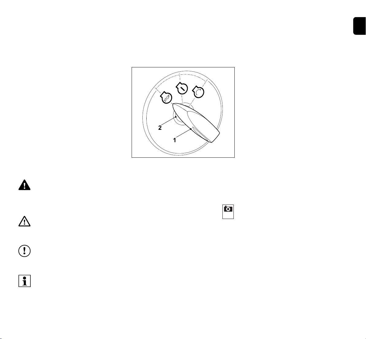
8.1 Ignition lock with light switch
The ignition lock serves to start
and stop the engine and to switch
the headlamps on and off.
Avoid damage to the machine.
The ignition key can only be
inserted and removed in the
"engine off" position.
The ignition lock can only be
operated with the appropriate
ignition key – never use a
screwdriver or other such object.
Insert ignition key (1) in ignition lock (2).
The following four positions can be
selected by turning the ignition key:
Engine off:
The engine is switched off or will
be stopped. The lights are
switched off and the ignition key can be
removed.
Lights on (operation with
lights):
Running engine:
The lights are switched on and the engine
continues to run.
Engine off:
The lights are switched on.
Ignition on/engine running:
The ignition is switched on and
the lights are switched off.
Following starting, the ignition key returns
automatically to this position and the
engine continues to run.
Start engine:
When all safety-relevant points
for starting are fulfilled and the
ignition key is turned to this
position, the engine starts.
On releasing the ignition key, it returns
automatically to the "engine running"
position.
Note
When the engine is stopped, a
signal tone is activated after 20
seconds in the "lights on" and
"ignition on" positions. The acoustic
signal indicates that the battery is
being discharged. To deactivate the
signal tone, turn the ignition key to
the "engine off" position or start the
engine.
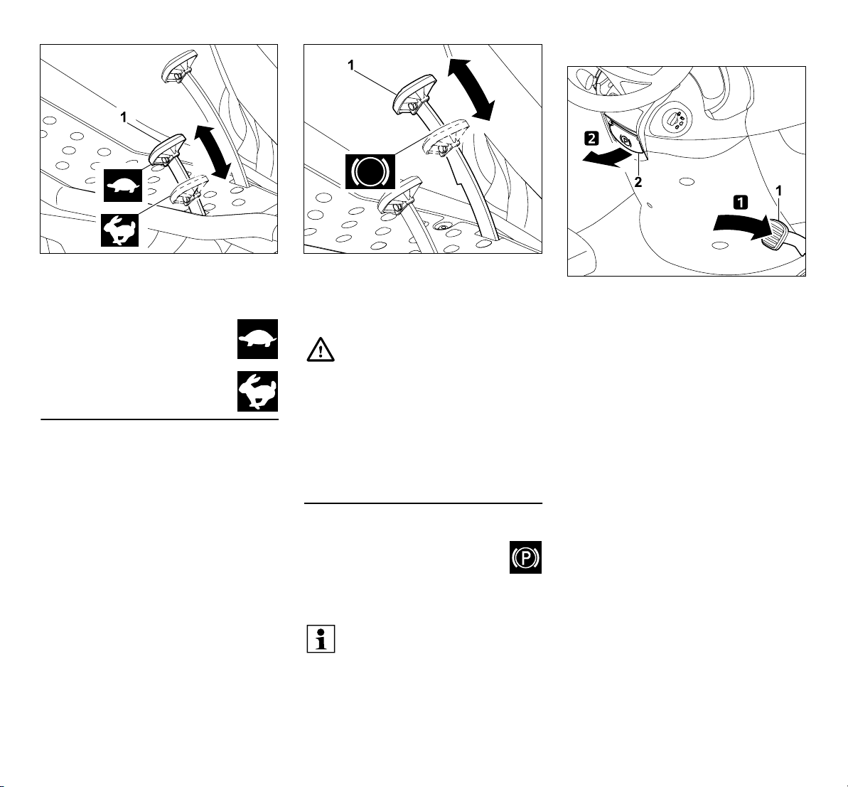
8.2 Throttle lever with choke function (RT 5097, RT 5097 C, RT 6112 C)
To start a cold engine, move the throttle
lever on the models RT 5097, RT 5097 C
and RT 6112 C to the choke position.
Do not use the choke when starting
a warm engine (throttle lever in
MAX position).
Deactivate the choke as soon as
the engine is running.
Never move the throttle lever to the
choke position when the engine is
running.
ENES
PTEL
0478 192 9809 A - EN
19

Choke position:
If the throttle lever (1) is pushed
downwards or upwards, the engine speed
changes and, if the mowing deck is
engaged, the speed of the mowing blades
is changed.
MAX position:
If the throttle lever (1) is moved forwards
towards the MAX marking, the engine
speed is increased.
MIN position:
If the throttle lever (1) is pushed back
towards the MIN marking, the engine
speed is reduced.
Push throttle lever (1) fully forwards into
the choke position (note detent).
Setting the engine speed:
Move the throttle lever to the MAX
position during mowing and to start
the engine.
8.3 Throttle lever (RT 5097 Z, RT 5112 Z, RT 6112 ZL, RT 6127 ZL)
Setting the engine speed:
Move the throttle lever to the MAX
position during mowing and to start
the engine. To start a cold engine,
also actuate the choke knob.
8.4 Choke knob (RT 5097 Z, RT 5112 Z, RT 6112 ZL, RT 6127 ZL)
The models RT 5097 Z, RT 5112 Z,
RT 6112 ZL, RT 6127 ZL are equipped
with a choke knob for starting a cold
engine.
Do not use the choke when starting
a warm engine.
As soon as the engine is running,
push the choke knob back to its
initial position.
Never activate the choke when the
engine is running.
20
0478 192 9809 A - EN

Activating the choke:
Before starting, pull out the choke knob (1)
to the stop.
Deactivating the choke:
● Press in the choke knob to the stop.
8.5 Mowing deck switch (RT 5097, RT 5097 C, RT 5097 Z, RT 5112 Z)
The mowing deck switch can be used to
engage the mowing deck when the engine
is running and with due regard to all safety
devices (Ö 12.).
Avoid damage to the machine!
Do not engage the mowing blade in
tall grass or when set to the lowest
cutting level.
Only activate the mowing deck at
maximum speed (throttle lever in
MAX position).
Engaging the mowing deck:
Press the top of the mowing deck
switch (1) to the stop.
Disengaging the mowing deck:
Press the bottom of the mowing deck
switch (1) to the stop.
If necessary, the electronics can be
programmed so that the mowing
deck is automatically disengaged
when the grass catcher box is full.
(Ö 13.8)
8.6 Mowing deck button (RT 6112 C, RT 6112 ZL, RT 6127 ZL)
The mowing deck button can be
used to engage the mowing deck
when the engine is running and
with due regard to all safety devices
(Ö 12.).
Avoid damage to the machine!
Do not engage the mowing blade in
tall grass or when set to the lowest
cutting level.
Only activate the mowing deck at
maximum speed (throttle lever in
MAX position).
Engaging the mowing deck:
Press the mowing deck button (1) for at
least 1 second. The mowing deck is
engaged as soon as the "mowing deck
active" symbol (2) appears on the display.
Disengaging the mowing deck:
● Press the mowing deck button. The
mowing deck is disengaged as soon as
the "mowing deck active" symbol
disappears from the display.
ENES
PTEL
0478 192 9809 A - EN
21

If necessary, the electronics can be
programmed so that the mowing
deck is automatically disengaged
when the grass catcher box is full.
(Ö 13.8)
8.7 Cruise control button (RT 6112 ZL, RT 6127 ZL)
The cruise control button sets the
current driving speed when driving.
Although the "cruise control active"
symbol appears on the display
when reversing after the cruise
control button is pressed, cruise
control remains deactivated for
safety reasons.
The cruise control button has no
function on the model RT 6112 C.
Activating cruise control:
Select the required driving speed and
press the cruise control button (1) for at
least 1 second. Cruise control is activated
as soon as the "cruise control active"
symbol (2) appears on the display. The
drive pedal is locked in place and the
current driving speed is maintained. The
foot can be removed from the drive pedal.
Deactivating cruise control:
Risk of injury!
Place the foot on the drive pedal
prior to deactivating the cruise
control in order to prevent the drive
pedal from springing back, thereby
preventing abrupt braking of the
ride-on mower.
● Press the cruise control button, leave
the driver's seat or actuate the brake
pedal.
Cruise control is deactivated as soon as
the "cruise control active" symbol
disappears from the display.
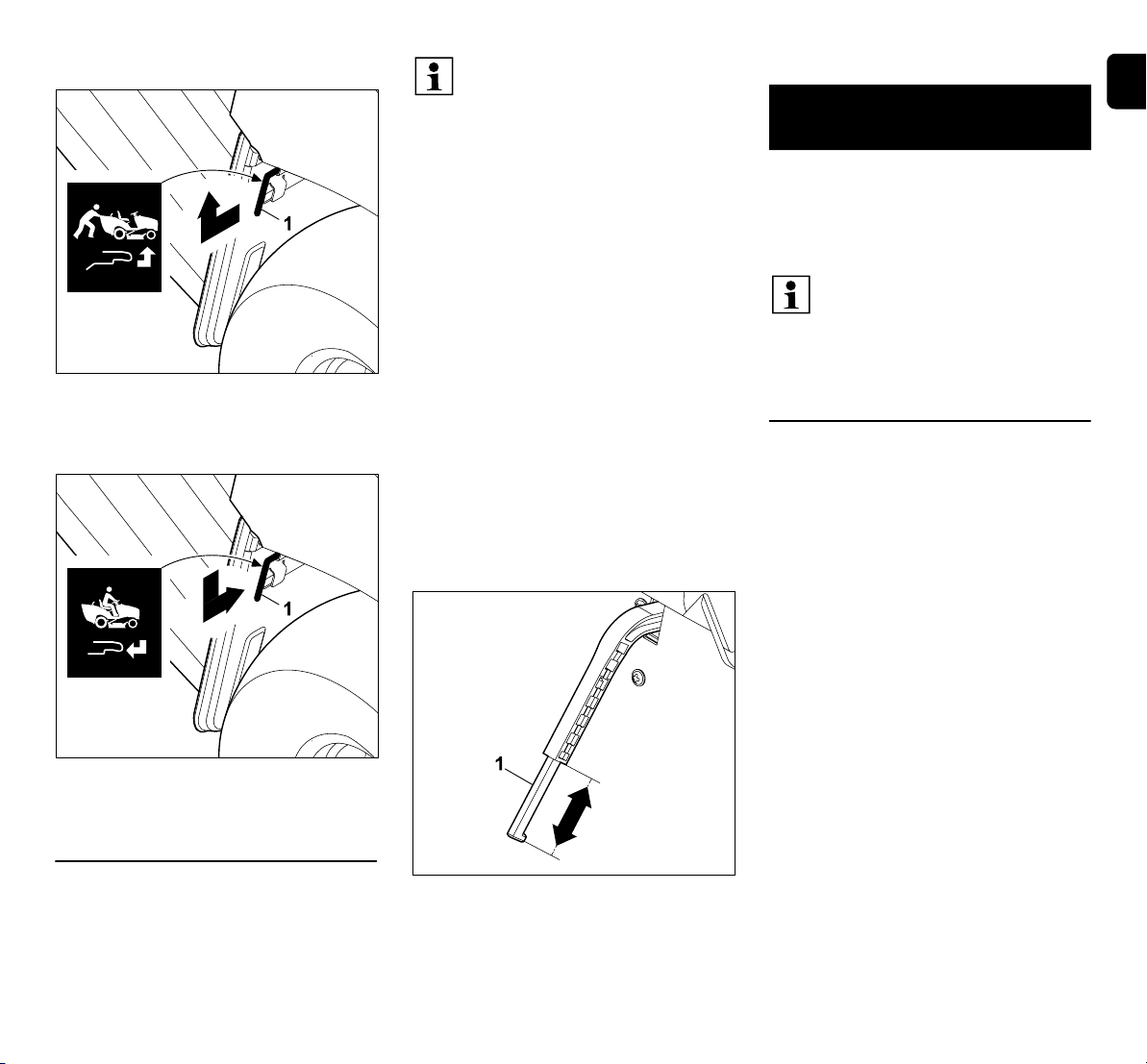
8.8 Reverse mowing safety switch
The reverse mowing safety switch
enables the mowing deck for
mowing in reverse driving
direction. The mowing deck is
automatically disengaged for safety
reasons if reverse mowing is not enabled.
For reverse mowing, briefly press reverse
mowing safety switch (1) once with the left
foot within a defined time window.
1 Enable with the mowing deck
disengaged:
● Bring the ride-on mower to a standstill
and select reverse driving direction.
(Ö 8.9)
● Briefly press the reverse mowing safety
switch once with the left foot.
● Engage the mowing deck and start
reverse mowing within 5 seconds.
(Ö 8.5), (Ö 8.6)
Reverse mowing can also be enabled
up to 1 second after starting.
2 Enable with the mowing deck
engaged:
● Briefly press the reverse mowing safety
switch once with the left foot during
mowing operation.
● Switch to reverse driving direction
within 5 seconds and continue mowing.
(Ö 8.9)
Reverse mowing can also be enabled
up to 1 second after changing the
driving direction.
If the reverse mowing safety switch
is continuously pressed, the switch
must be released within the time
window and pressed again.
The "reverse mowing" symbol
flashes on the display on the
models RT 6112 C, RT 6112 ZL
and RT 6127 ZL until reverse
mowing is enabled. (Ö 10.5)
22
0478 192 9809 A - EN

8.9 Driving direction selector lever
The driving direction is selected
using the driving direction
selector lever.
The ride-on mower drives in the
selected direction after the drive pedal is
actuated – actuating the driving direction
selector lever alone does not set the
machine in motion.
For safety reasons, the driving
direction selector lever is locked
when the drive pedal is pressed.
Therefore release the drive pedal
before actuating the driving
direction selector lever.
Selecting the driving direction:
8.10 Steering wheel
Warning:
Always hold the steering wheel
firmly in both hands when driving.
ENES
PTEL
Forward driving direction:
Move the driving direction selector
lever (1) to the front position.
Reverse driving direction:
Move the driving direction selector
lever (1) to the rear position.
0478 192 9809 A - EN
Turning the steering wheel (1) to the left L
or right R changes the driving direction of
the machine.
The further the steering wheel (1) is
turned, the smaller the turning radius.
8.11 Driver's seat adjustment
The driver's seat can be adjusted
to seven notched positions.
● Stop the engine. (Ö 13.3)
● Sit on the driver's seat and put your
right hand on the steering wheel.
1 With your left hand, lift and hold the
driver's seat adjustment lever (1).
2 Move the driver's seat (2) to the
required position. Then release the driver's
seat adjustment lever again and allow it to
engage.
8.12 Drive pedal
Note
Before actuating the drive pedal,
ensure that the correct driving
direction is selected at the driving
direction selector lever.
If the parking brake is engaged or
the brake pedal is pressed, the
drive pedal cannot be actuated.
The driving speed can be
continuously regulated via the
drive pedal.
23
Engaging the parking brake:
Stopping:
Take foot off the drive pedal (selfpropulsion) (1).
Reducing the driving speed:
Reduce pressure on the drive
pedal (1).
Increasing driving speed:
Press down drive pedal (1).
8.13 Brake pedal
The machine can be braked when driving
and can be blocked at a standstill via the
brake pedal.
Press the brake pedal (1).
The more firmly the brake pedal (1) is
pressed, the more the rear wheels are
braked.
Warning!
Never operate the machine with a
defective brake.
Always have a defective brake
repaired or adjusted by a specialist
dealer.
STIHL recommends STIHL
specialist dealers.
Never try to service the brakes
yourself.
8.14 Parking brake
The rear wheels of the machine
are blocked by the engaged
parking brake. This prevents the
ride-on mower from being set in motion
inadvertently (e.g. on slopes, etc.).
Note
Always check the function of the
brakes before engaging the parking
brake.
Press the brake pedal (1) down to the stop
with the foot and hold. Pull the parking
brake lever (2) upwards.
● Release the brake pedal again.
The parking brake is activated if the
brake pedal remains in the pressed
position.
The "parking brake engaged" symbol
appears on the display of the models
RT 6112 C, RT 6112 ZL and
RT 6127 ZL when the parking brake is
engaged. (Ö 10.5)
● Release the parking brake lever. This
swings downwards. The rear wheels
are blocked.
24
0478 192 9809 A - EN
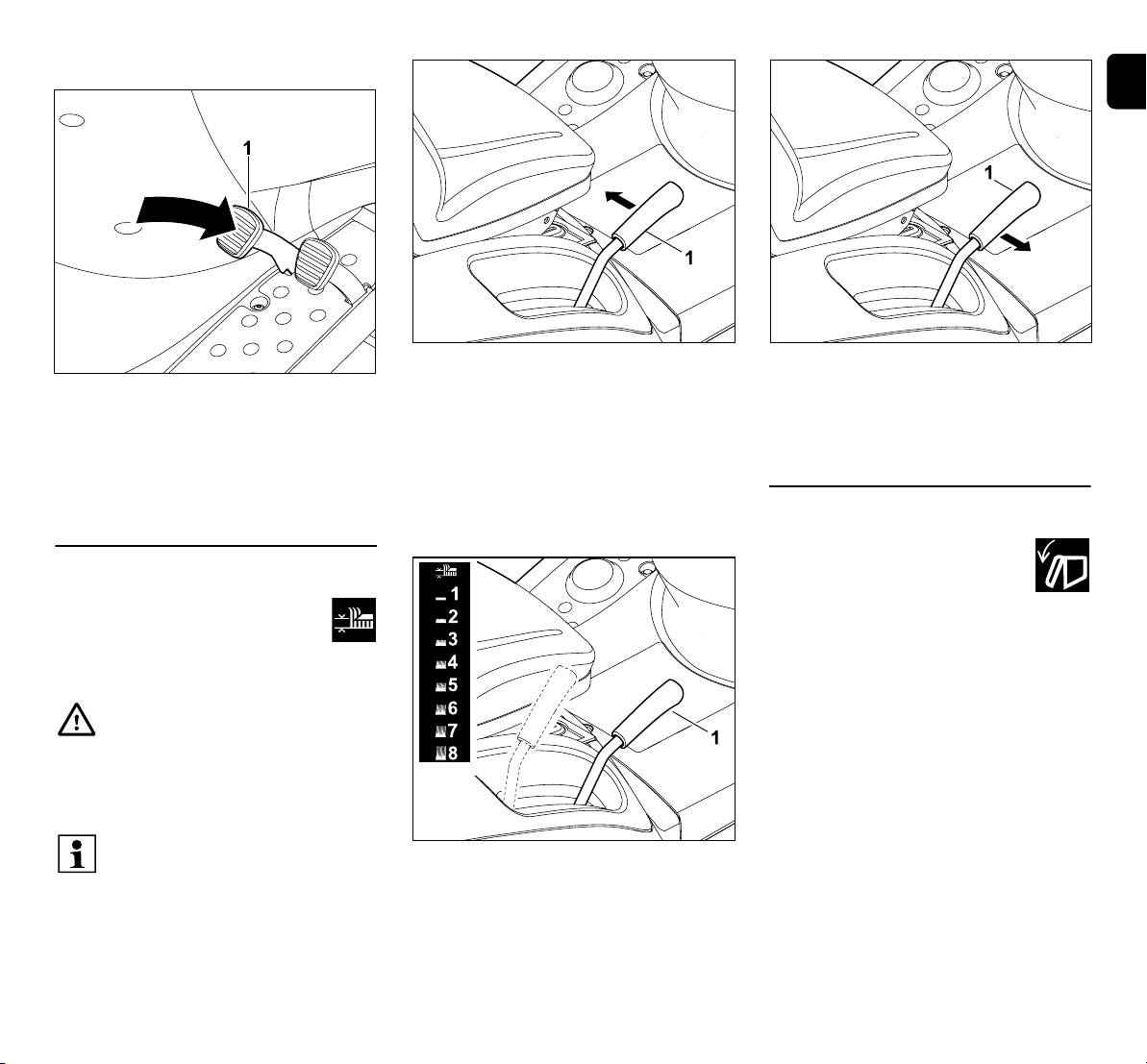
Releasing the parking brake:
ENES
PTEL
Briefly press on brake pedal (1) with the
foot.
● The brake pedal returns to the initial
(unactuated) position. The parking
brake is deactivated and the rear
wheels are no longer blocked.
8.15 Cutting height adjustment lever
Eight cutting levels can be set
using the cutting height adjustment
lever.
Raising and lowering the mowing deck:
Risk of injury!
Always hold the cutting height
adjustment lever when adjusting
the cutting height.
Adjust the cutting height only when
the ride-on mower is at a standstill.
The procedure for releasing the
cutting height adjustment lever
depends on whether the mowing
deck is installed or removed.
Releasing the cutting height adjustment
lever:
With the mowing deck installed Pull the
cutting height adjustment lever (1) inwards
(towards the driver's seat) and hold.
With the mowing deck removed Push
the cutting height adjustment lever (1)
slightly downwards and then inwards
(towards the driver's seat) and hold.
Guide the released cutting height
adjustment lever (1) upwards/downwards
and set the required cutting height.
Locking the cutting height adjustment
lever:
Guide the cutting height adjustment
lever (1) outwards until it engages in the
chosen notched position.
8.16 Grass catcher box emptying lever
The grass catcher box can be
emptied using the grass catcher
box emptying lever, without the
user having to leave the driver's
seat.
● Disengage the mowing deck.
(Ö 8.5), (Ö 8.6)
● Brake the machine to a complete
standstill.
● Keep the brake pedal pressed or
engage the parking brake.
0478 192 9809 A - EN
25
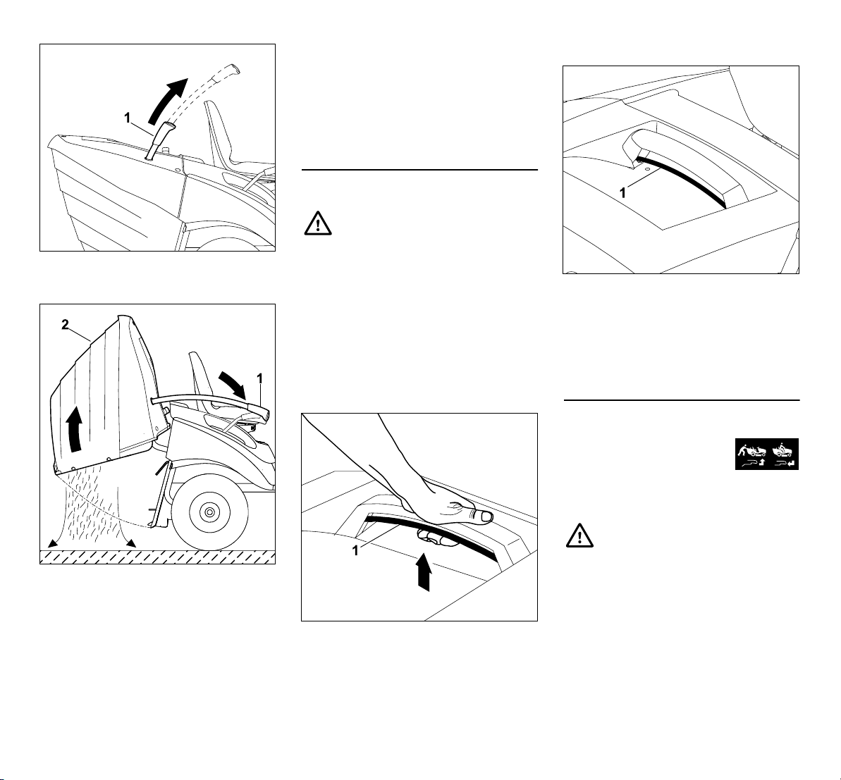
Pull the grass catcher box emptying
lever (1) upwards.
Push the grass catcher box emptying
lever (1) forwards. The grass catcher
box (2) swings upwards and the clippings
fall out.
The "grass catcher box open or missing"
symbol appears on the display of the
models RT 6112 C, RT 6112 ZL and
RT 6127 ZL when the grass catcher box is
raised. (Ö 10.5)
● Slowly move the grass catcher box
emptying lever towards the rear and
allow the grass catcher box to reengage with the rear panel.
● Press the grass catcher box emptying
lever downwards and move to the initial
position.
8.17 Grass catcher box release lever
Warning:
Ensure that you do not pinch your
fingers when actuating the grass
catcher box release lever.
The grass catcher box release lever is
located underneath the grass catcher box
handle.
The grass catcher box release lever must
be pulled upwards and held before
attaching or detaching the grass catcher
box.
Releasing the grass catcher box:
Pull grass catcher box release lever (1)
fully upwards and hold.
● The grass catcher box is released and
can be removed.
Locking the grass catcher box:
After attaching the grass catcher box,
release the pulled-out grass catcher box
release lever (1). Ensure that the lock
engages fully.
– Once locked, the grass catcher box is
firmly attached to the machine again.
8.18 Gearbox freewheel lever
The gearbox can be
disengaged (e.g. for pushing
the machine) or engaged (for
self-propulsion) using the gearbox
freewheel lever.
Warning!
Risk of crush injuries!
Only pull out the gearbox freewheel
lever on level surfaces, as the
machine may be set in motion.
If the machine is parked with the
gearbox disengaged, the parking
brake must be engaged.
26
0478 192 9809 A - EN
Disengaging the gearbox:
Pull the gearbox freewheel lever (1)
outwards to the stop and then raise.
Engaging the gearbox:
Guide the gearbox freewheel lever (1)
downwards and then press inwards to the
stop.
8.19 Level sensor (grass catcher box)
A continuous tone sounds if the grass
catcher box is full. This signals that the
grass catcher box needs to be emptied.
Disengaging the mowing deck
stops the continuous tone.
The time for the filled grass catcher box
signal is adjusted by modifying the length
of the (grass catcher box) level sensor.
This allows you to adapt filling of the grass
catcher box to the characteristics of the
clippings.
A shorter sensor generally causes later
triggering of the signal (the grass catcher
box is filled to a greater extent, ideal for
very dry clippings).
The level sensor can be adjusted to 6
notched positions.
In delivery condition, the level sensor
(grass catcher box) is fully extended.
Adjusting the level sensor:
● Stop the engine. (Ö 13.3)
● Engage the parking brake. (Ö 8.14)
● Remove the grass catcher box.
(Ö 13.10)
Extend or shorten the level sensor by
moving the slide (1) of the (grass catcher
box) level sensor in the direction of the
arrows.
● Attach the grass catcher box. (Ö 13.10)
9. Electronics
In order to ensure safe operation, the rideon mower is equipped with electronics
which check all the safety devices before
each starting procedure and when the
mower is running.
The electronics in the models
RT 6112 C, RT 6112 ZL,
RT 6127 ZL also control the
display. The display on these
models therefore shows additional
information.
9.1 Self-diagnosis when starting
Before the engine is started, the
electronics perform self-diagnosis. This
checks switches, wiring, etc. for correct
functioning.
Activating self-diagnosis:
● Sit on the driver's seat.
● Release the parking brake. (Ö 8.14)
● Turn the ignition key to the "ignition on"
position (Ö 8.1) – do not press any
buttons and switches or actuate any
pedals.
Self-diagnosis without faults:
A short beep sounds – the electronics are
activated and the ride-on mower is ready
to start.
RT 6112 C, RT 6112 ZL, RT 6127 ZL:
All symbols are shown on the display for
2 seconds. The operating hours can be
read off for 5 seconds.
● Start the engine. (Ö 13.2)
ENES
PTEL
0478 192 9809 A - EN
27
Self-diagnosis with faults:
A continuous beep or three successive
beeps sound.
A continuous beep signals a fault in the
electronics or a battery connected with the
incorrect polarity.
● Turn the ignition key to the "engine off"
position. (Ö 8.1)
● Check the polarity of the battery
connections and connect the wiring
correctly if necessary. (Ö 15.19)
● Repeat self-diagnosis.
If the continuous beep continues to
sound even after the battery is correctly
connected, an electronic fault is
present. Consult your specialist dealer;
STIHL recommends STIHL specialist
dealers.
Three successive beeps signal a fault in
the electrics (short circuit) or in the seat
switch. It is not possible to start the engine.
RT 6112 C, RT 6112 ZL, RT 6127 ZL:
The relevant symbols and the text ERROR
flash on the display.
● Turn the ignition key to the "engine off"
position. (Ö 8.1)
● Have a detailed diagnosis carried out
by a specialist dealer. STIHL
recommends STIHL specialist dealers.
9.2 Ride-on mower faults during
operation
The electronics monitor the safe condition
during operation. Three successive beeps
sound if there is a fault in the electrics
(short circuit, loose connectors, broken
wire).
The engine is stopped – the respective
symbol and the text "ERROR" flash on the
display on the models RT 6112 C,
RT 6112 ZL, RT 6127 ZL.
Behaviour:
● Turn the ignition key to the "engine off"
position. (Ö 8.1)
● Activate self-diagnosis. (Ö 9.1)
If the fault cannot be rectified,
detailed diagnosis is necessary.
Consult your specialist dealer;
STIHL recommends STIHL
specialist dealers.
9.3 Electronics faults
In rare cases, electronics faults may occur
during operation of the mower. A
continuous beep sounds and the engine is
stopped.
Behaviour:
● Turn the ignition key to the "engine off"
position. (Ö 8.1)
● Activate self-diagnosis. (Ö 9.1)
● Restart the engine. (Ö 13.2)
If the fault cannot be rectified,
detailed diagnosis is necessary.
Consult your specialist dealer;
STIHL recommends STIHL
specialist dealers.
10. Display on the RM 6112 C, RM 6112 ZL, RM 6127 ZL
Faults, operating information and active
functions are shown on the display.
The display is protected against
damage (e.g. due to water) on
account of its design. It may be
affected by fogging due to
temperature variations and high air
humidity. After the ride-on mower
has been started, ingressed
moisture dissipates within a few
minutes under the influence of heat
from the engine.
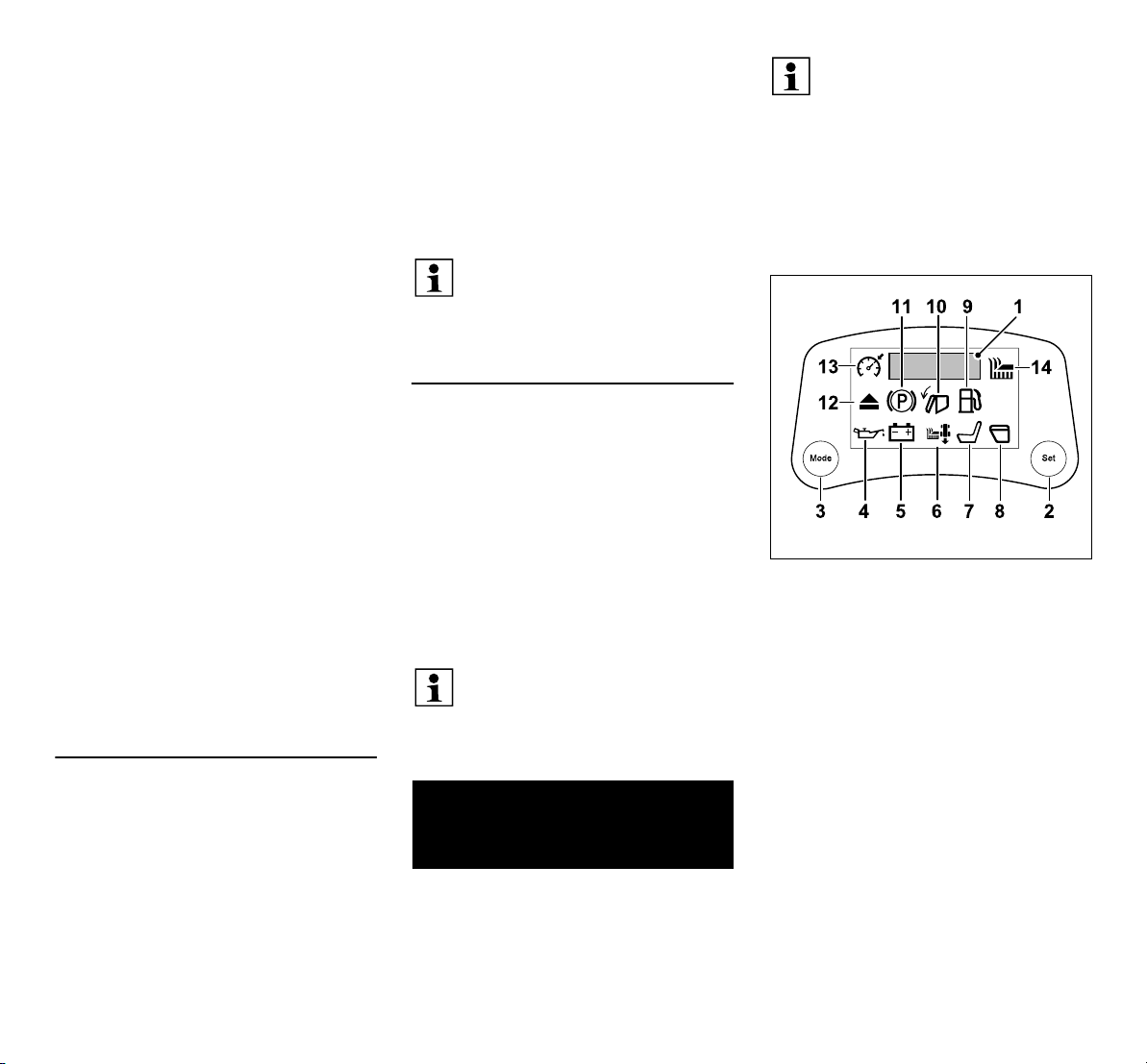
1 5-digit segmental display (Ö 10.1)
2 Set button (Ö 10.2)
3 Mode button (Ö 10.3)
Faults (Ö 10.4)
4 Engine oil pressure too low
(RT 6127 ZL)
5 Battery fault
Operating information (Ö 10.5)
6 Reverse mowing
7 Driver's seat unoccupied
8 Grass catcher box open or missing
9 Fuel reserve
10 Grass catcher box full
11 Parking brake engaged
28
0478 192 9809 A - EN

Operating information (Ö 10.5)
12 Discharge chute removed
Active functions (Ö 10.6)
13 Cruise control active
14 Mowing deck active
10.1 5-digit segmental display
The 5-digit segmental display provides
information about operating hours and
battery voltage. It also indicates faults by
displaying the text ERROR.
The operating hours and battery voltage
can be called up during operation by
pressing the Mode button. (Ö 10.3)
Operating hours:
Display of the engine operating hours in
full hours (e.g. 281 h).
The hour meter cannot be reset.
The correct times for maintenance or
service operations are determined based
on the meter. These are indicated in the
maintenance schedule. (Ö 15.1)
Battery voltage:
Display of the current battery voltage in
volts (e.g. 12.0 V).
10.2 Set button
Pressing the Set button during
display of the operating hours or
battery voltage switches to
continuous display.
Turning the ignition key to the "engine off"
position resets the display to the default
setting (display of operating hours or
battery voltage for 5 seconds).
10.3 Mode button
Pressing the Mode button switches
between the individual displays:
1 Operating hours [h]
2 Battery voltage [V]
3 No display
The operating hours and battery voltage
are both displayed for 5 seconds. Press
the Set button for a continuous display.
(Ö 10.2)
10.4 Display of faults
Engine oil pressure too low
symbol:
The oil pressure required for
correct operation of the engine is too low.
The engine will be stopped within 3
seconds.
Avoid damage to the machine.
The oil pressure warning is not an
oil level indicator. Therefore check
the oil level at regular intervals.
● Do not attempt to restart the engine.
● Visually check for oil leaking from the
engine.
● Check the oil level and top up the
engine oil if necessary.
Battery fault symbol:
The battery voltage is too low. The
battery is faulty or is not
recharging. The current voltage is
additionally shown in volts on the display
(e.g. 10.5 V).
The engine is stopped or cannot be
started.
● Do not attempt to restart the engine.
● Check the battery voltage on the
display.
● Check the fuses and replace if
necessary. (Ö 15.20)
● Visually check for leaking battery fluid.
● Check battery terminals for corrosion
and correct seating.
● Charge the battery. (Ö 15.21)
● Replace the faulty battery. (Ö 15.19)
10.5 Display of operating information
If symbols do not display as
expected or do not disappear as
described, the probable cause is a
fault in the respective switch, in the
plug connections or in the wiring.
Consult your specialist dealer.
STIHL recommends STIHL
specialist dealers.
Reverse mowing symbol:
The symbol is continuously
displayed when reverse mowing is
enabled.
The symbol flashes when the reverse
mowing safety switch is pressed or if an
enable is required for reverse mowing.
(Ö 8.8)
The symbol disappears from the
display:
– When reverse mowing is completed.
Switches from flashing to continuous
display:
– When reverse mowing is enabled.
– When the mowing deck is manually
disengaged within the time window.
ENES
PTEL
0478 192 9809 A - EN
29

– When the mowing deck is automatically
disengaged if reverse mowing is not
enabled.
Driver's seat unoccupied
symbol:
The driver's seat is unoccupied.
The seat switch is one of the ride-on
mower's safety devices (Ö 12.).
If the "driver's seat unoccupied" symbol
appears on the display, the engine cannot
be started without the parking brake
engaged and the mowing deck cannot be
engaged.
The symbol disappears from the
display:
– When the user sits on the driver's seat.
Grass catcher box open or
missing symbol:
The grass catcher box is open or
the grass catcher box or deflector
(accessory) are not installed or not
correctly engaged. The symbol is also
displayed when emptying the grass
catcher box. (Ö 13.9)
If the grass catcher box is raised (e.g. for
emptying) while the mowing deck is
engaged, the engine is stopped for safety
reasons.
The symbol disappears from the
display:
– When the grass catcher box is closed.
(Ö 13.9)
– When the grass catcher box or deflector
(accessory) are correctly installed.
(Ö 13.10)
The fuel is down to the reserve level, there
is still approx. 2 litres of fuel in the tank.
(Ö 13.1)
The symbol disappears from the
display:
– When the fuel is topped up.
Grass catcher box full symbol:
The grass catcher box is full, a
continuous tone sounds. (Ö 8.19)
The continuous tone stops after the
mowing deck is disengaged. (Ö 8.5)
The symbol disappears from the
display:
– When the grass catcher box is emptied.
Parking brake engaged symbol:
The parking brake is engaged.
(Ö 8.14)
The symbol disappears from the
display:
– When the parking brake is released.
Discharge chute removed
symbol:
The discharge chute has been
removed. (Ö 15.5)
The engine cannot be started for safety
reasons.
The symbol disappears from the
display:
– When the discharge chute is correctly
installed. (Ö 15.6)
10.6 Display of active functions
If symbols do not display as
expected or do not disappear as
described, the probable cause is a
fault in the respective switch, in the
plug connections or in the wiring.
Consult your specialist dealer.
STIHL recommends STIHL
specialist dealers.
Cruise control active symbol:
Cruise control has been activated.
(Ö 8.7)
The display disappears when cruise
control is switched off.
Mowing deck active symbol:
The mowing deck is engaged.
(Ö 8.6)
The display disappears when the
mowing deck is disengaged.
11. Notes on working with the machine
Warning:
Risk of injury.
Before each use, observe all
information regarding safe
operation of the machine.
Working on slopes requires special
concentration and care.
Fuel reserve symbol:
30
0478 192 9809 A - EN

Note
Check the mowing deck for correct
installation position before starting
work.
Select a flat, even area for initial
use of your machine and mow in
straight and slightly overlapping
strips for practising purposes.
Grass should always be mowed
when dry.
A perfect, thick lawn is achieved by
– Mowing at high speed (throttle lever in
MAX position) and a slow driving
speed.
– Regular mowing and keeping the grass
short.
– Not cutting the lawn too short in hot, dry
conditions as it will be burnt by the sun
and become unsightly.
– Using sharp mowing blades. Mowing
blades should therefore be regularly
sharpened or replaced.
– Changing the cutting direction.
Mowing tall grass
If the grass is very high, it is better to mow
it in two stages:
– use the highest cutting height,
maximum engine speed and slow
driving speed for the first mowing
operation;
– for the second mowing operation, select
the desired cutting height and set the
maximum engine speed. Adjust the
driving speed to the condition of the
lawn.
Warning – fire hazard!
Avoid overloading the mowing deck
drive. Overloading may lead to
constant slipping of the V-belt and
consequently to a fire hazard due to
overheating.
Unusual running noise, e.g. a
"squealing" (slipping noise) of the
V-belt, indicates overloading. For
this reason, never mow in high
grass when the discharge chute is
blocked or the grass catcher box is
full; use a mulching kit (special
accessory) if necessary.
The mowing deck, particularly the
V-belt area, must always be kept
free of combustible material (grass,
leaves, etc.). It should also be
cleaned regularly to prevent a fire
hazard.
Preventing blockage of the discharge
chute
If the discharge chute becomes blocked
with grass, reduce the driving speed. This
may be too high in relation to the lawn
conditions. Pull out the slide of the level
sensor fully. (Ö 8.19)
If the problem persists, the probable cause
is damaged or worn wings on the mowing
blades. Replace the mowing blades.
(Ö 15.13)
Clean the mowing deck, discharge chute
and mowing blades after each use to
prevent the accumulation of grass
deposits. (Ö 15.2)
Fertilisation
Mowing the grass deprives the ground of
permanent nutrients, which can be
returned by using a high-grade, long-term
lawn fertiliser. Usually, fertilising three
times per mowing season is necessary.
For this purpose, the lawn should be dry,
so that the fertiliser does not stick to the
grass blades and burns them. It is then
better to water the lawn, which results in
the fertiliser being flushed off the grass
blades. (Observe manufacturer's
instructions for use.)
Natural fertilising is possible using lawn
clippings. This is made possible by the use
of the mulching kit. The mulching kit is
available as a special accessory and is not
included in the standard equipment.
(Further information is available from your
STIHL specialist dealer.)
Ground-conserving working
The most important factors for groundconserving working are operating
technique and ground moisture.
In order to achieve clean mowing results,
the driving speed must be adapted to the
condition of the grass to be mowed (height
and density) and to the moisture of the
lawn.
Executing curves that are too tight
increases the loading on the turf and leads
to poor mowing results, particularly on wet
grass, as the wheels sink into the soft
grass.
12. Safety devices
The machine is equipped with several
safety devices for safe operation and for
the prevention of improper use.
Risk of injury!
If a safety device is found to be
defective, the machine must not be
operated. Consult a specialist
dealer; STIHL recommends STIHL
specialist dealers.
ENES
PTEL
0478 192 9809 A - EN
31

To start the engine, the following
conditions must always be fulfilled:
– The discharge chute must be correctly
installed.
– The brake pedal must be pressed or the
parking brake engaged.
The engine is switched off if the user:
– Leaves the driver's seat with the
mowing deck engaged.
– Lifts the grass catcher box or removes
the deflector (special accessory) with
the mowing deck engaged.
– Removes the discharge chute with the
mowing deck disengaged.
– Leaves the driver's seat without
engaging the parking brake.
Integrated blade run-down brake:
RT 5097, RT 5097 C, RT 5097 Z,
RT 5112 Z, RT 6112 C, RT 6112 ZL:
Following disengagement, the mowing
blades come to a standstill after 5
seconds at the latest.
RT 6127 ZL:
Following disengagement, the mowing
blades come to a standstill after 7
seconds at the latest.
Following engagement of the
mowing deck, the mowing blades
turn and a wind noise is audible.
The run-on time corresponds to the
duration of the wind noise following
disengagement. This can be
measured using a stopwatch.
13. Operating the machine
Risk of injury!
Carefully read and observe the
entire section "For your safety"
before operating the machine.
(Ö 4.)
For safety reasons, the machine
must not be used on slopes with an
inclination of more than 10°
(17.6%).
A slope inclination of 17.6%
corresponds to a vertical height
increase of 17.6 cm for a 100 cm
horizontal distance.
● Familiarise yourself with the controls on
the machine before using it. (Ö 8.)
● Before operating the machine, inspect
the maintenance schedule and carry
out all relevant maintenance
operations. (Ö 15.1)
● Check the safety devices before each
use. (Ö 12.)
The ride-on mower must not be
operated if safety devices are missing
or damaged or have been bypassed or
modified.
13.1 Filling the fuel tank
Maximum tank capacity:
9litres
Recommendation:
Fresh good quality fuel, please
refer to the engine instruction manual for
information on fuel grade (octane rating).
– Unleaded petrol.
Filling procedure:
● Stop the engine and allow it to cool
down (warm to the touch). (Ö 13.3)
● Engage the parking brake. (Ö 8.14)
To prevent fuel spillage, use a
suitable funnel (not included in
standard equipment) when filling
up.
Pour in the fuel slowly and carefully. In
order to prevent the fuel from overflowing,
filling should be performed in several
stages.
Remove the funnel between the individual
filling operations in order to visually check
the filling level in the tank.
The more fuel has already been filled into
the tank, the smaller the filling quantities
should be for each filling operation. To give
the fuel room to expand, never fill the fuel
tank past the lower edge of the filler neck.
Tank cap:
Unscrew the tank cap (1) (note direction of
arrow) and remove.
● Fill the fuel into the tank using a suitable
funnel (not included in standard
equipment) (see Filling procedure).
32
0478 192 9809 A - EN

Fit and screw on the tank cap (1) (note
direction of arrow). Then tighten the tank
cap (1) hand-tight.
● Wipe away any spilled fuel and allow it
to evaporate before starting the engine.
13.2 Starting the engine
Avoid damage to the machine.
If the engine does not start
immediately, leave breaks between
the starting attempts.
Never leave the ignition key in the
"start engine" position for more than
10 seconds.
The discharge chute must be
correctly installed to start the
engine. (Ö 15.6)
Before starting:
● Check the engine oil level. (Ö 15.8)
● Remove grass residues from the
mowing deck and engine compartment.
● Check the fuel and top up if
necessary. (Ö 13.1)
● Before each use, check the braking
function. (Ö 13.5)
● Perform all personal settings (driver's
seat adjustment) on the machine – not
when the engine is running!
● Never start the machine in the vicinity of
other persons, particularly children, or
animals.
Starting sequence:
● Open the fuel cock. (Ö 15.7)
● Sit on the driver's seat.
● Before starting, press the brake pedal
to the stop and hold or engage the
parking brake. (Ö 8.13), (Ö 8.14)
● Insert the ignition key in the ignition lock
and turn to the "ignition on" position.
(Ö 8.1)
● Cold engine:
RT 5097, RT 5097 C, RT 6112 C:
Set the throttle lever to the choke
position. (Ö 8.2)
RT 5097 Z, RT 5112 Z, RT 6112 ZL,
RT 6127 ZL:
Set the throttle lever to the MAX
position and pull the choke knob.
(Ö 8.3), (Ö 8.4)
Warm engine:
Set the throttle lever to the MAX
position. (Ö 8.2), (Ö 8.3)
● Turn the ignition key to the "start
engine" position.
The engine starts. As soon as the
engine is running, release the ignition
key. This returns automatically to the
"engine running" position.
● RT 5097, RT 5097 C, RT 6112 C:
Return the throttle lever to the MAX
position when the engine is running.
Note detent! (Ö 8.2)
RT 5097 Z, RT 5112 Z, RT 6112 ZL,
RT 6127 ZL:
Press in the choke knob. (Ö 8.4)
● When the engine is running, the foot
can be removed from the brake pedal or
the parking brake released.
13.3 Stopping the engine
● Brake the machine to a complete
standstill.
● Disengage the mowing deck.
(Ö 8.5), (Ö 8.6)
● Set the throttle lever to the MIN
position. (Ö 8.2), (Ö 8.3)
● Turn the ignition key to the "engine off"
position. The engine is stopped.
● Engage the parking brake. (Ö 8.14)
● Close the fuel cock if necessary.
(Ö 15.7)
● Remove the ignition key and store
safely.
13.4 Driving
Warning!
A low driving speed must always be
selected on rough terrain.
Before each change of direction,
especially on slopes, reduce the
driving speed appropriately.
Avoid damage to the machine!
In order to ensure optimum cooling
of the gearbox, always drive at the
maximum engine speed. Therefore
only regulate the driving speed
using the drive pedal and not the
throttle lever.
Before driving:
● Engage the gearbox freewheel
lever. (Ö 8.18)
ENES
PTEL
0478 192 9809 A - EN
33

● RT 5112 Z, RT 6112 C, RT 6112 ZL,
RT 6127 ZL:
With the mowing deck removed, press
the V-belt tensioner lever forwards and
lock in place. (Ö 14.1)
● Start the engine. (Ö 13.2)
Forward driving:
● Select the forward driving
direction. (Ö 8.9)
● Disengage the parking brake, if
engaged. (Ö 8.14)
● Actuate the drive pedal – the machine
moves forwards. (Ö 8.12)
Reversing:
● Select the reverse driving
direction. (Ö 8.9)
● Disengage the parking brake, if
engaged. (Ö 8.14)
● Actuate the drive pedal – the machine
moves backwards. (Ö 8.12)
Forward driving with cruise control
(RT 6112 ZL, RT 6127 ZL):
● With the mowing deck removed, press
the V-belt tensioner lever forwards and
lock in place. (Ö 14.1)
● Start the engine. (Ö 13.2)
● Set the throttle lever to the MAX
position. (Ö 8.3)
● Set driving direction selector lever to
front position (forward driving direction).
(Ö 8.9)
● Disengage the parking brake, if
engaged. (Ö 8.14)
● By pressing the drive pedal, the driving
speed is regulated and the machine
moves forwards.
● Activating cruise control:
Maintain the required driving speed and
press the cruise control button for 1
second. (Ö 8.7)
Cruise control is activated when the
"cruise control active" symbol appears
on the display and the drive pedal is
locked in place.
When cruise control is activated, it is
possible to increase the set driving
speed by pressing on the drive pedal.
● The foot can be removed from the drive
pedal.
● Deactivating cruise control:
Press the brake pedal or cruise control
button. (Ö 8.7)
Cruise control is deactivated when the
"cruise control active" symbol
disappears from the display.
13.5 Braking
● Reduce the driving speed by easing the
pressure on the drive pedal – avoid
braking abruptly at the maximum
driving speed. (Ö 8.12)
● Press the brake pedal down evenly until
the machine comes to a
standstill. (Ö 8.13)
13.6 Adjusting the cutting height
Risk of injury!
Adjust the cutting height only when
the ride-on mower is at a standstill.
● Brake the machine to a complete
standstill.
● Release the cutting height adjustment
lever and set the required cutting
height. (Ö 8.15)
Level 1 Lowest cutting height
Level 8 Highest cutting height
RT 5112 Z, RT 6112 C,
RT 6112 ZL, RT 6127 ZL:
STIHL recommends mounting the
two gauge wheels in a lower bore.
In the lowest position, the gauge
wheels increase the distance
between the mowing deck and the
ground, ensuring an optimum
supply of air. The result is a more
attractive cutting pattern and better
collecting performance.
13.7 Mowing
If the mowing deck is engaged
when driving, the engine speed is
briefly reduced due to the additional
load (mowing blades starting to
rotate).
Before mowing:
● Read and observe the section "Notes
on working with the machine". (Ö 11.)
● Always set the maximum engine speed
during mowing. The mowing blade is
optimised for this speed – it produces
the best cutting pattern as well as the
most powerful suction effect for
collection of the clippings.
Engage the mowing deck in the
following sequence:
● Start the engine. (Ö 13.2)
● Set the throttle lever to the MAX
position. (Ö 8.2), (Ö 8.3)
34
0478 192 9809 A - EN

● Drive the ride-on mower onto the lawn.
Do not engage the mowing deck in tall
grass or when set to the lowest cutting
level. Only engage the mowing deck
when the machine is already on the
area to be worked.
● Forwards mowing:
Select the forward driving direction
(Ö 8.9), then engage the mowing deck
by pressing the mowing deck switch or
mowing deck button. (Ö 8.5), (Ö 8.6)
Reverse mowing:
Select the reverse driving direction
(Ö 8.9) and briefly press the reverse
mowing safety switch (Ö 8.8) once,
then engage the mowing deck by
pressing the mowing deck switch or
mowing deck button within 6 seconds.
(Ö 8.5), (Ö 8.6)
During mowing:
● Set the throttle lever to the MAX
position. (Ö 8.2), (Ö 8.3)
● Always adapt the driving speed to the
grass height/cutting level.
A low driving speed should be selected
when mowing tall grass/at a low cutting
level.
A permanent continuous tone
signals that the grass catcher box is
full. (Ö 13.9)
Changing the driving direction with the
mowing deck engaged:
● For reverse mowing, briefly press the
reverse mowing safety switch once
within the designated time window
(5 seconds/1 second after switching).
(Ö 8.8)
● Bring the machine to a standstill on the
lawn and set the required driving
direction using the driving direction
selector lever. (Ö 8.9)
● Continue mowing.
Disengage the mowing deck in the
following sequence:
● Drive onto an area of grass which has
already been mown or select the
highest cutting level. (Ö 8.15)
● Disengage the mowing deck by
pressing the mowing deck switch or
mowing deck button. (Ö 8.5), (Ö 8.6)
Risk of injury!
After disengaging the mowing deck,
beware of the mowing blade
running on for up to 7 seconds
before coming to a standstill.
(Ö 12.)
13.8 Programming automatic
disengagement of the mowing deck
The electromagnetic blade clutch
can be programmed so that the
mowing deck is automatically
disengaged when the grass catcher box is
full. This enhances operating convenience
as blockage of the discharge chute is
prevented.
● Stop the engine. (Ö 13.3)
● Turn the ignition key to the "ignition on"
position. (Ö 8.1)
● Wait for the electronics self-diagnosis –
do not press any buttons.
Activating automatic disengagement:
● Press the reverse mowing safety switch
and actuate the drive pedal at the same
time for 5 seconds.
A short beep signals that automatic
operation is switched on.
● The current setting is permanently
saved.
Deactivating automatic
disengagement:
● Set the driving direction selector lever
to forwards.
● Press the reverse mowing safety switch
and actuate the drive pedal at the same
time for 5 seconds.
Three beeps in quick succession signal
that automatic operation is switched off.
● The current setting is permanently
saved.
Programming automatic
disengagement using the Mode button
(only with RT 6112 C, RT 6112 ZL,
RT 6127 ZL):
● Set the driving direction selector lever
to forwards.
● Keep the mowing deck button pressed
and press the Mode button at the same
time – automatic disengagement is
switched on or off using the Mode
button (ON or OFF appears on the
display).
● The current setting is permanently
saved.
Checking the programming (only with
RT 6112 C, RT 6112 ZL, RT 6127 ZL):
● Press and hold the mowing deck
button. The mowing deck active symbol
and the text ON or OFF appear on the
display.
ON – The mowing deck is automatically
disengaged when the grass catcher box
is full.
OFF – The mowing deck is not
automatically disengaged when the
grass catcher box is full.
ENES
PTEL
0478 192 9809 A - EN
35

13.9 Emptying the grass catcher box
Risk of injury!
Only empty the grass catcher box
on level surfaces, as the centre of
gravity is changed by swinging up
the grass catcher box and thus the
danger of tipping over is increased.
A permanent continuous tone
during mowing signals that the
grass catcher box is completely full
and must be emptied.
The continuous tone ceases once
the mowing deck has been
disengaged.
The "grass catcher box full" symbol
appears on the display of the
models RT 6112 C, RT 6112 ZL
and RT 6127 ZL when the grass
catcher box is full. (Ö 10.5)
The following points must be noted if
the grass catcher box is not being
completely filled:
● Correctly adjust the level sensor (grass
catcher box). (Ö 8.19)
● When emptying the grass catcher box,
check the discharge chute for blockage
and clean if necessary.
● Check the wings of the mowing blades
for damage or wear and replace if
necessary. (Ö 15.13)
Emptying the grass catcher box:
● Disengage the mowing deck.
(Ö 8.5), (Ö 8.6)
The continuous tone ceases.
● Select the highest cutting level.
(Ö 8.15)
● Drive the machine to the point at which
the clippings are to be emptied.
● Pull out the grass catcher box emptying
lever and push it forwards. (Ö 8.16)
The grass catcher box swings upwards
and the clippings fall out.
● If necessary, drive forwards slightly with
the grass catcher box raised.
● Briefly swing the grass catcher box up
and down so that all the clippings fall
out.
● Slowly move the grass catcher box
emptying lever towards the rear and
allow the grass catcher box to reengage with the rear panel.
● Release the grass catcher box
emptying lever again and press down
until it has returned to the initial
retracted position.
13.10 Removing and attaching the
grass catcher box
The following points must be noted
before removing:
● Disengage the mowing deck.
(Ö 8.5), (Ö 8.6)
● Empty the grass catcher box. (Ö 13.9)
● Engage the parking brake. (Ö 8.14)
● Stop the engine. (Ö 13.3)
When removing and attaching the
grass catcher box, the grass
catcher box release lever must
always be held in the released
position until the grass catcher box
has been fully removed or attached.
Removing the grass catcher box:
Pull the grass catcher box release lever (1)
upwards and hold.
Remove the grass catcher box (1).
36
0478 192 9809 A - EN

Attaching the grass catcher box:
ENES
PTEL
Position the grass catcher box (1) on both
snap-in hooks (2) on the rear panel.
● Actuate and hold the grass catcher box
release lever. (Ö 8.17)
Raise the grass catcher box (1) to the
stop.
● Release the grass catcher box release
lever and ensure that the grass catcher
box engages. (Ö 8.17)
If the machine is operated without
the grass catcher box or deflector
(accessory), the mowing deck
cannot be engaged and
the engine stops automatically.
13.11 Pulling loads
Risk of injury!
The driving characteristics of the
machine change when transporting
loads (e.g. longer braking
distance). The heavier the load, the
more the driving characteristics are
changed. Therefore select a lower
driving speed when pulling loads.
Avoid damage to the machine.
The maximum pulled load is
decreased on inclines.
● Before attaching loads, check the
braking function. (Ö 13.5)
Maximum trailer weight on a level surface
= 250 kg
Maximum trailer weight on a maximum 10°
inclination = 100 kg
Maximum coupling load = 40 kg
Maximum pulled load = 40 kg
A pulled load of 40 kg at the trailer
coupling is achieved when pulling a
trailer with a weight of 250 kg on a
level surface.
13.12 Operating on slopes
● Check the braking function before
operating the mower on slopes.
(Ö 13.5)
0478 192 9809 A - EN
37

● Drive slopes in a longitudinal direction.
Driving transversely increases the
danger of tipping over – note the
maximum slope inclination. (Ö 4.7)
● Avoid changes of direction on slopes –
if changes of direction cannot be
avoided, they must be executed with
particular care.
14. Mowing deck
14.1 Removing the mowing deck
Detaching the V-belt cover:
Slackening the V-belt (RT 5097,
RT 5097 C, RT 5097 Z):
Risk of injury!
Prior to all operations on the
mowing deck, carefully read and
observe the section "For your
safety". (Ö 4.)
Danger of pinching when
removing the mowing deck due to
its inherent weight. Therefore
ensure that no body parts (hands,
fingers, feet, etc.) are positioned
directly under the mowing deck.
● Park the machine on level and solid
ground.
● Turn the front wheels to the left or right
to the stop.
● Stop the engine. (Ö 13.3)
● Remove the ignition key.
● Engage the parking brake. (Ö 8.14)
● Select the lowest cutting level. (Ö 13.6)
● Remove the grass catcher box.
(Ö 13.10)
● Remove the discharge chute. (Ö 15.5)
Loosen the screw (1) behind the right front
wheel until it turns freely.
Press the retaining plate (1) forwards and
hold in place. Fold the V-belt cover (2)
downwards.
Pull the tension spring (1) forwards,
detach and set down.
Slackening the V-belt (RT 5112 Z,
RT 6112 C, RT 6112 ZL, RT 6127 ZL):
Detach the retainer (1) from the V-belt
tensioner lever.
38
0478 192 9809 A - EN

Press the V-belt tensioner lever (1)
forwards and hold in place. Engage the
retainer (2) at the frame as shown. Make
sure that the V-belt tensioner lever is fixed
in the front position.
Detaching the mowing deck at the rear:
Risk of injury!
The cutting height adjustment lever
is under tension when the mowing
deck is detached at the rear.
Therefore carefully set the highest
cutting level immediately after
detaching the mowing deck.
Pull out the cotter pin (1) upwards.
Lift up the mowing deck slightly and hold.
Push the mounting (2) outwards and
remove the retaining pin (3) from the
mounting.
● Repeat this procedure on the other
side.
● Carefully and slowly set down the
mowing deck.
Detaching the V-belt:
Press the retaining plate (1) forwards and
hold in place. Pull the V-belt (2) forwards
and detach.
Releasing the V-belt from the tension
roller (RT 5112 Z, RT 6112 C,
RT 6112 ZL, RT 6127 ZL):
Push the locking pin (1) approx. 0,5 cm
upwards and hold. Detach the V-belt (2)
from the tension roller (3).
After the V-belt is detached, push
the locking pin down again as far as
it will go until it engages in the
cover. After engagement, check
that the locking pin is securely
seated.
Detaching the mowing deck at the front
(RT 5097, RT 5097 C, RT 5097 Z):
ENES
PTEL
0478 192 9809 A - EN
39

Remove the cotter pin (1). Lift the mowing
deck slightly and detach it from the front
mowing deck mounting (2). Carefully
release the mowing deck.
● Repeat this procedure on the other
side.
● Carefully and slowly set down the
mowing deck.
Detaching the mowing deck at the front
(RT 5112 Z, RT 6112 C, RT 6112 ZL,
RT 6127 ZL):
Push the mowing deck (1) forwards and
detach it at the front mowing deck
mounting (2). The mounting automatically
swings upwards.
● Carefully and slowly set down the
mowing deck.
Removing the mowing deck:
● Set the highest cutting level.
Pull the mowing deck (1) out from under
the ride-on mower either to the left or right.
14.2 Installing the mowing deck
Risk of injury!
Prior to all operations on the
mowing deck, carefully read and
observe the section "For your
safety". (Ö 4.)
Danger of pinching when
installing the mowing deck due to
its inherent weight. Therefore
ensure that no body parts (hands,
fingers, feet, etc.) are positioned
directly under the mowing deck.
● Park the machine on level and solid
ground.
● Turn the front wheels to the left or right
to the stop.
● Stop the engine. (Ö 13.3)
● Remove the ignition key.
● Engage the parking brake. (Ö 8.14)
● Select the highest cutting level.
(Ö 13.6)
● Remove the grass catcher box.
(Ö 13.10)
● Remove the discharge chute. (Ö 15.5)
Pushing in the mowing deck:
● Position the V-belt in the opening in the
V-belt cover so that it is accessible and
can be attached.
Push the mowing deck (1) under the rideon mower either from the left or right.
● Select the lowest cutting level.
Risk of injury!
In the lowest cutting level, the
cutting height adjustment lever is
under tension. Do not touch the
cutting height adjustment lever
during installation of the mowing
deck.
40
0478 192 9809 A - EN

Attaching the mowing deck at the front
(RT 5097, RT 5097 C, RT 5097 Z):
Pull the front mowing deck mounting (1)
downwards and hold. Raise the mowing
deck slightly with one hand and insert the
mounting pin on the mowing deck into the
bore on the front mowing deck
mounting (1). Insert the cotter pin (2)
through the bore in the mounting pin.
● Repeat this procedure on the other
side.
Attaching the mowing deck at the front
(RT 5112 Z, RT 6112 C, RT 6112 ZL,
RT 6127 ZL):
Swivel the front mowing deck mounting (1)
downwards and attach to the mowing
deck (2) as shown. Push the mowing
deck (2) slightly to the rear, attaching the
front mowing deck mounting (1) to the
mowing deck.
Fitting the V-belt onto the tension roller
RT 5112 Z, RT 6112 C, RT 6112 ZL,
RT 6127 ZL:
Press the cover (1) downwards and hold it.
Push the locking pin (2) approx. 0,5 cm
upwards. Fit the V-belt (3) onto the tension
roller (4).
Push the locking pin (1) down again as far
as it will go. The locking pin (1) must
engage in the cover (2).
Check that the locking pin is seated
securely.
RT 5097, RT 5097 C, RT 5097 Z,
RT 5112 Z, RT 6112 C, RT 6112 ZL,
RT 6127 ZL:
Press the retaining plate (1) forwards and
hold in place. Pull the V-belt (2) forwards
and lift with the V-belt cover.
Fit the V-belt (2) correctly onto the V-belt
pulley (without twisting).
Attaching the mowing deck at the rear:
Before attaching, check that the
mowing deck is correctly attached
at the front mowing deck mounting.
● Raise the mowing deck with one hand
and hold. The bores in the mounting
must be aligned with the retaining pins
on the mowing deck.
ENES
PTEL
0478 192 9809 A - EN
41

Guide the retaining pins (1) into the bores
in the mounting (2). Insert the cotter pin (3)
into the retaining pin bores from above and
allow to engage.
● Repeat this procedure on the other
side.
Tensioning the V-belt (RT 5097,
RT 5097 C, RT 5097 Z):
Tensioning the V-belt (RT 5112 Z,
RT 6112 C, RT 6112 ZL, RT 6127 ZL):
Press the V-belt tensioner lever (1)
forwards and hold in place. Detach the
retainer (2).
Installing the V-belt cover:
Press the retaining plate (1) forwards and
hold in place. Fold the V-belt cover (2)
upwards. Guide the retaining plate (1) to
the rear and engage at the two retaining
tabs (3) on the V-belt cover.
Pull the tension spring (1) forwards and
attach to the mowing deck as shown.
42
Tension the V-belt by relieving the load on
the V-belt tensioner lever (1). Attach the
retainer (2) to the V-belt tensioner lever (1)
as shown.
Fasten the retaining plate in place using
the screw (1).
● Install the discharge chute. (Ö 15.6)
0478 192 9809 A - EN

15. Maintenance
Risk of injury!
Before all maintenance and repair
work, carefully read and observe
the section "For your safety" and
especially the subsection
"Maintenance and repairs". (Ö 4.)
Remove the ignition key
to prevent inadvertent
starting of the engine.
Always wear gloves.
Never touch the mowing
blades before they have
come to a standstill.
For safety reasons, maintenance
operations on the brakes are not
permitted. Only allow adjustment
and maintenance operations to be
performed by a specialist dealer.
STIHL recommends
STIHL specialist dealers.
General maintenance instructions:
● The maintenance schedule and
maintenance intervals must be strictly
observed.
● Observe the maintenance schedule
and maintenance operations in the
engine instruction manual.
Before any maintenance, repair and
cleaning operations:
● Park the machine on level and solid
ground.
● Stop the engine. (Ö 13.3)
● Engage the parking brake. (Ö 8.14)
● Allow the engine and muffler to cool
down completely.
The following maintenance and repair
work can be found in the engine
instruction manual:
– Replacing the air filter.
– Information on engine oil (type, oil
capacity, etc.).
– Checking and replacing the spark plug.
– Changing the fuel filter.
– Cleaning the engine.
15.1 Maintenance schedule
All the instructions in the maintenance
schedule must be strictly observed.
Non-observance of the maintenance plan
can lead to significant damage to the
machine.
Note
Due to heavy-duty use, especially
in professional operation, shorter
maintenance intervals than those
specified here may be required.
Moreover, extreme external
conditions such as sandy or stony
ground, dust, etc. may lead to
shorter maintenance intervals than
those specified in the instruction
manual.
An inspection by a specialist dealer
must be performed after every 100
operating hours or once a year.
STIHL recommends
STIHL specialist dealers.
Display of operating hours (RT 6112 C,
RT 6112 ZL, RT 6127 ZL):
In order to ensure that the various
maintenance intervals can be observed
exactly, the ride-on mowers RT 6112 C,
RT 6112 ZL, RT 6127 ZL are equipped
with an hour meter. The operating hours
are indicated as full hours.
● With the engine switched off, turn the
ignition key to the "ignition on" position.
(Ö 8.1)
The operating hours are shown on the
display for 5 seconds. (Ö 10.1)
● With the engine running, press the
Mode button. (Ö 10.3)
The operating hours are shown on the
display for 5 seconds.
Maintenance operations prior to initial
use:
In order to achieve more efficient and safer
operation and to prevent faults, it is
important to be familiar with the condition
of the machine.
For this purpose, the following checks are
required before each start (visual
inspection):
– Tyre pressure. (Ö 15.16)
– Wear and damage to tyres.
– Leaks in fuel carrying lines.
– Engine oil level (see engine instruction
manual).
– Fuel-tank level.
– General visual inspection of the
machine and mowing deck. Particularly
the protective covers must be inspected
for damage.
– Tightness of bolted connections.
Maintenance operations after each use:
– Clean the entire machine (mowing
deck, discharge chute, grass catcher
box) and all attachments.
ENES
PTEL
0478 192 9809 A - EN
43

– Observe the instructions on cleaning
the engine (see engine instruction
manual).
– Remove grass residues from the
gearbox (by brushing off), remove any
other dirt from the gearbox.
– Check the cooling ribs of the engine
and hydrostatic gearbox and clean if
necessary.
Maintenance operations after the first
10 operating hours (initial operation):
– An inspection by your specialist dealer
is recommended.
STIHL recommends STIHL specialist
dealers.
Maintenance operations after every
25 operating hours:
– Check the blade fastenings and
mowing blade wear limits.
– Check the installation position of the
mowing blades (RT 5112 Z,
RT 6112 C, RT 6112 ZL, RT 6127 ZL).
Maintenance operations after every 50
operating hours:
– Check the installation position of the
mowing deck. (Ö 15.14)
Maintenance operations after every 100
operating hours:
– Replace the mowing blades.
– Maintain the V-belt or toothed belt.
– Inspection by a specialist dealer. STIHL
recommends STIHL specialist dealers.
All required maintenance
operations on the brake system and
gearbox are carried out during the
inspection.
15.2 Cleaning the machine
Avoid damage to the machine!
Never spray water (high-pressure
cleaner) onto engine components,
seals, electrical components
(battery, wiring harness, etc.) and
bearing points. This may result in
damage and expensive repairs.
Do not use aggressive cleaning
agents. These cleaners can
damage plastics and metals,
impairing the safe operation of your
STIHL machine. If you are unable
to remove the dirt with water using
a brush or a cloth, STIHL
recommends the use of a special
cleaner (e.g. STIHL special
cleaner).
Always remove the mowing deck
for cleaning and maintenance
operations.
● Stop the engine. (Ö 13.3)
● Engage the parking brake. (Ö 8.14)
● Remove the ignition key and keep it in a
safe place.
● Remove the mowing deck. (Ö 14.1)
● First, remove accumulated clipping
deposits in the mowing deck housing
using a stick.
● Clean the underside of the mowing
deck with water and a brush.
● When cleaning the upper side of the
mowing deck, ensure that the V-belt
and toothed belt do not get wet – never
spray water into the openings in the
covers.
● Clean the discharge chute using
running water and a brush when
removed and well away from the
machine.
● Remove grass residues from the
mowing deck (upper and underside),
engine compartment and gearbox.
Clean the cooling ribs of the engine and
gearbox.
● Clean the mowing blades with water
and a brush – under no circumstances
should you hit the mowing blades
(e.g. with a hammer) to loosen dirt.
● Remove the grass catcher box clean
using running water and a brush well
away from the machine. (Ö 13.10)
15.3 Opening the engine hood
Danger of burns!
Allow the engine to cool down
before opening the engine hood.
Hold the engine hood (1) with one hand at
the handle (2) and open by pulling gently
upwards.
Fold the engine hood (1) forwards to the
stop.
44
0478 192 9809 A - EN

15.4 Closing the engine hood
ENES
PTEL
Close the engine hood (1) carefully and
slowly and allow to engage.
15.5 Removing the discharge chute
The discharge chute can be removed for
cleaning without the use of additional
tools. The engine cannot be started when
the discharge chute is removed.
The following points must be observed
before removal:
● Stop the engine. (Ö 13.3)
● Remove the ignition key and keep it in a
safe place.
● Engage the parking brake. (Ö 8.14)
● Remove the grass catcher box.
(Ö 13.10)
Unscrew the retaining nuts (1), remove the
discharge chute (2).
The "discharge chute removed"
symbol appears on the display on
the models RT 6112 C, RT 6112 ZL
and RT 6127 ZL when the ignition
key is turned to the "lights on" or
"ignition on" position. (Ö 10.5)
15.6 Installing the discharge chute
When cleaning the discharge chute
or each time it is removed, also
check the level sensor (grass
catcher box) and clean if
necessary.
The following points must be observed
before installation:
● Engage the parking brake. (Ö 8.14)
● Remove the grass catcher box.
(Ö 13.10)
● Select the lowest cutting level.
Push the discharge chute (1) in to the stop.
When pushing in, ensure that the
discharge chute fits over the discharge
opening of the mowing deck on all sides.
Screw in the retaining nuts (2) and tighten.
Warning!
The discharge chute is one of the
protective covers. Do not operate
the ride-on mower with a damaged
discharge chute.
When installing the discharge
chute, make sure that the switch (3)
is actuated.
15.7 Fuel cock
The flow of fuel in the fuel line is enabled
or interrupted by opening or closing the
fuel cock.
The fuel cock is located on the left under
the fuel tank.
● Stop the engine. (Ö 13.3)
● Engage the parking brake. (Ö 8.14)
0478 192 9809 A - EN
45

The fuel cock (1) is opened and closed by
turning the control valve (2).
15.8 Checking the engine oil filling level
● Park the machine on a flat, level
surface.
● Stop the engine. (Ö 13.3)
● Engage the parking brake. (Ö 8.14)
● Allow the engine to cool down.
● Open the engine hood. (Ö 15.3)
● Check the filling level as per the engine
instruction manual – top up the engine
oil if necessary. (Ö 15.10)
15.9 Changing the engine oil
Risk of injury!
Allow the engine to cool down
before topping up the engine oil or
before changing the oil.
Danger of burns due to hot engine
oil.
Information regarding the specified engine
oil and oil capacity can be found in the
engine instruction manual.
Perform an oil change when the engine is
warm to the touch. Place a suitable oil
collection container (note engine oil
capacity) under the oil drain tube.
Dispose of used oil in conformance with
statutory requirements.
Oil change interval:
The recommended oil change intervals
can be found in the engine instruction
manual.
Draining the engine oil:
● Stop the engine. (Ö 13.3)
● Engage the parking brake. (Ö 8.14)
● Remove the ignition key and keep it in a
safe place.
● Allow the engine to cool down (warm to
the touch).
● Open the engine hood. (Ö 15.3)
● Unscrew the oil cap (see engine
instruction manual).
The oil drain tube (1) is located on the
right-hand side of the engine, near the two
pedals.
● Place a suitable oil collecting container
underneath.
Using two spanners (A/F 19/A/F 15),
unscrew the oil drain plug (1) and remove.
Dispose of the seal ring (2).
● Drain all the engine oil.
Then fit the new seal ring (2) onto the oil
drain plug (1). Screw the oil drain plug
into the oil drain tube and tighten to
12 - 14 Nm.
46
0478 192 9809 A - EN

15.10 Topping up engine oil
Avoid damage to the machine.
Avoid exceeding and falling below
the correct engine oil level.
● Open the engine hood. (Ö 15.3)
● Check the engine oil filling
level. (Ö 15.8)
● Top up the engine oil as per the engine
instruction manual – use a suitable
funnel.
● Close the engine hood. (Ö 15.4)
15.11 Checking the safety devices
Risk of injury!
The safety devices must only be
checked from the driver's seat.
No persons, particularly children, or
animals must be in the vicinity.
Proper functioning of the safety
devices must be checked at least
once a month.
Following longer periods without
use, for low-use machines or after
repairs, always check all safety
devices before using again.
Checking the brake switch:
● Sit on the driver's seat.
● Stop the engine and allow it to come to
a standstill. (Ö 13.3)
● Release the parking brake and do not
actuate the brake pedal.
● Turn the ignition key to the "start
engine" position. (Ö 8.1)
The engine cannot be started when the
brake switch is functioning correctly.
Checking the seat switch:
● Sit on the driver's seat.
● Start the engine (Ö 13.2) and allow it to
run at maximum speed.
(Ö 8.2), (Ö 8.3)
● Engage the mowing deck.
(Ö 8.5), (Ö 8.6)
● Relieve the weight on the driver's seat
by standing up slowly and carefully. Do
not dismount!
The engine will be switched off if the
seat switch is functioning.
Checking the grass catcher box switch:
● Sit on the driver's seat.
● Start the engine (Ö 13.2) and allow it to
run at maximum speed.
(Ö 8.2), (Ö 8.3)
● Engage the mowing deck.
(Ö 8.5), (Ö 8.6)
● From the driver's seat, tilt (empty) the
grass catcher box upwards using the
grass catcher box emptying lever.
(Ö 13.9)
The engine will be switched off and the
mowing deck disengaged if the grass
catcher box switch is functioning.
Checking the discharge chute switch:
● Remove the discharge chute (Ö 15.5)
and then attach the grass catcher box
again. (Ö 13.10)
● Sit on the driver's seat.
● Press the brake pedal to the stop and
hold. (Ö 8.13)
● Turn the ignition key to the "start
engine" position. (Ö 8.1)
The engine cannot be started when the
discharge chute switch is functioning
correctly.
Checking the reverse mowing safety
switch:
● Sit on the driver's seat – do not press
the reverse mowing safety switch.
● Start the engine (Ö 13.2) and allow it to
run at maximum speed.
(Ö 8.2), (Ö 8.3)
● Engage the mowing deck.
(Ö 8.5), (Ö 8.6)
● Select reverse driving direction and
drive off. (Ö 8.9)
If the reverse mowing safety switch is
functioning, the mowing deck will be
disengaged after 1 second.
15.12 Cleaning the level sensor (grass
catcher box)
The level sensor (grass catcher box) may
become soiled when mowing wet or moist
grass. This results in impaired function.
By way of prevention, clean the level
sensor following each mowing operation or
each time the discharge chute is cleaned.
● Stop the engine. (Ö 13.3)
● Remove the ignition key and keep it in a
safe place.
● Engage the parking brake. (Ö 8.14)
● Remove the grass catcher box.
(Ö 13.10)
ENES
PTEL
0478 192 9809 A - EN
47

Using slight pressure, press the level
sensor (grass catcher box) (1)
downwards. When doing so, it must move
easily and a quiet "clicking" of the switch
must be audible.
After the level sensor is released, it must
automatically return upwards to the initial
position.
● If the level sensor does not move easily
or is dirty, carefully clean it using a
brush – do not use water.
15.13 Mowing blade maintenance
Risk of injury!
Always wear gloves.
If you do not have the
necessary expertise or
auxiliary equipment, please always
contact a specialist dealer (STIHL
recommends STIHL specialist
dealers).
Never touch the mowing blades
before they have come to a
standstill.
Always set down the mowing deck
on a non-slip surface.
Maintenance interval:
Every 25 operating hours
Maintenance operations:
– Check the mowing blade wear limits.
– RT 5112 Z, RT 6112 C, RT 6112 ZL,
RT 6127 ZL:
Check the installation position of the
mowing blades.
– Sharpen or replace the mowing blades
if necessary (poor mowing result).
Routing of the V-belt and rotational
direction of the mowing blades on the
models RT 5097, RT 5097 C, RT 5097 Z:
The V-belt is twisted through 180°
due to the double diversion at the
positions A.
Routing of the V-belt or toothed belt
and rotational direction of the mowing
blades on the models RT 5112 Z,
RT 6112 C, RT 6112 ZL, RT 6127 ZL:
Maintenance and checking of
toothed belts may only be carried
out by STIHL specialist dealers.
Checking the mowing blade wear
limits:
Risk of injury!
A worn mowing blade may break off
and cause serious injuries. The
instructions for blade maintenance
must therefore always be observed.
Mowing blades are subject to
differing degrees of wear
depending on the location and
duration of use. If you use the
machine on sandy ground or use it
frequently under dry conditions, the
mowing blade will be subjected to
greater loads and will wear more
quickly than normal.
Caution!
Always replace the blade
fastening screw and the retaining
washer when replacing the mowing
blade.
48
0478 192 9809 A - EN

STIHL recommends removing the
mowing deck if the wear limits need
to be checked.
If a suitable lifting platform is
available, the mowing blade wear
limits can also be checked with the
mowing deck installed.
● Remove the mowing deck. (Ö 14.1)
Turn over the mowing deck (1) and set
down with the blades facing upwards on
wooden supports (2) approx. 20 cm high
and sufficiently long.
● Carefully clean the mowing deck and
mowing blades. (Ö 15.2)
The mowing blades must be at least
2.5 mm thick and at least 56 mm wide at
their narrowest point.
Check the blade thickness of the two
mowing blades using a slide calliper (1) at
several points. Check the blade width at
the point shown, again using a slide
calliper (1).
Replace the mowing blades if any of the
measured points no longer meet the
specified values.
Checking the installation position of
the mowing blades (RT 5112 Z,
RT 6112 C, RT 6112 ZL, RT 6127 ZL):
Risk of injury!
The mowing blades must be
installed offset at an angle of
approx. 90° to each other to
prevent them touching during
mowing.
The mowing deck must not be
engaged if the angle of the blades
relative to each other is not as
specified.
If necessary, consult a specialist
dealer. STIHL recommends STIHL
specialist dealers.
STIHL recommends removing the
mowing deck if the installation
position needs to be checked.
If a suitable lifting platform is
available, the installation position of
the mowing blades can also be
checked with the mowing deck
installed.
● Set down the mowing deck on two
suitable wooden supports if necessary.
ENES
PTEL
0478 192 9809 A - EN
49

Turn the mowing blades as shown and
check the angle A (approx. 90°) of the
blades relative to each other.
Removing the mowing blades:
● Remove the mowing deck. (Ö 14.1)
● Set down the mowing deck on suitable
wooden supports.
Loosen and remove the blade fastening
screw (1) using an A/F 17 spanner (not
included in standard equipment).
Counterhold the mowing blade when
loosening the blade fastening screw.
Remove the blade fastening screw (1) with
the retaining washer (2) and mowing
blade (3).
Sharpening the mowing blades:
Risk of injury!
Always wear safety glasses and
gloves when sharpening.
● Cool the mowing blades when
sharpening, e.g. with water. The blades
must not be allowed to display blue
colouring, as this would reduce their
cutting quality.
● Sharpen blades evenly to prevent
vibration due to imbalance.
● Observe a cutting angle of 30°.
● Observe the wear limits when
sharpening.
Checking the balance of the mowing
blades:
Insert a screwdriver (1) through the central
bore.
When the mowing blade (2) is properly
balanced, it must balance in the position
illustrated.
Risk of injury!
If the mowing blade does not
balance, the sharpening procedure
must be repeated until the blade is
balanced.
The mowing blade may only be
balanced by means of sharpening
back the cutting edges.
Installing the mowing blade:
Risk of injury!
Before installing, check the mowing
blade for damage (notches or
cracks) and wear.
Worn or damaged mowing blades
must be replaced.
Replace the retaining washer each
time the blade is installed.
Additionally secure the blade
fastening screw with Loctite 243.
Observe the specified torque of
65 - 70 Nm when tightening the
blade fastening screws, as the
secure attachment of the cutting
tool depends on this.
● Install the mowing blade with the curved
edges/vanes pointing upwards
(towards the mowing deck).
50
0478 192 9809 A - EN

Attach the mowing blade (1), screw in the
blade fastening screw (2 – apply Loctite
243) with retaining washer (3 – observe
convexity) and tighten to a torque of
65 - 70 Nm. Counterhold the mowing
blade when tightening the blade fastening
screw.
● RT 5112 Z, RT 6112 C, RT 6112 ZL,
RT 6127 ZL:
Check the installation position of the
mowing blades.
15.14 Checking the installation
position of the mowing deck
Maintenance interval:
Every 50 operating hours or as required
(e.g. following severe impacts to the
mowing deck or a poor cut).
Uniform tyre pressure is a
prerequisite for checking the
correct installation position.
Therefore check the tyre pressure
of all the tyres and adjust if
necessary before checking the
installation position. (Ö 15.16)
The mowing deck is in the correct
installation position when it is tilted slightly
forwards – the front of the mowing deck is
slightly lower than the rear.
● Park the machine on level ground.
● Stop the engine. (Ö 13.3)
● Engage the parking brake. (Ö 8.14)
● Remove the ignition key and keep it in a
safe place.
● Select the lowest cutting level. (Ö 8.15)
Difference in height A=10mm.
15.15 Changing the wheels
In the case of damage (holes, cracks, cuts,
etc.) to the wheels, remove the damaged
wheel and take it to a specialised dealer.
Lifting and supporting the machine:
Risk of injury!
Bear in mind the heavy weight of
the machine when lifting it (see
section "Technical specifications").
(Ö 22.)
If necessary, lift the machine with
the help of a second person or
using a jack (not included in the
standard equipment).
Secure the machine against rolling
away before lifting.
The brake only acts on the rear
wheels. Secure the machine
against rolling away when lifting the
rear axle.
Avoid damage to the machine
When supporting, ensure that only
the axle or the rear panel of the
machine contacts the trailer
coupling.
Only lift the machine at suitable
components (e.g. frame, rims,
axle). Never lift or support the
machine at plastic parts.
● Park the machine on firm and level
ground and secure it against rolling
away.
● Stop the engine. (Ö 13.3)
● Engage the parking brake. (Ö 8.14)
● Remove the ignition key and keep it in a
safe place.
To relieve the weight on the front wheels,
support the ride-on mower at the front
axle:
A=at least 260 mm
ENES
PTEL
0478 192 9809 A - EN
51

To relieve the weight on the rear wheels,
support the ride-on mower at the rear
panel:
B = at least 120 mm
Removing the wheel:
Avoid damage to the machine.
When removing the rear wheels,
ensure that the couplers (feather
keys) are not lost.
Installing the wheel:
Avoid damage to the machine.
Before installing the rear wheels,
ensure that the couplers (feather
keys) are correctly positioned in the
groove of the wheel axle.
● Remove dirt from the wheel axle.
● Lightly coat the wheel axle with grease
before installation.
Allow the retaining ring (2) to engage in the
groove on the wheel axle.
Fit the cap (1) onto the wheel axle.
15.16 Tyre pressure
Correct tyre pressure is an
important prerequisite for alignment
of the mowing deck and
consequently for a clean cutting
pattern.
Moreover, the turf may be damaged
by the tyre studs in the case of
excessively high tyre pressure.
Remove the cap (1). Remove the retaining
ring (2) using a screwdriver.
Pull the large washer (3) and small
washer (4 – on the rear wheel only)
together with the wheel (5) off the wheel
axle.
52
Insert the feather key (6) in the rear wheel
axle. Push the wheel (5 – valve facing
outwards) with the small washer (4 – on
the rear wheel only) and the large
washer (3) onto the wheel axle.
0478 192 9809 A - EN

● Remove the ignition key and keep it in a
safe place.
● Engage the parking brake. (Ö 8.14)
● Unload the front axle by supporting
(lifting) it. (Ö 15.15)
Opening the battery compartment:
ENES
PTEL
Remove the cap from the valve (1). Inflate
the tyres to the following tyre pressures
using a suitable air pump with pressure
gauge:
Front tyres: 0.8 – 1.0 bar
Rear tyres: 0.6 – 0.8 bar
15.17 Lubrication
Lubricate the two front steering knuckles
via the two grease nipples on the front
axle.
Note
Before lubricating, the front axle
must be unloaded by supporting
appropriately.
The grease nipple must be cleaned
before lubricating, so that no dirt
enters the steering knuckle.
Escaping grease should always be
removed (wiped off) after
lubricating.
Use commercially available
lubricating grease.
Lubricating:
● Stop the engine. (Ö 13.3)
Using a grease gun (not included in
standard equipment), inject grease on
both sides via grease nipples (1) until
small amounts of grease escape from the
steering knuckles.
● Remove escaping lubricating grease.
● Remove support for the front axle.
15.18 Opening and closing the battery
compartment
● Stop the engine. (Ö 13.3)
● Engage the parking brake.(Ö 8.14)
● Remove the ignition key and keep it in a
safe place.
● Remove the grass catcher box.
(Ö 13.10)
Unscrew the retaining nut (1) and remove
the battery compartment cover (2)
forwards.
Closing the battery compartment:
Position the battery compartment
cover (1) as shown and fasten using the
retaining nut (2).
0478 192 9809 A - EN
53

15.19 Removing and installing the battery
Risk of injury!
Always remove the black
negative (–) cable first and only
then, the red positive (+) cable.
When connecting the battery,
always connect the red positive (+)
cable first.
The battery is maintenance free
and must only be replaced if it is
damaged and must be removed in
the case of prolonged
immobilisation (e.g. winter break) or
disposal of the machine.
Do not dispose of the battery with
domestic waste, but hand it in to a
specialist dealer or at a hazardous
waste collection point.
● Stop the engine. (Ö 13.3)
● Engage the parking brake. (Ö 8.14)
● Remove the ignition key and keep it in a
safe place.
● Open the battery compartment.
(Ö 15.18)
Installation position:
To connect or disconnect the battery (1),
pull it halfway out of the battery
compartment and tilt sideways. Then
guide the battery downwards once more
and set down – check for secure position.
Disconnecting the battery:
Disconnect the black cable (1) from the
negative (–) terminal of the battery by
unscrewing the nut (2) using two A/F
8 spanners and removing together with the
screw (3) and washer (4).
Remove the cap (1). Disconnect the red
cable (2) from the positive (+) terminal of
the battery by unscrewing the nut (3) using
two A/F 8 spanners and removing together
with the screw (4) and washer (5).
● Remove the battery if necessary.
● Attach the screws, washers and nuts to
the battery terminals for safe keeping.
● If necessary, stow the connection
cables in the battery compartment and
close the battery compartment.
(Ö 15.18)
Connecting the battery:
Check the charge condition of the
battery before installation.
If the voltage is lower than 11.5 V,
recharge the battery using a
suitable battery charger before
installation.
● Move the battery into the assembly
position.
● If necessary, remove the screws,
washers and nuts from the battery.
54
0478 192 9809 A - EN

● Engage the parking brake. (Ö 8.14)
● Remove the ignition key and keep it in a
safe place.
● Open the battery compartment.
(Ö 15.18)
ENES
PTEL
Fasten the red cable (1) to the positive (+)
terminal of the battery with the screw (2),
washer (3) and nut (4).
Tighten the connection to a torque of
4 - 5Nm using two A/F 8 spanners. Fit
cap (5) to completely cover the
connection.
Fasten the black cable (1) to the
negative (–) terminal of the battery with the
screw (2), washer (3) and nut (4).
Tighten the connection to a torque of
4 - 5Nm using two A/F 8 spanners.
Lift the battery (1) and tilt inwards slightly.
Carefully insert the battery, making sure
that the two connection cables are
properly stowed in the battery
compartment.
● Close the battery compartment.
(Ö 15.18)
15.20 Fuses
Fire hazard!
Never bypass the fuses with wire or
foil.
Never use a fuse with a value that
differs from the specified rating
(amperes).
If a new fuse blows within a short
time, an electrical fault (e.g. short
circuit) is the probable cause.
We recommend that you consult a
specialist dealer. STIHL
recommends STIHL specialist
dealers.
Checking the plug-in fuses:
The plug-in fuses are located in the battery
compartment.
● Stop the engine. (Ö 13.3)
Remove the plug-in fuses (1,2). Visually
check whether the wire (3) in the plastic is
damaged (burnt through).
Replace damaged fuses.
Charging device (1): 15 A
Electrics (2): 10 A
● Close the battery
compartment. (Ö 15.18)
Checking the main fuse:
The main fuse (150 amps) is located
behind the battery.
● Remove the battery. (Ö 15.19)
0478 192 9809 A - EN
55

Open the cover (1) by lightly pressing the
tabs (2) to the rear.
Visually check whether the fuse (3) is
damaged (blown). If necessary have the
fuse (3) replaced by a specialist dealer.
STIHL recommends STIHL specialist
dealers.
● Close the cover again.
● Install the battery. (Ö 15.19)
15.21 Charging the battery using the charger plug
The STIHL ACB 010 battery float charger
or the STIHL ADL 012 diagnostic charger
(neither included in standard equipment)
can be connected.
Only float charging can be performed with
the STIHL ACB 010 battery float charger.
Both float charging and full charging
(charging an empty battery) can be
performed with the ADL 012 diagnostic
charger.
Avoid damage to the machine!
Never charge the battery when the
engine is running.
Only the STIHL ACB 010 battery
float charger or the STIHL ADL 012
diagnostic charger may be
connected to the charger plug.
Other chargers, particularly those
with a higher charging current, can
damage the machine.
In order to charge the battery using
another chargers, it must first be
removed.
Before connecting:
● Read and observe the information in
the instruction manuals for the STIHL
chargers.
● Read and observe the instructions in
the battery supplementary sheet.
Connecting:
● Stop the engine. (Ö 13.3)
● Engage the parking brake. (Ö 8.14)
● Open the engine hood. (Ö 15.3)
Only connect the STIHL ACB 010 battery
float charger or the STIHL ADL 012
diagnostic charger to the charger plug (1).
15.22 Replacing headlamp bulbs
When replacing defective lamp
bulbs, always use 12V bulbs rated
at 6W.
Bulb designation:
12V 6W BA9s
● Open the engine hood. (Ö 15.3).
56
0478 192 9809 A - EN

Turn the socket (1) through approx. 90°
and it pull out.
Press the bulb (2) in the direction of the
socket (1) and hold. Carefully turn the
bulb (2) and remove.
● Install the bulb in reverse order.
15.23 Combustion engine
Observe the operating and maintenance
instructions contained in the attached
engine instruction manual.
To achieve a long service life, it is always
particularly important to maintain a
sufficient level of oil and to change the
engine oil and air filter regularly.
15.24 Gearbox
For the user, the gearbox is maintenancefree.
During the inspections of the machine by
the specialist dealer, the required
maintenance operations are performed on
the gearbox.
15.25 Storage
● Store the machine in a dry and dustfree room out of reach of children and
unauthorised persons.
● Any machine faults must be remedied
prior to storage in order to maintain a
safe operating condition.
● Close the fuel cock. (Ö 15.7)
● Remove the ignition key and keep in a
place where no unauthorised persons,
especially children, can access it.
● Thoroughly lubricate/grease all moving
parts.
● Remove the fuel from the fuel tank and
carburettor (e.g. by running empty).
● Engage the parking brake. (Ö 8.14)
● Observe the information on
immobilisation in the engine instruction
manual.
● Perform an engine oil change (engine
instruction manual). (Ö 15.9)
● Remove the battery. (Ö 15.19)
● Store the fully charged battery safely in
a cool and dry room out of reach of
children.
15.27 Following storage for extended
periods (e.g. over winter)
● Check the battery voltage before
installing the battery. If the battery
voltage is lower than 11.5 V, fully
recharge the battery using a battery
charger before installation. (Ö 15.21)
● Install the battery. (Ö 15.19)
● Check the tyre pressures. (Ö 15.16)
● Open the fuel cock. (Ö 15.7)
● Fill the fuel tank. (Ö 13.1)
● Check the engine oil filling level.
(Ö 15.8)
ENES
PTEL
Push the socket (1) into the headlamp
housing.
● Close the engine hood. (Ö 15.4)
0478 192 9809 A - EN
15.26 Extended periods of inoperation (e.g. winter break)
● Clean the entire machine fully. In
particular, also carefully clean all
external parts of the engine and
gearbox (especially the cooling ribs).
57

16. Transport
Risk of injury!
Before transporting, carefully read
and observe the section "For your
safety", in particular the subsection
"Transporting the ride-on mower".
(Ö 4.), (Ö 4.3)
Drive slowly and with particular
caution on loading ramps, ensuring
that the wheels do not drive over
the edges of the loading ramps –
danger of falling!
Do not change speed or direction
abruptly.
On public roads, the machine may
only be transported by means of a
suitable vehicle or trailer. Do not
tow!
● Before loading, select the highest
cutting level. (Ö 13.6)
● Support the trailer at the front so that it
cannot tilt up due to the weight of the
machine.
● Use a suitable lifter or suitable and
stable loading ramps of sufficient width
for loading the machine.
● Position the loading ramps safely and
secure – observe the wheel base and
track width of the ride-on mower.
(Ö 22.)
● Ensure an even distribution of the load
on trailers.
● After loading, select the lowest cutting
level. (Ö 13.6)
● Stop the engine. (Ö 13.3)
● Push the machine fully forward until the
bumper contacts the front wall of the
trailer or vehicle.
● Engage the parking brake. (Ö 8.14)
● Close the fuel cock. (Ö 15.7)
● Fasten the front bumper of the machine
to the front wall of the trailer or vehicle
using suitable fastening material
(straps, ropes, etc.), apply forward
tension and secure.
● Place additional wedges (not included
in standard equipment) at the wheels to
prevent the machine from inadvertently
rolling away.
17. Standard spare parts
Blade fastening screw:
9010 345 2430
Spring washer:
0000 702 6600
RT 5097, RT 5097 C, RT 5097 Z:
Mowing blade, right:
6160 702 0105
Mowing blade, left:
6160 702 0100
RT 5112 Z, RT 6112 C, RT 6112 ZL:
Mowing blade, right:
6170 702 0135
Mowing blade, left:
6170 702 0130
RT 6127 ZL:
Mowing blade, right:
6170 702 0145
Mowing blade, left:
6170 702 0140
Replace the spring washer each
time the blade is installed and the
blade fastening screw each time
the blade is replaced. Spare parts
are available from a STIHL
specialist dealer.
18. Accessories
Additional accessories are available for
the machine.
Further information is available from your
STIHL specialist dealer, on the internet
(www.stihl.com) or in the
STIHL catalogue.
For safety reasons, only
accessories approved by STIHL
may be used with the machine.
19. Environmental protection
Lawn clippings should be
composted and not disposed of
in household waste.
The machine, its packaging and
accessories are all produced
from recyclable materials and must be
disposed of accordingly.
By disposing of materials separately and in
an environmentally friendly manner,
recyclable waste can be re-used. For this
reason, the machine should be disposed
of for recycling at the end of its useful life.
Waste products such as used oil (engine
oil, gearbox oil), fuel and batteries must
always be disposed of properly. Observe
local regulations.
Remove the battery before disposing of
the machine.
Do not dispose of the battery with
domestic waste, but hand it in to a
specialist dealer or at a hazardous waste
collection point.
58
0478 192 9809 A - EN

Consult your recycling centre or your
specialist dealer for information on the
proper disposal of waste products.
STIHL recommends STIHL specialist
dealers.
20. Minimising wear and preventing damage
Important information on maintenance
and care of the product group
lawn mower with driver's seat and
combustion engine (STIHL RT)
STIHL assumes no liability for material or
personal damage caused by the nonobservance of information contained in the
operating instructions, in particular with
regard to safety, operation and
maintenance, or which arise through the
use of unauthorised attachment or spare
parts.
Please always observe the following
important information for the prevention of
damage or excessive wear to your STIHL
machine:
1. Wearing parts
Some parts of the STIHL machine are
subject to normal wear even when used
properly and must be replaced in due time
depending on type and duration of use.
These include:
– Mowing blades
– Grass catcher box
–V-belt
– Toothed belt
–Plug-in fuses
–Battery
–Tyres, rollers
– Spark plug
2. Compliance with the information in
this instruction manual
The STIHL machine must be used,
maintained and stored with the care
described in this instruction manual. Any
damage caused by non-compliance with
the safety, operating and maintenance
instructions is the sole responsibility of the
user.
This applies in particular to:
– Improper use of the product.
– Use of fuel and lubricants not approved
by STIHL (lubricants, petrol and engine
oil, see engine manufacturer's
specifications).
– Product modifications not approved by
STIHL.
– Use of tools or accessories which are
not approved or suitable for the
machine, or are of inferior quality.
– Use of the product for sporting or
competitive events.
– Resultant damage due to continued use
of the product with defective
components.
3. Maintenance operations
All operations listed in the section
"Maintenance" must be performed
regularly.
If these maintenance operations cannot be
carried out by the user, a specialist dealer
must be commissioned to perform them.
STIHL recommends that you have
maintenance operations and repairs
performed exclusively by a STIHL
specialist dealer.
STIHL specialist dealers regularly attend
training courses and are provided with
technical information.
If these operations are neglected, faults
may arise which are the responsibility of
the user.
These include:
– Corrosive and other resultant damage
caused by incorrect storage.
– Damage to the machine through the
use of inferior-quality spare parts.
– Damage due to untimely or inadequate
maintenance or damage due to
maintenance or repair work not
performed in the workshops of
specialist dealers.
21. EU - Declaration of conformity
21.1 Lawn mower with driver's seat and combustion engine (STIHL RT)
STIHL Tirol GmbH
Hans Peter Stihl-Strasse 5
6336 Langkampfen
Austria
declares under our sole responsibility that
the machine
lawn mower with driver's seat and engine
(STIHL RT),
manufacturer's
brand:
type: RT 5097.0
serial number 6160
STIHL
RT 5097.0 C
RT 5097.0 Z
RT 5112.0 Z
ENES
PTEL
0478 192 9809 A - EN
59

manufacturer's
brand:
type: RT 6112.0 C
serial number 6170
conforms to the following EC directives:
2011/65/EU, 2000/14/EC, 2014/30/EU,
2006/42/EC, 2006/66/EC
The product has been developed in
conformity with the following standards:
EN ISO 5395-1, EN ISO 5395-3
The versions of the standards valid on the
production date apply to development and
production of the products.
Applicable conformity assessment
procedure:
Appendix VIII (2000/14/EC)
Name and address of relevant, named
location:
TÜV Rheinland LGA Products GmbH
Tillystraße 2
D-90431 Nürnberg
Compilation and storage of technical
documentation:
Sven Zimmermann
STIHL Tirol GmbH
The year of manufacture and machine
number appear on the rating plate of the
machine.
Measured sound power level:
RT 5097.0
RT 5097.0 C
RT 5097.0 Z
RT 5112.0 Z
RT 6112.0 C
RT 6112.0 ZL
RT 6127.0 ZL 104.8 dB(A)
STIHL
RT 6112.0 ZL
RT 6127.0 ZL
99.4 dB(A)
99.8 dB(A)
Guaranteed sound power level:
RT 5097.0
RT 5097.0 C
RT 5097.0 Z
RT 5112.0 Z
RT 6112.0 C
RT 6112.0 ZL
RT 6127.0 ZL 105 dB(A)
Langkampfen,
2020-01-02 (YYYY-MM-DD)
STIHL Tirol GmbH
p.p.
Matthias Fleischer, Research and
Development Division Manager
p.p.
Sven Zimmermann, Quality Division
Manager
100 dB(A)
22. Technical specifications
RT 5097.0, RT 5097.0 C, RT 5097.0 Z,
RT 5112.0 Z, RT 6112.0 C, RT 6112.0 ZL,
RT 6127.0 ZL:
Motor, design 4-stroke com-
bustion engine
Fuel tank 9 l
Starter Electric
start/ignition key
Battery type Lead/gel
– Rated voltage 12 V
Cutting tool 2 cutter bars
Tightening torque for
blade fastening
screws 65 - 70 Nm
Self-propulsion, rear
wheels
RT 5097.0:
Serial number 6160
Engine type B&S
Displacement 344 ccm
Nominal output at
nominal speed
Output speed 2750 rpm
Cutting width 95 cm
Cutter bar drive Asynchronous
Cutting height 8 settings
Wheel dimensions
(front), tyre pressure
Wheel dimensions
(rear), tyre pressure
Infinitely varia-
ble
forward/infinitely
variable reverse
Series 3130
6.5 - 2750
kW - rpm
30 - 100 mm
15x6.00-6,
0.8 - 1.0 bar
18x8.50-8,
0.6 - 0.8 bar
60
0478 192 9809 A - EN

RT 5097.0:
Grass catcher box
capacity 250 l
Weight with mowing
deck and empty
grass catcher box 228 kg
In accordance with Directive 2000/14/EC:
Guaranteed sound
power level L
WAd
100 dB(A)
In accordance with Directive 2006/42/EC:
Sound pressure level
at workplace L
Uncertainty K
pA
pA
86 dB(A)
2 dB(A)
In accordance with EN ISO 5395-1/-3,
EN 1032:
Vibration at seat
(whole-body acceleration) a
w
Uncertainty K
w
0.98 m/s
0.49 m/s
2
2
In accordance with EN ISO 5395-1/-3,
EN 20643:
Vibration at steering
wheel a
Uncertainty K
hw
hw
2.60 m/s
1.30 m/s
2
2
Specified vibration characteristic in
accordance with EN 12096
RT 5097.0 C:
Serial number 6160
Engine type B&S
Series 4155
Displacement 500 ccm
Nominal output at
nominal speed
8.2 - 2750
kW - rpm
Output speed 2750 rpm
Cutting width 95 cm
Cutter bar drive Asynchronous
Cutting height 8 settings
30 - 100 mm
RT 5097.0 C:
Wheel dimensions
(front), tyre pressure
Wheel dimensions
(rear), tyre pressure
15x6.00-6,
0.8-1.0bar
18x8.50-8,
0.6-0.8bar
Grass catcher box
capacity 250 l
Weight with mowing
deck and empty
grass catcher box 231 kg
In accordance with Directive 2000/14/EC:
Guaranteed sound
power level L
WAd
100 dB(A)
In accordance with Directive 2006/42/EC:
Sound pressure level
at workplace L
Uncertainty K
pA
pA
86 dB(A)
2dB(A)
In accordance with EN ISO 5395-1/-3,
EN 1032:
Vibration at seat
(whole-body acceleration) a
w
Uncertainty K
w
0.98 m/s
0.49 m/s
2
2
In accordance with EN ISO 5395-1/-3,
EN 20643:
Vibration at steering
wheel a
Uncertainty K
hw
hw
2.60 m/s
1.30 m/s
2
2
Specified vibration characteristic in
accordance with EN 12096
RT 5097.0 Z:
Serial number 6160
Engine type B&S
Series 7160
Displacement 656 ccm
Nominal output at
nominal speed
8.7 - 2750
kW - rpm
Output speed 2750 rpm
Cutting width 95 cm
RT 5097.0 Z:
Cutter bar drive Asynchronous
Cutting height 8 settings
30 - 100 mm
Wheel dimensions
(front), tyre pressure
Wheel dimensions
(rear), tyre pressure
15x6.00-6,
0.8 - 1.0 bar
18x8.50-8,
0.6 - 0.8 bar
Grass catcher box
capacity 250 l
Weight with mowing
deck and empty
grass catcher box 236 kg
In accordance with Directive 2000/14/EC:
Guaranteed sound
power level L
WAd
100 dB(A)
In accordance with Directive 2006/42/EC:
Sound pressure level
at workplace L
Uncertainty K
pA
pA
86 dB(A)
2 dB(A)
In accordance with EN ISO 5395-1/-3,
EN 1032:
Vibration at seat
(whole-body acceleration) a
w
Uncertainty K
w
0.98 m/s
0.49 m/s
2
2
In accordance with EN ISO 5395-1/-3,
EN 20643:
Vibration at steering
wheel a
Uncertainty K
hw
hw
2.20 m/s
1.10 m/s
2
2
Specified vibration characteristic in
accordance with EN 12096
RT 5112.0 Z:
Serial number 6160
Engine type B&S
Series 7160
Displacement 656 ccm
ENES
PTEL
0478 192 9809 A - EN
61

RT 5112.0 Z:
Nominal output at
nominal speed
8.7 - 2700
kW - rpm
Output speed 2700 rpm
Cutting width 110 cm
Cutter bar drive Synchronous
Cutting height 8 settings
30 - 100 mm
Wheel dimensions
(front), tyre pressure
Wheel dimensions
(rear), tyre pressure
15x6.00-6,
0.8 - 1.0 bar
18x8.50-8,
0.6 - 0.8 bar
Grass catcher box
capacity 350 l
Weight with mowing
deck and empty
grass catcher box 246 kg
In accordance with Directive 2000/14/EC:
Guaranteed sound
power level L
WAd
100 dB(A)
In accordance with Directive 2006/42/EC:
Sound pressure level
at workplace L
Uncertainty K
pA
pA
86 dB(A)
2 dB(A)
In accordance with EN ISO 5395-1/-3,
EN 1032:
Vibration at seat
(whole-body acceleration) a
w
Uncertainty K
w
0.98 m/s
0.49 m/s
2
2
In accordance with EN ISO 5395-1/-3,
EN 20643:
Vibration at steering
wheel a
Uncertainty K
hw
hw
4.40 m/s
2.20 m/s
2
2
Specified vibration characteristic in
accordance with EN 12096
RT 6112.0 C:
Serial number 6170
RT 6112.0 C:
Engine type B&S
Series 4175
Displacement 500 ccm
Nominal output at
nominal speed
8.7 - 2550
kW - rpm
Output speed 2550 rpm
Cutting width 110 cm
Cutter bar drive Synchronous
Cutting height 8 settings
30 - 100 mm
Wheel dimensions
(front), tyre pressure
Wheel dimensions
(rear), tyre pressure
15x6.00-6,
0.8-1.0bar
18x8.50-8,
0.6-0.8bar
Grass catcher box
capacity 350 l
Weight with mowing
deck and empty
grass catcher box 247 kg
In accordance with Directive 2000/14/EC:
Guaranteed sound
power level L
WAd
100 dB(A)
In accordance with Directive 2006/42/EC:
Sound pressure level
at workplace L
Uncertainty K
pA
pA
86 dB(A)
2dB(A)
In accordance with EN ISO 5395-1/-3,
EN 1032:
Vibration at seat
(whole-body acceleration) a
w
Uncertainty K
w
0.50 m/s
0.25 m/s
2
2
In accordance with EN ISO 5395-1/-3,
EN 20643:
Vibration at steering
wheel a
Uncertainty K
hw
hw
4.40 m/s
2.20 m/s
2
2
RT 6112.0 C:
Specified vibration characteristic in
accordance with EN 12096
RT 6112.0 ZL:
Serial number 6170
Engine type B&S
Series 7160
Displacement 656 ccm
Nominal output at
nominal speed
8.7 - 2700
kW - rpm
Output speed 2700 rpm
Cutting width 110 cm
Cutter bar drive Synchronous
Cutting height 8 settings
30 - 110 mm
Wheel dimensions
(front), tyre pressure
Wheel dimensions
(rear), tyre pressure
16x7.50-8,
0.8 - 1.0 bar
20x10.00-8,
0.6 - 0.8 bar
Grass catcher box
capacity 350 l
Weight with mowing
deck and empty
grass catcher box 263 kg
In accordance with Directive 2000/14/EC:
Guaranteed sound
power level L
WAd
100 dB(A)
In accordance with Directive 2006/42/EC:
Sound pressure level
at workplace L
Uncertainty K
pA
pA
86 dB(A)
2 dB(A)
In accordance with EN ISO 5395-1/-3,
EN 1032:
Vibration at seat
(whole-body acceleration) a
w
Uncertainty K
w
0.50 m/s
0.25 m/s
2
2
In accordance with EN ISO 5395-1/-3,
EN 20643:
62
0478 192 9809 A - EN

RT 6112.0 ZL:
Vibration at steering
wheel a
Uncertainty K
hw
hw
4.40 m/s
2.20 m/s
2
2
Specified vibration characteristic in
accordance with EN 12096
RT 6127.0 ZL:
Serial number 6170
Engine type B&S
Series 8240
Displacement 725 ccm
Nominal output at
nominal speed
14.7 - 3000
kW - rpm
Output speed 3000 rpm
Cutting width 125 cm
Cutter bar drive Synchronous
Cutting height 8 settings
30 - 110 mm
Wheel dimensions
(front), tyre pressure
Wheel dimensions
(rear), tyre pressure
16x7.50-8,
0.8 - 1.0 bar
20x10.00-8,
0.6 - 0.8 bar
Grass catcher box
capacity 350 l
Weight with mowing
deck and empty
grass catcher box 269 kg
In accordance with Directive 2000/14/EC:
Guaranteed sound
power level L
WAd
105 dB(A)
In accordance with Directive 2006/42/EC:
Sound pressure level
at workplace L
Uncertainty K
pA
pA
88 dB(A)
2 dB(A)
In accordance with EN ISO 5395-1/-3,
EN 1032:
Vibration at seat
(whole-body acceleration) a
w
0.50 m/s
2
RT 6127.0 ZL:
Uncertainty K
w
0.25 m/s
2
In accordance with EN ISO 5395-1/-3,
EN 20643:
Vibration at steering
wheel a
Uncertainty K
hw
hw
4.40 m/s
2.20 m/s
2
2
Specified vibration characteristic in
accordance with EN 12096
ENES
PTEL
0478 192 9809 A - EN
63

22.1 Dimensions
RT 5097.0, RT 5097.0 C, RT 5097.0 Z,
RT 5112.0 Z, RT 6112.0 C:
A=96.8 cm
RT 6112.0 ZL, RT 6127.0 ZL:
A=98.7 cm
RT 5097.0, RT 5097.0 C, RT 5097.0 Z:
B=100.6 cm
RT 5112.0 Z, RT 6112.0 C, RT 6112.0 ZL:
B=116.9 cm
RT 6127.0 ZL:
B=131.8 cm
C=125 cm
D=206 cm
64
RT 5097.0, RT 5097.0 C, RT 5097.0 Z:
E=241.6 cm
RT 5112.0 Z, RT 6112.0 C, RT 6112.0 ZL,
RT 6127.0 ZL:
E=260.3 cm
RT 5097.0, RT 5097.0 C, RT 5097.0 Z,
RT 5112.0 Z, RT 6112.0 C:
F=111 cm
RT 6112.0 ZL, RT 6127.0 ZL:
F=113 cm
RT 5097.0, RT 5097.0 C, RT 5097.0 Z,
RT 5112.0 Z, RT 6112.0 C:
G=116 cm
RT 6112.0 ZL, RT 6127.0 ZL:
G=118 cm
22.2 REACH
REACH is an EC Directive for the
registration, evaluation, authorisation and
restriction of chemicals.
Information on compliance with the
REACH Directive (EC) No. 1907/2006 is
available from www.stihl.com/reach.
0478 192 9809 A - EN

23. Troubleshooting
# If necessary, contact a specialist
dealer; STIHL recommends STIHL
specialist dealers.
@ See engine instruction manual.
Fault:
Starter turns, engine does not start.
Possible cause:
– Throttle lever set to MIN position.
– Choke position (throttle lever) not
selected or choke knob not actuated.
– No fuel in tank.
– Fuel cock closed.
– Insufficient flow of fuel.
– Spark plug dirty or damaged.
– Incorrect electrode gap.
– Spark plug socket detached from spark
plug.
– Engine flooded due to several starting
attempts.
– Clogged air filter.
– Battery almost discharged.
Remedy:
– Set the throttle lever to the MAX
position.
– Set the throttle lever to the choke
position (Ö 8.2) or actuate the choke
knob. (Ö 8.4)
– Top up the fuel.
– Open the fuel cock. (Ö 15.7)
– Check the fuel filter. (@)
– Clean or replace the spark plug. (@)
– Adjust the electrode gap. (#)
– Connect the spark plug socket; check
the connection between the ignition
lead and socket. (#)
– Remove the spark plug and dry; set the
throttle lever to the MIN position and
start several times with the spark plug
removed; screw in the spark plug and
connect the spark plug socket. (@)
– Clean the air filter. (@)
– Check the charge state of the battery
and charge the battery if
necessary. (Ö 15.21)
Fault:
Starter not functioning.
Possible cause:
– The safety devices are blocking the
starter.
– Battery not or incorrectly connected.
– Battery completely discharged or not
sufficiently charged.
– Main fuse (150 A) defective.
– Faulty earth connection to engine or
chassis.
– Starter defective.
Remedy:
– Check all the safety devices. (Ö 12.)
– Check battery connections. (Ö 15.19)
– Charge the battery. (Ö 15.21)
– Replace the main fuse. (#)
– Check the connection cables at the
battery and at the chassis. (#)
– Repair the starter. (#)
Fault:
Starting problems or deteriorating engine
power.
Possible cause:
– Water in fuel tank and carburettor;
carburettor is blocked.
– Contaminated fuel tank.
– The air filter is dirty.
– Dirty spark plug.
– Mowing grass which is too long or too
wet.
Remedy:
– Empty fuel tank, clean fuel tank, fuel
line and carburettor. (#)
– Clean fuel tank. (#)
– Clean/replace air filter. (@)
– Clean spark plug. (@)
– Adapt cutting level and driving speed to
the mowing conditions.
Fault:
Engine overheating.
Possible cause:
– Dirty cooling ribs.
– Engine oil level too low.
– V-belt worn.
Remedy:
– Clean cooling ribs. (@)
– Check the engine oil level and top up
the engine oil if necessary. (Ö 15.8)
– Replace the V-belt. (#)
Fault:
Machine does not drive.
Possible cause:
– Gearbox disengaged.
– V-belt (gearbox) detached.
– V-belt (gearbox) worn or defective.
– Missing feather key between rear axle
and rear wheels.
Remedy:
– Engage the gearbox (freewheel lever).
(Ö 8.18)
– Fit V-belt (gearbox). (#)
– Replace V-belt (gearbox). (#)
– Install feather key. (Ö 15.15)
ENES
PTEL
0478 192 9809 A - EN
65

Fault:
Excessive vibration during operation.
Possible cause:
– Mowing blades imbalanced due to
incorrect sharpening or damage.
– Blade fastening screws not securely
tightened.
– Engine mounting not securely
tightened.
– V-belt or toothed belt damaged.
Remedy:
– Re-sharpen and balance or replace the
mowing blades. (Ö 15.13)
– Tighten the blade fastening screws,
observing the tightening torque.
(Ö 15.13)
– Tighten the engine mounting. (#)
– Replace the V-belt or toothed belt. (#)
Fault:
Poor cut, lawn turns yellow after mowing.
Possible cause:
– Mowing blade blunt or worn.
– Driving speed too fast in relation to
mowing conditions (cutting height, lawn
condition).
– Maximum engine speed not set (throttle
lever not in MAX position).
– Mowing deck adjustment not OK.
– Discharge chute blocked.
– Mowing deck soiled with grass residues
(deposits on inside of mowing deck
housing).
Remedy:
– Sharpen or replace the mowing blade
(observe wear limits). (Ö 15.13)
– Reduce the driving speed and select a
higher cutting height.
– Set the throttle lever to the MAX
position. (Ö 8.2), (Ö 8.3)
– Check the mowing deck adjustment
and re-adjust the mowing deck if
necessary. (Ö 15.14)
– Remove the grass catcher box and free
the discharge chute from grass
residues.
– Clean the inside of the mowing deck.
Fault:
Discharge chute blocked.
Possible cause:
– Mowing blade wing worn or damaged.
– Mowing grass too long or too wet.
– Driving speed too fast in relation to set
cutting height.
– Maximum engine speed not set (throttle
lever not in MAX position).
– Level sensor adjusted incorrectly.
Remedy:
– Replace the mowing blade. (Ö 15.13)
– Mow the lawn in two stages: 1. Mowing
at the highest cutting level.
2. Mowing at the desired cutting height.
– Reduce the driving speed and select a
higher cutting height.
– Set the throttle lever to the MAX
position. (Ö 8.2), (Ö 8.3)
– Adjust the level sensor (pull slide out
fully). (Ö 8.19)
Fault:
Grass catcher box not being completely
filled.
Possible cause:
– Level sensor incorrectly adjusted.
– Cutting height set too low.
– Grass excessively damp and
consequently too heavy to be
transported through the discharge
chute into the grass catcher box.
– Mowing blades blunt or worn.
– Grass too high.
– Air holes in grass catcher box blocked
(no air flow in grass catcher box).
– Discharge chute or mowing deck
(inside) soiled through deposited grass
residues (residue from last mowing
operation).
Remedy:
– Adjust the level sensor. (Ö 8.19)
– Set a higher cutting height.
– Wait until the lawn is dry.
– Sharpen or replace the mowing blades.
(Ö 15.13)
– Mow the lawn in two stages: 1. Mowing
at the highest cutting level.
2. Mowing at the desired cutting height.
– Clean the grass catcher box (clean air
holes).
– Clean the discharge chute or inside of
the mowing deck.
Fault:
Level sensor (grass catcher box) does not
respond properly.
Possible cause:
– Level sensor (grass catcher box) soiled
through grass residues.
– Level sensor (grass catcher box)
incorrectly adjusted.
– Driving speed too high.
Remedy:
– Clean the level sensor and check for
ease of movement.
– Adjust level sensor (grass catcher box).
(Ö 8.19)
– Adapt driving speed to the mowing
conditions (reduce driving speed).
66
0478 192 9809 A - EN

Fault:
Mowing blades do not switch on / do not
rotate.
Possible cause:
– The safety devices are preventing
activation of the mowing blades.
– V-belt (mowing deck) worn, detached or
defective.
Remedy:
– Check whether all the safety
requirements for activation of the
mowing blades are met. (Ö 12.)
– Check V-belt (mowing deck) and
replace if necessary. (#)
Fault:
Engine cuts out when mowing deck is
activated.
Possible cause:
– User not sitting or not properly
positioned on driver's seat.
– Grass catcher box switch or discharge
chute switch not pressed or faulty.
– Seat switch or associated wiring faulty.
Remedy:
– Sit on the driver's seat or change seat
position.
– Install a grass catcher box or deflector
(accessory), check that the ejection
chute is seated correctly (Ö 15.6),
repair/replace switch or wiring. (#)
– Repair/replace seat switch or wiring.
(#)
Fault:
Mowing deck disengaged when mowing in
reverse driving direction.
Possible cause:
– Reverse mowing safety switch not
pressed.
Remedy:
– Release the mowing blades within the
time window (5 seconds before to
1 second after engaging the mowing
deck or changing the driving direction).
(Ö 8.8)
Fault:
Engine cuts out when user leaves driver's
seat.
Possible cause:
– Parking brake not engaged.
– Mowing deck engaged (safety device).
Remedy:
– Engage the parking brake before
leaving the driver's seat. (Ö 8.14)
– Disengage the mowing deck before
leaving the driver's seat.
(Ö 8.5), (Ö 8.6)
Fault:
Text ERROR flashes on display, three
acoustic signals sound in quick
succession.
Possible cause:
– Fault in seat switch or electrics (short
circuit).
Remedy:
– Turn the ignition key to the "engine off"
position, carry out self-diagnosis.
(Ö 9.1)
Fault:
Continuous tone sounding.
Possible cause:
– Grass catcher box full.
– Electronics fault.
– Battery connected with incorrect
polarity.
Remedy:
– Disengage the mowing deck and empty
the grass catcher box. (Ö 13.9)
– Turn the ignition key to the "engine off"
position, carry out self-diagnosis.
(Ö 9.1)
– Check the polarity of the battery
connections, connect wiring correctly if
necessary. (Ö 15.19)
24. Service schedule
24.1 Handover confirmation
ENES
PTEL
0478 192 9809 A - EN
67

24.2 Service confirmation
Please hand this instruction manual
to your STIHL specialist dealer in
the case of maintenance operations.
He will confirm the service operations
performed in the pre-printed boxes.
Service performed on
Next service date
1
68
0478 192 9809 A - EN

Distinguido cliente:
Nos alegramos de que se haya decidido
por STIHL. Desarrollamos y
confeccionamos nuestros productos en
primera calidad y con arreglo a las
necesidades de nuestros clientes. De esta
manera conseguimos elaborar productos
altamente fiables incluso en condiciones
de esfuerzo extremas.
STIHL también presta un Servicio
Postventa de primera calidad. Nuestros
comercios especializados garantizan un
asesoramiento e instrucciones
competentes, así como un amplio
asesoramiento técnico.
Le agradecemos su confianza y le
deseamos que disfrute de su producto
STIHL.
Dr. Nikolas Stihl
IMPORTANTE: LEER ANTES DE USAR
Y GUARDAR.
1. Índice
Acerca de este manual de
instrucciones 71
Información general 71
Instrucciones para leer el manual 71
Descripción del equipo 73
Tractor cortacésped 73
Salpicadero 75
Para su seguridad 76
Información general 76
Formación: aprender el uso del
equipo 77
Transporte del tractor cortacésped 77
Repostaje: manipulación de
gasolina 78
Ropa y equipamiento de trabajo 78
Antes del trabajo 79
Durante el trabajo 79
Mantenimiento y reparaciones 83
Almacenamiento durante largos
periodos de inactividad 84
Eliminación 85
Descripción de los símbolos 85
Contenido del suministro 87
Tareas a realizar antes de la
primera puesta en servicio 88
Elementos de mando 88
Contacto de encendido con
interruptor de luz 88
Acelerador con estárter (RT 5097,
RT 5097 C, RT 6112 C) 88
Acelerador (RT 5097 Z, RT 5112 Z,
RT 6112 ZL, RT 6127 ZL) 89
Botón del estárter (RT 5097 Z,
RT 5112 Z, RT 6112 ZL,
RT 6127 ZL) 89
Conmutador del equipo de corte
(RT 5097, RT 5097 C, RT 5097 Z,
RT 5112 Z) 90
Tecla del equipo de corte
(RT 6112 C, RT 6112 ZL,
RT 6127 ZL) 90
Tecla de control de velocidad
(RT 6112 ZL, RT 6127 ZL) 91
Interruptor de seguridad para corte
en marcha atrás 91
Palanca selectora de la dirección
de marcha 92
Volante 92
Ajuste del asiento del conductor 92
Pedal de tracción 93
Pedal del freno 93
Freno de estacionamiento 93
Palanca de ajuste de la altura de
corte 94
Palanca de vaciado del recogedor
de hierba 95
Palanca de desbloqueo del
recogedor de hierba 96
Palanca de (des)acoplamiento de
la caja de cambios 96
Sensor de nivel de llenado
(recogedor de hierba) 97
Sistema electrónico 97
Autodiagnóstico durante el
arranque 97
Anomalía en el tractor cortacésped
durante el servicio 98
Anomalía en el sistema electrónico 98
Display RM 6112 C, RM 6112 ZL,
RM 6127 ZL 98
Pantalla de 5 dígitos 99
Tec l a Se t 9 9
Tecla Mode 99
Indicación de anomalías 99
ENPTEL ES
0478 192 9809 A - ES
Impreso en papel blanqueado sin cloro. Papel reciclable. Sobrecubierta sin halógenos.
69

Indicación de la información de
funcionamiento 100
Indicación de las funciones activas 101
Indicaciones para el trabajo 101
Dispositivos de seguridad 102
Poner el equipo en servicio 102
Repostar combustible 103
Arrancar el motor de combustión 103
Apagar el motor de combustión 104
Desplazamiento 104
Frenar 105
Ajustar la altura de corte 105
Corte 105
Programación del
desacoplamiento automático del
equipo de corte 106
Vaciar el recogedor de hierba 107
Retirar y enganchar el recogedor
de hierba 107
Remolcar cargas 108
Servicio en pendientes 109
Equipo de corte 109
Desmontar el equipo de corte 109
Montar el equipo de corte 112
Mantenimiento 114
Plan de mantenimiento 115
Limpiar el equipo 116
Abrir el capó del motor 116
Cerrar el capó del motor 117
Desmontar el canal de expulsión 117
Montar el canal de expulsión 117
Llave de paso de combustible 118
Controlar el nivel de llenado de
aceite de motor 118
Cambiar el aceite del motor 118
Rellenar aceite del motor 119
Verificar los dispositivos de
seguridad 119
Limpiar el sensor de nivel de
llenado (recogedor de hierba) 120
Mantenimiento de las cuchillas 121
Verificar la posición de montaje del
equipo de corte 124
Cambiar las ruedas 124
Presión de los neumáticos 126
Engrasar 126
Abrir y cerrar el compartimento
para la batería 126
Desmontar y montar la batería 127
Fusibles 128
Carga de la batería mediante el
conector de carga 129
Cambiar la lámpara del faro 130
Motor de combustión 130
Caja de cambios 130
Almacenamiento 131
Parada durante largos periodos de
inactividad (por ejemplo, en
invierno) 131
Tras largos periodos de inactividad
(p. ej. en invierno) 131
Transporte 131
Piezas de recambio habituales 132
Accesorios 132
Protección del medio ambiente 132
Reducir el desgaste y prevenir
daños 132
Declaración de conformidad de la
UE 133
Cortacésped con asiento del
conductor y motor de combustión
(STIHL RT) 133
Datos técnicos 134
Dimensiones 138
REACH 138
Localización de anomalías 139
Plan de mantenimiento 142
Confirmación de entrega 142
Confirmación de servicio técnico 142
70
0478 192 9809 A - ES

2. Acerca de este manual de instrucciones
2.1 Información general
Este manual de instrucciones es un
Manual original del fabricante, en
conformidad con la directiva 2006/42/EC.
STIHL desarrolla continuamente su gama
de productos, por lo que nos reservamos
el derecho de modificar los componentes
suministrados en cuanto a forma, técnica y
equipamiento.
Por consiguiente, las indicaciones e
ilustraciones contenidas en este manual
no constituyen compromiso contractual
alguno.
Es posible que en este manual de
instrucciones se describan modelos que
no están disponibles en todos los países.
Este manual de instrucciones está
protegido por derechos de autor. Quedan
reservados todos los derechos, sobre todo
el derecho a la reproducción, traducción y
a la elaboración con sistemas
electrónicos.
2.2 Instrucciones para leer el manual
Las imágenes y los textos describen
determinados pasos para el manejo del
equipo.
Todos los símbolos que se encuentran en
el equipo se explican en este manual de
instrucciones.
Perspectiva:
Perspectiva "izquierda" y "derecha" del
manual durante la utilización:
con el usuario situado detrás del equipo y
mirando en la dirección de
desplazamiento hacia delante.
Referencias a capítulos:
Se hace referencia a los capítulos y
subcapítulos correspondientes que
contienen más información con una
flecha. El siguiente ejemplo muestra una
referencia a un capítulo: (Ö 4.)
Identificación de párrafos de texto:
Las instrucciones descritas pueden
identificarse como en los siguientes
ejemplos.
Pasos de manejo del equipo que
requieren la intervención del usuario:
● Afloje el tornillo (1) con un
destornillador, accione la palanca (2) ...
Enumeraciones generales:
– Utilización del producto en eventos
deportivos o en campeonatos
Texto con significado adicional:
Los fragmentos de texto con un significado
adicional tienen asignados uno de los
símbolos descritos a continuación para
destacarlos en el manual de instrucciones.
¡Peligro!
Riesgo de accidente y de sufrir
lesiones personales graves. Es
necesario evitar hacer algo o
atenerse a un comportamiento
determinado.
¡Advertencia!
Peligro de lesiones personales. Es
necesario atenerse a un
comportamiento determinado para
evitar sufrir lesiones personales.
¡Atención!
Es posible evitar daños materiales
o lesiones leves comportándose de
una manera determinada.
Nota
Información relativa al uso óptimo
del equipo evitando posibles
manejos erróneos.
Figuras con texto:
Los pasos de manejo en relación directa
con las figuras los podrá encontrar
inmediatamente a continuación de las
mismas junto con las correspondientes
cifras de posición de los componentes.
Ejemplo:
Introduzca la llave (1) en el contacto (2).
Texto con relación a las ilustraciones:
Al inicio del manual de instrucciones se
encuentran las ilustraciones explicativas
del uso del equipo.
ENPTEL ES
0478 192 9809 A - ES
71

El símbolo de la cámara sirve para
vincular las ilustraciones de las
diferentes páginas con el texto
correspondiente del manual.
1
72
0478 192 9809 A - ES

3. Descripción del equipo
3.1 Tractor cortacésped
ENPTEL ES
0478 192 9809 A - ES
73

1 Parachoques
2 Faro
3 Capó del motor
4 Tapón del depósito
5 Volante
6 Asiento del conductor
7 Asa de sujeción con palanca de
desbloqueo del recogedor de hierba
8 Palanca de vaciado del recogedor
de hierba
9 Recogedor de hierba
10 Palanca de (des)acoplamiento de la
caja de cambios
11 Palanca de ajuste de la altura de
corte
12 Rueda trasera
13 Pedal del freno
14 Pedal de tracción (velocidad de
marcha)
15 Equipo de corte
16 Ruedas palpadoras
17 Rueda delantera
18 Enganche para remolque
19 Sensor de nivel de llenado (recoge-
dor de hierba)
20 Canal de expulsión
21 Palanca de regulación del asiento
del conductor
22 Compartimento para la batería
23 Portavasos
24 Interruptor de seguridad para corte
en marcha atrás
74
0478 192 9809 A - ES

3.2 Salpicadero
ENPTEL ES
1 Palanca selectora de la dirección de
marcha
(adelante – atrás)
(Ö 8.9)
2 Acelerador con
función de estárter integrada
(RT 5097, RT 5097 C, RT 6112 C)
(Ö 8.2)
2 Acelerador
(RT 5097 Z, RT 5112 Z,
RT 6112 ZL, RT 6127 ZL)
(Ö 8.3)
3 Botón del estárter
(RT 5097 Z, RT 5112 Z,
RT 6112 ZL, RT 6127 ZL)
(Ö 8.4)
0478 192 9809 A - ES
4 Conmutador del equipo de corte
(RT 5097, RT 5097 C, RT 5097 Z,
RT 5112 Z)
(Ö 8.5)
5 Contacto de encendido con interrup-
tor de luz
(Ö 8.1)
6 Tecla del equipo de corte
(RT 6112 C, RT 6112 ZL,
RT 6127 ZL)
(Ö 8.6)
7 Tecla de control de velocidad
(RT 6112 ZL, RT 6127 ZL)
(Ö 8.7)
8 Display con botones de control
(RT 6112 C, RT 6112 ZL,
RT 6127 ZL)
(Ö 10.)
9 Palanca del freno de estaciona-
miento
(Ö 8.14)
75

4. Para su seguridad
4.1 Información general
Al trabajar con el equipo, el
cumplimiento de estas
prescripciones preventivas de
accidentes es imprescindible.
Antes de la primera puesta en
servicio lea atentamente el
manual de instrucciones
completo. Conserve
cuidadosamente el manual de
instrucciones para su uso posterior.
Tenga en cuenta las indicaciones de
utilización y mantenimiento, que puede
consultar en el manual de instrucciones
suministrado separadamente para el
motor de combustión.
Estas medidas de precaución son una
garantía para su seguridad. No obstante,
esta enumeración no es concluyente.
Utilice el equipo siempre con sentido
común y de forma responsable y tenga en
cuenta que el usuario es el responsable en
caso de accidentes que afecten a terceras
personas o a sus propiedades.
¡Peligro de muerte por asfixia!
Peligro de asfixia para los niños al
jugar con el material de embalaje.
Mantener el material de embalaje
fuera del alcance de los niños.
El equipo y todos sus componentes sólo
pueden entregarse o prestarse a personas
que estén familiarizadas con este modelo
y su manejo. El manual de instrucciones
es parte del equipo y debe entregarse
siempre junto con el equipo.
Hay que cerciorarse de que el usuario esté
capacitado en sentido corporal, sensorial y
mental para manejar el equipo y trabajar
con él. Si el usuario está capacitado para
ello solo de forma limitada, podrá trabajar
únicamente bajo supervisión o tras haber
sido instruido por una persona
responsable.
Hay que cerciorarse de que el usuario sea
mayor de edad o esté recibiendo una
formación profesional bajo supervisión,
conforme a las disposiciones nacionales.
Sólo utilice el equipo descansado y en
perfecto estado físico y psíquico. Si
padece algún trastorno de salud, debería
consultar con su médico para ver si puede
trabajar con el equipo. No se deberá
trabajar con el equipo después de tomar
alcohol, drogas o medicamentos que
afecten a la capacidad de reacción.
Atención: ¡peligro de accidente!
El tractor cortacésped está destinado
únicamente para cortar césped y no se
autoriza su utilización para otros fines.
El equipo puede equiparse con accesorios
originales STIHL. Con ellos son posibles
otras aplicaciones. Su Distribuidor
especializado STIHL le ofrecerá más
información al respecto.
Para evitar que el usuario ponga en
peligro su salud física o la de otras
personas, el equipo no puede ser usado,
por ejemplo (esta relación es orientativa):
– para cortar plantas trepadoras,
– para triturar y desmenuzar restos de
árboles y setos,
– para la limpieza de caminos
(aspiración, soplado),
– para eliminar la nieve con ayuda del
equipo de corte,
– para cuidar el césped en terrazas y
tejados,
– para nivelar elevaciones del terreno,
como p. ej., toperas,
– para transportar los restos de material
cortado, excepto en el recogedor de
hierba previsto.
El equipo no está homologado para ser
conducido por vías públicas.
No está permitido transportar personas
(especialmente niños) ni animales.
No ponerse nunca de pie sobre el equipo
de corte, especialmente sobre las ruedas
palpadoras.
Con el equipo solo pueden transportarse
objetos con ayuda de un remolque
(accesorio) autorizado por STIHL. Deben
respetarse los límites de peso. (Ö 13.11)
Debe tenerse un especial cuidado al
utilizar el equipo en zonas públicas,
parques, instalaciones deportivas, vías
públicas y en explotaciones agrícolas y
forestales.
El equipo no puede utilizarse para eventos
deportivos o competiciones.
Por motivos de seguridad se prohíbe toda
modificación en el equipo (excepto el
montaje correcto de accesorios y acoples
autorizados por STIHL), y ello conlleva
además la pérdida de los derechos de
garantía. En su Distribuidor especializado
STIHL encontrará más información sobre
accesorios y acoples autorizados.
De manera particular, está prohibido
realizar cualquier tipo de modificación en
el equipo con el fin de aumentar la
potencia, el régimen del motor de
combustión o la velocidad de
desplazamiento.
76
0478 192 9809 A - ES

El equipo dispone de un sistema
electrónico que no debe ser modificado ni
desmontado.
Por motivos de seguridad, no se debe
modificar ni manipular nunca el software
del equipo.
¡Atención! ¡Peligro para la
salud por vibraciones! Una
carga excesiva por vibraciones
puede provocar daños en el
sistema nervioso o circulatorio,
especialmente en personas con
problemas circulatorios. Consulte a un
médico si aparecieran síntomas que
pudieran deberse a cargas por
vibraciones.
Esos síntomas, que se producen
principalmente en dedos, manos o
muñecas, son por ejemplo (relación
orientativa):
– insensibilidad,
– dolores,
– debilidad muscular,
– decoloraciones de la piel,
– hormigueo desagradable.
Durante el funcionamiento, sujetar el
manillar con firmeza, pero sin tensión, con
ambas manos por los lugares previstos.
Programar el tiempo de trabajo de modo
que se eviten cargas elevadas en un
periodo de tiempo grande.
4.2 Formación: aprender el uso del equipo
Familiarícese con los mandos y las piezas
de ajuste así como con el uso del equipo.
De manera particular, el usuario debe
saber cómo detener rápidamente la
herramienta de trabajo y el motor de
combustión del equipo.
El equipo solo debe ser utilizado por
personas que hayan leído el manual de
instrucciones y estén familiarizadas con su
manejo. Antes de la primera puesta en
servicio, el usuario debe preocuparse de
recibir indicaciones técnicas y prácticas de
personas especializadas. El vendedor u
otro experto debe aclarar al usuario cómo
debe utilizarse el equipo con seguridad.
En esta instrucción, se debería poner en
conocimiento del usuario
– que para trabajar con el equipo son
necesarias una atención y una
concentración máximas.
– que un tractor cortacésped que resbala
por una pendiente no puede
controlarse accionando el freno.
Las causas fundamentales para la pérdida
del control del tractor cortacésped pueden
ser, entre otras:
– un agarre insuficiente de las ruedas,
– un desplazamiento a velocidad
excesiva,
– frenar de forma no adecuada,
– un empleo no adecuado (en
competiciones deportivas, etc.),
– un desconocimiento de los efectos que
guardan relación con las condiciones
del terreno, especialmente en
pendientes (consulte en el capítulo
"Para su seguridad" el apartado
"Trabajar en pendientes"),
– un enganche incorrecto de cargas y
una distribución irregular de las
mismas.
Aun cuando utilice el equipo conforme a
las normas, siempre persisten algunos
riesgos.
4.3 Transporte del tractor cortacésped
Debido a su propio peso, el tractor
cortacésped puede causar lesiones
graves por aplastamiento. Al cargar y
descargar el tractor cortacésped para su
transporte en un vehículo o remolque
debe procederse con especial precaución.
Este tractor cortacésped no debe
arrastrarse. Para su transporte por vías
públicas debe emplearse un vehículo o un
remolque adecuado.
Para el transporte en una superficie de
carga, el tractor cortacésped debe fijarse
tal como se describe en este Manual de
instrucciones. Accionar siempre el freno
de estacionamiento. (Ö 16.)
Antes del transporte desacoplar el
accionamiento de la cuchilla o de los
acoples.
Para el transporte del equipo observe las
normativas legales regionales, en especial
las que atañen al aseguramiento de la
carga y al transporte de objetos en
superficies de carga.
Después de cargarlo y antes de
transportarlo, hay que dejar que el equipo
se enfríe por completo, en particular el
motor de combustión y el silenciador.
Durante el transporte hay que mantener la
superficie de carga y la zona alrededor del
silenciador y del motor de combustión libre
de materiales inflamables como paja,
hojas o restos de hierba seca.
ENPTEL ES
0478 192 9809 A - ES
77

4.4 Repostaje: manipulación de gasolina
¡Peligro de muerte!
La gasolina es tóxica y altamente
inflamable.
Los combustibles sólo deben
almacenarse en los recipientes (bidones)
previstos y homologados para ello. Los
tapones de los depósitos deben
enroscarse y apretarse siempre de
manera correcta. Los dispositivos de
cierre defectuosos deben ser sustituidos
por motivos de seguridad.
Mantenga alejada la gasolina
de chispas, llamas abiertas,
llamas permanentes, fuentes de
calor y otros focos de ignición.
¡No fume!
Llene el depósito siempre al aire libre y no
fume nunca durante el repostaje.
Antes de repostar apague el motor de
combustión y déjelo enfriar.
La gasolina debe repostarse antes de
arrancar el motor de combustión. No abrir
el tapón del depósito ni repostar gasolina
con el motor de combustión en marcha o
con la máquina caliente.
Abrir el tapón del depósito lentamente y
con precaución. Esperar a la
compensación de presión y sólo entonces
retirar completamente el tapón del
depósito.
Para el repostaje, utilizar un embudo o
tubo de llenado adecuado para evitar que
se derrame combustible sobre el motor de
combustión, la carcasa o el césped.
¡No sobrellenar el depósito
de combustible!
No llenar el depósito de
combustible jamás hasta por
encima del borde inferior de la
boca de llenado, para que el
combustible tenga espacio para
expandirse.
Observar también las indicaciones del
manual de instrucciones del motor de
combustión.
Si se ha derramado gasolina, limpie
primero la superficie manchada antes de
arrancar el motor de combustión. No
intente arrancar el equipo hasta que se
hayan disipado los vapores de gasolina
(seque el líquido con un paño).
El combustible derramado debe limpiarse
siempre.
Debe cambiarse si su ropa resulta
manchada de combustible.
El tapón del depósito debe enroscarse y
fijarse correctamente tras cada repostaje.
El equipo no debe ponerse en
funcionamiento sin la tapa original del
depósito enroscada.
Por motivos de seguridad se deben revisar
regularmente la conducción, el depósito,
el cierre del depósito y las conexiones del
sistema de combustible respecto a
posibles daños, envejecimiento
(fragilidad), fijación correcta y fugas, y en
caso necesario debe encargarse la
sustitución de los componentes a un
establecimiento especializado; STIHL
recomienda los distribuidores
especializados STIHL.
Si hay que vaciar el depósito, hágalo al
aire libre.
Nunca utilice botellas de bebidas ni
recipientes similares para eliminar o
almacenar materiales necesarios para la
producción, como p. ej., combustible.
Alguien podría ser inducido a beber de
dichos recipientes, especialmente niños.
No guarde nunca una máquina con
gasolina en el depósito dentro de un
edificio. Los vapores de gasolina que se
forman se pueden inflamar al entrar en
contacto con fuego o chispas.
No coloque el equipo ni recipientes con
combustible cerca de aparatos
calefactores, radiadores, equipos de
soldadura ni otras fuentes de calor.
¡Peligro de explosión!
4.5 Ropa y equipamiento de trabajo
Durante el trabajo debe llevarse
siempre un calzado resistente
con suela antideslizante. Nunca
trabaje descalzo o, por ejemplo, con
sandalias.
El aparato sólo puede ponerse en
funcionamiento con pantalones largos y
ropa ceñida.
Nunca lleve puesta ropa holgada que
pudiera quedar enganchada en los
componentes móviles (palancas de
mando); tampoco lleve joyas o bisutería,
corbatas o bufandas.
En los trabajos de
mantenimiento y limpieza y en
el transporte del equipo deben
llevarse siempre guantes y
debe recogerse y protegerse el pelo largo
(pañuelo, gorro, etc.).
Para afilar la cuchilla deben
llevarse puestas gafas de
protección adecuadas.
78
0478 192 9809 A - ES

Durante el trabajo se genera
ruido. El ruido puede dañar el
oído.
Utilizar una protección auditiva.
4.6 Antes del trabajo
Debe garantizarse que sólo trabajen con
el equipo personas que conocen el
manual de instrucciones.
Antes de poner en servicio el equipo hay
que comprobar la estanqueidad del
sistema de combustible, especialmente
sus partes visibles, como p. ej. el depósito,
el tapón del depósito y las uniones de
mangueras. Si se constata alguna fuga o
daño no se debe poner en marcha el
motor de combustión – ¡Peligro de
incendio!
Encargar la reparación del equipo a un
establecimiento especializado antes de
ponerlo en servicio.
Respete las normas locales para los
horarios de trabajo de equipos de
jardinería con motor de combustión o
motor eléctrico.
Compruebe siempre la totalidad del
terreno en el que vaya a utilizar la
máquina, retirando todas las piedras,
palos, alambres, huesos y otros objetos
extraños que pudieran ser proyectados
hacia arriba por el equipo. Los obstáculos
(por ejemplo tocones, raíces) pueden ser
difíciles de detectar con hierba alta.
Por tanto, antes del trabajo con el equipo
marque todos los objetos extraños
(obstáculos) ocultos en el césped que no
pueden quitarse.
Antes de utilizar el equipo deben
sustituirse las piezas defectuosas,
desgastadas y dañadas. Las indicaciones
de peligro y advertencia del equipo
ilegibles o dañadas deben ser sustituidas.
Su distribuidor especializado STIHL tiene
a su disposición adhesivos de repuesto y
todas las demás piezas de recambio.
Jamás utilice el equipo cuando los
dispositivos de protección estén dañados
o no estén montados.
El funcionamiento del freno debe
comprobarse antes de cada puesta en
servicio. (Ö 13.5)
Antes de cada puesta en servicio debe
controlarse lo siguiente:
– Que la herramienta de corte y toda la
unidad de corte (cuchilla, embrague de
cuchilla, freno de cuchilla, perno de
fijación, carcasa del equipo de corte) se
encuentren en perfecto estado. De
manera particular, prestar atención a la
correcta fijación, a los daños y al
desgaste.
– Que el tapón del depósito esté
atornillado de forma segura.
– Que el depósito, el tapón del depósito y
las piezas por las que circula el
combustible se encuentren en perfecto
estado.
– Que los dispositivos de seguridad se
encuentren en perfecto estado y
funcionen correctamente.
– Que los neumáticos (presión del aire,
daños, desgaste) y el chasis se
encuentren en perfecto estado. Debe
comprobarse el firme asiento de las
uniones roscadas. De manera
particular, deben realizarse todos los
trabajos de mantenimiento que están
indicados en el plan de mantenimiento
en el apartado "Antes de cada puesta
en marcha". (Ö 15.1)
En caso de duda, póngase en contacto
con un establecimiento especializado.
STIHL recomienda los distribuidores
especializados STIHL.
4.7 Durante el trabajo
No corte nunca el césped
cuando haya personas
(especialmente niños) o
animales en las proximidades.
Preste atención a que nunca se expulse
hierba en dirección a terceros.
No trabaje con el equipo en caso de lluvia,
tormenta y sobre todo cuando haya peligro
de rayos.
Gases de escape:
¡Peligro de muerte por
intoxicación!
En caso de sufrir malestar, dolor de
cabeza, trastornos visuales (por
ejemplo, reducción del campo
visual), trastornos auditivos,
mareos o pérdida de la capacidad
de concentración, detenga
inmediatamente el trabajo con el
equipo. Estos síntomas pueden ser
causados, entre otras razones, por
elevadas concentraciones de
gases de escape.
El equipo despide gases tóxicos
cuando el motor de combustión
está en marcha. Estos gases
contienen monóxido de
carbono, un gas venenoso inodoro e
incoloro, así como otras substancias
peligrosas. El motor de combustión nunca
debe ponerse en marcha en recintos
cerrados o mal ventilados.
ENPTEL ES
0478 192 9809 A - ES
79

Arranque:
El equipo sólo debe arrancarse desde el
asiento del conductor.
El equipo debe arrancarse en una
superficie llana, no en pendientes.
El motor de combustión sólo puede
arrancarse en una zona de trabajo bien
ventilada. De manera particular en
garajes, debe prestarse atención a que
exista una ventilación suficiente.
Antes de arrancar el motor de combustión,
desacople la herramienta de corte, los
acoples y el accionamiento y pise a fondo
el pedal del freno.
Al arrancarlo debe tenerse en cuenta que
exista una distancia suficiente entre los
pies y la herramienta de corte.
No arrancar jamás el motor de combustión
cortocircuitando el borne del motor de
arranque. Si se deriva el circuito normal
del motor de arranque, el tractor
cortacésped puede ponerse en marcha
repentinamente.
No arrancar jamás el motor de combustión
si se detecta olor a gasolina – ¡Peligro de
explosión!
Puesta en servicio:
Atención: ¡Peligro de lesiones!
Tenga en cuenta la zona
de trabajo de las
cuchillas. No ponga
jamás las manos ni los
pies al lado o debajo de elementos
en rotación. No toque nunca las
cuchillas en rotación. Manténgase
siempre alejado de la abertura de
expulsión. Debe mantenerse
siempre una distancia de seguridad
suficiente.
Trabaje sólo con luz diurna o buena luz
artificial.
Al circular fuera del césped o cuando no
se corte el césped, las cuchillas deben
desacoplarse y el equipo de corte debe
ajustarse en la altura de corte más alta.
Deben esquivarse los objetos ocultos en el
césped (aspersores de riego automático,
estacas, válvulas de agua, fundamentos,
cables eléctricos, etc.). No pase nunca la
máquina por encima de semejantes
objetos.
Durante la marcha, el volante debería
sujetarse siempre bien con ambas manos.
Se debe tener especial precaución al
desplazarse por el césped y otras
superficies irregulares, ya que el volante
podría girar por sí mismo en caso de que
el equipo encuentre a su paso baches,
agujeros, elevamientos del terreno,
obstáculos, etc.
¡Peligro de lesiones para manos y
dedos!
Si se detecta durante el funcionamiento un
defecto en el depósito de combustible, en
el tapón del depósito o en los
componentes del sistema de suministro de
combustible (conducciones), se debe
apagar el motor de combustión
inmediatamente. Posteriormente hay que
ponerse en contacto con un
establecimiento especializado. STIHL
recomienda los distribuidores
especializados STIHL.
Tenga en cuenta la existencia de agujeros
en el terreno y otros puntos peligrosos de
difícil visibilidad. Los obstáculos pueden
ser difíciles de detectar con hierba alta.
Conduzca siempre con una velocidad
adecuada.
Utilice el equipo con sumo cuidado cuando
trabaje en las cercanías de pendientes,
bordes del terreno, zanjas y diques. Sobre
todo hay que fijarse en estar a una
distancia suficiente de tales puntos
peligrosos.
Tenga especial cuidado con las zonas de
baja visibilidad, como matorrales, árboles
u otros obstáculos que puedan ocultar
personas, especialmente niños, o
animales.
Detenga inmediatamente el tractor
cortacésped y desactive las cuchillas
cuando entre alguien en la zona de
trabajo.
Mantenga la vista siempre en la zona que
se encuentra por delante del vehículo.
Concéntrese en detectar los posibles
obstáculos para poder evitarlos a tiempo.
Antes de iniciar la marcha atrás debe
controlarse el área que se encuentra
detrás del tractor cortacésped y
desacoplar el acople que pudiera estar
instalado. Solamente debe cortarse en
marcha atrás si es absolutamente
necesario. Al cortar en marcha atrás debe
tenerse especial precaución y antes de
empezar el trabajo debe inspeccionarse a
fondo toda la zona que se encuentra
detrás del tractor cortacésped.
Cuando trabaje formando parte de un
grupo, siempre debe comunicar
puntualmente a los demás participantes
las tareas que tenga previsto realizar.
¡Mantenga la distancia de seguridad!
Antes de cambiar de dirección se debe
reducir la velocidad de desplazamiento de
tal manera que pueda mantenerse en todo
momento el control del equipo y que el
tractor cortacésped no pueda volcar.
80
0478 192 9809 A - ES

Al trabajar en las cercanías de calles y
carreteras y al atravesar vías públicas
debe tenerse en cuenta al resto de los
participantes en el tráfico y a los
viandantes.
Preste especial atención al cortar en las
cercanías de calles y carreteras, carriles
para bicicletas y sendas. Los objetos
despedidos a alta velocidad pueden
causar lesiones personales graves y
daños materiales.
Vacíe el recogedor de hierba sólo desde el
asiento del conductor.
Antes de vaciar el recogedor de hierba
desacople siempre las cuchillas y espere a
que se detengan completamente.
Si el tractor cortacésped se opera con
acoples, deben seguirse siempre las
indicaciones y prescripciones de
seguridad indicadas en las instrucciones
de uso suministradas con los acoples.
Desacoplar el accionamiento, apagar el
motor de combustión y esperar a que las
cuchillas se detengan completamente,
accionar el freno de estacionamiento y
retirar la llave de contacto:
– al abandonar o transportar el equipo.
– antes de eliminar bloqueos u
obstrucciones en el canal de expulsión.
– antes de examinar, limpiar o efectuar
otros trabajos en el tractor cortacésped.
– cuando las cuchillas hayan chocado
contra un objeto extraño.
Verificar la existencia de daños en la
máquina y en la herramienta de corte, y
hacer que se realicen las reparaciones
necesarias antes de volver a poner en
servicio el equipo. En los modelos
RT 5112 Z, RT 6112 C, RT 6112 ZL,
RT 6127 ZL, comprobar también la
posición de montaje de las cuchillas; el
equipo de corte no se puede acoplar si
los filos se encuentran entre sí en un
ángulo diferente, tal como se indica en
el capítulo "Mantenimiento de la
cuchilla". (Ö 15.13)
– si el equipo empieza a vibrar de forma
inusual con excesiva intensidad. En tal
caso habrá que someter el equipo a un
examen inmediato.
Apagar el motor de combustión y esperar
a que las cuchillas se detengan
completamente:
– antes de repostar combustible,
– antes de retirar el recogedor de hierba,
– antes de abrir el capó del motor.
Conducir con control de velocidad:
Activar el control de velocidad con el suelo
mojado, en condiciones desfavorables o
cuando se remolcan cargas aumenta el
riesgo de accidentes.
Al desconectar el control de velocidad el
tractor cortacésped frena de forma brusca.
El control de velocidad solamente es un
medio auxiliar previsto para facilitarle la
conducción. El usuario es responsable de
determinar la velocidad a la que se
desplaza y de frenar a tiempo.
El control de velocidad no reacciona a
obstáculos o a las distintas condiciones
del terreno. Si un obstáculo no puede
sortearse con la velocidad de marcha
ajustada, se debe desconectar el control
de velocidad.
Debido a un riesgo elevado de accidente
no se puede utilizar el control de
velocidad:
– en situaciones que no permiten
desplazarse a velocidad constante (por
ejemplo, en condiciones desfavorables
por terreno mojado o en pendiente).
– cuando el terreno esté resbaladizo. Las
ruedas podrían perder el agarre
causando el deslizamiento del
vehículo.
– en condiciones de mala visibilidad (por
ejemplo, debido a niebla, lluvia intensa
o en la oscuridad).
Corte en pendientes:
Las pendientes son una de las principales
causas de accidentes debidos a la pérdida
de control del tractor cortacésped con
resultado de vuelco, lo que puede causar
lesiones personales graves e incluso la
muerte.
No hay ninguna pendiente “segura”. La
conducción en pendientes con hierba
crecida requiere una atención especial.
Por motivos de seguridad, el equipo no se
debe utilizar en pendientes con una
inclinación superior a 10° (17,6 %).
¡Peligro de lesiones!
10° de pendiente equivalen a una subida
vertical de 17,6 cm para 100 cm de
longitud horizontal.
Para garantizar una lubricación suficiente
del motor de combustión a la hora de
poner en servicio el equipo en terrenos
inclinados, deben tenerse en cuenta
ENPTEL ES
0478 192 9809 A - ES
81

adicionalmente las indicaciones del
manual de instrucciones del motor
suministrado.
Si no puede subir la pendiente en marcha
atrás o tiene dudas acerca de la
seguridad, no debería transitar por esa
superficie.
Debe evitar iniciar la marcha o detenerse
en una pendiente.
No utilizar el equipo en lugares como
pendientes o zanjas en las que pueda
volcar o resbalar. El peligro de vuelco o
resbalamiento aumenta cuando el firme
está suelto o mojado.
Las pendientes deben recorrerse en
dirección longitudinal. El desplazamiento
en sentido transversal incrementa el
riesgo de vuelco.
Al conducir por pendientes no deberían
realizarse cambios bruscos de velocidad o
dirección. El trabajo en esas situaciones
exige un manejo precavido, calmado y
uniforme del tractor cortacésped.
Debe evitarse realizar cambios de
dirección en pendientes. Únicamente gire
en las pendientes cuando sea
absolutamente necesario; si es posible
circule despacio y describiendo un amplio
arco en sentido descendiente.
No cortar hierba mojada, especialmente
no en pendientes, ya que la adherencia al
suelo se reduce sobre hierba mojada. El
tractor cortacésped podría resbalarse y,
por tanto, podría dejar de ser controlable
por el usuario.
Al desplazarse por cuestas no debe
desacoplarse la caja de cambios mediante
la palanca de (des)acoplamiento de la caja
de cambios.
Al manejar acoples en pendientes debe
tenerse especial precaución (reparto de
pesos en el vehículo modificado).
Si las ruedas patinan o el equipo no
avanza al subir una pendiente, deben
desacoplarse las cuchillas o el acople.
Seguidamente debe abandonarse la
pendiente despacio en marcha atrás y en
dirección recta.
Nunca intente estabilizar el tractor
cortacésped apoyando el pie en el suelo.
El peso del recogedor de hierba aumenta
el peligro de vuelco, especialmente
cuando está lleno.
Nunca vacíe ni levante el recogedor de
hierba en una superficie inclinada.
Remolcar cargas:
Tenga especial precaución al remolcar
cargas para evitar el peligro de sufrir
lesiones graves e incluso mortales por el
vuelco del tractor cortacésped.
Para el transporte de objetos deben
utilizarse exclusivamente los accesorios
autorizados por STIHL. No está permitido
transportar objetos en el tractor
cortacésped o en el recogedor de hierba.
Para remolcar cargas debe utilizarse
exclusivamente el enganche para
remolque. Las cargas nunca deben
engancharse a la carcasa del eje o a otros
componentes situados por encima del
enganche para remolque.
En el capítulo "Remolcar cargas"
encontrará información sobre la carga de
tracción y la carga de apoyo. (Ö 13.11)
Una superación de las cargas indicadas
es peligrosa y puede causar daños en el
equipo (motor de combustión, caja de
cambios, etc.).
Al desplazarse por pendientes, las cargas
deben adaptarse de tal manera que quede
siempre garantizado el manejo seguro del
tractor cortacésped (por ejemplo, frenar,
cambiar de dirección, iniciar la marcha).
Compruebe que las cargas hayan sido
fijadas de forma competente y segura.
Utilizar correas de fijación para sujetar las
cargas.
Debe tenerse en cuenta el reparto
uniforme de la carga.
Utilice los contrapesos adicionales
(accesorios) para las ruedas
correspondientes cuando así se indique
en el Manual de instrucciones del acople.
No conduzca en curvas cerradas. Debe
tenerse especial precaución al conducir en
marcha atrás.
No debe efectuarse ningún cambio brusco
de velocidad o dirección.
Parar y apagar el motor:
Sólo debe apagarse el motor del equipo
cuando el tractor cortacésped se
encuentre en una superficie llana.
Asegúrese de que el tractor cortacésped
se ha detenido por completo antes de
bajarse de él.
Preste atención a la inercia de
la herramienta de corte, que
seguirá girando algunos
segundos antes de pararse.
Antes de abandonar el asiento
del conductor, deben desacoplarse las
cuchillas o el accionamiento a los acoples,
deben descenderse el equipo de corte y
los acoples, deben ponerse todas las
palancas de mando en su posición neutra,
debe accionarse el freno de
82
0478 192 9809 A - ES

estacionamiento, debe apagarse el motor
de combustión y retirarse la llave de
contacto.
La llave de contacto debe guardarse de tal
manera que a ella solamente puedan
acceder personas autorizadas.
4.8 Mantenimiento y reparaciones
Antes de realizar trabajos de
limpieza, ajuste, reparación y
mantenimiento, debe
estacionarse el equipo en una superficie
compacta y llana, debe accionarse el freno
de estacionamiento, debe apagarse y
dejarse enfriar el motor de combustión y
debe retirarse la llave de contacto.
Antes de trabajar en la zona del motor de
combustión, codo de escape y silenciador,
dejar que el equipo se enfríe; esto también
vale especialmente para todos los trabajos
de mantenimiento en el equipo de corte.
Se pueden alcanzar temperaturas de
80° C y superiores. ¡Peligro de
quemaduras!
El contacto directo con aceite de motor
puede ser peligroso. Además, el aceite de
motor no debe derramarse.
STIHL recomienda encargar a un
distribuidor especializado STIHL el
llenado de aceite de motor o un cambio de
aceite de motor.
Limpieza:
Tras el funcionamiento se deben limpiar
completamente el tractor cortacésped y
los acoples. De manera particular, deben
eliminarse todos los restos de hierba, ya
que la humedad que contienen los restos
de hierba provoca daños a largo plazo.
STIHL recomienda no utilizar
hidrolimpiadoras. (Ö 15.2)
Desmonte el equipo de corte para realizar
trabajos de limpieza. No limpiar nunca el
equipo de corte con chorros de agua (p. ej.
con una manguera de jardín) ni
sumergiéndolo en agua.
Para trabajos de limpieza (p. ej., en el
chasis del tractor cortacésped) nunca
conduzca cerca de un borde o zanja.
Para evitar riesgos de incendio, mantener
el motor de combustión, las aletas de
refrigeración, el compartimento para la
batería y la zona alrededor del depósito y
del tubo de escape libres de hierba, hojas
o aceite derramado (grasa).
Limpie siempre el recogedor de hierba.
Trabajos de mantenimiento:
Solo pueden realizarse los trabajos de
mantenimiento descritos en este Manual
de instrucciones; todos los demás trabajos
deben ser realizados por un distribuidor
especializado.
En caso de que no disponga de los
conocimientos y de los medios auxiliares
necesarios, póngase siempre en contacto
con un distribuidor especializado.
STIHL recomienda la realización de los
trabajos de mantenimiento y reparación
exclusivamente por el servicio técnico de
un distribuidor especializado STIHL.
Los distribuidores especializados STIHL
reciben formación e información técnica
regularmente.
Utilice únicamente herramientas,
accesorios o acoples que estén
autorizados por STIHL para este equipo o
piezas técnicamente equivalentes. En
caso contrario, existe riesgo de accidentes
con lesiones personales o daños en el
equipo. En caso de dudas debería dirigirse
a un establecimiento especializado.
En lo que respecta a sus características,
las herramientas, accesorios y piezas de
recambio originales STIHL están
adaptadas de forma óptima al equipo y a
las necesidades del usuario. Los
recambios originales STIHL se reconocen
mediante la referencia de recambio
STIHL, el logotipo STIHL y en tal caso por
el identificativo de recambio STIHL. En las
piezas más pequeñas es posible que
solamente esté presente este
identificativo.
El tractor cortacésped y todos los acoples
deben ser revisados una vez al año por un
establecimiento especializado. (Ö 15.1)
Mantenga los adhesivos de advertencia e
indicación siempre limpios y legibles.
Debe sustituir los adhesivos dañados o
ausentes por nuevos adhesivos originales
que su distribuidor especializado STIHL le
ponga a disposición. Si un componente se
sustituye por otro nuevo, asegúrese que el
nuevo componente disponga de los
mismos adhesivos.
Por razones de seguridad, los
componentes del sistema de alimentación
de combustible (la tubería de combustible,
el paso de combustible, el depósito de
combustible, el tapón del depósito, las
conexiones, etc.) deben comprobarse
regularmente con respecto a la existencia
de daños y fugas y, en caso necesario,
deben ser sustituidos por un técnico
(STIHL recomienda los Distribuidores
Especializados STIHL).
Antes de realizar trabajos en
componentes eléctricos o en sus
cercanías debe desembornarse el cable
de negativo (–) de la batería.
El equipo cuenta con numerosos
dispositivos de seguridad. Estos
dispositivos no deben retirarse ni
ENPTEL ES
0478 192 9809 A - ES
83

modificarse (puentearse, etc.) y deben
controlarse regularmente. Los trabajos en
los dispositivos de seguridad solamente
deben ser realizados por un técnico
especializado. Para ello, STIHL
recomienda los distribuidores
especializados STIHL.
Tener en cuenta que el movimiento de una
herramienta de corte ocasiona el giro de
las demás herramientas de corte.
Mantener firmemente apretadas todas las
tuercas, pernos y tornillos, especialmente
los tornillos de fijación de las cuchillas,
para que el equipo se encuentre en
condiciones de funcionamiento seguras.
Los componentes gastados o dañados
deben sustituirse inmediatamente por
motivos de seguridad.
Verifique con regularidad si el dispositivo
recogedor de hierba (p. ej., recogedor de
hierba, canal de expulsión) está
desgastado, dañado o si ha perdido su
funcionalidad.
Los trabajos debajo de la máquina deben
llevarse a cabo con especial precaución
debido al peso del tractor cortacésped.
Para ello, póngase en contacto con su
establecimiento especializado. STIHL
recomienda los distribuidores
especializados STIHL. Ellos disponen de
un foso de trabajo o de una plataforma de
trabajo hidráulica.
Controle la seguridad de las fijaciones de
las ruedas delanteras y traseras.
Mantenga el tractor cortacésped y los
acoples siempre en un estado de servicio
impecable; todos los dispositivos de
seguridad deben estar disponibles y en un
estado de funcionamiento perfecto.
Verifique la correcta presión de los
neumáticos. La presión de aire indicada
en el Manual de instrucciones no debe
sobrepasarse.
Los trabajos en las cuchillas sólo deben
llevarse a cabo con guantes de trabajo
resistentes y tomando especiales medidas
de precaución.
El funcionamiento de los frenos debe
verificarse regularmente y con frecuencia
y, en caso necesario, deben encargarse
los trabajos de ajuste y mantenimiento a
un técnico especializado. STIHL
recomienda los distribuidores
especializados STIHL.
Sistema eléctrico y batería:
Para evitar la formación de chispas debido
a un cortocircuito, el cable de negativo (–)
de la batería siempre debe
desembornarse en primer lugar y
embornarse de nuevo en último lugar.
Nunca fume al realizar trabajos
en la batería. Las fuentes de
chispas, llamas y calor deben
mantenerse alejadas de la
batería.
Deben tomarse precauciones especiales
al utilizar cables auxiliares de arranque.
Tenga en cuenta las indicaciones
correspondientes con el fin de evitar
daños en el tractor cortacésped (de
manera particular, accione el motor de
arranque un máximo de 10 segundos).
(Ö 13.2)
Para la carga de la batería con otro
sistema de carga, observe las
instrucciones del capítulo "Cargar la
batería". (Ö 15.21)
Nunca abra o deje caer la batería.
Cargue la batería siempre en un recinto
cerrado que esté bien ventilado, seco y
protegido contra influencias
meteorológicas.
No cortocircuitar las conexiones de la
batería.
Las baterías deformadas o defectuosas
(con fugas) no deben utilizarse y tienen
que ser sustituidas y eliminadas de
manera respetuosa con el
medioambiente. Observe las normativas
específicas del país.
De una batería defectuosa puede salir
líquido. ¡Evitar el contacto! En caso de
contacto accidental, enjuague con agua
abundante la parte afectada. Si el líquido
entra en los ojos, acuda a un médico. El
líquido derramado de la batería puede
producir irritaciones en la piel,
quemaduras y causticaciones.
Realice regularmente comprobaciones
visuales para verificar la existencia de
daños en los cables de conexión de la
batería. Encargue a un técnico
especializado la sustitución de los cables
que presenten daños.
Los fusibles nunca deben puentearse.
Nunca utilice fusibles con una capacidad
de resistencia (amperios) distinta a la
prescrita.
4.9 Almacenamiento durante largos periodos de inactividad
Deje que el motor de combustión se enfríe
antes de guardar el equipo en un lugar
cerrado.
Almacene el tractor cortacésped con el
depósito vacío y el combustible en un
recinto cerrado y bien ventilado.
84
0478 192 9809 A - ES

Nunca guarde el equipo con gasolina en el
depósito de combustible en el interior de
un edificio, donde los vapores de gasolina
pudieran entrar en contacto con fuego o
chispas.
En caso de que el depósito deba vaciarse
(por ejemplo, para una parada prolongada
antes del invierno), este trabajo debe
llevarse a cabo únicamente al aire libre
(vaciando, por ejemplo, el depósito de
combustible dejando el motor marchando
al ralentí).
El equipo debe guardarse en condiciones
de servicio seguras.
La llave de contacto siempre debe
retirarse y guardarse en un lugar seguro,
para evitar un uso no autorizado o
inadecuado por niños y otras personas.
Limpiar a fondo el tractor cortacésped
antes de su almacenamiento (por ejemplo,
en invierno). Los restos de hierba y hojas
secas en las cercanías del silenciador
pueden inflamarse. ¡Peligro de incendio!
Dejar que el equipo se enfríe por completo
antes de cubrirlo.
Antes del almacenamiento, realizar todos
los trabajos de mantenimiento necesarios.
(Ö 15.1)
Si el tractor cortacésped se pone fuera de
servicio durante una parada prolongada,
deben desembornarse los cables de la
batería. STIHL recomienda desmontar la
batería y guardarla completamente
cargada en un lugar seco y cerrado.
(Ö 15.19)
Asegúrese de que la batería no pueda ser
utilizada por personas no autorizadas
(p. ej. niños).
4.10 Eliminación
Los productos de desecho, como el aceite
usado, combustible, lubricantes, filtros,
baterías y piezas de desgaste similares
pueden perjudicar a personas, animales y
al medio ambiente y, por tanto, deben
eliminarse correctamente.
Póngase en contacto con su centro de
reciclado o su establecimiento
especializado para recibir información
sobre cómo eliminar los productos
desechables de forma correcta. STIHL
recomienda los distribuidores
especializados STIHL.
Asegúrese de que el equipo viejo se
deseche correctamente. Inutilice el equipo
antes de desecharlo. Para prevenir
accidentes, retire especialmente la llave
de contacto, la batería y los cables de
encendido en el motor de combustión.
¡Peligro de lesiones por la cuchilla!
Un tractor cortacésped fuera de servicio
tampoco debe dejarse nunca sin
vigilancia. Asegúrese que el equipo, y en
particular las cuchillas, se guarden fuera
del alcance de los niños.
La batería se debe eliminar de manera
separada del equipo. Hay que garantizar
que las baterías se eliminen de forma
segura y respetuosa con el medio
ambiente.
5. Descripción de los símbolos
¡Atención!
Antes de la puesta en servicio del equipo,
deben leerse y tenerse en cuenta el
manual de instrucciones y las indicaciones
de seguridad.
¡Peligro de lesiones!
Antes de todos los trabajos en la
herramienta de corte, antes de trabajos de
mantenimiento y limpieza, retirar la llave
de contacto.
¡Atención!
Mantener distancia.
¡Atención!
Tener en cuenta la posibilidad de que
salgan disparados objetos; con el motor
de combustión en marcha debe trabajarse
con recogedor de hierba o deflector
(accesorio especial).
ENPTEL ES
0478 192 9809 A - ES
85

¡Peligro de lesiones!
No conduzca el tractor cortacésped ni
siegue en pendientes que superen una
inclinación de 10° (17%).
¡Peligro de vuelco!
¡Peligro de lesiones!
Impedir que otras personas se acerquen a
la zona de peligro.
¡Atención!
No introducir nunca la mano en la zona de
trabajo de las cuchillas con el motor de
combustión en marcha.
¡Peligro de lesiones!
No entrar en el radio de acción del equipo
de corte.
¡Peligro de quemaduras!
No tocar las superficies calientes. Los
componentes del motor de combustión,
especialmente el silenciador, se calientan
extremadamente.
86
0478 192 9809 A - ES

6. Contenido del suministro
ENPTEL ES
Pos. Denominación Unid.
A Equipo base 1
B Recogedor de hierba 1
C Llave de contacto 2
Manual de instrucciones 1
Manual de instrucciones
del motor de combustión
0478 192 9809 A - ES
1
87

7. Tareas a realizar antes de la primera puesta en servicio
¡Advertencia!
¡Antes de realizar trabajos en el
tractor cortacésped debe leerse
detenidamente el capítulo "Para su
seguridad" y deben tenerse en
cuenta sus indicaciones! (Ö 4.)
● Controlar el nivel de llenado del aceite
de motor. (Ö 15.8)
● Repostar combustible. (Ö 13.1)
● Abrir la llave de paso de combustible.
(Ö 15.7)
● Optimizar la presión de los neumáticos.
(Ö 15.16)
8. Elementos de mando
8.1 Contacto de encendido con interruptor de luz
El contacto de encendido sirve
para arrancar y parar el motor de
combustión y para conectar y
desconectar los faros.
¡Evitar causar daños en el
equipo!
La llave de contacto sólo puede
introducirse y extraerse en la
posición de "motor de combustión
apagado".
Utilizar el contacto de encendido
sólo con la llave de contacto
adecuada. No utilizar nunca un
destornillador o herramienta similar.
Introducir la llave de contacto (1) en el
contacto de encendido (2).
Girando la llave de contacto pueden
seleccionarse las siguientes cuatro
posiciones:
Apagar motor de combustión:
El motor de combustión se
desconecta o se apaga. Las
luces se apagan y la llave de contacto se
puede extraer.
Luces encendidas (servicio
con luces):
Motor de combustión en marcha:
Las luces se encienden; el motor de
combustión sigue funcionando.
Motor de combustión desconectado:
Las luces se encienden.
Encendido conectado o motor
de combustión en marcha:
El encendido es conectado y las
luces se apagan.
Después del arranque, la llave de contacto
salta automáticamente de vuelta a esta
posición y el motor de combustión está en
marcha.
Arrancar motor de
combustión:
Cuando se cumplan todos los
puntos relevantes de seguridad
para el arranque y se gire la llave de
contacto a esta posición, el motor de
combustión arrancará.
Al soltar la llave de contacto esta saltará
de vuelta a la posición "Motor de
combustión en marcha".
Nota
Con motor de combustión apagado
se activará una señal acústica tras
20 segundos en las posiciones de
"Luces encendidas" y"Encendido
conectado". La señal acústica avisa
de que la batería se está
descargando. Para desactivar la
señal acústica hay que girar la llave
de contacto a la posición "Motor de
combustión apagado" o arrancar el
motor de combustión.
8.2 Acelerador con estárter (RT 5097, RT 5097 C, RT 6112 C)
Para arrancar un motor de combustión en
frío, el acelerador debe ponerse en la
posición de estárter en los modelos
RT 5097, RT 5097 C y RT 6112 C.
Un motor de combustión caliente
debe arrancarse sin estárter
(acelerador en posición MAX).
Cuando el motor de combustión se
haya puesto en marcha, desactivar
el estárter.
No colocar nunca el acelerador en
la posición de estárter con el motor
de combustión en marcha.
88
0478 192 9809 A - ES

Posición de estárter:
ENPTEL ES
Desplazar el acelerador (1)
completamente hacia adelante a la
posición de estárter (observar la posición
de enclavamiento).
Ajustar el régimen del motor
de combustión:
Para realizar trabajos de corte y
para arrancar el motor de
combustión, colocar el acelerador
en la posición MAX.
Si se desplaza el acelerador (1) hacia
abajo o hacia arriba, se modifica el
régimen del motor de combustión y (con el
equipo de corte acoplado) la velocidad de
giro de las cuchillas.
Posición MAX:
Si se coloca el acelerador (1) hacia
adelante en la dirección MAX, aumentará
el régimen del motor de combustión.
Posición MIN:
Si se coloca el acelerador (1) hacia atrás
en la dirección MIN, disminuirá el régimen
del motor de combustión.
8.3 Acelerador (RT 5097 Z, RT 5112 Z, RT 6112 ZL, RT 6127 ZL)
Ajustar el régimen del motor
de combustión:
Para realizar trabajos de corte y
para arrancar el motor de
combustión, colocar el acelerador
en la posición MAX. Para arrancar
un motor de combustión frío,
accionar también el botón del
estárter.
Si se desplaza el acelerador (1) hacia
abajo o hacia arriba, se modifica el
régimen del motor de combustión y, con el
equipo de corte acoplado, la velocidad de
giro de las cuchillas.
Posición MAX:
Si se coloca el acelerador (1) hacia
adelante en la dirección MAX, aumentará
el régimen del motor de combustión.
Posición MIN:
Si se coloca el acelerador (1) hacia atrás
en la dirección MIN, disminuirá el régimen
del motor de combustión.
8.4 Botón del estárter (RT 5097 Z, RT 5112 Z, RT 6112 ZL, RT 6127 ZL)
Para arrancar un motor de combustión en
frío, los modelos RT 5097 Z, RT 5112 Z,
RT 6112 ZL, RT 6127 ZL están equipados
con un botón del estárter.
0478 192 9809 A - ES
89

Arrancar un motor de combustión
caliente sin estárter.
En cuanto el motor de combustión
se ponga en marcha, colocar el
botón del estárter nuevamente en
su posición inicial.
No activar nunca el estárter con el
motor de combustión en marcha.
Activar el estárter:
Antes de arrancar, sacar el botón del
estárter (1) hasta el tope.
Desactivar el estárter:
● Meter el botón del estárter hasta el
tope.
¡Evitar causar daños en el
equipo!
No acoplar la cuchilla en hierba alta
o en el nivel más bajo de corte.
El equipo de corte solo se debe
activar con el número de
revoluciones máximo (acelerador
en posición MAX).
Acoplar el equipo de corte:
Presionar el interruptor del equipo de
corte (1) hasta el tope en el lado superior.
Desacople el equipo de corte:
Presionar el interruptor del equipo de
corte (1) hasta el tope en el lado inferior.
En caso necesario, se puede
programar el sistema electrónico
de tal manera que cuando el
recogedor de hierba se llene
completamente, se desacople
automáticamente el equipo de
corte. (Ö 13.8)
8.6 Tecla del equipo de corte (RT 6112 C, RT 6112 ZL, RT 6127 ZL)
Con la tecla del equipo de corte
puede acoplarse el equipo de corte
con el motor de combustión en
marcha y teniendo en cuenta todos los
dispositivos de seguridad (Ö 12.).
¡Evitar causar daños en el
equipo!
No acoplar las cuchillas en hierba
alta o en el nivel más bajo de corte.
El equipo de corte solo se debe
activar con el número de
revoluciones máximo (acelerador
en posición MAX).
Acoplar el equipo de corte:
8.5 Conmutador del equipo de corte (RT 5097, RT 5097 C, RT 5097 Z, RT 5112 Z)
Con el conmutador del equipo de corte
puede acoplarse el equipo de corte con el
motor de combustión en marcha y
teniendo en cuenta todos los dispositivos
de seguridad (Ö 12.).
90
0478 192 9809 A - ES

Pulsar la tecla Equipo de corte (1) al
menos durante 1 segundo. Se activa el
equipo de corte en cuanto aparece en el
display el símbolo "Equipo de corte
activado" (2).
Desacople el equipo de corte:
● Pulsar la tecla del equipo de corte. El
equipo de corte se desactiva en cuanto
aparece en el display el símbolo
"Equipo de corte activado".
En caso necesario, se puede
programar el sistema electrónico
de tal manera que cuando el
recogedor de hierba se llene
completamente, se desacople
automáticamente el equipo de
corte. (Ö 13.8)
8.7 Tecla de control de velocidad (RT 6112 ZL, RT 6127 ZL)
Con la tecla de control de
velocidad se fija durante la marcha
la velocidad a la que se desplaza
el tractor cortacésped en ese momento.
Cuando se realiza el
desplazamiento marcha atrás,
después de pulsar la tecla de
control de velocidad, aparece en el
display el símbolo "Control de
velocidad activo", pero el control de
velocidad permanece desactivado
por motivos de seguridad.
La tecla de control de velocidad no
tiene ninguna función en el modelo
RT 6112 C.
Activar el control de velocidad:
Seleccionar la velocidad deseada y pulsar
la tecla del control de velocidad (1) al
menos durante 1 segundo. El control de
velocidad está activado cuando aparezca
en el display el símbolo "Control de
velocidad activo" (2). El pedal de tracción
se fija y se mantiene la velocidad a la que
se desplaza el tractor cortacésped en ese
momento. Se puede quitar el pie del pedal
de tracción.
Desactivar el control de velocidad:
¡Peligro de lesiones!
Antes de desactivar el control de
velocidad, apoye el pie sobre el
pedal de tracción para evitar que
éste salte repentinamente y el
tractor cortacésped frene
bruscamente.
● Pulse la tecla del control de velocidad,
abandone el asiento del conductor o
pise el pedal de freno.
El control de velocidad está
desactivado mientras en el display no
aparece el símbolo "Control de
velocidad activo".
8.8 Interruptor de seguridad para corte en marcha atrás
Con el interruptor de seguridad
para corte en marcha atrás se
libera el equipo de corte para
cortar en dirección hacia atrás. Si no se
libera, el equipo de corte se desacopla
automáticamente por motivos de
seguridad.
Para cortar en marcha atrás, accionar una
vez brevemente con el pie izquierdo el
interruptor de seguridad para corte en
marcha atrás (1) dentro de un plazo de
tiempo definido.
1 Liberación con el equipo de corte
desacoplado:
● Detener el tractor cortacésped y
seleccionar la dirección hacia atrás.
(Ö 8.9)
● Accionar una vez brevemente con el
pie izquierdo el interruptor de seguridad
para corte en marcha atrás.
ENPTEL ES
0478 192 9809 A - ES
91

● Acoplar el equipo de corte e iniciar el
corte en marcha atrás en un plazo de
5 segundos. (Ö 8.5), (Ö 8.6)
También es posible una liberación
hasta 1 segundo después de ponerse
en movimiento.
2 Liberación con el equipo de corte
acoplado:
● Accionar una vez brevemente con el
pie izquierdo el interruptor de seguridad
para corte en marcha atrás durante el
trabajo.
● Cambiar a dirección de marcha atrás
en el transcurso de 5 segundos y
continuar el corte. (Ö 8.9)
También es posible una liberación
hasta 1 segundo después de cambiar
la dirección de marcha.
Si se pulsa prolongadamente el
interruptor de seguridad para corte
en marcha atrás, se debe liberar y
volver a accionar el conmutador
dentro del plazo de tiempo definido.
En los modelos RT 6112 C,
RT 6112 ZL y RT 6127 ZL el
símbolo de "Corte en marcha atrás"
parpadea en el display hasta que
se realiza la liberación. (Ö 10.5)
8.9 Palanca selectora de la dirección
de marcha
Mediante la palanca selectora de
la dirección de marcha se
selecciona la dirección de
desplazamiento.
Después de accionar el pedal de tracción,
el tractor cortacésped se desplaza en la
dirección seleccionada. Con sólo accionar
la palanca selectora de la dirección de
marcha el equipo no se pone en
movimiento.
Por motivos de seguridad, con el
pedal de tracción pisado, la
palanca selectora de la dirección
de marcha está bloqueada. Por
tanto, suelte el pedal de tracción
antes de accionar la palanca
selectora de dirección de marcha.
Seleccionar la dirección de marcha:
Dirección de marcha hacia adelante:
Coloque la palanca selectora de la
dirección de marcha (1) en la posición
delantera.
Dirección de marcha hacia atrás:
Coloque la palanca selectora de la
dirección de marcha (1) en la posición
trasera.
8.10 Volante
¡Advertencia!
Durante la marcha, sujete siempre
el volante con ambas manos.
Si gira el volante (1) a la izquierda L o a
la derecha R se modifica la dirección de
desplazamiento del aparato.
Cuanto más se gire el volante (1), tanto
más se reducirá el radio de giro.
8.11 Ajuste del asiento del conductor
El asiento del conductor puede
ajustarse en siete niveles de
enclavamiento.
● Apagar el motor de combustión.
(Ö 13.3)
● Sentarse en el asiento del conductor y
colocar la mano derecha sobre el
volante.
92
0478 192 9809 A - ES

1 Levantar la palanca de ajuste del
asiento del conductor (1) con la mano
izquierda y mantenerla levantada.
2 Colocar el asiento del conductor (2) en
la posición deseada. Soltar seguidamente
la palanca de ajuste del asiento del
conductor y dejar que encaje.
8.12 Pedal de tracción
Nota
Antes de pisar el pedal de tracción
debe asegurarse de que está
seleccionada la dirección correcta
en la palanca selectora de la
dirección de marcha.
Si está accionado el freno de
estacionamiento o pisado el pedal
de freno no se puede accionar el
pedal de tracción.
Con el pedal de tracción la
velocidad de marcha se regula de
manera continua.
Detener el vehículo:
Quite el pie del pedal de tracción (tracción
a las ruedas) (1).
Disminuir la velocidad de
marcha:
Reduzca la presión sobre el
pedal de tracción (1).
Aumentar la velocidad de
marcha:
Pise el pedal de tracción (1).
8.13 Pedal del freno
Con ayuda del pedal de freno puede
frenarse el equipo durante la marcha o
detenerlo completamente.
ENPTEL ES
Pisar el pedal del freno (1).
Cuanto más fuerte se pise el pedal del
freno (1), más se frenarán las ruedas
traseras.
¡Advertencia!
El equipo nunca debe ponerse en
marcha con los frenos defectuosos.
Un freno defectuoso ha de ser
reparado o ajustado siempre en un
establecimiento especializado.
STIHL recomienda los
distribuidores especializados
STIHL.
Nunca intente realizar trabajos de
mantenimiento en los frenos usted
mismo.
8.14 Freno de estacionamiento
Con el freno de estacionamiento
accionado se bloquean las ruedas
traseras del equipo. Con ello se
evita que el tractor cortacésped pueda
ponerse en movimiento accidentalmente
(por ejemplo, en pendientes, etc.).
0478 192 9809 A - ES
93

Nota
Antes de accionar el freno de
estacionamiento debe
comprobarse siempre el
funcionamiento del freno.
Accionar el freno de estacionamiento:
Pisar el pedal del freno (1) a fondo y
mantenerlo en esta posición. Tirar de la
palanca del freno de estacionamiento (2)
hacia arriba.
● Soltar de nuevo el pedal del freno.
El freno de estacionamiento está
activado cuando el pedal de freno
permanece en posición oprimida.
En los modelos RT 6112 C,
RT 6112 ZL y RT 6127 ZL aparece en
el display el símbolo de "Freno de
estacionamiento accionado" cuando el
freno de estacionamiento está
accionado. (Ö 10.5)
● Soltar la palanca del freno de
estacionamiento. Esta se repliega
hacia abajo. Las ruedas traseras
quedan bloqueadas.
Soltar el freno de estacionamiento:
Pisar brevemente el pedal del freno (1).
● El pedal del freno vuelve a su posición
inicial (en el estado no presionado). El
freno de estacionamiento está
desactivado y las ruedas traseras ya no
están más bloqueadas.
8.15 Palanca de ajuste de la altura de
corte
Con ayuda de la palanca de ajuste
de altura de corte pueden
ajustarse 8 niveles de corte.
Elevar y descender el equipo de corte:
¡Peligro de lesiones!
Sujetar fuertemente la palanca de
ajuste de la altura de corte durante
el proceso de ajuste.
Regular la altura de corte
únicamente con el tractor
cortacésped detenido.
El proceso de desbloqueo de la
palanca de ajuste de la altura de
corte depende del hecho de que el
equipo de corte esté montado o
desmontado.
Desbloquear la palanca de ajuste de la
altura de corte:
Con el equipo de corte montado tirar de
la palanca de ajuste de la altura de
corte (1) hacia dentro (hacia el asiento del
conductor) y mantenerla en esta posición.
Con el equipo de corte desmontado
presionar ligeramente hacia abajo y a
continuación tirar de la palanca de ajuste
de la altura de corte (1) hacia dentro
(hacia el asiento del conductor) y
mantenerla en esta posición.
94
0478 192 9809 A - ES

Desbloquear la palanca de ajuste de la
altura de corte (1) guiándola hacia arriba o
hacia abajo y ajustar la altura de corte
deseada.
Bloquear la palanca de ajuste de la altura
de corte:
Orientar hacia fuera la palanca de ajuste
de la altura de corte (1) hasta que enclave
en la de enclavamiento deseada.
8.16 Palanca de vaciado del recogedor
de hierba
Con ayuda de la palanca de
vaciado del recogedor de hierba
puede vaciarse el recogedor de
hierba sin que el conductor deba
abandonar el asiento del conductor.
● Desacoplar el equipo de corte.
(Ö 8.5), (Ö 8.6)
● Frenar el equipo hasta que se detenga
completamente.
● Mantener pulsado el pedal de freno o
accionar el freno de estacionamiento.
Tirar de la palanca de vaciado del
recogedor de hierba (1) hacia arriba.
ENPTEL ES
Presionar hacia delante la palanca de
vaciado del recogedor de hierba (1). El
recogedor de hierba (2) bascula hacia
arriba y el material cortado cae hacia
fuera.
En los modelos RT 6112 C, RT 6112 ZL y
RT 6127 ZL cuando el recogedor de
hierba está completamente desplegado,
aparece en el display el símbolo de
"Recogedor de hierba abierto o no
montado". (Ö 10.5)
● Lleve la palanca de vaciado del
recogedor de hierba lentamente hacia
atrás y haga que el recogedor de hierba
vuelva a enclavar en la pared posterior.
● Presione la palanca de vaciado del
recogedor de hierba hacia abajo y
llévela a la posición inicial (introducida).
0478 192 9809 A - ES
95

8.17 Palanca de desbloqueo del recogedor de hierba
¡Advertencia!
Al accionar la palanca de
desbloqueo del recogedor de
hierba hay que prestar atención a
no pillarse los dedos.
La palanca de desbloqueo del recogedor
de hierba se encuentra debajo de la
empuñadura de sujeción del recogedor de
hierba.
Antes de enganchar o desenganchar el
recogedor de hierba debe tirarse hacia
arriba y sujetarse la palanca de
desbloqueo del recogedor de hierba.
Desbloquear el recogedor de hierba:
Tire de la palanca de desbloqueo del
recogedor de hierba (1) completamente
hacia arriba y manténgala en esta
posición.
● El recogedor de hierba está
desbloqueado y puede retirarse.
Bloquear el recogedor de hierba:
Tras enganchar el recogedor de hierba
debe liberarse la palanca de desbloqueo
del recogedor de hierba (1). Para ello
tenga en cuenta que el bloqueo quede
completamente enclavado.
– Después del bloqueo, el recogedor de
hierba está fijado nuevamente al
equipo.
8.18 Palanca de (des)acoplamiento de la caja de cambios
La caja de cambios puede
desacoplarse (p. ej., para
desplazar el equipo) o
acoplarse (para la tracción a las ruedas)
con la palanca de (des)acoplamiento de la
caja de cambios.
Advertencia:
¡Peligro de lesiones por
aplastamiento!
Se debería sacar la palanca de
(des)acoplamiento de la caja de
cambios sólo en terrenos llanos, ya
que en caso contrario el equipo se
puede poner en movimiento
accidentalmente.
Si se detiene el equipo con la caja
de cambios desacoplada deberá
accionarse el freno de
estacionamiento.
Desacoplar la caja de cambios:
Extraer hacia fuera la palanca de
(des)acoplamiento de la caja de
cambios (1) hasta el tope y elevarla.
96
0478 192 9809 A - ES

Acoplar la caja de cambios:
Desplazar hacia abajo la palanca de
(des)acoplamiento de la caja de
cambios (1) y presionarla hacia dentro
hasta el tope.
8.19 Sensor de nivel de llenado
(recogedor de hierba)
Si está lleno el recogedor de hierba, se
activa un tono acústico. De ese modo se
indica que se debe vaciar el recogedor de
hierba.
El tono acústico se desactiva al
desacoplar el equipo de corte.
Modificando la longitud del sensor de nivel
de llenado (recogedor de hierba) se
modifica el momento en que se emite la
señal al llenarse el recogedor de hierba.
Con ello puede adaptar el llenado del
recogedor de hierba a la naturaleza del
material cortado.
Normalmente un sensor ajustado más
corto implica una activación más tardía de
la señal (el recogedor se llena más, ideal
en el caso de césped muy seco).
El sensor de nivel de llenado del
recogedor de hierba puede regularse en 6
posiciones de enclavamiento.
En el momento del suministro el sensor de
nivel de llenado (recogedor de hierba) está
completamente extendido.
Ajustar el sensor de nivel de llenado:
● Apagar el motor de combustión.
(Ö 13.3)
● Accionar el freno de estacionamiento.
(Ö 8.14)
● Retirar el recogedor de hierba.
(Ö 13.10)
La corredera (1) del sensor de nivel de
llenado (recogedor de hierba) puede
alargarse o acortarse desplazándola en la
dirección de la flecha.
● Enganchar el recogedor de hierba.
(Ö 13.10)
9. Sistema electrónico
El tractor cortacésped está equipado con
un sistema electrónico que comprueba
todos los dispositivos de seguridad antes
de cada arranque y durante el servicio con
el fin de garantizar un funcionamiento
seguro.
El sistema electrónico de los
modelos RT 6112 C, RT 6112 ZL,
RT 6127 ZL también controla el
display. Por tanto, en el display de
estos modelos se indica
información adicional.
9.1 Autodiagnóstico durante el arranque
Antes de arrancar el motor de combustión,
el sistema electrónico realiza un
autodiagnóstico. Con él se comprueba el
correcto funcionamiento de los
conmutadores, cables, etc.
Activación del autodiagnóstico:
● Sentarse en el asiento del conductor.
● Soltar el freno de estacionamiento.
(Ö 8.14)
● Girar la llave de contacto hasta la
posición "Encendido conectado"
(Ö 8.1) y no accionar ninguna tecla,
conmutador ni pedal.
Autodiagnóstico sin errores:
Se activa una señal acústica breve. El
sistema electrónico está activado y el
tractor cortacésped está listo para
arrancar.
RT 6112 C, RT 6112 ZL, RT 6127 ZL:
En el display se visualizan todos los
símbolos durante 2 segundos. Las horas
de trabajo se pueden consultar durante
5 segundos.
● Arrancar el motor de combustión.
(Ö 13.2)
ENPTEL ES
0478 192 9809 A - ES
97

Autodiagnóstico con errores:
Se activa una señal acústica continua o
tres señales acústicas consecutivas.
Una señal acústica continua indica una
avería en el sistema electrónico o que la
batería está conectada de forma errónea.
● Girar la llave de contacto a la posición
de "Motor de combustión apagado".
(Ö 8.1)
● Comprobar la polaridad de las
conexiones de la batería y conectar los
cables correctamente si fuera
necesario. (Ö 15.19)
● Repetir el autodiagnóstico.
Si la señal acústica continua
permanece activa aunque la batería
esté conectada correctamente, hay una
avería en el sistema electrónico.
Póngase en contacto con su
establecimiento especializado. STIHL
recomienda los distribuidores
especializados STIHL.
Tres señales acústicas consecutivas
indican que hay una avería en el sistema
electrónico (cortocircuito) o en el
conmutador de contacto de asiento. El
motor de combustión no se puede
arrancar.
RT 6112 C, RT 6112 ZL, RT 6127 ZL:
En el display parpadean los símbolos
correspondientes y el texto ERROR.
● Girar la llave de contacto a la posición
de "Motor de combustión apagado".
(Ö 8.1)
● Un distribuidor especializado deberá
realizar un diagnóstico detallado.
STIHL recomienda los distribuidores
especializados STIHL.
9.2 Anomalía en el tractor cortacésped durante el servicio
El sistema electrónico realiza la
supervisión para garantizar el estado
seguro durante el funcionamiento. Si el
sistema eléctrico está defectuoso (en caso
de cortocircuito, conectores sueltos, rotura
de cables) se activan tres señales
acústicas consecutivas.
El motor de combustión se apaga; en los
modelos RT 6112 C, RT 6112 ZL,
RT 6127 ZL parpadean el símbolo
correspondiente y el texto "ERROR" en el
display.
Comportamiento:
● Girar la llave de contacto a la posición
de "Motor de combustión apagado".
(Ö 8.1)
● Activar el autodiagnóstico. (Ö 9.1)
Si no puede solucionarse la
anomalía, es necesario llevar a
cabo un diagnóstico detallado.
Póngase en contacto con su
establecimiento especializado.
STIHL recomienda los
distribuidores especializados
STIHL.
9.3 Anomalía en el sistema electrónico
Raramente se puede presentar durante el
funcionamiento una anomalía en el
sistema electrónico. Se activa una señal
acústica continua y el motor de
combustión se detiene.
Comportamiento:
● Girar la llave de contacto a la posición
de "Motor de combustión apagado".
(Ö 8.1)
● Activar el autodiagnóstico. (Ö 9.1)
● Volver a arrancar el motor de
combustión. (Ö 13.2)
Si no puede solucionarse la
anomalía, es necesario llevar a
cabo un diagnóstico detallado.
Póngase en contacto con su
establecimiento especializado.
STIHL recomienda los
distribuidores especializados
STIHL.
10. Display RM 6112 C, RM 6112 ZL, RM 6127 ZL
En el display se indican las anomalías, las
informaciones de servicio y las funciones
activas.
El display está protegido
constructivamente contra daños
(p. ej. por agua). En caso de
variaciones de temperatura y con
elevada humedad ambiental,
puede empañarse. La humedad
que pudiera entrar desaparece tras
poner en servicio el tractor
cortacésped durante unos minutos
debido al calor del motor de
combustión.
98
0478 192 9809 A - ES
 Loading...