

Page 1

STIHL FSA 130 R
Instruction Manual
Manual de instrucciones
WARNING
Read Instruction Manual thoroughly before use and
follow all safety precautions – improper use can cause
serious or fatal injury.
ADVERTENCIA
Antes de usar la máquina lea y siga todas las precauciones
de seguridad dadas en el manual de instrucciones – el uso
incorrecto puede causar lesiones graves o mortales.
Page 2

Instruction Manual
1 - 60
Manual de instrucciones
61 - 126
Page 3

Contents
English
1 Introduction
2 Guide to Using this Manual
2.1 Signal Words
2.2 Symbols in Text
3 Main Parts
3.1 Trimmer / Brushcutter
. . . . . . . . . . . . . . . . . . . . . . . . . . . . . . . . . . . . . . . . .
. . . . . . . . . . . . . . . . . . . . . . . . . .
. . . . . . . . . . . . . . . . . . . . . . . . . . . . . . . . . . . . . . . .
. . . . . . . . . . . . . . . . . . . . . . . . . . . . . . . . . . . . .
. . . . . . . . . . . . . . . . . . . . . . . . . . . . . . . . . . . . . . . . . .
. . . . . . . . . . . . . . . . . . . . . . . . . . . . . . .
3.2 Available Cutting Attachments and Deflectors
3.3 Battery Harness Options
Original Instruction ManualPrinted on chlorine-free paper
4 Safety Symbols on the Products
4.1 Trimmer / Brushcutter
4.2 Deflectors for Mowing Heads
. . . . . . . . . . . . . . . . . . . . . . . . . . . .
. . . . . . . . . . . . . . . . . . . . . . . . . . . . . . .
. . . . . . . . . . . . . . . . . . . . . . . .
4.3 Deflectors for Metal Cutting Attachments
4.4 Skirt
4.5 Battery
. . . . . . . . . . . . . . . . . . . . . . . . . . . . . . . . . . . . . . . . . . . . . . . . .
. . . . . . . . . . . . . . . . . . . . . . . . . . . . . . . . . . . . . . . . . . . . . .
5 IMPORTANT SAFETY INSTRUCTIONS
5.1 General Safety Warnings and Instructions
5.2 Introduction
5.3 Intended Use
5.4 Operator
5.5 Personal Protective Equipment
5.6 Trimmer / Brushcutter
. . . . . . . . . . . . . . . . . . . . . . . . . . . . . . . . . . . . . . . . .
. . . . . . . . . . . . . . . . . . . . . . . . . . . . . . . . . . . . . . . .
. . . . . . . . . . . . . . . . . . . . . . . . . . . . . . . . . . . . . . . . . . .
. . . . . . . . . . . . . . . . . . . . .
. . . . . . . . . . . . . . . . . . . . . . . . . . . . . .
5.7 Using the Trimmer / Brushcutter
5.8 Working with the Cutting Attachments
Printing inks contain vegetable oils, paper can be recycled.
6 Maintenance, Repair and Storage
6.1 Warnings and Instructions
7 Battery Safety
. . . . . . . . . . . . . . . . . . . . . . . . . . . . . . . . . . . . . .
7.1 Warnings and Instructions
8 Before Starting Work
. . . . . . . . . . . . . . . . . . . . . . . . . .
. . . . . . . . . . . . . . . . . . . . . . . . . .
. . . . . . . . . . . . . . . . . . . . . . . . . . . . . . .
8.1 Preparing the Trimmer for Operation
9 Charging the Battery
9.1 Setting up the Charger
9.2 Charging
. . . . . . . . . . . . . . . . . . . . . . . . . . . . . . . . . . . . . . . . . . .
. . . . . . . . . . . . . . . . . . . . . . . . . . . . . . .
. . . . . . . . . . . . . . . . . . . . . . . . . . . . .
10 LED Diagnostics and Acoustic Signals
. . . . . . .
. . . . . . . . . . . . . . . . . . . . .
. . . . . . . . . . . .
. . . . . . . . . . . . .
. . . . . . . . . . .
. . . . . . . . . . . . . . . . . . . .
. . . . . . . . . . . . . .
. . . . . . . . . . . . . . . . . .
. . . . . . . . . . . . . . .
. . . . . . . . . . . . .
10.1 STIHL AR Backpack Battery
3
10.2 STIHL AP Battery
3
11 Assembling the Trimmer / Brushcutter
3
11.1 Mounting the Loop Handle
4
11.2 Adjusting the Loop Handle
4
11.3 Mounting the Barrier Bar
4
11.4 Mounting and Removing a Deflector
5
11.5 Mounting and Removing a Mowing Head
5
11.6 Mounting and Removing a Metal Cutting
6
6
6
7
7
7
8
8
9
9
10
10
11
12
18
20
20
21
21
23
23
23
23
24
25
Attachment
12 Using a Battery Harness
12.1 STIHL AR Backpack Battery
12.2 STIHL Battery Backpack
12.3 STIHL Battery Belt
12.4 Attaching the Hip Pad to the Battery Harness
13 Adjusting the Trimmer / Brushcutter
13.1 Balancing the Trimmer / Brushcutter
14 Inserting and Removing the Connecting Cord
14.1 Inserting the Connecting Cord
14.2 Removing the Connecting Cord
15 Switching the Trimmer / Brushcutter On and Off
15.1 Switching On
15.2 Switching Off
16 Checking the Power Tool
16.1 Testing the Controls
17 During Operation
17.1 Selecting the Power Level
17.2 Using the Trimmer / Brushcutter
17.3 Adjusting the Nylon Line
18 After Finishing Work
18.1 Preparing for Transportation or Storage
19 Transporting
19.1 Transporting the Power Tool
. . . . . . . . . . . . . . . . . . . . . . . . . . . . . . . . . .
. . . . . . . . . . . . . . . . . . . . . . . . . . . . . . . . . . . . . . . . .
. . . . . . . . . . . . . . . . . . . . . . . . . . . . . . . . .
. . . . . . . . . . . . . . . . . . . . . . . . . . . . . . . . . . . . . .
. . . . . . . . . . . . . . . . . . . . . . . . . . . . . . . . . . . . . .
. . . . . . . . . . . . . . . . . . . . . . . . . . . . . . .
. . . . . . . . . . . . . . . . . . . . . . . . . . . . . . . . . . .
. . . . . . . . . . . . . . . . . . . . . . . . . . . . . . .
. . . . . . . . . . . . . . . . . . . . . . . . . . . . . . . . . . . . . . .
. . . . . . . . . . . . . . . . . . . . . . .
. . . . . . . . . . . . . . . . . . . . . . . . .
. . . . . . . . . . . . . . . . . . . . . . . . .
. . . . . . . . . . . . . . . . . . . . . . . . . . .
. . . . . . . . . . . . . . . . . . . . . . . . . . .
. . . . . . . . . . . . . . . . . . . . . . .
. . . . . . . . . . . . . . . . . . . . . . . . . . .
. . . . . . . . . . . . . . . . . . . . .
. . . . . . . . . . . . . . . . . . . .
. . . . . . . . . . . . . . . . . . . . . . . . . . .
. . . . . . . . . . . . . . . . . . . . . . . . .
. . . . . . . . . . . . . . . . . . . . . . . . . . .
. . . . . . . . . . . . . . . . . . . . . . .
. . . . . . . . . . . . . .
. . . . . . . . . . . . . . .
. . . . . . . . . . .
. . . . . .
. . . . . . . . . . . . . . . .
. . . . . . . . . . . . . . .
. . . . . .
. . . .
. . . . . . . . . . . . . . . . . . .
. . . . . . . . . . . .
25
26
27
27
27
28
28
29
31
33
33
34
37
38
39
39
40
40
40
41
41
41
42
42
43
43
43
43
44
44
44
44
© ANDREAS STIHL AG & Co. KG 2020
0458-725-8621-B. VA3.G20.
0000007684_011_GB
0458-725-8621-B
This instruction manual is protected by copyright. All rights reserved, especially the rights to reproduce, translate and process
with electronic systems.
1
Page 4

English
Contents
20 Storing
20.1 Storing the Power Tool
21 Cleaning
21.1 Cleaning the Power Tool
. . . . . . . . . . . . . . . . . . . . . . . . . . . . . . . . . . . . . . . . . . . . .
. . . . . . . . . . . . . . . . . . . . . . . . . . . . .
. . . . . . . . . . . . . . . . . . . . . . . . . . . . . . . . . . . . . . . . . . .
. . . . . . . . . . . . . . . . . . . . . . . . . . .
21.2 Cleaning the Contact Surfaces of the Connecting
Cord
. . . . . . . . . . . . . . . . . . . . . . . . . . . . . . . . . . . . . . . . . . . . . . .
22 Inspection and Maintenance
22.1 Inspection and Maintenance Chart
. . . . . . . . . . . . . . . . . . . . . . . .
. . . . . . . . . . . . . . . . .
22.2 Inspecting and Maintaining the Trimmer /
Brushcutter
22.3 Lubricating the Gearbox
. . . . . . . . . . . . . . . . . . . . . . . . . . . . . . . . . . . . . . . . .
. . . . . . . . . . . . . . . . . . . . . . . . . . . .
22.4 Replacing the Trimmer Line on an AutoCut 25- 2
Mowing Head
. . . . . . . . . . . . . . . . . . . . . . . . . . . . . . . . . . . . . .
22.5 Sharpening and Balancing a Metal Cutting
Attachment
23 Troubleshooting Guide
23.1 Trimmer / Brushcutter
24 Specifications
24.1 STIHL FSA 130 R
24.2 Symbols on the Power Tool and Deflector
24.3 Engineering Improvements
24.4 FCC 15 Compliance Statement
. . . . . . . . . . . . . . . . . . . . . . . . . . . . . . . . . . . . . . . . .
. . . . . . . . . . . . . . . . . . . . . . . . . . . . .
. . . . . . . . . . . . . . . . . . . . . . . . . . . . . .
. . . . . . . . . . . . . . . . . . . . . . . . . . . . . . . . . . . . . .
. . . . . . . . . . . . . . . . . . . . . . . . . . . . . . . . . .
. . . . . . . . . .
. . . . . . . . . . . . . . . . . . . . . . . . .
. . . . . . . . . . . . . . . . . . . .
25 Approved Deflector, Cutting Attachment, Handle
and Harness Combinations
25.1 STIHL FSA 130 R
. . . . . . . . . . . . . . . . . . . . . . . . . . . . . . . . . .
26 Replacement Parts and Equipment
26.1 Genuine STIHL Replacement Parts
27 Disposal
. . . . . . . . . . . . . . . . . . . . . . . . . . . . . . . . . . . . . . . . . . .
27.1 Disposal of the Power Tool
27.2 Battery Recycling
28 Limited Warranty
. . . . . . . . . . . . . . . . . . . . . . . . . . . . . . . . . .
. . . . . . . . . . . . . . . . . . . . . . . . . . . . . . . . . . .
28.1 STIHL Incorporated Limited Warranty Policy
. . . . . . . . . . . . . . . . . . . . . . . . .
. . . . . . . . . . . . . . . . .
. . . . . . . . . . . . . . . .
. . . . . . . . . . . . . . . . . . . . . . . . .
. . . . . . .
28.2 STIHL Incorporated CALIFORNIA ZERO
EMISSIONS CONTROL WARRANTY
STATEMENT
29 Trademarks
29.1 Registered Trademarks
29.2 Common Law Trademarks
. . . . . . . . . . . . . . . . . . . . . . . . . . . . . . . . . . . . . . .
. . . . . . . . . . . . . . . . . . . . . . . . . . . . . . . . . . . . . . . .
. . . . . . . . . . . . . . . . . . . . . . . . . . . .
. . . . . . . . . . . . . . . . . . . . . . . . .
30 Addresses
45
45
30.1 STIHL Incorporated
45
45
46
47
47
47
47
48
49
51
51
53
53
53
53
53
55
55
57
57
57
57
57
57
57
57
59
59
60
. . . . . . . . . . . . . . . . . . . . . . . . . . . . . . . . . . . . . . . . .
. . . . . . . . . . . . . . . . . . . . . . . . . . . . . . . .
60
60
2
0458-725-8621-B
Page 5

1 Introduction
English
1Introduction
Thank you for your purchase. The information contained in
this manual will help you receive maximum performance and
satisfaction from your trimmer and, if followed, reduce the
risk of injury from its use.
The terminology utilized in this manual when referring to the
power tool reflects the type of cutting attachments that may
be mounted on it. The term "trimmer" is used to designate an
FS / FSA unit that is equipped with a nylon line head or a
head with flexible plastic blades (i.e., the PolyCut head.) A
"brushcutter" designates a unit equipped with a rigid metal
blade. Many STIHL FS / FSA models, including the FSA 130,
may be used as either a trimmer or a brushcutter. Therefore,
the power tool is referred in this manual as a "trimmer /
brushcutter."
SAVE THIS MANUAL!
Because a trimmer / brushcutter is a high-speed
cutting tool, special safety precautions must be
observed to reduce the risk of personal injury.
Read this instruction manual thoroughly before
use and periodically thereafter. Follow all safety
precautions. Careless or improper use can
cause serious or fatal injury.
WARNING
As more fully explained later in this manual, to reduce the
risk of personal injury, make sure your unit is equipped with
the proper handle, harness and deflector for the type of
cutting attachment you are using. Use only cutting
attachments that are specifically authorized by STIHL for
use with your FSA model. Always wear proper protective
apparel and eye protection. Bystanders, especially children,
and animals should not be allowed in the work area where
the trimmer is in use.
WARNING
Use of this machine may be hazardous. If the rotating line or
blade comes in contact with your body, it will cut you. When
it comes in contact with solid foreign objects such as rocks,
glass or bits of metal, it may fling them directly or by ricochet
in the direction of bystanders or the operator. Striking such
objects could damage the cutting attachment and may
cause blades to crack, chip or break. Thrown objects,
including broken heads or blades, may result in serious or
fatal injury to the operator or bystanders. Follow the safety
precautions in this manual to reduce the risk of personal
injury.
2 Guide to Using this Manual
Have your authorized STIHL servicing dealer show you how
to operate your power tool.
Do not lend or rent the power tool without this instruction
manual. Allow only persons who fully understand the
information in this manual to operate the trimmer /
brushcutter.
For further information, or if you do not understand any of
the instructions in this manual, please go to
www.stihlusa.com or contact your authorized STIHL
servicing dealer.
0458-725-8621-B
2.1 Signal Words
This manual contains safety information that requires your
special attention. Such information is introduced with the
following symbols and signal words:
DANGER
Indicates a hazardous situation that, if not avoided, will
result in death or serious injury.
WARNING
Indicates a hazardous situation that, if not avoided, could
result in death or serious injury.
3
Page 6

English
3 Main Parts
NOTICE
Indicates a risk of property damage, including damage to the
machine or its individual components.
2.2 Symbols in Text
The following symbol is included to assist you with the use
of the manual:
Refers to a designated chapter or sub-chapter in this
instruction manual.
3Main Parts
3.1 Trimmer / Brushcutter
2
1
#
2
6
7
8
9
3
4
11
12
5
10
13
14
1 Socket
Socket for the battery connecting cord.
2 Control Handle
Handle for the operator's rear hand.
3LEDs
Indicate the unit's power level.
4 Retaining Latch
Locks / unlocks the trigger switch. Sets the unit's power
level when it is in active mode.
5 Trigger Switch Lockout
Must be depressed while the retaining latch is unlocked
to allow activation of the trigger switch.
6 Trigger Switch
Activates the cutting attachment when depressed.
7 Carrying Ring
For connecting a harness to the trimmer / brushcutter.
8 Loop Handle
Handle for the operator's front hand.
9 Barrier Bar
Designed to reduce the risk of inadvertent operator
contact with the cutting attachment. Required equipment
when operating the unit with a metal blade.
10 Drive Tube
Shaft of the power tool.
11 Opening for Stop Pin
Opening that allows the operator to block the output shaft
by inserting the stop pin.
12 Stop Pin
Blocks the output shaft when mounting a cutting
attachment.
13 Gearbox
Covers the transmission system.
14 Screw Plug
0000-GXX-3080-A2
Seals the grease filler opening at the gearbox.
4
0458-725-8621-B
Page 7

3 Main Parts
8
4
0000-GXX-3081-A0
1
2
7
4
5
3
6
English
# Rating Plate
Contains electrical information and the product's serial
number.
3.2 Available Cutting Attachments and Deflectors
1 Deflector for Metal Cutting Attachments
Designed to reduce the risk of injury from thrown objects
and contact with the cutting attachment. It is not
designed to contain fragmented or broken metal blades.
2 Grass Cutting Blade
Metal grass blade to cut matted and dry grass, ferns,
weeds and similar vegetation.
3Brush Knife
Metal brush blade to cut through heavy grass, weeds,
brush, scrub and similar vegetation.
4 Line Limiting Blade
Metal blade on the deflector that trims the nylon mowing
line to the proper length.
5Skirt
Converts certain STIHL deflectors for use with a mowing
head.
6 Transport Guard
Designed to reduce the risk of injury from contact with a
metal cutting attachment while transporting the unit.
0458-725-8621-B
7 Deflector for Mowing Heads
Designed to reduce the risk of injury from thrown objects
and contact with the cutting attachment.
8 Mowing Head
Mowing head for mounting nylon trimmer line.
The FSA 130 is sold with an AutoCut mowing head and
appropriate deflector. Other items are available as
accessories.
3.3 Battery Harness Options
6
4
1
2
3
5
4
2
3
2
7 6
The FSA 130 may be powered by a STIHL AR series
backpack battery. Alternatively, it may be powered by a
STIHL AP series battery in combination with a STIHL AP
Battery Bag with Connecting Cord.
A variety of battery harness options are available for use
with the FSA 130. (Batteries, battery harnesses and other
accessories sold separately.)
4
0000-GXX-3921-A3
5
Page 8

English
15m (50ft)
4 Safety Symbols on the Products
1 STIHL AR Backpack Battery
Backpack battery.
2 Connecting Cord
Transmits electric current from the battery to the power
tool.
3 Hip Pad
Attaches to the backpack harness and helps support the
trimmer.
4Plug
Part of the connecting cord that fits into the power tool
socket.
5 STIHL Battery Backpack
For carrying up to two AP series batteries on your back.
6 AP Battery Bag with Connecting Cord
Holds an AP battery and connects it to the power tool.
7 STIHL Battery Belt
For carrying up to two AP series batteries on your hip.
The FSA 130 is sold with a single harness (not shown).
Other items are available as accessories.
4 Safety Symbols on the Products
4.1 Trimmer / Brushcutter
The following safety symbols are found on the trimmer /
brushcutter:
To reduce the risk of injury, follow the specified
safety precautions.
Read and follow all safety precautions in the
instruction manual. Improper use can lead to
serious or fatal personal injury or property
damage.
To reduce the risk of eye injury, always wear
proper eye protection. Wear an approved
protective helmet when there is a risk of head
injury, @ 5.5.
Wear sturdy boots with non-slip soles. When
working with a metal cutting attachment, wear
steel-toed safety boots, @ 5.5.
Always wear non-slip, heavy-duty work gloves
(e.g. made of leather or other wear resistant
material) when handling the machine or metal
cutting attachments, @ 5.5.
Kickout (blade thrust) may cause loss of control
of the power tool resulting in serious or fatal
injury to the operator or bystanders. To reduce
the risk of injury, use extreme caution when
using a rigid blade, @ 5.7.4.
To reduce the risk of personal injury from thrown
objects, inspect the work area and remove
stones, glass, rocks, pieces of metal and other
objects that could be thrown by the cutting
attachment. @ 5.7.4.
To reduce the risk of personal injury
from thrown objects, keep bystanders
at least 50 ft. (15 m) away, @ 5.7.4.
To reduce the risk of injury or property damage
from unintended activation, remove the
connecting cord any time the trimmer /
brushcutter is not in use, @ 5.7.
The gearbox becomes hot during operation. To
reduce the risk of burn injury, avoid contacting
the gearbox while it is still hot following
operation, @ 6.
4.2 Deflectors for Mowing Heads
The following symbols may be found on deflectors designed
for use with mowing heads:
6
0458-725-8621-B
Page 9

4 Safety Symbols on the Products
English
The deflector may be used in combination with
mowing heads.
The deflector must not be used in combination
with grass cutting blades.
The deflector must not be used in combination
with brush knives.
The deflector must not be used in combination
with shredder blades.
The deflector must not be used in combination
with circular saw blades.
4.3 Deflectors for Metal Cutting Attachments
The following symbols may be found on deflectors designed
for use with metal cutting attachments:
The deflector must not be used in combination
with mowing heads.
The deflector must not be used in combination
with shredder blades.
The deflector must not be used in combination
with circular saw blades.
4.4 Skirt
When using a deflector designed for use with a metal cutting
attachment or mowing head, the skirt must be mounted
securely in accordance with the instructions at the bottom of
the deflector before working with a mowing head.
The following symbol may be found on the skirt:
This deflector may be used in combination with
mowing heads.
4.5 Battery
The following safety symbols are found on the AR series
backpack battery and the AP series battery:
To reduce the risk of injury, follow the specified
safety precautions.
0458-725-8621-B
The deflector may be used in combination with
grass cutting blades.
The deflector may be used in combination with
brush knives.
Read and follow all safety precautions in the
battery's instruction manual and the manual for
the STIHL tool powered by this battery. Improper
use can lead to serious or fatal personal injury or
property damage.
To reduce the risk of personal injury or property
damage from fire, explosion or burns, including
chemical burns, do not disassemble, crush,
drop, damage or heat above 212 °F (100 °C).
Never expose to fire or incinerate, @ 7.
7
Page 10

English
5 IMPORTANT SAFETY INSTRUCTIONS
To reduce the risk of personal injury or property
damage from fire, use and store only within an
ambient temperature range of 14 °F to
122 °F (- 10 °C to 50 °C), @ 7.
AR 900, 1000, 2000, 3000 Backpack Batteries
To reduce the risk of personal injury or property
damage from a short circuit, fire or explosion,
keep dry. Protect from rain, water, liquids and
damp conditions. Never immerse in water or
other liquids, @ 7.
AR L Backpack Batteries
To reduce the risk of personal injury or property
damage from a short circuit, fire or explosion,
keep dry. Never immerse in water or other
liquids, @ 7.
AP Series Batteries
To reduce the risk of personal injury or property
damage from a short circuit, fire or explosion,
keep dry. Never immerse in water or other
liquids, @ 7.
Batteries sold separately.
5 IMPORTANT SAFETY
INSTRUCTIONS
5.1 General Safety Warnings and Instructions
This section contains the prescribed general safety
warnings and instructions for handheld, motor-operated
electric trimmers. Additional important warnings and
instructions are provided in subsequent sections of this
manual.
WARNING
When using electric trimmers, basic safety precautions
should always be followed to reduce the risk of fire, electric
shock and personal injury, including the following:
READ ALL INSTRUCTIONS BEFORE USING THE
TRIMMER!
1)Avoid Dangerous Environment – Don’t use trimmers in
damp or wet locations.
2)Don’t Use In Rain.
3)Keep Children Away – All bystanders should be kept at a
distance from work area.
4)Dress Properly – Do not wear loose clothing or jewelry.
They can be caught in moving parts. Heavy-duty work
gloves (e.g. made of leather or other wear resistant
material) and substantial footwear are recommended
when working outdoors. Wear protective hair covering to
contain long hair.
5)Use Safety Glasses – Always use face or dust mask if
operation is dusty.
6)Use Right Tool – Do not use tool for any job except that for
which it is intended.
7)Avoid Unintentional Starting – Do not carry trimmer with
finger on the trigger switch. Be sure the trimmer is off
when inserting the connecting cord.
8)Don’t Force Trimmer – It will do the job better and with less
likelihood of a risk of injury at the rate for which it was
designed.
9)Don’t Overreach – Keep proper footing and balance at all
times.
10)Stay Alert – Watch what you are doing. Use common
sense. Do not operate trimmer when you are tired.
11)Store Trimmer Indoors – When not in use, trimmer should
be stored indoors in a dry, locked place out of reach of
children with the battery removed.
12)Maintain Trimmer With Care – Keep cutting attachment
clean for best performance and to reduce the risk of injury.
Follow instructions for lubricating and changing
accessories. Keep handles dry, clean, and free from oil
and grease.
13)Check Damaged Parts – Before further use of the
trimmer, a guard or other part that is damaged should be
carefully checked to determine that it will operate properly
8
0458-725-8621-B
Page 11

5 IMPORTANT SAFETY INSTRUCTIONS
English
and perform its intended function. Check for alignment of
moving parts, binding of moving parts, breakage of parts,
mounting, and any other condition that may affect its
operation. A guard or other part that is damaged should be
properly repaired or replaced by an authorized service
center unless indicated elsewhere in this manual.
14)Inspect the connecting cord periodically and, if damaged,
have it repaired by an authorized service facility.
15)Keep guards in place and in working order.
16)Keep metal cutting blades sharp.
17)Keep hands and feet away from cutting area and cutting
attachment.
SAVE THESE INSTRUCTIONS
5.2 Introduction
WARNING
■ Use of this machine may be hazardous. If the rotating line
or blade comes in contact with your body, it will cut you.
When it comes in contact with solid foreign objects such
as rocks, glass or bits of metal, it may throw or fling them
directly or by ricochet in the direction of bystanders or the
operator. Striking such objects could damage the cutting
attachment and may cause blades to crack, chip or break.
Thrown objects, including broken heads or blades, may
result in serious or fatal injury to the operator or
bystanders. As more fully explained later in this manual,
to reduce the risk of personal injury:
– Make sure your unit is equipped with the proper
handle, harness and deflector for the type of cutting
attachment you are using.
– Use only cutting attachments that are specifically
authorized by STIHL for use on your trimmer model.
■ Do not lend or rent your trimmer without the instruction
manual. Be sure that anyone using it understands the
information contained in this manual. Have your dealer
show you how to operate your trimmer. Observe all
applicable laws, regulations, standards and ordinances.
5.3 Intended Use
WARNING
■ When mounted with a mowing head or grass cutting
blade, this trimmer / brushcutter may be used for cutting
heavy grass, weeds and similar vegetation. When
mounted with a brush knife, it may be used for cutting
heavy grass, weeds, brush, scrub and similar vegetation
with a maximum diameter of 0.8 in. (20 mm).
– Do not use it for any other purposes.
■ Improper use could result in personal injury or property
damage, including damage to the power tool.
– Use the power tool only as described in this manual.
– Never attempt to modify or override the trimmer's
/brushcutter's controls or safety devices in any way.
– Never use a trimmer / brushcutter that has been
modified or altered from its original design.
– Be sure to read and follow the warnings and
instructions for your battery and charger before
charging or starting work.
■ This power tool may be powered by a STIHL AR series
backpack battery. Alternatively, it may be powered by a
STIHL AP series battery in combination with a STIHL AP
Battery Bag with Connecting Cord.
Batteries, chargers and other accessories are sold
separately.
0458-725-8621-B
9
Page 12

English
5 IMPORTANT SAFETY INSTRUCTIONS
5.4 Operator
WARNING
■ Working with the power tool can be strenuous. The
operator must be in good physical condition and mental
health. To reduce the risk of personal injury from fatigue
and loss of control:
– Check with your doctor before using the power tool
if you have any health condition that may be
aggravated by strenuous work.
– Do not operate the power tool while under the
influence of any substance (drug, alcohol or
medication, etc.) that might impair vision, balance,
dexterity or judgment.
– Be alert. Do not operate the power tool when you are
tired. Take a break if you become tired.
– Do not permit minors to use the power tool.
■ According to STIHL's current knowledge, the electric
motor of this power tool should not interfere with a
pacemaker.
– However, persons with a pacemaker or other
implanted medical device should consult their
physician and device manufacturer before operating
the power tool.
5.5 Personal Protective Equipment
WARNING
■ Even a properly installed and adjusted deflector may not
protect the operator from all foreign objects thrown or
flung by the cutting attachment. Thrown objects may also
ricochet and strike the operator. To reduce the risk of
personal injury:
– Always wear proper clothing and protective apparel,
including proper eye protection.
■ Loss of control and severe cut injuries may result if hair,
clothing or apparel make contact with the moving cutting
attachment or otherwise become entangled in the
components of the trimmer / brushcutter. To reduce the
risk of severe personal injury:
– Wear sturdy and snug-fitting clothing that
also allows complete freedom of
movement.
– Wear overalls or long pants made of
heavy material to help protect your legs.
Do not wear shorts.
– Avoid loose-fitting jackets, scarves, neckties, flared
or cuffed pants, jewelry and any other apparel that
could be caught on branches, brush or the moving
cutting attachment.
– Secure hair above shoulder level before starting
work.
■ To reduce the risk of eye injury:
– Always wear goggles or close-fitting
protective glasses with adequate side
protection that are impact-rated and
marked as complying with ANSI Z87 "+".
– If there is a risk of facial injury, STIHL recommends
that you also wear a face shield or face screen over
your goggles or protective glasses. When working
with a metal cutting attachment, always wear a face
shield.
– Wear an approved protective helmet when there is a
risk of head injury.
■ Good footing is very important. To help maintain a secure
footing and reduce the risk of injury while working:
– Wear substantial footwear with non-slip
soles. Do not wear sandals, flip-flops,
open-toed or similar footwear. When
working with a metal cutting attachment,
wear steel-toed safety boots.
■ To improve your grip and help protect your hands:
– Always wear heavy-duty non-slip work
gloves made of leather or another wearresistant material when handling the
trimmer / brushcutter.
– Always wear heavy-duty work gloves
when mounting or otherwise handling a
metal cutting attachment.
10
0458-725-8621-B
Page 13

5 IMPORTANT SAFETY INSTRUCTIONS
5.6 Trimmer / Brushcutter
WARNING
■ To reduce the risk of electric shock:
– Do not expose the power tool to water or excessive
moisture.
– Store the power tool indoors.
■ If the moving cutting attachment contacts you, it will result
in serious laceration injuries. To reduce the risk of such
injuries:
– Keep hands, feet and other parts of your body away
from the cutting attachment.
– Never touch the moving cutting attachment with your
hand or any other part of your body.
– Never operate the trimmer / brushcutter with a
damaged or missing deflector.
■ To reduce the risk of personal injury to the operator and
bystanders from blade or line contact and thrown objects:
– Make sure your unit is equipped with the
proper deflector, handle and harness for
the type of cutting attachment being
used. Keep the deflector and the
attached skirt, where appropriate,
properly adjusted at all times.
– Use of some cutting attachments will require you to
change the deflector, barrier bar and/or harness.
See chapter @ 25 of this manual for approved
cutting attachment, deflector, handle and harness
configurations.
■ To reduce the risk of personal injury to the operator and
bystanders:
English
– Always remove the connecting cord
before assembling, transporting,
adjusting, inspecting, cleaning,
servicing, maintaining or storing trimmer
/ brushcutter. Remove the connecting
cord in the event of a malfunction or
emergency and any time the power tool
is not in use.
– Never leave the power tool unattended when it is
connected to a battery.
■ Although certain unauthorized attachments may fit your
STIHL trimmer / brushcutter, their use may be extremely
dangerous. Only attachments supplied by STIHL or
expressly approved by STIHL for use with this specific
model are recommended.
– Use only attachments supplied or expressly
approved by STIHL.
– Never modify this trimmer / brushcutter in any way.
– Never attempt to modify or override the trimmer's /
brushcutter's controls or safety devices in any way.
– Never use a trimmer / brushcutter that has been
modified or altered from its original design.
– For a list of cutting attachments authorized by STIHL
for your unit, along with the approved deflector,
handle and harness configurations, see Chapter
@ 25 of this instruction manual or the STIHL
"Cutting Attachments, Parts & Accessories" catalog,
available from your dealer or at www.stihlusa.com.
■ If the power tool or battery is dropped or subjected to
similar heavy impacts:
– Check that it is undamaged, in good condition and
functioning properly before continuing work.
– Check that the controls and safety devices are
working properly.
– Check the LEDs on the battery for error messages,
@ 23.
0458-725-8621-B
11
Page 14

English
5 IMPORTANT SAFETY INSTRUCTIONS
– Never work with a damaged or malfunctioning power
tool or battery. In case of doubt, have the power tool
and battery checked by your authorized STIHL
servicing dealer.
■ If the power tool or battery is damaged, not working
properly, has been left outdoors or dropped into water or
other liquid, its components may no longer function
properly and safety devices may be inoperative. To
reduce the risk of personal injury and property damage:
– Take the power tool and battery to your authorized
STIHL servicing dealer to be checked before further
operation.
■ Genuine STIHL replacement parts are specifically
designed to match your power tool and meet safety and
performance requirements. Use of parts that are not
authorized or approved by STIHL may cause serious or
fatal injury or property damage.
– STIHL recommends that only identical STIHL
replacement parts be used.
5.7 Using the Trimmer / Brushcutter
5.7.1 Before Operation
WARNING
■ Misuse or unauthorized use may result in personal injury
and property damage.
– Use the trimmer / brushcutter only as described in
this instruction manual.
■ The cutting attachment and deflector must be an
approved combination.
– Do not use circular saw blades on this
trimmer / brushcutter.
– Read and follow the instructions on selecting the
proper cutting attachment and deflector, @ 25.
■ The cutting attachment must be properly installed and
tightened before starting work. Failure to use the proper
parts to mount the cutting attachment may cause the
blade or mowing head to fly off and seriously injure the
operator or bystanders.
– Read and follow the instructions on mounting the
cutting attachment, deflector and handle, @ 11.
– Never mount a cutting attachment to the trimmer /
brushcutter without the proper installation of all
required parts (e.g., nuts, screws, thrust washer,
thrust plate, etc.).
– Before starting work, inspect for loose parts (nuts,
screws, etc.) and for a cracked or damaged head or
a cracked, bent, warped or damaged blade.
– Replace damaged heads or blades before using the
power tool.
– Always keep metal cutting attachments sharp.
■ Using only an approved combination of cutting attachment
and deflector is extremely important to maximize cutting
performance and reduce the risk of personal injury from
thrown objects or contact with the cutting attachment:
– To reduce the risk of serious injury, never use wire
or metal-reinforced line or other material in place of
the recommended nylon cutting line. Pieces of wire
could break off and be thrown at high speed toward
the operator or bystanders.
■ Using a trimmer / brushcutter that is modified, damaged,
improperly adjusted or maintained, or not completely and
securely assembled can lead to a malfunction and
increase the risk of serious personal injury or death.
– Never operate a trimmer / brushcutter that is
modified, damaged, improperly maintained or not
completely and securely assembled.
– Always check your unit for proper condition and
operation before starting work, particularly the
retaining latch, trigger switch lockout, trigger switch,
deflector, harness and cutting attachment.
12
0458-725-8621-B
Page 15

5 IMPORTANT SAFETY INSTRUCTIONS
English
– Ensure that the retaining latch, trigger switch lockout
and trigger switch move freely and spring back into
place when released. The trigger switch must not
engage until the retaining latch is unlocked and the
trigger switch lockout is depressed.
– Never attempt to modify or override the controls or
safety devices in any way.
– The cutting attachment must engage only when the
trimmer / brushcutter is connected to a battery, the
retaining latch is unlocked and the trigger switch
lockout and trigger switch are depressed.
– If your trimmer / brushcutter or any part, including
the battery, is damaged or does not function
properly, take it to your authorized STIHL servicing
dealer. Do not use the unit until the problem has
been corrected.
■ Before inserting the battery connecting cord into the
power tool's socket:
– Check the electrical contacts in the socket and on
the plug of the connecting cord for corrosion or other
foreign matter. Keep clean.
– If the socket is dirty or corroded, take the unit to your
authorized STIHL servicing dealer before use.
– Never use a malfunctioning, damaged, cracked,
leaking or deformed battery.
– Read and follow the instructions on switching on the
power tool, @ 15.1.
■ To help reduce the risk of serious personal injury or death
from unintentional starting:
– Be sure the retaining latch is in the locked position
and the trigger switch is in the off position before
inserting the battery connecting cord.
– Never carry the unit with your finger on the trigger
switch.
– Release the trigger switch before removing the
connecting cord.
– Remove the connecting cord before
assembling, transporting, adjusting,
inspecting, cleaning, servicing,
maintaining or storing the trimmer /
brushcutter. Remove the connecting
cord in the event of a malfunction or
emergency and any time the power tool
is not in use.
– Never leave the power tool unattended when it is
connected to a battery.
– Never store the power tool with the connecting cord
in the power tool's socket.
■ Before switching on your trimmer / brushcutter, take the
following steps to reduce the risk of personal injury from
thrown objects, loss of control or inadvertent contact with
the cutting attachment:
– Be sure that the cutting attachment is clear of you
and all other obstructions and objects, including the
ground.
– Read and follow the instructions on switching on the
trimmer / brushcutter, @ 15.1.
5.7.2 Holding and Controlling the Trimmer / Brushcutter
WARNING
■ To maintain a firm grip and properly control your trimmer /
brushcutter:
– Keep the handles clean and dry at all times. Keep
them free of moisture, pitch, oil, grease and resin.
■ Operating the trimmer / brushcutter with one hand may
lead to loss of control and is extremely dangerous. To
reduce the risk of serious or fatal injury to the operator or
bystanders from loss of control:
– Never attempt to operate the trimmer /
brushcutter with one hand.
0458-725-8621-B
13
Page 16

English
0000-GXX-3089-A2
0000-GXX-3915-A2
5 IMPORTANT SAFETY INSTRUCTIONS
■ To reduce the risk of serious or fatal injuries to the
operator or bystanders from loss of control:
– Always hold the power tool firmly with both hands
when you are working.
– Wrap your fingers tightly around the handles,
keeping the handles cradled between your thumb
and forefinger (see illustration below).
– Position the power tool so that all parts of your body
are clear of the cutting attachment whenever the
connecting cord is inserted.
■
■ When the unit is mounted with a metal cutting attachment,
the operator must take special precautions to reduce the
risk of severe injury from loss of control and contact with
the cutting blade:
– The operator must mount the proper deflector and
the barrier bar as instructed in this manual, @ 11.3
and @ 11.4.
– The operator must use a harness, @ 12.
– During operation, the operator's right hand must grip
the rear handle and the operator's left hand must
hold the front handle. This applies to all operators,
even those who are left-handed. Working with your
hands in this position will allow you to more
effectively manage the reactive forces encountered
when working with a metal blade.
■
■ Working with the cutting attachment above ground level or
perpendicular to the ground increases the risk of severe
injury from thrown objects. It also exposes more of the
cutting attachment and makes the unit more difficult to
control, increasing the risk of injury. To reduce the risk of
serious or fatal injury from loss of control or thrown
objects:
– Keep the cutting attachment at ground level, parallel
to the ground.
■ To reduce the risk of serious or fatal injuries to the
operator or bystanders from contact with the cutting
attachment:
– Keep hands, feet and other body parts
away from the cutting attachment.
– Never touch a moving cutting attachment
with your hand or any other part of your
body.
– Do not touch the cutting attachment while the
connecting cord is inserted in the power tool.
■ To reduce the risk of serious or fatal cut injuries to the
operator or bystanders from loss of control, keep proper
footing and balance at all times:
– Make sure you have good balance and a secure
footing at all times.
– Take special care in overgrown or wet terrain and
always watch for hidden obstacles such as tree
stumps, roots, rocks, holes and ditches to avoid
stumbling or falling.
14
0458-725-8621-B
Page 17

5 IMPORTANT SAFETY INSTRUCTIONS
English
– Be extremely cautious when working on slopes or
uneven ground, as the battery may alter your center
of balance.
– For better footing, always clear away fallen
branches, scrub, cuttings and other material, objects
or vegetation that can increase the danger of
slipping, tripping or falling.
– Never operate above waist height.
– Do not overreach.
■ The trimmer / brushcutter should be balanced for proper
control and less fatigue during operation.
– Adjust the position of the loop handle and harness to
achieve and maintain a comfortable and effective
working position, @ 13.
■ To reduce the risk of injury from tripping or losing control
of the power tool:
– Adjust the battery backpack harness straps so that
the backplate fits snugly and securely against your
back. Never carry an AR backpack battery or AP
Battery Backpack with the carrying straps over one
shoulder.
– If working with the STIHL AP Battery Bag with
Connecting Cord, make sure it is attached securely
to your STIHL Battery Belt, STIHL Battery Backpack
or a quick-release work belt.
– Always position and secure the connecting cord so
that it will not interfere with proper working technique
or your ability to control the trimmer / burshcutter.
Secure the connecting cord as directed in the
instruction manual for your AR backpack battery, AP
Battery Bag with Connecting Cord, STIHL Battery
Belt or STIHL Battery Backpack.
– Keep the connecting cord away from the cutting
attachment.
– Remain aware of the location of the connecting cord
while working. Prevent it from contacting the cutting
attachment or catching on other objects, which could
cause you to lose balance or control, resulting in
serious personal injury and property damage.
5.7.3 Working Conditions
WARNING
■ Operate your trimmer / brushcutter only under good
visibility during favorable daylight conditions.
– Postpone the work if the weather is windy, foggy,
rainy or inclement.
■ Your trimmer / brushcutter is a one-person machine.
– Bystanders, especially children, and animals should
not be allowed in the area where it is in use.
– Switch it off immediately if you are approached.
■ To reduce the risk of injury to bystanders and
unauthorized users:
– Never leave the trimmer / brushcutter unattended
when it is connected to a battery.
– Switch off the unit and remove the connecting cord
before work breaks and any other time the power
tool is not in use.
■ Sparks generated from operation of the trimmer /
brushcutter, may be capable of igniting combustible
gases, liquids, vapors, dusts or other combustible
materials and substances. To reduce the risk of fire and
explosion:
– Never operate the trimmer / brushcutter in a location
where combustible gases, liquids, vapors, dusts or
other combustible materials and substances are
present.
– Read and follow recommendations issued by
government authorities (e.g., OSHA) for identifying
and avoiding the hazards of combustible gases,
liquids, vapors, dusts or other combustible materials
and substances.
0458-725-8621-B
15
Page 18

English
5 IMPORTANT SAFETY INSTRUCTIONS
■ If a rotating metal blade strikes a rock or other hard object,
sparks may be created, which can ignite flammable
materials under certain circumstances. Flammable
materials can include dry vegetation and brush,
particularly when weather conditions are hot and dry.
– When there is a risk of fire or wildfire, do not use
metal blades around flammable materials or around
dry vegetation or brush.
– Contact your local fire authorities or the U.S. Forest
Service if you have any question about whether
vegetation and weather conditions are suitable for
the use of a metal blade.
– STIHL does not recommend the use of metal blades
when cutting in rocky areas or in areas with debris or
other objects that could create sparks.
■ Use of this trimmer / brushcutter can generate dust and
other substances containing chemicals known to cause
respiratory problems, cancer, birth defects and other
reproductive harm.
– Consult governmental agencies such as EPA,
OSHA, CARB and NIOSH and other authoritative
sources on hazardous materials if you are unfamiliar
with the risks associated with the particular
substances you are cutting or with which you are
working.
■ Inhalation of certain dusts, especially organic dusts such
as mold or pollen, can cause susceptible persons to have
an allergic or asthmatic reaction. Substantial or repeated
inhalation of dust or other airborne contaminants,
especially those with a smaller particle size, may cause
respiratory or other illnesses.
– Control dust at the source where possible.
– To the extent possible, operate the trimmer /
brushcutter so that the wind or operating process
directs any dust, mist or other particulate matter
raised by the trimmer / brushcutter away from the
operator.
– When respirable dust or other particulate matter
cannot be kept at or near background levels, always
wear a respirator that is approved by NIOSH and
rated for worksite-specific conditions. Follow the
recommendations of governmental authorities (e.g.,
OSHA/NIOSH) and occupational and trade
associations.
■ If the vegetation being cut or the surrounding ground is
coated with a chemical substance, such as a pesticide or
herbicide:
– Read and follow the instructions and warnings that
accompanied the substance coating the vegetation
or surrounding ground.
5.7.4 Operating Instructions
WARNING
■ In the event of an emergency, switch off the motor
immediately and remove the connecting cord from the
trimmer / brushcutter.
■ The cutting attachment continues to rotate for a short
period after the trigger switch is fully released. This is
known as the "flywheel effect." To reduce the risk of
serious personal injury from contact with the cutting
attachment:
– Wait for the cutting attachment to stop
before walking with the unit or putting it
down.
■ The rotating cutting attachment may fling foreign objects
directly or by ricochet a great distance. Thrown objects,
including broken cutting attachments, may cause serious
or fatal injury to the operator or bystanders. To reduce the
risk of severe personal injury:
16
0458-725-8621-B
Page 19

5 IMPORTANT SAFETY INSTRUCTIONS
English
– Inspect the work area. Remove stones,
glass, rocks, pieces of metal or other
objects that could be thrown by the
cutting attachment, damage the cutting
attachment or cause personal injury or
damage to property (e.g., parked
vehicles, windows).
– STIHL does not recommend the use of
rigid blades when cutting in rocky areas
or in areas where there is debris or other
objects that could be thrown by the
cutting attachment.
15m (50ft)
– Always wear proper eye
protection and keep bystanders
at least 50 ft. (15 m) away from
the work area. Any persons who
must enter the restricted area
must also wear proper eye
protection.
– To reduce the risk of damage to property, also
maintain this distance from such objects as vehicles
and windows.
– Maintaining a minimum distance of 50 ft. (15 m)
cannot eliminate the potential risk of personal injury
and property damage from thrown objects.
– Switch off the motor immediately if you are
approached while working with the trimmer /
brushcutter.
■ Your trimmer / brushcutter is equipped with a deflector. To
reduce the risk of personal injury from thrown objects and
contact with the cutting attachment:
– Never operate the trimmer / brushcutter
with a damaged or missing deflector. The
cutting attachment and deflector must be
an approved combination.
– Keep the deflector properly adjusted at
all times.
■ Use of wire, metal-reinforced line or other non-approved
cutting attachments is not authorized and could be
extremely dangerous.
– Never use wire or metal-reinforced line on this
trimmer / brushcutter. Use only the cutting
attachments recommended in this manual, in
combination with the recommended deflector. See
Combinations of Deflectors and Cutting
Attachments, @ 25.
■ To reduce the risk of severe personal injuries from
unintentional starting:
– Never touch the cutting attachment or
mowing head with your hand, feet or any
other part of your body while the power
tool is connected to a battery, even when
the cutting attachment is not moving.
Keep bystanders at least 50 ft. (15 m)
away.
– If the cutting attachment or deflector
becomes dirty, clogged or stuck, always
switch off the motor, make sure the
cutting attachment has stopped and
remove the connecting cord from the
trimmer / brushcutter before inspecting
the cutting attachment and deflector.
Clean dirt, grass, weeds and other
material from the mowing head or blade
and deflector at regular intervals, but
only after unplugging the connecting
cord.
■ A damaged or loose cutting attachment may vibrate,
crack, break or come off during operation, which may
result in serious or fatal injury.
– Make sure the cutting attachment is properly
tightened before starting work.
– Check the tightness and condition of the cutting
attachment before starting work and any time cutting
behavior changes during use. Always switch off the
motor, wait for the cutting attachment to stop and
remove the connecting cord before inspecting the
trimmer / brushcutter, its cutting attachment or
battery.
0458-725-8621-B
17
Page 20

English
5 IMPORTANT SAFETY INSTRUCTIONS
– If the cutting attachment loosens after being properly
tightened, stop work immediately and have the unit
inspected by your authorized STIHL servicing
dealer.
■ A cracked, damaged or worn out cutting attachment may
shatter at high speeds and cause serious or fatal injury.
– Replace a cracked, damaged or worn out mowing
head or a cracked, bent, warped, damaged, dull or
worn out blade immediately, even if damage
appears to be limited to superficial cracks.
– Never use a trimmer / brushcutter with a loose or
damaged cutting attachment.
DANGER
■ To reduce risk of electrocution:
– Never operate this trimmer in the vicinity
of any wires or cables that may be
carrying electric current.
– Do not rely on the trimmer's insulation
against electric shock.
5.8 Working with the Cutting Attachments
5.8.1 Kickout (Blade Thrust) with All Metal Cutting Attachments
WARNING
Kickout (blade thrust) is the sudden and
uncontrolled movement of the cutting head
toward the operator's right or rear that can occur
when the shaded areas (especially the darkly
shaded area) of a rotating blade contact a solid
rigid object like a tree, rock, bush or wall. The
cutting attachment may be thrown to the right or
to the rear (black arrow) any time the rapid
rotation of the blade is stopped, slowed,
snagged or bound in an object that it doesn't
immediately cut.
■ This kickout (blade thrust) may cause loss of control and
may result in serious or fatal injury to the operator or
bystanders. To reduce the risk of injury, extreme caution
should be used when cutting with the shaded area of any
rigid blade.
■ The greater the force of the kickout reaction, the more
difficult it becomes for the operator to control the unit.
Blade thrust is more likely to occur in areas where it is
difficult to see the material being cut.
■ Many factors influence the occurrence and force of the
kickout reaction. These include cutting attachment speed,
the speed at which the cutting attachment contacts the
object, the location and angle of contact, the condition of
the cutting attachment, and how quickly the cutting
attachment is slowed, snagged or stopped, among other
factors.
– Use caution when working with the shaded areas of
any metal cutting attachment.
■ To reduce the risk of personal injury from kickout and
blade thrust when using a rigid cutting attachment:
– Avoid cutting close to fences, sides of buildings, tree
trunks or other such objects when a metal cutting
blade is mounted. STIHL recommends using a nylon
line head for such jobs.
0000-GXX-3025-A1
– Keep metal cutting attachments sharp.
– Keep bystanders at least 50 ft. (15 m) away from the
work area.
18
0458-725-8621-B
Page 21

5 IMPORTANT SAFETY INSTRUCTIONS
0000-GXX-3800-A0
0000-GXX-3801-A0
English
5.8.2 Using a Mowing Head
► When working, sweep the trimmer in a controlled manner,
parallel to the ground in front of you.
Mowing heads are to be used only on units equipped with a
line-limiting blade in the deflector in order to keep the line at
the proper length. When trimming along a fence, wall or
around trees, it is preferable to use a mowing head with
nylon line to reduce the risk of blade thrust or kickout,
damage to the cutting attachment, and to reduce damage to
the fence, wall or trees.
WARNING
■ To reduce the risk of serious injury:
– Never use wire or metal-reinforced line or other
material in place of the recommended nylon cutting
line. Pieces of wire could break off and be thrown at
high speed toward the operator or bystanders.
■ A cracked, damaged or worn out mowing head may
shatter at high speeds and cause serious or fatal injury.
– Have a cracked, damaged or worn out mowing head
replaced immediately, even if damage appears to be
limited to superficial cracks.
■ When working close to fences, sides of buildings, tree
trunks of other such objects, be alert to an increased
possibility of ricochets.
– Take care to clear area of all objects and
debris before trimming along fences or
walls, near tree trunks or other objects
that could increase the possibility of
injury from the ricochet of thrown objects.
5.8.3 Using a Grass Cutting Blade
► When working with a grass cutting blade, sweep the
trimmer in a controlled manner, parallel to the ground in
front of you. To reduce the risk of kickout, use the left side
of the cutting blade.
All kinds of grass and weeds can be cut with a grass cutting
blade.
– The 4-tooth grass cutting blade is intended to cut grass
and weeds. It has 4 cutting knives with cutting edges on
both sides, i.e., front and rear. When the cutting edges on
one side become dull, the blade can be turned over to
utilize the cutting edges on the other side.
– The 8-tooth grass cutting blade is recommended for
cutting fern or similar fleshy vegetation. When the cutting
edges on one side become dull, the cutting edges have to
be resharpened. The blade cannot be turned over to
utilize the cutting edges on the other side.
0458-725-8621-B
19
Page 22

English
0000-GXX-3916-A0
6 Maintenance, Repair and Storage
WARNING
■ Improper use of a grass cutting blade may cause it to
crack, chip or shatter. Thrown blade fragments may
seriously or fatally injure the operator or bystanders. To
reduce the risk of injury:
– Avoid contact with hard or solid foreign objects such
as stones, glass, rocks or pieces of metal.
– Inspect the grass cutting blade at regular, short
intervals for signs of damage. Do not continue
working with a damaged grass cutting blade.
– Resharpen the grass cutting blade regularly as
described on its packaging or instruction leaflet.
– Never attempt to cut woody material with the grass
cutting blade.
5.8.4 Using a Brush Knife
WARNING
■ Improper use of a brush knife may cause it to crack, chip
or shatter. Thrown blade fragments may seriously or
fatally injure the operator or bystanders. To reduce the
risk of injury:
– Avoid contact with hard or solid foreign objects such
as stones, glass, rocks or pieces of metal.
– Inspect the brush knife at regular short intervals for
signs of damage. Do not continue working with a
damaged brush knife.
– Resharpen the brush knife regularly as described on
its packaging or instruction leaflet.
– When cutting young saplings or other woody
material s up to 0. 8 in. ( 2 cm) i n diamet er, use t he left
side of the cutting knife to avoid "kickout" situations.
– Never attempt to cut woody material with a larger
diameter, since the brush knife may catch or jerk the
unit forward.
6 Maintenance, Repair and Storage
6.1 Warnings and Instructions
► When working with a brush knife, sweep the trimmer in a
controlled manner, parallel to the ground in front of you.
To reduce the risk of kickout, use the left side of the cutting
blade.
A brush knife is suitable for applications ranging from cutting
matted grass to clearing weeds, wild growth and scrub
brush.
20
WARNING
■ There are no user-authorized repairs for the power tool.
To reduce the risk of fire, electric shock or other personal
injury and property damage:
– Users may carry out only the cleaning and
maintenance operations described in this manual.
– Strictly follow the cleaning and maintenance
instructions in the appropriate sections of this
instruction manual.
– Never attempt to repair a damaged or broken cutting
attachment. This may cause broken parts to come
off and result in serious or fatal injuries.
– Wear non-slip, heavy-duty work gloves when
handling metal cutting attachments.
0458-725-8621-B
Page 23

7 Battery Safety
English
– STIHL recommends that all repair or replacement
work be performed by authorized STIHL servicing
dealers.
■ Unintentional starting may result in personal injury or
property damage. To reduce the risk of personal injury
and property damage from unintentional starting:
– Remove the connecting cord before
inspecting the trimmer / brushcutter or
carrying out any cleaning, maintenance
or repair work. Remove the connecting
cord before storing, and any other time
the power tool is not in use.
■ Use of parts that are not authorized or approved by STIHL
may cause serious or fatal injury or property damage.
– STIHL recommends that only identical STIHL
replacement parts be used.
■ To reduce the risk of serious or fatal injuries from a loose
or damaged cutting attachment:
– Keep blades sharp.
– Tighten all nuts, bolts and screws after each use.
– Never repair damaged cutting attachments by
welding, straightening or modifying the shape.
Always replace a damaged cutting attachment
before use.
■ The gearbox becomes hot during operation. To reduce the
risk of burn injury:
– Allow the gearbox to cool before
inspecting or lubricating and before
changing a cutting attachment or
deflector. Avoid contacting the gearbox
while it is still hot following operation.
■ Improper storage can result in unauthorized use, damage
to the power tool and an increased risk of fire, electric
shock and other personal injury or property damage.
– Remove the connecting cord from the power tool
before storing.
– Never store the power tool with the connecting cord
inserted.
– Store the trimmer / brushcutter indoors in a dry,
secure place that cannot be accessed by children or
other unauthorized users.
7 Battery Safety
7.1 Warnings and Instructions
WARNING
■ Read and follow the safety precautions on the battery and
all warnings and instructions that accompany it.
■ Use of unauthorized batteries can damage the power tool
and result in fire, explosion and personal injury and
property damage.
– Use only genuine STIHL AR or AP series batteries
with this power tool.
■ Use of STIHL AR or AP series batteries for any purpose
other than powering STIHL power tools could be
extremely dangerous.
– Use STIHL AR and AP series batteries only to power
compatible STIHL power tools.
■ Use of unauthorized chargers can damage the battery and
result in fire, explosion and personal injury and property
damage.
– Charge STIHL AP series batteries only with genuine
STIHL AL 101, AL 300 or AL 500 series chargers.
– Charge STIHL AR series backpack batteries only
with genuine STIHL AL 300 or AL 500 series
chargers.
■ The battery contains safety features and devices which, if
damaged, may allow the battery to generate heat, rupture,
leak, ignite or explode.
0458-725-8621-B
21
Page 24

English
7 Battery Safety
– Never heat the battery above 212 °F
(100 °C).
– Never incinerate or place the battery on
or near fires, stoves or other hightemperature locations.
– Never use or charge a malfunctioning, damaged,
cracked, leaking or deformed battery.
– Never open, disassemble, crush, drop, subject to
heavy impact or otherwise damage the battery.
– Never expose the battery to microwaves or high
pressures.
– Never insert objects into the battery's cooling slots.
■ Extreme temperatures may cause the battery to generate
heat, rupture, leak, ignite or explode, resulting in severe or
fatal personal injury and property damage. Exposure to
temperatures outside the recommended temperature
range may also reduce battery life and performance.
– Use and store the battery only within an
ambient temperature range of 14 °F to
122 °F (-10 °C to 50 °C).
– Never store the battery in direct sunlight
or inside a vehicle in hot weather.
■ To reduce the risk of personal injury and property damage
in the event the battery emits smoke, an unusual smell or
feels unusually hot while using, charging or storing:
– Immediately discontinue using or charging the
battery. Contact the authorities in the event of fire or
explosion.
■ To reduce the risk of a short circuit, which could lead to
electric shock, fire and explosion:
– Keep STIHL AR 900,1000, 2000, 3000
backpack batteries dry. Protect from
rain, water and other liquids. Attach the
rain cover to a STIHL AR 1000, 2000,
3000 battery before starting work in rain
or in very damp conditions.
– If a STIHL AP or AR L battery has been
exposed to rain during work, remove it
from the product and allow it to dry
indoors. Make sure it is completely dry
before charging or using.
– Never immerse any STIHL battery in
water or other liquids.
– Never bridge the battery terminals with wires or
other metallic objects.
– Keep a battery that is not in use away from metal
objects (e.g., paper clips, nails, coins, keys).
– Never transport or store the battery in a metal
container.
– Store the battery indoors in a dry room.
– Never store the battery in damp or corrosive
environments or in conditions that could lead to
corrosion of its metal components.
– Protect the battery from exposure to corrosive
agents such as garden chemicals and de-icing salts.
– Protect the battery from exposure to conductive
liquids such as salt water.
– Do not attempt to repair, open or disassemble the
battery. There are no user-serviceable parts inside.
■ Leaking battery fluid is potentially harmful and can cause
skin and eye irritation, chemical burns and other serious
personal injury.
– Avoid contact with skin and eyes.
– Use an inert absorbent such as sand on spilled
battery fluid.
– In the event of accidental contact, immediately rinse
the contact area thoroughly with mild soap and
water.
– If fluid gets into your eye(s): do not rub. Rinse water
over the open eye(s) for at least 15 minutes and
seek medical attention.
22
0458-725-8621-B
Page 25

8 Before Starting Work
English
■ A battery fire can be dangerous. To reduce the risk of
severe personal injury and property damage in the event
of fire:
– Evacuate the area. Fire can spread rapidly. Stay
clear of any vapors generated and maintain a safe
distance.
– Contact the fire department.
– Although water can be used to put out a battery fire,
use of a multi-purpose dry chemical fire extinguisher
is preferable.
– Consult the fire department regarding proper
disposal of a burned battery.
8 Before Starting Work
8.1 Preparing the Trimmer for Operation
Before starting work:
► Fully charge the battery, @ 9.
► Mount the loop handle, @ 11.1.
► Mount a deflector that is approved for use with the cutting
attachment you intend to use, @ 11.4.1 and @ 25.
► Mount an approved mowing head, grass cutting blade or
brush knife, @ 11.5.1 or @ 11.6.1 and @ 25.
► If using a metal cutting attachment, mount the barrier bar,
@ 11.3.
► Put on and adjust the STIHL AR backpack battery, STIHL
Battery Belt or STIHL Battery Backpack, @ 13.1.
► Adjust the loop handle, @ 11.2.
► Check the controls for proper function and condition,
@ 16.1.
9 Charging the Battery
9.1 Setting up the Charger
WARNING
Read and follow the safety precautions on the battery and
charger and all warnings and instructions that accompany
those products. To reduce the risk of short circuit, which
could lead to electric shock, fire and explosion, make sure
the charger and its components are dry and not damaged;
operate the charger indoors at an appropriate ambient
temperature.
WARNING
A typical household electric circuit is between 15 and 20
amps. A single STIHL AL 500 charger draws approximately
4.8 amps. A single AL 300 charger draws approximately
4.4 amps. To reduce the risk of fire from overloading an
electrical circuit:
► Ensure the electrical system is rated to withstand the
expected electrical draw before charging your battery.
► Charge multiple batteries one at a time or on separate
circuits, unless you know your circuit can handle the total
expected draw from multiple chargers.
WARNING
Since the charger heats up during the charging process, do
not operate the charger on a combustible surface or in a
location where combustible gases, liquids, vapors, dusts or
other materials and substances are present.
0458-725-8621-B
23
Page 26

English
3
2
1
0000-GXX-2680-A0
3
45
9 Charging the Battery
To set up the charger:
4
3
1
► Insert the plug (3) into a properly installed electrical
outlet (4) matching the voltage and electrical frequency
stated on the rating plate on the charger.
The charger runs a self-test immediately after it is plugged
in. The charger LED (1) will glow green for about 1 second,
then it will glow red briefly before going out. Once the LED
goes out, the self-test is complete and the charger is ready
to charge the battery.
► Position the power supply cord (2) so that it will not be
stepped on, tripped over, come in contact with sharp
objects or moving parts or otherwise be subjected to
damage or stress.
2
Operate the charger only indoors, in dry rooms and within an
ambient temperature range of 41 °F to 104 °F (5 °C to
40 °C).
The battery heats up during operation of the power tool. If a
hot battery is connected to the charger, it may be necessary
for it to cool down before charging starts. The charging
process begins only after the battery has cooled down
sufficiently.
Charging time depends on a number of factors, including
battery condition and the ambient temperature. For a
complete list of approximate charging times, see
www.stihl.com/charging-times.
0000-GXX-3228-A1
To charge an AR battery:
9.2 Charging
WARNING
STIHL batteries contain safety features and devices which,
if damaged, may allow the battery to generate heat, rupture,
leak, ignite or explode. Never charge a malfunctioning,
damaged, cracked, leaking or deformed battery, or use a
charger that has been damaged. Never insert a wet battery
or battery adapter. Never use a wet charger. Follow all
product-specific warnings and instructions accompanying
your battery and charger.
A battery is not fully charged when it ships from the factory.
STIHL recommends that you fully charge the battery before
using it the first time.
24
► Push the plug of the connecting cord (1) into the
socket (2) of the AP Adapter (3) until it stops.
► Push the AP Adapter into the charger (5) until it stops.
The LED on the charger (4) glows green when the battery
is charging.
The LEDs on the AR battery glow green and show the
state of charge.
When the LEDs on the battery turn off, the charging
process is complete and the charger will shut itself off. The
AP Adapter can be removed from the charger.
► Disconnect the power supply cord from the electrical
outlet when the charger is not in use.
► Charge STIHL AR backpack batteries only with genuine
STIHL AL 300 or AL 500 series chargers.
0458-725-8621-B
Page 27

10 LED Diagnostics and Acoustic Signals
1
2
3
4
0000-GXX-3918-A0
1
2
3
.......
0000-GXX-3229-A1
To charge an AP battery:
English
► Push the battery (2) into the charger (3) until it stops.
The LED on the charger glows green when the battery is
charging.
The LEDs (1) on the AP battery glow green and show the
state of charge.
When the LEDs on the battery go out, the charging
process is complete and the charger will shut itself off. The
AP battery can be removed from the charger.
► Disconnect the power supply cord from the electrical
outlet when the charger is not in use.
► Charge STIHL AP series batteries only with genuine
STIHL AL 101, AL 300 or AL 500 series chargers.
10 LED Diagnostics and Acoustic Signals
10.1 STIHL AR Backpack Battery
10.1.1 Battery Status Six LEDs and an acoustic signal indicate the status of the
battery.
1 A short beep
The acoustic signal works as it should.
2 Four or six (AR L) long beeps
The battery's charge is low. Recharge the battery.
3 Rapid succession of short beeps
There is a malfunction in the battery. The signal stops
automatically after a few seconds. Do not attempt to
charge, use or store the battery. Replace the battery.
These LEDs can glow or flash green or red.
If one LED glows red continuously: the battery is
either too hot or too cold. Allow the battery to
warm up or cool down gradually at an ambient
temperature of about 50 °F to 68 °F (10 °C to
20 °C).
If the four right side LEDs flash red and a rapid
succession of several short beeps is emitted: the
battery has a malfunction and must be replaced.
Do not attempt to charge, use or store the
battery.
► Be aware that your ability to hear the acoustic signal may
be reduced when wearing hearing protection.
10.1.2 Power Tool Status
When the battery is connected to the power tool, the same
LEDs on the battery will indicate the status of the power tool.
0458-725-8621-B
25
Page 28

English
0000-GXX-2673-A0
100 % 0 %
1
0000-GXX-1248-A0
20-40%
40-60%
60-80%
80-100%
0-20%
10 LED Diagnostics and Acoustic Signals
If three LEDs glow red continuously: the power tool motor is
too hot. Allow the motor to cool down.
If three LEDs flash red when you activate the trigger switch:
the power tool has an electrical malfunction. Do not operate
the power tool. Have it checked by an authorized STIHL
servicing dealer before use or storage.
For troubleshooting information, @ 23.
10.1.3 Charge Status
The LEDs and acoustic signals on the battery also indicate
the battery's state of charge.
To determine the battery's state of charge:
► Press the button (1) on the backpack battery.
A single short beep will be emitted. The LEDs on the battery
will glow or flash green for about 5 seconds and indicate the
state of charge (see illustration).
For example:
If six green LEDs glow continuously: full charge.
If one green LED is flashing and four long beeps are emitted:
less than 20 % charge.
If one LED glows red continuously: the battery is
either too hot or too cold. Allow the battery to
warm up or cool down gradually at an ambient
temperature of about 50 °F to 68 °F (10 °C to
20 °C).
If all 4 LEDs flash red: the battery has a
malfunction and must be replaced. Do not
attempt to charge, use or store the battery.
10.2.2 Power Tool Status
The same LEDs on the battery will indicate the status of the
power tool.
If three LEDs glow red continuously: the power tool motor is
too hot. Allow the motor to cool down.
If three LEDs flash red when you activate the trigger switch:
the power tool has an electrical malfunction. Do not operate
the power tool. Have it checked by an authorized STIHL
servicing dealer before use or storage.
For troubleshooting information, @ 23.
10.2.3 Charge Status
The LEDs on the battery also show the battery's state of
charge.
To determine the battery's state of charge:
10.2 STIHL AP Battery
10.2.1 Battery Status Four LEDs show the status of the battery. These LEDs can
glow or flash green or red.
26
0458-725-8621-B
Page 29

11 Assembling the Trimmer / Brushcutter
5
0000-GXX-3083-A1
4
6
7
1
2
3
a
1
0000-GXX-3085-A0
2
3
English
► Press the button (1) on the battery.
The LEDs on the battery will glow or flash green for about
5 seconds and indicate the state of charge (see
illustration).
For example:
If four green LEDs glow continuously: full charge.
If one green LED is flashing: less than 20 % charge.
11 Assembling the Trimmer / Brushcutter
11.1 Mounting the Loop Handle
WARNING
To reduce the risk of injury from loss of control, ensure that
the loop handle is properly and securely mounted before
starting work.
To mount the loop handle:
► Switch off the power tool, @ 15.2.
► Remove the connecting cord from the trimmer, @ 14.2.
► Position one clamp (4) in the loop handle (3).
► Position the other clamp (6) against the underside of the
drive tube (5) and line up the holes in the loop handle and
clamps.
0458-725-8621-B
► Put washers (2) on the screws (1) and insert the screws
through the holes in the loop handle and clamps.
► Attach the square nuts (7) and tighten securely. Ensure
that the handle is tight and will not move during operation.
11.2 Adjusting the Loop Handle
The loop handle can be mounted to suit the height and reach
of the operator.
To adjust the position of the loop handle:
► Switch off the power tool, @ 15.2.
► Remove the connecting cord, @ 14.2.
► Loosen the screws (2) that attach the loop handle to the
trimmer shaft.
► Slide the loop handle (1) to the desired position, subject to
the following limitations:
– Always keep the spacer (3) positioned between the loop
handle and carrier ring.
– If you are working with a mowing head, the distance
marked "a" must be less than 11.8 in. (30 cm).
– If you are working with a metal cutting attachment, a
barrier bar must be installed and the distance marked
"a" must be less than 9.8 in. (25 cm).
► Tighten the screws until the loop handle is secure and can
no longer be moved along the drive tube.
27
Page 30

English
6
0000-GXX-3082-A0
4
5
7
8
2
3
1
1
2
0000-GXX-3027-A0
11 Assembling the Trimmer / Brushcutter
11.3 Mounting the Barrier Bar
WARNING
To reduce the risk of serious personal injury from loss of
control or contact with the cutting attachment, use a metal
grass blade or brush knife only if the unit is equipped with a
loop handle, barrier bar and harness.
To mount the barrier bar:
► Switch off the power tool, @ 15.2.
► Remove the connecting cord, @ 14.2.
11.4 Mounting and Removing a Deflector
11.4.1 Mounting a Deflector
WARNING
To reduce the risk of injury from thrown objects or contact
with the cutting attachment, never operate the trimmer /
brushcutter without a properly mounted deflector. Keep
bystanders at least 50 ft. (15 m) away. When using a
deflector designed for use with a metal cutting blade, you
must change the deflector or add a skirt before mounting a
mowing head.
WARNING
The cutting attachment and deflector must be an approved
combination. Use only an approved combination of cutting
attachment and deflector to maximize cutting performance
and reduce the risk of serious personal injury from thrown
objects or contact with the cutting attachment, @ 25.
All deflectors are mounted to the gearbox in the same way.
To mount a deflector:
► Switch off the power tool, @ 15.2.
► Remove the connecting cord, @ 14.2.
► Insert the square nuts (2) in the barrier bar (1) and line up
the holes.
► Position one clamp (5) in the loop handle (3).
► Position the other clamp (7) against the drive tube and line
up the holes in the loop handle and clamps.
► Place the barrier bar (4) in position over the holes in the
loop handle.
► Insert the screws (8) and tighten them down securely.
Ensure that the handle and barrier bar are tight and will
not move during operation.
28
► Push the deflector (1) into the guides on the gearbox until
it stops. The deflector must be tight against the gearbox.
► Insert and tighten the screws (2). Ensure that the deflector
is tight and will not move during operation.
0458-725-8621-B
Page 31

11 Assembling the Trimmer / Brushcutter
0000-GXX-3029-A0
1
2
English
To mount the skirt and line limiting blade:
1
3
4
2
► Insert the guide ridge on the bottom of the deflector (1)
into the groove on the skirt (2).
► Slide the skirt until it covers the entire bottom of the
deflector and clicks into place.
When the skirt is properly installed, it will cover the
pictogram embossed on the deflector indicating that use
with mowing heads is prohibited.
► Push the line limiting blade (3) into the guide groove of the
skirt.
► Insert and tighten the screw (4) until the line limiting blade
is securely in place.
11.4.2 Removing a Deflector
To remove a deflector:
► Switch off the power tool, @ 15.2.
► Remove the connecting cord, @ 14.2.
► Remove the screws (2).
► Remove the deflector (1)
To remove the skirt from the deflector:
0000-GXX-3028-A1
2
1
0000-GXX-3030-A2
► Insert the stop pin (2) in the hole in the skirt.
► Slide the skirt (1) off the guide ridge at the bottom of the
deflector.
11.5 Mounting and Removing a Mowing Head
11.5.1 Mounting a Mowing Head
WARNING
Use of wire or metal-reinforced line is not authorized and
could be extremely dangerous. Use only the cutting
attachments recommended in this manual, in combination
with the recommended deflector, @ 5.7.4.
WARNING
A damaged or loose cutting attachment or mowing head may
vibrate, crack, break or come off the trimmer / brushcutter,
which may result in serious or fatal injury or property
damage. Make sure the mowing head and cutting
attachment are properly tightened and in good condition
before starting work, @ 5.7.4.
0458-725-8621-B
29
Page 32

English
2
3
4
0000-GXX-3031-A0
1
4
1
Mowing heads other than FixCut 31-2
11 Assembling the Trimmer / Brushcutter
To mount a mowing head:
► Switch off the power tool, @ 15.2.
► Remove the connecting cord, @ 14.2.
► Position the unit so that you are facing the underside of
the deflector and the drive shaft is pointed upwards.
► Slip the thrust plate (2) onto the drive shaft (3), keeping
the side of the thrust plate with the smaller diameter facing
upwards toward the mowing head (1).
► Insert the stop pin (4) in the hole in the gearbox and rotate
the drive shaft until the stop pin slips into position and
blocks the rotation of the drive shaft.
► By hand, screw the mowing head counterclockwise onto
the drive shaft while keeping the stop pin inserted. The
drive shaft must be blocked with the stop pin to mount or
remove a cutting attachment.
► Continue screwing down the mowing head until it is
properly and securely attached.
► Remove the stop pin from the hole in the gearbox.
FixCut 31-2 Mowing Head
To mount the FixCut 31-2 mowing head:
► Switch off the power tool, @ 15.2.
► Remove the connecting cord, @ 14.2.
30
1
2
3
4
5
6
0000-GXX-5065-A0
► Position the unit so that you are facing the underside of
the deflector and the drive shaft is pointed upwards.
► Slip the thrust plate (4) onto the drive shaft (5), keeping
the side of the thrust plate with the smaller diameter facing
upwards toward the FixCut 31-2 mowing head (3).
► Insert the stop pin (6) in the hole in the gearbox and rotate
the drive shaft until the stop pin slips into position and
blocks the rotation of the drive shaft.
► Place the mowing head directly on top of the thrust plate,
so that the collar of the thrust plate (4) engages to the
mowing head's mounting hole.
► Slip the thrust washer (2) onto the drive shaft. Keep the
arched side facing up and the flat side facing towards the
FixCut 31-2 mowing head.
► Screw on the nut (1) counterclockwise and tighten it down
until the mowing head is properly and securely attached.
► Remove the stop pin from the hole in the gearbox.
0458-725-8621-B
Page 33

11 Assembling the Trimmer / Brushcutter
English
NOTICE
Using the trimmer with overly long trimmer line increases the
load on the motor and reduces its operating speed. This may
result in overheating and damage to important components.
NOTICE
After mounting or removing the cutting attachment, always
remove the stop pin used to block the drive shaft.
11.5.2 Removing a Mowing Head
Mowing heads other than FixCut 31-2
To remove a mowing head:
► Switch off the power tool, @ 15.2.
► Remove the connecting cord, @ 14.2.
► Block the rotation of the drive shaft with the stop pin.
► Position the unit so that you are facing the underside of
the deflector and the drive shaft is facing upwards.
► Unscrew the mowing head by turning it clockwise.
► Remove the thrust plate.
► Remove the stop pin from the hole in the gearbox.
FixCut 31-2 Mowing Head
To remove the FixCut 31-2 mowing head:
► Switch off the power tool, @ 15.2.
► Remove the connecting cord, @ 14.2.
► Block the rotation of the drive shaft with the stop pin.
► Position the unit so that you are facing the underside of
the deflector and the drive shaft is facing upwards.
► Unscrew the nut by turning it clockwise.
► Remove the thrust washer.
► Remove the mowing head.
► Remove the thrust plate.
► Remove the stop pin from the hole in the gearbox.
11.6 Mounting and Removing a Metal Cutting Attachment
11.6.1 Mounting a Metal Cutting Attachment
WARNING
Grass blades and brush knives have many sharp cutting
edges. If they contact your flesh, they will cut you, even if the
metal cutting attachment is not moving. Always wear heavyduty work gloves when mounting or otherwise handling a
metal cutting attachment, @ 5.5.
WARNING
A metal cutting attachment that is damaged or loose may
vibrate, crack, break or come off the unit, which may result
in serious or fatal injury or property damage. Make sure the
metal cutting attachment is properly tightened and in good
condition before starting work, @ 5.7.4.
To mount a metal cutting attachment:
► Switch off the power tool, @ 15.2.
► Remove the connecting cord, @ 14.2.
0458-725-8621-B
31
Page 34

English
1
0000-GXX-3032-A1
2
3
4
5
6
7
0000-GXX-3919-A0
A
11 Assembling the Trimmer / Brushcutter
► Screw on the nut (1) counterclockwise and tighten it down
until the cutting attachment is properly and securely
attached.
► Remove the stop pin from the hole in the gearbox.
Cutting attachments with more than 4 cutting edges must be
mounted with the cutting edges pointing in the direction of
rotation. Otherwise, the cutting attachment will not cut. The
direction of rotation is indicated by an arrow on the
underside of the deflector.
NOTICE
► Position the unit so that you are facing the underside of
the deflector and the drive shaft is pointed upwards.
► Slip the thrust plate (5) onto the drive shaft (6). Keep the
side of the thrust plate with the smaller diameter facing
upwards.
► Place the cutting attachment (4) directly on top of the
thrust plate. Ensure that the cutting attachment is
positioned to rotate in the direction indicated on the
deflector.
► Slip the thrust washer (3) onto the drive shaft. Keep the
arched side facing up and the flat side facing towards the
metal cutting attachment.
► Slip the rider plate (2) onto the drive shaft.
► Insert the stop pin (7) in the hole in the gearbox and rotate
the cutting attachment until the stop pin slips into position
and blocks the rotation of the drive shaft.
32
Arrows on the deflector (A) (as seen from the underside)
show the correct direction of rotation of the cutting
attachment. When viewed from above, however, the cutting
attachment rotates counterclockwise.
NOTICE
After mounting or removing the cutting attachment, always
remove the stop pin used to block rotation of the drive shaft.
11.6.2 Removing a Metal Cutting Attachment
To remove a metal cutting attachment:
► Switch off the power tool, @ 15.2.
► Remove the connecting cord, @ 14.2.
► Position the unit so that you are facing the underside of
the deflector and the drive shaft is pointed upwards.
► Block the rotation of the drive shaft with the stop pin.
► Unscrew the nut by turning it clockwise.
0458-725-8621-B
Page 35

12 Using a Battery Harness
English
► Remove the rider plate, thrust washer, metal cutting
attachment and thrust plate.
► Remove the stop pin from the hole in the gearbox.
NOTICE
After mounting or removing the cutting attachment, always
remove the stop pin used to block the rotation of the drive
shaft.
12 Using a Battery Harness
12.1 STIHL AR Backpack Battery
12.1.1 Positioning and Adjusting the Connecting Cord
WARNING
To reduce the risk of injury from tripping or losing control of
the power tool, always secure the connecting cord through
the backpack guides and with the hook and eye fasteners as
described below. Position and secure the connecting cord
so that it will not interfere with proper working technique or
your ability to maintain control of the power tool.
WARNING
Manage the cord to prevent it from contacting the
cutting/working attachment or catching on objects, which
could cause you to lose balance or control of the power tool,
resulting in serious personal injury and property damage.
The connecting cord can be secured in different positions
and adjusted to suit the height and reach of the operator.
A
1
1
B
1
1
1
1
The connecting cord can run through the guide on the
shoulder strap (Illustration A), or along the back
plate (Illustration B). Secure the connecting cord to the
backpack frame with the hook and eye fasteners (1). Always
secure the connecting cord using the guide or hook and eye
fasteners on the side of the body on which the power tool is
held and controlled. Do not allow the connecting cord to
swing across your body or hang at your side.
C
The length of the connecting cord can be adjusted by
making a loop around the top (Illustration C) or on the side
(Illustration D) of the backpack battery with the hook and eye
fasteners.
D
0000-GXX-2801-A2
0000-GXX-2803-A1
0458-725-8621-B
33
Page 36

English
0000-GXX-2815-A1
3
12 Using a Battery Harness
12.1.2 Putting on the Harness
WARNING
To reduce the risk of personal injury, the operator must be
able to remove the backpack battery quickly in the event of
an emergency. In an emergency, open and remove the waist
belt and chest strap quickly before dropping the battery to
the ground.
To ensure a proper fit:
1
► Put the backpack battery on your back.
► Fasten and adjust the waist belt (2) so that it rests
comfortably but securely on your hips.
► Fasten the chest strap (1) and adjust it so that it fits
comfortably but securely across your chest.
► Thread the end of the waist belt through the loop (3).
► To remove the harness, open the quick-release fasteners
on the waist belt and chest strap and loosen the harness
straps by lifting the sliding adjusters.
To help reduce the risk of injury in the event of an
emergency, practice quickly opening the fasteners on the
waist belt and chest strap, loosening the shoulder straps and
removing the battery.
NOTICE
To avoid damage, ease the battery to the ground when
practicing. Do not allow the battery to drop to the ground and
do not throw it.
12.2 STIHL Battery Backpack
12.2.1 Mounting the AP Battery Bag with Connecting Cord
inside the Battery Backpack
0000-GXX-7803-A0
WARNING
To reduce the risk of injury from tripping or losing control of
the power tool, always secure the connecting cord with the
hook and eye fasteners on the cord holder. Position and
secure the connecting cord so that it will not interfere with
proper working technique or your ability to maintain control
of the power tool.
WARNING
Manage the cord to prevent it from contacting the
cutting/working attachment or catching on objects, which
could cause you to lose balance or control of the power tool,
resulting in serious personal injury and property damage.
► Adjust the harness straps so that the back padding fits
firmly and securely against your back.
34
WARNING
Never transport metallic, pointed or sharp objects in the
battery bag or battery backpack. They may bridge the
electrical contacts in the battery and cause a short circuit
once a battery is inserted.
0458-725-8621-B
Page 37

12 Using a Battery Harness
D E
0000-GXX-4470-A1
6
5
0000-GXX-3608-A0
English
A B
The AP Battery Bag with Connecting Cord can be mounted
at the top (Illustration A) or bottom (Illustrations B and C)
fastening points inside the STIHL Battery Backpack. Mount
so that the connecting cord exits the backpack on the side of
your body where the power tool will be held and controlled.
C
2
1
3
4
0000-GXX-4469-A1
► If you attach the battery bag at the top position, pull the
vertical strap (2) through the ring (1) and close the hook
and eye fastener to secure it.
► Repeat the process with the horizontal strap (4) and its
ring (3).
0000-GXX-4846-A0
The STIHL Extra AP Battery Bag can be mounted at the
top (Illustration D) or bottom (Illustration E) fastening points
inside the STIHL Battery Backpack.
To attach the AP Battery Bag with Connecting Cord or Extra
AP Battery Bag to the STIHL Battery Backpack:
► Insert the AP battery into the AP Battery Bag with
Connecting Cord or Extra AP Battery Bag.
► Attach the AP Battery Bag with Connecting Cord or Extra
AP Battery Bag at one of the specified locations.
0458-725-8621-B
► If you attach the battery bag at the bottom position, pull
the horizontal belt strap (6) through the ring (5) and close
the hook and eye fastener to secure it.
12.2.2 Positioning and Adjusting the Connecting Cord
WARNING
To reduce the risk of injury from tripping on the connecting
cord or losing control of the power tool, always secure the
connecting cord with the hook and eye fastener as described
below. Position and secure the connecting cord so that it will
not interfere with the proper working technique or your ability
to maintain control of the power tool.
35
Page 38

English
12
3
4
0000-GXX-4472-A1
1
0000-GXX-2828-A0
12 Using a Battery Harness
WARNING
Manage the cord to prevent it from contacting the
cutting/working attachment or catching on objects, which
could cause you to lose balance or control of the power tool,
resulting in serious personal injury and property damage.
The connecting cord can be secured in different positions
and adjusted to suit the height and reach of the operator.
To run the connecting cord through the guide in the shoulder
strap:
► Insert the connecting cord (1) through the opening (2) on
the side of side of your body where the power tool is held
and controlled.
► Undo the snaps (3) and run the connecting cord through
the guide (4) on the shoulder strap.
► Close the snaps to secure the cord in the guide.
To run the connecting cord to the side:
A B
► Insert the connecting cord (1) through the opening (2) on
the side of your body where the power tool is held and
controlled (Illustration A or B).
► Secure the connecting cord using the hook and eye
fastener (3).
12.2.3 Putting on and Adjusting the Battery Backpack
WARNING
The operator must be able to remove the battery backpack
quickly in the event of an emergency. To reduce the risk of
injury in an emergency, remove the waist belt and chest
strap quickly before dropping the battery backpack to the
ground.
To ensure a proper fit:
► Put the battery backpack on your back.
► Fasten and adjust the waist belt (2) so that it rests
comfortably but securely on your hips.
► Fasten the chest strap (1) and adjust it so that it fits
comfortably but securely across your chest.
2 2
1 1
36
3
0000-GXX-4467-A1
0458-725-8621-B
Page 39

12 Using a Battery Harness
0000-GXX-2815-A1
3
1
0000-GXX-3660-A1
3
2
1
► Adjust the harness straps so that the backpack fits firmly
and securely against your back.
► Thread the end of the waist belt through the loop (3).
► To remove the harness, open the quick-release fasteners
on the waist belt and chest strap and loosen the harness
straps by lifting the sliding adjusters.
To help reduce the risk of injury in the event of an
emergency, practice quickly opening the fasteners on the
waist belt and chest strap, loosening the shoulder straps and
removing the battery.
NOTICE
To avoid damage, ease the battery to the ground when
practicing. Do not allow the battery to drop to the ground and
do not throw it.
English
WARNING
Manage the cord to prevent it from contacting the cutting
blades or catching on objects, which could cause you to lose
balance or control of the trimmer / brushcutter, resulting in
serious personal injury and property damage.
► Open the hook and eye fastener on the strap (1) and pull
the strap out of the ring (2).
► Pull the strap through the battery belt (3).
1
3
12.3STIHL Battery Belt
12.3.1 Mounting the AP Battery Bag to the STIHL Battery Belt
WARNING
To reduce the risk of injury from tripping or losing control of
the trimmer / brushcutter, always secure the connecting cord
with the hook and eye fasteners. Position and secure the
connecting cord so that it will not interfere with proper
working technique or your ability to maintain control of the
trimmer / brushcutter.
0458-725-8621-B
1
0000-GXX-3416-A2
► Pull the strap (1) back through the ring (2) and battery
belt (3).
► Fasten the hook and eye fastener.
37
Page 40

English
4
0000-GXX-3417-A2
6
5
2
0000-GXX-3418-A0
1
3
1
2
3
0000-GXX-3925-A0
1
2
► Insert the AP battery (4) into the battery compartment (5).
► Secure the battery with the hook and eye fastener (6).
12 Using a Battery Harness
To fit and adjust the single harness:
► Switch off the power tool, @ 15.2.
► Remove the connecting cord, @ 14.2.
► Put on the STIHL Battery Belt and AP Battery Bag with
Connecting Cord.
► Put the harness over your left shoulder if you are holding
the rear handle with your right hand. Put it over your right
shoulder if you are holding the rear handle with your left
hand.
► When a metal cutting attachment is mounted, you must
install the barrier bar, wear a proper harness and always
grip the rear handle with your right hand and front handle
with your left hand. That means you must place the single
harness over your left shoulder when working with a metal
cutting attachment.
The length of the connecting cord can be adjusted by
making a loop (1) and securing it to the top of the battery
bag (3) with the hook and eye buckle (2).
► Always position and secure the connecting cord so that it
will not interfere with proper working technique or your
ability to maintain control of the power tool.
12.3.2 Putting on and Adjusting the Single Harness
WARNING
To reduce the risk of injury from loss of control and contact
with the cutting attachment, always wear a proper harness
when working with a metal cutting attachment, @ 25.
38
► Adjust the length of the harness strap (1) so that the
carabiner (2) is about a hand’s width below the top of your
hip.
► Attach the carabiner to the carrying ring (3) on the power
tool.
12.4 Attaching the Hip Pad to the Battery Harness
WARNING
To reduce the risk of injury from loss of control and contact
with the cutting attachment, always wear a proper harness
when working with a metal cutting attachment, @ 25.
0458-725-8621-B
Page 41

13 Adjusting the Trimmer / Brushcutter
0000-GXX-4032-A0
5
6
8
2
1
1
2
3
0000-GXX-3084-A0
0000-GXX-3585-A0
The hip pad is used to convert an AR L or AR backpack
battery or battery backpack into a harness for supporting the
trimmer / brushcutter. When working with an AR backpack
battery or AP battery in a battery backpack, the hip pad must
be used, for example, when working with a metal cutting
attachment.
The hip pad must be mounted on the operator's right side.
To attach the hip pad:
English
7
4
5
► Attach the quick-release fastener (5) that comes with the
hip pad to the harness strap (4).
► Attach the other quick-release fastener (6) that comes
with the hip pad to the side buckle (7).
► Connect the hip pad (8) to the harness using the quick-
release fasteners (5 and 6).
6
► Adjust the length of the hip pad strap (1) so that the
carabiner (2) is about a hand’s width below the top of your
hip.
► Attach the carabiner to the carrying ring (3) on the power
tool's shaft.
13 Adjusting the Trimmer / Brushcutter
0000-GXX-4031-A0
13.1 Balancing the Trimmer / Brushcutter
► Let the trimmer / brushcutter sway on the harness until it
stops moving.
The mowing head or the metal cutting attachment should
come to rest gently on the ground or just above the ground.
0458-725-8621-B
39
Page 42

English
1
2
0000-GXX-3033-A0
0000-GXX-3086-A0
2
1
If the mowing head or the metal cutting attachment will not
rest gently on or just above the ground:
► Loosen the screw on the carrying ring (2).
► Slide the carrying ring (1) along the drive tube and re-
tighten the screw.
► Allow the trimmer / brushcutter to hang freely again.
Repeat and re-adjust as necessary to achieve the proper
balance.
► Once the cutting attachment is properly positioned for
work, tighten the screw firmly and ensure that the carrying
ring is secure.
14 Inserting and Removing the
Connecting Cord
14 Inserting and Removing the Connecting Cord
To insert the connecting cord:
► Line up the arrow on the connecting cord plug (2) with the
arrow on the socket (1).
► Push the plug straight into the socket with steady, even
pressure until it is fully inserted.
14.2 Removing the Connecting Cord
WARNING
To reduce the risk of severe personal injury from unintended
activation, always remove the connecting cord before
assembling, transporting, adjusting, cleaning, servicing,
maintaining or storing the trimmer / brushcutter. Remove the
connecting cord in the event of malfunction or emergency
and any time the trimmer / brushcutter is not in use.
14.1 Inserting the Connecting Cord
WARNING
Never use a malfunctioning, damaged, cracked, leaking or
deformed battery, @ 7. Use and store the battery only
within an ambient temperature range of 14 °F to 122 °F (- 10
°C to 50 °C), @ 7.
40
WARNING
To reduce the risk of electric shock or personal injury from
the loss of control, always switch off the trimmer before
removing the connecting cord from the socket.
To remove the connecting cord:
► Release trigger switch.
► Pull the plug straight out of the trimmer socket with steady,
even pressure.
0458-725-8621-B
Page 43

15 Switching the Trimmer / Brushcutter On and Off
1
0000-GXX-3088-A0
1
3
2
English
NOTICE
Avoid exposing the battery to excessive heat or cold or
prolonged periods of direct sunlight. Use or storage outside
the recommended ambient temperature range can reduce
the performance and/or service life of the battery.
15 Switching the Trimmer / Brushcutter
On and Off
15.1 Switching On
WARNING
To reduce the risk of serious or fatal injuries to the operator
or bystanders, keep hands, feet and other parts of the body
away from the cutting attachment, @ 5.7.2. Do not touch
the cutting attachment while the battery connecting cord is
inserted. Never touch the moving cutting attachment with
your hand or any part of your body, @ 5.7.4.
WARNING
Never operate your trimmer / brushcutter if it is damaged,
improperly adjusted or maintained, not completely and
securely assembled or not functioning properly, @ 5.6. To
reduce the risk of personal injury, always wear proper
clothing and protective apparel, including proper eye
protection, @ 5.5. To reduce the risk of serious or fatal
injury from loss of control, always hold the trimmer /
brushcutter with both hands when you are working,
@ 5.7.2.
Before switching on:
► Make sure you have a secure and firm footing.
► Stand upright.
► Always hold and operate the trimmer / brushcutter with
two hands, one hand firmly on the rear handle and the
other hand firmly on the loop handle.
► When operating the trimmer / brushcutter with a metal
cutting attachment, always grip the rear handle with your
right hand and the front handle with your left hand. This
applies to all operators, even those who are left-handed.
To switch the trimmer / brushcutter on:
► Unlock the retaining latch (1) by pushing it forward with
your thumb. Hold it in this unlocked position.
► Depress and hold the trigger switch lockout (2).
The retaining latch can now be released and will stay in
the unlocked position.
► Squeeze the trigger switch (3) with your index finger.
The cutting attachment will start moving.
The motor will not switch on unless the retaining latch is
unlocked and the trigger switch lockout and trigger switch
are pressed at the same time.
The further the trigger switch is squeezed, the faster the
cutting attachment will rotate.
The unit automatically recognizes whether a mowing head
or a metal blade is mounted and adjusts the rated speed
accordingly.
15.2 Switching Off
WARNING
The cutting attachment will continue to move for a short
while after the trigger switch is released. To avoid serious or
fatal injury, avoid contact with the moving cutting
attachment. To reduce the risk of personal injury from
unintended activation or unauthorized use, switch off the
motor, ensure the cutting attachment has stopped and
remove the connecting cord transporting the unit or putting
it down.
0458-725-8621-B
41
Page 44

English
1
0000-GXX-3088-A0
1
3
2
16 Checking the Power Tool
To switch the trimmer / brushcutter off:
► Release the trigger switch and trigger switch lockout.
Once the trigger switch and trigger switch lockout have
been released, the retaining latch will return to its locked
position and activation of the trigger switch will be
blocked.
The cutting attachment will continue to move for a short time
after the trigger switch is released. Take care to avoid
contact after releasing the trigger switch and when setting
down the trimmer / brushcutter.
16 Checking the Power Tool
16.1 Testing the Controls
Before starting work, confirm that the retaining latch (1),
trigger switch lockout (2) and trigger switch (3) are
undamaged and functioning properly:
Retaining Latch (1), Trigger Switch Lockout (2) and Trigger
Switch (3)
WARNING
To reduce the risk of serious or fatal injuries, keep hands,
feet and other parts of the body away from the cutting
attachment. Do not touch the cutting attachment while the
connecting cord is inserted. Never touch the moving cutting
attachment with your hand or any part of your body,
@ 5.7.2. Keep bystanders at least 50 ft. (15 m) away while
testing the controls.
To test the controls:
► Remove the connecting cord.
► Unlock the retaining latch by pushing it forward with your
thumb.
► Hold the retaining latch in the unlocked position.
► Depress the trigger switch lockout and the trigger switch.
► Release the retaining latch, trigger switch lockout and
trigger switch.
The retaining latch, trigger switch lockout and trigger
switch should return to their respective locked positions. If
they do not, take the unit to an authorized STIHL servicing
dealer to be repaired before use.
If you can depress the trigger switch without first unlocking
the retaining latch and depressing the trigger switch
lockout, take the trimmer to an authorized STIHL servicing
dealer to be repaired before use.
To further test the controls:
► Insert the connecting cord into the trimmer socket.
► Hold the power tool firmly with both hands, your fingers
wrapped tightly around the handles.
► Unlock the retaining latch and depress the trigger switch
lockout and trigger switch momentarily.
The unit should switch on. If it does not, take the it to an
authorized STIHL servicing dealer to be repaired before
use.
► Release the trigger switch.
The unit should switch off. If the cutting attachment does
not stop after you release the trigger switch, remove the
connecting cord and take the unit to an authorized STIHL
servicing dealer to be repaired before use.
42
0458-725-8621-B
Page 45

17 During Operation
0000-GXX-3090-A0
1
English
17 During Operation
17.1 Selecting the Power Level
The unit can be operated at three different power settings,
indicated by LEDs on the control handle. The higher the
power level, the faster the cutting attachment will rotate.
To set the power level:
► Push the retaining latch (1) forward with your thumb.
The LEDs indicate the power level.
► Push the retaining latch forward, hold it for approximately
1 second to activate the next power level.
Performing this operation at the highest power level will
cause the unit to return to the first power level.
Generally, battery life will be shorter when operating
continuously at the higher power levels.
17.2 Using the Trimmer / Brushcutter
WARNING
Always wear proper clothing and protective apparel,
including proper eye protection, when operating your
trimmer, @ 5.5. Keep bystanders at least 50 ft. (15 m) away
from the work area, @ 5.7.4. Work carefully and maintain
proper control of the trimmer, @ 5.7.2.
The trimmer / brushcutter is designed for two-handed
operation.
A B
0000-GXX-3805-A1
► When working with a mowing head, swing the unit back
and forth carefully in a controlled manner parallel to the
ground, as depicted in Illustration A, above.
► When working with a grass cutting blade or brush knife,
sweep the unit in a controlled pattern parallel to the
ground as depicted in Illustration B, above.
► Move forward slowly, keeping two hands on the unit at all
times.
Observe all applicable laws, regulations, standards and
ordinances.
WARNING
To reduce the risk of serious or fatal injuries to the operator
or bystanders, keep hands, feet and other parts of the body
away from the cutting attachment, @ 5.7.2. Do not touch
the cutting attachment while the battery connecting cord is
inserted into the trimmer / brushcutter socket. Never touch
the moving cutting attachment with your hand or any part of
your body, @ 5.7.4.
0458-725-8621-B
17.3 Adjusting the Nylon Line
WARNING
To reduce the risk of personal injury from unintended
activation, always switch off the motor and remove the
connecting cord from the trimmer before manually adding or
adjusting the nylon line.
43
Page 46

English
18 After Finishing Work
AutoCut Mowing Heads
► While the cutting attachment is rotating, tap the rotating
mowing head on the ground.
Approximately 1.2 in. (30 mm) of fresh nylon line will be
advanced with each tap. The line limiting blade in the
deflector trims the mowing line to the proper length.
The bump feed mechanism will not advance additional line
if the mowing line is shorter than 0.1 in. (25 mm). To feed
additional line manually:
► Switch off the power tool and remove the connecting cord.
► Depress and hold the button on the mowing head.
► Pull out the mowing line by hand.
► If the mowing line cannot be pulled out to the required
length, install a new spool of line.
SuperCut Mowing Heads
Fresh nylon line will be advanced automatically without
tapping on ground. The line limiting blade in the deflector
trims the mowing line to the proper length.
The automatic feed mechanism will not advance additional
line if the mowing line is shorter than 0.1 in. (25 mm). To
feed additional line manually:
► Switch off the power tool and remove the connecting cord.
► Depress and hold the button on the mowing head.
► Pull out the mowing line by hand.
► If the mowing line cannot be pulled out to the required
length, install a new spool of line.
STIHL recommends keeping nylon line in a water bath for at
least 12 to 24 hours before use to increase its useful life.
18 After Finishing Work
18.1 Preparing for Transportation or Storage
WARNING
To reduce the risk of personal injury from unintended
activation or unauthorized use, switch off the motor, ensure
the cutting attachment has stopped and remove the
connecting cord before transporting the trimmer or putting it
down.
To prepare the trimmer / brushcutter for transportation or
storage:
► Switch off the power tool, @ 15.2.
► Remove the connecting cord, @ 14.2.
► If the power tool became wet during operation, allow it to
dry completely before charging or storing.
19 Transporting
19.1 Transporting the Power Tool
WARNING
To reduce the risk of personal injury from unintended
activation, never transport the trimmer / brushcutter with the
connecting cord inserted.
WARNING
To reduce the risk of injury from loss of control and blade or
line contact, never carry or transport your trimmer /
brushcutter with the cutting attachment moving, @ 5.7.4.
Ensure the cutting attachment has stopped before setting
the power tool down, @ 5.7.4.
44
0458-725-8621-B
Page 47

20 Storing
0000-GXX-3434-A0
English
WARNING
If a metal cutting attachment is mounted, STIHL
recommends attaching an appropriate transport
guard (special accessory) to help reduce the risk of cut
injuries from inadvertent contact. Remove the transport
guard before starting work.
When transporting the trimmer / brushcutter:
► When transporting the trimmer / brushcutter by hand, hold
the drive tube so that the unit remains parallel to the
ground. Keep the cutting attachment pointing backwards,
opposite the direction in which you are walking.
► When transporting the trimmer / brushcutter in a vehicle,
secure and position it to prevent turnover, impact and
damage.
20 Storing
20.1 Storing the Power Tool
WARNING
Store the trimmer / brushcutter indoors in a dry, secure place
that is inaccessible to children and other unauthorized
users, @ 6. Improper storage can result in unauthorized
use and damage to the trimmer / brushcutter, @ 6.
WARNING
To reduce the risk of unintended activation, never store the
trimmer with the connecting cord inserted. Always remove
the connecting cord before storing.
When storing the trimmer / brushcutter:
► Remove, clean and inspect the cutting attachment. Coat
metal cutting attachments with corrosion inhibitor.
► Clean the trimmer / brushcutter, @ 21.
► Store the trimmer / brushcutter indoors in a dry and secure
location, out of the reach of children and other
unauthorized persons.
21 Cleaning
21.1 Cleaning the Power Tool
WARNING
To reduce the risk of personal injury from unintended
activation, remove the connecting cord before carrying out
any cleaning work, @ 6.1. Users of this trimmer should
carry out only the cleaning described in this manual.
To clean the trimmer / brushcutter:
► Clean polymer components with a slightly dampened
cloth. Do not use detergents or solvents. They may
damage the polymer components.
► Do not use a pressure washer to clean the unit or
otherwise spray it with water or other liquids.
► Keep the socket free from foreign matter and clean as
necessary with a soft brush or soft, dry cloth.
NOTICE
Never spray the power tool with water. Spraying it with a
stream of water could result in damage to the electronics
and other systems.
0458-725-8621-B
45
Page 48

English
1
1
1
0000-GXX-6041-A0
21.2 Cleaning the Contact Surfaces of the Connecting Cord
► Remove the Connecting Cord, @ 14.2.
► Clean the contact surfaces (1) with a dry cloth.
21 Cleaning
► If discoloration (arrow) is still visible on the contact
surfaces: Sand down the discoloration with fine grade
sand paper (P 600) until the contact surfaces shine again.
46
0000-GXX-6245-A0
0458-725-8621-B
Page 49

22 Inspection and Maintenance
English
22 Inspection and Maintenance
22.1 Inspection and Maintenance Chart
Always remove the connecting cord before carrying out any inspection, cleaning or maintenance.
The following maintenance intervals are examples and apply for normal operating
conditions. Actual use and your experience will determine the frequency of required
inspection and maintenance.
Before starting
work
After finishing work
or daily
Every 25 working
hours
Complete Machine Visual inspection X
Clean X @ 21
Controls Check function and condition X @ 16.1
Gearbox Lubricating X @ 22.3
Cutting Attachment Visual inspection XXX
Relevant Chapter
22.2 Inspecting and Maintaining the Trimmer / Brushcutter
WARNING
To reduce the risk of personal injury from unintended
activation, remove the connecting cord before inspecting the
trimmer / brushcutter or carrying out any maintenance, @ 6.
Carry out only the maintenance operations described in this
manual. There are no user-authorized repairs. STIHL
recommends that repair work be performed by authorized
STIHL servicing dealers.
To properly maintain the trimmer / brushcutter:
► Have a worn deflector, mowing head or metal cutting
attachment replaced by an authorized STIHL servicing
dealer.
► Have worn, missing or damaged safety labels replaced by
an authorized STIHL servicing dealer.
0458-725-8621-B
If you make a warranty claim for a component that has not
been serviced or maintained properly, coverage may be
denied.
22.3 Lubricating the Gearbox
WARNING
The gearbox becomes hot during operation. To reduce the
risk of burn injury, avoid contacting the gearbox while it is
still hot following operation. Wait for the gearbox to cool
down before performing this operation.
47
Page 50

English
2
1
0000-GXX-3044-A0
22 Inspection and Maintenance
To lubricate the gearbox:
► Remove the screw plug (2).
► If no grease can be seen on the inside of the screw plug,
screw the tube (1) of STIHL gear lubricant into the filler
hole.
► Squeeze no more than 0.2 oz (5 g) of STIHL gear
lubricant into the gearbox.
► Remove the tube of STIHL gear lubricant.
► Insert the screw plug and tighten it down firmly.
NOTICE
Do not completely fill the gearbox with grease.
22.4 Replacing the Trimmer Line on an AutoCut 25-2
Mowing Head
WARNING
Use of wire or metal-reinforced line is not authorized and
could be extremely dangerous. Use only the cutting
attachments recommended in this manual, in combination
with the recommended deflector.
damage. Make sure the mowing head and cutting
attachment are properly and securely tightened and in good
condition before starting work.
► Switch off the power tool, @ 15.2.
► Remove the connecting cord, @ 14.2.
► Remove the mowing head, @ 11.5.2.
2
3
1
1
4
► Press both tabs (1) and remove the cover (2).
► Press down on the spool (3), turn it clockwise to release
the spool and pull up to remove it.
► Remove the remaining trimmer line (4) and dispose of it.
► If you use trimmer line with a diameter of 0.095 in.
(2.4 mm), cut a 33 ft. m (10 m) length of nylon line from
the reel and then cut it in half, making two 16.5 ft. (5 m)
lengths.
5
6
0000-GXX-4033-A0
WARNING
A damaged or loose cutting attachment or mowing head may
vibrate, crack, break or come off the trimmer / brushcutter,
which may result in serious or fatal injury or property
48
0000-GXX-4034-A0
► Insert the first 16.5 ft. (5 m) length of line into the
eyelet (5) nearest the notches (6) until it stops.
0458-725-8621-B
Page 51

22 Inspection and Maintenance
English
► Wind the trimmer line firmly and evenly in the direction of
the arrow on the bottom of the mowing head.
► Hook the end of the trimmer line into one of the
notches (6).
7
► Repeat the winding process with the second 16.5 ft. (5 m)
length of trimmer line using the other eyelet (7) and
notch (6).
6
2
6
1
9
12
1
12
11
3
8
► Fit the spool (3) into the mowing head (8).
► Press and turn the spool until one of the notches (6) is
aligned with one of the eyelets (9) and one of the spool
tabs is held in place by a tab in the mowing head.
► Put the ends of the trimmer line (12) through the
eyelets (9).
9
8
► Fit the cover (2) on the mowing head. Align the tabs (1) of
the cover with the openings (11) in the mowing head.
Both tabs should click audibly into place.
► Pull on the line until the spool moves up slightly.
NOTICE
Overly long trimmer line increases the load on the motor and
reduces its operating speed. This may result in overheating
and damage to important components.
Watch a video on how to replace trimmer line on
an AutoCut 25-2 mowing head at
bit.ly/Autocut25-2. Click here or type this
address into your browser.
0000-GXX-4035-A0
22.5 Sharpening and Balancing a Metal Cutting
Attachment
WARNING
Never use a dull or damaged metal cutting attachment.
Working with a dull blade leads to increased physical strain,
increased vibration load, unsatisfactory cutting results and
increased wear, which can result in loss of control and injury
to the operator or bystanders. A damaged cutting
attachment may vibrate, crack, break or come off the
trimmer / brushcutter, which may result in serious or fatal
injury or property damage. Make sure the cutting attachment
is sharp and in good condition before starting work.
WARNING
An improperly sharpened metal cutting attachment can
increase the risk of kickout (blade thrust) and other reactive
forces, resulting in severe personal injury or death. STIHL
0000-GXX-4036-A0
recommends having your metal cutting attachment
sharpened and balanced by an authorized STIHL servicing
dealer to reduce the risk of severe or fatal injury.
0458-725-8621-B
49
Page 52

English
To sharpen the metal cutting attachment:
► Use a flat file to sharpen dull cutting attachments. In case
of more serious wear or nicks, resharpen with a grinder or
have it sharpened by an authorized STIHL servicing
dealer.
► Sharpen frequently and take away as little metal as
necessary to create a sharp edge. Two or three strokes of
the file are usually enough.
► Resharpen the teeth uniformly. Take care not to alter the
contour of the blade body.
► See cutting attachment packaging for additional
sharpening instructions. Keep the packaging for future
reference.
To balance the metal cutting attachment:
► After resharpening about 5 times, check the cutting tool for
out-of-balance on a STIHL balancer (special accessory)
or have it checked and rebalanced by an authorized
STIHL servicing dealer as necessary.
22 Inspection and Maintenance
50
0458-725-8621-B
Page 53

23 Troubleshooting Guide
23 Troubleshooting Guide
23.1 Trimmer / Brushcutter
Always remove the connecting cord before carrying out any inspection, cleaning or maintenance.
Condition LEDs on
Battery
Trimmer /
Brushcutter does not
start when switched
on.
1 LED flashes
green.
STIHL AR only:
Additionally,
four long beeps
are emitted.
1 LED glows
red.
4 LEDs flash
red.
STIHL AR only:
Additionally, a
rapid
succession of
short beeps is
emitted.
3 LEDs glow
red.
3 LEDs flash
red.
Cause Remedy
No electrical contact
between trimmer /
brushcutter and
battery.
Battery has low
charge.
Battery too hot / too
cold.
Malfunction in
battery.
Trimmer /
Brushcutter too hot.
Malfunction in
trimmer /
brushcutter.
► Remove the connecting cord, @ 14.2.
► Visually check the electrical contacts in the socket.
► Reinsert the connecting cord, @ 14.1.
► If the trimmer / brushcutter still does not start, clean the
contact surfaces on the connecting cord, @ 21.2.
► Charge the battery as described in its instruction manual.
► Allow the battery to warm up or cool down gradually at
ambient temperatures of about 50 °F to 68 °F (10 °C to
20 °C).
► Remove and reinsert the connecting cord, @ 14.
► Switch on the trimmer / brushcutter, @ 15.1.
► If the LEDs continue to flash, do not attempt to use.
The battery has a malfunction and must be replaced.
► Allow the trimmer / brushcutter to cool down.
► Remove and reinsert the connecting cord, @ 14.
► Switch on the trimmer / brushcutter, @ 15.1.
► If the LEDs still flash, do not attempt to use.
The trimmer / brushcutter has a malfunction and must be
checked by a servicing dealer.
English
0458-725-8621-B
51
Page 54

English
Always remove the connecting cord before carrying out any inspection, cleaning or maintenance.
Condition LEDs on
Cause Remedy
Battery
Trimmer /
Brushcutter cuts out
1 LED glows
red.
Battery too hot / too
cold.
during operation.
3 LEDs glow
red.
Trimmer /
Brushcutter too hot.
Run-time is too short. Battery not fully
charged.
Useful life of battery
has been reached or
exceeded.
23 Troubleshooting Guide
► Remove the connecting cord, @ 14.2.
► Allow the trimmer / brushcutter and battery to cool down
gradually at ambient temperatures of about 50 °F to 68 °F
(10 °C to 20 °C).
► Charge the battery as described in its instruction manual.
► Have the battery checked by an authorized STIHL servicing
dealer.
52
0458-725-8621-B
Page 55
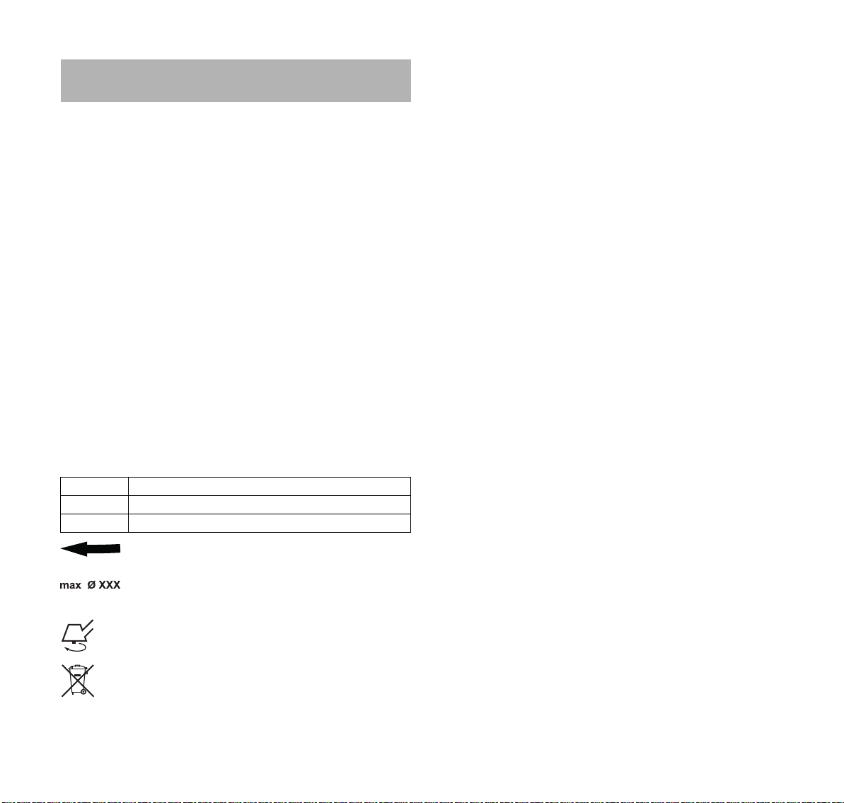
24 Specifications
English
24 Specifications
24.1 STIHL FSA 130 R
– Approved battery types:
– STIHL AR series
– STIHL AP series in combination with the STIHL AP
Battery Bag with Connecting Cord
– Weight without deflector or cutting attachment:
8.6 lbs. (3.9 kg)
– Length: 68.9 in. (1750 mm)
For technical information regarding the STIHL AR and AP
series batteries, see the product information accompanying
your battery.
For technical information regarding the STIHL AL 101, 300
and 500 series chargers, see the product information
accompanying your charger.
Batteries, chargers and other accessories sold separately.
Contact your authorized STIHL servicing dealer for pricing
and availability.
24.2 Symbols on the Power Tool and Deflector
Symbol Explanation
VVolt
DC Direct current
Symbol on the deflector showing proper
direction of rotation for the cutting attachment.
Maximum allowable diameter of the cutting
attachment
Rated speed of the cutting attachment
STIHL products must not be disposed of in the
household trash, but only in accordance with local,
state and federal laws and regulations and as
provided in this manual, @ 27.
24.3 Engineering Improvements
STIHL's philosophy is to continually improve all of its
products. As a result, engineering changes and
improvements are made from time to time. Therefore, some
changes, modifications and improvements may not be
covered in this manual. If the operating characteristics or the
appearance of your machine differs from those described in
this manual, please contact your STIHL dealer or the STIHL
distributor in your area for assistance.
24.4 FCC 15 Compliance Statement
This device complies with part 15 of the FCC Rules.
Operation is subject to the following two conditions:
– this device may not cause harmful interference.
– this device must accept any interference received,
including interference that may cause undesired
operation.
Note: This equipment has been tested and found to comply
with the limits for a Class B digital device, pursuant to part
15 of the FCC Rules. These limits are designed to provide
reasonable protection against harmful interference in a
residential installation. This equipment generates, uses and
can radiate radio frequency energy and, if not installed and
used in accordance with the instructions, may cause harmful
interference to radio communications. However, there is no
guarantee that interference will not occur in a particular
installation.
If this equipment does cause harmful interference to radio or
television reception, which can be determined by turning the
equipment off and on, the user is encouraged to try to
correct the interference by one or more of the following
measures:
– reorient or relocate the receiving antenna,
– increase the separation between the equipment and
receiver,
– connect the equipment to an outlet on a circuit different
from that to which the receiver is connected,
0458-725-8621-B
53
Page 56

English
– consult an authorized STIHL servicing dealer or an
experienced radio/TV technician for help.
Do not change or modify this product in any way unless
specifically allowed in this manual, since this could void your
authority to operate it.
24 Specifications
54
0458-725-8621-B
Page 57

25 Approved Deflector, Cutting Attachment, Handle and Harness Combinations
6
8
7
5
4
3
2
1
17
17
16
14
14
12
13
13
11
16
9
10
15
15
+
+
0000-GXX-3924-A1
18
15
15
18
25 Approved Deflector, Cutting Attachment, Handle and Harness Combinations
25.1 STIHL FSA 130 R
English
WARNING
To reduce the risk of personal injury from thrown objects and
contact with the cutting attachment, never operate the
trimmer / brushcutter without the proper deflector, loop
handle and harness, @ 5.7.4. Ensure that the deflector and
loop handle are properly mounted and adjusted at all times
while working.
0458-725-8621-B
WARNING
To reduce the risk of injury from loss of control and contact
with the cutting attachment, make sure your unit is equipped
with the proper handle, deflector and harness. Use grass
cutting metal blades and brush knives on this unit only if
equipped with a loop handle with barrier bar and harness.
55
Page 58

English
25 Approved Deflector, Cutting Attachment, Handle and Harness Combinations
The FSA 130 R is approved for use only with the following
cutting attachments:
Cutting Attachments Deflectors Handle Harnesses
Mowing heads with round
"quiet" line with a diameter of
0.095 in. (2.4 mm):
– AutoCut 25-2 (1)
– AutoCut C 26-2 (1)
– SuperCut 20-2 (2)
– DuroCut 20-2 (3)
– TrimCut 31-2 (4)
– FixCut 31-2 (5)
– Deflector for Mowing Heads
(9)
– Deflector for Metal Cutting
Attachments with Skirt and
Line Limiting Blade (10)
– Loop Handle (12)
– Loop Handle with Barrier
Bar (13)
– STIHL AR Backpack
Battery (14), optionally in
combination with Hip
Pad (15)
– STIHL Battery Belt with
STIHL AP Battery Bag with
Connecting Cord (17),
optionally in combination
with the Single
Harness (16)
–STIHL Battery
Backpack (18), optionally in
combination with Hip
Pad (15)
– Grass Cutting Blade
230-4(6)
– Grass Cutting Blade
230-8(7)
– Deflector for Metal Cutting
Attachments without
Skirt (11)
– Loop Handle with Barrier
Bar (13)
– STIHL AR Backpack
Battery (14) in combination
with Hip Pad (15)
– STIHL Battery Belt with
STIHL AP Battery Bag with
Connecting Cord (17) in
combination with the Single
Harness (16)
–STIHL Battery
Backpack (18) in
combination with Hip
Pad (15)
– Brush Knife 250-3(8)
56
0458-725-8621-B
Page 59

26 Replacement Parts and Equipment
English
26 Replacement Parts and Equipment
26.1 Genuine STIHL Replacement Parts
STIHL recommends the use of genuine STIHL replacement
parts. Genuine STIHL parts can be identified by the STIHL
part number, the logo and, in some cases, by the
STIHL parts symbol . The symbol may appear alone on
small parts.
27 Disposal
27.1 Disposal of the Power Tool
STIHL products must not be thrown in household trash or
disposed of except as outlined in this manual.
► Take the power tool, accessories and packaging to an
approved disposal site for environmentally friendly
recycling.
► Contact your authorized STIHL
latest information on disposal and recycling.
27.2 Battery Recycling
servicing dealer for the
STIHL is committed to the development of products
that are environmentally responsible. This
commitment does not stop when the product leaves
the authorized STIHL servicing dealer. STIHL has
partnered with the RBRC (Rechargeable Battery
Recycling Corporation) to promote the collection and
recycling of spent STIHL lithium ion batteries in the
United States and Canada.
The RBRC seal indicates that STIHL has prepaid for battery
recycling. RBRC has a toll free phone number (1-800-822-
8837) that connects you to information on battery recycling
locations and information on battery disposal bans or
restrictions in your area. You can also return your spent
battery to any authorized STIHL servicing dealer for
recycling free of charge.
28 Limited Warranty
28.1 STIHL Incorporated Limited Warranty Policy
This product is sold subject to the STIHL Incorporated
Limited Warranty Policy, available at
www.stihlusa.com/warranty.html. It can also be obtained
from your authorized STIHL dealer or by calling
1-800-GO-STIHL (1-800-467-8445).
WARNING
Handle discharged/depleted batteries carefully. Even if
believed to be discharged, lithium ion batteries may never
totally discharge and still may deliver a dangerous short
circuit current. If damaged or exposed to extreme
temperatures, they may leak, generate heat, catch fire or
explode.
► Observe all federal, state and local disposal rules and
regulations.
► Contact your authorized STIHL servicing dealer for the
latest information on waste disposal.
► Recycle depleted batteries promptly.
► Keep batteries away from children. Do not disassemble
and do not dispose of in fire.
0458-725-8621-B
28.2 STIHL Incorporated CALIFORNIA ZERO EMISSIONS CONTROL WARRANTY STATEMENT
For California only
YOUR WARRANTY RIGHTS AND OBLIGATIONS
The California Air Resources Board (CARB) and STIHL
Incorporated are pleased to explain the emissions control
system warranty on your 2020 and later small off-road zero
emission equipment motor.
In California, new equipment that uses small off-road zero
emission equipment motors must be designed, built, and
equipped to meet the State’s stringent anti-smog standards.
STIHL Incorporated must warrant the emissions control
57
Page 60

English
28 Limited Warranty
system on your small off-road zero emission equipment
motors for the periods of time listed below provided there
has been no abuse, neglect or improper maintenance of
your small off-road motor or equipment leading to the failure
of the emissions control system.
Your emissions control system may include parts such as
the zero emission equipment motor, motor controller, battery
and battery charger.
Where a warrantable condition exists, STIHL Incorporated
will repair your small off-road zero emission equipment
motor at no cost to you including diagnosis, parts, and labor.
MANUFACTURER’S WARRANTY RESPONSIBILITIES
The emissions control system on your small off-road
equipment motor is warranted for two years. If any emissionrelated part on your small off-road zero emission equipment
motor is defective, the part will be repaired or replaced by
STIHL Incorporated free of charge.
OWNER’S WARRANTY RESPONSIBILITIES
As the small off-road zero emission equipment motor owner,
you are responsible for the performance of the required
maintenance listed in your instruction manual. STIHL
Incorporated recommends that you retain all receipts
covering maintenance on your small off-road zero emission
equipment motor, but STIHL Incorporated cannot deny
warranty coverage solely for the lack of receipts or for your
failure to ensure the performance of all scheduled
maintenance.
As the small off-road zero emission equipment motor owner,
you should however be aware that STIHL Incorporated may
deny you warranty coverage if your small off-road zero
emission equipment motor or a part has failed due to abuse,
neglect, improper maintenance or unapproved
modifications.
You are responsible for presenting your small off-road zero
emission equipment motor to an authorized STIHL dealer as
soon as a problem exists. The warranty repairs should be
completed in a reasonable amount of time, not to exceed
30 days.
If you have any questions regarding your warranty rights and
responsibilities, please contact a STIHL customer service
representative at 1-800-467-8445 or you can write to
STIHL Incorporated
536 Viking Drive
P.O. Box 2015
Virginia Beach, VA
23452-2015
www.stihlusa.com
COVERAGE BY STIHL INCORPORATED
STIHL Incorporated warrants to the ultimate purchaser and
each subsequent purchaser that your small off-road zero
emission equipment motor is designed, built and equipped,
at the time of sale, to meet all applicable emission
regulations.
STIHL Incorporated also warrants to the initial purchaser
and each subsequent purchaser that your zero emission
equipment motor is free from defects in materials and
workmanship which cause the your zero emission
equipment motor to fail to conform to applicable emission
regulations for a period of two years.
DEFECTS WARRANTY PERIOD
The warranty periods will begin on the date the utility zero
emission equipment motor is purchased by the initial
purchaser. If any emission-related part on your zero
emission equipment motor is defective, the part will be
replaced by STIHL Incorporated at no cost to the owner.
Add-on or modified parts that are not exempted by CARB
may not be used. The use of any non-exempted add-on or
modified parts will be grounds for disallowing a warranty
claim. STIHL Incorporated will not be liable to warrant
failures of warranted parts caused by the use of a nonexempted add-on or modified part.
The warranty on emissions-related parts will be interpreted
as follows:
1)Any warranted part that is not scheduled for replacement
as required maintenance in the written instructions
required in the Emission Warranty Parts List (see below)
must be warranted for the warranty period defined in
58
0458-725-8621-B
Page 61

29 Trademarks
English
Subsection COVERAGE BY STIHL INCORPORATED,
see above. If any such part fails during the period of
warranty coverage, it must be repaired or replaced by the
manufacturer according to Subsection (4) below. Any
such part repaired or replaced under the warranty must be
warranted for the remaining warranty period.
2)Any warranted part that is scheduled only for regular
inspection in the written instructions required by the
Emission Warranty parts List (see below) must be
warranted for the warranty period defined in Subsection
COVERAGE BY STIHL INCORPORATED, see above. A
statement in such written instructions to the effect of
“repair or replace as necessary” will not reduce the period
of warranty coverage. Any such part repaired or replaced
under warranty must be warranted for the remaining
period.
3)Any warranted part that is scheduled for replacement as
required maintenance in the written instructions required
by the Emission Warranty Parts List (see below) must be
warranted for the period of time prior to the first scheduled
replacement point for that part. If the part fails prior to the
first scheduled replacement, the part must be repaired or
replaced by the zero emission equipment motor
manufacturer according to Subsection (4) below. Any
such part repaired or replaced under warranty must be
warranted for the remainder of the period prior to the first
scheduled replacement point for the part.
4)Repair or replacement of any warranted part under the
warranty must be performed at a warranty station at no
charge to the owner.
5)Notwithstanding the provisions of Subsection (4) above,
warranty services or repairs will be provided at all
manufacturer distribution centers that are authorized to
service the subject zero emission equipment motor.
6)The owner must not be charged for diagnostic labor that
leads to the determination that a warranted part is in fact
defective, provided that such diagnostic work is performed
at a warranty station.
WARRANTY WORK
STIHL Incorporated shall remedy warranty defects at any
authorized STIHL dealer or warranty station. Any such work
shall be free of charge to the owner if it is determined that a
warranted part is defective. Any manufacturer approved or
equivalent replacement part may be used for any warranty
maintenance or repairs on emission-related parts and must
be provided without charge to the owner. STIHL
Incorporated is liable for damages to other zero emission
equipment motor components caused by the failure of a
warranted part still under warranty.
EMISSION WARRANTY PARTS LIST
Motor, Battery, Battery Charger, Motor Controller
WHERE TO MAKE A CLAIM FOR WARRANTY SERVICE
Bring the STIHL product to any authorized STIHL dealer.
LIMITATIONS
The repair or replacement of any warranted part otherwise
eligible for warranty coverage may excluded from such
warranty coverage if STIHL Incorporated demonstrates that
the STIHL product has been abused, neglected, or
improperly maintained, and that such abuse, neglect, or
improper maintenance was the direct cause of the need for
repair or replacement of the part. That notwithstanding, any
adjustment of a component that has a factory installed, and
properly operating, adjustment limiting device is still eligible
for warranty coverage.
29 Trademarks
29.1 Registered Trademarks
STIHL
®
FARM BOSS
iCademy
MAGNUM
®
®
®
0458-725-8621-B
59
Page 62

English
TM
STIHL
Injection
30 Addresses
The color combination
orange-grey (U.S.
Registrations #2,821,860;
#3,010,057, #3,010,058,
#3,400,477; and
#3,400,476)
AutoCut
YARD BOSS
STIHL ROLLOMATIC
WOOD BOSS
®
®
®
®
MasterWrench Service
MotoMix
OILOMATIC
ROCK BOSS
STIHL Cutquik
®
®
®
®
STIHL DUROMATIC
STIHL Quickstop
STIHL WOOD BOSS
TIMBERSPORTS
®
®
®
®
®
29.2 Common Law Trademarks
4-MIX™ HT Plus™
BioPlus™ STIHL PowerSweep™
Easy2Start™ STIHL Protech™
EasySpool™ STIHL MiniBoss™
ElastoStart™ STIHL MotoPlus 4™
Ematic™ Master Control Lever™
STIHL Precision Series™ STIHL OUTFITTERS™
FixCut™ STIHL PICCO™
Micro™ TrimCut™
Pro Mark™ STIHL M-Tronic™
Quad Power™ STIHL HomeScaper Series™
Quiet Line™ STIHL PolyCut™
STIHL Arctic™ STIHL RAPID™
STIHL Compact™ STIHL SuperCut™
STIHL Interchangeable
Attachment Series™
TapAction™ STIHL Territory™
STIHL Multi-Cut HomeScaper
Series™
Any unauthorized use of these trademarks without the
express written consent of ANDREAS STIHL AG & Co. KG,
Waiblingen is strictly prohibited.
30 Addresses
30.1 STIHL Incorporated
STIHL Incorporated
536 Viking Drive
P.O. Box 2015
Virginia Beach, VA
23452-2015
This listing of trademarks is subject to change.
60
0458-725-8621-B
Page 63

Contenido
1 Introducción
2 Acerca de este manual de instrucciones
2.1 Palabras identificadoras
2.2 Símbolos en el texto
3 Componentes importantes
3.1 Motoguadaña / desmalezadora
3.2 Accesorios de corte y deflectores disponibles
3.3 Opciones de arneses para la batería
Manual de instrucciones originalImpreso en papel libre de cloro.
4 Símbolos de seguridad en los productos
4.1 Motoguadaña / desmalezadora
4.2 Deflectores para cabezas segadoras
4.3 Deflectores para accesorios de corte metálicos
4.4 Faldilla
4.5 Batería
5 INSTRUCCIONES IMPORTANTES DE
SEGURIDAD
5.1 Advertencias e instrucciones de seguridad
generales
5.2 Introducción
5.3 Uso previsto
5.4 Operador
5.5 Equipos de protección personal
5.6 Motoguadaña / desmalezadora
5.7 Uso de la motoguadaña / desmalezadora
Las tintas contienen aceites vegetales, el papel es reciclable.
5.8 Uso de los accesorios de corte
6 Mantenimiento, reparación y almacenamiento
6.1 Advertencias e instrucciones
7 Seguridad de la batería
7.1 Advertencias e instrucciones
8 Antes de empezar a trabajar
8.1 Preparación de la motoguadaña para el
funcionamiento
9 Carga de la batería
. . . . . . . . . . . . . . . . . . . . . . . . . . . . . . . . . . . . . . . .
. . . . . . . . . . . . . . . . . . . . . . . . . . . .
. . . . . . . . . . . . . . . . . . . . . . . . . . . . . . .
. . . . . . . . . . . . . . . . . . . . . . . . .
. . . . . . . . . . . . . . . . . . . . .
. . . . . . . . . . . . . . . . . . . . .
. . . . . . . . . . . . . . . . . . . . . . . . . . . . . . . . . . . . . . . . . . . . .
. . . . . . . . . . . . . . . . . . . . . . . . . . . . . . . . . . . . . . . . . . . . .
. . . . . . . . . . . . . . . . . . . . . . . . . . . . . . . . . . . . . . .
. . . . . . . . . . . . . . . . . . . . . . . . . . . . . . . . . . . . . . . . . .
. . . . . . . . . . . . . . . . . . . . . . . . . . . . . . . . . . . . . . . .
. . . . . . . . . . . . . . . . . . . . . . . . . . . . . . . . . . . . . . .
. . . . . . . . . . . . . . . . . . . . . . . . . . . . . . . . . . . . . . . . . . .
. . . . . . . . . . . . . . . . . . . .
. . . . . . . . . . . . . . . . . . . . .
. . . . . . . . . . . . . . . . . . . . .
. . . . . . . . . . . . . . . . . . . . . . .
. . . . . . . . . . . . . . . . . . . . . . . . . . . .
. . . . . . . . . . . . . . . . . . . . . . .
. . . . . . . . . . . . . . . . . . . . . . .
. . . . . . . . . . . . . . . . . . . . . . . . . . . . . . . . . . . . .
. . . . . . . . . . . . . . . . . . . . . . . . . . . . . . . . .
. . . . . . . . . . . .
. . . . . .
. . . . . . . . . . . . . . .
. . . . . . . . . . .
. . . . . . . . . . . . . . .
. . . . .
. . . . . . . . . . .
. . . . . .
9.1 Preparación del cargador para el funcionamiento
63
9.2 Carga
63
10 Diagnóstico por LED y señales acústicas
63
10.1 Batería de mochila STIHL AR
64
10.2 Batería AP de STIHL
64
11 Armado de la motoguadaña / desmalezadora
64
11.1 Montaje del mango tórico
65
11.2 Ajuste del mango tórico
66
11.3 Montaje de la barra de defensa
66
11.4 Instalación y retiro de un deflector
66
11.5 Montaje y retiro de una cabeza segadora
67
11.6 Montaje y retiro de un accesorio de corte
68
68
12 Uso de un arnés para batería
68
12.1 Batería de mochila STIHL AR
12.2 Batería de mochila STIHL
69
12.3 Cinturón para batería STIHL
. . . . . . . . . . . . . . . . . . . . . . . . . . . . . . . . . . . . . . . . . . . . . .
. . . . . . . . . . . . . . . . . . . . . .
. . . . . . . . . . . . . . . . . . . . . . . . . . . . . .
. . . . . . . . . . . . . . . . . . . . . . . . . .
. . . . . . . . . . . . . . . . . . . . . . . . . . . .
. . . . . . . . . . . . . . . . . . . .
metálico
. . . . . . . . . . . . . . . . . . . . . . . . . . . . . . . . . . . . . . . . . . . .
. . . . . . . . . . . . . . . . . . . . . .
. . . . . . . . . . . . . . . . . . . . . .
. . . . . . . . . . . . . . . . . . . . . . . . . .
. . . . . . . . . . . . . . . . . . . . . .
12.4 Colocación de la almohadilla para cadera en el
69
70
70
71
71
72
73
80
83
83
84
84
86
86
86
arnés de la batería
. . . . . . . . . . . . . . . . . . . . . . . . . . . . . . . .
13 Ajuste de la motoguadaña / desmalezadora
13.1 Equilibrado de la motoguadaña / desmalezadora
14 Inserción y retiro del cable de conexión
14.1 Colocación del cable de conexión
14.2 Retirada del cable de conexión
. . . . . . . . . . . . . . . . . . .
15 Encendido y apagado de la motoguadaña /
desmalezadora
15.1 Encendido
15.2 Apagado
. . . . . . . . . . . . . . . . . . . . . . . . . . . . . . . . . . .
. . . . . . . . . . . . . . . . . . . . . . . . . . . . . . . . . . . . . . . .
. . . . . . . . . . . . . . . . . . . . . . . . . . . . . . . . . . . . . . . . . .
16 Comprobación de la herramienta motorizada
16.1 Prueba de los controles
17 Durante el funcionamiento
17.1 Selección del nivel de potencia
. . . . . . . . . . . . . . . . . . . . . . . . . . .
. . . . . . . . . . . . . . . . . . . . . . . .
. . . . . . . . . . . . . . . . . . .
17.2 Uso de la motoguadaña / desmalezadora
17.3 Ajuste del hilo de nilón
. . . . . . . . . . . . . . . . . . . . . . . . . . . .
español / EE.UU
. . .
. . . . . . . . . . .
. . . . . .
. . . . . . . . . . . . . . . . .
. . . . . . . . . .
. . . . . . .
. .
. . . . . . . . . . .
. . . . . . . . . . . . . . . . .
. . . . . .
. . . . . . . . .
86
87
88
88
90
90
90
91
91
92
93
95
97
97
98
101
103
104
104
104
104
105
105
105
106
106
106
107
107
108
108
© ANDREAS STIHL AG & Co. KG 2020
0458-725-8621-B. VA3.G20.
0000007684_011_EA
0458-725-8621-B
Este manual de instrucciones está protegido por derechos de propiedad intelectual. Todos los derechos reservados, especialmente los derechos de reproducción, traducción y procesamiento con sistemas electrónicos.
61
Page 64

español / EE.UU
Contenido
18 Después de completar el trabajo
. . . . . . . . . . . . . . . . . .
18.1 Preparación para el transporte o el
almacenamiento
19 Transporte
19.1 Transporte de la herramienta motorizada
20 Almacenamiento
. . . . . . . . . . . . . . . . . . . . . . . . . . . . . . . . . . .
. . . . . . . . . . . . . . . . . . . . . . . . . . . . . . . . . . . . . . . .
. . . . . . . . . .
. . . . . . . . . . . . . . . . . . . . . . . . . . . . . . . . . .
20.1 Almacenamiento de la herramienta motorizada
21 Limpieza
21.1 Limpieza de la herramienta motorizada
. . . . . . . . . . . . . . . . . . . . . . . . . . . . . . . . . . . . . . . . . .
. . . . . . . . . . .
21.2 Limpie las superficies de contacto del cable de
conexión
22 Inspección y mantenimiento
22.1 Tabla de inspección y mantenimiento
. . . . . . . . . . . . . . . . . . . . . . . . . . . . . . . . . . . . . . . . . .
. . . . . . . . . . . . . . . . . . . . . . .
. . . . . . . . . . . . .
22.2 Inspección y mantenimiento de la motoguadaña
/ desmalezadora
22.3 Lubricación de la caja de engranajes
. . . . . . . . . . . . . . . . . . . . . . . . . . . . . . . . . .
. . . . . . . . . . . . . .
22.4 Sustitución del hilo de la motoguadaña con
cabeza segadora AutoCut 25-2
. . . . . . . . . . . . . . . . . . . .
22.5 Afilado y equilibrio de un accesorio de corte
metálico
23 Guía de solución de problemas
23.1 Motoguadaña / desmalezadora
24 Especificaciones
24.1 STIHL FSA 130 R
. . . . . . . . . . . . . . . . . . . . . . . . . . . . . . . . . . . . . . . . . . .
. . . . . . . . . . . . . . . . . . . .
. . . . . . . . . . . . . . . . . . . .
. . . . . . . . . . . . . . . . . . . . . . . . . . . . . . . . . .
. . . . . . . . . . . . . . . . . . . . . . . . . . . . . . . . .
24.2 Símbolos en la herramienta motorizada y el
deflector
24.3 Mejoramientos técnicos
. . . . . . . . . . . . . . . . . . . . . . . . . . . . . . . . . . . . . . . . . .
. . . . . . . . . . . . . . . . . . . . . . . . . . .
24.4 Declaración de cumplimiento con norma FCC 15
25 Combinaciones aprobadas de deflector,
accesorio de corte, mango y arnés
25.1 STIHL FSA 130 R
. . . . . . . . . . . . . . . . . . . . . . . . . . . . . . . . .
26 Piezas y equipos de repuesto
26.1 Piezas de repuesto originales de STIHL
27 Eliminación
. . . . . . . . . . . . . . . . . . . . . . . . . . . . . . . . . . . . . . .
27.1 Desecho de la herramienta motorizada
27.2 Reciclado de las baterías
28 Garantía limitada
. . . . . . . . . . . . . . . . . . . . . . . . . . . . . . . . . .
. . . . . . . . . . . . . . . . . . . . . . . . .
. . . . . . . . . . . . . . . .
. . . . . . . . . . . . . . . . . . . . .
. . . . . . . . . . .
. . . . . . . . . . . .
. . . .
. .
109
109
109
109
110
110
110
110
110
112
112
112
113
113
115
116
116
118
118
118
118
118
120
120
122
122
122
122
122
122
28.1 Política de garantía limitada de STIHL
Incorporated
. . . . . . . . . . . . . . . . . . . . . . . . . . . . . . . . . . . . . .
28.2 DECLARACIÓN DE GARANTÍA DE STIHL
Incorporated SOBRE SISTEMAS DE CONTROL
DE EMISIONES SEGÚN NORMAS DE
CALIFORNIA
29 Marcas comerciales
29.1 Marcas comerciales registradas
29.2 Marcas comerciales por ley común
30 Direcciones
30.1 STIHL Incorporated
. . . . . . . . . . . . . . . . . . . . . . . . . . . . . . . . . . . . .
. . . . . . . . . . . . . . . . . . . . . . . . . . . . . . .
. . . . . . . . . . . . . . . . . . .
. . . . . . . . . . . . . . . .
. . . . . . . . . . . . . . . . . . . . . . . . . . . . . . . . . . . . . . .
. . . . . . . . . . . . . . . . . . . . . . . . . . . . . . .
122
122
125
125
125
126
126
62
0458-725-8621-B
Page 65

1 Introducción
español / EE.UU
1Introducción
Gracias por su compra. La información que contiene este
manual lo ayudará a obtener el máximo rendimiento y
satisfacción de la motoguadaña, y a reducir el riesgo de
lesiones que supone su uso, si dicha información se
respeta.
Los términos empleados en este manual para designar la
herramienta motorizada variarán de acuerdo con los tipos
de accesorios de corte que pueden instalarse en la misma.
El término “motoguadaña” se usa para describir a un modelo
FS / FSA provisto con una cabeza para hilo de nilón o una
cabeza con cuchillas flexibles de plástico (por ejemplo: la
cabeza PolyCut). Una “desmalezadora” designa a una
máquina provista de una cuchilla metálica rígida. Muchos
modelos FS / FSA de STIHL, incluso la FSA 130, pueden
utilizarse ya sea como motoguadaña o como
desmalezadora. Por lo tanto, este manual describe a la
herramienta motorizada como una “motoguadaña /
desmalezadora”.
¡CONSERVE ESTE MANUAL!
Debido a que la motoguadaña / desmalezadora
es una herramienta de corte de velocidad alta,
es necesario tomar medidas de precaución para
reducir el riesgo de lesiones personales.
Lea este manual de instrucciones
detenidamente antes del uso y periódicamente
de allí en adelante. Aténgase a todas las
instrucciones de seguridad. El uso descuidado o
inadecuado puede causar lesiones graves o
mortales.
Pida a su concesionario de servicio STIHL autorizado que le
enseñe el manejo de la herramienta motorizada.
No preste ni alquile la herramienta motorizada sin este
manual de instrucciones. Solo permita que personas que
comprendan plenamente la información dada en este
manual utilicen la motoguadaña / desmalezadora.
Para obtener más información, o si no comprende alguna de
las instrucciones incluidas en este manual, visite
www.stihlusa.com o comuníquese con el concesionario de
STIHL.
ADVERTENCIA
Tal como se explicará a continuación en este manual, para
reducir el riesgo de lesiones personales, asegúrese de que
su máquina esté equipada con el mango, arnés y deflector
adecuados para el tipo de accesorio de corte que se está
utilizando. Utilice exclusivamente los accesorios de corte
autorizados específicamente por STIHL para usar con el
modelo FSA. Siempre use la ropa protectora y las gafas
protectoras adecuadas. No se debe permitir la proximidad
de otros, especialmente niños y animales en el área de
trabajo donde se esté utilizando la motoguadaña.
ADVERTENCIA
El uso de esta máquina puede ser peligroso. Si el hilo o la
cuchilla giratoria llega a entrar en contacto con su cuerpo, le
ocasionará una cortadura. Si entra en contacto con un
objeto macizo tal como rocas, vidrio o piezas metálicas,
podría lanzarlo directa o indirectamente hacia donde se
encuentren terceros o el operador. El contacto con dichos
objetos puede dañar los accesorios de corte y puede hacer
que las cuchillas se rompan, astillen o agrieten. Los objetos
lanzados, incluso las cabezas o las cuchillas rotas, pueden
provocar lesiones graves o mortales al operador o a
personas que se encuentren en su proximidad. Aténgase a
las precauciones de seguridad dadas en este manual para
reducir el riesgo de sufrir lesiones personales.
2 Acerca de este manual de
instrucciones
2.1 Palabras identificadoras
Este manual contiene información sobre seguridad a la que
usted debe prestar atención especial. Dicha información se
indica con los siguientes símbolos y palabras
identificadoras:
0458-725-8621-B
63
Page 66

español / EE.UU
3 Componentes importantes
PELIGRO
Identifica una situación de peligro que, de no evitarse,
causará lesiones graves o mortales.
ADVERTENCIA
Identifica una situación de peligro que, de no evitarse,
podría causar lesiones graves o mortales.
INDICACIÓN
Indica el riesgo de daños a la propiedad, incluidos la
máquina o sus componentes.
2.2 Símbolos en el texto
El siguiente símbolo tiene como finalidad ayudarlo a utilizar
este manual.
Hace referencia a un capítulo o subcapítulo designado
en este manual de instrucciones.
3 Componentes importantes
3.1 Motoguadaña / desmalezadora
2
1
#
2
6
7
8
9
3
4
5
10
11
12
13
14
0000-GXX-3080-A2
64
1 Tomacorriente
Tomacorriente para el cable de conexión de la batería.
2 Mango de control
Mango para la mano trasera del operador.
3LED
Indica el nivel de potencia de la máquina.
4 Pestillo de retención
Bloquea / desbloquea el gatillo. Fija el nivel de potencia
de la unidad cuando está en modo activo.
5 Bloqueo del gatillo
Se debe presionar cuando el pestillo de retención está
desbloqueado para poder activar el gatillo.
0458-725-8621-B
Page 67

3 Componentes importantes
8
4
0000-GXX-3081-A0
1
2
7
4
5
3
6
español / EE.UU
6 Gatillo
Activa el accesorio de corte cuando se presiona.
7 Argolla de transporte
Para conectar un arnés a la motoguadaña /
desmalezadora.
8 Mango circular
Mango para la mano delantera del operador.
9 Barra de defensa
Diseñada para reducir el riesgo de que el operador entre
en contacto accidentalmente con el accesorio de corte.
Este equipo es necesario cuando la unidad se usa con
una cuchilla metálica.
10 Tubo de mando
El vástago de la herramienta motorizada.
11 Abertura para el pasador de tope
Abertura que permite al operador bloquear el eje de
salida insertando el pasador de tope.
12 Pasador de tope
Bloquea el eje de salida cuando se monta un accesorio
de corte.
13 Caja de engranajes
Cubre el sistema de transmisión.
14 Tapón roscado
Sella la abertura de llenado de grasa de la caja de
engranajes.
# Chapa de identificación
Contiene los datos eléctricos y el número de serie del
producto.
3.2 Accesorios de corte y deflectores disponibles
1 Deflector para accesorios de corte metálicos
Diseñado para reducir el riesgo de lesiones causadas
por objetos lanzados y por el contacto con el accesorio
de corte. No está diseñado para contener cuchillas
metálicas fragmentadas o rotas.
2 Cuchilla para pasto
Cuchilla metálica para cortar pasto enmarañado y seco,
helechos, malezas y vegetación similar.
3 Cuchilla para matorrales
Cuchilla metálica para cortar pasto denso, malezas,
matorrales, arbustos y vegetación similar.
4 Cuchilla limitadora del hilo
Una cuchilla metálica colocada en el deflector que corta
el hilo de nilón a la longitud adecuada.
5Faldilla
Convierte ciertos deflectores STIHL para usarlos con
una cabeza segadora.
6 Protector para transporte
Diseñado para reducir el riesgo de lesionarse por el
contacto con un accesorio de corte metálico cuando se
transporta la máquina.
0458-725-8621-B
65
Page 68

español / EE.UU
4 Símbolos de seguridad en los productos
7 Deflector para cabezas segadoras
Diseñado para reducir el riesgo de lesiones causadas
por objetos lanzados y por el contacto con el accesorio
de corte.
8 Cabeza segadora
Cabeza para montar el hilo de nilón de la motoguadaña.
La FSA 130 se vende con una cabeza segadora AutoCut y
un deflector correspondiente. Se ofrecen otros artículos
como accesorios.
3.3 Opciones de arneses para la batería
6
4
1
2
3
5
4
2
Hay una variedad de opciones de arneses que pueden
usarse con la FSA 130. (Las baterías, los arneses y otros
accesorios se venden por separado).
1 Batería de mochila STIHL AR
Batería de mochila.
2 Cordón de conexión
Transmite la corriente eléctrica de la batería a la
herramienta motorizada.
3 Almohadilla para cadera
Se fija al arnés de mochila y ayuda a apoyar a la
motoguadaña.
4Enchufe
La parte del cordón de conexión que se enchufa en el
receptáculo de la herramienta motorizada.
5 Batería de mochila STIHL
Permite llevar hasta dos baterías serie AP en sus
espaldas.
6 Bolsa de batería AP con cable de conexión
Aloja una batería AP y la conecta con la herramienta
motorizada.
7 Cinturón para batería STIHL
Permite llevar hasta dos baterías serie AP en sus
caderas.
3
2
7 6
La herramienta FSA 130 puede recibir alimentación de una
batería de mochila serie AR de STIHL. Como alternativa,
puede recibir alimentación de una batería AP de STIHL
cuando se usa en combinación con una bolsa para batería
AP y cordón de conexión de STIHL.
66
4
La FSA 130 se vende con el arnés sencillo (no se ilustra).
Se ofrecen otros artículos como accesorios.
4 Símbolos de seguridad en los
productos
0000-GXX-3921-A3
4.1 Motoguadaña / desmalezadora
Los símbolos de seguridad siguientes se encuentran en la
motoguadaña / desmalezadora:
0458-725-8621-B
Page 69

4 Símbolos de seguridad en los productos
español / EE.UU
Para reducir el riesgo de lesiones, respete las
medidas de seguridad especificadas.
Lea y aténgase a todas las precauciones de
seguridad dadas en el manual de instrucciones.
El uso inadecuado puede provocar lesiones
personales graves o mortales o daños a la
propiedad.
Para reducir el riesgo de lesionarse los ojos,
siempre use gafas protectoras. Usar un casco
aprobado si existe un riesgo de lesionarse la
cabeza, @ 5.5.
Póngase botas gruesas con suela
antideslizante. Al trabajar con un accesorio de
corte metálico, utilice botas de seguridad con
punta de acero, @ 5.5.
Siempre use guantes de trabajo gruesos (por
ejemplo, de cuero u otro material resistente al
desgaste) para manejar la máquina o los
accesorios de corte metálicos, @ 5.5.
El contragolpe (empuje causado por la cuchilla)
puede ocasionar la pérdida de control de la
herramienta motorizada y causarle lesiones
graves o mortales al usuario o a personas en su
proximidad. Tenga sumo cuidado al usar una
cuchilla rígida para reducir el riesgo de lesiones,
@ 5.7.4.
Para reducir el riesgo de lesiones personales
causadas por objetos lanzados, revisar la zona
de trabajo y quite las piedras, vidrio, rocas,
objetos metálicos y otros objetos que pudieran
ser lanzados por el accesorio de corte, @ 5.7.4.
15m (50ft)
Para reducir el riesgo de lesiones
personales causadas por objetos
lanzados, mantener a las demás
personas a por lo menos 15 m (50 pies)
de distancia, @ 5.7.4.
Para reducir el riesgo de lesiones o daños a la
propiedad causados por el encendido
accidental, desconectar el cordón de conexión
toda vez que la motoguadaña / desmalezadora
no esté en uso, @ 5.7.
La caja de engranajes está caliente durante el
funcionamiento de la máquina. Para reducir el
riesgo de lesionarse, evite tocar la caja de
engranajes mientras está caliente luego del
funcionamiento, @ 6.
4.2 Deflectores para cabezas segadoras
Los siguientes símbolos pueden encontrarse en los
deflectores diseñados para utilizarse con cabezas
segadoras:
El deflector puede usarse en conjunto con las
cabezas segadoras.
El deflector no debe usarse en conjunto con las
cuchillas para cortar pasto.
El deflector no debe usarse en conjunto con las
cuchillas para matorrales.
El deflector no debe usarse en conjunto con las
cuchillas picadoras.
El deflector no debe usarse en conjunto con las
sierras circulares.
0458-725-8621-B
67
Page 70

español / EE.UU
4 Símbolos de seguridad en los productos
4.3 Deflectores para accesorios de corte metálicos
Los siguientes símbolos pueden encontrarse en los
deflectores diseñados para utilizarse con accesorios de
corte metálicos:
El deflector no debe usarse en conjunto con las
cabezas segadoras.
El deflector puede usarse en conjunto con las
cuchillas para cortar pasto.
El deflector puede usarse en conjunto con las
cuchillas para matorrales.
El deflector no debe usarse en conjunto con las
cuchillas picadoras.
El deflector no debe usarse en conjunto con las
sierras circulares.
4.5 Batería
Los símbolos de seguridad siguientes se encuentran en la
batería de mochila serie AR y en la batería serie AP.
Para reducir el riesgo de lesiones, respete las
medidas de seguridad especificadas.
Lea y respete todas las precauciones de
seguridad dadas en el manual de instrucciones
de la batería y en el manual de la herramienta
STIHL que utiliza esta batería. El uso
inadecuado puede provocar lesiones personales
graves o mortales o daños a la propiedad.
Para reducir el riesgo de lesiones personales o
daños a la propiedad debido a incendios,
explosiones o quemaduras, incluidas las
quemaduras químicas, no desarme, aplaste,
deje caer, dañe o caliente la unidad a más de
100°C (212°F). Nunca la exponga al fuego ni la
incinere, @ 7.
Para reducir el riesgo de lesiones personales o
daños a la propiedad debido a un incendio, use
y almacene la batería solo dentro de un rango
de temperatura ambiente de -10°C a 50°C (14°F
a 122°F), @ 7.
4.4 Faldilla
Cuando se utiliza un deflector diseñado para usarse con un
accesorio de corte metálico o una cabeza segadora, la
faldilla deberá montarse de modo seguro según las
instrucciones impresas en la parte inferior del deflector
antes de trabajar con una cabeza segadora.
Se puede encontrar el siguiente símbolo en la faldilla:
Este deflector puede usarse junto con cabezas
segadoras.
68
Baterías tipo mochila AR 900, 1000, 2000, 3000
Para reducir el riesgo de lesiones personales o
daños a la propiedad causados por un
cortocircuito, un incendio o una explosión,
mantenga la unidad seca. Protéjala contra la
lluvia, el agua y las condiciones húmedas.
Nunca la sumerja en agua u otros líquidos,
@ 7.
Baterías tipo mochila AR L
Para reducir el riesgo de lesiones personales o
daños a la propiedad causados por un
cortocircuito, un incendio o una explosión,
mantenga la unidad seca. Nunca la sumerja en
agua u otros líquidos, @ 7.
0458-725-8621-B
Page 71

5 INSTRUCCIONES IMPORTANTES DE SEGURIDAD
español / EE.UU
Baterías serie AP
Para reducir el riesgo de lesiones personales o
daños a la propiedad causados por un
cortocircuito, un incendio o una explosión,
mantenga la unidad seca. Nunca la sumerja en
agua u otros líquidos, @ 7.
Las baterías se venden por separado.
5 INSTRUCCIONES
IMPORTANTES DE
SEGURIDAD
5.1 Advertencias e instrucciones de seguridad generales
Esta sección contiene las advertencias e instrucciones de
seguridad generales prescritas para motoguadañas
eléctricas manuales motorizadas. En secciones posteriores
de este manual se proporcionan otras advertencias e
instrucciones importantes.
ADVERTENCIA
Para reducir el riesgo de incendios, choques eléctricos y
lesiones, cuando use motoguadañas eléctricas, siempre
siga las precauciones de seguridad básicas, entre las que
se incluyen las siguientes:
LEA TODAS LAS INSTRUCCIONES ANTES DE USAR LA
MOTOGUADAÑA
1)Evite los entornos peligrosos: no utilice motoguadañas en
lugares húmedos ni mojados.
2)No use la máquina bajo la lluvia.
3)Mantenga alejados a los niños. Todas las demás
personas deben mantenerse a una distancia prudencial
de la zona de trabajo.
4)Use vestimenta apropiada: no lleve ropa suelta ni joyas.
Podrían quedar atrapadas en las piezas en movimiento.
Use guantes de trabajo gruesos (por ejemplo, de cuero o
de otro material resistente al desgaste) y calzado
resistente cuando trabaje a la intemperie. Si tiene el pelo
largo, cúbraselo con una protección adecuada.
5)Use gafas de seguridad. Siempre utilice una máscara o
mascarilla contra el polvo cuando trabaje en un lugar
polvoriento.
6)Utilice la herramienta apropiada para el trabajo. No use
una herramienta con fines distintos de los previstos para
ella.
7)Evite los arranques accidentales: no transporte la
motoguadaña con el dedo sobre el gatillo. Asegúrese de
que la motoguadaña está apagada cuando inserte el
cable de conexión.
8)No fuerce la motoguadaña: funciona mejor y con menos
riesgo de lesiones si se usa a la velocidad para la que fue
diseñada.
9)No extienda los brazos más allá de lo necesario:
mantenga el equilibrio y los pies bien apoyados en todo
momento.
10)Permanezca alerta: preste atención a lo que está
haciendo. Aplique el sentido común. No maneje la
motoguadaña cuando esté cansado.
11)Guarde la motoguadaña bajo techo: cuando no utilice la
motoguadaña, guárdela bajo techo, en un lugar seco y
bajo llave, fuera del alcance de los niños y sin la batería.
12)Cuide la motoguadaña: mantenga el accesorio de corte
limpio para obtener el mejor rendimiento y para reducir el
riesgo de lesiones. Siga las instrucciones cuando lubrique
la máquina y cambie sus accesorios. Mantenga los
mangos secos, limpios y libres de aceite y grasa.
13)Revise las piezas dañadas: antes de seguir usando la
motoguadaña, revise minuciosamente el protector o
cualquier otra pieza que esté dañada para verificar que
funcionarán correctamente y que cumplirán la función
para la que están previstas. Compruebe la alineación de
las piezas móviles y si estas tienen agarrotamiento; si hay
piezas rotas, el montaje de las piezas y toda condición
que pueda afectar su funcionamiento. Si un protector u
0458-725-8621-B
69
Page 72

español / EE.UU
5 INSTRUCCIONES IMPORTANTES DE SEGURIDAD
otra pieza tiene daños, deberá sustituirse o repararse
debidamente en un centro de servicio autorizado, salvo
que en este manual se indique lo contrario.
14)Inspeccione el cable de conexión periódicamente. Si
está dañado, solicite a un taller autorizado que lo repare.
15)Mantenga los protectores en su lugar y en buenas
condiciones.
16)Mantenga las cuchillas metálicas bien afiladas.
17)Mantenga las manos y los pies alejados de la zona de
corte y del accesorio de corte.
GUARDE ESTAS INSTRUCCIONES
5.2 Introducción
ADVERTENCIA
■ El uso de esta máquina puede ser peligroso. Si el hilo o la
cuchilla giratoria llegan a entrar en contacto con su
cuerpo, le ocasionará una cortadura. Si entra en contacto
con un objeto macizo tal como rocas, vidrio o piezas
metálicas, podría despedirlo o lanzarlo directa o
indirectamente hacia donde se encuentren terceros o el
operador. El contacto con dichos objetos puede dañar los
accesorios de corte y puede hacer que las cuchillas se
rompan, astillen o agrieten. Los objetos lanzados, incluso
las cabezas o las cuchillas rotas, pueden provocar
lesiones graves o mortales al operador o a personas que
se encuentren en su proximidad. Tal como se explicará a
continuación en este manual, para reducir el riesgo de
lesión personal:
– Asegúrese de que su máquina esté equipada con el
mango, el arnés el deflector adecuados para el tipo
de accesorio de corte que se está utilizando.
– Utilice exclusivamente los accesorios de corte
autorizados específicamente por STIHL para usar
en su modelo de motoguadaña.
■ No preste ni alquile nunca su motoguadaña sin entregar
el manual de instrucciones. Asegúrese de que todas las
personas que utilicen el dispositivo hayan comprendido la
información que contiene este manual. Pida a su
concesionario que le enseñe el manejo de la
motoguadaña. Respete todas las leyes, disposiciones,
reglamentos y normas del caso.
5.3 Uso previsto
ADVERTENCIA
■ Cuando tiene una cabeza segadora o una hoja para
pasto, esta motoguadaña / desmalezadora puede usarse
para cortar pasto denso, malezas y vegetación similar.
Cuando se le monta una cuchilla para matorrales, puede
usarse para cortar pasto denso, malezas, arbustos y
vegetación similar cuyo diámetro mida 20 mm (0,8 pulg)
como máximo.
– No debe usarse para ningún otro fin.
■ El uso indebido puede dar por resultado lesiones
personales o daños a la propiedad, incluyendo daños a la
herramienta motorizada.
– Utilice la herramienta motorizada únicamente de la
manera descrita en este manual.
– Nunca intente modificar ni anular los controles ni los
dispositivos de seguridad de la motoguadaña /
desmalezadora de ningún modo.
– Nunca utilice una motoguadaña / desmalezadora
que haya sido modificada o alterada, apartándose
de su diseño original.
– Asegúrese de leer y respetar todas las advertencias
e instrucciones de la batería y el cargador antes de
cargarla o de empezar a trabajar.
■ Esta herramienta motorizada puede recibir alimentación
de una mochila de batería serie AR de STIHL. Como
alternativa, puede recibir alimentación de una batería AP
de STIHL cuando se usa en combinación con una bolsa
para batería AP y cordón de conexión de STIHL.
Las baterías, los cargadores y otros accesorios se venden
por separado.
70
0458-725-8621-B
Page 73

5 INSTRUCCIONES IMPORTANTES DE SEGURIDAD
español / EE.UU
5.4 Operador
ADVERTENCIA
■ El uso de una herramienta motorizada puede ser fatigoso.
El operador debe hallarse en buenas condiciones tanto
físicas como mentales. Para reducir el riesgo de lesiones
personales causadas por fatiga o pérdida del control:
– Consulte con su médico antes de trabajar con una
herramienta motorizada si usted padece de alguna
condición de salud que pudiera ser agravada por el
trabajo extenuante.
– No utilice la herramienta motorizada si se encuentra
bajo la influencia de alguna sustancia (drogas,
alcohol o medicamentos, etc.) que pudiera
perjudicar su visión, equilibrio, destreza o criterio.
– Esté alerta. No use la herramienta motorizada si
está cansado. Tómese un descanso si se siente
cansado.
– No permita que menores de edad utilicen la
herramienta motorizada.
■ Según los conocimientos actuales de STIHL, el motor
eléctrico de esta herramienta motorizada no debería
interferir con un marcapasos.
– Sin embargo, las personas con marcapasos u otro
dispositivo médico implantado deben consultar a su
médico y al fabricante del dispositivo antes de
utilizar esta herramienta motorizada.
5.5 Equipos de protección personal
ADVERTENCIA
■ Hasta un deflector debidamente instalado y ajustado
podría no proteger al operador de todos los objetos
lanzados o despedidos por el accesorio de corte. Los
objetos arrojados o lanzados por el accesorio también
pueden rebotar y golpear al operador. Para reducir el
riesgo de lesiones personales:
– Siempre use ropa adecuada y trajes protectores,
incluidas gafas protectoras adecuadas.
■ Se podría causar la pérdida de control y cortaduras
graves si el cabello, la ropa o la vestimenta entran en
contacto con el accesorio de corte o de otra manera sean
atrapados por los componentes de la motoguadaña /
desmalezadora. Para reducir el riesgo de lesiones
personales graves:
– Use ropa resistente y ajustada que
permita una completa libertad de
movimiento.
– Use monos o pantalones largos hechos
de un material grueso para protegerse
las piernas. No use pantalones cortos.
– Evite el uso de chaquetas sueltas, bufandas,
corbatas, pantalones acampanados o con vueltas,
joyas o cualquier otra vestimenta que pueda
engancharse en las ramas, matorrales o el
accesorio de corte en movimiento.
– Sujétese el cabello por encima de los hombros antes
de empezar a trabajar.
■ Para reducir el riesgo de lesiones oculares:
– Siempre utilice gafas o anteojos
protectores bien ajustados con
protección lateral resistentes a impactos
y que porten designaciones que indiquen
que cumplen con la norma
ANSI Z87 «+».
– Si existe el riesgo de lesionarse el rostro, STIHL
recomienda usar también una careta o protector
facial adecuado sobre las gafas o anteojos de
seguridad. Al trabajar con un accesorio de corte
metálico, utilice siempre un protector facial.
– Usar un casco aprobado si existe un riesgo de
lesionarse la cabeza.
0458-725-8621-B
71
Page 74

español / EE.UU
5 INSTRUCCIONES IMPORTANTES DE SEGURIDAD
■ Es muy importante tener una buena superficie de apoyo
para los pies. Para ayudar a mantener un punto de apoyo
seguro y reducir el riesgo de lesiones mientras trabaja:
– Póngase un calzado sólido con suela
antideslizante. Nunca use sandalias,
ojotas, zapatos que dejen los dedos
descubiertos ni calzado de ese tipo. Al
trabajar con un accesorio de corte
metálico, utilice botas de seguridad con
punta de acero.
■ Para mejorar el manejo y ayudar a proteger las manos:
– Siempre use guantes gruesos y
antideslizantes de cuero o de otro
material resistente al desgaste al
manipular la motoguadaña /
desmalezadora.
– Use siempre guantes resistentes al
montar o manipular un accesorio de
corte metálico.
5.6 Motoguadaña / desmalezadora
ADVERTENCIA
■ Para reducir el riesgo de descarga eléctrica:
– No exponga la herramienta motorizada al agua o a
la humedad excesiva.
– Almacene la herramienta motorizada bajo techo.
■ Si el accesorio de corte en movimiento llega a tener
contacto con su persona, causará laceraciones graves.
Para reducir el riesgo de este tipo de lesiones:
– Mantenga las manos, los pies y cualquier otra parte
del cuerpo lejos del accesorio de corte.
– No toque nunca con las manos ni con ninguna parte
del cuerpo un accesorio de corte en movimiento.
– Nunca utilice la motoguadaña / desmalezadora si
tiene un deflector dañado o faltante.
■ Para reducir el riesgo de lesiones personales al operador
y a terceros causadas por el contacto con la cuchilla, el
hilo y los objetos lanzados:
– Asegúrese de que su máquina esté
equipada con el deflector, mango y
arnés adecuados para el tipo de
accesorio de corte que se está
utilizando. Mantenga siempre el
deflector y la faldilla, en su caso, bien
ajustados.
– El uso de algunos accesorios de corte le obligará a
cambiar el deflector, la barra de defensa y/o el
arnés. Consulte el capítulo @ 25 de este manual
para ver las configuraciones aprobadas del
accesorio de corte, el deflector, el mango y el arnés.
■ Para reducir el riesgo de lesiones personales al operador
y a los espectadores:
– Retire siempre el cable de conexión
antes de armar, transportar, ajustar,
inspeccionar, limpiar, darle servicio o
mantenimiento o guardar la
motoguadaña / desmalezadora.
Desconecte el cordón de conexión en
caso de una avería o una emergencia y
siempre que la herramienta motorizada
no esté en uso.
– Nunca deje la herramienta motorizada desatendida
cuando esté conectada a la batería.
■ Aunque algunos accesorios no autorizados podrían
encajar con la motoguadaña / desmalezadora STIHL, su
uso podría resultar extremadamente peligroso. Utilice
únicamente los accesorios suministrados por STIHL o
expresamente autorizados por STIHL para usarse con
este modelo específico de máquina.
– Use solo los accesorios suministrados o
expresamente aprobados por STIHL.
– Nunca modifique esta motoguadaña /
desmalezadora en manera alguna.
– Nunca intente modificar ni anular los controles ni los
dispositivos de seguridad de la motoguadaña /
desmalezadora de ningún modo.
72
0458-725-8621-B
Page 75

5 INSTRUCCIONES IMPORTANTES DE SEGURIDAD
español / EE.UU
– Nunca utilice una motoguadaña / desmalezadora
que haya sido modificada o alterada, apartándose
de su diseño original.
– Para obtener una lista de accesorios de corte
autorizados por STIHL para uso con su máquina,
junto con las configuraciones aprobadas del
deflector, del mango y del arnés, consulte el capítulo
@ 25 de este manual de instrucciones, o el
catálogo “Accesorios de corte, Piezas y Accesorios”
de STIHL, disponible de su concesionario o en
www.stihlusa.com.
■ Si la herramienta motorizada o la batería se deja caer o
sufre algún impacto fuerte similar:
– Asegúrese de que no se haya dañado, de que esté
en buenas condiciones y de que funcione
correctamente antes de seguir con el trabajo.
– Compruebe que los controles y dispositivos de
seguridad funcionen correctamente.
– Si se indican mensajes de error en los LED de la
batería, @ 23.
– Nunca trabaje con una herramienta motorizada o
batería que esté averiada o funcione mal. En caso
de dudas, solicite al concesionario autorizado de
STIHL que revise la herramienta motorizada y la
batería.
■ Si la herramienta motorizada o la batería se avería, no
funciona debidamente, ha sido dejado a la intemperie, se
expone a condiciones húmedas o cae en agua u otro
líquido, sus componentes podrían no funcionar
debidamente y los dispositivos de seguridad podrían
quedar inoperantes. Para reducir el riesgo de lesiones
personales y daños a la propiedad:
– Lleve la herramienta motorizada y la batería al
concesionario autorizado de STIHL para que sean
revisadas antes de continuar utilizándolas.
■ Los repuestos genuinos STIHL han sido diseñados
específicamente para su herramienta motorizada y
satisfacen los requisitos de seguridad y de desempeño. El
uso de componentes no autorizados o no aprobados por
STIHL puede causar lesiones graves o mortales y daños
a la propiedad.
– STIHL recomienda que solo se utilicen repuestos
STIHL idénticos.
5.7 Uso de la motoguadaña / desmalezadora
5.7.1 Antes de usar
ADVERTENCIA
■ Un uso inadecuado o no autorizado puede causar
lesiones personales o daños materiales.
– Utilice la motoguadaña / desmalezadora únicamente
como se describe en este manual de instrucciones.
■ El accesorio de corte y el deflector deben formar una
combinación aprobada.
– No use discos de sierra en esta
motoguadaña / desmalezadora.
– Lea y siga las instrucciones sobre cómo seleccionar
el accesorio de corte y el deflector correctos, @ 25.
■ El accesorio de corte debe estar instalado y ajustado
correctamente antes de empezar a trabajar. Si no se
utilizan las piezas adecuadas para montar el accesorio de
corte, la cuchilla o la cabeza segadora podrían salir
despedidas y causar lesiones graves al operador o a las
personas que se encuentren en los alrededores.
– Lea y siga las instrucciones para montar el
accesorio de corte, el deflector y el mango, @ 11.
– Nunca monte un accesorio de corte en la
motoguadaña / desmalezadora si no ha instalado
antes correctamente todas las piezas (por ejemplo:
tuercas, tornillos, arandelas de empuje, placas de
empuje, etc.).
– Antes de empezar a trabajar, compruebe si hay
piezas flojas (tuercas, tornillos, etc.), si la cabeza
presenta grietas o daños y si la hoja está agrietada,
combada, deformada o dañada.
0458-725-8621-B
73
Page 76

español / EE.UU
5 INSTRUCCIONES IMPORTANTES DE SEGURIDAD
– Sustituya las cabezas o las cuchillas que estén
dañadas antes de usar la herramienta motorizada.
– Asegúrese de mantener los accesorios de corte
metálicos siempre bien afilados.
■ Utilizar únicamente una combinación de accesorio de
corte y deflector aprobada es extremadamente importante
para garantizar el máximo desempeño de corte y para
reducir el riesgo de lesiones personales causadas por
objetos que salen despedidos o por contacto con el
accesorio de corte.
– Para reducir el riesgo de lesiones graves, nunca use
un hilo de alambre o reforzado con metal ni ningún
otro material en lugar del hilo de corte de nilón
recomendado. Podrían desprenderse pedazos de
alambre, que podrían salir despedidos a gran
velocidad contra el operador o contra otras
personas.
■ El uso de una motoguadaña / desmalezadora que se ha
modificado, que está dañada, mal ajustada o no se ha
mantenido debidamente, o que no se ha montado por
completo y de forma segura, puede derivar en un fallo de
funcionamiento y aumentar el riesgo de lesiones
personales graves o mortales.
– Nunca utilice una motoguadaña / desmalezadora
que haya sido modificada, que esté dañada o mal
mantenida, o que no se haya montado
completamente y de forma segura.
– Verifique siempre que la unidad está en buenas
condiciones y que funciona correctamente antes de
empezar a usarla; preste especial atención al
pestillo de retención, al bloqueo del gatillo, al gatillo,
al deflector, al arnés y al accesorio de corte.
– Asegúrese de que el pestillo de retención, el
bloqueo del gatillo y el gatillo se mueven libremente,
y de que regresan siempre a su posición al soltarlos.
El gatillo no debe poder apretarse hasta que se
desbloquea el pestillo de retención y se pulsa el
bloqueo del gatillo.
– Nunca intente modificar ni anular en modo alguno
los controles ni los dispositivos de seguridad.
– El accesorio de corte debe engranarse únicamente
cuando la motoguadaña / desmalezadora está
conectada a una batería, el pestillo de retención
está desbloqueado y se han apretado el bloqueo del
gatillo y el gatillo.
– Si su motoguadaña / desmalezadora o alguno de
sus componentes, incluida la batería, ha sufrido
daños o no funciona debidamente, lleve la unidad a
su concesionario de servicio autorizado de STIHL.
No utilice la unidad si no se ha solucionado el
problema.
■ Antes de insertar el cable de conexión de la batería en la
toma de la herramienta motorizada:
– Compruebe si los contactos eléctricos del
tomacorriente y del enchufe del cable de conexión
están corroídos o si contienen materia extraña.
Manténgalos limpios.
– Si el tomacorriente está sucio o corroído, lleve la
unidad a su concesionario de servicio STIHL
autorizado antes de usarla.
– Nunca use una batería que no funcione
correctamente, que esté dañada, agrietada,
deformada o pierda líquido.
– Lea y siga las instrucciones de encendido de la
herramienta motorizada, @ 15.1.
■ Para reducir el riesgo de lesiones personales graves o
mortales provocadas por un arranque accidental:
– Asegúrese de que el pestillo de retención está en la
posición de bloqueo y de que el gatillo está en la
posición de apagado antes de insertar el cable de
conexión de la batería.
– Nunca acarree la unidad con el dedo en el gatillo.
– Suelte el gatillo antes de retirar el cable de conexión.
74
0458-725-8621-B
Page 77

5 INSTRUCCIONES IMPORTANTES DE SEGURIDAD
0000-GXX-3089-A2
español / EE.UU
– Retire el cable de conexión antes de
montar, transportar, ajustar,
inspeccionar, limpiar, darle servicio o
mantenimiento o guardar la
motoguadaña / desmalezadora. Retire el
cable de conexión si detecta un fallo de
funcionamiento o en caso de
emergencia, y siempre que la
herramienta motorizada no esté en uso.
– Nunca deje la herramienta motorizada desatendida
cuando esté conectada a la batería.
– Nunca guarde la herramienta motorizada con el
cable de conexión enchufado en la toma de la
herramienta motorizada.
■ Antes de encender su motoguadaña / desmalezadora, dé
los pasos que figuran a continuación para reducir el riesgo
de sufrir lesiones causadas por objetos que salen
despedidos, por la pérdida del control sobre la máquina o
por contacto accidental con el accesorio de corte:
– Asegúrese de mantener el accesorio de corte
alejado de su cuerpo y de otros obstáculos y
objetos, incluido el suelo.
– Lea y siga a las instrucciones de encendido de la
motoguadaña / desmalezadora, @ 15.1.
5.7.2 Sujeción y control de la motoguadaña / desmalezadora
– Nunca intente manejar la motoguadaña /
desmalezadora con una sola mano.
■ Para reducir el riesgo de perder el control y sufrir lesiones
graves o mortales, o provocárselas a las personas que se
encuentran cerca:
– Siempre sujete la herramienta motorizada
firmemente con las dos manos cuando trabaje con
ella.
– Agarre firmemente los mangos con todos los dedos,
manteniéndolos sujetos entre los dedos índice y
pulgar (vea la ilustración).
– Coloque la herramienta motorizada de modo que
todos los miembros de su cuerpo estén alejados del
accesorio de corte siempre que el cable de conexión
esté insertado.
■
ADVERTENCIA
■ Para sujetar con firmeza y controlar correctamente la
motoguadaña / desmalezadora:
– Mantenga los mangos limpios y secos en todo
momento. Protéjalos de la humedad, del alquitrán,
del aceite, de la grasa y de la resina.
■ Manejar la motoguadaña / desmalezadora con una sola
mano es extremadamente peligroso, porque se puede
perder el control sobre la máquina. Para reducir el riesgo
de que el operador o las personas de los alrededores
sufran lesiones graves o mortales causadas por una
pérdida de control:
0458-725-8621-B
■ Cuando se monta en la unidad un accesorio de corte
metálico, el operador debe tomar precauciones
especiales para reducir el riesgo de que se produzcan
lesiones graves por una pérdida de control o por contacto
accidental con la cuchilla:
– El operador debe montar el deflector y la barra de
defensa adecuados tal como se indica en este
manual, @ 11.3 y @ 11.4.
– El operador debe usar un arnés, @ 12.
75
Page 78

español / EE.UU
0000-GXX-3915-A2
5 INSTRUCCIONES IMPORTANTES DE SEGURIDAD
– Durante el funcionamiento, el operador debe sujetar
el mango trasero con la mano derecha y el mango
delantero, con la mano izquierda. Esto se aplica a
todos los operadores, incluidos aquellos que sean
zurdos. Trabajar con las manos en esta posición le
permitirá controlar eficazmente las fuerzas reactivas
que se producen cuando se trabaja con una cuchilla
metálica.
■
■ Si se trabaja con el accesorio de corte sobre el nivel del
suelo o en perpendicular al suelo, aumenta el riesgo de
lesiones causadas por objetos que salen despedidos.
Además, en esta posición queda descubierta una mayor
porción del accesorio de corte, lo que dificulta el control
de la máquina y aumenta, por tanto, el riesgo de lesiones.
Para reducir el riesgo de sufrir lesiones graves o mortales
por una pérdida del control o por objetos que salen
despedidos:
– Mantenga el accesorio de corte a nivel del suelo,
paralelo al mismo.
■ Para reducir el riesgo de que el operador o las personas
de los alrededores sufran lesiones graves o mortales por
contacto con el accesorio de corte:
– Mantenga las manos, los pies y
cualquier otra parte de su cuerpo lejos
del accesorio de corte.
– No toque nunca con las manos ni con
ninguna otra parte del cuerpo un
accesorio de corte en movimiento.
– No toque el accesorio de corte cuando el cable de
conexión esté insertado en la herramienta
motorizada.
■ Para reducir el riesgo de que el operador o las personas
que se encuentren cerca sufran lesiones graves o
mortales causadas por una pérdida de control, asegúrese
de mantener el equilibrio y los pies bien apoyados en todo
momento:
– Asegúrese de mantener el equilibrio y de tener los
pies bien apoyados en todo momento.
– Tenga especial cuidado cuando trabaje en terrenos
con mucha vegetación o húmedos, y preste atención
siempre a posibles obstáculos ocultos, como
tocones, raíces, piedras, hoyos y zanjas.
– Proceda con extrema precaución cuando trabaje en
declives o en terrenos irregulares, ya que la batería
puede alterar su centro de gravedad.
– Para no perder la estabilidad, retire siempre las
ramas caídas, los arbustos, el material cortado y
cualquier otro objeto o vegetación que pueda
aumentar el riesgo de resbalarse, tropezarse o caer.
– Nunca trabaje con la máquina por encima del nivel
de su cintura.
– No extienda los brazos más de lo necesario.
76
0458-725-8621-B
Page 79

5 INSTRUCCIONES IMPORTANTES DE SEGURIDAD
español / EE.UU
■ Mantenga la motoguadaña / desmalezadora equilibrada,
para poder controlarla adecuadamente y fatigarse menos
durante el uso.
– Ajuste la posición del mango circular y del arnés
para alcanzar y mantener una posición de trabajo
cómoda y eficaz, @ 13.
■ Para reducir el riesgo de lesionarse por un tropiezo con el
cable de conexión o por la pérdida del control sobre la
herramienta motorizada:
– Ajuste las correas del arnés de la mochila de batería
de modo que la placa quede firme y cómoda contra
su espalda. Nunca llev e una batería tipo mo chila AR
o una mochila de batería AP con las correas sobre
solo uno de sus hombros.
– Si utiliza la bolsa de batería AP de STIHL con cable
de conexión, asegúrese de que está fijada de modo
seguro al cinturón para batería STIHL, a la mochila
de batería STIHL o a otro cinturón de trabajo de
soltado rápido.
– Siempre coloque y asegure el cable de conexión de
modo que no le impida aplicar una técnica de trabajo
adecuada ni controlar la motoguadaña /
desmalezadora. Asegure el cable de conexión como
se indica en el manual de instrucciones de su
batería tipo mochila AR, de su bolsa de batería AP
con cable de conexión, del cinturón de batería o de
la mochila de batería STIHL.
– Mantenga el cable de conexión alejado del
accesorio de corte.
– Preste atención a la ubicación del cable de conexión
mientras trabaja. Evite que entre en contacto con el
accesorio de corte o que se enganche en otros
objetos: podría hacerle perder el equilibrio o el
control y provocar lesiones personales graves y
daños materiales.
5.7.3 Condiciones de trabajo
ADVERTENCIA
■ Utilice la motoguadaña / desmalezadora únicamente en
condiciones de buena visibilidad y bajo luz diurna
favorable.
– Posponga los trabajos si el tiempo está ventoso, con
neblina, lluvioso o inclemente.
■ La motoguadaña / desmalezadora es una máquina para
una sola persona.
– No se debe permitir la proximidad de otras
personas, especialmente de niños, ni de animales
en los lugares donde se esté utilizando la máquina.
– Apáguela de inmediato si otra persona se le acerca.
■ Para reducir el riesgo de lesiones a los espectadores y
usuarios no autorizados:
– Nunca deje la motoguadaña / desmalezadora
desatendida mientras esté conectada a una batería.
– Apague la máquina y desconecte el cordón de
conexión antes de los períodos de descanso en el
trabajo y toda vez que la herramienta no esté en
uso.
■ Las chispas que genera la motoguadaña / desmalezadora
durante el funcionamiento pueden encender gases,
líquidos, vapores, polvos u otros materiales y sustancias
combustibles. Para reducir el riesgo de incendio y
explosión:
– No utilice la motoguadaña / desmalezadora en un
lugar donde haya gases, líquidos, vapores, polvos u
otros materiales y sustancias combustibles.
– Lea y aténgase a las recomendaciones dadas por
autoridades gubernamentales (por ejemplo, OSHA)
para identificar y evitar los peligros que representan
gases combustibles, líquidos, vapores, polvos y
otros materiales y sustancias combustibles.
■ Si la cuchilla metálica en movimiento choca contra una
roca u otro objeto macizo, se podrían despedir chispas
capaces de encender materiales inflamables en
determinadas circunstancias. Entre los materiales
0458-725-8621-B
77
Page 80

español / EE.UU
5 INSTRUCCIONES IMPORTANTES DE SEGURIDAD
inflamables se incluyen la vegetación y matorrales secos,
en particular cuando el estado del tiempo es caliente y
seco.
– Si existe un riesgo de incendio leve o grave, no use
cuchillas metálicas alrededor de materiales
inflamables, ni para cortar vegetación o matorrales
secos.
– Comuníquese con las autoridades locales de control
de incendios o con el servicio forestal de los EE.UU.
si tiene alguna duda en cuanto a las condiciones de
la vegetación y el estado del tiempo para el uso de
una cuchilla metálica.
– STIHL no recomienda el uso de cuchillas metálicas
cuando se corte en zonas rocosas o en zonas que
contengan desperdicios u objetos capaces de crear
chispas.
■ El uso de esta motoguadaña / desmalezadora puede
generar polvo y otras sustancias que contengan agentes
químicos conocidos como causantes de problemas
respiratorios, cáncer, defectos congénitos y otros tipos de
toxicidad reproductiva.
– Consulte con agencias gubernamentales tales como
EPA, OSHA, CARB y NIOSH, al igual que otras
fuentes fidedignas sobre materiales peligrosos si
desconoce los riesgos asociados con las sustancias
particulares que está cortando o con las cuales está
trabajando.
■ La inhalación de ciertos polvos, especialmente los polvos
orgánicos, tales como el moho o polen, puede provocar
reacciones alérgicas o asmáticas en las personas
sensibles. La inhalación repetida o de grandes cantidades
de polvo u otros contaminantes del aire, especialmente
los de partículas pequeñas, puede causar enfermedades
respiratorias o de otro tipo.
– Controle el polvo en su fuente, siempre que sea
posible.
– Hasta donde sea posible hacerlo, utilice la
motoguadaña / desmalezadora de modo que el
viento o el proceso de trabajo dirija el polvo, rocío u
otras partículas generadas por la motoguadaña /
desmalezadora en sentido opuesto al operador.
– Si no es posible mantener el polvo inhalable y otras
partículas a niveles de fondo o aproximadamente de
fondo, siempre utilice una mascarilla aprobada por
NIOSH y con capacidad adecuada para las
condiciones específicas del sitio. Siga las
recomendaciones dadas por entidades
gubernamentales (por ejemplo: OSHA/NIOSH) y
asociaciones laborales y comerciales.
■ Si la vegetación que corta o el terreno están cubiertos por
una sustancia química, como un pesticida o herbicida:
– Lea y siga las instrucciones y advertencias que
acompañan a la sustancia que cubre la vegetación o
el terreno.
5.7.4 Instrucciones de manejo
ADVERTENCIA
■ En caso de emergencia, apague el motor de inmediato y
desconecte el cable de conexión de la motoguadaña /
desmalezadora.
■ El accesorio de corte sigue girando durante un período
breve una vez que se suelta el gatillo. Es lo que se conoce
como "efecto de volante". Para reducir el riesgo de sufrir
lesiones graves por contacto con el accesorio de corte:
– Espere a que el accesorio de corte se
detenga antes de caminar acarreando la
máquina o de colocarla en el suelo.
■ Al girar, el accesorio de corte puede lanzar objetos
extraños a gran distancia, directa o indirectamente. Los
objetos lanzados, entre los que se pueden incluir
accesorios de corte rotos, pueden causar lesiones graves
o mortales al operador o a personas que se encuentren
cerca. Para reducir el riesgo de que se produzcan
lesiones personales graves:
78
0458-725-8621-B
Page 81
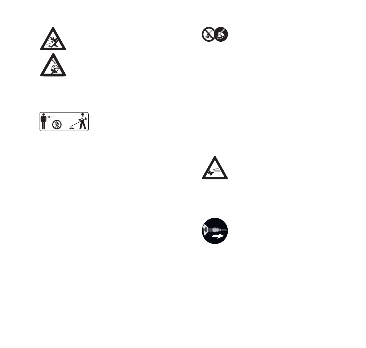
5 INSTRUCCIONES IMPORTANTES DE SEGURIDAD
español / EE.UU
– Revise la zona de trabajo. Retire
piedras, vidrios, rocas, piezas metálicas
y otros objetos que pudieran ser
lanzados por el accesorio de corte,
dañar el accesorio de corte o causar
daños materiales (p. ej., a vehículos
estacionados o ventanas).
– STIHL no recomienda el uso de cuchillas
rígidas cuando se corte en áreas
rocosas o en zonas en las que haya
basura u otros objetos que el accesorio
de corte podría lanzar despedidos.
15m (50ft)
– Lleve siempre una protección
adecuada para los ojos y
asegúrese de no hay nadie a
una distancia de menos de
50 pies (15 m) de la zona de
trabajo. Todas las personas que
deban ingresar al área
restringida también deberán
usar una protección adecuada
para los ojos.
– Para reducir el riesgo de que se produzcan daños
materiales, mantenga esta distancia también con
respecto a vehículos y ventanas.
– Aun así, tenga en cuenta que mantener una
distancia mínima de 50 pies (15 m) no elimina por
completo el riesgo de que se produzcan lesiones
personales y daños materiales causados por objetos
lanzados.
– Apague el motor de inmediato si alguna persona se
le acerca mientras está trabajando con la
motoguadaña / desmalezadora.
■ Su motoguadaña / desmalezadora está equipada con un
deflector. Para reducir el riesgo de que se produzcan
lesiones personales causadas por objetos lanzados y por
contacto con el accesorio de corte:
– Nunca utilice la motoguadaña /
desmalezadora si el deflector está
dañado o no está montado. El accesorio
de corte y el deflector deben formar una
combinación aprobada.
– Mantenga el deflector ajustado
correctamente en todo momento.
■ El uso de alambres, hilos reforzados con metal u otros
accesorios de corte no aprobados no está autorizado y
puede ser extremadamente peligroso.
– Nunca use hilos de metal ni reforzados con metal en
esta motoguadaña / desmalezadora. Emplee solo
los accesorios de corte que se recomiendan en este
manual, y combínelos con el deflector
recomendado. Consulte el capítulo “Combinaciones
de deflectores y accesorios de corte”, @ 25.
■ Para reducir el riesgo de sufrir lesiones graves
provocadas por un arranque accidental de la máquina:
– No toque el accesorio de corte ni la
cabeza segadora con la mano, con los
pies ni con otra parte del cuerpo cuando
la herramienta motorizada esté
conectada a una batería, aunque el
accesorio de corte no esté girando.
Asegúrese de que las personas de los
alrededores se mantienen a un mínimo
de 50 pies (15 m).
– Si el accesorio de corte o el deflector se
ensucian, se obturan o se atoran,
siempre apague el motor, asegúrese de
que el accesorio de corte se ha detenido
y retire el cable de conexión de la
motoguadaña / desmalezadora antes de
revisar el accesorio de corte y el
deflector. Elimine la suciedad, el pasto,
la maleza y otros materiales de la
cabeza segadora o de la cuchilla y del
deflector a intervalos regulares, pero no
olvide desenchufar antes el cable de
conexión.
0458-725-8621-B
79
Page 82

español / EE.UU
5 INSTRUCCIONES IMPORTANTES DE SEGURIDAD
■ Un accesorio de corte dañado o flojo puede vibrar,
agrietarse, romperse o desprenderse durante el
funcionamiento, lo que podría provocar lesiones graves o
mortales.
– Asegúrese de que el accesorio de corte está
correctamente apretado antes de empezar a
trabajar.
– Compruebe el apriete y el estado del accesorio de
corte antes de iniciar los trabajos y siempre que
advierta que el comportamiento de corte cambia
durante el uso. Siempre apague el motor, espere a
que el accesorio de corte se detenga y retire el cable
de conexión antes de revisar la motoguadaña /
desmalezadora, el accesorio de corte o la batería.
– Si el accesorio de corte se afloja después de haberlo
apretado correctamente, interrumpa el trabajo de
inmediato y lleve la máquina a un concesionario de
servicio STIHL autorizado para que la inspeccionen.
■ Un accesorio de corte agrietado, dañado o gastado podría
despedazarse a altas velocidades y causar lesiones
graves o mortales.
– Si una cabeza segadora está agrietada, dañada o
gastada, o si una cuchilla está agrietada, combada,
deformada, dañada, roma o gastada, sustitúyala
inmediatamente, aunque el daño parezca estar
limitado a fisuras superficiales.
– No use nunca una motoguadaña / desmalezadora
que tenga un accesorio de corte flojo o averiado.
PELIGRO
■ Para reducir el riesgo de electrocución:
– Nunca utilice esta motoguadaña cerca
de alambres o de cables que puedan
tener corriente eléctrica.
– No confíe en el aislamiento contra
descargas eléctricas de la
motoguadaña.
5.8 Uso de los accesorios de corte
5.8.1 Contragolpe (empuje de la cuchilla) con accesorios de corte de metal
0000-GXX-3025-A1
ADVERTENCIA
El contragolpe (empuje de la cuchilla) es el
movimiento repentino e incontrolado de la
cabeza segadora hacia el lado derecho del
operador o hacia atrás que puede ocurrir
cuando las zonas sombreadas (en particular las
ilustradas en sombreado oscuro) de una cuchilla
giratoria chocan con un objeto macizo y rígido
tal como un árbol, roca, arbusto o pared. Es
posible que el accesorio de corte salga
despedido hacia la derecha o hacia atrás (flecha
negra) cuando se detenga, se reduzca la
velocidad de la cuchilla, o quede enganchada o
atascada en un objeto que no se corte de
inmediato.
■ Este contragolpe (empuje de la cuchilla) puede ocasionar
la pérdida de control y causarle lesiones graves o
mortales al usuario o a terceros. Para reducir el riesgo, es
necesario extremar las precauciones a la hora de cortar
con la zona sombreada de cualquier cuchilla rígida.
■ A mayor fuerza de contragolpe, mayor dificultad para que
el operador mantenga el control de la máquina. Es muy
probable que se dispare la cuchilla en áreas donde es
difícil ver el material que se está cortando.
80
0458-725-8621-B
Page 83

5 INSTRUCCIONES IMPORTANTES DE SEGURIDAD
0000-GXX-3800-A0
español / EE.UU
■ Son muchos los factores que afectan la producción de
expulsiones, así como su intensidad. Estos incluyen la
velocidad del accesorio de corte, la velocidad a la que el
accesorio de corte entra en contacto con el objeto y el
ángulo de contacto, el estado del accesorio de corte y la
rapidez con la que el accesorio de corte disminuye la
velocidad, queda enganchado o se detiene, entre otros
factores.
– Tenga precaución al trabajar con las zonas
sombreadas de cualquier accesorio de corte
metálico.
■ Para reducir el riesgo de lesiones personales causadas
por las expulsiones y el disparo de la cuchilla al usar un
accesorio de corte rígido:
– Evite cortar cerca de vallas, paredes de un edificio,
troncos de árbol y objetos semejantes cuando se
trabaja con una cuchilla metálica. Para ese tipo de
trabajo, STIHL recomienda el uso de cabezas con
hilo de nilón.
– Mantenga los accesorios de corte metálicos bien
afilados.
– Mantenga a las demás personas a por lo menos 15
m (50 pies) de distancia de la zona de trabajo.
5.8.2 Uso de una cabeza segadora
Las cabezas segadoras solo deben usarse en máquinas
provistas con una cuchilla limitadora del hilo montada en el
deflector a fin de que el hilo tenga la longitud correcta. Al
recortar a lo largo de un vallado, pared o alrededor de los
árboles, es preferible usar una cabeza segadora con hilo de
nilón para reducir el riesgo de disparo o expulsión de la
cuchilla, el daño del accesorio de corte y reducir el daño al
vallado, la pared o los árboles.
ADVERTENCIA
■ Para reducir el riesgo de lesiones graves:
– Nunca use un hilo de alambre o reforzado con metal
ni ningún otro material en lugar del hilo de corte de
nilón recomendado. Es posible que unos pedazos
de alambre se desprendan y se expulsen a gran
velocidad contra el operador o los espectadores.
■ Una cabeza segadora agrietada, dañada o gastada
podría despedazarse a altas velocidades y causar
lesiones graves o mortales.
– Sustituya una cabeza segadora que presente
roturas, daños o desgaste de inmediato, aun si el
daño pareciera estar limitado a fisuras superficiales.
■ Al trabajar cerca de vallados, edificios, troncos de
árboles, u otros objetos similares, tenga en cuenta que
aumenta la posibilidad de que ocurran rebotes.
– Tome la precaución de despejar la zona
de todos los objetos y residuos antes de
recortar a lo largo de vallados o paredes,
cerca de troncos de árboles o de otros
objetos que podrían aumentar la
posibilidad de lesiones causadas por el
rebote de objetos lanzados.
► Al trabajar, mueva la motoguadaña de un lado a otro de
manera controlada, en sentido paralelo con respecto al
suelo delante de usted.
0458-725-8621-B
81
Page 84

español / EE.UU
0000-GXX-3801-A0
0000-GXX-3916-A0
5 INSTRUCCIONES IMPORTANTES DE SEGURIDAD
5.8.3 Uso de una cuchilla para cortar pasto
► Al trabajar con una cuchilla para cortar pasto, mueva la
motoguadaña de un lado a otro de manera controlada, en
sentido paralelo con respecto al suelo delante de usted.
Para reducir el riesgo de un contragolpe, use el lado
izquierdo de la cuchilla.
Todos los tipos de pasto y malezas se pueden cortar con
una cuchilla para cortar pasto.
– La función de la cuchilla de 4 dientes para pasto es la de
cortar pasto y malezas. Tiene 4 cuchillos con filo en los
dos lados, esto es, en las partes delantera y trasera.
Cuando los bordes cortantes en un lado se desafilan, es
posible invertir la cuchilla para usar los bordes cortantes
en el otro lado.
– La cuchilla de 8 dientes para pasto se recomienda para
cortar helechos y vegetación carnosa de tipo similar.
Cuando los filos de un lado se desafilan, es necesario
volver a afilarlos. La cuchilla no pueden invertirse para
utilizar los filos del otro lado.
ADVERTENCIA
■ El uso incorrecto de una cuchilla para cortar pasto puede
causar agrietado, picaduras o roturas. Las piezas de
cuchilla lanzadas pueden causar lesiones graves o
mortales al operador o a terceros. Para reducir el riesgo
de lesiones:
– Evite el contacto con objetos duros y macizos tales
como piedras, vidrio, roas o piezas metálicas.
– Revise la hoja para cortar pasto en intervalos
regulares de corta duración en busca de daños. No
continúe trabajando con una cuchilla para cortar
pasto que esté dañada.
– Vuelva a afilar la cuchilla para cortar pasto como se
describe en el envase o en el folleto de
instrucciones.
– Nunca intente cortar materiales parecidos a la
madera con la cuchilla para cortar pasto.
5.8.4 Uso de una cuchilla para matorrales
82
► Al trabajar con una cuchilla para matorrales, mueva la
motoguadaña de un lado a otro de manera controlada, en
sentido paralelo con respecto al suelo delante de usted.
Para reducir el riesgo de un contragolpe, use el lado
izquierdo de la cuchilla.
La cuchilla para matorrales es adecuada para situaciones
que van desde el corte de pasto enmarañado hasta la
eliminación de malezas, plantas silvestres y matorrales.
0458-725-8621-B
Page 85

6 Mantenimiento, reparación y almacenamiento
español / EE.UU
ADVERTENCIA
■ El uso incorrecto de una cuchilla para matorrales puede
hacer que ésta se rompa, se descascarille o se
despedace. Las piezas de cuchilla lanzadas pueden
causar lesiones graves o mortales al operador o a
terceros. Para reducir el riesgo de lesiones:
– Evite el contacto con objetos duros y macizos tales
como piedras, vidrio, roas o piezas metálicas.
– Inspeccione la cuchilla para matorrales a intervalos
periódicos y cortos en busca de daños. No continúe
trabajando con una cuchilla para matorrales que
esté dañada.
– Vuelva a afilar la cuchilla para matorrales
regularmente como se describe en el envase o en el
folleto de instrucciones.
– Al cortar tallos jóvenes y otros materiales parecidos
a la madera de hasta 2 cm (0,8 pulg) de diámetro,
utilice el lado izquierdo de la cuchilla para evitar
situaciones de "expulsión".
– Nunca intente cortar materiales con contextura de
madera de diámetros superiores, puesto que la
cuchilla para matorrales podría engancharse en el
material y tirar de la máquina hacia delante.
6 Mantenimiento, reparación y
almacenamiento
6.1 Advertencias e instrucciones
ADVERTENCIA
■ No hay reparaciones que el usuario esté autorizado para
efectuar a la herramienta motorizada. Para reducir el
riesgo de incendios, descargas eléctricas u otras lesiones
personales y daños a la propiedad:
– Los usuarios deben efectuar únicamente los
trabajos de mantenimiento y limpieza descritos en
este manual.
– Siga precisamente las instrucciones de limpieza y
mantenimiento dadas en las secciones
correspondientes de este manual de instrucciones.
– Nunca intente reparar un accesorio de corte dañado
o roto. Esto puede causar el desprendimiento de
piezas rotas y producir lesiones graves o mortales.
– Use guantes resistentes y antideslizantes al
manipular accesorios de corte metálicos.
– STIHL recomienda que un concesionario de servicio
STIHL autorizado efectúe todos los trabajos de
reparación o reemplazo.
■ El arranque accidental puede causar lesiones personales
o daños a la propiedad. Para reducir el riesgo de lesiones
personales y daños a la propiedad a causa de un
arranque accidental:
– Desconecte el cordón de conexión antes
de inspeccionar la motoguadaña /
desmalezadora o de realizar alguna
tarea de limpieza, mantenimiento o
reparación. Desconecte el cordón de
conexión antes de almacenar la
herramienta motorizada, y siempre que
no esté en uso.
0458-725-8621-B
83
Page 86

español / EE.UU
7 Seguridad de la batería
■ El uso de componentes no autorizados o no aprobados
por STIHL puede causar lesiones graves o mortales y
daños a la propiedad.
– STIHL recomienda que solo se utilicen repuestos
STIHL idénticos.
■ Para reducir el riesgo de lesiones personales graves
debidas a soltura o daños en accesorio de corte:
– Mantenga las cuchillas afiladas.
– Apriete todas las tuercas, pernos y tornillos después
de haber usado la máquina.
– Nunca repare los accesorios de corte dañados
aplicándoles soldadura, enderezándolos o
modificándoles su forma. Sustituya siempre un
accesorio de corte dañado antes de usarlo.
■ La caja de engranajes está caliente durante el
funcionamiento de la máquina. Para reducir el riesgo de
lesiones por quemadura:
– Espere a que la caja de engranajes se
enfríe antes de inspeccionarla o
lubricarla y antes de cambiar un
accesorio de corte o un deflector. Evite
tocar la caja de engranajes cuando está
caliente luego del funcionamiento.
■ El almacenamiento incorrecto puede permitir el uso no
autorizado o causarle daños a la herramienta motorizada,
y también aumenta el riesgo de incendios, sacudidas
eléctricas y lesiones personales o daños a la propiedad.
– Desconecte el cordón de conexión de la herramienta
motorizada antes de almacenarla.
– Nunca almacene la herramienta motorizada con el
cordón de conexión enchufado.
– Guarde la motoguadaña / desmalezadora en un
lugar seco y bajo llave al que los niños y otras
personas no autorizadas no puedan acceder.
7 Seguridad de la batería
7.1 Advertencias e instrucciones
ADVERTENCIA
■ Lea y respete las medidas de seguridad que figuran en la
batería, así como todas las advertencias e instrucciones
que se adjuntan con ella.
■ El uso de baterías no autorizadas puede causar daños en
la herramienta motorizada y provocar incendios,
explosiones, lesiones personales y daños materiales.
– Utilice únicamente baterías de las gamas AR o AP
de STIHL con esta herramienta motorizada.
■ La utilización de las baterías de las gamas AR o AP de
STIHL con cualquier fin que no sea alimentar las
herramientas motorizadas de STIHL podría ser
extremadamente peligroso.
– Use las baterías de las gamas AR y AP de STIHL
solo para proporcionar alimentación a herramientas
motorizadas de STIHL compatibles.
■ El uso de cargadores no autorizados puede causar daños
en la batería y provocar incendios, explosiones, lesiones
personales y daños materiales.
– Para cargar las baterías de la gama AP de STIHL,
utilice siempre cargadores STIHL AL 101, AL 300 o
AL 500 auténticos.
– Para cargar las baterías de mochila de la gama AR
de STIHL, utilice siempre cargadores AL 300 o
AL 500 de STIHL auténticos.
■ La batería tiene funciones y dispositivos de seguridad
que, de dañarse, pueden provocar que la batería genere
calor, se rompa, pierda líquido, se incendie o explote.
84
0458-725-8621-B
Page 87

7 Seguridad de la batería
español / EE.UU
– Nunca permita que la temperatura de la
batería supere los 212 °F (100 °C).
– Nunca prenda fuego a la batería, ni la
coloque sobre o junto a fuegos, estufas
u otro tipo de objetos que alcances
temperaturas muy altas.
– Nunca use ni cargue una batería que funcione
incorrectamente, que esté dañada, agrietada,
deformada o que pierda líquido.
– Nunca abra, desmonte ni golpee la batería; no la
deje caer ni la exponga a impactos fuertes o a daños
de cualquier otro tipo.
– Nunca exponga la batería a microondas ni a
presiones elevadas.
– Nunca introduzca objetos en las rendijas de
ventilación de la batería.
■ Las temperaturas extremas pueden hacer que la batería
genere calor, se rompa, pierda líquido, se incendie o
explote, lo que podría causar lesiones personales graves
o fatales y daños a la propiedad. La exposición a
temperaturas no incluidas en el rango recomendado
puede contribuir además a acortar la vida útil de la batería
y a empeorar su rendimiento.
– Use y guarde la batería únicamente a
una temperatura ambiente de entre
14 °F y 122 °F (-10 °C y 50 °C).
– Nunca guarde la batería en un lugar
expuesto a la luz solar directa ni dentro
de un vehículo si la temperatura exterior
es elevada.
■ Para reducir el riesgo de que se produzcan lesiones
personales y daños materiales en caso de que la batería
humee, emita un olor inusual o se caliente más de lo
habitual durante el uso, la carga o el almacenamiento:
– Interrumpa el uso o la carga de la batería
inmediatamente. Póngase en contacto con las
autoridades en caso de incendio o explosión.
■ Para reducir el riesgo de que se produzca un cortocircuito,
que podría causar, a su vez, una descarga eléctrica, un
incendio o una explosión:
– Asegúrese de mantener secas las
baterías de mochila AR 900, 1000, 2000,
3000 de STIHL. Protéjalas de la lluvia,
del agua y de otros líquidos. Si llueve o
el grado de humedad es muy elevado,
cubra la batería AR 1000, 2000, 3000 de
STIHL con la funda para lluvia antes de
empezar a trabajar.
– Si una batería de la gama AP o AR L de
STIHL ha estado expuesta a la lluvia
durante el trabajo, sáquela de la
herramienta y déjela secar bajo techo.
Asegúrese de que está completamente
seca antes de cargarla o de usarla.
– Nunca sumerja en agua ni en ningún otro
líquido una batería de STIHL.
– Nunca puentee los terminales de la batería con
alambres ni con otros objetos metálicos.
– Cuando no la esté usando, mantenga la batería
alejada de objetos metálicos (p. ej., presillas para
papel, clavos, monedas, llaves).
– Nunca transporte ni guarde la batería en un
recipiente de metal.
– Guarde la batería bajo techo, en un lugar seco.
– Nunca guarde la batería en entornos húmedos o
corrosivos, ni en condiciones que podrían provocar
corrosión en los componentes metálicos.
0458-725-8621-B
85
Page 88

español / EE.UU
8 Antes de empezar a trabajar
– Proteja la batería de la exposición a productos
corrosivos, como las sustancias químicas utilizadas
en el jardín o las sales descongelantes.
– Proteja la batería de la exposición a líquidos
conductores como el agua salada.
– No intente reparar, abrir ni desmontar la batería. No
contiene ninguna pieza que el usuario pueda reparar
sin ayuda.
■ El líquido que contiene la batería, y que puede
derramarse en determinadas circunstancias, es
potencialmente nocivo y puede provocar irritaciones en
los ojos y en la piel, quemaduras químicas y otras
lesiones graves.
– Evite el contacto con la piel y con los ojos.
– Para recoger el líquido de batería derramado, use
un producto absorbente inerte, como la arena.
– En caso de contacto accidental, limpie
inmediatamente y a fondo la zona afectada con un
jabón suave y agua.
– Si le entra líquido de batería en los ojos: no se los
frote. Aclárese los ojos con agua corriente durante al
menos 15 minutos y acuda al servicio médico más
cercano.
■ Si la batería se prende fuego, puede resultar peligrosa.
Para reducir el riesgo de que se produzcan lesiones
personales graves y daños materiales, en caso de
incendio:
– Evacue la zona. El fuego se puede extender
rápidamente. Manténgase lejos de cualquier vapor
que se genere y respete una distancia de seguridad
suficiente.
– Avise a los bomberos.
– Aunque se puede usar agua para apagar un
incendio de batería, es preferible utilizar un extintor
de incendios de polvo químico multiuso.
– El cuerpo de bomberos le informará sobre la forma
adecuada de deshacerse de una batería incendiada.
8 Antes de empezar a trabajar
8.1 Preparación de la motoguadaña para el funcionamiento
Antes de empezar a trabajar:
► Cargue la batería completamente, @ 9.
► Instale el mango tórico, @ 11.1.
► Monte un deflector aprobado para usarse con el accesorio
de corte que se desea utilizar, @ 11.4.1 y @ 25.
► Instale una cabeza segadora, una cuchilla para pasto o
una cuchilla para matorrales que esté aprobada,
@ 11.5.1 o @ 11.6.1 y @ 25.
► Si usa un accesorio de corte metálico, instale la barra de
defensa, @ 11.3.
► Coloque y ajuste la batería AR, el cinturón para batería o
la batería de mochila STIHL, @ 13.1.
► Ajuste el mango tórico, @ 11.2.
► Compruebe el buen funcionamiento y condición de los
controles, @ 16.1.
9 Carga de la batería
9.1 Preparación del cargador para el funcionamiento
ADVERTENCIA
Lea y aténgase a las precauciones de seguridad dadas en
la batería y en el cargador y todas las advertencias e
instrucciones que acompañan a dichos productos. Para
reducir el riesgo de cortocircuito, que podría provocar una
descarga eléctrica, un incendio y una explosión, asegúrese
de que el cargador y sus componentes estén secos y no
estén dañados; opere el cargador puertas adentro a la
temperatura ambiente adecuada.
86
0458-725-8621-B
Page 89
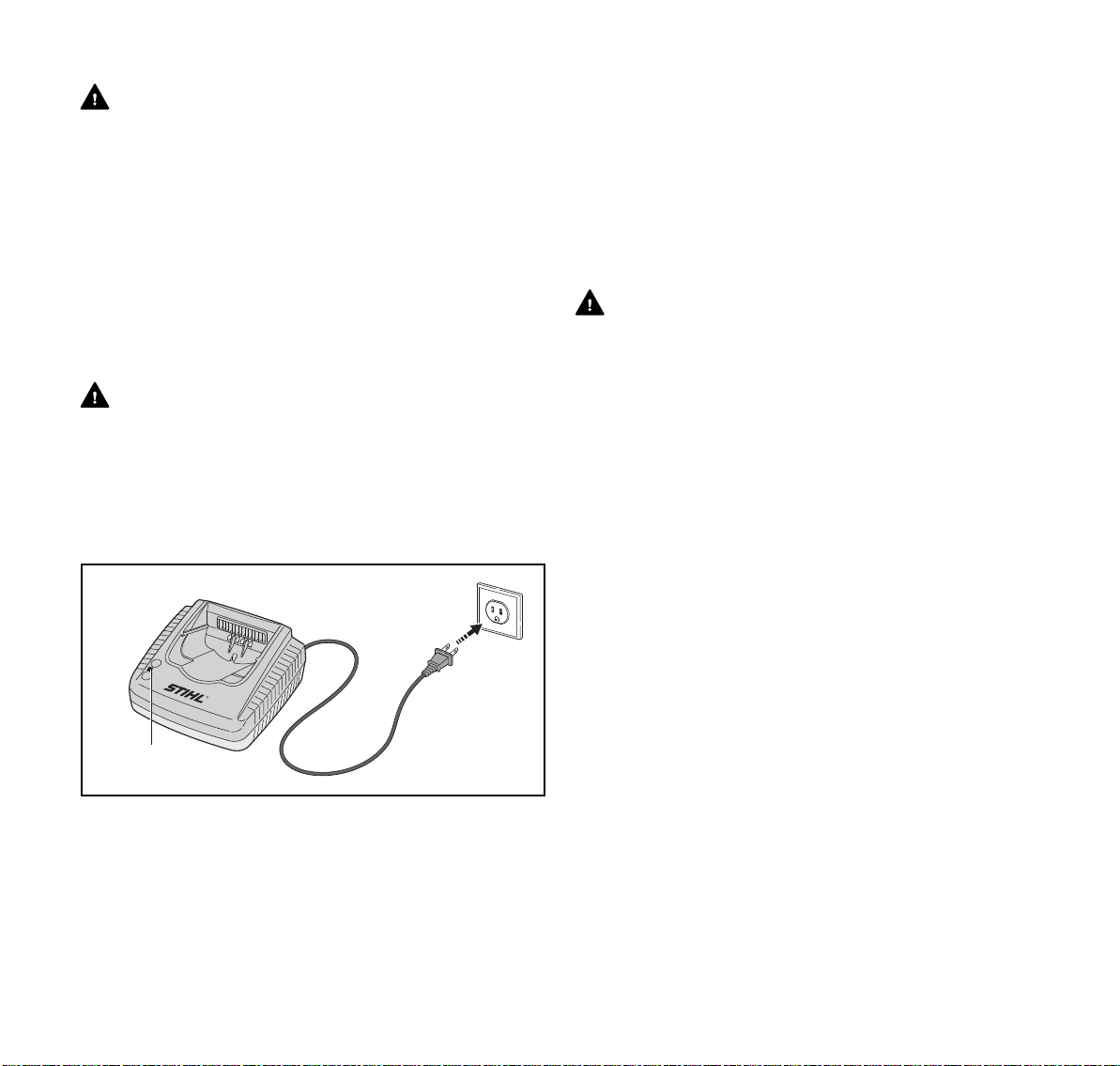
9 Carga de la batería
español / EE.UU
ADVERTENCIA
Un circuito eléctrico doméstico típico suministra entre 15 y
20 amperios. Un cargador STIHL AL 500 consume
aproximadamente 4,8 A. Un cargador AL 300 consume
aproximadamente 4,4 A. Para reducir el riesgo de incendios
causados por la sobrecarga de un circuito eléctrico:
► Compruebe que el circuito eléctrico tenga capacidad
suficiente para suministrar el consumo eléctrico
anticipado antes de cargar la batería.
► Cargue varias baterías una por una, o en circuitos
separados, a menos que se sepa que el circuito es capaz
de soportar el consumo total anticipado de varios
cargadores.
ADVERTENCIA
Dado que el cargador se calienta durante el proceso de
carga, no haga funcionar el cargador sobre superficies que
puedan incendiarse o en un lugar donde haya gases,
líquidos, vapores, polvo u otros materiales y sustancias
combustibles.
Para preparar el cargador para el funcionamiento:
4
3
1
► Conecte el enchufe (3) a un tomacorriente de pared (4)
debidamente instalado que suministre el voltaje y
frecuencia indicados en la chapa de información del
cargador.
El cargador ejecutará una autoprueba inmediatamente
después de enchufarlo. El LED del cargador (1) se iluminará
en verde durante 1 segundo aproximadamente, y luego en
2
rojo por un lapso breve hasta apagarse. Una vez que el LED
se apaga, la autoprueba ha finalizado y el cargador está
listo para cargar la batería.
► Ubique el cordón eléctrico (2) como para que no se lo
pise, cause tropiezos, esté en contacto con objetos
cortantes o partes móviles o, de otro modo sujeto, a daño
o esfuerzo.
9.2 Carga
ADVERTENCIA
Las baterías STIHL tienen características y dispositivos de
seguridad que, de dañarse, pueden provocar que la batería
genere calor, se rompa, pierda líquido, se incendie o
explote. Nunca cargue una batería que funcione mal o que
esté dañada, deformada o tenga fugas, ni utilice un
cargador averiado. Nunca inserte una batería húmeda ni un
adaptador de batería que esté mojado. Nunca use un
cargador que esté mojado. Respete todas las advertencias
e instrucciones específicas de su batería y de su cargador.
La batería no se suministra completamente cargada de
fábrica. STIHL le recomienda que cargue la batería por
completo antes de usarla por primera vez.
Utilice el cargador siempre bajo techo, en habitaciones
secas y a temperaturas ambiente de entre 41 °F y
104 °F (5 °C y 40 °C).
La batería se calienta durante el funcionamiento de la
herramienta motorizada. Si se conecta al cargador una
batería caliente, puede ser necesario esperar a que se
enfríe para que empiece a cargarse. El proceso de carga
solo comienza una vez que la batería se ha enfriado lo
suficiente.
El tiempo de carga depende de varios factores, tales como
0000-GXX-3228-A1
el estado de la batería y la temperatura ambiente. Si quiere
ver una lista completa de los tiempos de carga aproximados,
visite www.stihl.com/charging-times.
0458-725-8621-B
87
Page 90

español / EE.UU
3
2
1
0000-GXX-2680-A0
3
45
1
2
3
4
0000-GXX-3918-A0
10 Diagnóstico por LED y señales acústicas
Para cargar una batería AR:
► Inserte el enchufe del cable de conexión (1) en el
tomacorriente (2) del adaptador AP (3), hasta el tope.
► Inserte el adaptador AP en el cargador (5) hasta que haga
tope.
El LED del cargador (4) se ilumina en verde cuando la
batería se está cargando.
Los LED de la batería AR se iluminan en verde e indican
el estado de carga.
Cuando los LED de la batería se apagan, el proceso de
carga ha finalizado y el cargador se apaga
automáticamente. El adaptador AP se puede retirar del
cargador.
► Desenchufe el cordón eléctrico del tomacorriente cuando
el cargador no esté en uso.
► Cargue las baterías tipo mochila AR de STIHL
únicamente con cargadores de las gamas AL 300 o AL
500 de STIHL auténticos.
Para cargar una batería AP:
► Inserte la batería (2) en el cargador (3) hasta que haga
tope.
El LED del cargador se ilumina en verde cuando la batería
se está cargando.
Los LED (1) de la batería AP se iluminan en verde e
indican el estado de la carga.
Cuando los LED de la batería se apagan, el proceso de
carga ha finalizado y el cargador se apaga
automáticamente. La batería AP se puede retirar del
cargador.
► Desenchufe el cordón eléctrico del tomacorriente cuando
el cargador no esté en uso.
► Para cargar las baterías de la gama AP de STIHL, utilice
siempre cargadores STIHL AL 101, AL 300 o AL 500
auténticos.
10 Diagnóstico por LED y señales
acústicas
10.1 Batería de mochila STIHL AR
10.1.1 Estado de la batería
88
Seis LED y una señal acústica denotan el estado de la
batería.
0458-725-8621-B
Page 91

10 Diagnóstico por LED y señales acústicas
1
2
3
.......
0000-GXX-3229-A1
0000-GXX-2673-A0
100 % 0 %
1 Un pitido breve
La señal acústica funciona como debe hacerlo.
2 Cuatro o seis tonos largos (AR L)
La batería tiene poca carga. Recargue la batería.
3 Sucesión rápida de pitidos breves
Hay una falla en la batería. La señal se detiene
automáticamente al cabo de unos segundos. No intente
cargar, usar ni guardar la batería. Sustituya la batería.
Estos LED pueden encenderse o destellar en verde o rojo.
Si un LED se enciende en rojo continuamente, l a
batería está demasiado caliente o demasiado
fría. Deje que la batería se caliente o se enfríe
gradualmente a una temperatura ambiente de
aproximadamente 10 °C a 20 °C (50 °F a 68 °F).
Si los cuatro LED derechos destellan en rojo y
se escucha una sucesión rápida de pitidos
breves: la batería está averiada y es necesario
reemplazarla. No intente cargar, usar ni guardar
la batería.
► Sea consciente de que su capacidad para oír la señal
acústica puede verse disminuida si usa protectores para
oídos.
Si tres LED se encienden en rojo continuamente, el motor
de la herramienta motorizada está demasiado caliente. Deje
que el motor se enfríe.
Si tres LED destellan en rojo cuando activa el gatillo, la
herramienta motorizada tiene un defecto eléctrico. No utilice
la herramienta motorizada. Solicite a un concesionario de
servicio STIHL autorizado que la revise antes de usarlo.
Para información de localización de averías, @ 23.
10.1.3 Estado de carga
Los LED y señales acústicas en la batería también muestran
el estado de carga de la batería.
Para determinar el estado de carga de la batería:
► Pulse el botón (1) en la batería tipo mochila.
Se escucha un pitido breve. Los LED de la batería se
encenderán o destellarán en verde por unos 5 segundos e
indicarán el estado de carga (vea la ilustración).
Por ejemplo:
Si seis LED se encienden en verde continuamente, la carga
está completa.
Si un LED verde destella y se escuchan cuatro pitidos
largos: resta menos de un 20 % de carga.
español / EE.UU
10.1.2 Estado de la herramienta motorizada
Cuando la batería está conectada con la herramienta
motorizada, los mismos LED en la batería indicarán el
estado de la herramienta motorizada.
0458-725-8621-B
89
Page 92

español / EE.UU
1
0000-GXX-1248-A0
20-40%
40-60%
60-80%
80-100%
0-20%
11 Armado de la motoguadaña / desmalezadora
10.2 Batería AP de STIHL
10.2.1 Estado de la batería Cuatro LED muestran el estado de la batería. Estos LED
pueden encenderse o destellar en verde o rojo.
Si un LED se enciende en rojo continuamente, l a
batería está demasiado caliente o demasiado
fría. Deje que la batería se caliente o se enfríe
gradualmente a una temperatura ambiente de
aproximadamente 10 °C a 20 °C (50 °F a 68 °F).
Si los cuatro LED destellan en rojo: la batería
está averiada y debe reemplazarse. No intente
cargar, usar ni guardar la batería.
10.2.2 Estado de la herramienta motorizada
Los mismos LED en la batería indican el estado de la
herramienta motorizada.
Si tres LED se encienden en rojo continuamente, el motor
de la herramienta motorizada está demasiado caliente. Deje
que el motor se enfríe.
Si tres LED destellan en rojo cuando activa el gatillo, la
herramienta motorizada tiene un defecto eléctrico. No utilice
la herramienta motorizada. Solicite a un concesionario de
servicio STIHL autorizado que la revise antes de usarlo.
Para información de localización de averías, @ 23.
Para determinar el estado de carga de la batería:
► Presione el botón (1) en la batería.
Los LED de la batería se encenderán o destellarán en
verde por unos 5 segundos e indicarán el estado de carga
(vea la ilustración).
Por ejemplo:
Si cuatro LED se encienden en verde continuamente, la
carga está completa.
Si un LED destella en verde, queda menos del 20 % de la
carga.
11 Armado de la motoguadaña /
desmalezadora
10.2.3 Estado de carga
Los LED en la batería también muestran el estado de carga
de la batería.
90
11.1 Montaje del mango tórico
ADVERTENCIA
Para reducir el riesgo de lesionarse por la pérdida de
control, comprobar que el mango tórico esté montado de
manera correcta y segura antes de empezar a trabajar.
Para instalar el mango tórico:
► Apague la herramienta motorizada, @ 15.2.
► Desconecte el cordón de conexión de la motoguadaña,
@ 14.2.
0458-725-8621-B
Page 93

11 Armado de la motoguadaña / desmalezadora
5
0000-GXX-3083-A1
4
6
7
1
2
3
a
1
0000-GXX-3085-A0
2
3
► Coloque un tornillo de fijación (4) en el mango tórico (3).
► Coloque la otra abrazadera (6) contra la parte inferior del
tubo de mando (5) y alinee los agujeros en el mango
tórico y con los de las abrazaderas.
► Coloque las arandelas (2) en los tornillos (1) y pase los
tornillos por los orificios en el mango tórico y los tornillos
de fijación.
► Fije las tuercas cuadradas (7) y atorníllelas bien firmes.
Asegúrese de que el mango esté bien ajustado y que no
se mueva durante el funcionamiento.
11.2 Ajuste del mango tórico
El mango tórico se puede montar de modo que se adapte a
la altura y el alcance del operador.
Para ajustar la posición del mango tórico:
► Apague la herramienta motorizada, @ 15.2.
► Retire el cordón de conexión, @ 14.2.
0458-725-8621-B
español / EE.UU
► Afloje los tornillos (2) y conecte el mango tórico al eje de
la motoguadaña.
► Deslice el mango tórico (1) hasta la posición deseada
sujeto a las siguientes limitaciones:
– Mantenga el espaciador (3) posicionado entre el mango
tórico y la argolla de transporte.
– Si está trabajando con una cabeza segadora, la
distancia marcada con una "a" debe ser de menos de 30
cm (11,8 pulg).
– Si está trabajando con un accesorio de corte metálico,
se debe instalar una barra de defensa y la distancia
marcada con una "a" debe ser de menos de 25 cm (9,8
pulg).
► Apriete los tornillos hasta que el mango tórico esté bien
asegurado y ya no se pueda mover en el tubo de mando.
11.3 Montaje de la barra de defensa
ADVERTENCIA
Para reducir el riesgo de lesiones personales graves
causadas por la pérdida del control o por el contacto con el
accesorio de corte, utilice las cuchillas para pasto y las
cuchillas para matorrales metálicas únicamente cuando la
máquina esté provista de un mango tórico, una barra de
defensa y un arnés.
Para instalar la barra de defensa:
► Apague la herramienta motorizada, @ 15.2.
► Retire el cordón de conexión, @ 14.2.
91
Page 94

español / EE.UU
6
0000-GXX-3082-A0
4
5
7
8
2
3
1
1
2
0000-GXX-3027-A0
► Coloque las tuercas cuadradas (2) en la barra de defensa
(1) y alinee los agujeros.
► Coloque una abrazadera (5) en el mango tórico (3).
► Coloque el otro tornillo de fijación (7) contra el tubo de
mando y alinee los agujeros en el mango tórico y los
tornillos de fijación.
► Coloque la barra de defensa (4) en su posición sobre los
orificios del mango tórico.
► Inserte los tornillos (8) y apriételos bien. Asegúrese de
que la barra de defensa esté bien ajustada y que no se
mueva durante el funcionamiento.
11.4 Instalación y retiro de un deflector
11.4.1 Montaje de un deflector
ADVERTENCIA
Para reducir el riesgo de lesiones causadas por objetos
lanzados y el contacto con el accesorio de corte, nunca use
la motoguadaña / desmalezadora sin tener un deflector
debidamente montado, Mantenga a las demás personas a
no menos de 15 m (50 pies) de distancia. Al usar un
deflector diseñado para usarse con una cuchilla metálica,
debe cambiar el deflector o agregar una faldilla antes de
instalar una cabeza segadora.
11 Armado de la motoguadaña / desmalezadora
ADVERTENCIA
El accesorio de corte y el deflector deben ser una
combinación aprobada. Es extremadamente importante
utilizar únicamente una combinación adecuada de
accesorio de corte y deflector para obtener el desempeño
máximo y reducir el riesgo de lesiones personales causadas
por objetos lanzados o por el contacto con el accesorio de
corte. @ 25.
Los deflectores se instalan en la caja de engranajes de la
misma manera. Para instalar un deflector:
► Apague la herramienta motorizada, @ 15.2.
► Retire el cordón de conexión, @ 14.2.
► Empuje el deflector (1) en las guías de la caja de
engranajes hasta que haga tope. El deflector debe quedar
apretado contra la caja de engranajes.
► Inserte y apriete los tornillos (2). Asegúrese de que el
deflector esté bien ajustado y que no se mueva durante el
funcionamiento.
92
0458-725-8621-B
Page 95

11 Armado de la motoguadaña / desmalezadora
0000-GXX-3029-A0
1
2
español / EE.UU
Para instalar la faldilla y la cuchilla limitadora del hilo:
1
3
4
2
► Inserte el borde guía de la parte inferior del deflector (1)
en la ranura de la faldilla (2).
► Deslice la faldilla hasta que cubra toda la parte inferior del
deflector y haga clic en su lugar.
Cuando la faldilla está correctamente instalada, cubre el
diagrama grabado en el deflector que indica que se
prohíbe el uso con cabezas segadoras.
► Presione la cuchilla limitadora del hilo (3) hacia la ranura
guía en la faldilla.
► Inserte y apriete el tornillo (4) hasta que la cuchilla
limitadora del hilo esté firme en su posición.
11.4.2 Retiro de un deflector
Para retirar un deflector:
► Apague la herramienta motorizada, @ 15.2.
► Retire el cordón de conexión, @ 14.2.
► Saque los tornillos (2).
► Quite el deflector (1)
Para retirar la faldilla del deflector:
0000-GXX-3028-A1
2
1
0000-GXX-3030-A2
► Inserte el pasador de tope (2) en el agujero de la faldilla.
► Deslice la faldilla (1) para quitarla del borde guía de la
parte inferior del deflector.
11.5 Montaje y retiro de una cabeza segadora
11.5.1 Montaje de una cabeza segadora
ADVERTENCIA
El uso de hilo de alambre o reforzado con metal está
prohibido y puede ser extremadamente peligroso. Emplee
solo los accesorios de corte que se recomiendan en este
manual y combínelos con el deflector recomendado,
@ 5.7.4.
0458-725-8621-B
ADVERTENCIA
Un accesorio de corte o una cabeza segadora dañada o
suelta puede vibrar, agrietarse, romperse o salirse de la
motoguadaña / desmalezadora, lo que puede provocar
lesiones graves o mortales o daños a la propiedad.
Asegúrese de que la cabeza segadora y el accesorio de
corte estén bien apretados y en buenas condiciones antes
de empezar a trabajar. @ 5.7.4.
93
Page 96

español / EE.UU
2
3
4
0000-GXX-3031-A0
1
4
1
11 Armado de la motoguadaña / desmalezadora
Cabezas segadoras aparte de la FixCut 31-2
Para instalar una cabeza segadora:
► Apague la herramienta motorizada, @ 15.2.
► Retire el cordón de conexión, @ 14.2.
► Coloque la máquina de modo que esté mirando hacia el
lado inferior del deflector y el tubo de mando esté
orientado hacia arriba.
► Deslice la placa de empuje (2) hacia el eje impulsor (3),
manteniendo el lado de la placa de empuje con el
diámetro más pequeño orientado hacia arriba en
dirección a la cabeza segadora (1).
► Inserte el pasador de tope (4) en el agujero de la caja de
engranajes y gire el tubo de mando hasta que el pasador
de tope se encaje en posición e impida el giro del tubo de
mando.
► Con la mano, atornille la cabeza segadora en sentido
antihorario hacia el eje impulsor manteniendo el pasador
de tope insertado. Para instalar o quitar un accesorio de
corte, es necesario bloquear el eje impulsor con el
pasador de tope.
► Continúe enroscando la cabeza segadora hasta que esté
montada de manera correcta y segura.
► Saque el pasador de tope del agujero de la caja de
engranajes.
Cabeza segadora FixCut 31-2
Para montar la cabeza segadora FixCut 31-2:
► Apague la herramienta motorizada, @ 15.2.
► Retire el cordón de conexión, @ 14.2.
1
2
3
4
5
6
0000-GXX-5065-A0
► Coloque la máquina de modo que esté mirando hacia el
lado inferior del deflector y el tubo de mando esté
orientado hacia arriba.
► Deslice la placa de empuje (4) sobre el tubo de
mando (5), manteniendo el costado de la placa de empuje
que tiene el diámetro pequeño orientado hacia arriba,
hacia la cabeza segadora FixCut 31-2 (3).
► Inserte el pasador de tope (6) en el agujero de la caja de
engranajes y gire el tubo de mando hasta que el pasador
de tope se encaje en posición e impida el giro del tubo de
mando.
94
0458-725-8621-B
Page 97

11 Armado de la motoguadaña / desmalezadora
español / EE.UU
► Coloque la cabeza segadora directamente encima de la
placa de empuje de modo que el collar de la placa de
empuje (4) se enganche en el agujero de montaje de la
cabeza segadora.
► Deslice la arandela de empuje (2) en el tubo de mando.
Mantenga el lardo arqueado orientado hacia arriba y el
lado plano orientado hacia la cabeza segadora FixCut 31-
2.
► Enrosque la tuerca (1) en sentido antihorario y apriétela
hasta que la cabeza segadora quede montada de modo
correcto y seguro.
► Saque el pasador de tope del agujero de la caja de
engranajes.
INDICACIÓN
Si la motoguadaña se usa con un hilo excesivamente largo,
se aumenta la carga del motor y se reduce la velocidad de
funcionamiento. Esto puede causar sobrecalentamiento y
daños a componentes importantes.
INDICACIÓN
Después de instalar o quitar el accesorio de corte, quite
siempre el pasador de tope que se usa para bloquear el eje
impulsor.
11.5.2 Retiro de una cabeza segadora
► Saque el pasador de tope del agujero de la caja de
engranajes.
Cabeza segadora FixCut 31-2
Para retirar la cabeza segadora FixCut 31-2:
► Apague la herramienta motorizada, @ 15.2.
► Retire el cordón de conexión, @ 14.2.
► Utilice el pasador de tope para bloquear el giro del tubo de
mando.
► Coloque la máquina de modo que esté mirando hacia el
lado inferior del deflector y el tubo de mando esté
orientado hacia arriba.
► Destornille la tuerca girándola en sentido horario.
► Quite la arandela de empuje.
► Retire la cabeza segadora.
► Quite la placa de empuje.
► Saque el pasador de tope del agujero de la caja de
engranajes.
11.6 Montaje y retiro de un accesorio de corte
metálico
11.6.1 Montaje de un accesorio de corte metálico
Cabezas segadoras aparte de la FixCut 31-2
Para retirar la cabeza segadora:
► Apague la herramienta motorizada, @ 15.2.
► Retire el cordón de conexión, @ 14.2.
► Utilice el pasador de tope para bloquear el giro del tubo de
mando.
► Coloque la máquina de modo que esté mirando hacia el
lado inferior del deflector y el tubo de mando esté
orientado hacia arriba.
► Destornille la cabeza segadora girándola en sentido
horario.
► Quite la placa de empuje.
0458-725-8621-B
ADVERTENCIA
Las cuchillas para cortar pasto y las cuchillas para cortar
matorrales son filosas. Si entran en contacto con alguna
parte de su cuerpo, le causarán una herida, aunque el
accesorio de corte metálico esté detenido. Use siempre
guantes resistentes al montar o manipular un accesorio de
corte metálico, @ 5.5.
ADVERTENCIA
Un accesorio de corte dañado o suelto puede vibrar,
agrietarse, romperse o salirse de la máquina, lo que puede
provocar lesiones graves o mortales o daños a la propiedad.
Asegúrese de que el accesorio de corte metálico esté bien
apretado y en buenas condiciones antes de empezar a
trabajar. @ 5.7.4.
95
Page 98

español / EE.UU
1
0000-GXX-3032-A1
2
3
4
5
6
7
0000-GXX-3919-A0
A
11 Armado de la motoguadaña / desmalezadora
Para instalar el accesorio de corte metálico:
► Apague la herramienta motorizada, @ 15.2.
► Retire el cordón de conexión, @ 14.2.
► Coloque la máquina de modo que esté mirando hacia el
lado inferior del deflector y el tubo de mando esté
orientado hacia arriba.
► Deslice la placa de empuje (5) sobre el eje impulsor (6).
Sitúese del lado de la placa de empuje con el diámetro
más pequeño hacia arriba.
► Coloque el accesorio de corte (4) directamente sobre la
placa de empuje. Asegúrese de que el accesorio de corte
esté posicionado de manera tal que gire en la dirección
que se indica en el deflector.
► Deslice la placa de empuje (3) sobre el eje impulsor.
Mantenga el lado arqueado hacia arriba y el lado plano
hacia el accesorio de corte metálico.
► Deslice la placa de empuje (2) sobre el eje impulsor.
► Inserte el pasador de tope (7) en el agujero de la caja de
engranajes y gire el accesorio de corte hasta que el
pasador de tope se encaje en posición e impida el giro del
tubo de mando.
► Enrosque la tuerca (1) en sentido antihorario y apriétela
hasta que el accesorio de corte quede montado de modo
correcto y seguro.
► Saque el pasador de tope del agujero de la caja de
engranajes.
Los accesorios de corte con más de 4 filos deben instalarse
con los filos orientados en la dirección de rotación. De lo
contrario, el accesorio no cortará. El sentido de rotación se
indica con una flecha ubicada en la parte interior del
deflector.
INDICACIÓN
Las flechas en el deflector (A) (vista de abajo) muestran el
sentido correcto de rotación del accesorio de corte. Sin
embargo, si se lo observa desde arriba, el accesorio de
corte gira en sentido antihorario.
INDICACIÓN
Después de haber montado o retirado el accesorio de corte,
siempre saque el pasador de tope empleado para bloquear
el giro del tubo de mando.
96
0458-725-8621-B
Page 99

12 Uso de un arnés para batería
español / EE.UU
11.6.2 Retiro de un accesorio de corte metálico
Para retirar el accesorio de corte metálico:
► Apague la herramienta motorizada, @ 15.2.
► Retire el cordón de conexión, @ 14.2.
► Coloque la máquina de modo que esté mirando hacia el
lado inferior del deflector y el tubo de mando esté
orientado hacia arriba.
► Utilice el pasador de tope para bloquear el giro del tubo de
mando.
► Destornille la tuerca girándola en sentido horario.
► Quite la placa de refuerzo, la arandela de empuje, el
accesorio de corte metálico y la placa de empuje.
► Saque el pasador de tope del agujero de la caja de
engranajes.
INDICACIÓN
Después de haber montado o retirado el accesorio de corte,
siempre saque el pasador de tope empleado para bloquear
el giro del tubo de mando.
12 Uso de un arnés para batería
12.1 Batería de mochila STIHL AR
12.1.1 Colocación y ajuste del cordón de conexión
ADVERTENCIA
Para reducir el riesgo de lesionarse por tropezarse con el
cordón de conexión o por la pérdida del control de la
herramienta motorizada, siempre asegure el cordón por las
guías presentes en la mochila y con los cierres de velcro, de
la manera descrita a continuación: Coloque y asegure el
cordón de conexión de modo que no interfiera con las
técnicas de trabajo adecuadas ni con su capacidad de
mantener el control de la herramienta motorizada.
ADVERTENCIA
Coloque el cordón de manera que se impida que entre en
contacto con el accesorio de corte/trabajo o que se
enganche en algún objeto, lo cual podría hacerle perder el
equilibrio o el control de la herramienta motorizada y dar por
resultado lesiones personales graves y daños a la
propiedad.
El cordón de conexión puede asegurarse en posiciones
diferentes y ajustarse según la estatura y el alcance del
operador.
A
1
1
B
1
1
1
1
El cordón de conexión puede pasarse por la guía en la
correa para el hombro (ilustración A) o a lo largo de la placa
trasera (ilustración B). Asegure el cordón de conexión al
bastidor de la mochila y con los cierres de velcro (1).
Siempre asegure el cordón de conexión utilizando la guía o
cierres de velcro hacia el mismo lado del cuerpo en el cual
se sujeta y se controla la herramienta motorizada. No
permita que el cordón de conexión penda delante de su
cuerpo ni a su costado.
0000-GXX-2801-A2
0458-725-8621-B
97
Page 100

español / EE.UU
1
0000-GXX-7803-A0
0000-GXX-2815-A1
3
12 Uso de un arnés para batería
C
D
La longitud del cordón de conexión puede ajustarse por
medio de formar un lazo por la parte superior (Ilust. C) o por
el costado (Ilust. D) de la batería tipo mochila, fijándolo con
cierres de velcro.
12.1.2 Colocación del arnés
ADVERTENCIA
Para reducir el riesgo de lesiones personales en caso de
una emergencia, el operador deberá poder quitarse la
batería de mochila rápidamente. En caso de emergencia,
desabroche y quítese el cinturón y la tira de pecho
rápidamente, antes de dejar caer la batería al suelo.
Para asegurar una colocación adecuada:
► Abroche la tira para el pecho (1) y ajústela de modo que
quede cómoda pero segura por su pecho.
0000-GXX-2803-A1
► Ajuste las tiras del arnés de modo que la almohadilla de
la placa quede firme y segura contra su espalda.
► Pase el extremo del cinturón por dentro del lazo (3).
► Para quitarse el arnés, desabroche las hebillas de soltado
rápido del cinturón y de la tira para el pecho y afloje las
tiras del arnés por medio de levantar los ajustadores
deslizantes.
Para ayudar a reducir el riesgo de lesionarse en caso de
emergencia, practique la apertura rápida del sujetador del
cinturón y de la correa de pecho, el soltado de las correas
de hombro y despojarse de la batería.
INDICACIÓN
Para evitar daños, coloque la batería suavemente en el
suelo cuando esté practicando. No permita que la batería
caiga al suelo ni la lance.
► Colóquese la batería tipo mochila sobre la espalda.
► Abroche y ajuste el cinturón (2) de modo que repose de
manera cómoda pero segura sobre sus caderas.
98
12.2 Batería de mochila STIHL
12.2.1 Montaje de la bolsa de baterías AP con su cordón de
conexión en la mochila
ADVERTENCIA
Para reducir el riesgo de lesionarse por tropezarse o por la
pérdida del control de la herramienta motorizada, siempre
asegure el cordón de conexión con los cierres de velcro en
el sujetador de cable. Coloque y asegure el cordón de
0458-725-8621-B
 Loading...