

Page 1

STIHL FS 360 C
Instruction Manual
Notice d’emploi
Page 2

G Instruction Manual
1 - 51
F Notice d’emploi
52 - 109
Page 3

Contents
English
Guide to Using this Manual 2
Safety Precautions and Working
Techniques 3
Approved Combinations of Cutting
Attachment, Deflector, Limit Stop
and Harness 18
Mounting the Bike Handle 20
Adjusting the Throttle Cable 23
Mounting the Deflector 23
Original Instruction ManualPrinted on chlorine-free paper
Mounting the Cutting Attachment 24
Fuel 28
Fueling 29
Fitting the Full Harness 30
Balancing the Machine 31
Starting / Stopping the Engine 31
Operating Instructions 34
Air filter 34
Engine Management 35
M-Tronic 35
Winter Operation 36
Spark Plug 37
Engine Running Behavior 39
Printing inks contain vegetable oils, paper can be recycled.
Storing the Machine 39
Sharpening Metal Cutting Blades 39
Maintaining the Mowing Head 40
Inspection and Maintenance by
User 41
Inspections and Maintenance by
Dealer 42
Maintenance and Care 44
Main Parts 46
Specifications 48
Maintenance and Repairs 49
Disposal 49
STIHL Limited Emission Control
Warranty Statement 49
Allow only persons who fully understand
this manual to operate your clearing
saw.
To receive maximum performance and
satisfaction from your STIHL clearing
saw, it is important that you read,
understand and follow the safety
precautions and the operating and
maintenance instructions in chapter
"Safety Precautions and Working
Techniques" before using your clearing
saw. For further information you can go
to www.stihlusa.com.
Contact your STIHL dealer or the STIHL
distributor for your area if you do not
understand any of the instructions in this
manual.
WARNING
Because a clearing saw is a high-speed
cutting tool some special safety
precautions must be observed to reduce
the risk of personal injury. Careless or
improper use may cause serious or even
fatal injury.
Make sure your unit is equipped with the
proper deflector, handle and harness for
the type of cutting attachment being
used. Always wear proper eye
protection.
© ANDREAS STIHL AG & Co. KG, 2018
0458-746-8221-D. VA4.L18.
0000007311_006_GB
FS 360 C
This instruction manual is protected by copyright. All rights reserved, especially the rights to reproduce, translate and process
with electronic systems.
1
Page 4

English
Guide to Using this Manual
Pictograms
The meanings of the pictograms
attached to or embossed on the
machine are explained in this manual.
Depending on the model concerned, the
following pictograms may be on your
machine.
Fuel tank for gasoline
and engine oil mixture
Press to operate decompression valve
Manual fuel pump
Press to operate manual
fuel pump
Filler hole for gear
lubricant
Air intake summer mode
Air intake winter mode
Handle heating
Symbols in Text
Many operating and safety instructions
are supported by illustrations.
The individual steps or procedures
described in the manual may be shown
in different ways:
N A bullet indicates a step or
procedure.
A description of a step or procedure that
refers directly to an illustration may
contain item numbers that appear in the
illustration. For example:
N Remove the screw (1)
N Pull the spark arresting screen (2)
upwards out of the muffler
In addition to the operating instructions,
this manual may contain paragraphs
that require your special attention. Such
paragraphs are indicated with the
symbols and signal words described
below:
DANGER
Indicates a hazardous situation that, if
not avoided, will result in death or
serious injury.
WARNING
Indicates a hazardous situation that, if
not avoided, could result in death or
serious injury.
NOTICE
Indicates a risk of property damage,
including damage to the machine or its
individual components.
Engineering Improvements
STIHL’s philosophy is to continually
improve all of its products. As a result,
engineering changes and improvements
are made from time to time. Therefore,
some changes, modifications and
improvements may not be covered in
this manual. If the operating
characteristics or the appearance of
your machine differs from those
described in this manual, please contact
your STIHL dealer or the STIHL
distributor for your area for assistance.
2
FS 360 C
Page 5

English
Safety Precautions and
Working Techniques
Because a clearing saw
is a high-speed, fast-cutting power tool
sometimes equipped with
sharp cutting blades,
special safety precautions must be observed to
reduce the risk of personal injury.
It is important that you
read, fully understand
and observe the following
safety precautions and
warnings. Read the
instruction manual and
the safety precautions
periodically. Careless or
improper use may cause
serious or fatal injury.
The terminology utilized in this manual
when referring to the power tool reflects
the fact that different types of cutting
attachments may be mounted on it. The
term "trimmer" is used to designate an
FS unit that is equipped with a nylon line
head or a head with flexible plastic
blades (i.e., the PolyCut head). A
"brushcutter" designates a unit
equipped with a rigid metal blade. Many
FS models may be used as either a
trimmer or a brushcutter – therefore, the
power tool is referred in this manual as a
"trimmer / brushcutter." Some smaller
and / or lightweight FS models may only
be used as a trimmer, i.e., they may not
be used with metal blades.
The term "clearing saw" indicates a
high-powered trimmer / brushcutter that
is particularly suited for use with a
circular saw blade to clear saplings or
small trees.
WARNING
As more fully explained later in these
Safety Precautions, to reduce the risk of
personal injury, make sure your unit is
equipped with the proper deflector, limit
stop and harness for the type of cutting
attachment you are using. Use only
cutting attachments that are specifically
authorized by STIHL for use on your FS
model.
Have your STIHL dealer show you how
to operate your power tool. Observe all
applicable local safety regulations,
standards and ordinances.
WARNING
Do not lend or rent your power tool
without the instruction manual. Be sure
that anyone using it understands the
information contained in this manual.
WARNING
The use of this machine may be
hazardous. If the rotating line or blade
comes in contact with your body, it will
cut you. When it comes in contact with
solid foreign objects such as rocks or
bits of metal, it may fling them directly or
by ricochet in the direction of bystanders
or the operator. Striking such objects
could damage the cutting attachment
and may cause blades to crack, chip or
break. Thrown objects, including broken
heads or blades, may result in serious or
fatal injury to the operator or bystanders.
STIHL does not recommend the use of
rigid blades when cutting in stony areas.
Use your clearing saw equipped with the
appropriate cutting attachment only for
cutting grass, brush, wood and similar
material.
WARNING
Do not use it for other purposes, since
misuse may result in personal injury or
property damage, including damage to
the machine.
WARNING
Minors should never be allowed to use
this power tool. Bystanders, especially
children, and animals should not be
allowed in the area where it is in use.
WARNING
To reduce the risk of injury to bystanders
and damage to property, never let your
power tool run unattended. When it is
not in use (e.g. during a work break),
shut it off and make sure that
unauthorized persons do not use it.
Most of these safety precautions and
warnings apply to the use of all STIHL
clearing saws. Different models may
have different parts and controls. See
the appropriate section of your
instruction manual for a description of
the controls and the function of the parts
of your model.
Safe use of a clearing saw involves
1. the operator
2. the power tool
3. the use of the power tool.
FS 360 C
3
Page 6

English
THE OPERATOR
Physical Condition
You must be in good physical condition
and mental health and not under the
influence of any substance (drugs,
alcohol, etc.) which might impair vision,
dexterity or judgment. Do not operate
this machine when you are fatigued.
WARNING
Be alert – if you get tired, take a break.
Tiredness may result in loss of control.
Working with any power tool can be
strenuous. If you have any condition that
might be aggravated by strenuous work,
check with your doctor before operating
this machine.
WARNING
Prolonged use of a power tool (or other
machines) exposing the operator to
vibrations may produce whitefinger
disease (Raynaud's phenomenon) or
carpal tunnel syndrome.
These conditions reduce the hand's
ability to feel and regulate temperature,
produce numbness and burning
sensations and may cause nerve and
circulation damage and tissue necrosis.
All factors which contribute to
whitefinger disease are not known, but
cold weather, smoking and diseases or
physical conditions that affect blood
vessels and blood transport, as well as
high vibration levels and long periods of
exposure to vibration are mentioned as
factors in the development of whitefinger
disease. In order to reduce the risk of
whitefinger disease and carpal tunnel
syndrome, please note the following:
– Most STIHL power tools are
available with an anti-vibration
("AV") system designed to reduce
the transmission of vibrations
created by the machine to the
operator's hands. An AV system is
recommended for those persons
using power tools on a regular or
sustained basis.
– Wear gloves and keep your hands
warm.
– Keep the AV system well
maintained. A power tool with loose
components or with damaged or
worn AV elements will tend to have
higher vibration levels.
– Maintain a firm grip at all times, but
do not squeeze the handles with
constant, excessive pressure. Take
frequent breaks.
All the above-mentioned precautions do
not guarantee that you will not sustain
whitefinger disease or carpal tunnel
syndrome. Therefore, continual and
regular users should closely monitor the
condition of their hands and fingers. If
any of the above symptoms appear,
seek medical advice immediately.
WARNING
The ignition system of the STIHL unit
produces an electromagnetic field of a
very low intensity. This field may
interfere with some pacemakers. To
reduce the risk of serious or fatal injury,
persons with a pacemaker should
consult their physician and the
pacemaker manufacturer before
operating this tool.
Proper Clothing
To reduce the risk of injury, the operator
should wear proper protective apparel.
WARNING
The deflector provided with your power
tool will not protect the operator from all
foreign objects (gravel, glass, wire, etc.)
thrown back by the rotating cutting
attachment. Thrown objects may also
ricochet and strike the operator.
4
FS 360 C
Page 7

English
WARNING
To reduce the risk of
injury to your eyes never
operate your power tool
unless wearing goggles
or properly fitted protective glasses with
adequate top and side
protection complying with
ANSI Z87 "+" (or your
applicable national standard). To reduce the risk of
injury to your face STIHL
recommends that you
also wear a face shield or
face screen over your
goggles or protective
glasses.
Wear an approved safety
hard hat to reduce the
risk of injury to your head
when there is a danger of
head injuries.
Power tool noise may
damage your hearing.
Wear sound barriers (ear
plugs or ear mufflers) to
protect your hearing.
Continual and regular
users should have their
hearing checked
regularly.
Be particularly alert and cautious when
wearing hearing protection because
your ability to hear warnings (shouts,
alarms, etc.) is restricted.
Always wear heavy duty
work gloves (e.g. made of
leather or other wear
resistant material) when
handling the machine
and metal blades. Heavyduty, nonslip gloves
improve your grip and
help to protect your
hands.
Clothing must be sturdy
and snug-fitting, but allow
complete freedom of
movement. Wear long
pants made of heavy
material to help protect
your legs. Do not wear
shorts, sandals or go
barefoot.
Avoid loose-fitting jackets, scarfs,
neckties, jewelry, flared or cuffed pants,
unconfined long hair or anything that
could become caught on branches,
brush or the moving parts of the unit.
Secure hair so it is above shoulder level.
Good footing is very
important. Wear sturdy
boots with nonslip soles.
Steel-toed safety boots
are recommended.
THE POWER TOOL
For illustrations and definitions of the
power tool parts see the chapter on
"Main Parts."
WARNING
Never modify this power tool in any way.
Only attachments supplied by STIHL
and expressly approved by STIHL for
use with the specific STIHL model are
authorized. Although certain
unauthorized attachments are useable
with STIHL power tools, their use may,
in fact, be extremely dangerous. For the
cutting attachments authorized by
STIHL for your unit, see the chapter
"Approved Combinations of Cutting
Attachment, Deflector, Limit Stop and
Harness" in the instruction manual or the
STIHL "Cutting Attachments, Parts &
Accessories" catalog.
If this tool is subjected to unusually high
loads for which it was not designed (e.g.
heavy impact or a fall), always check
that it is in good condition before
continuing work. Check in particular that
the fuel system is tight (no leaks) and
that the controls and safety devices are
working properly. Do not continue
operating this machine if it is damaged.
In case of doubt, have it checked by your
STIHL servicing dealer.
THE USE OF THE POWER TOOL
Transporting the Power Tool
WARNING
To reduce the risk of injury from loss of
control and blade or line contact, never
carry or transport your power tool with
the cutting attachment moving.
FS 360 C
5
Page 8

English
002BA479 KN
001BA220 KN
It may be carried only in a horizontal
position. Grip the shaft in a manner that
the machine is balanced horizontally.
Keep the hot muffler away from your
body.
WARNING
To reduce the risk of burn
injury, do not touch hot
parts of the machine and
the gear housing when
they are hot.
WARNING
Always shut off the engine and make
sure the cutting attachment has stopped
before putting a clearing saw down.
When transporting it in a vehicle,
properly secure it to prevent turnover,
fuel spillage and damage to the unit.
STIHL recommends that you keep metal
blades covered with the transport guard
(optional accessory).
Fuel
Your STIHL power tool uses an oil-
gasoline mixture for fuel (see the
chapter on "Fuel" of your instruction
manual).
WARNING
Gasoline is an extremely
flammable fuel. If spilled
and ignited by a spark or
other ignition source, it
can cause fire and serious burn injury or
property damage. Use
extreme caution when
handling gasoline or fuel
mix. Do not smoke or
bring any fire or flame
near the fuel or the power
tool. Note that combustible fuel vapor may
escape from the fuel
system.
Fueling Instructions
WARNING
To reduce the risk of serious injury from
burns, never attempt to refuel the unit
until it has been completely removed
from the operator.
WARNING
Fuel your power tool in well-ventilated
areas, outdoors. Always shut off the
engine and allow it to cool before
refueling. Gasoline vapor pressure may
build up inside the fuel tank depending
on the fuel used, the weather conditions
and the tank venting system.
In order to reduce the risk of burns and
other personal injury from escaping gas
vapor and fumes, remove the fuel filler
cap on your power tool carefully so as to
allow any pressure build-up in the tank
to release slowly. Never remove the fuel
filler cap while the engine is running.
Select bare ground for fueling and move
at least 10 feet (3 m) from the fueling
spot before starting the engine. Wipe off
any spilled fuel before starting your
machine.
WARNING
Check for fuel leakage
while refueling and during
operation. If fuel leakage
is found, do not start or
run the engine until the
leak is fixed and
anyspilled fuel has been
wiped away. Take care
not to get fuel on your
clothing. If this happens,
change your clothing
immediately.
WARNING
In order to reduce the risk of fuel spillage
and fire from an improperly tightened
fuel cap, correctly position and tighten
the fuel cap in the fuel tank opening.
Different models may be equipped with
different fuel caps.
Toolless cap with grip
To do this with this STIHL cap, raise the
grip on the top of the cap until it is upright
at a 90° angle. Insert the cap in the fuel
6
FS 360 C
Page 9

English
001BA227 KN
001BA226 KN
tank opening with the raised positioning
marks on the grip of the cap and on the
fuel tank opening lining up. Using the
grip, press the cap down firmly while
turning it clockwise as far as it will go
(approx. 1/4 turn).
Fold the grip flush with
the top of the cap. Grip
the cap and check for
tightness. If the grip does
not lie completely flush
with the cap and the
detent on the grip does
not fit in the corresponding recess in the filler
opening, or if the cap is
loose in the filler opening,
the cap is not properly
seated and tightened and
you must repeat the
above steps.
Misaligned, damaged or broken cap
N If the cap does not drop fully into the
opening when the positioning marks
line up and/or if the cap does not
tighten properly when twisted, the
base of the cap may be prematurely
rotated (in relation to the top) to the
closed position. Such misalignment
can result from handling, cleaning
or an improper attempt at
tightening.
Left: Base of cap in closed posi-
tion (with open space)
Right: Base of cap correctly posi-
tioned for installation
N To return the cap to the open
position for installation, turn the cap
(with the grip up) until it drops fully
into the tank opening. Next, twist the
cap counterclockwise as far as it will
go (approx. 1/4 turn) – this will twist
the base of the cap into the correct
position. Then, twist the cap
clockwise, closing it normally.
N If your cap still does not tighten
properly, it may be damaged or
broken; immediately stop use of the
unit and take it to your authorized
STIHL dealer for repair.
Screw Cap
WARNING
Unit vibrations can cause
an improperly tightened
fuel filler cap to loosen or
come off and spill quantities of fuel. In order to
reduce the risk of fuel
spillage and fire, tighten
the fuel filler cap by hand
as securely as possible.
See also the "Fueling" chapter in your
Instruction Manual for additional
information.
Before Starting
WARNING
Always check your power tool for proper
condition and operation before starting,
particularly the throttle trigger, throttle
trigger lockout, momentary stop switch,
cutting attachment, deflector and
harness. The throttle trigger must move
freely and always spring back to the idle
position. Never attempt to modify the
controls or safety devices.
WARNING
Check fuel system for leaks, especially
the visible parts, e.g., filler cap, hose
connections, manual fuel pump (only for
power tools equipped with a manual fuel
pump). Do not start the engine if there
are leaks or damage – risk of fire! Have
the machine repaired by a servicing
dealer before using it.
FS 360 C
7
Page 10

English
A
000BA006 KN
B
000BA007 KN
WARNING
Never operate your power tool if it is
damaged, improperly adjusted or
maintained, or not completely or
securely assembled.
WARNING
Do not attach any cutting attachment to
a unit without proper installation of all
required parts. Failure to use the proper
parts may cause the blade or head to fly
off and seriously injure the operator or
bystanders.
WARNING
The cutting attachment must be properly
tightened and in safe operating
condition. Inspect for loose parts (nuts,
screws, etc.) and for cracked or
damaged heads or cracked, bent,
warped or damaged blades. Replace
damaged heads or blades before using
the power tool. Always keep blades
sharp.
Keep the handles clean and dry at all
times; it is particularly important to keep
them free of moisture, pitch, oil, fuel mix,
grease or resin in order for you to
maintain a firm grip and properly control
your power tool.
WARNING
Check that the spark plug boot is
securely mounted on the spark plug – a
loose boot may cause arcing that could
ignite combustible fumes and cause a
fire.
WARNING
To reduce the risk
of personal injury
to the operator
from blade or line
contact and
thrown objects,
make sure your
unit is equipped
with the proper
deflector, limit stop
and harness for
the type of cutting
attachment being
used (see chart in
the chapter on
"Approved Combinations of Cutting
Attachment,
Deflector, Limit
Stop and
Harness").
As can be seen in that chart, some
cutting attachments may require you to
change your deflector, limit stop and / or
harness.
Keep the deflector (and the attached
skirt where appropriate) adjusted
properly at all times (see chapters on
"Mounting the Deflector" and "Mounting
the Cutting Attachment" of your
instruction manual).
Arrows on the deflector (A) and limit
stop (B) (as seen from the underside)
show the correct direction of rotation of
the cutting attachment. When viewed
from above, however, the cutting
attachment rotates counterclockwise.
Some of the following symbols may be
embossed on the outside of the deflector
in order to indicate the approved
combination of cutting attachment and
deflector.
The deflector may be
used in combination with
mowing heads.
The deflector may be
used in combination with
grass cutting blades.
8
FS 360 C
Page 11

English
The deflector may be
used in combination with
brush knives.
The deflector must not be
used in combination with
mowing heads.
The deflector must not be
used in combination with
grass cutting blades.
The deflector must not be
used in combination with
brush knives.
The deflector must not be
used in combination with
circular saw blades.
Adjust carrying harness and hand grip to
suit your size before starting work. The
machine should be properly balanced as
specified in your instruction manual for
proper control and less fatigue in
operation. To be better prepared in case
of an emergency, practice releasing the
unit from the harness as quickly as
possible.
Starting
Start the engine at least 10 feet (3 m)
from the fueling spot, outdoors only.
For specific starting instructions, see the
appropriate section of your manual.
Place the power tool on firm ground or
other solid surface in an open area.
Maintain good balance and secure
footing.
WARNING
To reduce the risk of injury from blade or
line contact, be absolutely sure that the
cutting attachment is clear of you and all
other obstructions and objects, including
the ground, because when the engine
starts at starting-throttle, engine speed
will be fast enough for the clutch to
engage and move the cutting
attachment.
Once the engine has started,
immediately blip the throttle trigger,
which should release the starting throttle
and allow the engine to slow down to
idle.
With the engine running only at idle,
attach the power tool to the spring hook
of your harness (see appropriate
chapter of this manual).
WARNING
Your power tool is a one-person
machine. Do not allow other persons in
the general work area, even when
starting.
WARNING
To reduce the risk of injury from loss of
control, do not attempt to "drop start"
your power tool.
WARNING
When you pull the starter grip, do not
wrap the starter rope around your hand.
Do not let the grip snap back, but guide
the starter rope to rewind it properly.
Failure to follow this procedure may
result in injury to your hand or fingers
and may damage the starter
mechanism.
Important Adjustments
WARNING
To reduce the risk of personal injury
from loss of control or contact with the
running cutting attachment, do not use
your unit with incorrect idle speed. At
correct idle speed, the cutting
attachment should not move.
If your power tool shows an incorrect idle
speed, have your STIHL dealer check
your power tool and make proper
adjustments and repairs.
WARNING
This unit is equipped with an ignition
system that is normally in operational
readiness. After the setting lever is used
to stop the engine, it automatically
springs back to the "on" position. If the
engine is warm, it may be possible to
start it by simply pulling the starter rope,
with no further adjustments. To reduce
the risk of injury, be particularly alert to
keep children away from the unit.
FS 360 C
9
Page 12

English
002BA480 KN
During Operation
Holding and Controlling the Power Tool
Always hold the unit firmly with both
hands on the handles while you are
working. Wrap your fingers and thumbs
around the handles, keeping the
handles cradled between your thumb
and forefinger. Keep your hands in this
position to have your power tool under
control at all times. Make sure your
clearing saw handles and grips are in
good condition and free of moisture,
pitch, oil, fuel mix or grease.
WARNING
Never attempt to operate
your power tool with one
hand. Loss of control of
the power tool resulting in
serious or fatal injury may
result. To reduce the risk
of cut injuries, keep
hands and feet away
from the cutting attachment. Never touch a
moving cutting attachment with your hand or
any other part of your
body.
WARNING
Do not overreach. Keep proper footing
and balance at all times. Special care
must be taken in slippery conditions (wet
ground, snow) and in difficult, overgrown
terrain. Watch for hidden obstacles such
as tree stumps, roots and ditches to
avoid stumbling. For better footing, clear
away scrub and cuttings. Be extremely
cautious when working on slopes or
uneven ground.
WARNING
To reduce the risk of injury from loss of
control, never work on a ladder or on any
other insecure support. Never hold the
cutting attachment above waist height.
Working Conditions
Operate and start your power tool only
outdoors in a well-ventilated area.
Operate it under good visibility and
daylight conditions only. Work carefully.
WARNING
As soon as the engine is
running, this product generates toxic exhaust
fumes containing chemicals, such as unburned
hydrocarbons (including
benzene) and carbon
monoxide, that are
known to cause respiratory problems, cancer,
birth defects, or other
reproductive harm. Some
of the gases (e.g. carbon
monoxide) may be colorless and odorless. To
reduce the risk of serious
or fatal injury / illness
from inhaling toxic fumes,
never run the machine
indoors or in poorly ventilated locations.
WARNING
If the vegetation being cut or the
surrounding ground is coated with a
chemical substance (such as an active
pesticide or herbicide), read and follow
the instructions and warnings that
accompanied the substance at issue.
WARNING
Inhalation of certain dusts, especially
organic dusts such as mold or pollen,
can cause susceptible persons to have
an allergic or asthmatic reaction.
Substantial or repeated inhalation of
dust and other airborne contaminants, in
particular those with a smaller particle
size, may cause respiratory or other
illnesses. Control dust at the source
10
FS 360 C
Page 13

English
15m (50ft)
where possible. Use good work
practices, such as operating the unit so
that the wind or operating process
directs any dust raised by the power tool
away from the operator. Follow the
recommendations of EPA / OSHA /
NIOSH and occupational and trade
associations with respect to dust
("particulate matter"). When the
inhalation of dust cannot be
substantially controlled, i.e., kept at or
near the ambient (background) level, the
operator and any bystanders should
wear a respirator approved by NIOSH /
MSHA for the type of dust encountered.
Operating Instructions
WARNING
Do not operate your power tool using the
starting throttle position, as you do not
have control of the engine speed.
In the event of an emergency, shut off
the engine immediately – move the
momentary stop switch to STOP.
WARNING
The cutting attachment
continues to rotate for a
short period after the
throttle trigger is released
(flywheel effect.)
WARNING
The rotating cutting attachment may
fling foreign objects directly or by
ricochet a great distance.
FS 360 C
To reduce the risk of eye and othe r injury
always wear proper eye protection (see
the chapter on "Proper Clothing") and
ensure that bystanders are at least
50 feet (15 m) away. To reduce the risk
of damage to property, also maintain this
distance from such objects as vehicles
or windows. Even maintaining a
minimum distance of 15 meters cannot
exclude the potential danger. Any
coworkers who must be in the restricted
area should also wear goggles or
protective glasses. Stop the engine
immediately if you are approached.
WARNING
Inspect the work area: To
reduce the risk of injury,
remove stones, pieces of
metal and other solid
objects which could be
thrown 15 meters or more
by the cutting attachment
or damage the cutting
attachment and property
(e.g. parked vehicles,
windows).
WARNING
This clearing saw is normally to be used
at ground level with the cutting
attachment parallel to the ground. Use of
a clearing saw above ground level or
with the cutting attachment
perpendicular to the ground may
increase the risk of injury, since the
cutting attachment is more fully exposed
and the power tool may be more difficult
to control. Never use your clearing saw
as a hedge trimmer.
WARNING
During cutting, check the tightness and
the condition of the cutting attachment at
regular short intervals with the engine
and attachment stopped. If the behavior
of the attachment changes during use,
stop the engine immediately, wait until
the cutting attachment stops, and check
the nut securing the attachment for
tightness and the blade or head for
cracks, wear and damage.
WARNING
A loose blade or head may vibrate,
crack, break or come off the clearing
saw, which may result in serious or fatal
injury. Make sure that the cutting
attachment is properly tightened. Use
the wrench supplied or one of sufficient
length to obtain the proper torque. If the
blade or head loosens after being
properly tightened, stop work
immediately. The retaining nut may be
worn or damaged and should be
replaced. If the blade or head continues
to loosen, see your STIHL dealer. Never
use a clearing saw with a loose cutting
attachment.
WARNING
Replace a cracked, damaged or wornout head or a cracked, bent, warped,
damaged, dull or worn out blade
immediately, even if damage is limited to
11
Page 14

English
superficial cracks. Such attachments
may shatter at high speed and cause
serious or fatal injury.
WARNING
When using rigid blades, avoid cutting
close to fences, sides of buildings, tree
trunks, stones or other such objects that
could cause the power tool to kick out or
could cause damage to the blade.
STIHL recommends use of the nylon line
heads for such jobs. In addition, be alert
to an increased possibility of ricochets in
such situations.
WARNING
If a rotating metal blade strikes a rock or
other hard object, sparks may be
created, which can ignite flammable
materials under certain circumstances.
Flammable materials can include dry
vegetation and brush, particularly when
weather conditions are hot and dry.
When there is a risk of fire or wildfire, do
not use metal blades around flammable
materials or around dry vegetation or
brush. Contact your local fire authorities
or the U.S. Forestry Service if you have
any question about whether vegetation
and weather conditions are suitable for
the use of a metal blade.
WARNING
If the head, blade or deflector becomes
clogged or stuck, always shut off the
engine and make sure the cutting
attachment has stopped before
cleaning. Grass, weeds, etc. should be
cleaned off the blade or from around the
head at regular intervals.
WARNING
To reduce the risk of unintentional
rotation of the cutting attachment and
injury, always shut off the engine and
remove the spark plug boot before
replacing the cutting attachment. To
reduce the risk of injury, always shut off
the engine before adjusting the length of
the nylon line on manually adjustable
mowing heads.
WARNING
Do not turn the engine on over the
starter with the spark plug boot or spark
plug removed since there is otherwise a
risk of fire from uncontained sparking.
WARNING
The gearbox becomes hot during
operation. To reduce the risk of burn
injury, do not touch the gear housing
when it is hot.
WARNING
Never modify your muffler. Any
modification could cause an increase in
heat radiation, sparks or sound level,
thereby increasing the risk of fire, burn
injury or hearing loss. You may also
permanently damage the engine. Have
your muffler serviced and repaired by
your STIHL servicing dealer only.
WARNING
The muffler and other parts of the engine
(e.g. fins of the cylinder, spark plug)
become hot during operation and remain
hot for a while after stopping the engine.
To reduce risk of burns, do not touch the
muffler and other parts while they are
hot. Keep the area around the muffler
clean. Remove excess lubricant and all
debris such as pine needles, branches
or leaves. Let the engine cool down
sitting on concrete, metal, bare ground
or solid wood (away from any
combustible substances.
WARNING
An improperly mounted or damaged
cylinder housing or a
damaged/deformed muffler shell may
interfere with the cooling process of the
muffler. To reduce the risk of fire or burn
injury, do not continue work with a
damaged or improperly mounted
cylinder housing or a
damaged/deformed muffler shell.
Your muffler is furnished with a spark
arresting screen designed to reduce the
risk of fire from the emission of hot
particles. Never operate your unit with a
missing or damaged spark arresting
screen. If your gas/oil mix ratio is correct
(i.e., not too rich), this screen will
normally stay clean as a result of the
heat from the muffler and need no
service or maintenance. If you
experience loss of performance and you
suspect a clogged screen, have your
muffler maintained by a STIHL servicing
dealer. Some state or federal laws or
regulations may require a properly
maintained spark arrestor for certain
uses. See the "Maintenance, Repair and
Storing" section of these Safety
Precautions. Remember that the risk of
a brush or forest fire is greater in hot or
dry conditions.
12
FS 360 C
Page 15

English
002BA354 KN
681BA209 KN
WARNING
Some STIHL power tools
are equipped with a catalytic converter, which is
designed to reduce the
exhaust emissions of the
engine by a chemical process in the muffler. Due
to this process, the muffler does not cool down
as rapidly as conventional mufflers when the
engine returns to idle or
is shut off. To reduce the
risk of fire and burn injuries when using a
catalytic converter,
always set your power
tool down in the upright
position and never locate
it where the muffler is
near dry brush, grass,
wood chips or other combustible materials while it
is still hot.
USING THE CUTTING ATTACHMENT
For an illustration of the various cutting
attachments and instructions on proper
mounting see the chapter on "Mounting
the Cutting Attachment" in your
instruction manual.
WARNING
To reduce the risk of severe or fatal
injury from blade contact and / or loss of
control, never attempt to use a metal
blade on an FS model for which it is not
authorized.
Using the Mowing Heads
Do not use with mowing line longer than
the intended length. With a properly
mounted deflector, the built-in linelimiting blade will automatically adjust
the line to its proper length.
Using the unit with an overly long nylon
cutting line increases the load on the
engine and reduces its operating speed.
This causes the clutch to slip
continuously and results in overheating
and damage to important components
(e.g. clutch, polymer housing
components). Such damage could,
among other things, cause the cutting
attachment to rotate at idle.
Mowing heads are to be used only on
clearing saws equipped with a linelimiting blade in the deflector in order to
keep the line at the proper length (see
"Main Parts" chapter in your instruction
manual).
If the lawn edges are planted with trees
or bordered by a fence etc., it is best to
use a nylon line head. It achieves a
"softer" cut with less risk of damaging
tree bark etc. than polymer blades.
However, the polymer-bladed STIHL
PolyCut produces a better cut if there
are no plants along the edge of the lawn.
Sharpening is not necessary, and worn
polymer blades are easily replaced.
WARNING
To reduce the risk of serious injury,
never use wire or metal-reinforced line
or other material in place of the nylon
cutting lines. Pieces of wire could break
off and be thrown at high speed toward
the operator or bystanders.
STIHL SuperCut mowing head
Fresh line is advanced automatically.
Frayed line is replaced by a simple
adjustment (see instruction sheet
supplied with mowing head).
STIHL AutoCut mowing head
Nylon cutting line advances
automatically when tapped against the
ground (TapAction).
STIHL TrimCut mowing head
Frayed line is replaced by a simple
adjustment (see instruction sheet
supplied with mowing head).
STIHL DuroCut mowing head
Uses only nylon lines.
Observe wear indicators.
NOTICE
There are four wear limit indicators
shaped like exclamation marks in the
base of the DuroCut. If one of these
FS 360 C
13
Page 16

English
002BA396 KN
002BA135 KN
002BA355 KN
built-in indicators becomes visible, do
not continue using the DuroCut since it
might otherwise be damaged. Replace
the worn base plate with a new base
plate. It is important to follow the
maintenance instructions supplied with
the head.
STIHL PolyCut mowing head
Uses either nylon lines or nonrigid,
pivoting polymer blades.
Observe wear indicators.
WARNING
Three rectangular wear limit marks are
applied to the base (periphery) of the
PolyCut. To reduce the risk of serious
injury from breakage of the head or
blades, the PolyCut must not be used
when it has worn as far as one of these
marks. It is important to follow the
maintenance instructions supplied with
the head.
WARNING
If the wear limit marks are ignored, there
is a risk of the cutting attachment
shattering and flying parts injuring the
operator or bystanders. To reduce the
risk of accidents from shattered blades,
avoid contact with stones, metal and
similar solid objects. Check PolyCut
blades for cracks at regular intervals. If a
crack is found on one blade, always
replace all blades.
Risk of Kickout (Blade Thrust) with all
Rigid Cutting Blades
WARNING
Kickout (blade thrust) is
the sudden and uncontrolled motion towards
the operator's right or
rear that can occur when
the shaded area (especially the darkly shaded
area) of a rotating blade
comes in contact with a
solid rigid object like a
tree, rock, bush or wall.
The rapid counterclockwise rotation of the blade
may be stopped or
slowed, and the cutting
attachment may be
thrown to the right or to
the rear.
This kickout (blade thrust) may cause
loss of control of the power tool and may
result in serious or fatal injury to the
operator or bystanders. To reduce the
risk of injury, extreme caution should be
used when cutting with the shaded area
of any rigid blade.
Using the Grass Cutting Blade
All kinds of grass and weeds can be
easily cut with the grass cutting blade.
The power tool is swept in an arc similar
to a scythe.
WARNING
To reduce the risk of serious or fatal
injury from blade breakage, never
attempt to use this blade to cut woody
materials.
The 4-tooth grass cutting blade is
intended to cut grass and weeds. It has
4 cutting knives with cutting edges on
both sides, i.e. front and rear. When the
cutting edges on one side become dull,
the blade can be turned over to utilize
the cutting edges on the other side.
The 8-tooth grass cutting blade is
recommended for cutting fern or reed.
Both types of grass cutting blade have to
be resharpened when all cutting edges
are dull.
Using the Brush Knife
When fitted to the power tool, the brush
knife is suitable for applications ranging
from cutting matted grass to clearing
weeds, wild growth and scrub.
14
FS 360 C
Page 17

English
002BA509 KN
002BA067 KN
To cut wild growth and scrub, lower the
rotating brush knife down onto the
growth to achieve a chopping effect –
but keep the tool below waist height at
all times.
WARNING
Exercise extreme caution when using
this method of cutting. The higher the
cutting attachment is off the ground, the
greater the risk of loss of control and of
cuttings being thrown sideways.
Use the power tool like a scythe to cut
grass, i.e. sweep it to and fro in an arc.
WARNING
When cutting woody materials, use the
left side of the blade to avoid "kickout"
(blade thrust) situations.
WARNING
When cutting young saplings or other
woody materials up to 2 cm (3/4 in.) in
diameter, use the left side of the blade to
avoid "kickout" situations (see section
on "Risk of kickout (blade thrust) with all
rigid cutting blades"). Do not attempt to
cut woody material with a larger
diameter, since the blade may catch or
jerk the power tool forward. This may
cause damage to the blade or power tool
or loss of control of the power tool,
resulting in personal injury. Use a
circular saw blade for such work.
WARNING
Inspect the brush knife at regular short
intervals for signs of damage. Do not
continue working with a damaged brush
knife. Resharpen the brush knife
regularly (when it has dulled noticeably).
Using the Circular Saw Blade
control of the power tool and result in
serious injury. Use a chain saw for such
work.
WARNING
To reduce the risk that the blade will
crack and / or break, avoid all contact
with stones, rocks or the ground.
Sharpen blades in a timely manner as
specified – dull teeth may cause the
blade to crack or shatter.
When a clearing saw with a circular saw
blade is used to cut down small trees,
STIHL recommends that the standard
deflector be removed and replaced by
the special limit stop deflector (see
chapter on "Mounting the Deflector").
This limit stop helps to keep the unit
positioned against the tree during the
cutting process. Inexperienced users
should place the left side of the stop
against the tree trunk before beginning
to cut. This will keep the clearing saw
against the tree during the cutting
operation and will reduce the risk of loss
of control and possible kickout
(described above and briefly again
below).
WARNING
Improper use of a brush knife may cause
it to crack, chip or shatter. Thrown blade
fragments may seriously or fatally injure
the operator or bystanders. To reduce
the risk of injury, avoid contact with hard
or solid foreign objects such as stones,
rocks or pieces of metal.
FS 360 C
Circular saw blades are suitable for
thinning brush and cutting small trees up
to a diameter of 7 cm (2 3/4 in.). Do not
attempt to cut trees with larger
diameters, since the blade may catch or
jerk the clearing saw forward. This may
cause damage to the blade or loss of
002BA214 ST
Before starting the cut, accelerate the
engine up to full throttle. Perform cut
with uniform pressure. STIHL
recommends that the circular saw blade
15
Page 18

English
002BA068 KN
be applied to the right of the tree, using
the non-shaded area of the blade, as
shown in the illustration above.
WARNING
The risk of kickout is highest when
cutting in the darker shaded area. To
reduce the risk of kickout and resulting
injury, do not use this area of the circular
saw blade for cutting trees or shrubs.
Special techniques using the lighter
shaded areas of the blade to cut shrubs
and trees should only be used by
experienced operators with specialized
training in the use and control of the
clearing saw.
When felling small trees, maintain a
distance of at least two tree lengths from
the nearest coworker.
WARNING
In order to reduce the risk of injury from
thrown objects or operator contact with
the blade or head, be sure to remount
the standard deflector when no longer
using a circular saw blade.
MAINTENANCE, REPAIR AND
STORING
Maintenance, replacement, or repair of
the emission control devices and
systems may be performed by any
nonroad engine repair establishment or
individual. However, if you make a
warranty claim for a component which
has not been serviced or maintained
properly or if nonapproved replacement
parts were used, STIHL may deny
coverage.
WARNING
Use only identical STIHL replacement
parts for maintenance and repair. Use of
non-STIHL parts may cause serious or
fatal injury.
Strictly follow the maintenance and
repair instructions in the appropriate
sections of your instruction manual.
WARNING
Always stop the engine and make sure
that the cutting attachment is stopped
before doing any maintenance or repair
work or cleaning the power tool. Do not
attempt any maintenance or repair work
not described in your instruction manual.
Have such work performed by your
STIHL servicing dealer only.
Wear gloves when handling or
performing maintenance on blades.
WARNING
Use the specified spark plug, and make
sure it and the ignition lead are always
clean and in good condition. Always
press the spark plug boot snugly onto
the spark plug terminal of the proper
size. (Note: If the terminal has a
detachable SAE adapter nut, it must be
securely attached.) A loose connection
between the spark plug and the ignition
wire connector in the boot may create
arcing that could ignite combustible
fumes and cause a fire.
WARNING
Never test the ignition system with the
spark plug boot removed from the spark
plug or with a removed spark plug, since
uncontained sparking may cause a fire.
WARNING
Do not operate your power tool if the
muffler is damaged, missing or modified.
An improperly maintained muffler will
increase the risk of fire and hearing loss.
Your muffler is equipped with a sparkarresting screen to reduce the risk of
fire; never operate your power tool if the
screen is missing, damaged or clogged.
Remember that the risk of a brush or
forest fire is greater in hot or dry
weather.
In California, it is a violation of § 4442 or
§ 4443 of the Public Resources Code to
use or operate gasoline-powered tools
on forest-covered, brush-covered or
grass-covered land unless the engine’s
exhaust system is equipped with a
complying spark arrester that is
maintained in effective working order.
The owner/operator of this product is
responsible for properly maintaining the
spark arrester. Other states or
governmental entities/agencies, such as
the U.S. Forest Service, may have
similar requirements. Contact your local
16
FS 360 C
Page 19

fire agency or forest service for the laws
or regulations relating to fire protection
requirements.
WARNING
Never repair damaged cutting
attachments by welding, straightening or
modifying the shape. This may cause
parts of the cutting attachment to come
off and result in serious or fatal injuries.
Keep blades sharp. Tighten all nuts,
bolts and screws after each use.
Do not clean your machine with a
pressure washer. The solid jet of water
may damage parts of the machine.
Store the power tool in a dry and high or
locked location out of reach of children.
Before storing for longer than a few
days, always empty the fuel tank. See
chapter "Storing the Machine" in the
instruction manual.
English
FS 360 C
17
Page 20

English
10
12
13
14
11
18
17
0000-GXX-1184-A1
1
6
15
16
19
4
2
7
8
3
5
9
Approved Combinations of Cutting Attachment, Deflector, Limit Stop and Harness
Cutting Attachment Deflector, Limit Stop Harness
18
FS 360 C
Page 21

English
Approved Combinations
Select correct combination from the
table according to the cutting
attachment you intend to use.
WARNING
For safety reasons only the cutting
attachments and deflectors or limit stops
shown in each row of the table may be
used together. No other combinations
are permitted because of the risk of
accidents.
Cutting Attachments
Mowing heads
1 STIHL AutoCut 40-2
2 STIHL AutoCut 40-4
3 STIHL AutoCut 46-2
4 STIHL TrimCut 41-2
5 STIHL DuroCut 40-4
6 STIHL PolyCut 41-3
12 Scratcher tooth circular saw blade
225
(225 mm dia.)
13 Chisel tooth circular saw blade 225
(225 mm dia.)
14 Carbide tipped circular saw blade
225
(225 mm dia.)
WARNING
Non-metal grass cutting blades, brush
knives, shredder blades and circular
saw blades are not approved.
Deflectors, Limit Stops
15 Deflector for mowing heads
16 Deflector for metal cutting
attachments
17 Limit stop for circular saw blades
18 Limit stop for circular saw blades
Harness
Use grass cutting metal blades, brush
knifes and circular saw blades on this
unit only if equipped with a bike handle.
Do not use rigid polymer blades on this
unit.
Metal cutting attachments
7 Grass cutting blade 230-4
(230 mm dia.)
8 Grass cutting blade 255-8
(255 mm dia.)
9 Brush knife 300-3
(300 mm dia.)
10 Scratcher tooth circular saw blade
200
(200 mm dia.)
11 Chisel tooth circular saw blade 200-
22 (4119), chisel tooth circular saw
blade 200-22 HP (4000)
FS 360 C
19 Full harness must be used
WARNING
Based on the cutting attachment being
used:
Choose the proper deflector in order to
reduce the risk of injury from thrown
objects and contact with the cutting
attachment.
Make sure your unit is equipped with the
proper handle and harness in order to
reduce the risk of injury from loss of
control and contact with the cutting
attachment.
19
Page 22

English
1
3BA003 KN
3BA004 KN
4
2
3BA005 KN
5
7
3BA006 KN
2
4
8
3BA007 KN
Mounting the Bike Handle
Mounting Bike Handle with Swivelling
Handle Support
Do not rotate the control handle (1)
between unpacking and mounting it on
the handlebar; see also chapter on
"Adjusting the Throttle Cable".
Mounting the Handlebar
To assemble the swivelling handle
support it is necessary to fit a spring in
the clamps and secure them to the
handle support on the machine.
N Use the spring (5) from the parts kit
supplied with the machine.
N Push the spring (5) into the lower
clamp molding (6).
N Position the clamp moldings (4) with
handlebar (2) on the handle
support (7).
N Do notrotate the handlebar in the
clamp moldings.
The machine is shipped with the clamp
moldings (4) mounted on the
handlebar (2).
N Do not change the position of the
clamp moldings on the handlebar
until the control handle is mounted.
20
N Raise the grip of the wing screw (8)
to the upright position.
FS 360 C
Page 23

English
5
8
3BA008 KN
7
6
10
7
9
3BA0009 KN
7
6
3BA010 KN
3BA026 KN
11
12
1
002BA451 KN
1
3BA011 KN
3BA012 KN
1
13
13
14
14
2
1
002BA458 KN
11
12
1
002BA459 KN
N Position wing screw (8) in threaded
insert in handle support (7) –
against pressure of spring (5).
N Position the clamp moldings so that
the tabs (9) on the lower clamp
molding (6) line up with the
slots (10) in the handle support (7).
N Rotate wing screw clockwise until
the lower clamp molding (6) butts
against the handle support (7).
N Only tighten the wing screw
moderately.
FS 360 C
N Fold the grip of the wing screw down
so that it is flush.
Mounting the Control Handle
N Take out the screw (11) and remove
the nut (12) from the control
handle (1).
N Pass the control handle (1) under
the drive tube and put it down on the
right-hand side of the machine.
N Swing the control handle (1) behind
the handlebar so that the throttle
trigger (13) is facing up.
N Push the control handle (1) in this
position onto the end of the
handlebar (2) until the holes (14)
are in alignment – the throttle
trigger (13) points up.
N Fit the nut (12) in the control
handle (1), insert the screw (11)
and tighten it down firmly.
21
Page 24

English
3BA027 KN
3BA028 KN
6BA007 KN
3BA014 KN
2
A
6BA005 KN
6BA006 KN
Adjusting the Handlebar
Opening the wing screw
N Fold the grip of the wing screw down
so that it is flush.
N Raise the grip of the wing screw to
the upright position.
N Turn the wing screw
counterclockwise until the handle
support can be moved.
Line up the handlebar
N Move the handlebar to the required
position.
Checking the Throttle Cable
N After mounting the control handle,
check the throttle cable – see
chapter on "Adjusting the Throttle
Cable".
N Position the handlebar (2) so that
distance A is about 17 cm (7 in).
Do not clamp the curved part of the
handlebar.
Closing the wing screw
N Rotate the wing screw clockwise
until it becomes difficult to turn.
N Tighten down the wing screw firmly.
22
FS 360 C
Page 25

English
3BA025 KN
2
8
002BA655 KN
1
002BA401 KN
2
002BA402 KN
Swiveling the Handlebar
Transport position
N Loosen the wing screw (8) and
unscrew it until the handlebar (2)
can be turned clockwise.
N Turn the handlebar 90° and then
swing the handles down.
N Tighten down the wing screw (8)
firmly.
Working position
N Reverse the sequence described
above to swing the handles up and
turn the handlebar
counterclockwise.
Adjusting the Throttle Cable
It may be necessary to correct the
adjustment of the throttle cable after
assembling the machine or after a
prolonged period of operation.
Adjust the throttle cable only when the
unit is completely and properly
assembled.
N Set the throttle trigger to the full
throttle position.
N Carefully rotate the screw in the
throttle trigger in the direction of the
arrow until you feel initial resistance.
Then rotate it another half turn in the
same direction.
Mounting the Deflector
Use the Right Deflector
WARNING
Deflector (1) is approved for mowing
heads only and must therefore be
mounted before fitting a mowing head.
WARNING
Deflector (2) is approved for grass
cutting blades and brush knives only and
must therefore be mounted before fitting
a grass cutting blade or brush knife.
FS 360 C
23
Page 26

English
3
002BA433 KN
4
6
5
002BA434 KN
002BA406 KN
002BA490 KN
2
1
3
5
002BA491 KN
4
2
WARNING
The limit stop (3) is approved as a
deflector for circular saw blades only
and must therefore be mounted before
fitting a circular saw blade. It is also
necessary to change the guard ring (5),
see "Mounting the Cutting Attachment" /
"Mounting Circular Saw Blades".
Mounting the Deflector
Deflectors (1 to 3) are mounted to the
gearbox in the same way.
N Remove dirt from joints on gearbox
and defelector – make sure that no
dirt gets into the screw holes in the
gearbox.
N Place the deflector on the gearbox
(5).
N Insert the screws (6) and tighten
them down firmly.
24
Mounting the Cutting
Attachment
Placing power tool on the ground
N Shut off the engine.
N Lay your power tool on its back so
that the cutting attachment
mounting face is pointing up.
Use the Right Guard Ring
Your power tool comes standard with a
guard ring.
The guard ring is also available as a
special accessory.
The guard ring must be mounted with
particular care. Have this work
performed by your servicing dealer.
STIHL recommends a STIHL servicing
dealer.
Guard ring for mowing applications
Always fit guard ring (1) when using
– mowing heads
– grass cutting blades
– brush knives
– shredder blades
to ensure optimum protection against
grass cuttings.
Guard ring for sawing applications
Fit guard ring (4) only when you use
circular saw blades.
FS 360 C
Page 27

English
002BA407 KN
1
2
3
4
1
2
1
681BA196 KN
2
002BA407 KN
1
2
3
4
2
3
1
0812BA021 KN
2
Mounting the Thrust Plate and Guard
Washer
N Fit the thrust plate (1) and guard
washer (2) on the shaft (3).
NOTICE
The thrust plate (1) on the gearbox is
necessary for mounting all cutting
attachments.
NOTICE
The guard washer (2) is required for
mounting
– mowing heads
– grass cutting blades
– brush knives
– shredder blades
to the gearbox. The guard washer is not
required for mounting circular saw
blades.
Checking the Thrust Plate
The thrust plate consists of the thrust
plate body (1) to which a captive guard
washer (2) is fitted.
WARNING
Never use a thrust plate without the
guard washer. Always replace a thrust
plate if the guard washer is missing.
Cleaning Gearbox Mounting Hardware
for Cutting Attachment
NOTICE
Check inside of guard ring (4) and area
around it for dirt at regular intervals, or
when you change the cutting
attachment, and clean if necessary as
follows:
N Pull the guard washer (1) and thrust
plate (2) off the shaft.
N Thoroughly clean the guard ring,
shaft, thrust plate and guard washer
– do not remove the guard ring.
Blocking the Shaft
The output shaft (1) must be blocked
with the stop pin (2) to mount or remove
cutting attachments. The stop pin is
included with the machine and is
available as a special accessory.
N Insert the stop pin (2) in the bore (3)
in the gearbox as far as stop, apply
slight pressure.
N Rotate shaft or cutting attachment
until the stop pin slips into position
and blocks the shaft.
Mounting the Cutting Attachment
WARNING
Use a deflector that matches the cutting
attachment – see "Mounting the
Deflector".
FS 360 C
25
Page 28

English
1
002BA385 KN
0000-GXX-0421-A0
1 2
3
4
Fitting Mowing Head with Screw
Mounting
Keep the instruction leaflet for the
mowing head in a safe place.
N Screw the mowing head
counterclockwise on to the shaft (1)
as far as stop.
N Block the shaft.
N Tighten down the mowing head
firmly.
Removing and Installing Metal Cutting
Attachments
Keep the leaflet and packaging of the
metal cutting attachment in a safe place.
WARNING
Wear protective gloves to reduce the
risk of direct contact with the sharp
cutting edges.
Mount only one metal cutting
attachment.
Mounting Grass Cutting Blades, Brush
Knife
Notice on new machines that come
standard with a mowing head only: A
"metal mowing attachment mounting kit"
is required to mount a grass cutting
blade or brush knife. Kits are available
from your servicing dealer.
Check direction of rotation of cutting
attachment
The cutting edges of the cutting
attachments 1 and 2 must point
clockwise.
Cutting attachments 3 and 4 may be
mounted either way round – they must
be turned over regularly to help avoid
one-sided wear.
N Use guard ring for mowing
attachments.
NOTICE
Remove the tool used to block the shaft.
Removing the Mowing Head
N Block the shaft.
N Unscrew the mowing head
26
clockwise.
FS 360 C
Page 29

N Place the cutting attachment (1) in
2
3
1
4
002BA409 KN
b
a
002BA490 KN
2
1
3
5
002BA491 KN
4
2
position.
WARNING
Collar (a) must locate in the cutting
attachment's mounting hole (b).
Securing the cutting attachment
N Fit the thrust washer (2) – convex
side must face up.
N Fit the rider plate (3).
N Block the shaft.
N Fit the nut (4) counterclockwise and
If the mounting nut has become too
loose, fit a new one.
tighten it down firmly.
WARNING
NOTICE
Remove the tool used to block the shaft.
Removing the cutting attachment
N Block the shaft.
N Unscrew the nut clockwise.
N Pull the cutting attachment with its
mounting hardware off the gearbox.
Mounting Circular Saw Blades
A limit stop kit, which includes a limit
stop and a guard ring for circular saw
blades, is available as a special
accessory for mounting circular saw
blades.
Notice on new machines that come
standard with a mowing head only:
Further mounting hardware is necessary
for a circular saw blade. It is available
from your servicing dealer.
Change the guard ring.
Recommendation: The guard ring must
be mounted with particular care. Have
this work performed by your servicing
dealer. STIHL recommends a STIHL
servicing dealer.
English
N Remove the guard washer (1) and
thrust plate (2).
N Remove the guard ring (3) for
mowing attachments.
N Keep the guard washer and guard
ring in a safe place for future use.
N Fit the guard ring (4) for saw blades.
N Slip the thrust plate (2) over the
shaft.
N Fit the limit stop (5) for circular saw
blades.
NOTICE
Do not use the guard washer (1) with
circular saw blades.
FS 360 C
27
Page 30

English
681BA165 KN
2
3
1
4
002BA423 KN
b
a
Check direction of rotation of cutting
attachment
Cutting edges of circular saw blades
must point clockwise.
N Place the cutting attachment (1) in
Collar (a) must locate in the cutting
attachment's mounting hole (b).
position.
WARNING
Securing the cutting attachment
N Fit the thrust washer (2) – convex
side must face up.
N Fit the rider plate (3).
A rider plate (3) for sawing applications
is available as a special accessory. It
allows the full depth of cut of the saw
blade to be used.
N Block the shaft.
N Fit the nut (4) counterclockwise and
tighten it down firmly.
WARNING
If the mounting nut has become too
loose, fit a new one.
NOTICE
Remove the tool used to block the shaft.
Removing the cutting attachment
N Block the shaft.
N Unscrew the mounting nut
clockwise.
N Pull the cutting attachment with its
mounting hardware off the gearbox.
Fuel
This engine is certified to operate on
unleaded gasoline and STIHL twostroke engine oil at a mix ratio of 50:1.
Your engine requires a mixture of highquality gasoline and two-stroke air
cooled engine oil.
Use mid-grade unleaded gasoline with a
minimum octane rating of 89 (R+M/2)
and no more than 10% ethanol content.
Fuel with a lower octane rating may
increase engine temperatures. This, in
turn, increases the risk of piston seizure
and damage to the engine.
The chemical composition of the fuel is
also important. Some fuel additives not
only detrimentally affect elastomers
(carburetor diaphragms, oil seals, fuel
lines, etc.), but magnesium castings and
catalytic converters as well. This could
cause running problems or even
damage the engine. For this reason
STIHL recommends that you use only
high-quality unleaded gasoline!
For further details, see
www.STIHLusa.com/ethanol
Use only STIHL two-stroke engine oil or
equivalent high-quality two-stroke
engine oils that are designed for use
only in air cooled two-cycle engines.
To ensure the maximum performance of
your STIHL engine, use a high quality 2cycle engine oil. To help your engine run
cleaner and reduce harmful carbon
deposits, STIHL recommends using
STIHL HP Ultra 2-cycle engine oil or ask
your dealer for an equivalent fully
synthetic 2-cycle engine oil.
28
FS 360 C
Page 31
English
2709BA025 KN
To meet the requirements of EPA and
CARB we recommend to use STIHL HP
Ultra oil.
Do not use BIA or TCW rated (twostroke water cooled) mix oils or other
mix oils that state they are for use in both
water cooled and air cooled engines
(e.g., outboard motors, snowmobiles,
chain saws, mopeds, etc.).
Take care when handling gasoline.
Avoid direct contact with the skin and
avoid inhaling fuel vapor. When filling at
the pump, first remove the container
from your vehicle and place the
container on the ground before filling. To
reduce the risk of sparks from static
discharge and resulting fire and/or
explosion, do not fill fuel containers that
are sitting in or on a vehicle or trailer.
The container should be kept tightly
closed in order to limit the amount of any
moisture that gets into the mixture.
The machine's fuel tank should be
cleaned as necessary.
STIHL MotoMix
STIHL recommends the use of STIHL
MotoMix. STIHL MotoMix has a high
octane rating and ensures that you
always use the right mix ratio.
STIHL MotoMix uses STIHL HP Ultra
two-stroke engine oil suited for high
performance engines.
For further details, see
www.STIHLusa.com/ethanol
Fuel mix ages
Only mix sufficient fuel for a few days
work, not to exceed 30 days of storage.
Store in approved fuel-containers only.
When mixing, pour oil into the container
first, and then add gasoline. Close the
container and shake it by hand to ensure
proper mixing of the oil with the fuel.
WARNING
Shaking fuel can cause pressure to build
in the fuel container. To reduce the risk
of fire and severe personal injury or
property damage from fuel spraying,
allow the fuel container to sit for several
minutes before opening. Open the
container slowly to release any residual
pressures. Never open the fuel
container in the vicinity of any ignition
source. Read and follow all warnings
and instructions that accompany your
fuel container.
Gasoline
Oil (STIHL 50:1 or equivalent high-quality oils)
US gal. US fl.oz.
12.6
2 1/2 6.4
5 12.8
Dispose of empty mixing-oil containers
only at authorized disposal locations.
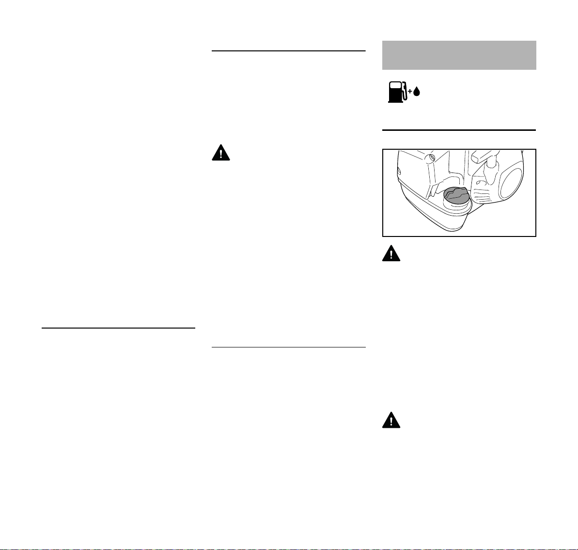
Fueling
Preparations
WARNING
When fueling on a slope, always position
the machine so that the fuel filler cap is
facing uphill.
N On level ground, position the
machine so that the fuel filler cap is
facing up.
N Before fueling, clean the fuel filler
cap and the area around it to ensure
that no dirt falls into the tank.
Always thoroughly shake the mixture in
the canister before fueling your
machine.
WARNING
In order to reduce the risk of fire and
personal injury from escaping gas vapor
and fumes, remove the fuel filler cap
carefully so as to allow any pressure
build-up in the tank to release slowly.
FS 360 C
29
Page 32

English
2709BA003 KN
2709BA004 KN
3
002BA411 KN
1
2
2
1
002BA631 KN
1
2
2
1
002BA632 KN
1
2
Opening the fuel filler cap
N Turn the fuel filler cap
counterclockwise until it can be
removed from the tank opening.
N Remove the fuel filler cap.
Refueling
Take care not to spill fuel while fueling
and do not overfill the tank.
Closing the fuel filler cap
Fitting the Full Harness
Fitting the full harness is described in
detail in the leaflet supplied with the
harness.
The type and style of the harness
depend on the market.
Fitting the Harness
Attaching Machine to Harness
N Attach the carabiner (1) to the
perforated rail (2) on the drive tube.
Disconnecting Machine from Harness
N Position fuel filler cap.
N Turn the fuel filler cap clockwise as
far as it will go and tighten it as
securely as possible by hand.
30
N Press down the bar on the
carabiner (1) and pull the perforated
rail (2) out of the carabiner.
N Put on the full harness (1).
N Adjust the length of the strap so that
the carabiner (2) is about a hand’s
width below your right hip.
N Attach the carabiner to the
machine's perforated rail (3) – see
“Attaching Machine to Harness”.
N Find the right attachment point for
the cutting attachment you are
using – see "Balancing the
Machine".
FS 360 C
Page 33

English
6BA009 KN
6BA010 KN
1
002BA484 KN
2
3
Balancing the Machine
The machine will balance differently
depending on the cutting attachment
mounted.
N Let the machine swing on the
harness until it stops moving –
change the connection point if
necessary
Hanging positions
Mowing heads, grass cutting blades and
brush knives should rest lightly on the
ground.
Putting down the machine in an
emergency
WARNING
As soon as it becomes apparent that a
dangerous situation is developing, the
machine must be put down quickly.
Practice setting down the machine
quickly. In order to avoid damage, when
practicing, do not throw the machine on
the ground.
Starting / Stopping the
Engine
Controls
1 Throttle trigger lockout
2 Throttle trigger
3 Stop switch with Run and Stop
positions. Depress the stop switch
(…) to switch off the ignition.
Circular saw blades should "hover"
approx. 8 in. (20 cm) above the ground.
FS 360 C
Function of stop switch and ignition
system
The stop switch is normally in the Run
position, i.e. when it is not depressed:
The ignition is switched on – the engine
is ready to start. Operate the stop switch
to switch off the ignition. The ignition is
switched on again automatically after
the engine stops.
31
Page 34

English
002BA489 KN
4
9926BA006 KN
5
1BA001 KN
5
6BA011 KN
6BA012 KN
Symbols on choke knob
Run position F – a hot engine is started
in this position or the engine runs in this
position.
Start position } – a cold engine is
started in this position.
Starting the Engine
N Press the manual fuel pump
bulb (4) at least five times – even if
the bulb is filled with fuel.
The choke knob is in the normal run
position F.
N If the engine is cold: Depress in the
outer edge (arrows) of the choke
knob (5) and then turn it to Start }.
Cranking
N Place the unit on the ground: It must
rest securely on the engine's guard
plate and the deflector. Check that
the cutting attachment is not
touching the ground or any other
obstacles.
N Make sure you have a firm footing,
either standing, stooping or
kneeling.
N Hold the unit firmly on the ground
with your left hand and press down
– do not touch the throttle trigger or
lockout lever.
N Hold the starter grip with your right
hand.
N Pull the starter grip steadily.
NOTICE
Do not pull out the starter rope all the
way – it might otherwise break.
N Do not let the starter grip snap back.
Guide it slowly back into the housing
so that the starter rope can rewind
properly.
N Continue cranking until the engine
runs.
N If the engine does not start: Turn the
choke knob to the start position }
and repeat starting procedure.
Using the machine
If you have started the machine for the
first time, refer to the notes on "Starting
for first time" in section "Other Hints on
Starting".
32
NOTICE
Do not stand or kneel on the drive tube.
FS 360 C
Page 35

English
6BA014 KN
002BA485 KN
6BA024 KN
N If the engine was started in the start
position }: Briefly press down the
trigger lockout and the pull the
throttle trigger at the same time –
the choke knob moves to the run
position (F) and the engine settles
down to idling speed.
Your machine is now ready for
operation.
WARNING
The cutting attachment must not rotate
in the Run F position with the engine at
idling speed.
If the cutting attachment rotates when
the engine is idling, refer to notes in
chapter on "Adjusting the Throttle
Cable" or have the machine serviced by
your dealer. STIHL recommends an
authorized STIHL servicing dealer.
N Attach the machine to the shoulder
strap.
N Machine is ready for use.
Stopping the Engine
N Depress the momentary contact
stop switch – the engine stops –
release the stop switch – it springs
back to the run position.
Other Hints on Starting
Starting for first time
N Depress the throttle trigger – do not
press down the throttle trigger
lockout.
If engine speed increases or the cutting
attachment rotates:
N Go to section "Stopping the
Engine".
N Go to "Adjusting the Throttle Cable".
If the engine speed does not increase,
your machine is ready for operation.
At very low outside temperatures
N Set the engine to winter operation if
necessary, see "Winter Operation".
N If the machine is very cold (frost on
machine), allow the engine to warm
up in the Start } position after
starting until normal operating
temperature is reached. Warning:
The cutting attachment runs.
If the engine does not start
N Check that all settings are correct.
N Check that there is fuel in the tank
and refuel if necessary.
N Check that the spark plug boot is
properly connected.
N Repeat the starting procedure.
Engine is flooded
N Move the choke lever to F and
continue cranking until the engine
runs.
Fuel tank run until completely dry
N After refueling, press the manual
fuel pump bulb at least five times –
even if the bulb is filled with fuel.
N Now start the engine.
FS 360 C
33
Page 36

English
9926BA061 KN
1
3
9926BA062 KN
2
Operating Instructions Air filter
During break-in period
A factory-new machine should not be
run at high revs (full throttle off load) for
the first three tank fillings. This avoids
unnecessary high loads during the
break-in period. As all moving parts
have to bed in during the break-in
period, the frictional resistances in the
engine are greater during this period.
The engine develops its maximum
power after about 5 to 15 tank fillings.
During Operation
After a long period of full throttle
operation, allow the engine to run for a
short while at idle speed so that engine
heat can be dissipated by the flow of
cooling air. This protects enginemounted components (ignition,
carburetor) from thermal overload.
After Finishing Work
Storing for a short period: Wait for the
engine to cool down. Empty the fuel tank
and keep the machine in a dry place,
well away from sources of ignition, until
you need it again. For longer out-ofservice periods – see "Storing the
Machine".
General Information
The filter has a very long service life.
Do not remove the filter cover or replace
the air filter as long as there is no
noticeable loss of power.
Dirty air filters reduce engine power,
increase fuel consumption and make
starting more difficult.
Replacing the Air Filter
Only if there is a noticeable loss of
engine power
N Set the choke knob to }.
N Loosen the screws (1).
N Remove the filter cover (2).
N Clean away loose dirt from around
the filter (3) and inside the filter
cover.
The air filter (3) is a pleated paper filter
element.
N Remove and check the filter
element (3) – replace if paper or
frame is dirty or damaged.
N Unpack the new filter.
NOTICE
Do not bend or twist the filter before
installation as it might otherwise be
damaged – do not use damaged filters.
N Fit the filter in the filter housing.
N Fit the filter cover.
Use only high quality air filters to ensure
the engine is protected from abrasive
dust.
STIHL recommends you use only
original STIHL air filters. The high quality
standard of these parts guarantees
trouble-free operation, a long engine life
and very long filter service lives.
34
FS 360 C
Page 37

English
Filter Element for Winter Operation
Maintenance and care of the special
filter element for winter operation are
described in the chapter on "Winter
Operation".
Engine Management M-Tronic
Exhaust emissions are controlled by the
design of the engine and components
(e.g. carburation, ignition, timing and
valve or port timing).
General Information
The M-Tronic controls fuel feed and
ignition timing electronically in all
operating conditions.
M-Tronic guarantees simple and fast
starts. The engine is started in the
Start } position irrespective of climatic
conditions or engine temperature. After
starting, the Start } position can be
maintained until the engine runs
smoothly.
M-Tronic ensures optimum engine
power at all times, very good
acceleration and automatic adjustment
to suit changing conditions.
For this reason there is no need to
change the carburetor setting – the
carburetor has no adjusting screws.
If the usual good running behavior and
engine power are not reached after an
extreme change in operating conditions,
contact your servicing dealer for
assistance.
STIHL recommends that you have
servicing and repair work carried out
exclusively by an authorized STIHL
servicing dealer.
FS 360 C
35
Page 38

English
2
1
9926BA016 KN
2
9926BA017 KN
3
2
9926BA018 KN
Winter Operation
At temperatures below +10°C (+50°F)
Preheating the carburetor
Repositioning the shutter allows heated
air to be drawn in from around the
cylinder and mixed with cold air – this
helps prevent carburetor icing.
An arrow (1) on the shroud indicates the
setting of the shutter (2) for summer or
winter operation. Meaning of symbols:
– "Sun" = summer operation
– "Snowflake" = winter operation
N Remove the screw (3) from the
shutter.
N Pull the shutter (2) out of the
shroud.
N Rotate the shutter (2) from the
summer position to the winter
position and refit it.
N Secure the shutter in position with
the screw (3).
At temperatures between
+10°C(+50°F) and +20°C(+70°F)
The machine can normally be operated
in this temperature range with the
shutter (2) in the summer position.
Change the position of the shutter if
necessary.
At temperatures above +20 °C (+70 °F)
N Always return the shutter (2) to the
summer position.
NOTICE
Do not operate the machine in the winter
position at temperatures above
+20 °C (+70 °F) because there is
otherwise a risk of engine running
problems and overheating.
At temperatures below -10°C (+14°F)
In extreme wintry conditions
– Temperatures below -10°C (+14°F)
– Powder or drifting snow
it is advisable to use the optional "cover
plate kit".
Two different cover plate kits are
available to suit the different tank caps.
36
FS 360 C
Page 39

English
4
5
9926BA063 KN
2
1
9926BA020 KN
The cover plate kits contain the following
parts for converting the power tool:
4 Cover plate partially blanks off the
slots in the starter housing
5 Synthetic fabric filter element for the
air filter
– Instruction sheet describing the
conversion.
For machines with tank cap with hinged
grip:
– O-ring for the tank filler cap
After installing the cover plate kit:
N Set the shutter (2) to the winter
position.
Cleaning the air filter
N Loosen filter cover mounting
screws.
N Remove the filter cover.
N Clean away loose dirt from around
the filter (5) and inside the filter
cover.
N Knock the filter (5) out on the palm
of your hand or blow it clear with
compressed air from the inside
outwards.
In case of stubborn dirt or sticky filter
fabric:
N Wash the filter in a clean, non-
flammable solution (e.g. warm
soapy water) and then dry.
Always replace a damaged filter.
Spark Plug
If there is a loss of engine power, the
machine is difficult to start or runs poorly
at idle, first check the spark plug.
Install a new spark plug after approx.
100 operating hours or earlier if the
electrodes are eroded/corroded.
The wrong fuel mix (too much engine oil
in the gasoline), a dirty air filter and
unfavorable running conditions (mostly
at part throttle etc.) affect the condition
of the spark plug. These factors cause
deposits to form on the insulator nose,
which may degrade performance.
Removing the Spark Plug
At temperatures above -10°C (+14°F)
N Remove the parts of the cover plate
kit and refit the standard parts for
summer operation.
Note for machines with tank cap with
hinged grip: The O-ring supplied with the
cover plate kit can be left on the
machine's tank cap.
Depending on the ambient temperature:
N Set the shutter (2) to the summer or
winter position.
FS 360 C
N Rotate the screw (1) in the cap (2)
until the screw head projects from it.
37
Page 40

English
3
9926BA021 KN
000BA039 KN
A
2
0000-GXX-1830-A0
3
1
4
3
2
9926BA022 KN
N Lift the front of the cap (2) and push
it to the rear to disengage.
N Leave the cap to one side.
N Pull off the spark plug boot (3).
N Unscrew the spark plug.
Wrong fuel mix (too much engine oil in
the gasoline), a dirty air filter and
unfavorable running conditions (mostly
at part throttle etc.) affect the condition
of the spark plug. These factors cause
deposits to form on the insulator nose
which may result in trouble in operation.
If engine is down on power, difficult to
start or runs poorly at idling speed, first
check the spark plug.
N Remove spark plug – see "Starting /
Stopping the Engine".
N Clean dirty spark plug.
38
N Check electrode gap (A) and
readjust if necessary – see
"Specifications".
N Use only resistor type spark plugs of
the approved range.
Rectify problems which have caused
fouling of spark plug:
N Too much oil in fuel mix.
N Dirty air filter.
N Unfavorable running conditions,
e.g. operating at part load.
Fit a new spark plug after approx. 100
operating hours or earlier if the
electrodes are badly eroded.
WARNING
To reduce the risk of fire and burn injury,
use only spark plugs authorized by
STIHL. Always press the spark plug
boot (1) snugly onto the spark plug
terminal (2).
Do not use a spark plug with a
detachable SAE adapter terminal (3).
Arcing may occur that could ignite
combustible fumes and cause a fire.
This can result in serious injuries or
damage to property.
N Only use resistor type spark plugs
with solid, non-threaded terminals
Installing the Spark Plug
N Screw the spark plug into the
cylinder.
N Press the spark plug boot firmly
onto the spark plug.
N Fit the cap (1) on the shroud from
the rear and push the lug (2) into the
opening (3) in the shroud at the
same time.
N Swing the cap forwards onto the
shroud, insert and tighten down the
screw (4) firmly.
FS 360 C
Page 41

English
2
2
1
2
1
1
002BA042 KN
Engine Running Behavior Storing the Machine Sharpening Metal Cutting
Blades
If engine running behavior is still
unsatisfactory after servicing the air filter
and adjusting the throttle cable, the
cause may be the muffler.
Have the muffler checked by a servicing
dealer for contamination
(carbonization).
STIHL recommends that you have
servicing and repair work carried out
exclusively by an authorized STIHL
servicing dealer.
If the machine is to remain out of use for
approx. 3 months or more
N Drain and clean the fuel tank in a
well ventilated place
N Dispose of fuel in accordance with
the regulations and having regard
for the environment
N Run the engine until the carburetor
is dry. This helps to prevent the
carburetor diaphragms sticking
together.
N Remove, clean and inspect the
cutting attachment. Treat metal
cutting attachments with protective
oil.
N Thoroughly clean the machine
N Store the machine in a dry and safe
place, out of the reach of children
and other unauthorized users
N Use a sharpening file (see "Special
Accessories") to sharpen dull
cutting attachments. In case of
more serious wear or nicks:
Resharpen with a grinder or have
the work done by a dealer – STIHL
recommends a STIHL servicing
dealer.
N Sharpen frequently, take away as
little metal as possible – two or three
strokes of the file are usually
enough.
FS 360 C
N Resharpen the teeth (1) uniformly –
do not alter the contour of the parent
blade (2) in any way.
See cutting attachment packaging for
additional sharpening instructions. Keep
the packaging for future reference.
39
Page 42

English
002BA406 KN
Balancing
N After resharpening about 5 times,
check the cutting attachment for
out-of-balance on a STIHL balancer
– see “Special Accessories” – or
have it checked by a dealer and rebalanced as necessary – STIHL
recommends a STIHL servicing
dealer.
Maintaining the Mowing
Head
Placing power tool on the ground
N Shut off the engine.
N Lay your power tool on its back so
that the cutting attachment
mounting face is pointing up.
Replacing Nylon Line
Always check the mowing head for signs
of wear before replacing the nylon line.
WARNING
If there are signs of serious wear,
replace the complete mowing head.
The nylon mowing line is referred to as
"nylon line" or "line" in the following.
The mowing head is supplied with
illustrated instructions for replacing the
nylon line. Keep the instructions for the
mowing head in a safe place.
N If necessary, remove the mowing
head.
Adjusting Nylon Line
STIHL AutoCut
N With the engine running, hold the
rotating mowing head above the
grass surface.
N Tap it on the ground once – fresh
line is advanced and the blade on
the deflector trims it to the right
length.
Fresh line is advanced every time the
mowing head is tapped on the ground.
For this reason observe the mowing
head's cutting performance during
operation. If the mowing head is tapped
on the ground too often, the line limiter
blade will unnecessarily cut off unused
lengths of nylon line.
Line feed operates only if both lines are
still at least 2.5 cm (1 in) long.
STIHL TrimCut
WARNING
To reduce the risk of injury, always shut
off the engine before adjusting the nylon
line by hand.
N Pull the spool up – rotate it about 1/6
turn counterclockwise until it
engages – and allow it to spring
back.
N Pull ends of the lines outward.
Repeat the above procedure as
necessary until both lines reach the
limiter blade on the deflector.
Rotating the spool from one stop to the
next advances about 4 cm (1 1/2 in) of
fresh line.
40
FS 360 C
Page 43

English
1
2
6BA021 KN
3
6BA022 KN
1
Replacing Nylon Line
STIHL PolyCut
Precut lengths of nylon line can be fitted
to the PolyCut in place of the cutting
blades.
STIHL DuroCut, STIHL PolyCut
WARNING
To reduce the risk of injury, always shut
off the engine before refilling the mowing
head.
N Fit nylon line in the mowing head as
described in the instructions
supplied.
Replacing Cutting Blades
STIHL PolyCut
Always check the mowing head for signs
of wear before installing new cutting
blades.
N Remove the mowing head.
N Replace blades as shown in the
illustrated instructions.
N Mount the mowing head on the
machine.
Inspection and Maintenance
by User
Clamped Area of Handlebar
N Check the freedom of movement of
the handlebar (1) in the clamp
moldings (2) at regular intervals.
Handlebar is difficult to move
WARNING
If there are signs of serious wear,
replace the complete mowing head.
The thermoplastic cutting blades are
referred to as "blades" in the following.
The mowing head is supplied with
illustrated instructions for replacing the
blades. Keep the instructions for the
mowing head in a safe place.
WARNING
To reduce the risk of injury, always shut
off the engine before installing the
blades.
FS 360 C
N Loosen the wing screw (3) just
enough for the handlebar to be
moved.
N Push the handlebar (1) sideways
out of the clamp.
N Soak a cloth in a clean, non-
flammable cleaning solution – do
not use a cleaning agent containing
oil or grease.
41
Page 44

English
2709BA022 KN
3BA035 KN
2
2709BA024 KN
2
N Thoroughly clean the clamp area of
the handlebar with the cloth and
cleaning solution.
N Line up the handlebar and secure it
in position with the wing screw.
Handlebar cannot be clamped firmly in
position
N Release handlebar in clamp as
described under "Handlebar is
difficult to move".
N Degrease clamp area on handlebar
and in clamp moldings.
N Line up the handlebar and secure it
in position with the wing screw.
Inspections and Maintenance
by Dealer
Maintenance Work
STIHL recommends that you have
servicing and repair work carried out
exclusively by an authorized STIHL
servicing dealer.
Fuel Pickup Body in Tank
N Check the pickup body in the fuel
tank every year and have it replaced
if necessary.
The pickup body should be positioned in
the area of the tank shown in the
illustration.
Spark arrestor in muffler and spacer
FS 460
FS 490
N If the engine is down on power,
have the spark arrestor in the
muffler checked.
N Check spacer (2) for damage.
N Have damaged spacer (2) replaced
immediately.
42
FS 360 C
Page 45

Antivibration elements
6BA015 KN
6BA026 KN
Four antivibration elements (arrows) are
installed between the powerhead and
the drive tube. Have the system checked
if there is a noticeable increase in
vibrations.
Both vibration gaps (arrows) are preset
to the same width at the factory. If the
size of the two vibration gaps varies
greatly and/or one of them closes up,
have your servicing dealer repair the
antivibration system.
Wear Guard on AV Housing
English
There is an easily replaced wear guard
on the side of the antivibration housing.
The guard may wear as a result of
rubbing against the side plate of the
harness durng operation and should be
replaced if necessary.
FS 360 C
43
Page 46

English
Maintenance and Care
The following intervals apply to normal operating conditions only. If your daily working time is longer or operating conditions are difficult (very dusty work area, etc.),
shorten the specified intervals accordingly.
before starting work
after finishing work or daily
after each refueling stop
weekly
monthly
every 12 months
if problem
if damaged
Visual inspection (condition, leaks) XX
Complete machine
Control handle Check operation XX
Air filter, paper filter
Air filter, synthetic fabric filter
Fuel tank Clean X
Manual fuel pump (if fitted)
Pickup body in fuel tank
Engine idle speed
Spark plug
Cooling inlets
Cylinder fins Clean
Clean X
Replace any damaged parts X
Visual inspection XX
1)
Replace
Visual inspection XX
Clean X
Replace XX
Check X
Have repaired by servicing dealer
2)
Check
2)
Replace
Check – the cutting attachment must not
turn
If the cutting attachment turns when the
engine is idling, have machine repaired
by servicing dealer
Readjust electrode gap X
Replace after every 100 operating hours
Visual inspection X
Clean X
2)
2)
2)
XXX
XX
X
X
X
X
as required
X
44
FS 360 C
Page 47

English
The following intervals apply to normal operating conditions only. If your daily working time is longer or operating conditions are difficult (very dusty work area, etc.),
shorten the specified intervals accordingly.
before starting work
after finishing work or daily
after each refueling stop
weekly
monthly
every 12 months
if problem
if damaged
as required
X
Spark arrestor in muffler
Spacer
Exhaust port
All accessible screws and nuts (not adjusting screws)
3)
Antivibration elements
2)
Check
Clean or replace
2)
Check X
2)
Replace
XX
Decoke after first 139 hours of operation, then every 150 hours of operation
Retighten X
4)
Check
Replace
2)
XX
X
X
X
Visual inspection XX
Cutting attachment
Replace X
Check tightness XX
Metal cutting attachment Sharpen XX
Safety labels Replace X
1)
Only if there is a noticeable loss of engine power
2)
STIHL recommends that this work be done by a STIHL servicing dealer
3)
Tighten down the muffler mounting screws firmly after first 10 to 20 hours of operation.
4)
see chapter "Inspections and Maintenance by Dealer", section "Antivibration Elements"
FS 360 C
45
Page 48

English
19
17
16
14
11
12
15
6
4
3
1
18
2
8
9
10
13
0000-GXX-1186-A0
#
7
5
Main Parts
1 Fuel Filler Cap
2 Starter Grip
3 Shutter
4 Spark Plug Boot
5 Muffler with Spark Arresting Screen
6 Spacer
7 Guard Plate
8 Throttle Trigger
9 Momentary Stop Switch
10 Throttle Trigger Lockout
11 Handlebar
12 Clamp Screw
13 Handle Support
14 Carrying Strip
15 Wear Guard
16 Choke Lever
17 Manual Fuel Pump
18 Filter Cover
19 Fuel Tank
# Serial Number
46
FS 360 C
Page 49

English
1
002BA412 KN
2
3
002BA417 KN
5
4
Definitions
1 Fuel Filler Cap
For closing the fuel tank.
2 Starter Grip
The grip of the pull starter, for
starting the engine.
3Shutter
With summer and winter positions.
Carburetor is heated in winter
position.
4 Spark Plug Boot
Connects the spark plug with the
ignition lead.
5 Muffler with Spark Arresting Screen
Muffler reduces exhaust noises and
diverts exhaust gases away from
operator.
Spark arresting screen is designed
to reduce the risk of fire.
6 Spacer
Designed to reduce the risk of burns
and fire.
7 Guard Plate
Protects the fuel tank.
8 Throttle Trigger
Controls the speed of the engine.
9 Momentary Stop Switch
Switches the engine's ignition off
and stops the engine.
10 Throttle Trigger Lockout
Must be depressed before the
throttle trigger can be activated.
11 Handlebar
For holding and controlling the unit
with the hand during operation.
12 Clamp Screw
Locks handlebar in selected
position.
13 Handle Support
Connects the shaft and bike handle.
14 Carrying Strip
The device to connect the clearing
saw to the harness.
15 Wear Guard
Protects the housing of the
antivibration-system from wear.
16 Choke Lever
Eases engine starting by enriching
mixture.
17 Manual Fuel Pump
Provides additional fuel feed for a
cold start.
18 Filter Cover
Encloses and protects the air filter.
19 Fuel Tank
For fuel and oil mixture.
1 Mowing Head
2 Deflector for Mowing Heads
3 Line Limiting Blade
4 Metal Mowing Tool
5 Deflector for Metal Mowing Tools
Definitions
1 Mowing Head
The cutting attachment, i. e.
mowing head, for different
purposes.
2 Deflector for Mowing Heads
Designed to reduce the risk of injury
from foreign objects flung
backwards toward the operator by
the cutting attachment and from
contact with the cutting attachment.
3 Line Limiting blade
Metal blade at the deflector in order
to keep the line of the mowing head
at the proper length.
4 Metal Mowing Tool
The cutting attachment, i. e. blade,
made from metal for different
purposes.
5 Deflector for Metal Mowing Tools
Designed to reduce the risk of injury
from foreign objects flung
backwards toward the operator by
the cutting attachment and from
contact with the cutting attachment.
FS 360 C
47
Page 50

English
7
002BA435 KN
6
6 Circular Saw Blade
7 Limit Stop for Circular Saw Blade
Definitions
6 Circular Saw Blade
Cutting attachment made of metal
for cutting wood.
7 Limit Stop for Circular Saw Blade
Designed to position the brushcutter
steady against the wood in order to
reduce the risk of injury from loss of
control from reactive forces such as
thrust out.
Specifications
EPA / CEPA
The Emission Compliance Period
referred to on the Emissions
Compliance Label indicates the number
of operating hours for which the engine
has been shown to meet Federal
emission requirements.
Category
A = 300 hours
B = 125 hours
C = 50 hours
Engine
Single cylinder two-stroke engine
Displacement: 37.7 cc
(2.30 cu.in)
Bore: 40 mm (1.57 in)
Stroke: 30 mm (1.18 in)
Engine power to
ISO 8893:
Idle speed: 2,800 rpm
Cut-off speed
(rated): 12,500 rpm
Max. output shaft
speed (cutting
attachment): 9,000 rpm
Ignition System
1.7 kW (2.3 bhp)
at 8,500 rpm
Spark plug (resistor
type): NGK CMR6H
Electrode gap: 0.5 mm (0.02 in)
This spark ignition system meets all
requirements of the Canadian
Interference-Causing Equipment
Standard CAN ICES-2/NMB-2.
Fuel System
All position diaphragm carburetor with
integral fuel pump
Fuel tank
capacity: 0.75 l (25.4 fl.oz)
Weight
Dry, without cutting attachment and
deflector
FS 360 C-EM LZ: 8.5 kg (18.7 lbs)
Overall length
without cutting attachment
FS 360 C-EM LZ: 1790 mm (70.47 in)
Features
C Convenience features
E Easy2Start
M M-Tronic
Z Spark arresting screen
Electronic magneto ignition
48
FS 360 C
Page 51

English
000BA073 KN
Maintenance and Repairs Disposal
Users of this unit should carry out only
the maintenance operations described
in this manual. STIHL recommends that
other repair work be performed only by
authorized STIHL servicing dealers
using genuine STIHL replacement parts.
Genuine STIHL parts can be identified
by the STIHL part number, the
{ logo and, in some cases, by
the STIHL parts symbol K. The
symbol may appear alone on small
parts.
For repairs of any component of this
unit’s air emissions control system,
please refer to the air emissions
systems warranty in this manual.
Observe all country-specific waste
disposal rules and regulations.
STIHL products must not be thrown in
the garbage can. Take the product,
accessories and packaging to an
approved disposal site for environmentfriendly recycling.
Contact your STIHL servicing dealer for
the latest information on waste disposal.
STIHL Limited Emission
Control Warranty Statement
This statement is given voluntarily,
based on the MOU (Memorandum of
Understanding) as agreed in April 1999
between Environmental Canada and
STIHL Limited
Your Warranty Rights and Obligations
STIHL Limited is pleased to explain the
Emission Control System Warranty on
your equipment type engine. In Canada
new 1999 and later model year small offroad equipment engines must be
designed, built and equipped, at the time
of sale, to meet the U.S. EPA
regulations for small non road engines.
The equipment engine must be free from
defects in materials and workmanship
which cause it to fail to conform with
U.S. EPA standards for the first two
years of engine use from the date of sale
to the ultimate purchaser.
STIHL Limited must warrant the
emission control system on your small
off-road engine for the period of time
listed below provided there has been no
abuse, neglect or improper maintenance
of your small off-road equipment engine.
Your emissions control system may
include parts such as the carburetor or
fuel-injection system, the ignition
system, and catalytic converter. Also
included may be hoses, belts,
connectors or other emission-related
assemblies.
Where a warrantable condition exists,
STIHL Limited will repair your small offroad equipment engine at no cost to you,
FS 360 C
49
Page 52

English
including diagnosis (if the diagnostic
work is performed at an authorized
dealer), parts, and labor.
Manufacturer's Warranty Coverage
In Canada 1999 and later model year
small off-road equipment engines are
warranted for two years. If any emissionrelated part on your engine is defective,
the part will be repaired or replaced by
STIHL Limited free of charge.
Owner's Warranty Responsibilities:
As the small off-road equipment engine
owner, you are responsible for the
performance of the required
maintenance listed in your instruction
manual. STIHL Limited recommends
that you retain all receipts covering
maintenance on your small off-road
equipment engine, but STIHL Limited
cannot deny warranty solely for the lack
of receipts or for your failure to ensure
the performance of all scheduled
maintenance.
Any replacement part or service that is
equivalent in performance and durability
may be used in non-warranty
maintenance or repairs, and shall not
reduce the warranty obligations of the
engine manufacturer.
As the small off-road equipment engine
owner, you should be aware, however,
that STIHL Limited may deny you
warranty coverage if your small off-road
equipment engine or a part has failed
due to abuse, neglect, improper
maintenance or unapproved
modifications.
You are responsible for presenting your
small off-road equipment engine to a
STIHL service center as soon as a
problem exists. The warranty repairs will
be completed in a reasonable amount of
time, not to exceed 30 days.
If you have any questions regarding your
warranty rights and responsibilities,
please contact a STIHL customer
service representative at www.stihl.ca
or you can write to:
STIHL Ltd.,
1515 Sise Road
Box 5666
CA-LONDON ONTARIO; N6A 4L6
Coverage by STIHL Limited
STIHL Limited warrants to the ultimate
purchaser and each subsequent
purchaser that your small off-road
equipment engine will be designed, built
and equipped, at the time of sale, to
meet all applicable regulations. STIHL
Limited also warrants to the initial
purchaser and each subsequent
purchaser that your engine is free from
defects in materials and workmanship
which cause the engine to fail to conform
with applicable regulations for a period
of two years.
Warranty Period
The warranty period will begin on the
date the utility equipment engine is
purchased by the initial purchaser and
you have signed and sent back the
warranty card to STIHL Ltd. If any
emission-related part on your engine is
defective, the part will be replaced by
STIHL Limited at no cost to the owner.
Any warranted part which is not
scheduled for replacement as required
maintenance, or which is scheduled only
for regular inspection to the effect of
"repair or replace as necessary" will be
warranted for the warranty period. Any
warranted part which is scheduled for
replacement as required maintenance
will be warranted for the period of time
up to the first scheduled replacement
point for that part.
Diagnosis
You, as the owner, shall not be charged
for diagnostic labor which leads to the
determination that a warranted part is
defective. However, if you claim
warranty for a component and the
machine is tested as non-defective,
STIHL Limited will charge you for the
cost of the emission test. Mechanical
diagnostic work will be performed at an
authorized STIHL servicing dealer.
Emission test may be performed either
at
STIHL Incorporated,
536 Viking Drive, P.O. Box 2015,
Virginia Beach, VA 23452
or at any independent test laboratory.
Warranty Work
STIHL Limited shall remedy warranty
defects at any authorized STIHL
servicing dealer or warranty station. Any
such work shall be free of charge to the
owner if it is determined that a warranted
part is defective. Any manufacturerapproved or equivalent replacement
part may be used for any warranty
maintenance or repairs on emissionrelated parts and must be provided
without charge to the owner. STIHL
Limited is liable for damages to other
engine components caused by the
failure of a warranted part still under
warranty.
50
FS 360 C
Page 53

English
The following list specifically defines the
emission-related warranted parts:
– Air Filter
– Carburetor (if applicable)
– Fuel Pump
– Choke (Cold Start Enrichment
System) (if applicable)
– Control Linkages
– Intake Manifold
– Magneto or Electronic Ignition
System (Ignition Module or
Electronic Control Unit)
– Fly Wheel
– Spark Plug
– Injection Valve (if applicable)
– Injection Pump (if applicable)
– Throttle Housing (if applicable)
– Cylinder
– Muffler
– Catalytic Converter (if applicable)
– Fuel Tank
– Fuel Cap
– Fuel Line
– Fuel Line Fittings
– Clamps
– Fasteners
Where to make a Claim for Warranty
Service
Bring the product to any authorized
STIHL servicing dealer and present the
signed warranty card.
Maintenance Requirements
The maintenance instructions in this
manual are based on the application of
the recommended 2-stroke fuel-oil
mixture (see also instruction "Fuel").
Deviations from this recommendation
regarding quality and mixing ratio of fuel
and oil may require shorter maintenance
intervals.
Limitations
This Emission Control Systems
Warranty shall not cover any of the
following:
1. repair or replacement required
because of misuse, neglect or lack
of required maintenance
2. repairs improperly performed or
replacements not conforming to
STIHL Limited specifications that
adversely affect performance
and/or durability, and alterations or
modifications not recommended or
approved in writing by STIHL
Limited
3. replacement of parts and other
services and adjustments
necessary for required maintenance
at and after the first scheduled
replacement point
FS 360 C
51
Page 54

Table des matières
français
Indications concernant la présente
Notice d'emploi 53
Prescriptions de sécurité et
techniques de travail 54
Combinaisons autorisées d'outil de
coupe, de capot protecteur, de
butée et de harnais 73
Montage du guidon 75
Réglage du câble de commande
des gaz 78
Montage des dispositifs de sécurité 79
Montage de l'outil de coupe 80
Carburant 84
Ravitaillement en carburant 85
Utilisation du harnais double 86
Équilibrage 87
Mise en route / arrêt du moteur 88
Instructions de service 90
Filtre à air 91
Gestion moteur 92
M-Tronic 92
Utilisation en hiver 93
Bougie 94
Fonctionnement du moteur 96
Rangement 96
Affûtage des outils de coupe
métalliques 97
Entretien de la tête faucheuse 97
Contrôle et maintenance par
l'utilisateur 99
Contrôle et maintenance par le
revendeur spécialisé 99
Instructions pour la maintenance et
l'entretien 101
Principales pièces 103
Caractéristiques techniques 105
Instructions pour les réparations 106
Mise au rebut 106
Garantie de la Société STIHL
Limited relative au système
antipollution 107
Ne confiez votre débroussailleuse qu'à
des personnes qui ont lu et parfaitement
compris la présente Notice d'emploi.
Pour obtenir les meilleures
performances et être satisfait de votre
débroussailleuse STIHL, il est important
de lire et de bien comprendre les
prescriptions de sécurité et les
instructions à suivre pour l'utilisation et
la maintenance, indiquées dans le
chapitre « Prescriptions de sécurité et
techniques de travail », avant d'utiliser
votre débroussailleuse. Pour de plus
amples informations, vous pouvez
consulter le site www.stihlusa.com.
Si vous ne comprenez pas parfaitement
certaines instructions de cette Notice
d'emploi, veuillez consulter votre
revendeur ou distributeur STIHL.
AVERTISSEMENT
Une débroussailleuse étant un outil de
coupe tournant à haute vitesse, il faut
respecter des prescriptions de sécurité
particulières afin de réduire le risque de
blessure. Une utilisation imprudente ou
inadéquate risque de causer des
blessures graves, voire mortelles.
Assurez-vous que votre machine est
munie du capot protecteur, de la
poignée et du harnais qui conviennent
pour le type d'outil de coupe employé.
Toujours porter un équipement
approprié pour se protéger les yeux.
Notice d'emploi d'origine Imprimé sur papier blanchi sans chlore
L'encre d'imprimerie contient des huiles végétales, le papier
est recyclable.
© ANDREAS STIHL AG & Co. KG, 2018
0458-746-8221-D. VA4.L18.
0000007311_006_F
52
La présente Notice d'emploi est protégée par des droits d'auteur. Tous droits réservés, en particulier tout droit de copie, de traduction et de traitement avec des systèmes électroniques quelconques.
FS 360 C
Page 55

français
Indications concernant la
présente Notice d'emploi
Pictogrammes
Tous les pictogrammes appliqués ou
estampés sur la machine sont expliqués
dans la présente Notice d'emploi.
Selon le modèle, la machine peut porter
les pictogrammes suivants :
Réservoir pour le
mélange d'essence et
d'huile
Appuyer pour actionner
la soupape de
décompression
Pompe d'amorçage
manuelle
Appuyer pour actionner
la pompe d'amorçage
manuelle
Orifice de remplissage
pour graisse à réducteur
Mode d'admission d'air
«été»
Mode d'admission d'air
«hiver»
Chauffage de poignées
Symboles employés dans le texte
De nombreuses prescriptions de
sécurité et instructions à suivre à
l'utilisation de la machine sont illustrées.
Les opérations ou procédures décrites
dans la présente Notice d'emploi
peuvent être mises en évidence de
différentes manières :
N Un point repère une opération ou
une procédure.
La description d'une opération ou d'une
procédure qui se réfère directement à
une illustration reprend les numéros des
pièces qui figurent sur l'illustration. Par
exemple :
N Enlever la vis (1).
N Enlever la grille pare-étincelles (2)
du silencieux en la tirant vers le
haut.
En plus des instructions à suivre à
l'utilisation, la présente Notice d'emploi
peut renfermer des paragraphes dont il
faut tout particulièrement tenir compte.
De tels paragraphes sont repérés par
les symboles et les termes
d'avertissement décrits ci-après :
DANGER
Signale une situation dangereuse à
éviter car elle causerait un risque de
blessure grave, voire mortelle.
AVERTISSEMENT
Signale une situation dangereuse à
éviter car elle pourrait causer un risque
de blessure grave, voire mortelle.
AVIS
Signale un risque d'endommagement de
biens matériels, y compris le risque
d'endommagement de la machine ou de
ses composants.
Développement technique
La philosophie de STIHL consiste à
poursuivre le développement continu de
tous ses produits. C'est pourquoi les
différents produits font de temps en
temps l'objet de modifications et de
perfectionnements techniques. Il est
donc possible que des modifications et
des perfectionnements techniques
réalisés entre-temps ne figurent pas
encore dans la présente Notice
d'emploi. Si par conséquent les
caractéristiques de fonctionnement ou
la configuration de votre machine
diffèrent des descriptions de la présente
Notice d'emploi, veuillez consulter votre
revendeur spécialisé STIHL ou le
distributeur STIHL de votre région qui
pourra vous donner des informations
complémentaires et vous conseiller.
FS 360 C
53
Page 56

français
Prescriptions de sécurité et
techniques de travail
Une débroussailleuse
étant un dispositif à
moteur à haut régime et à
grande vitesse de coupe,
parfois muni de couteaux
acérés, il faut respecter
des prescriptions de
sécurité particulières afin
de réduire le risque de
blessure.
Il est important de lire, de
comprendre parfaitement et d'observer les
prescriptions de sécurité
et les avertissements ciaprès. Il convient de relire
périodiquement la Notice
d'emploi et les prescriptions de sécurité. Une
utilisation imprudente ou
inadéquate peut entraîner des lésions graves,
voire mortelles.
La terminologie utilisée dans cette
Notice d'emploi pour la dénomination de
la machine dépend des différents outils
de coupe qu'il est permis de monter sur
la machine considérée. Le terme
« coupe-herbe » est employé pour
désigner un modèle de la gamme de
machines FS (débroussailleuses)
équipé d'une tête faucheuse munie d'un
fil de coupe en matière synthétique
(nylon) ou d'une tête faucheuse munie
de couteaux en matière synthétique
souple (comme par ex. de la tête
faucheuse PolyCut). Le terme
« débroussailleuse » désigne une
machine équipée d'un couteau
métallique rigide. De nombreux modèles
FS peuvent être utilisés soit comme
coupe-herbe, soit comme
débroussailleuse – c'est pourquoi dans
la présente Notice la machine est
appelée « coupe-herbe /
débroussailleuse ». Certains modèles
FS légers et / ou de petite taille peuvent
être utilisés uniquement comme coupeherbe et dans ce cas il n'est pas permis
de les utiliser avec des couteaux
métalliques.
Le terme « débroussailleuse forestière »
désigne une débroussailleuse de haute
puissance spécialement conçue pour
être utilisée avec une scie circulaire pour
couper des rejets ou de petits arbres.
AVERTISSEMENT
Comme le précisent les indications
données sur les pages suivantes des
présentes prescriptions de sécurité,
pour réduire le risque de blessure, il faut
s'assurer que la machine est bien
équipée du capot protecteur, de la butée
et du harnais qui conviennent pour le
type d'outil de coupe employé. Monter
exclusivement des outils de coupe
expressément autorisés par STIHL pour
être utilisés sur ce modèle FS.
Demandez à votre revendeur STIHL de
vous montrer comment utiliser votre
machine. Respectez toutes les règles de
sécurité, normes et prescriptions locales
applicables.
AVERTISSEMENT
Ne pas prêter ou louer la machine sans
y joindre la Notice d'emploi. S'assurer
que toute personne utilisant cette
machine comprend parfaitement les
instructions de cette Notice d'emploi.
AVERTISSEMENT
L'utilisation de cette machine peut être
dangereuse. Si le fil de coupe ou les
couteaux en rotation entrent en contact
avec une partie du corps de l'utilisateur,
ils risquent de causer des coupures.
Lorsque l'outil de coupe touche des
objets solides tels que des pierres ou
des morceaux de métal, il peut les
projeter au loin ; l'utilisateur ou des
personnes qui pourraient se trouver à
proximité risquent d'être touchés, soit
directement, soit par ricochet. Le fait de
heurter de tels objets peut endommager
l'outil de coupe et les couteaux peuvent
se fissurer, s'ébrécher ou se casser. Les
objets projetés y compris les éclats des
têtes faucheuses ou des couteaux
endommagés peuvent causer des
blessures graves, voire mortelles, tant à
l'utilisateur qu'à d'autres personnes qui
pourraient se trouver à proximité. STIHL
recommande de ne pas utiliser des
couteaux rigides pour couper sur des
surfaces couvertes de pierres.
Utiliser la débroussailleuse avec l'outil
de coupe qui convient pour couper de
l'herbe, des broussailles, du bois ou
d'autres matières similaires.
54
FS 360 C
Page 57

français
AVERTISSEMENT
Ne pas l'utiliser pour d'autres travaux,
car un tel usage non autorisé pourrait
causer des blessures ou des dégâts
matériels et aussi endommager la
machine.
AVERTISSEMENT
Les jeunes encore mineurs ne sont pas
autorisés à manier cette machine.
Veillez à ce que des personnes, en
particulier des enfants, ou des animaux
ne se trouvent pas sur l'aire d'utilisation
de la machine.
AVERTISSEMENT
Afin de réduire le risque de blessure de
personnes qui pourraient se trouver à
proximité, et d'endommagement de leur
propriété, ne jamais laisser la machine
en marche sans surveillance.
Lorsqu'elle n'est pas employée (par ex.
au cours d'une pause), il faut arrêter le
moteur et prendre les précautions
nécessaires pour que la machine ne
puisse pas être utilisée par des
personnes non autorisées.
La plupart de ces prescriptions de
sécurité et avertissements sont valables
pour toutes les débroussailleuses
STIHL. Divers modèles peuvent
toutefois avoir des composants ou des
commandes différents. Pour la
description des commandes et du
fonctionnement des composants du
modèle considéré, consulter le chapitre
correspondant de la Notice d'emploi.
Les prescriptions à suivre pour utiliser
une débroussailleuse en toute sécurité
s'appliquent :
1. à l'utilisateur ;
2. à la machine ;
3. à l'utilisation de la machine.
L'UTILISATEUR
Condition physique
L'utilisateur doit être en bonne condition
physique et mentale, et il ne doit pas
être sous l'influence de substances
quelconques (drogues, alcool, etc.)
risquant d'entraver sa vue, sa dextérité
ou sa capacité de jugement. Ne jamais
travailler avec cette machine en étant
fatigué.
AVERTISSEMENT
Il faut toujours rester vigilant – si l'on se
sent fatigué, faire une pause. La fatigue
peut entraîner une perte de contrôle. Le
travail avec une machine peut être
fatigant. Si son état de santé risque
d'être aggravé par un travail fatigant,
l'utilisateur devrait consulter un médecin
avant d'entreprendre des travaux avec
cette machine.
AVERTISSEMENT
L'utilisation prolongée d'une telle
machine (ou de tout autre dispositif à
moteur) exposant l'utilisateur aux
vibrations peut provoquer la maladie des
« doigts blancs » (phénomène de
Raynaud) ou le syndrome du tunnel
carpien.
Ces phénomènes réduisent l'aptitude
des mains à percevoir et à régler la
température, entraînant une insensibilité
des doigts et une sensation brûlante.
Cela peut causer des troubles nerveux
et circulatoires ainsi qu'une nécrose.
Tous les facteurs qui contribuent à la
maladie des doigts blancs ne sont pas
connus, mais on sait que le temps froid,
le fait de fumer et des maladies ou des
conditions physiques affectant les
artères et la circulation sanguine, ainsi
qu'un niveau de vibrations élevé et de
longues périodes d'exposition aux
vibrations, comptent parmi les facteurs
qui favorisent le développement de la
maladie des doigts blancs. Afin de
réduire le risque de la maladie des
doigts blancs et du syndrome du tunnel
carpien, veuillez tenir compte des
indications suivantes :
– La plupart des machines STIHL
sont livrables avec un système
antivibratoire (« AV ») conçu pour
réduire la transmission, aux mains
de l'utilisateur, des vibrations
engendrées par la machine. Un
système AV est recommandé pour
les personnes qui utilisent des
machines régulièrement ou pendant
d'assez longues périodes.
– Porter des gants et prendre soin
d'avoir toujours les mains au chaud.
FS 360 C
55
Page 58

français
– Veiller à ce que le système AV soit
bien entretenu. Sur une machine
avec des composants desserrés ou
avec des éléments AV
endommagés ou usés, le taux de
vibrations est plus élevé.
– Toujours saisir fermement les
poignées, mais ne pas les serrer
constamment avec une pression
excessive. Faire des pauses
fréquentes.
Toutes les précautions énoncées ciavant ne peuvent pas exclure le risque
de la maladie des doigts blancs ou d'un
syndrome du tunnel carpien. C'est
pourquoi les personnes qui utilisent
continuellement ou régulièrement une
telle machine doivent attentivement
surveiller l'état de leurs mains et de leurs
doigts. Si l'un des symptômes ci-dessus
se manifeste, consulter immédiatement
un médecin.
AVERTISSEMENT
Le système d'allumage de la machine
STIHL génère un champ
électromagnétique de très faible
intensité. Ce champ peut produire des
interférences avec certains stimulateurs
cardiaques. Afin de réduire le risque de
conséquences graves, voire mortelles,
les personnes portant un stimulateur
cardiaque devraient consulter leur
médecin et le fabricant de leur
stimulateur cardiaque avant de travailler
avec cette machine.
Vêtements appropriés
Pour réduire le risque de blessure,
l'utilisateur devrait porter un équipement
de protection approprié.
AVERTISSEMENT
Le capot protecteur de la machine ne
peut pas protéger l'utilisateur contre
tous les objets (pierres, morceaux de
verre, fils de fer etc.) projetés par l'outil
de coupe en rotation. Les objets projetés
peuvent aussi ricocher et toucher
l'utilisateur.
AVERTISSEMENT
Pour réduire le risque de
blessure aux yeux, ne
jamais travailler avec la
machine sans lunettes de
protection ou lunettes
bien ajustées à verres de
sécurité, avec éléments
de protection supérieurs
et latéraux adéquats,
conformément à la norme
ANSI Z 87 « + » (ou à la
norme nationale applicable). Afin de réduire le
risque de blessure au
visage, STIHL recommande de porter, en plus
des lunettes de protection ou de sécurité – une
visière protégeant le
visage.
Pour réduire les risques
de blessure à la tête, si
de tels risques se présentent, porter un casque
de protection homologué.
Le bruit de la machine
peut causer des lésions
de l'ouïe. Porter des protège-oreilles (tampons ou
capsules insonorisantes)
pour se protéger l'ouïe.
Les personnes qui travaillent régulièrement et
longuement avec cette
machine devraient faire
vérifier leur ouïe
périodiquement.
56
FS 360 C
Page 59

français
002BA479 KN
En travaillant avec des protège-oreilles,
il faut faire tout particulièrement
attention, parce que des bruits signalant
un danger (cris, signaux sonores etc.)
sont moins bien perceptibles.
En travaillant avec la
machine et pour manipuler les couteaux ou lames
métalliques, toujours porter des gants de travail
robustes (par ex. en cuir
ou en autre matière résistante). Des gants
robustes et antidérapants assurent une
bonne prise et protègent
les mains.
Les vêtements doivent
être résistants et bien
ajustés, tout en laissant
une liberté de mouvement totale. Porter un
pantalon long en tissu
robuste, pour se protéger les jambes. Ne pas
travailler en short, en
sandales ou pieds nus.
Éviter de porter une veste ample, une
écharpe, une cravate, des bijoux, un
pantalon large ou à revers, de longs
cheveux flottants et tout ce qui risquerait
de se prendre dans les branches, les
buissons ou les pièces en mouvement
de la machine. Les personnes aux
cheveux longs doivent les nouer ou les
assurer au-dessus des épaules.
Une bonne prise au sol
est très importante. Porter des chaussures
robustes à semelle antidérapante. Il est
recommandé de porter
des chaussures de sécurité avec coquille en
acier.
LA MACHINE
Pour les illustrations et les définitions
des composants de la machine, voir le
chapitre « Principales pièces ».
AVERTISSEMENT
Ne jamais apporter une modification
quelconque sur la machine. Utiliser
exclusivement les équipements livrés
par STIHL et expressément autorisés
par STIHL pour ce modèle STIHL bien
déterminé. Même si certains
équipements non autorisés pouvaient
être rapportés sur la machine STIHL,
leur usage serait extrêmement
dangereux. En ce qui concerne les outils
de coupe autorisés par STIHL pour cette
machine, voir le chapitre
« Combinaisons autorisées d'outil de
coupe, de capot protecteur, de butée et
de harnais » dans la Notice d'emploi ou
dans le catalogue STIHL « Outils de
coupe, pièces et accessoires ».
Si la machine a été soumise à des
sollicitations sortant du cadre de
l'utilisation normale (par ex. si elle a été
soumise à des efforts violents, en cas de
choc ou de chute), avant de poursuivre
le travail, il faut impérativement
s'assurer qu'elle se trouve en parfait état
de fonctionnement. Contrôler tout
particulièrement l'étanchéité du système
de carburant (absence de fuites) et la
fiabilité des commandes et des
dispositifs de sécurité. Il ne faut en
aucun cas continuer d'utiliser cette
machine si elle est endommagée. En
cas de doute, la faire contrôler par le
revendeur spécialisé STIHL.
L'UTILISATION DE LA MACHINE
Transport de la machine
AVERTISSEMENT
Afin de réduire le risque de blessure par
suite d'une perte de contrôle et d'un
contact avec le couteau ou le fil de
coupe, ne jamais porter ou transporter le
dispositif à moteur avec l'outil de coupe
en mouvement.
Toujours porter la machine à
l'horizontale. Saisir le tube de telle sorte
que la machine soit bien équilibrée, à
l'horizontale. Le porter avec le silencieux
chaud placé du côté opposé au corps.
FS 360 C
57
Page 60

français
AVERTISSEMENT
Afin de réduire le risque
de brûlure, ne pas
toucher aux pièces de la
machine ou au carter du
réducteur qui deviennent
très chauds au cours de l'utilisation.
AVERTISSEMENT
Toujours arrêter le moteur, et s'assurer
que l'outil de coupe est arrêté, avant de
poser la débroussailleuse sur le sol.
Pour le transport dans un véhicule,
assurer la machine afin qu'elle ne risque
pas de se renverser, ce qui pourrait
l'endommager et entraîner une fuite de
carburant. STIHL recommande de
recouvrir les couteaux ou lames
métalliques avec le protecteur de
transport (accessoire optionnel).
Carburant
La machine STIHL fonctionne avec un
mélange d'essence et d'huile (voir
chapitre « Carburant » de la Notice
d'emploi).
AVERTISSEMENT
L'essence est un carburant extrêmement
inflammable. Le carburant renversé et
enflammé par une étincelle ou par toute autre
source d'allumage peut
entraîner un incendie,
ainsi que de graves brûlures et des dégâts
matériels importants. Il
faut donc être très prudent lors de la
manipulation de
l'essence ou du mélange.
Ne pas fumer et ne pas
s'approcher du carburant
ou de la machine avec
une flamme ou un feu
quelconque. À noter que
des vapeurs de carburant
peuvent s'échapper du
système d'alimentation
en carburant.
Instructions pour faire le plein
AVERTISSEMENT
Afin de réduire le risque de brûlures
graves, ne jamais essayer de refaire le
plein tant que la machine n'est pas
totalement séparée de l'utilisateur.
AVERTISSEMENT
Faire le plein de la machine à un endroit
bien aéré, seulement en plein air.
Toujours arrêter le moteur et attendre
qu'il soit refroidi avant de refaire le plein.
Suivant le carburant utilisé, les
conditions climatiques et le système
d'aération du réservoir à carburant, les
vapeurs d'essence emprisonnées dans
le réservoir à carburant peuvent se
trouver sous pression.
Afin de réduire le risque de brûlures ou
d'autres blessures, à l'échappement de
vapeurs et de gaz d'essence, enlever
prudemment le bouchon du réservoir à
carburant de la machine, de telle sorte
qu'une surpression interne puisse
s'échapper lentement. Ne jamais
enlever le bouchon du réservoir à
carburant lorsque le moteur est en
marche.
Pour faire le plein, choisir un endroit bien
dégagé et, avant de lancer le moteur,
aller au moins à 10 pieds (3 m) du lieu
où l'on a fait le plein. Avant de lancer le
moteur, essuyer le carburant qui aurait
pu déborder.
AVERTISSEMENT
En refaisant le plein et au
cours de l'utilisation, toujours vérifier s'il n'y a pas
de fuite. Si l'on constate
une fuite de carburant, ne
pas laisser le moteur en
marche ou le redémarrer
avant d'avoir éliminé la
fuite et essuyé le carburant qui s'est échappé.
Ne pas se renverser de
l'essence sur les vêtements. Le cas échéant,
se changer
immédiatement.
58
FS 360 C
Page 61

français
001BA220 KN
001BA227 KN
001BA226 KN
AVERTISSEMENT
Afin de réduire le risque de fuite de
carburant et d'incendie par suite du
desserrage du bouchon du réservoir à
carburant, il faut que le bouchon du
réservoir soit correctement positionné et
fermement serré dans le goulot de
remplissage du réservoir à carburant.
Divers modèles peuvent être munis de
différents bouchons de réservoir à
carburant.
Bouchon à ailette rabattable, à
ouverture/fermeture sans aucun
outillage
À cet effet, sur ce bouchon de réservoir
STIHL, relever l'ailette rabattable située
au-dessus du bouchon de telle sorte
qu'elle se trouve à angle droit par
rapport au bouchon. Présenter le
bouchon de telle sorte que les repères
de positionnement en relief sur l'ailette
rabattable et sur l'orifice du réservoir à
carburant coïncident. En agissant sur
l'ailette, presser fermement le bouchon
vers le bas en le faisant tourner le plus
loin possible (env. 1/4 de tour) dans le
sens des aiguilles d'une montre.
Rabattre l'ailette de telle
sorte qu'elle affleure avec
le dessus du bouchon.
Saisir le bouchon et
s'assurer qu'il est bien
serré. Si l'ailette rabattable n'affleure pas avec
le bouchon du réservoir
et que le talon de l'ailette
rabattable ne se prend
pas dans le logement
prévu dans le goulot de
remplissage du réservoir, ou si le bouchon
peut bouger dans le goulot de remplissage, cela
signale que le bouchon
n'est pas correctement
positionné et serré. Il faut
alors recommencer toute
la procédure décrite ciavant.
Décalage entre les parties supérieure et
inférieure du bouchon, ou bouchon
endommagé ou cassé
N Si le bouchon ne s'enfonce pas
complètement dans l'orifice lorsque
les repères de positionnement sont
alignés et/ou si le bouchon n'est pas
correctement serré lorsqu'on le fait
tourner, cela provient probablement
du fait que la partie inférieure du
bouchon a été prématurément
tournée dans la position de
fermeture (et est décalée par
rapport à la partie supérieure). Un
tel décalage peut s'être produit au
cours de la manipulation, du
nettoyage ou d'une tentative de
serrage incorrecte.
À
gauche :
Partie inférieure du bouchon
en position de fermeture
(avec un interstice visible)
À droite : Partie inférieure du bouchon
dans la position correcte
pour le montage
N Pour ramener le bouchon dans la
position ouverte nécessaire pour le
montage, faire tourner le bouchon
(avec l'ailette relevée) jusqu'à ce
qu'il s'enfonce complètement dans
le goulot de remplissage. Ensuite,
tourner le bouchon dans le sens
inverse des aiguilles d'une montre,
le plus loin possible
(env. 1/4 de tour) – la partie
inférieure du bouchon est ainsi
tournée dans la position correcte.
Après cela, tourner le bouchon dans
le sens des aiguilles d'une montre et
le fermer normalement.
N S'il n'est toujours pas possible de
serrer correctement le bouchon,
c'est que ce dernier est
FS 360 C
59
Page 62

français
endommagé ou cassé ; il faut alors
immédiatement arrêter l'utilisation
de la machine et la faire réparer par
le revendeur spécialisé STIHL.
Bouchon à visser
AVERTISSEMENT
S'il n'est pas fermement
serré, le bouchon du
réservoir peut se desserrer sous l'effet des
vibrations. Une grande
quantité de carburant
peut alors s'échapper.
Pour écarter le risque de
perte de carburant et
d'incendie, serrer le bouchon le plus fermement
possible, à la main.
Pour de plus amples informations à ce
sujet, consulter également le chapitre
« Faire le plein de carburant » de la
Notice d'emploi.
Avant la mise en route
AVERTISSEMENT
Avant la mise en route, toujours
s'assurer que la machine se trouve en
bon état de fonctionnement, en
particulier la gâchette d'accélérateur, le
blocage de gâchette d'accélérateur, le
commutateur d'arrêt temporaire, l'outil
de coupe, le capot protecteur et le
harnais. La gâchette d'accélérateur doit
pouvoir être actionnée facilement et elle
doit toujours revenir d'elle-même en
position de ralenti. Ne jamais essayer de
modifier les éléments de commande ou
les équipements de sécurité.
AVERTISSEMENT
Contrôler si le système de carburant ne
présente pas de fuites et en particulier si
les pièces visibles, par ex. le bouchon
de remplissage du réservoir, les
raccords des tuyaux flexibles, la pompe
d'amorçage manuelle (seulement sur
les machines équipées d'une pompe
d'amorçage manuelle), ne sont pas
endommagées. Ne pas mettre le moteur
en marche en cas de fuites ou
d'endommagements – risque
d'incendie ! Le cas échéant, avant de
réutiliser la machine, la faire réparer par
le revendeur spécialisé.
AVERTISSEMENT
Ne jamais travailler avec cette machine
s'il est endommagé, pas correctement
ajusté ou entretenu, pas complètement
assemblé ou bien pas assemblé de
façon fiable.
AVERTISSEMENT
Ne pas fixer un outil de coupe sur une
machine sans monter correctement
toutes les pièces requises. Si l'on
n'utilise pas les pièces qui conviennent,
le couteau ou la tête faucheuse risque
d'être projeté au loin et de blesser
grièvement l'utilisateur ou des
personnes qui pourraient se trouver à
proximité.
AVERTISSEMENT
L'outil de coupe doit être correctement
serré et dans un état garantissant un
fonctionnement en toute sécurité.
Vérifier si des pièces ne sont pas
desserrées (écrous, vis etc.) et si les
têtes faucheuses ne sont pas
endommagées, ou si les couteaux ne
sont pas fissurés, gauchis, déformés ou
endommagés. Remplacer les têtes
faucheuses ou les couteaux
endommagés, avant de continuer
d'utiliser la machine. Veiller à ce que les
couteaux soient toujours bien affûtés.
Les poignées doivent être toujours
propres et sèches : veiller tout
particulièrement à ce qu'elles ne soient
pas mouillées ou poisseuses, enduites
d'huile, de carburant, de graisse ou de
résine – pour que l'on puisse
parfaitement les tenir et contrôler la
machine.
AVERTISSEMENT
S'assurer que le contact de câble
d'allumage est bien serré sur la bougie –
un contact desserré peut produire un arc
électrique qui risque d'enflammer les
vapeurs de carburant et de causer un
incendie.
60
FS 360 C
Page 63

français
A
000BA006 KN
B
000BA007 KN
AVERTISSEMENT
Afin de réduire les
risques de blessure de l'utilisateur
par suite d'un
contact avec les
couteaux ou avec
le fil de coupe, et
par des objets projetés, s'assurer
que la machine est
bien équipée du
capot protecteur,
de la butée et du
harnais qui
conviennent pour
le type d'outil de
coupe utilisé (voir
le tableau du chapitre
« Combinaisons
autorisées d'outil
de coupe, de
capot protecteur,
de butée et de
harnais »).
Comme on peut le voir sur ce tableau,
pour l'utilisation de certains outils de
coupe, il peut être indispensable de
changer de capot protecteur, de butée
et / ou de harnais.
Le capot protecteur et le tablier (dans le
cas où ce dernier est nécessaire)
doivent toujours être correctement
ajustés (voir chapitres « Montage du
capot protecteur » et « Montage de
l'outil de coupe » dans la présente
Notice d'emploi).
Les flèches appliquées sur le capot
protecteur (A) et sur la butée (B) (vus
par le bas) indiquent le sens de rotation
correct de l'outil de coupe. Vu par le
haut, l'outil de coupe tourne dans le sens
inverse des aiguilles d'une montre.
Certains des symboles suivants peuvent
être estampés sur la face extérieure du
capot protecteur pour indiquer la
combinaison d'outil de coupe et de
capot protecteur autorisée.
Ce capot protecteur peut
être utilisé en combinaison avec des têtes
faucheuses.
Ce capot protecteur peut
être utilisé en combinaison avec des couteaux à
herbe.
Ce capot protecteur peut
être utilisé en combinaison avec des couteaux à
taillis.
Ce capot protecteur ne
doit pas être utilisé en
combinaison avec des
têtes faucheuses.
Ce capot protecteur ne
doit pas être utilisé en
combinaison avec des
couteaux à herbe.
Ce capot protecteur ne
doit pas être utilisé en
combinaison avec des
couteaux à taillis.
Ce capot protecteur ne
doit pas être utilisé en
combinaison avec des
scies circulaires.
Avant d'entreprendre le travail, ajustez
le harnais et la poignée à votre taille. La
machine doit être soigneusement
équilibrée comme indiqué dans la Notice
d'emploi, pour que l'utilisateur puisse la
manier correctement et avec une
moindre fatigue. Pour mieux savoir
comment se dégager en cas d'urgence,
s'entraîner à détacher la machine du
harnais le plus rapidement possible.
FS 360 C
61
Page 64

français
002BA480 KN
Mise en route
Pour la mise en route du moteur, aller au
moins à 10 pieds (3 mètres) du lieu où
l'on a fait le plein de carburant – et
uniquement en plein air.
Pour les instructions spécifiques à
suivre à la mise en route du moteur, voir
le chapitre correspondant de la Notice
d'emploi. Poser la machine sur un sol
ferme ou sur une surface stable, sur une
aire dégagée. Se tenir en bon équilibre,
dans une position bien stable.
AVERTISSEMENT
Afin de réduire le risque de blessure par
suite d'un contact avec les couteaux ou
avec le fil de coupe, l'utilisateur doit
impérativement veiller à ce que l'outil de
coupe ne le touche pas et n'entre en
contact ni avec le sol, ni avec un objet
quelconque car, lorsque le moteur
démarre avec la commande
d'accélérateur encliquetée en position
de démarrage, le régime du moteur peut
être suffisant pour que l'embrayage
vienne en prise et entraîne l'outil de
coupe.
Dès que le moteur démarre, donner
immédiatement une impulsion sur la
gâchette d'accélérateur, pour défaire
l'encliquetage en position de démarrage
et permettre au moteur de retomber au
régime de ralenti.
Le moteur tournant seulement au ralenti,
attacher le dispositif à moteur au
mousqueton du harnais (voir le chapitre
correspondant de cette Notice d'emploi).
AVERTISSEMENT
La machine est conçue pour être
maniée par une seule personne. Ne
tolérer aucune autre personne dans la
zone de travail, pas même au moment
de la mise en route du moteur.
AVERTISSEMENT
Afin de réduire le risque de blessure par
suite d'une perte de contrôle, ne pas
essayer de démarrer la machine « à
bout de bras ».
AVERTISSEMENT
En tirant la poignée du lanceur, ne pas
s'enrouler le câble de lancement autour
de la main. Ne pas lâcher la poignée du
lanceur et la laisser revenir
brusquement en arrière, mais la guider
au retour afin que le câble de lancement
s'enroule correctement. Si l'on ne
respecte pas ces recommandations, on
risque de se blesser la main ou les
doigts ou d'endommager le lanceur.
Ajustages importants
AVERTISSEMENT
Afin de réduire le risque de blessure, par
suite d'une perte de contrôle ou d'un
contact avec l'outil de coupe en
mouvement, ne jamais utiliser la
machine si le régime de ralenti n'est pas
correctement réglé. Lorsque le ralenti
est correctement réglé, l'outil de coupe
doit être arrêté au régime de ralenti.
Si le réglage du régime de ralenti de la
machine n'est pas correct, consulter le
revendeur STIHL pour lui faire contrôler
la machine et procéder aux réglages et
réparations requis.
AVERTISSEMENT
Le système d'allumage de cette
machine est normalement toujours en
circuit. Après le relâchement du levier de
réglage actionné pour arrêter le moteur,
ce levier revient automatiquement en
position « ON » (en circuit). Lorsque le
moteur est chaud, il peut démarrer dès
que l'on tire sur le câble de lancement,
sans aucun préréglage de la commande
d'accélérateur. Afin de réduire le risque
de blessure, il faut tout particulièrement
faire attention à ce que des enfants ne
s'approchent pas de la machine.
Au cours du travail
Prise en mains et guidage de la machine
Au cours du travail, toujours tenir
fermement la machine à deux mains,
par les poignées. Empoigner les
poignées en les entourant avec les
pouces, les serrer entre le pouce et
l'index. Tenir les mains dans ces
positions afin de toujours pouvoir rester
maître de la machine. S'assurer que les
poignées de la débroussailleuse sont en
62
FS 360 C
Page 65

français
bon état. Elles ne doivent pas être
humides ou poisseuses (huile,
carburant, graisse etc.).
AVERTISSEMENT
Ne jamais essayer de travailler d'une seule main
avec la machine. Une
perte de contrôle de la
machine peut causer des
blessures graves, voire
mortelles. Pour éviter de
graves coupures, tenir
les mains et les pieds à
l'écart de l'outil de coupe.
Ne jamais toucher à un
outil de coupe en mouvement, avec la main ou
toute autre partie du
corps.
AVERTISSEMENT
Ne pas trop se pencher en avant.
Toujours se tenir dans une position
stable et bien d'aplomb. Faire très
attention dans des conditions
présentant un risque de dérapage (sol
mouillé, neige) et sur un terrain difficile
recouvert d'une végétation dense. Faire
attention aux obstacles cachés, tels que
des souches d'arbre, racines ou fossés,
pour ne pas risquer de trébucher. Pour
dégager le passage, enlever les
broussailles et autres végétaux coupés.
Il faut être extrêmement prudent en
travaillant à flanc de coteau ou sur un sol
inégal.
AVERTISSEMENT
Afin de réduire le risque de blessure par
suite d'une perte de contrôle, ne jamais
travailler sur une échelle ou sur tout
autre support instable. Ne jamais tenir
l'outil de coupe à une hauteur
supérieure à celle de la hanche.
Conditions de travail
Démarrer et utiliser la machine
exclusivement à l'extérieur, dans un
espace bien aéré. Travailler seulement
dans de bonnes conditions de visibilité,
à la lumière du jour. Travailler
prudemment.
AVERTISSEMENT
Dès que le moteur
tourne, la machine
dégage des gaz d'échappement toxiques
contenant des substances chimiques telles
que des hydrocarbures
imbrûlés (y compris du
benzène) et de l'oxyde de
carbone susceptibles de
provoquer des maladies
du système respiratoire,
un cancer, des malformations de naissance ou
d'autres défauts génétiques. Certains de ces
gaz (par ex. l'oxyde de
carbone) sont incolores
et inodores. Afin de
réduire le risque d'intoxication grave, voire
mortelle, par suite de
l'inhalation de gaz
toxiques, ne jamais faire
fonctionner la machine
dans des locaux ou dans
des espaces mal aérés.
AVERTISSEMENT
Si la végétation à couper ou le terrain
environnant a été traité avec une
substance chimique (par ex. des
pesticides ou des herbicides actifs), lire
et suivre les instructions et
avertissements joints à la substance en
question.
FS 360 C
63
Page 66

français
15m (50ft)
AVERTISSEMENT
L'inhalation de certaines poussières, en
particulier de poussières organiques
telles que de la moisissure ou du pollen,
peut déclencher chez les personnes
sensibles une réaction allergique ou
asthmatique. L'inhalation intense ou
répétée de poussière ou d'autres
polluants entraînés dans l'air, en
particulier dans le cas de particules très
fines, peut causer des maladies
respiratoires ou autres. Dans la mesure
du possible, éviter la poussière à la
source. À cet effet, appliquer les
méthodes de travail adéquates, en
procédant par ex. de telle sorte que le
vent ou les mouvements décrits au
cours du travail dirigent la poussière
dégagée par la machine dans le sens
opposé à l'utilisateur. Suivre les
recommandations des agences EPA /
OSHA / NIOSH et des organismes
professionnels et commerciaux relatives
à la poussière et aux « particules ». Si
l'inhalation de poussière ne peut pas
être efficacement évitée, par ex.
lorsqu'on travaille au niveau du sol ou à
proximité du sol, l'utilisateur et toutes les
personnes qui pourraient se trouver à
proximité doivent porter un masque
respiratoire homologué par NIOSH /
MSHA pour le genre de poussières en
question.
Instructions de travail
AVERTISSEMENT
Ne pas travailler avec la commande
d'accélérateur en position de
démarrage, car il serait alors impossible
de contrôler le régime du moteur.
En cas d'urgence, arrêter
immédiatement le moteur – actionner le
commutateur d'arrêt temporaire en
position STOP.
AVERTISSEMENT
Après le relâchement de
la gâchette d'accélérateur, l’outil de coupe
continue de tourner pendant un court instant (par
inertie).
AVERTISSEMENT
L'outil de coupe en rotation peut projeter
des corps étrangers au loin, soit
directement, soit par ricochet.
Afin de réduire le risque de blessure des
yeux ou d'autres parties du corps, porter
un équipement adéquat pour se
protéger les yeux (voir chapitre
« Vêtements appropriés ») et s'assurer
que personne ne s'approche à moins de
50 pieds (15 m). Afin de réduire le risque
de causer des dégâts matériels,
respecter également cette distance par
rapport à des véhicules, des fenêtres
etc. Même en respectant une distance
de sécurité de 15 mètres, on ne peut
pas exclure un danger potentiel. Si un
collègue doit rester dans la zone de
danger, il doit aussi porter des lunettes
de protection ou des lunettes bien
ajustées à verres de sécurité. Arrêter
immédiatement le moteur dès qu'une
personne s'approche.
AVERTISSEMENT
Examiner l'aire de
travail : Afin de réduire le
risque de blessure, enlever les pierres, morceaux
de métal et autres objets
solides qui pourraient
être projetés à une distance de 15 mètres ou
plus, par l'outil de coupe,
ou qui risqueraient
d'endommager l'outil de
coupe ou des biens
matériels (par ex. des
véhicules garés ou des
vitres).
AVERTISSEMENT
Cette débroussailleuse doit
normalement être utilisée au niveau du
sol, l'outil de coupe tournant
parallèlement au sol. L'utilisation de la
débroussailleuse à une plus grande
hauteur du sol ou avec l'outil de coupe
tournant perpendiculairement au sol
peut accroître le risque de blessure,
étant donné que l'outil de coupe n'est
plus masqué par le capot protecteur et
que la manipulation et le contrôle de la
machine deviennent plus difficiles. Ne
jamais utiliser la débroussailleuse
comme un taille-haies.
AVERTISSEMENT
Au cours de la coupe, vérifier
régulièrement le serrage et l'état de
l'outil de coupe à de courts intervalles,
64
FS 360 C
Page 67

français
avec moteur et outil arrêtés. Si le
comportement de l'outil change au cours
de l'utilisation, arrêter immédiatement le
moteur, attendre que l'outil de coupe soit
arrêté, et s'assurer que l'écrou de
fixation de l'outil est bien serré, et que
les couteaux ou la tête faucheuse ne
sont pas usés et ne présentent pas de
fissures ou de dommages quelconques.
AVERTISSEMENT
Des couteaux ou une tête faucheuse
desserrés vibrent, se fissurent, éclatent
ou se détachent de la débroussailleuse,
ce qui risque de causer des blessures
graves, voire mortelles. S'assurer que
l'outil de coupe est parfaitement serré.
Utiliser la clé fournie avec la machine ou
une clé d'une longueur suffisante pour
obtenir le couple de serrage requis. Si,
après la fixation correcte, le couteau ou
la tête faucheuse se desserre,
interrompre immédiatement le travail.
L'écrou de fixation est alors usé ou
endommagé, et il doit être remplacé. Si
le couteau ou la tête faucheuse se
desserre à nouveau, consulter le
revendeur spécialisé STIHL. Ne jamais
utiliser une débroussailleuse avec un
outil de coupe desserré.
AVERTISSEMENT
Remplacer immédiatement une tête
faucheuse fissurée, endommagée ou
usée, de même qu'un couteau fissuré,
tordu, gauchi, endommagé, émoussé ou
usé, même si cette pièce ne présente
que des fissures superficielles. De tels
outils peuvent éclater à haute vitesse et
causer des blessures graves, voire
mortelles.
AVERTISSEMENT
Si l'on utilise des couteaux rigides, éviter
de couper à proximité de clôtures, de
bâtiments, de troncs d'arbre, de pierres
ou d'autres objets qui risqueraient de
causer un rebond de la machine ou
d'endommager le couteau. Pour de tels
travaux, STIHL recommande d'utiliser
des têtes faucheuses à fil en nylon. En
outre, dans de telles situations, il faut
faire très attention en raison du plus
grand risque de ricochets.
AVERTISSEMENT
Si un outil de coupe métallique en
rotation heurte une pierre ou un autre
objet dur, cela peut provoquer un
jaillissement d'étincelles et, dans
certaines circonstances, mettre le feu à
des matières aisément inflammables.
Même les plantes et broussailles sèches
sont aisément inflammables, surtout en
cas de conditions météorologiques très
chaudes et sèches. En présence d'un
risque d'incendie, ne pas utiliser des
outils de coupe métalliques à proximité
de matières inflammables ou de plantes
ou broussailles sèches. Pour toute
question concernant les conditions
météorologiques dans lesquelles d'un
outil de coupe métallique peut être
utilisé, selon le genre de végétation
respectif, consulter les services des
pompiers locaux ou le service des forêts
des États-Unis (U.S. Forestry Service).
AVERTISSEMENT
Si la tête faucheuse, le couteau ou le
capot protecteur s'engorge ou se
coince, toujours arrêter le moteur et
s'assurer que l'outil de coupe est arrêté
avant d'entreprendre le nettoyage.
Enlever régulièrement l'herbe, la
mauvaise herbe etc. prises dans le
couteau ou dans la tête faucheuse.
AVERTISSEMENT
Afin de réduire le risque d'une mise en
mouvement inopinée de l'outil de coupe,
et de blessure, toujours arrêter le moteur
et démonter le contact du câble
d'allumage de la bougie avant
d'entreprendre le remplacement de
l'outil de coupe. Afin de réduire le risque
de blessure, toujours arrêter le moteur
avant d'ajuster la longueur du fil de
coupe en nylon, sur les têtes
faucheuses à sortie de fil de coupe
manuelle.
AVERTISSEMENT
Ne jamais faire tourner le moteur avec le
lanceur lorsque le contact de câble
d'allumage est débranché ou que la
bougie est dévissée, car un jaillissement
d'étincelles à l'extérieur du cylindre
pourrait causer un incendie.
AVERTISSEMENT
Au cours du travail, le réducteur chauffe.
Afin de réduire le risque de brûlure, ne
pas toucher au carter du réducteur
lorsqu'il est chaud.
AVERTISSEMENT
Ne jamais modifier le silencieux. Toute
modification du silencieux pourrait
entraîner un plus fort dégagement de
chaleur, d'étincelles ou de bruits qui
augmenterait le risque d'incendie, de
brûlures ou de lésions de l'ouïe. De plus,
le moteur pourrait alors subir des
FS 360 C
65
Page 68

français
dommages irréparables. Faire entretenir
et réparer le silencieux exclusivement
par le revendeur spécialisé STIHL.
AVERTISSEMENT
Le silencieux et d'autres pièces du
moteur (par ex. les ailettes de
refroidissement du cylindre, la bougie)
chauffent au cours de l'utilisation et
restent chauds pendant un certain
temps après l'arrêt du moteur. Afin de
réduire le risque de brûlures, ne pas
toucher au silencieux ou à d'autres
pièces tant qu'ils sont chauds. Veiller à
ce que le voisinage du silencieux soit
propre. Enlever les dépôts excessifs de
lubrifiant et tous les débris tels que les
aiguilles de sapin, les brindilles ou les
feuilles. Laisser le moteur refroidir en le
posant sur une surface en béton ou en
métal, sur le sol nu ou sur un gros
morceau de bois, loin de toute
substance inflammable.
AVERTISSEMENT
Un montage incorrect ou un
endommagement du carter du cylindre
ou bien l'endommagement ou une
déformation du silencieux gêne le
refroidissement du silencieux. Pour
réduire le risque d'incendie ou de
brûlures, ne pas poursuivre le travail si
le carter du cylindre est endommagé ou
mal monté ou bien si le silencieux est
endommagé ou déformé.
Le silencieux est fourni avec une grille
pare-étincelles réduisant le risque
d'incendie par suite d'un jaillissement de
particules très chaudes. Ne jamais
utiliser la machine sans grille pareétincelles ou avec une grille pareétincelles endommagée. Si le taux du
mélange d'essence et d'huile est correct
(c'est-à-dire si le mélange n'est pas trop
riche), étant donné la forte chaleur
dégagée par le silencieux, cette grille
reste généralement propre et ne
nécessite normalement aucune
maintenance. En cas de perte de
puissance, si l'on suppose qu'elle
provient de l'encrassement de la grille,
demander au revendeur spécialisé
STIHL de procéder à la maintenance du
silencieux. Certaines lois et
prescriptions de l'État fédéral ou de la
province exigent que, pour certaines
utilisations, la grille pare-étincelles fasse
l'objet d'une maintenance particulière.
Voir le chapitre « Maintenance,
réparation et rangement » des
présentes prescriptions de sécurité. À
noter que l'utilisation par temps très
chaud ou sec présente de plus grands
risques d'inflammation de broussailles
ou d'incendie de forêt.
AVERTISSEMENT
Certaines machines
STIHL sont équipées
d'un catalyseur qui réduit
les émissions de nuisances du moteur en
assurant des réactions
chimiques à l'intérieur du
silencieux. En raison de
ces réactions chimiques,
au ralenti ou lorsqu'on
arrête le moteur, le silencieux refroidit plus
lentement qu'un silencieux conventionnel. Afin
de réduire le risque
d'incendie et de brûlures,
en utilisant une machine
à catalyseur, veiller à ce
que la machine soit toujours rangée debout tant
que le silencieux est très
chaud. Ne jamais la ranger de telle sorte que le
silencieux encore très
chaud se trouve à proximité de buissons,
d'herbe, de copeaux de
bois ou d'autres matières
inflammables.
UTILISATION DE L'OUTIL DE COUPE
Pour l'illustration des différents outils de
coupe et les instructions à suivre pour le
montage correct, voir le chapitre
« Montage de l'outil de coupe » de la
Notice d'emploi.
66
FS 360 C
Page 69

français
002BA354 KN
681BA209 KN
AVERTISSEMENT
Afin de réduire le risque de blessure
grave, voire mortelle, par suite d'un
contact avec le couteau et / ou par suite
d'une perte de contrôle, ne jamais
essayer d'utiliser un couteau métallique
sur un modèle FS pour lequel un tel outil
de coupe n'est pas autorisé.
Utilisation des têtes faucheuses
Ne jamais travailler avec un fil de coupe
dépassant la longueur maximale
prévue. Si le capot protecteur est monté
correctement, le couteau rogneur
installé dans le capot protecteur rogne
automatiquement le fil de coupe à la
longueur correcte.
Le fait d'utiliser la machine avec un fil de
coupe en nylon d'une longueur
excessive augmente la charge du
moteur et réduit la vitesse de travail. Il
s'ensuit que l'embrayage patine
continuellement et cela produit une
surchauffe qui endommage des
éléments fonctionnels importants (par
ex. embrayage, pièces du carter en
matière synthétique). Un tel
endommagement peut, entre autres,
avoir pour conséquence que l'outil de
coupe est entraîné lorsque le moteur
tourne au régime de ralenti.
Des têtes faucheuses ne doivent être
utilisées que sur des débroussailleuses
munies d'un couteau rogneur fixé sur le
capot protecteur pour rogner le fil de
coupe à la longueur correcte (voir le
chapitre « Principales pièces » de la
présente Notice d'emploi).
Si la pelouse est bordée d'arbres ou
d'une clôture etc., il est préférable
d'utiliser une tête faucheuse avec fil de
coupe en nylon. Elle permet d'obtenir
une coupe en « souplesse », sans
risquer d'endommager l'écorce des
arbres etc., comme ce serait le cas avec
une tête faucheuse munie de couteaux
en matière synthétique.
Par contre, la tête faucheuse STIHL
PolyCut avec couteaux en matière
synthétique permet une meilleure coupe
sur les bordures sans plantations.
Aucun affûtage n'est nécessaire et les
couteaux en matière synthétique usés
se remplacent facilement.
haute vitesse en direction de l'utilisateur
ou de personnes qui pourraient se
trouver à proximité.
Tête faucheuse STIHL SuperCut
La sortie du fil de coupe a lieu
automatiquement. Le remplacement du
fil usé est très simple (voir le folio joint à
la tête faucheuse).
Tête faucheuse STIHL AutoCut
Le fil de coupe en nylon est débité
automatiquement lorsqu'on frappe la
tête faucheuse sur le sol.
Tête faucheuse STIHL TrimCut
Le remplacement du fil usé est très
simple (voir le folio joint à la tête
faucheuse).
Tête faucheuse STIHL DuroCut
Utiliser exclusivement des fils de nylon.
Faire attention aux témoins d'usure.
FS 360 C
AVERTISSEMENT
Afin de réduire le risque de blessures
graves, ne jamais utiliser un fil
métallique ou un cordon renforcé de
métal ou d'une autre matière
quelconque à la place des fils de coupe
en nylon. Des morceaux du fil métallique
pourraient casser et être projetés à
AVIS
Quatre témoins d'usure en forme de
points d'exclamation sont disposés sur
la base de la tête faucheuse DuroCut. Si
l'un de ces témoins d'usure intégrés
devient visible, ne pas continuer
d'utiliser la tête faucheuse DuroCut,
sinon elle serait endommagée.
Remplacer la plaque de base usée par
67
Page 70

français
002BA396 KN
002BA135 KN
une plaque de base neuve. Respecter
impérativement les instructions de
maintenance jointes à la tête faucheuse.
Tête faucheuse STIHL PolyCut
Elle peut être munie de fils de coupe en
nylon ou de couteaux souples et
pivotants, en matière synthétique.
Faire attention aux témoins d'usure.
AVERTISSEMENT
Trois témoins d'usure rectangulaires
sont disposés sur la périphérie de la tête
faucheuse PolyCut. Afin de réduire le
risque de blessures graves, par suite de
l'éclatement de la tête faucheuse ou des
couteaux, il est interdit d'utiliser la tête
faucheuse PolyCut lorsqu'elle est usée
jusqu'à l'un de ces témoins d'usure.
Respecter impérativement les
instructions de maintenance jointes à la
tête faucheuse.
AVERTISSEMENT
Si l'on ne tient pas compte du fait que
l'un des témoins d'usure est atteint,
l'outil de coupe risque d'éclater et des
morceaux projetés risquent de blesser
l'utilisateur ou des personnes qui
pourraient se trouver à proximité. Afin de
réduire le risque d'accident, par suite de
l'éclatement des couteaux, éviter tout
contact avec des pierres, des objets
métalliques ou d'autres objets similaires.
Contrôler régulièrement si les couteaux
de la tête faucheuse PolyCut ne sont
pas fissurés. Si l'on constate une
fissuration sur l'un des couteaux, il faut
toujours remplacer tous les couteaux.
Risque de rebond avec tous les outils de
coupe rigides
AVERTISSEMENT
Le rebond de l'outil de
coupe est un mouvement brusque et
incontrôlé, en direction
du côté droit de l'utilisateur ou vers l'arrière, qui
se produit lorsque le secteur ombré (sur
l'illustration, tout spécialement le secteur le plus
foncé) de la lame en rotation entre en contact avec
un objet solide tel qu'un
tronc d'arbre, une pierre,
un buisson ou un mur. La
rotation rapide de la
lame, dans le sens
contraire à celui des
aiguilles d'une montre,
peut être stoppé ou
ralenti à tel point que
l'outil de coupe peut être
projeté vers la droite ou
vers l'arrière.
Le rebond de l'outil de coupe peut
entraîner une perte de contrôle de la
machine et causer des blessures
graves, voire mortelles, tant à
l'utilisateur qu'à d'autres personnes qui
68
FS 360 C
Page 71

français
002BA355 KN
002BA509 KN
pourraient se trouver à proximité. Afin de
réduire le risque de blessure, il faut être
extrêmement prudent en coupant avec
le secteur ombré (sur l'illustration) de
tout outil de coupe rigide.
Utilisation du couteau à herbe
On peut facilement couper toute sorte
d'herbe ou de mauvaise herbe à l'aide
du couteau à herbe. Pour cela,
l'utilisateur manie la machine en
décrivant un arc de cercle, comme avec
une faux.
AVERTISSEMENT
Afin de réduire le risque de blessure
grave, voire mortelle, par suite d'une
rupture de la lame, ne jamais essayer
d'utiliser ce couteau pour couper de la
végétation ligneuse.
Le couteau à herbe à 4dents convient
pour la coupe de l'herbe et de la
mauvaise herbe. Il est muni de 4 dents
affûtées des deux côtés, c'est-à-dire du
côté avant et du côté arrière. Lorsque
les tranchants d'un côté sont émoussés,
on peut retourner la lame pour couper
avec le tranchant de l'autre côté des
dents.
Le couteau à herbe à 8dents est
recommandé pour la coupe des
fougères et des roseaux.
Les deux types de couteau à herbe
doivent être réaffûtés lorsque leurs
tranchants sont émoussés.
Utilisation du couteau à taillis
Lorsque la machine est équipée du
couteau à taillis, cet outil de coupe
convient pour différentes applications,
de la coupe de l'herbe tenace jusqu'à la
coupe de la mauvaise herbe, de plantes
sauvages et de broussailles.
Pour couper des plantes sauvages et
des broussailles, plonger le couteau à
taillis en rotation dans les plantes de
telle sorte qu'elles soient hachées de
haut en bas – mais l'utilisateur ne doit
jamais tenir l'outil de coupe à une
hauteur supérieure à celle de sa
hanche.
AVERTISSEMENT
En appliquant cette technique de coupe,
il faut être extrêmement prudent. Plus la
distance entre l'outil de coupe et le sol
est grande, plus il y a risque de perte de
contrôle et de projection de particules
sur le côté.
Pour couper de l'herbe, manier la
machine en décrivant un arc de cercle,
comme avec une faux.
AVERTISSEMENT
Pour couper la végétation ligneuse,
utiliser le côté gauche de l'outil de coupe
afin d'éviter les situations risquant de
provoquer un rebond.
AVERTISSEMENT
En cas d'utilisation incorrecte, le
couteau à taillis risque de se fissurer, de
s'ébrécher ou d'éclater. Les éclats
projetés risqueraient de causer des
blessures graves, voire mortelles, à
l'utilisateur ou à des personnes se
trouvant à proximité. Afin de réduire le
risque de blessure, éviter tout contact
avec des objets durs tels que des
pierres, des roches ou des objets
métalliques.
AVERTISSEMENT
Pour couper des rejets ou d'autres
plantes ligneuses jusqu'à un diamètre
de 2 cm (3/4 po), utiliser le côté gauche
de l'outil de coupe afin d'éviter les
situations risquant de provoquer un
rebond (voir la section « Risque de
rebond avec tous les outils de coupe
rigides »). Ne pas essayer de couper
des plantes ligneuses d'un diamètre
supérieur, car la lame risquerait de
s'accrocher et de tirer la machine vers
l'avant. Cela risquerait d'endommager
l'outil de coupe ou la machine ou de
provoquer une perte de contrôle de la
machine et de causer des blessures
corporelles. Pour de tels travaux, il faut
utiliser une scie circulaire.
FS 360 C
69
Page 72

français
002BA067 KN
002BA068 KN
AVERTISSEMENT
Examiner le couteau à taillis à de courts
intervalles réguliers pour s'assurer qu'il
ne présente aucun signe
d'endommagement. Ne pas poursuivre
le travail avec un couteau à taillis
endommagé. Réaffûter régulièrement le
couteau à taillis (lorsqu'il est nettement
émoussé).
Utilisation de la scie circulaire
Les scies circulaires conviennent pour
éclaircir les taillis et pour couper des
arbustes jusqu'à un diamètre de tronc
de 7 cm (2 3/4 po). Ne pas essayer de
couper des arbres d'un diamètre
supérieur, car la lame risquerait de
s'accrocher et de tirer la
débroussailleuse vers l'avant. Cela
risquerait d'endommager la lame ou de
provoquer une perte de contrôle de la
machine et de causer des blessures
graves. Pour de tels travaux, il faut
utiliser une tronçonneuse.
AVERTISSEMENT
Afin de réduire le risque de fissuration
et / ou d'éclatement de la lame, éviter
tout contact avec des pierres, des
roches ou le sol. Réaffûter la lame à
temps, conformément aux spécifications
– une lame aux dents émoussées risque
de se fissurer ou d'éclater.
Si l'on utilise une débroussailleuse
forestière avec une scie circulaire pour
couper des arbustes, STIHL
recommande de démonter le capot
protecteur standard et de le remplacer
par le capot protecteur à butée spéciale
(voir le chapitre « Montage du capot
protecteur »). La butée aide à
positionner correctement l'outil et à le
caler contre le tronc d'arbre durant la
coupe. Un utilisateur manquant
d'expérience devrait appliquer le côté
gauche de la butée contre le tronc
d'arbre avant de commencer la coupe.
Ainsi, durant la coupe, la
débroussailleuse forestière est bien
calée contre le tronc d'arbre, ce qui
réduit le risque de perte de contrôle et
de rebond (décrit ci-avant et mentionné
encore une fois ci-après).
Avant de commencer la coupe,
accélérer le moteur à fond. Exécuter la
coupe en exerçant une pression
régulière. STIHL recommande
d'appliquer la scie circulaire du côté droit
du tronc et de couper avec le secteur de
la lame dessiné en blanc sur l'illustration
ci-dessus.
AVERTISSEMENT
C'est dans le secteur le plus foncé de la
lame (sur l'illustration) qu'il y a le plus
grand risque de rebond. Afin de réduire
le risque de rebond et de blessure, ne
pas utiliser ce secteur de la scie
circulaire pour couper des arbres ou des
broussailles. Des techniques spéciales
utilisant les secteurs de la lame
dessinés en gris, pour la coupe de
broussailles et d'arbres, ne devraient
être appliquées que par des personnes
dotées d'une bonne expérience et d'une
formation spéciale pour l'utilisation et la
maîtrise de la débroussailleuse
forestière.
À l'abattage de petits arbres, respecter
une distance au moins égale à deux fois
la longueur de l'arbre, par rapport au
collègue de travail le plus proche.
002BA214 ST
AVERTISSEMENT
Afin de réduire le risque de blessure par
des objets projetés ou par suite d'un
contact du corps avec l'outil de coupe,
veiller à remonter le capot protecteur
standard dès que l'on n'utilise plus la
scie circulaire.
70
FS 360 C
Page 73

français
MAINTENANCE, RÉPARATION ET
RANGEMENT
La maintenance, le remplacement ou la
réparation de pièces du système
antipollution peuvent être exécutés par
une entreprise ou une personne
compétente pour la réparation de
moteurs d'engins mobiles non routiers.
STIHL peut rejeter toute demande de
garantie pour un composant dont
l'entretien ou la maintenance n'a pas été
effectué correctement ou si l'on a utilisé
des pièces de rechange non autorisées.
AVERTISSEMENT
Pour la maintenance et les réparations,
utiliser exclusivement des pièces de
rechange d'origine STIHL. L'utilisation
de pièces non d'origine STIHL peut
causer des blessures graves, voire
mortelles.
Suivre strictement les instructions pour
la maintenance et les réparations,
précisées dans le chapitre
correspondant de la Notice d'emploi.
AVERTISSEMENT
Toujours arrêter le moteur et s'assurer
que l'outil de coupe est arrêté avant
d'entreprendre une opération de
maintenance ou une réparation
quelconque, ou le nettoyage de la
machine. Ne pas essayer d'effectuer
une opération de maintenance ou une
réparation non décrite dans la Notice
d'emploi. Faire exécuter de telles
opérations exclusivement par le
revendeur spécialisé STIHL.
Porter des gants pour la manipulation ou
la maintenance des couteaux.
AVERTISSEMENT
Utiliser la bougie spécifiée et s'assurer
que la bougie et le câble d'allumage sont
toujours propres et en bon état. Toujours
fermement presser le contact du câble
d'allumage sur la bougie munie d'un
raccord de dimensions correctes.
(Nota : si le raccord est constitué d'un
écrou SAE amovible, cet écrou doit être
serré.) Une connexion mal serrée entre
la borne de la bougie et le câble
d'allumage peut engendrer un arc
électrique risquant d'enflammer les
vapeurs de carburant et de causer un
incendie.
AVERTISSEMENT
Ne jamais contrôler le système
d'allumage avec le contact de câble
d'allumage débranché de la bougie ou
lorsque la bougie est démontée, car un
jaillissement d'étincelles à l'extérieur du
cylindre risque de provoquer un
incendie.
AVERTISSEMENT
Ne pas utiliser la machine si son
silencieux est défectueux, manque ou a
été modifié. Un silencieux mal entretenu
accroît le risque d'incendie et de
troubles auditifs. Le silencieux est muni
d'une grille pare-étincelles, afin de
réduire le risque d'incendie ; ne jamais
utiliser la machine si la grille pareétincelles manque ou est endommagée
ou colmatée. À noter que l'utilisation par
temps très chaud ou sec présente de
plus grands risques d'inflammation de
broussailles ou d'incendie de forêt.
En Californie, le fait d'utiliser des
machines à moteur thermique sur des
terrains couverts de forêts, de buissons
ou d'herbe sans que le système
d'échappement du moteur soit équipé
d'une grille pare-étincelles
réglementaire, et entretenue de telle
sorte qu'elle soit toujours en bon état de
fonctionnement, constitue une violation
du § 4442 ou § 4443 du code sur les
ressources publiques (Public Resources
Code). Le propriétaire / l'utilisateur de ce
produit est responsable de la
maintenance correcte de la grille pareétincelles. D'autres états ou d'autres
agences ou organismes
gouvernementaux, tels que le service
des forêts des États-Unis (U.S. Forest
Service), peuvent avoir défini des
normes similaires à appliquer. Contacter
l'agence locale de prévention des
incendies ou le bureau local du service
des forêts pour se renseigner sur les lois
ou règlements en vigueur concernant la
protection contre les incendies.
AVERTISSEMENT
Ne jamais réparer des outils de coupe
endommagés en les soudant, en les
redressant ou en modifiant leur forme.
L'outil de coupe risquerait d'éclater et les
éclats pourraient causer des blessures
graves, voire mortelles.
Veiller à ce que les couteaux soient bien
affûtés. Resserrer tous les écrous,
boulons et vis après chaque utilisation.
Ne pas nettoyer cette machine avec un
nettoyeur haute pression. Le jet d'eau
très puissant risquerait d'endommager
certaines pièces de la machine.
FS 360 C
71
Page 74

français
Conserver la machine à un endroit sec
et surélevé ou fermé à clé, hors de
portée des enfants.
Avant de ranger la machine pour une
période dépassant quelques jours,
toujours vider le réservoir à carburant.
Voir le chapitre « Rangement » de la
présente Notice d'emploi.
72
FS 360 C
Page 75

Combinaisons autorisées d'outil de coupe, de capot protecteur, de butée et de harnais
10
12
13
14
11
18
17
0000-GXX-1184-A1
1
6
15
16
19
4
2
7
8
3
5
9
Outil de coupe Capot protecteur, butée Harnais
français
FS 360 C
73
Page 76

français
Combinaisons autorisées
Suivant l'outil de coupe utilisé, choisir la
combinaison correcte indiquée sur le
tableau !
AVERTISSEMENT
Pour des questions de sécurité, il ne faut
combiner que les outils de coupe et les
capots protecteurs, ou butées, qui se
trouvent sur la même ligne du tableau.
D'autres combinaisons sont interdites –
risque d'accident !
Outils de coupe
Têtes faucheuses
1 STIHL AutoCut 40-2
2 STIHL AutoCut 40-4
3 STIHL AutoCut 46-2
4 STIHL TrimCut 41-2
5 STIHL DuroCut 40-4
6 STIHL PolyCut 41-3
Outils de coupe métalliques
7 Couteau à herbe 230-4
(Ø 230 mm)
8 Couteau à herbe 255-8
(Ø 255 mm)
9 Couteau à taillis 300-3
(Ø 300 mm)
10 Scie circulaire 200 à dents pointues
(Ø 200 mm)
11 Scie circulaire 200-22 à dents
douces (4119), scie circulaire 20022 HP à dents douces (4000)
12 Scie circulaire 225 à dents pointues
(Ø 225 mm)
13 Scie circulaire 225 à dents douces
(Ø 225 mm)
14 Scie circulaire 225 (à plaquettes de
carbure)
(Ø 225 mm)
AVERTISSEMENT
Il est interdit d'utiliser des couteaux à
herbe, des couteaux à taillis, des
couteaux de broyage ou des scies
circulaires non métalliques.
Capots protecteurs, butées
15 Capot protecteur pour têtes
faucheuses
16 Capot protecteur pour outils de
coupe métalliques
17 Butée pour scies circulaires
18 Butée pour scies circulaires
Harnais
19 Harnais double – obligatoire
AVERTISSEMENT
Suivant l'outil de coupe employé :
Choisir le déflecteur qui convient pour
réduire le risque de blessure par des
objets projetés et de contact avec l'outil
de coupe.
S'assurer que la machine est équipée
de la poignée et du harnais qui
conviennent pour réduire le risque de
blessure par suite d'une perte de
contrôle de la machine et de contact
avec l'outil de coupe.
N'utiliser des couteaux à herbe
métalliques, des couteaux à taillis ou
des scies circulaires que si la machine
est équipée d'un guidon.
Ne pas utiliser des couteaux rigides en
matière synthétique sur cette machine.
74
FS 360 C
Page 77

français
1
3BA003 KN
3BA004 KN
4
2
3BA005 KN
5
7
3BA006 KN
2
4
8
3BA007 KN
Montage du guidon
Montage du guidon avec support de
guidon tournant
Entre le déballage de la machine et le
montage de la poignée de
commande (1) sur le guidon, il ne faut
pas faire pivoter la poignée de
commande autour de son axe
longitudinal, voir aussi le chapitre
« Réglage du câble de commande des
gaz ».
Montage du guidon
Pour l'assemblage du support de guidon
pivotant, il faut que les mâchoires soient
munies d'un ressort et fixées au support
du guidon, sur la machine.
N Prendre le ressort (5) compris dans
le jeu de pièces joint à la livraison de
la machine ;
N mettre le ressort (5) dans la
mâchoire inférieure (6) ;
N appliquer légèrement les
mâchoires (4) avec le guidon (2) sur
le support du guidon (7) ;
N ne pas faire tourner le guidon dans
les mâchoires de serrage ;
À la livraison, les mâchoires de
serrage (4) sont déjà fixées sur le
guidon (2).
N Ne pas modifier la position des
mâchoires de serrage sur le guidon
tant que la poignée de commande
n'est pas fixée.
FS 360 C
N relever l'ailette de la vis à garrot (8)
jusqu'à la verticale ;
75
Page 78

français
5
8
3BA008 KN
7
6
10
7
9
3BA0009 KN
7
6
3BA010 KN
3BA026 KN
11
12
1
002BA451 KN
1
3BA011 KN
3BA012 KN
1
13
Montage de la poignée de commande
N engager la vis à garrot (8) dans la
douille taraudée du support de
guidon (7) – en exerçant aussi une
pression pour surmonter la force du
ressort (5) ;
N ajuster les mâchoires de serrage de
telle sorte que les nervures
moulées (9) sur la mâchoire
inférieure (6) coïncident avec les
rainures (10) du support de
guidon (7) ;
N tourner la vis à garrot dans le sens
des aiguilles d'une montre jusqu'à
ce que la mâchoire de serrage
inférieure (6) s'applique contre le
support de guidon (7) ;
N serrer seulement légèrement la vis
à garrot ;
N rabattre l'ailette de la vis à garrot de
telle sorte qu'elle affleure avec la
surface.
N Dévisser la vis (11) et sortir
l'écrou (12) de la poignée de
commande (1) ;
N passer la poignée de commande (1)
sous le tube et la poser du côté droit
de la machine ;
N en décrivant un arc de cercle, faire
passer la poignée de commande (1)
derrière le guidon de telle sorte que
la gâchette d'accélérateur (13) soit
orientée vers le haut ;
FS 360 C
76
Page 79

N dans cette position, glisser la
13
14
14
2
1
002BA458 KN
11
12
1
002BA459 KN
3BA027 KN
3BA028 KN
6BA007 KN
3BA014 KN
2
A
6BA005 KN
poignée de commande (1) sur
l'extrémité du guidon (2) jusqu'à ce
que les trous (14) coïncident – la
gâchette d'accélérateur (13) étant
orientée vers le haut ;
N mettre l'écrou (12) dans la poignée
de commande (1), introduire la
vis (11) dans la poignée de
commande, la visser et la serrer.
Réglage du guidon
Ouverture de la vis à garrot
N Relever l'ailette de la vis à garrot
jusqu'à la verticale ;
N tourner la vis à garrot dans le sens
inverse des aiguilles d'une montre,
jusqu'à ce qu'il soit possible de faire
jouer le support du guidon.
Ajustage du guidon
français
N ajuster le guidon (2) de telle sorte
que la distance (A) soit environ
égale à 17 cm (7 po).
Ne pas fixer le guidon en le serrant sur
la partie coudée du tube.
Fermeture de la vis à garrot
FS 360 C
N Tourner la vis à garrot dans le sens
des aiguilles d'une montre jusqu'à
ce que sa rotation devienne
difficile ;
N Amener le guidon dans la position
souhaitée ;
N serrer fermement la vis à garrot ;
77
Page 80

français
6BA006 KN
3BA025 KN
2
8
002BA655 KN
N rabattre l'ailette de la vis à garrot de
telle sorte qu'elle affleure avec la
surface.
Contrôle du câble de commande des
gaz
N Après le montage de la poignée de
commande sur le guidon, contrôler
le câble de commande des gaz, voir
le chapitre « Réglage du câble de
commande des gaz ».
Pivotement du guidon
dans la position de transport
N Desserrer la vis à garrot (8) et la
dévisser jusqu'à ce que le
guidon (2) puisse tourner dans le
sens des aiguilles d'une montre ;
N faire pivoter le guidon de 90°, puis le
basculer vers le bas ;
N serrer la vis à garrot (8).
dans la position de travail
N Faire pivoter le guidon et le
redresser en procédant dans l'ordre
inverse de la description ci-dessus,
en tournant dans le sens inverse
des aiguilles d'une montre.
Réglage du câble de
commande des gaz
Après l'assemblage de la machine ou au
bout d'une assez longue période
d'utilisation de la machine, une
correction du réglage du câble de
commande des gaz peut s'avérer
nécessaire.
Ne procéder au réglage du câble de
commande des gaz qu'après
l'assemblage intégral de la machine.
N Amener la gâchette d'accélérateur
en position pleins gaz ;
N tourner la vis située dans la
gâchette d'accélérateur dans le
sens de la flèche, jusqu'au premier
point dur. Ensuite, exécuter encore
un demi-tour supplémentaire dans
le même sens.
78
FS 360 C
Page 81

Montage des dispositifs de
1
002BA401 KN
2
002BA402 KN
3
002BA433 KN
4
6
5
002BA434 KN
sécurité
Utiliser le capot protecteur qui convient
français
AVERTISSEMENT
Le capot protecteur (1) est autorisé
exclusivement pour des têtes
faucheuses ; c'est pourquoi, avant de
monter une tête faucheuse, il faut
monter le capot protecteur (1).
AVERTISSEMENT
Le capot protecteur (2) est autorisé
exclusivement pour des couteaux à
herbe et des couteaux à taillis ; c'est
pourquoi, avant de monter un couteau à
herbe, il faut monter le capot
protecteur (2).
AVERTISSEMENT
La butée (3) faisant office de capot
protecteur est autorisée exclusivement
pour des scies circulaires ; c'est
pourquoi, avant de monter une scie
circulaire, il faut monter la butée (3) et
remplacer l'anneau de protection (4),
voir « Montage de l'outil de coupe » /
« Montage de scies circulaires ».
Montage du capot protecteur
Les capots protecteurs (1-3) se fixent de
la même manière, sur le réducteur.
N Enlever les saletés déposées dans
les interstices du réducteur et du
capot protecteur – veiller à ce que
des saletés ne pénètrent pas dans
les taraudages du réducteur ;
N poser le capot protecteur sur le
réducteur (5) ;
N visser et serrer les vis (6).
FS 360 C
79
Page 82

français
002BA406 KN
002BA490 KN
2
1
3
5
002BA491 KN
4
2
002BA407 KN
1
2
3
4
Montage de l'outil de coupe
Pose de la machine sur le sol
N Arrêter le moteur ;
N poser la machine de telle sorte que
la prise pour outil de coupe soit
orientée vers le haut.
Utilisation de l'anneau de protection qui
convient
Départ usine, la machine est déjà munie
d'un anneau de protection.
L'anneau de protection est également
livrable en tant qu'accessoire optionnel.
L'anneau de protection doit être fixé très
minutieusement et c'est pourquoi il est
expressément recommandé de le faire
monter par le revendeur spécialisé.
STIHL recommande de s'adresser au
revendeur spécialisé STIHL.
Anneau de protection pour fauchage
Utiliser l'anneau de protection (1)
optimal pour éviter l'enroulement de
l'herbe sur les
– têtes faucheuses,
– couteaux à herbe,
– couteaux à taillis,
– couteaux de broyage.
Anneau de protection pour sciage
Utiliser l'anneau de protection (4) pour
travailler avec des scies circulaires.
Montage du disque de pression et de la
rondelle de protection
N Glisser le disque de pression (1) et
la rondelle de protection (2) sur
l'arbre (3).
AVIS
Pour la fixation de tous les outils de
coupe, il est indispensable que le disque
de pression (1) soit monté sur le
réducteur.
AVIS
Pour la fixation de
– têtes faucheuses,
– couteaux à herbe,
– couteaux à taillis,
– couteaux de broyage,
il est indispensable que la rondelle de
protection (2) soit montée sur le
réducteur. Pour la fixation de scies
circulaires, la rondelle de protection
n'est pas indispensable.
80
FS 360 C
Page 83

français
1
2
1
681BA196 KN
2
002BA407 KN
1
2
3
4
2
3
1
0812BA021 KN
2
1
002BA385 KN
Contrôle du disque de pression
Le disque de pression est composé du
corps du disque de pression (1) et d'une
rondelle de protection (2) imperdable
rapportée sur le corps.
AVERTISSEMENT
Ne jamais utiliser le disque de pression
sans la rondelle de protection. Les
disques de pression sans rondelle de
protection doivent être remplacés
immédiatement.
Nettoyage des pièces du réducteur
assurant la fixation de l'outil de coupe
AVIS
Contrôler régulièrement, et à l'occasion
d'un changement d'outil de coupe, si le
voisinage et la zone intérieure de
FS 360 C
l'anneau de protection (4) ne sont pas
encrassés. Les nettoyer si nécessaire,
en procédant comme suit :
N enlever la rondelle de protection (1)
et le disque de pression (2) de
l'arbre (3) ;
N nettoyer soigneusement l'anneau
de protection, l'arbre, le disque de
pression et la rondelle de protection
– pour le nettoyage, il ne faut pas
démonter l'anneau de protection.
Blocage de l'arbre
Pour le montage et le démontage des
outils de coupe, il faut bloquer l'arbre (1)
à l'aide du mandrin de calage (2). Le
mandrin de calage est compris dans le
jeu de pièces fourni à la livraison ou peut
être livré en tant qu'accessoire
optionnel.
N Glisser le mandrin de calage (2)
jusqu'en butée dans l'orifice (3) du
réducteur – en exerçant seulement
une légère pression ;
N faire jouer l'arbre, l'écrou ou l'outil
de coupe jusqu'à ce que le mandrin
s'encliquette et que l'arbre soit
bloqué.
Montage de l'outil de coupe
AVERTISSEMENT
Monter le capot protecteur qui convient
pour l'outil de coupe respectivement
utilisé – voir « Montage des dispositifs
de protection ».
Montage de la tête faucheuse avec prise
filetée
Conserver précieusement le folio joint à
la tête faucheuse.
N Visser la tête faucheuse sur
l'arbre (1) en tournant dans le sens
inverse des aiguilles d'une montre,
jusqu'en appui ;
N bloquer l'arbre ;
N serrer fermement la tête faucheuse.
81
Page 84

français
0000-GXX-0421-A0
1 2
3
4
2
3
1
4
002BA409 KN
b
a
AVIS
Enlever l'outil inséré pour bloquer
l'arbre.
Démontage de la tête faucheuse
N Bloquer l'arbre ;
N faire tourner la tête faucheuse dans
le sens des aiguilles d'une montre.
Montage et démontage d'un outil de
coupe métallique
Conserver précieusement l'emballage et
le folio joint à l'outil de coupe métallique.
Orientation correcte de l'outil de coupe
AVERTISSEMENT
Mettre des gants de protection – risque
de blessure sur les tranchants acérés.
Ne monter qu'un seul outil de coupe
métallique !
Montage de couteaux à herbe, de
couteaux à taillis
Remarque concernant les machines qui
ont été livrées, départ usine, seulement
avec une tête faucheuse : pour monter
un couteau à herbe ou un couteau à
taillis, il faut se procurer le « kit de
transformation pour outils de fauchage
métalliques » qui convient pour l'outil
respectivement utilisé. Ce kit peut être
fourni par le revendeur spécialisé.
82
Les tranchants des outils de
coupe (1 et 2) doivent être orientés
dans le sens des aiguilles d'une montre.
Les outils de coupe ( 3 et 4) peuvent
être orientés dans n'importe quel sens –
retourner assez souvent ces outils de
coupe pour éviter une usure unilatérale.
N Utiliser l'anneau de protection pour
outils de fauchage ;
N poser l'outil de coupe (1) ;
AVERTISSEMENT
Le collet (a) doit s'engager dans
l'orifice (b) de l'outil de coupe !
Fixation de l'outil de coupe
N poser la rondelle de pression (2) –
avec le côté bombé orienté vers le
haut ;
N poser le bol glisseur (3) ;
N bloquer l'arbre ;
N visser et serrer l'écrou (4) en
tournant dans le sens inverse des
aiguilles d'une montre.
AVERTISSEMENT
S'il tourne facilement sur le filetage,
l'écrou doit être remplacé.
FS 360 C
Page 85

AVIS
002BA490 KN
2
1
3
5
002BA491 KN
4
2
681BA165 KN
2
3
1
4
002BA423 KN
b
a
Enlever l'outil inséré pour bloquer
l'arbre.
Démontage de l'outil de coupe
N Bloquer l'arbre ;
N desserrer l'écrou en tournant dans
le sens des aiguilles d'une montre ;
N enlever, du réducteur, l'outil de
coupe et ses pièces de fixation.
Montage de scies circulaires
Pour le montage de scies circulaires, un
kit « butée » est proposé à titre
d'accessoire optionnel. Ce kit comprend
une butée et un anneau de protection
pour scies circulaires.
Remarque concernant les machines qui
ont été livrées, départ usine, seulement
avec une tête faucheuse : pour monter
une scie circulaire, il faut se procurer
des pièces de fixation complémentaires
fournies par le revendeur spécialisé.
Remplacement de l'anneau de
protection
Recommandation : l'anneau de
protection doit être fixé très
minutieusement et c'est pourquoi il est
expressément recommandé de le faire
monter par le revendeur spécialisé.
STIHL recommande de s'adresser au
revendeur spécialisé STIHL.
N Enlever la rondelle de protection (1)
et le disque de pression (2) ;
N enlever l'anneau de protection (3)
pour outils de fauchage ;
N conserver précieusement la
rondelle de protection et l'anneau
de protection pour pouvoir les
réutiliser plus tard ;
N monter l'anneau de protection (4)
pour scies circulaires ;
N glisser le disque de pression (2) sur
l'arbre ;
N monter la butée (5) pour scies
circulaires.
AVIS
Ne pas utiliser la rondelle de
protection (1) pour des scies circulaires.
français
Orientation correcte de l'outil de coupe
Sur les scies circulaires, les tranchants
doivent être orientés dans le sens des
aiguilles d'une montre.
N Appliquer l'outil de coupe (1) ;
AVERTISSEMENT
Le collet (a) doit s'engager dans
l'orifice (b) de l'outil de coupe.
FS 360 C
83
Page 86

français
Fixation de l'outil de coupe
N poser la rondelle de pression (2) –
avec le côté bombé orienté vers le
haut ;
N poser le bol glisseur (3) ;
Un bol glisseur (3) pour sciage est
proposé à titre d'accessoire optionnel.
Cette pièce permet d'exploiter toute la
profondeur de coupe de la scie
circulaire.
N bloquer l'arbre ;
N visser et serrer l'écrou (4) en
tournant dans le sens inverse des
aiguilles d'une montre.
AVERTISSEMENT
S'il tourne facilement sur le filetage,
l'écrou doit être remplacé.
AVIS
Enlever l'outil inséré pour bloquer
l'arbre.
Démontage de l'outil de coupe
N Bloquer l'arbre ;
N desserrer l'écrou en tournant dans
le sens des aiguilles d'une montre ;
N enlever, du réducteur, l'outil de
coupe et ses pièces de fixation.
Carburant
Ce moteur est homologué pour le
fonctionnement avec un mélange
d'essence sans plomb et d'huile STIHL
pour moteur deux-temps avec un taux
de mélange de 50:1.
Le moteur doit être alimenté avec un
mélange composé d'essence de haute
qualité et d'huile pour moteur deuxtemps refroidi par air.
Utiliser de l'essence sans plomb de
catégorie de qualité intermédiaire, avec
un indice d'octane d'au moins
89 (R+M/2) et une teneur en d'éthanol
ne dépassant pas 10%.
L'utilisation d'un carburant avec un
indice d'octane inférieur peut entraîner
une surchauffe du moteur. Cette
surchauffe, à son tour, augmente le
risque de grippage du piston et de
détérioration du moteur.
La composition chimique du carburant
est également importante. Certains
additifs mélangés au carburant ne
présentent pas seulement l'inconvénient
de détériorer les élastomères
(membranes du carburateur, bagues
d'étanchéité, conduits de carburant
etc.), mais encore les carters coulés en
magnésium et les pots catalytiques.
Cela peut perturber le fonctionnement
ou même endommager le moteur. C'est
pour cette raison que STIHL
recommande d'utiliser exclusivement de
l'essence sans plomb de haute qualité !
Pour plus de détails à ce sujet, voir
www.STIHLusa.com/ethanol
Pour la composition du mélange, utiliser
exclusivement l'huile STIHL pour moteur
deux-temps ou de l'huile de marque de
haute qualité équivalente spécifiée pour
être utilisée exclusivement dans des
moteurs deux-temps refroidis par air.
Pour que le moteur STIHL atteigne les
performances maximales, il faut utiliser
de l'huile de haute qualité pour moteur
deux-temps. Pour que le moteur
fonctionne plus proprement et pour
réduire la formation de dépôts de
calamine nocifs, STIHL recommande
d'utiliser de l'huile STIHL HP Ultra pour
moteur deux-temps ou de demander au
revendeur une huile équivalente,
entièrement synthétique, pour moteur
deux-temps.
Pour satisfaire aux exigences des
normes EPA et CARB, il est
recommandé d'utiliser de l'huile STIHL
HP Ultra.
Ne pas utiliser d'huiles de mélange BIA
ou TCW (pour moteurs deux-temps
refroidis par eau), ni d'autres huiles de
mélange conçues pour pouvoir être
employées aussi bien sur les moteurs
refroidis par eau que sur les moteurs
refroidis par air (par ex. pour les moteurs
de hors-bord, de scooters des neiges,
de tronçonneuses, de mobylettes etc.).
Manipuler le carburant avec précaution.
Éviter tout contact direct de la peau avec
le carburant et ne pas inhaler les
vapeurs de carburant. Pour se ravitailler
à la pompe à essence, toujours sortir le
bidon du véhicule et le poser sur le sol
avant de le remplir. Afin de réduire le
risque de jaillissement d'étincelles sous
l'effet de décharges statiques, avec le
risque d'incendie et/ou d'explosion que
84
FS 360 C
Page 87

français
2709BA025 KN
cela présenterait, ne pas remplir un
bidon qui se trouve dans ou sur un
véhicule ou une remorque.
Le bouchon du bidon doit être toujours
bien serré, pour éviter l'entrée
d'humidité qui pénétrerait dans le
mélange.
Le réservoir à carburant de la machine
doit être nettoyé si nécessaire.
STIHL MotoMix
STIHL recommande d'utiliser le
carburant STIHL MotoMix. Le carburant
STIHL MotoMix a un indice d'octane
élevé et, avec ce carburant, l'utilisateur
peut être certain de toujours utiliser le
taux de mélange qui convient.
Le carburant STIHL MotoMix est
composé avec de l'huile STIHL HP Ultra
pour moteur deux-temps élaborée pour
les moteurs hautes performances.
Pour plus de détails à ce sujet, voir
www.STIHLusa.com/ethanol
Vieillissement du mélange
Ne mélanger que la quantité de
carburant nécessaire pour quelques
journées de travail ; ne pas dépasser
une durée de stockage de 30 jours.
Conserver le mélange exclusivement
dans des bidons homologués pour le
carburant. Pour la composition du
mélange, verser tout d'abord l'huile dans
le bidon, puis rajouter l'essence. Fermer
le bidon et le secouer à la main pour
garantir le mixage optimal de l'huile avec
le carburant.
AVERTISSEMENT
L'agitation du carburant peut avoir pour
effet qu'une pression s'établit dans le
réservoir. Afin de réduire le risque de
blessures ou de dégâts matériels dus à
un incendie, par suite d'un giclement du
carburant, laisser le carburant se
stabiliser pendant quelques minutes
avant d'ouvrir le bidon. Ouvrir
prudemment le bouchon du bidon pour
que la pression résiduelle éventuelle
s'échappe lentement. Ne jamais ouvrir
le bouchon du bidon de carburant dans
le voisinage d'une source
d'inflammation quelconque. Lire et
suivre toutes les consignes de sécurité
et les avertissements joints au bidon de
carburant.
Essence Huile (STIHL 50:1 ou huiles
de haute qualité
équivalentes)
US gal. US fl.oz.
12,6
2 1/2 6,4
5 12,8
Entreposer les bidons remplis de
mélange exclusivement à un endroit
autorisé pour le stockage de carburants.
Ravitaillement en carburant
Préparatifs
AVERTISSEMENT
Pour procéder au ravitaillement à flanc
de coteau, toujours positionner la
machine de telle sorte que le bouchon
du réservoir à carburant soit orienté vers
l'amont.
N Sur un sol horizontal, positionner la
machine de telle sorte que le
bouchon du réservoir soit orienté
vers le haut.
N Avant de faire le plein, nettoyer le
bouchon du réservoir à carburant et
ses abords afin qu'aucune impureté
ne risque de pénétrer dans le
réservoir.
Avant de faire le plein, toujours secouer
vigoureusement le bidon contenant le
mélange.
FS 360 C
85
Page 88

français
2709BA003 KN
2709BA004 KN
3
002BA411 KN
1
2
AVERTISSEMENT
Afin de réduire le risque d'incendie et de
blessures corporelles, par suite de
l'échappement de vapeurs et de gaz
d'essence, enlever prudemment le
bouchon du réservoir à carburant, de
telle sorte qu'une surpression interne
puisse s'échapper lentement.
Ouverture du bouchon du réservoir à
carburant
N Tourner le bouchon du réservoir à
carburant dans le sens inverse des
aiguilles d'une montre, jusqu'à ce
qu'il puisse être enlevé de
l'ouverture du réservoir à
carburant..
N Enlever le bouchon du réservoir à
carburant.
Ravitaillement
En faisant le plein, veiller à ne pas
renverser du carburant et à ne pas faire
déborder le réservoir.
Fermeture du bouchon du réservoir à
carburant
N Positionner correctement le
bouchon du réservoir à carburant.
N Tourner le bouchon du réservoir à
carburant à fond dans le sens des
aiguilles d'une montre et le serrer le
plus fermement possible, à la main.
Utilisation du harnais double
L'utilisation du harnais double est
décrite en détails dans un folio joint au
harnais double.
Le type et la version du harnais double
diffèrent suivant les marchés.
Utilisation du harnais
N Mettre le harnais double (1) ;
N régler la longueur de la sangle de
telle sorte que le mousqueton (2) se
trouve environ à une largeur de
paume en dessous de la hanche
droite ;
86
FS 360 C
Page 89

français
2
1
002BA631 KN
1
2
2
1
002BA632 KN
1
2
6BA009 KN
6BA010 KN
N accrocher le mousqueton sur la
réglette de suspension (3) à trous
de la machine – voir « Accrochage
du harnais » ;
N ensuite, déterminer le point de
suspension qui convient suivant
l'outil de coupe monté – voir
« Équilibrage ».
Accrochage de la machine au harnais
N Accrocher le mousqueton (1) à la
réglette de suspension à trous (2)
fixée sur le tube.
Décrochage de la machine du harnais
Équilibrage
Suivant l'outil de coupe monté, la
machine doit être équilibrée de
différentes manières.
N La machine étant accrochée au
harnais, la laisser pendre de telle
sorte qu'elle s'équilibre – au besoin,
modifier la position du point de
suspension.
Positions d'équilibre
Les têtes faucheuses, les couteaux à
herbe et les couteaux à taillis doivent
légèrement porter sur le sol.
Dégagement rapide
AVERTISSEMENT
En cas de danger imminent, il faut se
dégager rapidement de la machine et la
jeter loin de soi. S'entraîner pour pouvoir
se dégager rapidement de la machine.
Lors de cet exercice, ne pas jeter la
machine sur le sol, pour ne pas risquer
de l'endommager.
N Appuyer sur la languette du
mousqueton (1) et sortir la réglette
de suspension à trous (2) du
mousqueton.
FS 360 C
Les scies circulaires doivent « flotter » à
environ 8 po (20 cm) du sol.
87
Page 90

français
1
002BA484 KN
2
3
002BA489 KN
4
9926BA006 KN
5
1BA001 KN
5
6BA011 KN
Mise en route / arrêt du
moteur
Éléments de commande
1 Blocage de gâchette d'accélérateur
2 Gâchette d'accélérateur
3 Bouton d'arrêt – avec les positions
pour marche normale et
Stop = arrêt. Pour couper le
contact, il faut enfoncer le bouton
d'arrêt (…).
Fonctionnement du bouton d'arrêt et de
l'allumage
Lorsque le bouton d'arrêt n'est pas
actionné, il se trouve en position de
marche normale : le contact d'allumage
est mis – le moteur est prêt à démarrer
et peut être lancé. Lorsqu'on actionne le
bouton d'arrêt, le contact est coupé.
Après l'arrêt du moteur, le contact
d'allumage est remis automatiquement.
Symboles sur le levier du volet de starter
Position de marche normale F – c'est
dans cette position que l'on démarre le
moteur chaud et que le moteur
fonctionne normalement.
Démarrage } – c'est dans cette
position que l'on démarre le moteur
froid.
Mise en route du moteur
N Enfoncer au moins 5 fois le soufflet
de la pompe d'amorçage
manuelle (4) – même si le soufflet
est rempli de carburant ;
Le levier du volet de starter se trouve
dans la position de marche normale F.
N si le moteur est froid : enfoncer le
levier du volet de starter (5), en
agissant sur le bord (flèches), et le
tourner dans la position de
démarrage }.
Lancement du moteur
N Poser la machine sur le sol, dans
une position sûre : la plaque de
protection du moteur et le capot
protecteur de l'outil de coupe
servent d'appuis. L'outil de coupe
ne doit entrer en contact ni avec le
sol, ni avec un objet quelconque ;
N se tenir dans une position bien
stable – différentes positions
possibles : debout, penché en avant
ou à genoux ;
N avec la main gauche, plaquer
fermement la machine sur le sol –
en ne touchant ni à la gâchette
d'accélérateur, ni au blocage de
gâchette d'accélérateur ;
88
FS 360 C
Page 91

français
6BA012 KN
6BA014 KN
002BA485 KN
6BA024 KN
AVIS
Ne pas poser le pied ou le genou sur le
tube !
N avec la main droite, saisir la poignée
du lanceur ;
N tirer régulièrement sur la poignée du
lanceur ;
AVIS
Ne pas sortir le câble sur toute sa
longueur – il risquerait de casser !
N ne pas lâcher la poignée du lanceur
– la guider à la main dans le sens
opposé à la traction, de telle sorte
que le câble de lancement puisse
s'enrouler correctement ;
N lancer le moteur jusqu'à ce qu'il
démarre ;
N si toutefois le moteur ne démarre
pas : placer le levier de volet de
starter dans la position de
démarrage } et relancer le moteur
de la machine.
Utilisation de la machine
service » de la section « Indications
complémentaires concernant la mise en
route du moteur ».
N Si le moteur a été mis en route en
position de démarrage } : appuyer
brièvement et simultanément sur le
blocage de gâchette d'accélérateur
et sur la gâchette d'accélérateur – le
levier de volet de starter saute en
position de marche normale F et le
moteur passe au ralenti ;
La machine est prête à l'utilisation.
AVERTISSEMENT
Lorsque le levier se trouve en position
de marche normale F et que le moteur
tourne au ralenti, l'outil de coupe ne doit
pas être entraîné !
Si l'outil de coupe tourne au ralenti,
suivre les indications du chapitre
« Réglage du câble de commande des
gaz » ou faire réparer la machine par le
revendeur spécialisé. STIHL
recommande de s'adresser au
revendeur spécialisé STIHL.
N accrocher la machine au harnais ;
N utiliser la machine.
Arrêt du moteur
N Enfoncer le bouton d'arrêt – le
moteur s'arrête – relâcher le bouton
d'arrêt – le bouton d'arrêt revient
dans la position initiale, sous l'effet
de son ressort.
Indications complémentaires
concernant la mise en route du moteur
La première mise en service
N Enfoncer la gâchette d'accélérateur
– sans actionner le blocage de
gâchette d'accélérateur.
Si dans ce cas le régime du moteur
s'élève et/ou que l'outil de coupe est
entraîné :
Pour la première mise en service de la
machine, suivre les indications du
paragraphe « La première mise en
FS 360 C
89
Page 92

français
N continuer comme indiqué à la
section « Arrêt du moteur » ;
N continuer comme indiqué au
chapitre « Réglage du câble de
commande des gaz ».
Si le régime du moteur ne s'élève pas, la
machine est en ordre de marche et peut
être utilisée.
À des températures très basses
N Le cas échéant, procéder au
réglage pour l'utilisation en hiver,
voir « Utilisation en hiver » ;
N si la machine est extrêmement
froide (formation de givre), après la
mise en route, amener le moteur à
sa température de service en le
faisant tourner avec le levier en
position de démarrage } –
Attention ! L'outil de coupe est alors
entraîné !
Si le moteur ne démarre pas
N Contrôler si tous les éléments de
commande sont réglés
correctement ;
N contrôler s'il y a du carburant dans
le réservoir, refaire le plein si
nécessaire ;
N contrôler si le contact du câble
d'allumage est fermement emboîté
sur la bougie ;
N répéter la procédure de mise en
route du moteur.
Si le moteur est noyé
N Placer le levier du volet de starter en
position F – continuer de lancer le
moteur jusqu'à ce qu'il démarre.
Si le moteur est tombé en panne sèche
N Après avoir fait le plein, enfoncer au
moins 5 fois le soufflet de la pompe
d'amorçage – même si le soufflet
est rempli de carburant ;
N redémarrer le moteur.
Instructions de service
Au cours de la première période
d'utilisation
Jusqu'à épuisement des trois premiers
pleins du réservoir, ne pas faire tourner
le dispositif à moteur neuf à haut régime,
à vide, afin d'éviter une sollicitation
supplémentaire au cours du rodage.
Durant le rodage, les éléments mobiles
doivent s'adapter les uns aux autres –
les frictions à l'intérieur du bloc-moteur
offrent une résistance assez élevée. Le
moteur n'atteint sa puissance maximale
qu'au bout d'une période d'utilisation
correspondant à la consommation de 5
à 15 pleins du réservoir.
Au cours du travail
Après une assez longue phase de
fonctionnement à pleine charge, laisser
le moteur tourner au ralenti pendant
quelques instants – le plus gros de la
chaleur est alors dissipé par le flux d'air
de refroidissement, ce qui évite une
accumulation de chaleur qui soumettrait
les pièces rapportées sur le bloc-moteur
(allumage, carburateur) à des
sollicitations thermiques extrêmes.
Après le travail
Pour une courte période
d'immobilisation : laisser le moteur
refroidir. Veiller à ce que le réservoir à
carburant soit complètement vide et,
jusqu'à la prochaine utilisation, ranger le
dispositif à un endroit sec, à l'écart de
90
FS 360 C
Page 93
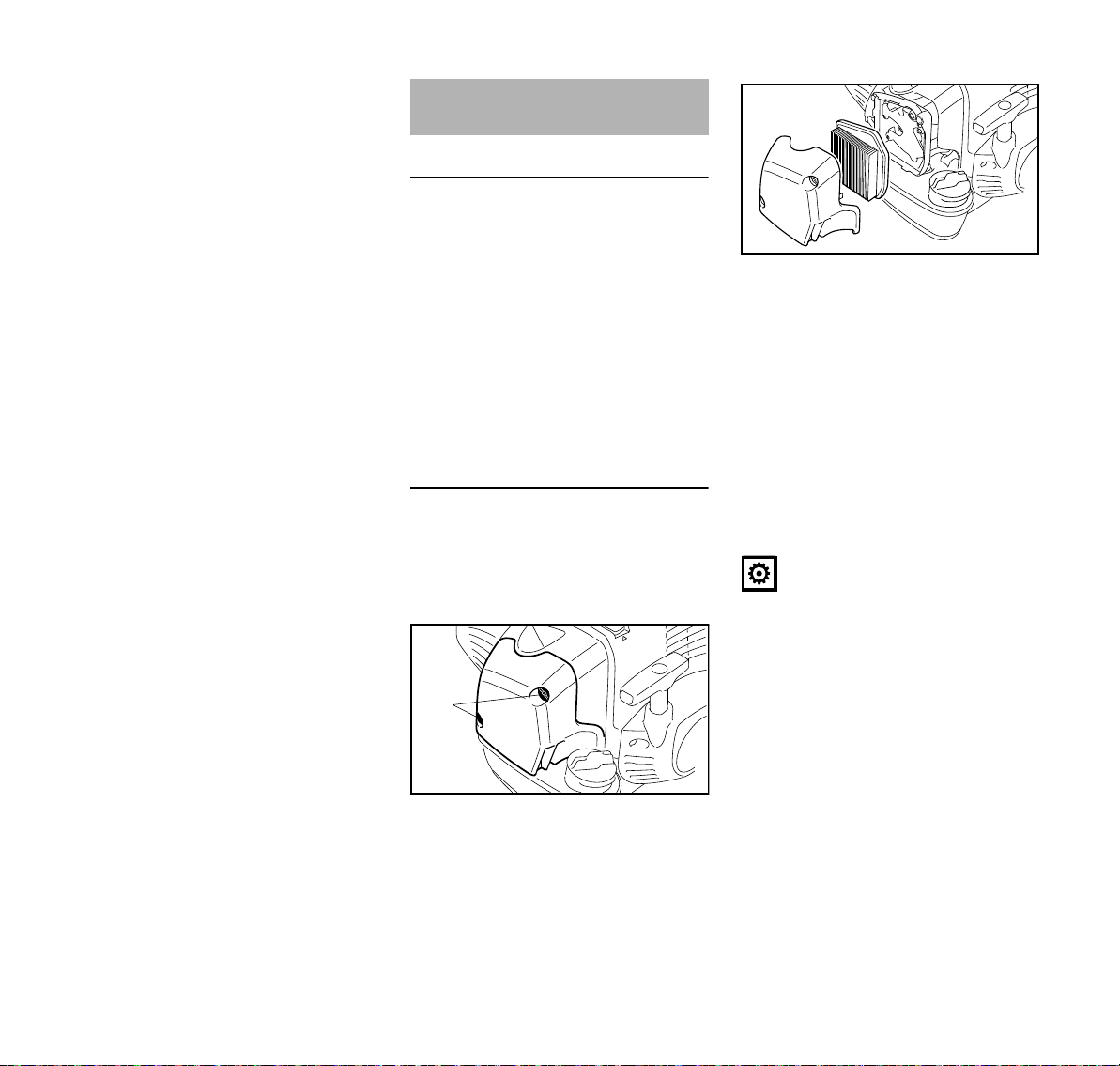
français
9926BA061 KN
1
3
9926BA062 KN
2
toute source d'inflammation. Pour une
assez longue période d'immobilisation –
voir « Rangement du dispositif » !
Filtre à air
Informations de base
Les intervalles de maintenance du filtre
sont très longs.
Ne pas enlever le couvercle de filtre et
ne pas remplacer le filtre à air tant que
l'on ne constate pas de perte de
puissance sensible.
Si le filtre à air est encrassé, la
puissance du moteur baisse, la
consommation de carburant augmente
et la mise en route du moteur devient
plus difficile.
Remplacement du filtre à air
Seulement si la puissance du moteur
baisse sensiblement
N Tourner le levier du volet de starter
dans la position } ;
N desserrer les vis de fixation (1) ;
N enlever le couvercle de filtre (2) ;
N nettoyer grossièrement la face
intérieure du couvercle de filtre et le
voisinage du filtre (3) ;
Le filtre (3) assure la filtration de l'air à
travers un élément filtrant en papier
plissé.
N enlever et contrôler le filtre (3) – le
remplacer en cas d'encrassement
ou d'endommagement du papier ou
du cadre de l'élément filtrant ;
N déballer le filtre neuf ;
AVIS
Avant sa mise en place, le filtre ne doit
être ni recourbé, ni plié, car il risquerait
d'être endommagé – ne pas utiliser un
filtre endommagé !
N mettre le filtre dans le boîtier de
filtre ;
N monter le couvercle du filtre.
Utiliser exclusivement des filtres à air de
haute qualité, pour protéger le moteur
contre la pénétration de poussière
abrasive.
STIHL recommande d'utiliser
exclusivement des filtres à air d'origine
STIHL. Le haut niveau de qualité de ces
pièces garantit un fonctionnement sans
FS 360 C
91
Page 94

français
dérangements, une grande longévité du
moteur et de très longs intervalles de
maintenance du filtre.
Élément filtrant pour l'utilisation en hiver
Pour l'entretien et la maintenance de
l'élément filtrant spécial pour l'utilisation
en hiver, voir le chapitre « Utilisation en
hiver ».
Gestion moteur M-Tronic
La régulation des émissions de
nuisances à l'échappement est assurée
par la définition des paramètres et la
configuration des composants du
moteur de base (par ex. carburation,
allumage, calage de l'allumage et de la
distribution),
Informations de base
La M-Tronic assure la régulation
électronique du débit de carburant et du
point d'allumage dans toutes les
conditions de fonctionnement.
Avec la M-Tronic, la mise en route du
moteur est plus facile et plus rapide.
Indépendamment des conditions
climatiques et des températures du
moteur, on procède à la mise en route
du moteur avec le levier de starter en
position de démarrage }. Après la
mise en route du moteur, on peut laisser
le levier de starter en position de
démarrage } jusqu'à ce que le moteur
tourne rond et ne risque plus de caler.
La M-Tronic garantit le rendement
optimal du moteur en toutes
circonstances, une excellente reprise et
une adaptation automatique en fonction
des variations des conditions de
fonctionnement.
C'est pourquoi aucune correction
manuelle du réglage du carburateur
n'est nécessaire – le carburateur ne
possède pas de vis de réglage.
Si, en cas de changement extrême des
conditions d'utilisation, le moteur ne
fonctionne plus parfaitement et n'atteint
plus sa puissance habituelle, il faut
s'adresser à un revendeur spécialisé.
STIHL recommande de faire effectuer
les opérations de maintenance et les
réparations exclusivement chez le
revendeur spécialisé STIHL.
92
FS 360 C
Page 95

français
2
1
9926BA016 KN
2
9926BA017 KN
3
2
9926BA018 KN
Utilisation en hiver
À des températures inférieures à +10 °C
(+50 °F)
Préchauffage du carburateur
Après la transposition d'un tiroir, en plus
de l'air froid, le moteur aspire de l'air
réchauffé en balayant le cylindre, ce qui
évite le givrage du carburateur.
Une flèche appliquée sur le capot (1)
indique la position du tiroir (2)
respectivement pour l'utilisation en été
et pour l'utilisation en hiver. Signification
des symboles :
– symbole « soleil » = utilisation en
été ;
– symbole « cristal de neige » =
utilisation en hiver
N Dévisser et enlever la vis (3) du
tiroir ;
N extraire le tiroir (2) du capot ;
N tourner le tiroir (2) de la position
d'été dans la position d'hiver et le
remettre en place ;
N visser la vis (3) dans le capot, à
travers le tiroir.
À des températures situées entre
+10 °C (+50 °F) et +20 °C (+70 °F)
Dans cette plage de températures, la
machine peut être normalement utilisée
avec le tiroir (2) en position d'été.
Transposer le tiroir suivant besoin.
À des températures supérieures à
+20 °C (+70 °F)
N Remettre impérativement le
tiroir (2) dans la position d'été.
AVIS
À des températures supérieures à
+20 °C (+70 °F), il ne faut pas travailler
avec le tiroir en position d'hiver, car des
dysfonctionnements du moteur
pourraient se produire par suite d'une
surchauffe !
À des températures inférieures à
-10 °C (+14 °F)
Pour des conditions hivernales
extrêmes, dans les situations
suivantes :
– températures inférieures à
-10 °C (+14 °F) ;
– neige poudreuse ou soulevée par le
vent ;
il est recommandé d'utiliser le « kit
plaque de recouvrement » livrable à titre
d'accessoire optionnel.
Deux « kits plaque de recouvrement »
différents, à utiliser suivant la version du
bouchon du réservoir, sont disponibles.
FS 360 C
93
Page 96

français
4
5
9926BA063 KN
2
1
9926BA020 KN
Les « kits plaque de recouvrement »
comprennent les pièces suivantes
nécessaires pour la transformation de la
machine :
4 plaque de recouvrement pour
masquer partiellement les fentes du
carter du lanceur ;
5 élément filtrant en tissu et matière
synthétique pour le filtre à air ;
– folio décrivant la transformation de
la machine.
En plus pour les machines avec
bouchon de réservoir à carburant à
ailette rabattable :
– joint torique pour le bouchon du
réservoir à carburant.
Après le montage du kit plaque de
recouvrement :
N placer le tiroir (2) en position d'hiver.
torique du « kit plaque de
recouvrement » monté sur le bouchon
du réservoir à carburant peut rester sur
la machine.
Suivant la température ambiante :
N placer le tiroir (2) en position d'été
ou d'hiver.
Nettoyage du filtre à air
N Desserrer les vis de fixation du
couvercle de filtre ;
N enlever le couvercle de filtre ;
N nettoyer grossièrement la face
intérieure du couvercle de filtre et le
voisinage du filtre (5) ;
N battre le filtre (5) ou le nettoyer à l'air
comprimé, de l'intérieur vers
l'extérieur ;
En cas d'encrassement persistant ou si
les saletés sont agglutinées dans le
tissu du filtre :
N laver le filtre dans une solution de
nettoyage propre et ininflammable
(par ex. de l'eau savonneuse
chaude) et le faire sécher.
Un filtre endommagé doit être remplacé.
Bougie
En cas de perte de puissance du
moteur, de difficultés de démarrage ou
de perturbations au ralenti : contrôler
tout d'abord la bougie.
Remplacer la bougie après env.
100 heures de fonctionnement – ou plus
tôt, si les électrodes sont
usées/corrodées.
Un mélange de carburant incorrect (trop
grand pourcentage d'huile moteur dans
l'essence), un filtre à air colmaté et des
conditions de fonctionnement
défavorables (utilisation fréquente avec
commande d'accélérateur à mi-course
etc.) causent une dégradation de l'état
de la bougie. Ces facteurs entraînent la
formation de dépôts sur l'extrémité de
l'isolateur, ce qui peut causer une
dégradation des performances.
Démontage de la bougie
À des températures supérieures à
-10 °C (+14 °F)
N Retransformer la machine et
remplacer les pièces du kit plaque
de recouvrement par les pièces
pour l'utilisation en été.
Remarque concernant les machines
munies d'un bouchon de réservoir à
carburant à ailette rabattable : le joint
94
N Tourner la vis (1) du capuchon (2)
jusqu'à ce que la tête de la vis
dépasse du capuchon (2) et que la
partie avant du capuchon puisse
être relevée ;
FS 360 C
Page 97

N soulever la partie avant du
3
9926BA021 KN
000BA039 KN
A
2
0000-GXX-1830-A0
3
1
capuchon (2) et la pousser vers
l'arrière pour défaire l'encliquetage ;
N enlever le capuchon ;
N débrancher le contact de câble
d'allumage de la bougie (3) ;
N dévisser la bougie.
Un mélange de carburant incorrect (trop
grand pourcentage d'huile moteur dans
l'essence), un filtre à air colmaté et des
conditions de fonctionnement
défavorables (utilisation fréquente avec
commande d'accélérateur à mi-course
etc.) causent une dégradation de l'état
de la bougie. Ces facteurs entraînent la
formation de dépôts sur l'extrémité de
l'isolateur, ce qui provoque des
perturbations du fonctionnement.
En cas de manque de puissance du
moteur, de difficultés de démarrage ou
de perturbations au ralenti : contrôler
tout d'abord la bougie.
N Démonter la bougie – voir chapitre
« Mise en route / arrêt du moteur ».
N Nettoyer la bougie encrassée.
N Contrôler l'écartement des
électrodes (A) et le rectifier si
nécessaire – voir « Caractéristiques
techniques ».
N Utiliser exclusivement une bougie
ayant la valeur thermique requise.
Éliminer les causes de l'encrassement
de la bougie :
N Trop d'huile dans le mélange.
N Filtre à air encrassé.
N Conditions de fonctionnement
défavorables, par ex. utilisation
avec commande d'accélérateur à
mi-course.
Remplacer la bougie après env.
100 heures de fonctionnement – ou p lus
tôt, si les électrodes sont fortement
usées.
français
AVERTISSEMENT
Afin de réduire le risque d'incendie et de
brûlures, utiliser exclusivement les
bougies autorisées par STIHL. Toujours
fermement presser le contact du câble
d'allumage (1) sur la borne de la
bougie (2).
Ne pas utiliser une bougie munie d'une
borne constituée d'un adaptateur SAE
démontable (3). Un tel système
risquerait de produire un arc électrique
qui pourrait enflammer des vapeurs de
carburant et causer un incendie. Cela
pourrait causer des dommages
matériels et des personnes pourraient
être grièvement blessées.
N Utiliser exclusivement une bougie
antiparasitée munie d'une borne
fixe, sans filetage.
FS 360 C
95
Page 98

français
4
3
2
9926BA022 KN
Montage de la bougie
N Visser la bougie ;
N emboîter fermement le contact de
câble d'allumage sur la bougie ;
N présenter le capuchon (1) sur le
capot, par l'arrière et en l'inclinant
légèrement, et enfoncer son
ergot (2) dans l'orifice (3) du capot ;
N basculer le capuchon en avant, sur
le capot, puis visser et serrer la
vis (4).
Fonctionnement du moteur Rangement
Si, après la maintenance du filtre à air et
le réglage correct du câble de
commande des gaz, le fonctionnement
du moteur n'est pas satisfaisant, ce
défaut peut aussi provenir du silencieux
d'échappement.
Demander au revendeur spécialisé de
contrôler si le silencieux n'est pas
encrassé (calaminé) !
STIHL recommande de faire effectuer
les opérations de maintenance et les
réparations exclusivement chez le
revendeur spécialisé STIHL.
Pour un arrêt de travail de 3 mois ou
plus,
N vider et nettoyer le réservoir à
carburant à un endroit bien aéré ;
N éliminer le carburant conformément
à la législation et aux prescriptions
pour la protection de
l'environnement ;
N mettre le moteur en marche et le
laisser tourner jusqu'à ce que le
carburateur soit vide, sinon les
membranes du carburateur
risqueraient de se coller !
N enlever l'outil de coupe, le nettoyer
et le contrôler. Traiter les outils de
coupe métalliques avec de l'huile de
protection ;
N nettoyer soigneusement la
machine ;
N conserver la machine à un endroit
sec et sûr – la ranger de telle sorte
qu'elle ne puisse pas être utilisée
sans autorisation (par ex. par des
enfants).
96
FS 360 C
Page 99

français
2
2
1
2
1
1
002BA042 KN
002BA406 KN
Affûtage des outils de coupe
métalliques
N En cas d'usure mi nim e, r éaff ûte r les
outils de coupe avec une lime
d'affûtage (accessoire optionnel) –
en cas d'usure prononcée ou
d'ébréchure, les réaffûter avec une
affûteuse ou les faire réaffûter par le
revendeur spécialisé – STIHL
recommande de s'adresser au
revendeur spécialisé STIHL ;
N affûter assez souvent, mais en
enlevant peu de matière : pour un
simple réaffûtage, il suffit
généralement de donner deux ou
trois coups de lime ;
D'autres instructions à suivre pour
l'affûtage sont imprimées sur
l'emballage de l'outil de coupe. C'est
pourquoi il faut conserver
précieusement l'emballage.
Équilibrage
N Après le 5
contrôler le balourd avec
l'équilibreuse STIHL (accessoire
optionnel) – au besoin, rééquilibrer
l'outil de coupe ou le faire
rééquilibrer par le revendeur
spécialisé – STIHL recommande de
s'adresser au revendeur spécialisé
STIHL.
e
réaffûtage, environ,
Entretien de la tête
faucheuse
Pose de la machine sur le sol
N Arrêter le moteur ;
N poser la machine de telle sorte que
la prise pour outil de coupe soit
orientée vers le haut.
Remplacement du fil de coupe
Avant de remplacer le fil de coupe, il faut
impérativement vérifier si la tête
faucheuse n'est pas usée.
N affûter uniformément les lames (1)
du couteau – ne pas modifier le
contour du corps de l'outil (2).
FS 360 C
AVERTISSEMENT
Si l'on constate des traces d'usure
prononcées, il faut remplacer la tête
faucheuse complète.
Ci-après, le fil de coupe est simplement
appelé « fil ».
La tête faucheuse est livrée avec un folio
illustré montrant la procédure à suivre
pour le remplacement des fils. C'est
pourquoi il faut précieusement
conserver ces instructions spécifiques à
cette tête faucheuse.
N Au besoin, démonter la tête
faucheuse.
97
Page 100

français
Ajustage du fil de coupe
STIHL AutoCut
N Le moteur étant en marche, tenir la
machine au-dessus d'une surface
de gazon – la tête faucheuse doit
tourner ;
N frapper la tête faucheuse sur le sol –
la bobine débite une certaine
longueur de fil de coupe et
l'extrémité du fil est rognée à la
longueur correcte par le couteau
monté sur le capot protecteur.
Chaque fois que l'on frappe la tête
faucheuse sur le sol, cela fait débiter
une certaine longueur de fil. C'est
pourquoi il faut surveiller le rendement
de coupe de la tête faucheuse au cours
du travail. Si l'on frappe trop souvent la
tête faucheuse sur le sol, des morceaux
de fil sont inutilement rognés par le
couteau.
La sortie automatique du fil n'est
toutefois possible que si les deux
extrémités du fil qui dépassent encore
atteignent une longueur minimale de
2,5 cm (1 po).
STIHL TrimCut
AVERTISSEMENT
Pour réajuster manuellement la
longueur du fil, il faut impérativement
arrêter le moteur – risque de blessure !
N Tirer le boîtier de la bobine vers le
haut – tourner dans le sens inverse
des aiguilles d'une montre –
exécuter env. 1/6 de tour – jusqu'à
la position d'encliquetage – puis le
laisser revenir sous l'effet du
ressort ;
N tirer sur les extrémités du fil pour les
faire sortir.
Répéter cette procédure, au besoin,
jusqu'à ce que les deux extrémités du fil
de coupe atteignent le couteau monté
sur le capot protecteur.
Un mouvement de rotation, d'un cran
d'encliquetage à l'autre, débite
env. 4 cm (1,5 po) de fil.
Remplacement du fil de coupe
STIHL PolyCut
À la place des couteaux, sur la tête
faucheuse PolyCut, on peut aussi
accrocher un brin de fil coupé à la
longueur requise.
STIHL DuroCut, STIHL PolyCut
AVERTISSEMENT
Pour recharger la tête faucheuse à la
main, il faut impérativement arrêter le
moteur – risque de blessure !
N Monter des brins de fil de la
longueur requise sur la tête
faucheuse, comme décrit sur le folio
joint.
Remplacement des couteaux
STIHL PolyCut
Avant de remplacer les couteaux de la
tête faucheuse, il faut impérativement
vérifier si la tête faucheuse n'est pas
usée.
AVERTISSEMENT
Si l'on constate des traces d'usure
prononcées, il faut remplacer la tête
faucheuse complète.
Ci-après, les couteaux de la tête
faucheuse sont simplement appelés
« couteaux ».
La tête faucheuse est livrée avec un folio
illustré montrant la procédure à suivre
pour le remplacement des couteaux.
C'est pourquoi il faut précieusement
conserver ces instructions spécifiques à
cette tête faucheuse.
AVERTISSEMENT
Pour recharger la tête faucheuse à la
main, il faut impérativement arrêter le
moteur – risque de blessure !
N Démonter la tête faucheuse ;
N remplacer les couteaux comme
indiqué sur la notice illustrée ;
N remonter la tête faucheuse.
98
FS 360 C
 Loading...