

Page 1
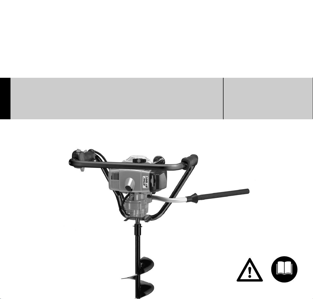
STIHL BT 120 C
STIH)
Instruction Manual
Manual de instrucciones
Warning!
For safe operation follow all safety
precautions in Instruction Manual - improper
use can cause serious injury.
Advertencia!
Para su seguridad durante el manejo de este
producto, siga siempre las precauciones de
seguridad dadas en el manual de
instrucciones - el uso indebido puede causar
lesiones graves.
Page 2

Contents
English / USA
Guide to Using this Manual .............. 2
Safety Precautions and
Working Techniques ......................... 3
Assembling the Machine ................ 10
Adjusting the Throttle Cable* .......... 11
Fuel ................................................ 11
Fueling ............................................ 12
Auger Brake ................................... 13
Fitting the Auger ............................. 14
Printing inks contain vegetable oils;
paper can be recycled.
Starting / Stopping the Engine ........ 14
Operating Instructions .................... 17
Releasing a Trapped Auger ............ 18
Cleaning the Air Filter ..................... 18
Motor Management ........................ 19
Adjusting the Carburetor ................ 19
Checking the Spark Plug ................ 21
Engine Running Behavior ............... 22
Lubricating the Gearbox ................. 23
Replacing Starter Rope
and Rewind Spring ......................... 23
Storing the Machine ........................ 25
Maintenance Chart ......................... 26
Parts and Controls .......................... 27
Specifications ................................. 28
Printed on chlorine-free paper.© ANDREAS STIHL AG & Co. KG, 2003
Maintenance and Repairs ............... 30
STIHL Incorporated Federal and
California Emission Control
Warranty Statement ........................ 31
Allow only persons who understand this
manual to operate your earth auger.
To receive maximum performance and
satisfaction from your STIHL earth
auger, it is important that you read and
understand
precautions
using your earth auger.
Contact your STIHL dealer or the STIHL
distributor for your area if you do not
understand any of the instructions in this
manual.
the maintenance and safety
, starting on page 3, before
!Warning!
Because an earth auger is a hightorque, gasoline-powered tool, some
special safety precautions must be
observed to reduce the risk of personal
injury.
Careless or improper use may cause
serious or even fatal injury.
* see "Guide to Using this Manual"
STIHl
0458 427 3021. M1. L3. T. Printed in Germany
1BT 120 C
Page 3

English / USA
Guide to Using this Manual
Pictograms
All the pictograms attached to the
machine are shown and explained in
this manual.
The operating and handling instructions
are supported by illustrations.
Symbols in text
The individual steps or procedures
described in the manual may be marked
in different ways:
: Step or procedure without direct
reference to an illustration.
Description of step or procedure that
refers directly to the illustration and
contains item numbers that appear in
the illustration.
Example:
Loosen the screw (1)
Lever (2) ...
In addition to the operating instructions,
this manual may contain paragraphs
that require your special attention. Such
paragraphs are marked with the
symbols described below:
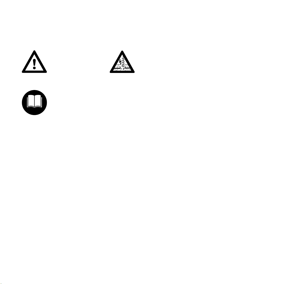
Warning where there is a risk of an
accident or personal injury or
serious damage to property.
Warning where there is a risk of
damaging the machine or individual
components.
Note or hint which is not essential
for using the machine, but may
improve the operator’s understanding of the situation and result
in better use of the machine.
Note or hint on correct procedure in
order to avoid damage to the
environment.
Equipment and features
This instruction manual refers to
several models with different
features. Components that are not
installed in all models and related
applications are marked thus
Such components are available as
special accessories from your
STIHL dealer.
*.
Engineering improvements
STIHL’s philosophy is to continually
improve all of its products. As a result,
engineering changes and improvements
are made from time to time. If the
operating characteristics or the
appearance of your machine differ from
those described in this manual, please
contact your STIHL dealer for
assistance.
Therefore, we cannot be responsible for
changes, modifications or
improvements not covered in this
manual.
2
BT 120 C
Page 4
Safety Precautions and Working Techniques
English / USA
Warning!
Because an earth auger is
a high-torque, gasolinepowered tool, some
special safety precautions
must be observed to
reduce the risk of
personal injury.
It is important that you
read, fully understand and
observe the following
safety precautions and
warnings. Read and
understand the owner's
manual and the safety instructions.
Careless or improper use of any earth
auger may cause serious or fatal injury.
!Warning!
Do not lend or rent your earth auger
without the owner's manual. Be sure that
anyone using your earth auger
understands the information contained
in this manual.
Have your STIHL dealer show you how
to operate your earth auger. Observe all
applicable local safety regulations,
standards and ordinances.
Danger!
Drilling into or contact with
electrical wires may
cause severe shock,
burns or death. See
"Working Conditions"
below.
!Warning!
Striking a hard object in the earth with
the turning auger and the resulting
slowing or stopping of the auger creates
reactive forces. The transfer of rotational
(reactive) forces can cause the auger
powerhead and handles to rotate
suddenly in a counterclockwise direction
and can result in loss of control or cause
the handle frame to hit the operator or
throw him to the ground, resulting in
serious injury.
!Warning!
Minors should never be allowed to use
an earth auger. Bystanders, especially
children, and animals should not be
allowed in the area where an earth
auger is in use. Never let the earth auger
run unattended.
See the appropriate section of your
owner's manual for a description of the
controls and function of the parts of your
earth auger.
Most of these safety precautions and
warnings apply to the use of all STIHL
earth augers. Different models may
have different parts and controls. See
the appropriate section of your owner's
manual for a description of the controls
and function of the parts of your model
earth auger.
Safe use of an earth auger involves
1. the operator
2. the earth auger
3. the use of the earth auger.
THE OPERATOR
Physical Condition
You must be in good physical condition
and mental health and not under the
influence of any substance (drugs,
alcohol, etc.) which might impair vision,
dexterity or judgment. Do not operate an
earth auger when you are fatigued. Be
alert - if you get tired while operating
your earth auger, take a break.
Tiredness may result in loss of control.
3BT 120 C
Page 5

English / USA
Working with any earth auger can be
strenuous. If you have any condition that
might be aggravated by strenuous work,
check with your doctor before operating
an earth auger.
!Warning!
Prolonged use of earth augers (or other
machines) exposing the operator to
vibrations may produce whitefinger
disease (Raynaud 's phenomenon) or
carpal tunnel syndrome. These
conditions reduce the hand's ability to
feel and regulate temperature, produce
numbness and burning sensations and
may cause nerve and circulation
damage and tissue necrosis.
All the factors which contribute to
whitefinger disease are not known, but
cold weather, smoking and diseases or
physical conditions that affect blood
vessels and blood transport, as well as
high vibration levels and long periods of
exposure to vibration are mentioned as
factors in the development of whitefinger
disease. In order to reduce the risk of
whitefinger disease and carpal tunnel
syndrome, please note the following:
– Wear gloves and keep your hands
warm.
– Maintain a firm grip at all times, but
do not squeeze the handles with
constant, excessive pressure.
– Take frequent breaks.
All the above-mentioned precautions do
not guarantee that you will not sustain
whitefinger disease or carpal tunnel
syndrome. Therefore, continual and
regular users should monitor closely the
condition of their hands and fingers. If
any of the above symptoms appear,
seek medical advice immediately.
!Warning!
The ignition system of your unit
produces an electromagnetic field of a
very low intensity. This field may interfere with some pacemakers. To reduce
the risk of serious or fatal injury, persons
with a pacemaker should consult their
physician and the pacemaker manufacturer before operating this tool.
Proper Clothing
!Warning!
To reduce the risk of injury, the operator
should wear proper protective apparel.
Clothing must be sturdy
and snug-fitting, but allow
complete freedom of
movement. Avoid loosefitting jackets, flared or
cuffed pants or anything
that could be drawn into the boring tool.
Wear overalls or long pants to protect
your legs. Secure hair so it is above
shoulder level. Do not wear shorts. Use
gloves when handling the earth auger.
To reduce the risk of
falling as a result of the
forces created by the
earth auger, good footing
is most important. Wear
sturdy footwear with
nonslip soles. Steel-toed safety boots
are recommended.
4
BT 120 C
Page 6
English / USA
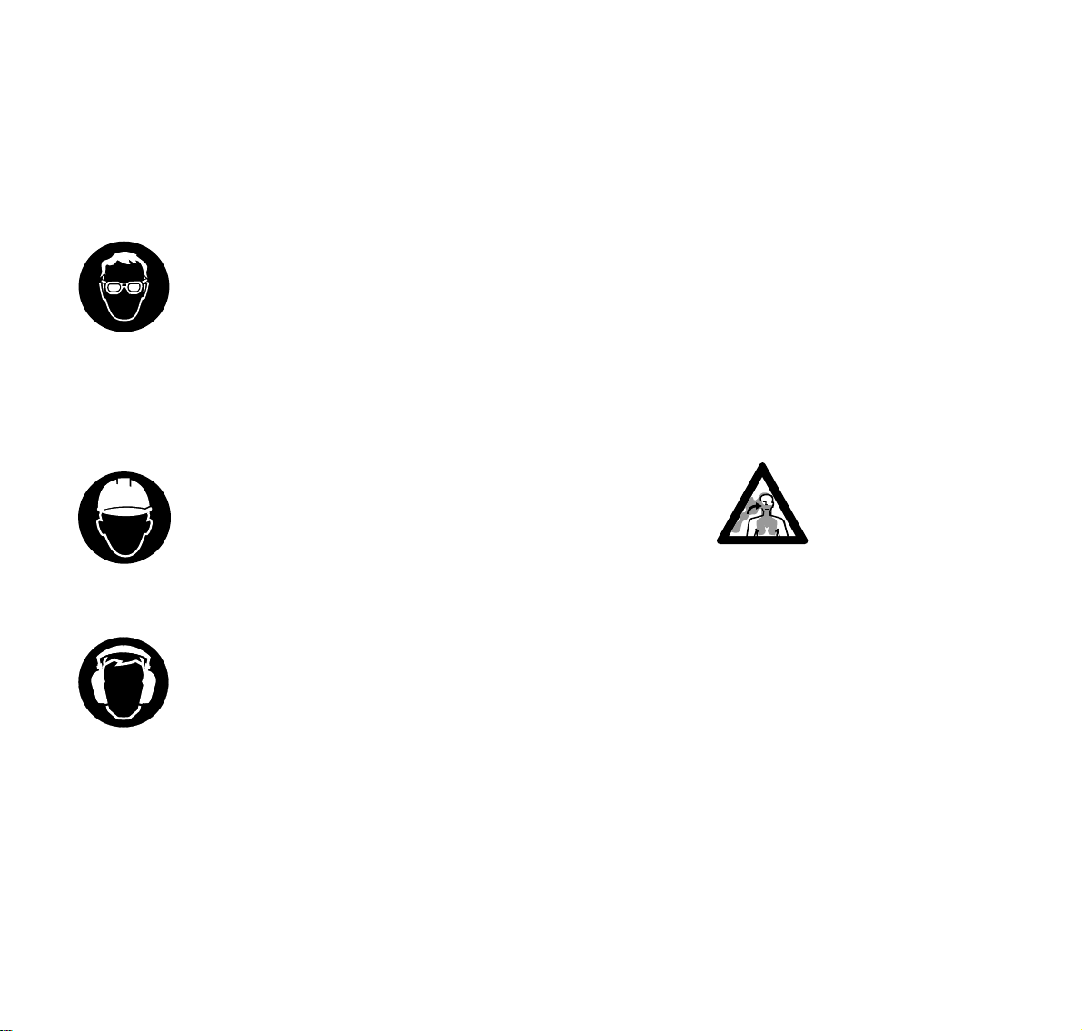
!Warning!
Thrown objects may ricochet and strike
the operator.
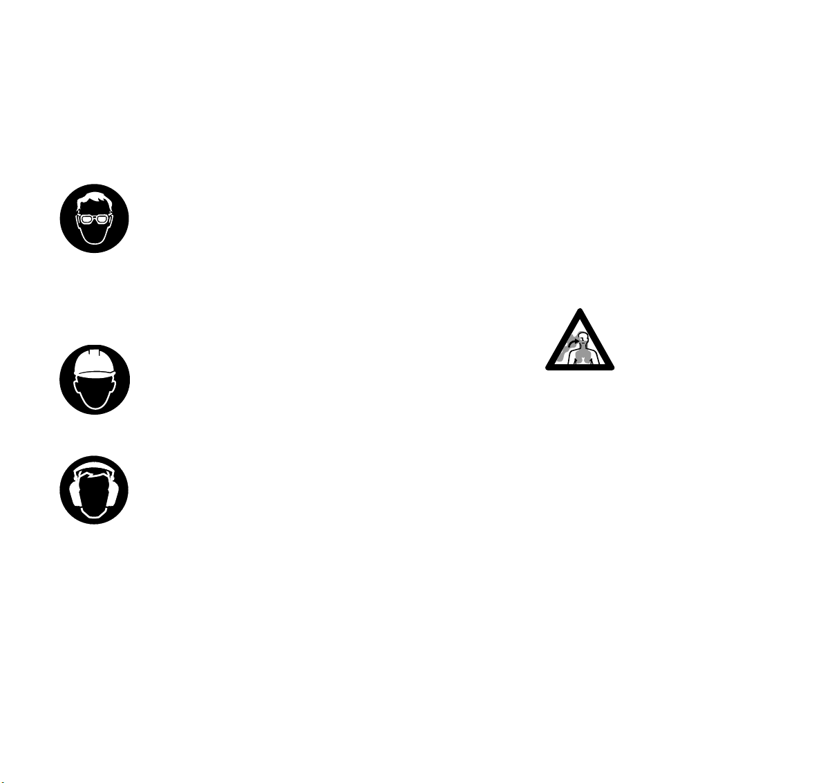
Therefore, to reduce the
risk of injury to your eyes
never operate an earth
auger unless wearing
goggles or properly fitted
protective glasses with
adequate top and side protection
complying with ANSI Z 87.1 (or your
applicable national standard).
!Warning!
Wear an approved safety
hard hat to protect your
head when there is a
danger of head injuries.
!Warning!
Earth auger noise may
damage your hearing.
Wear sound barriers (ear
plugs or ear mufflers) to
protect your hearing.
Continual and regular
users should have their hearing checked
regularly.
THE EARTH AUGER
For illustrations and definitions of the
earth auger parts see the chapters on
"Parts and Controls" and "Definitions".
Never modify an earth auger in any way.
Only drilling tools supplied by STIHL or
expressly approved by STIHL for use
with the specific STIHL earth auger
models are authorized. Use of other
drilling tools may increase the risk of
injury.
Other tools, adaptors or fittings may
mount to the auger, but may increase
the risk of injury or death.
THE USE OF THE EARTH AUGER
Transporting the earth auger
!Warning!
Always stop the engine before putting
the earth auger down or carrying it.
Carrying an earth auger with the engine
running is dangerous.
Accidental acceleration of the engine
can cause the drilling tool to rotate.
During operation, the powerhead muffler
and the material around it reach
extremely high temperatures. Avoid
setting down a hot unit onto dry,
flammable material, or touching the hot
muffler, you could receive serious burns.
By hand: Carry the earth auger with the
drilling tool pointing to the rear – with the
hot muffler away from your body.
Transporting by vehicle: When
transporting in a vehicle, properly secure
your power tool to prevent turnover, fuel
spillage and damage.
When the power tool is not in use, shut it
off and put it down so it cannot endanger
others.
!Warning!
Your earth auger
produces toxic exhaust
fumes as soon as the
combustion engine is
running. These gases
(e.g. carbon monoxide)
may be colorless and odorless. To
reduce the risk of serious or fatal injury
from breathing toxic fumes, never run
the earth auger indoors or in poorly
ventilated locations. Ensure proper
ventilation when working in trenches or
other confined areas.
5BT 120 C
Page 7
English / USA
Fuel Mix
Your STIHL earth auger uses an oilgasoline mixture for fuel (see the
chapter on "Fuel" in your owner's
manual).
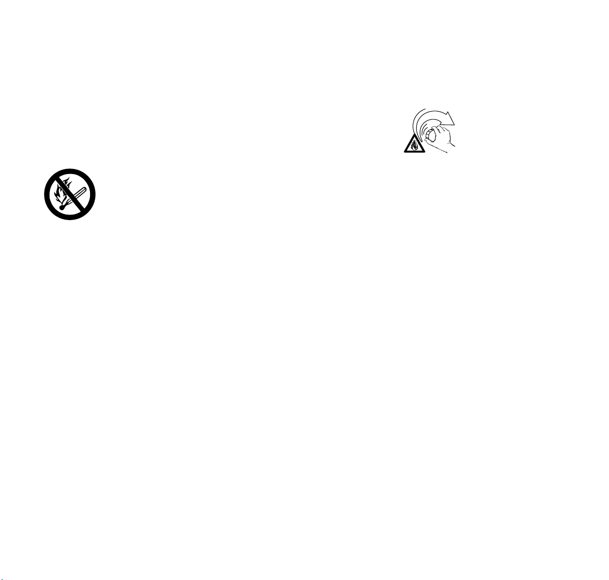
!Warning!
Gasoline is an extremely
flammable fuel. Use
extreme caution when
handling gasoline or fuel
mix. Do not smoke or
bring any fire or flame
near the fuel.
Fueling Instructions
!Warning!
Fuel your earth auger in well-ventilated
areas, outdoors. Always shut off the
engine and allow it to cool before
refueling. Gasoline vapor pressure may
build up inside the gas tank of a two
cycle engine depending on the fuel
used, the weather conditions, and the
venting system of the tank.
In order to reduce the risk of burns and
other personal injury from escaping gas
vapor and fumes, remove the fuel filler
cap on your earth auger carefully so as
to allow any pressure build-up in the
tank to release slowly. Never remove
fuel filler cap while engine is running.
Select bare ground for fueling and move
at least 10 feet (3 m) from the fueling
spot before starting the engine. Wipe off
any spilled fuel before starting your earth
auger and check for leakage.
!Warning!
Check for fuel leakage while refueling
and during operation. If fuel or oil
leakage is found, do not start or run the
engine until leak is fixed and spilled fuel
has been wiped away. Take care not to
get fuel on your clothing. If this happens,
change your clothing immediately.
!Warning!
Unit vibrations can cause
an improperly tightened
fuel filler cap to loosen or
come off and spill
quantities of fuel. In order
to reduce the risk of fuel
spillage and fire, tighten the fuel filler cap
by hand with as much force as possible.
Operating the earth auger
The earth auger should be operated by
one person.
To reduce the risk of injury from reactive
forces, the operator must have a firm
grip on the machine and a good foothold
before the throttle is opened to start the
earth auger.
Preparation for the use of the earth
auger
You should always inspect your earth
auger for proper condition and operation
before starting it. Pay special attention to
the throttle trigger, throttle trigger
interlock, stop switch, drilling tool and
auger brake.
6
BT 120 C
Page 8
English / USA
!Warning!
To reduce the risk of injury from a turning
drilling tool or from reactive forces, the
throttle trigger must move freely and
return immediately to the idle position
when it is released. Regular
maintenance is important in this respect.
Check the condition and the tightness of
the drilling tool.
Auger Brake
Your model earth auger is equipped with
an auger brake, which is designed to
reduce the risk of injury from reactive
forces by stopping the rotation of the
auger / powerhead when the brake
activating lever is engaged. It should
also be used during starting and when
unwinding a trapped auger. See the
chapter on "Auger brake" for information
on engagement of the brake.
!Warning!
Never operate your earth auger if it is
damaged, improperly adjusted or not
completely and securely assembled.
Injury could result.
Starting
For specific starting instructions, see the
appropriate section of your manual.
!Warning!
Your earth auger should be started only
when it is held steady by the operator.
When starting your earth auger, place it
on firm clean ground or other solid
surface in an open area. Maintain good
balance and secure footing.
!Warning!
To reduce the risk of loss of control, be
sure that the earth auger brake is
engaged before starting. Because the
engine speed at starting throttle is fast
enough for the clutch to drive the drilling
tool, the tool will turn unless the auger
brake is engaged.
427BA001 KN
!Warning!
When you pull the starter grip, don't
wrap the starter rope around your
hands. Do not allow the grip to snap
back, but guide the starter rope slowly to
permit the rope to rewind properly.
Failure to follow this procedure may
result in injury to hand or fingers and
may damage the starter mechanism.
Important Adjustments
!Warning!
At correct idle speed, the drilling tool
should not rotate. For directions to
adjust idle speed, see the appropriate
section of your owner's manual. To
reduce the risk of injury from a turning
drilling tool do not use an earth auger
with incorrect idle speed adjustment.
7BT 120 C
Page 9
English / USA
If you cannot set the correct idle speed,
have your STIHL dealer check your
earth auger and make proper
adjustments or repairs.
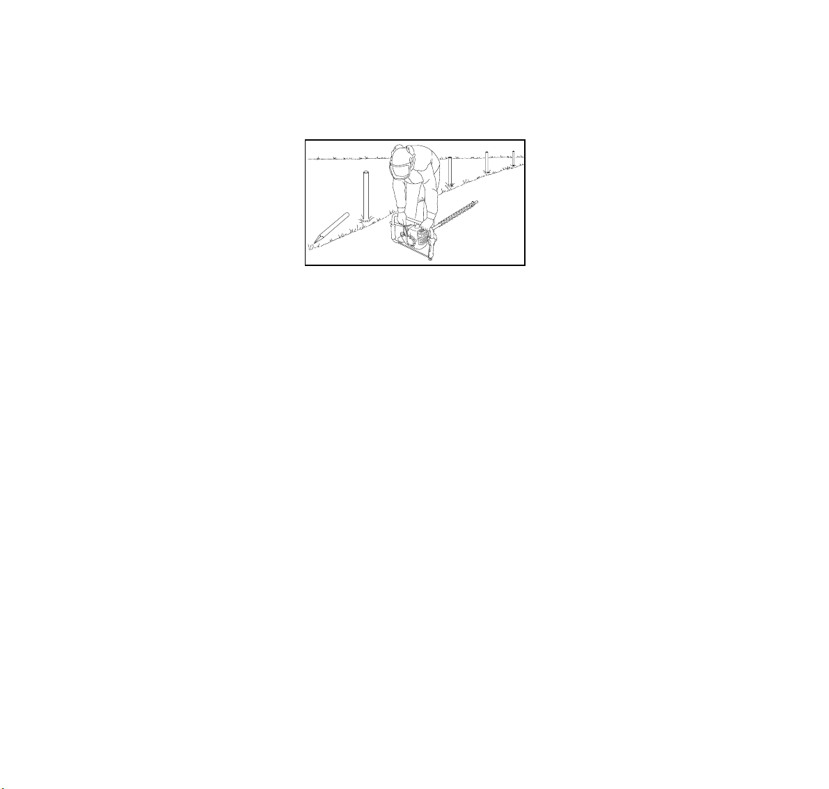
Working Conditions
Striking something hard in
the earth, such as a rock
or gravel, may cause the
drilling tool to slow down
suddenly or stop. In such
a situation, some or all of
the rotational force (reactive force) is
transferred to the powerhead and
handle frame of the earth auger which
can cause the auger powerhead and
handles to rotate suddenly in a
counterclockwise direction.
!Warning!
Work carefully in rocky ground or where
other solid objects may be present.
Keep throttle feed pressure to a
427BA002 KN
minimum. If you feel or hear the drilling
tool strike a solid object, release the
throttle trigger immediately and remove
the object before drilling is continued.
When drilling in heavy clay soil, bore
about 1/3 way and remove the auger
from the hole. Clean off auger then
continue in slow steps frequently
clearing drill.
!Warning!
You should hold your earth auger firmly
to control sudden jolts and reactive
forces. Be prepared to release the
throttle completely if the forces become
too great. If reactive forces are not
controlled, rotation of the handles may
result in severe jerking and loss of
control and may cause the handle frame
to strike you or throw you to the ground.
Your model earth auger is equipped with
an auger brake. If the auger hits
something it cannot drill through and the
powerhead begins to rotate so that the
auger brake activating lever strikes the
operator´s thigh and engages, the brake
is designed to stop the rotation of the
powerhead.
!Warning!
In order to reduce the risk of serious or
fatal injury from reactive forces, never
operate your earth auger without a
properly functioning auger brake.
If the auger becomes trapped in the
drillhole, turn off the engine immediately
and remove as descripted in the chapter
entitled "Removing a Trapped Auger".
8
BT 120 C
Page 10

English / USA
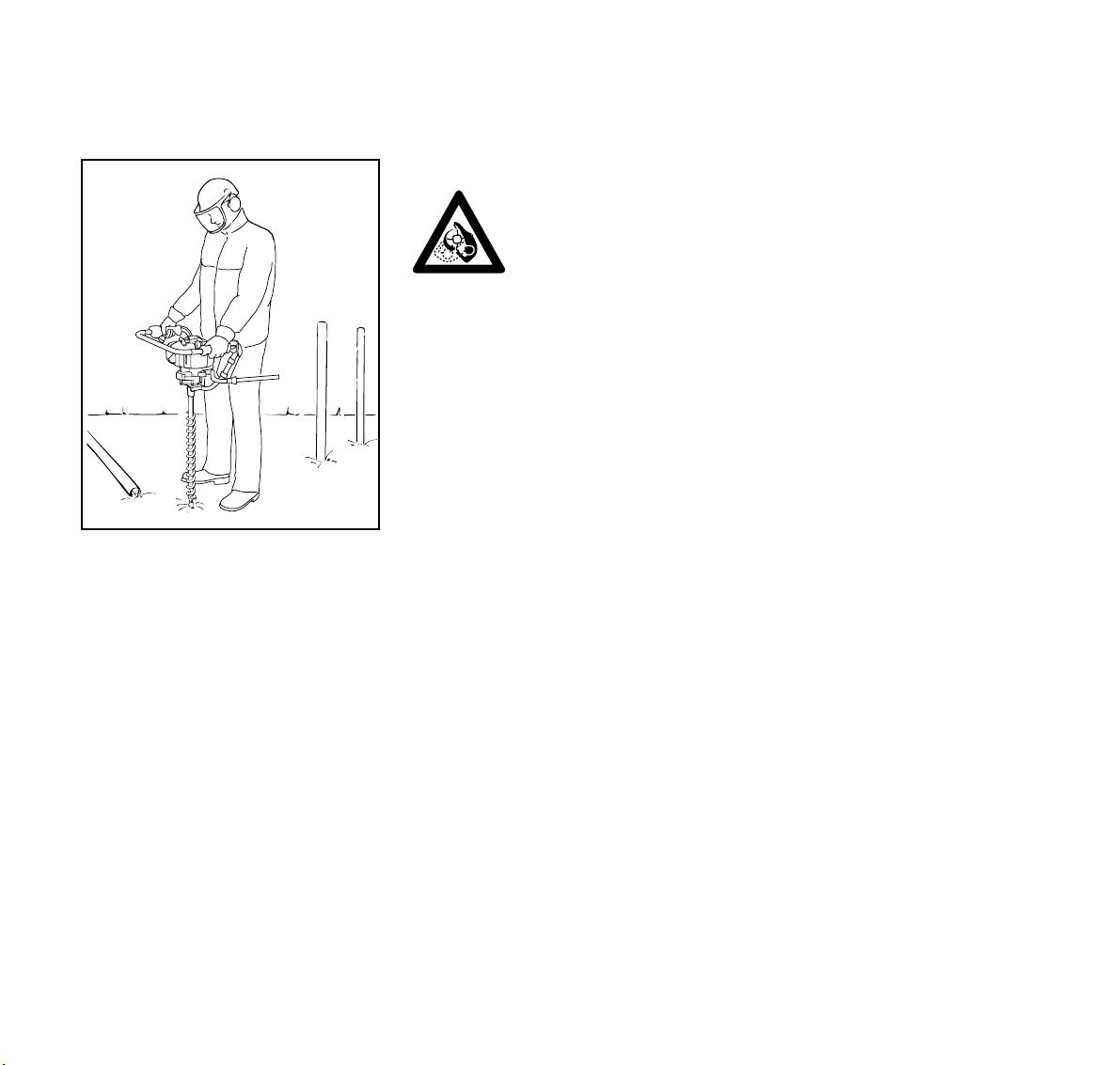
!Warning!
Operate and start your earth auger only
outdoors in a well ventilated area.
Operate the earth auger under good
visibility and daylight conditions only.
Work carefully. Always hold the earth
auger firmly with both hands. Wrap your
fingers tightly around the handles,
keeping the handles cradled between
your thumb and fingers. Keep your
hands in this position to have your earth
auger under control at all times. Make
sure your earth auger handles and grip
are in good condition and free of
moisture, pitch, oil or grease.
DANGER!
Contact with electrical
cables or wires can cause
serious injury or death as
a result of electrical
shock. This unit is not
insulated.
!Warning!
To reduce the risk of electrocution and
damage to property, always be alert for
underground pipes and cables and for
overhead wires. Before drilling, obtain
the necessary plans and permits.
Contact your local utility company or
your locator service, such as "Miss
Utility" or "One Call", for information as
to cable and pipe locations. Where
necessary, confirm actual location by
use of devices such as cable detectors
and/or by carefully dug trenches. Stay
clear of overhead electrical wires when
backing the drilling tool out of the hole. If
any portion of the machine strikes a
wire, it will cause electrical shock or
death.
!Warning!
To reduce the risk of falling, be careful
when carrying or operating the machine
in slippery conditions when the ground is
wet, icy or snow covered. Special care
must also be taken on embankments
and slopes.
Operating Instructions
!Warning!
To reduce the risk of injury, never touch
a rotating drilling tool or drilling spindle
with your hand or any part of your body.
It continues to rotate for a short period
after the throttle lever is released.
Always shut off the engine before putting
the machine down or transporting it over
a long distance.
When taking the drilling tool out of the
hole, lift the machine vertically so that
the tool comes out straight without
canting. Cover and clearly mark
boreholes, to prevent anyone from
stepping in a hole.
9BT 120 C
Page 11
English / USA
Assembling the Machine
Maintenance, Repair and Storing
Maintenance, replacement, or repair
of the emission control devices and
systems may be performed by any
nonroad engine repair establishment
or individual. However if you claim
warranty for a component which has
not been serviced or maintained
properly or if nonapproved
replacement parts were used, STIHL
may deny warranty.
Use only STIHL replacement parts for
maintenance and repair. Use of parts
manufactured by others may damage
your earth auger or cause serious injury.
Follow the maintenance and repair
instructions in the appropriate section of
your owner's manual.
!Warning!
Always stop the engine before doing any
maintenance or repair work.
Do not attempt any maintenance or
repair work not described in your
owner's manual. Have such work
performed at your STIHL servicing
dealer only.
!Warning!
Check condition of drilling tool at regular
short intervals. If behavior of tool
changes, check immediately for
tightness or any signs of cracks in
particular.
!Warning!
Replace damaged drilling tools
immediately, even if they have only
superficial cracks. Never attempt to
repair damaged drilling tools.
Check fuel filler cap for leaks at regular
intervals. Use the specified spark plug
and make sure it and the ignition lead
are always in good condition. Keep
spark plug and wire connections tight
and clean.
!Warning!
A worn or damaged muffler is a fire
hazard and may cause hearing loss.
Check to see that the muffler is in good
condition. The earth auger must not be
operated if the muffler is not functioning
properly or has been removed. Never
touch a hot muffler or burn will result. In
order to reduce the risk of fire, do not
modify or remove any part of the muffler.
Tighten all nuts, bolts and screws except
the carburetor adjustment screws after
each use.
For any maintenance please refer to the
maintenance chart and to the warranty
statement near the end of this manual.
Store earth auger in a high or locked
place, away from children, and empty
the fuel tank before storing for longer
than a few days.
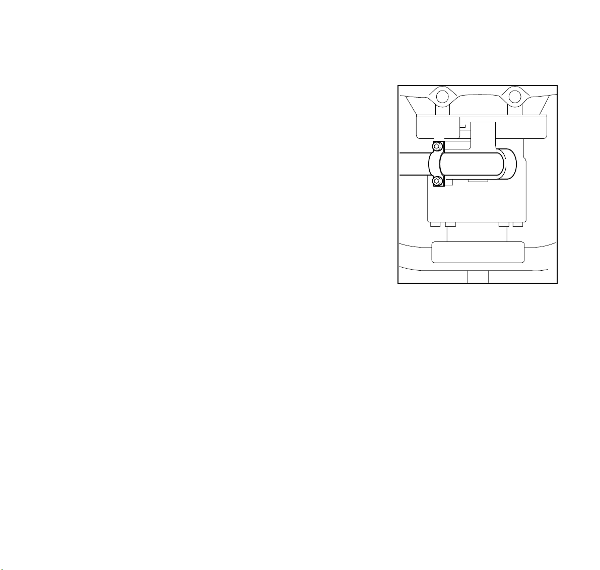
3
2
1
3
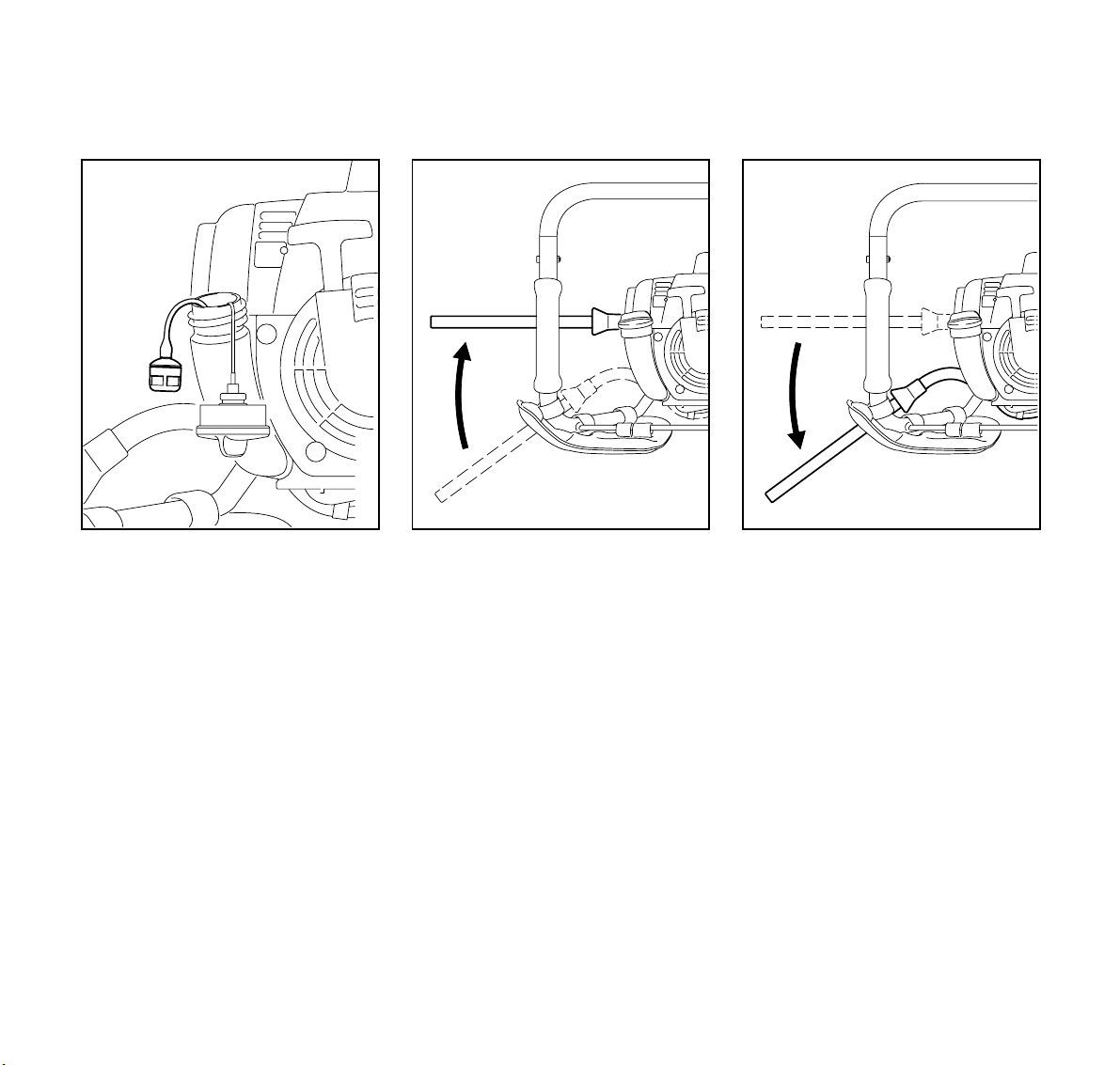
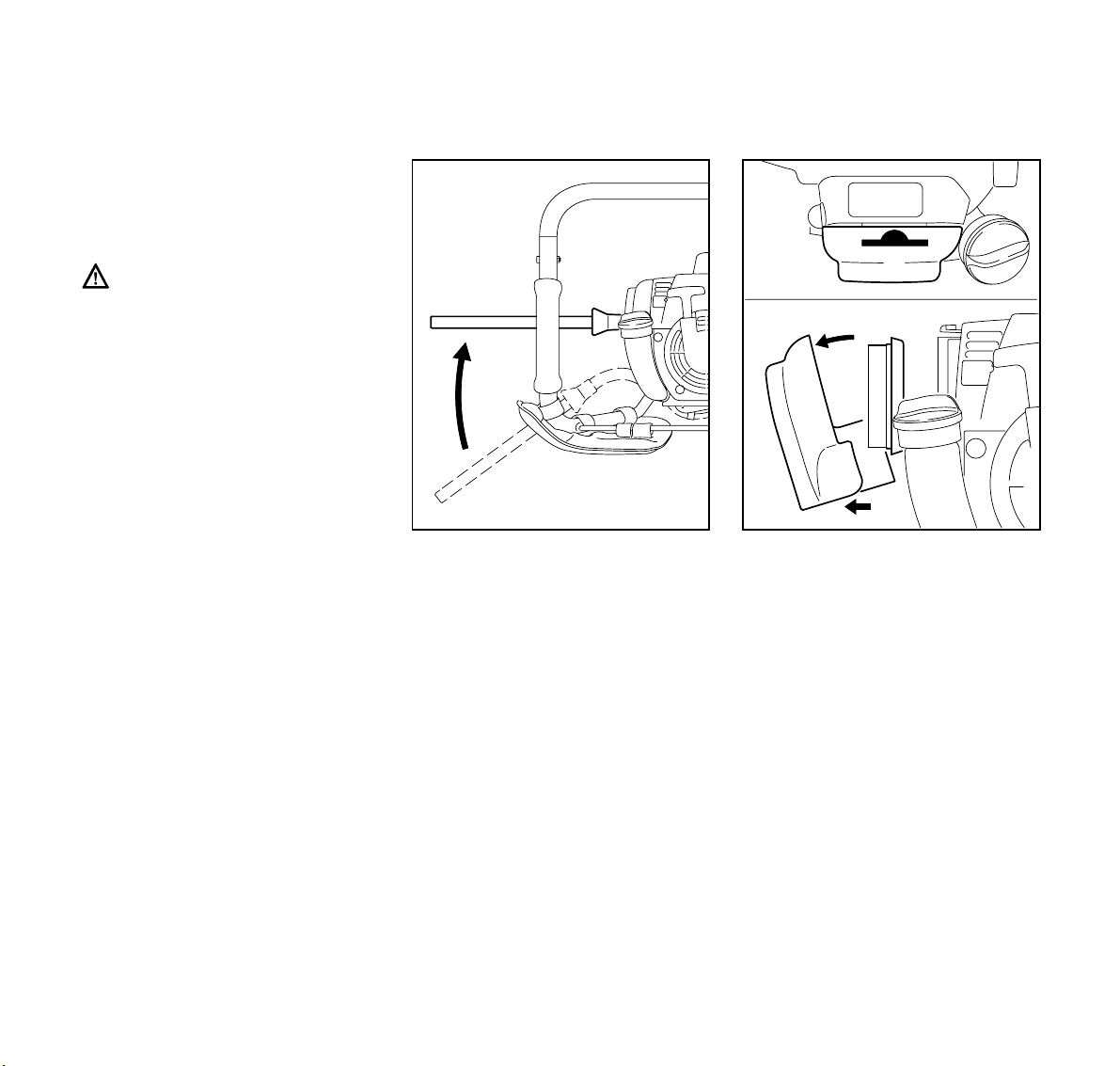
Mounting activating lever for
auger brake
: Place the activating lever (1) in the
clamp.
: Position the clamp (2) on the
activating lever.
: Insert mounting screws (3) and
tighten them down firmly.
Throttle cable adjustment*
On control handles with slide*:
: Go to chapter on "Adjusting the
Throttle Cable".
424BA005
10
* see "Guide to Using this Manual"
BT 120 C
Page 12

English / USA
Adjusting the Throttle Cable*
A properly adjusted throttle cable is
the precondition for correct
operation in the full throttle, starting
throttle and idle positions.
Adjust the throttle cable only after
the unit is fully assembled.
: Use a suitable tool to push the slide
to the bottom of the slot (see
illustration).
1
2
: Press down the trigger interlock (1)
and squeeze the throttle trigger (2)
(full throttle) – this sets the throttle
cable correctly.
002BA163 KN
Fuel
This engine is certified to operate on
unleaded gasoline and the STIHL twostroke engine oil at a mix ratio of 50:1.
Your two-stroke engine requires a
mixture of high-quality gasoline and
quality two-stroke air cooled engine oil.
Use mid-grade unleaded gasoline with a
002BA161 KN
minimum octane rating of 89 (R+M/2). If
the octane rating of the mid-grade
gasoline in your area is lower, use
premium unleaded fuel.
Fuel with a lower octane rating may
increase engine temperatures. This, in
turn, increases the risk of piston seizure
and damage to the engine.
The chemical composition of the fuel is
also important. Some fuel additives not
only detrimentally affect elastomers
(carburetor diaphragms, oil seals, fuel
lines, etc.), but magnesium castings and
catalytic converters as well. This could
cause running problems or even
damage the engine. For this reason
STIHL recommends that you use only
nationally recognized high-quality
unleaded gasoline!
* see "Guide to Using this Manual"
11BT 120 C
Page 13
English / USA
Fueling
Use only STIHL two-stroke engine oil or
equivalent high-quality two-stroke
engine oils that are designed for use
only in air cooled two-cycle engines.
We recommend STIHL 50:1 two-stroke
engine oil since it is specially formulated
for use in STlHL engines.
Do not use BIA or TCW rated (twostroke water cooled) mix oils or other
mix oils that state they are for use in both
water cooled and air cooled engines
(e.g., outboard motors, snowmobiles,
chainsaws, mopeds, etc.).
Take care when handling gasoline.
Avoid direct contact with the skin and
avoid inhaling fuel vapor. When filling at
the pump, first remove the canister from
your vehicle and place the canister on
the ground before filling. Do not fill fuel
canisters that are sitting in or on a
vehicle.
The canister should be kept tightly
closed in order to avoid any moisture
getting into the mixture.
The machine‘s fuel tank and the canister
in which fuel mix is stored should be
cleaned as necessary.
Fuel mix ages
Only mix sufficient fuel for a few days
work, not to exceed 3 months of storage.
Store in approved fuel-canisters only.
When mixing, pour oil into the canister
first, and then add gasoline. Close the
canister and shake it vigorously by hand
to ensure proper mixing of the oil with
the fuel.
Gasoline
Oil (STIHL 50:1 or
equivalent high-quality oils)
US gal. US fl.oz
12.6
2 1/2 6.4
5 12.8
Dispose of empty mixing-oil canisters
only at authorized disposal locations.
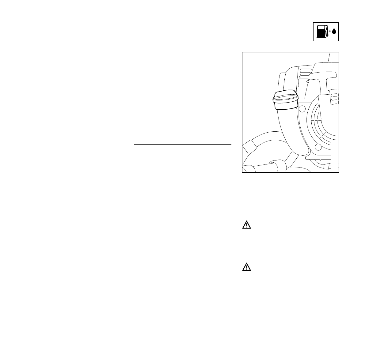
427BA003 KN
Before fueling, clean the filler cap and
the area around it to ensure that no dirt
falls into the tank.
Always thoroughly shake the mixture in
the can before fueling your machine.
In order to reduce the risk of burns
or other personal injury from
escaping gas vapor and fumes,
remove the fuel filler cap carefully
so as to allow any pressure build-up
in the tank to release slowly..
After fueling, tighten down the filler
cap by hand as securely as
possible.
12
BT 120 C
Page 14
Auger Brake
427BA004 KN
A
427BA005 KN
English / USA
B
427BA006 KN
Change the fuel pickup body every
year.
Before storing your machine for a long
period, drain and clean the fuel tank.
Run the engine until the carburetor is
dry.
Engaging the auger brake
: Move the activating lever to
position A engage the brake
– when starting the engine
– at idle speed
– to unwind a trapped auger
If the auger snags on an obstacle in the
hole (e.g. roots or stones) the earth
auger will rotate counterclockwise - the
activating lever is pressed against the
operator's thigh and thus engages the
auger brake.
Disengaging the auger brake
: Move the activating lever to
position B.
13BT 120 C
Page 15
English / USA
4
Check operation of auger brake
Before you start work:
With the engine running at idle speed,
engage the auger brake and then open
the throttle wide for no more than 3
seconds – the auger must not rotate.
The auger brake is subject to normal
wear and tear.
Check that it is operating properly before
you start work. If the auger brake fails,
have it repaired immediately by your
STIHL dealer.
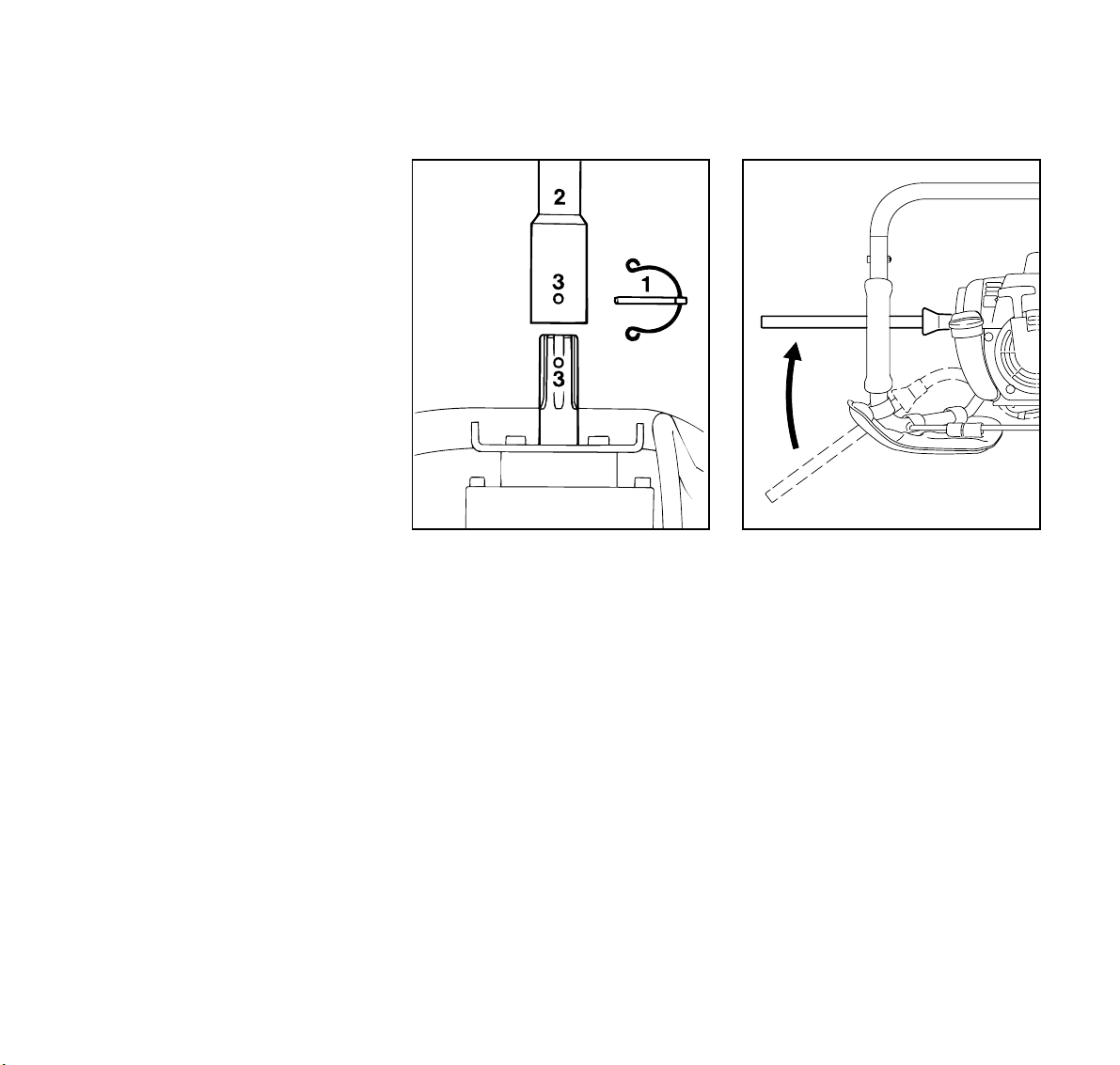
Fitting the Auger
: Shut off the engine. Put the earth
auger on the ground so that the
drilling spindle faces up.
: Engage the auger brake.
: Pull retaining pin (1) out of the
auger's shank.
: Push the auger (2) onto the drilling
spindle so that the holes (3) line up.
: Push retaining pin into the hole.
: Spring clip on retaining pin must fit
snugly around auger's shank.
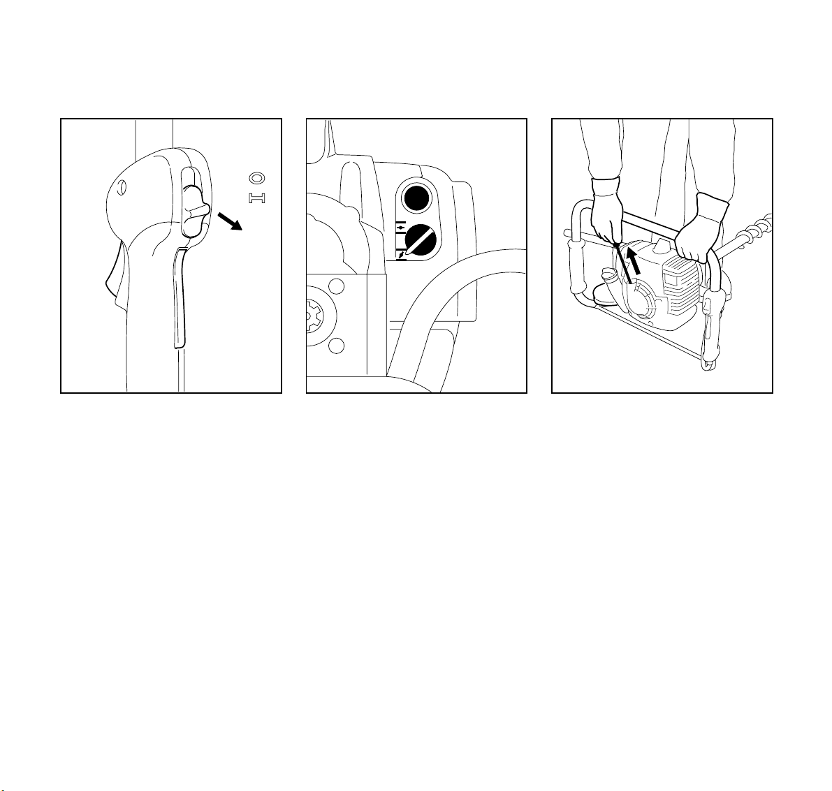
Starting / Stopping the Engine
A
24BA006
: Observe safety precautions – see
chapter on "Safety Precautions".
Engage auger brake
: Move the activating lever to
position A.
427BA005 KN
14
BT 120 C
Page 16
English / USA
3
START
2
1
Starting
: Press down the throttle trigger
interlock (1), squeeze the throttle
trigger (2) and hold them in that
position.
: Move the slide control (3) to START
and hold it there.
: Now release the throttle trigger,
slide control and throttle trigger
interlock in that order. This is the
starting throttle position.
5
4
392BA027 KN
: Set the choke knob (4):
To g if engine is cold.
To e if engine is warm.
(also use this setting if the engine
has been running but is still cold)
: Press the fuel pump bulb (5) at least
five times.
427BA007 KN
: Place the machine on the ground so
that it is secure.
: Put your right foot in the handle
frame and press down, left hand on
the handle frame.
: Pull the starter grip slowly with your
right hand until you feel it engage –
and then give it a brisk strong pull.
Do not pull out starter rope to full
length – it might break.
: Do not let the starter grip snap back
– guide it back into the housing so
that the starter rope can rewind
properly.
: Continue cranking until the engine
runs.
427BA008 KN
15BT 120 C
Page 17
English / USA
3
2
When the engine begins to fire:
: Turn the choke knob to e and
continue cranking.
As soon as the engine runs:
: Blip the throttle trigger (2) –
the slide control (3) moves to the run
position # and the engine settles
down to idle speed.
.
Since the auger brake is still
engaged, the engine must be
returned to idle speed immediately
– or the clutch might otherwise be
damaged.
START
392BA028 KN
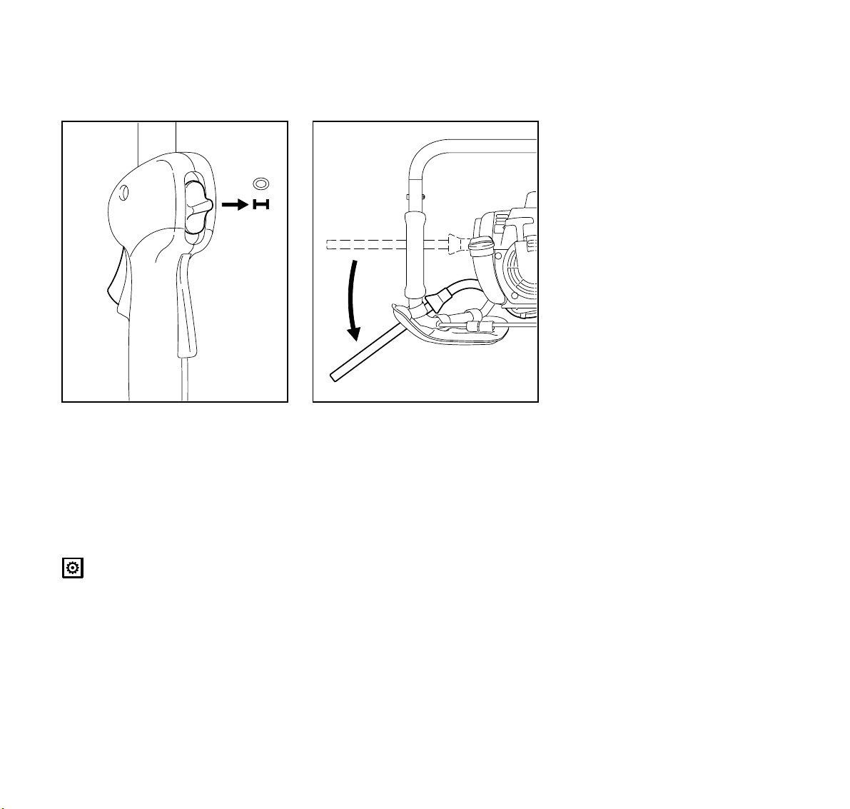
B
: Stand the unit on the tip of the
auger.
: Disengage the auger brake by
moving the activating lever to
position B. Your earth auger is now
ready for operation.
Make sure the carburetor is
correctly adjusted – the auger must
not rotate when the engine is idling.
To shut down the engine:
: Push the slide control in direction of
c to $
At very low outside temperatures:
Allow engine to warm up
As soon as the engine runs:
: Blip the throttle trigger to disengage
the starting throttle position – the
slide control moves to the normal
run position # and the engine
returns to idle speed.
: Open throttle slightly – warm up the
engine for a short period.
If the engine does not start:
If you did not turn the choke knob to e
quickly enough after the engine began to
427BA006 KN
fire, the combustion chamber has
flooded.
: Turn the choke knob to e
: Set the slide control, trigger
interlock and throttle trigger to the
starting throttle position.
: Start the engine – pull the starter
rope briskly – 10 to 20 pulls may be
necessary.
If the engine still does not start:
: Push the slide control in direction of
c to $
16
BT 120 C
Page 18

English / USA
Operating Instructions
1
: Pull off the spark plug boot (1).
: Unscrew and dry off the spark plug.
: Open the throttle wide.
: Pull the starter rope several times
to clear the combustion chamber.
: Fit the spark plug and connect the
spark plug boot – press it down
firmly.
: Move the slide control to START.
: Move the choke knob to e even if
the engine is cold.
: Now start the engine.
Throttle cable adjustment
: Check adjustment of throttle cable –
see chapter on "Adjusting the
Throttle Cable".
If tank has been run completely dry
and then refilled:
: Press the fuel pump bulb at least
427BA009 KN
fives times.
: Now start the engine.
During Break-in Period
A factory new machine should not be run
at high revs (full throttle off load) for the
first three tank fillings. This avoids
unnecessary high loads during the
break-in period. As all moving parts
have to bed in during the break-in
period, the frictional resistances in the
engine are greater during this period.
The engine develops its maximum
power after about 5 to 15 tank fillings.
During Operation
After a long period of full-throttle
operation, allow engine to run for a while
at idle speed so that the heat in the
engine can be dissipated by the flow of
cooling air. This protects enginemounted components (ignition,
carburetor) from thermal overload.
After Finishing Work
Wait for the engine to cool down. Drain
the fuel Kraftstofftank and store the
machine in a dry place. Check the
tightness of all accessible screws and
nuts (not adjusting screws) at regular
regulars and retighten as necessary.
17BT 120 C
Page 19
English / USA
Working with Shaft Extension
(special accessory)
Do not fit the shaft extension until the full
length of the auger is in the hole.
Starting a hole with the shaft
extension fitted increases the risk of
personal injury because the unit is
then at chest height and cannot be
kept properly under control.
For the same reason the shaft
extension must be removed before
the auger is pulled out of the hole.
Releasing a Trapped Auger
A
If the auger jams in the drill hole - shut off
the engine immediately.
: Move the slide control in direction of
c to $
: Engage the auger brake by moving
the activating lever to position A.
: Now rotate the whole machine to
the left – counterclockwise – to
unwind the auger from the ground.
Cleaning the Air Filter
1
3
2
427BA005 KN
If there is a noticeable loss of
engine power
: Turn choke knob to g
: Press in the tab (1).
: Remove the filter cover (2).
: Clean away loose dirt from inside of
filter cover and around the filter.
: Remove the filter element (3) and
check it – if it is dirty or damaged, fit
a new element.
: Fit the flter element in the filter
cover.
: Push the filter cover into position.
250BA022 KN
18
BT 120 C
Page 20

Motor Management Adjusting the Carburetor
Carburetor with LD Screw
English / USA
Exhaust emissions are controlled by the
design of the fundamental engine
parameters and components (e.g.
carburation, ignition, timing and valve or
port timing) without the addition of any
major hardware.
General Information
Your carburetor comes from the factory
with a standard setting.
This setting provides an optimum fuel-air
mixture under most operating
conditions.
Standard Setting
: Shut down the engine.
: Remove the auger from the
machine.
: Check air filter and clean or replace
as necessary.
: Check that the throttle cable is
properly adjusted and readjust if
necessary – see chapter on
"Adjusting the Throttle Cable".
+
LD
-
: Carefully screw the idle speed
screw (LD) down onto its seat
counterclockwise (left-hand thread).
Then open it two turns clockwise.
Adjusting Idle Speed
: Carry out standard setting.
: Start and warm up the engine.
250BA021 KN
19BT 120 C
Page 21

English / USA
Carburetor with H, L and LA
Screws
Engine stops while idling
: Turn the idle speed screw (LD)
slowly clockwise until the engine
runs smoothly – the drilling spindle
must not rotate.
Drilling spindle rotates when engine
is idling
: Turn the idle speed screw (LD)
counterclockwise until the drilling
spindle stops rotating – then turn the
screw about another one full turn in
the same direction from that
position.
Erratic idling behavior, poor
acceleration
: Turn the idle speed screw (LD)
slowly counterclockwise no more
than one half turn.
General Information
Your carburetor comes from the factory
with a standard setting.
This setting provides an optimum fuel-air
mixture under most operating
conditions.
With this carburetor it is only possible to
adjust the high speed screw within fine
limits.
Standard Setting
: Shut down the engine.
: Remove the auger from the
machine.
: Check air filter and clean or replace
as necessary.
: Check that the throttle cable is
properly adjusted and readjust if
necessary – see chapter on
"Adjusting the Throttle Cable".
L
H
1
LA
: Turn the high speed screw (H)
counterclockwise as far as stop
– max.
: Carefully turn the low speed
screw (L) down onto its seat
clockwise. Then open it one turn
counterclockwise.
: Start and warm up the engine.
: Adjust idle speed with the idle speed
screw (LA) so that the drilling
spindle does not rotate.
3
/4 turn
250BA039 KN
20
BT 120 C
Page 22

English / USA
Checking the Spark Plug
Adjusting Idle Speed
Engine stops while idling
: Standardeinstellung an der
Leerlaufstellschraube (L)
vornehmen
: Turn the idle speed screw (LA)
clockwise until the engine runs
smoothly – the drilling spindle must
not rotate.
Drilling spindle rotates when engine
is idling
: Turn the idle speed screw (LA)
counterclockwise until the drilling
spindle stops rotating – then turn the
screw about another half to one full
turn in the same direction from that
position.
Erratic idling behavior, poor
acceleration
: Carry out standard setting with the
low speed screw (L).
Idle setting too lean:
: Turn the low speed screw (L)
counterclockwise until the engine
runs and accelerates smoothly.
It is usually necessary to change the
setting of the idle speed screw (LA)
after every correction to the low speed
screw (L).
Fine tuning the carburetor for
operation at high altitude
A slight correction may be necessary if
the engine does not run satisfactorily:
: Check the standard setting.
: Warm up the engine.
: Turn the high speed screw (H)
clockwise (leaner).
000BA002 KN
Wrong fuel mix (too much engine oil in
the gasoline), a dirty air filter and
unfavorable running conditions (mostly
at part throttle etc.) affect the condition of
the spark plug. These factors cause
deposits to form on the insulator nose
which may result in trouble in operation.
21BT 120 C
Page 23

English / USA
Engine Running Behavior
If engine is down on power, difficult to
start or runs poorly at idling speed, first
check the spark plug.
: Remove spark plug as described
in chapter "Starting / Stopping the
Engine".
: Clean dirty spark plug.
: Check the electrode gap (A) and
readjust if necessary – see
"Specifications".
: Use only resistor type spark plugs
of the approved range.
Rectify problems which have caused
fouling of spark plug:
: Too much oil in fuel mix.
: Dirty air filter.
: Unfavorable running conditions,
e.g. operating at part load.
Fit a new spark plug after approx.
100 operating hours
or earlier if the electrodes are badly
eroded.
2
1
To reduce the risk of fire and burn
injury, use only spark plugs
authorized by STIHL. Always press
spark plug boot (2) snugly onto
terminal (1) of the proper size.
(Note: If terminal has detachable
SAE adapter nut, it must be
attached.) A loose connection
between spark plug boot and
ignition wire connector in the boot
may create arcing that could ignite
combustible fumes and cause a fire.
If engine running behavior is
unsatisfactory even though the air filter
is clean and the carburetor properly
adjusted, the cause may be in the
muffler.
Have the muffler checked for
contamination (coking) by a STIHL
dealer.
002BA071 KN
22
BT 120 C
Page 24

English / USA
Lubricating the Gearbox
1
Check grease level after about every 50
hours of operation:
: Unscrew the filler plug (1). If no
grease can be seen on the inside of
the filler plug, refill the gearbox.
2
424BA020
: Apply the tube (2) of STIHL gear
lubricant to the filler hole.
: Squeeze 1/4 oz (5-10 g) grease into
the gearbox.
Do not not over-fill the gearbox.
: Refit the filler plug and tighten it
down firmly.
Replacing Starter Rope and Rewind Spring
1
1
1
2
3
4
424BA021
Replacing a Broken Starter Rope
The rewind spring may pop out and
uncoil during this operation. Take
care to avoid injury.
: Remove the screws (1).
: Lift away the fan housing.
: Remove the spring clip (2).
: Carefully remove the rope rotor with
washer (3) and pawl (4).
1
256BA075 KN
256BA032 KN
23BT 120 C
Page 25

English / USA
5
7
6
256BA034 KN
: Ease the cap (5) out of the starter
grip.
: Remove remaining rope from the
rotor and grip.
: Tie a simple overhand knot in the
new rope – see “Specifications” –
and then thread it through the top of
the grip and the rope bush (6).
: Refit the cap in the grip.
2
3
4
256BA033 KN
: Thread the rope through the rotor
and secure it with a simple
overhand knot.
: Coat rope rotor bearing bore with
non-resinous oil – see "Special
Accessories".
: Slip rotor over starter post – turn it
back and forth to engage anchor
loop of rewind spring.
: Refit the pawl (4).
: Fit the washer (3).
: Install spring clip (2) on starter post
and engage it on the pawl's peg –
the spring clip must point clockwise.
7
256BA032 KN
Tensioning the Rewind Spring
: Make a loop in the unwound
starter rope and use it to turn
the rope rotor six full revolutions
counterclockwise.
: Hold the rotor steady – pull out and
straighten the twisted rope.
: Release the rope rotor.
250BA038 KN
24
BT 120 C
Page 26

English / USA
Storing the Machine
: Let go of rope slowly so that it winds
onto the rotor.
The starter grip must locate firmly in
the rope guide bush. If the grip
droops to one side: Add one more
turn on rope rotor to increase spring
tension.
When the starter rope is fully extended
it must still be possible to rotate the rotor
another 1 1/2 turns.
If this is not the case, the spring is
overtensioned and could break.
: Take one turn of rope off the rotor in
such a case.
: Fit the fan housing.
Replacing a Broken Rewind
Spring
: Remove the rope rotor as described
under "Replacing a Broken Starter
Rope”.
The bits of spring in the fan housing
might still be under tension and
could fly apart when you take them
out of the housing. To reduce risk of
injury, wear eye and face protection
and work gloves.
: Take out the screws (7).
: Remove the spring housing and
parts of spring.
: Lubricate replacement spring in
new spring housing with a few drops
of non-resinous oil – see "Special
Accessories".
Place the replacement spring with
housing in position – bottom plate must
face up. If the spring pops out of the
housing during installation: Refit it in the
clockwise direction, starting outside and
working inward.
: Fit the screws.
: Install the rope rotor as described
under “Replacing a Broken Starter
Rope”.
: Tension the rewind spring.
: Fit the fan housing.
For periods of about 3 months or longer:
: Removing the auger.
: Drain and clean the fuel tank in a
well ventilated area.
: Run engine until carburetor is dry –
this helps prevent carburetor
diaphragms sticking together.
: Thoroughly clean the machine – pay
special attention to the cylinder fins
and air filter.
: Store the machine in a dry, high or
locked location – out of the reach of
children and other unauthorized
persons.
25BT 120 C
Page 27

English / USA
Maintenance Chart
Please note that the following maintenance intervals apply for normal operating
conditions. If your daily working time is longer than normal or conditions are
difficult (very dusty work area, etc.), shorten the specified intervals accordingly.
Complete machine
Auger brake
Control handle Check operation
Air filter
Filter in fuel tank
Fuel tank Clean
Carburetor
Spark plug Readjust electrode gap
Spark arresting screen in muffler Have checked by STIHL dealer
All accessible screws and nuts (not
adjusting screws)
Gearbox Re-lubricate
Drilling spindle Clean
Auger
Visual inspection (condition, leaks)
Clean
Check operation
Have serviced by STIHL dealer
Clean
Replace
Check
Replace
Check idle adjustment –
drilling spindle must not rotate
Readjust idle
Retighten
Inspect
Replace
before
starting work
after finishing
work or daily
after each
refueling stop
weekly
Xx
X
XX
XX
X
X
X
monthly
yearly
if problem
if damaged
as required
X
X
X
X
XX
X
X
X
X
X
X
26
BT 120 C
Page 28
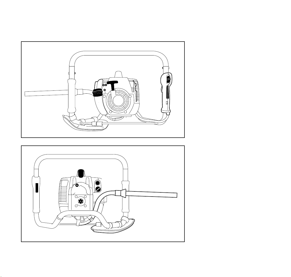
Parts and Controls
8
10
11
English / USA
1= Starter Gri p
2= Carburetor Adjusting Screws
3= Air Filter Cover
4= Fuel Filler Cap
5= Muffler
3
1
2
5
6
(with spark arresting screen)
6= Slide Control
7= Throttle Trigger Interlock
7
4
427BA017 KN
8= Throttle Trigger
9= Spark Plug Boot
10= Screw Plug
9
12
13
14
11= Drilling spindle
12= Fuel Pump
13= Choke Knob
14= Auger Brake Activating Lever
15= Padding
15
427BA011 KN
27BT 120 C
Page 29

English / USA
Specifications
Definitions
1. Starter Grip
The grip of the pull starter, which is
the device to start the engine.
2. Carburetor Adjusting Screws
For tuning the carburetor.
3. Air Filter Cover
Encloses and protects the air filter.
4. Fuel Filler Cap
For closing the fuel tank.
5. Muffler
(with spark arresting screen)
Reduces exhaust noises and
diverts exhaust gases away from
operator.
6. Slide Control
For starting throttle, run and stop.
Keeps the throttle partially open
during starting, switches the
engine’s ignition off to stop the
engine.
7. Throttle Trigger Interlock
Must be depressed before the
throttle trigger can be activated.
8. Throttle Trigger
Controls the speed of the engine.
9. Spark Plug Boot
Connects the spark plug to the
ignition lead.
10. Screw Plug
Seals filler opening for gearbox
grease.
11. Drilling spindle
For attaching the chuck or adapter
to the power drill.
12. Fuel Pump
Provides additional fuel feed for a
cold start.
13. Choke Knob
Operates choke to enrich the
mixture for easier engine starts.
14. Auger Brake Activating Lever
Lever for engaging and disengaging
the auger brake.
15. Padding
Helps cushion thigh against handle
frame.
EPA / CEPA:
The Emission Compliance Period
referred to on the Emissions
Compliance Label indicates the number
of operating hours for which the engine
has been shown to meet Federal
emission requirements.
Category:
A = 300 hours,
B = 125 hours,
C = 50 hours
CARB:
The Emission Compliance Period used
on the CARB Air Index Label indicates
the terms:
Extended = 300 hours,
Intermediate = 125 hours,
Moderate = 50 hours
Engine
STIHL single cylinder two-stroke engine
Displacement: 1.88 cu.in
(30.8 cm
Bore: 1.38 in
(35 mm)
Stroke: 1.26 in
(32 mm)
Engine power
to ISO 8893
Max. engine speed
without auger 12,300 rpm
Idle speed 2,800 rpm
1.8 bhp
(1.3 KW)
3
)
28
BT 120 C
Page 30

English / USA
Ignition System
Type
Electronic magneto ignition with
electronic speed governor
Spark plug (resistor type)
Bosch WSR 6 F, NGK BPMR 7 A or
Champion RCJ 6 Y (not for all markets)
Electrode gap
0.02 in (0.5 mm)
Spark plug thread
M 14 x 1.25; 0.37 in (9.5 mm) long
Fuel System
Carburetor
All position diaphragm carburetor with
integral fuel pump
Air filter
Paper filter element
Fuel tank capacity
1.35 US pt (0.64 l)
Fuel mix
see chapter on "Fuel"
Drilling Gear
Type
Two-stage spur gear drive
Gear ratio
47.5 : 1
Max. spindle speed
190 rpm
Max. torque at drilling spindle
79 Nm
Lubrication
STIHL gear lubricant for brushcutters
Weight
without drilling tool (auger)
18.1 lb (8.2 kg)
Dimensions
Length of machine
approx. 14.2 in (360 mm)
Width of handle frame
approx. 20.5 in (520 mm)
Height without drilling tool (auger)
approx. 13.8 in (350 mm)
Drilling Tools (Augers)
Earth augers
1.6, 2.4, 3.5, 4.7, 5.9, 7.9 in diameter
(40, 60, 90, 120, 150, 200 mm),
27.4 in (695 mm) long
Planting hole auger
10.2 in (260 mm)
Planting auger
6 in (150 mm) diameter,
20.6 in (525 mm) long
Special Accessories
Shaft extension
17.7 in (450 mm) long
Chuck
For drill diameters from
5/64" to 1/2" (2 to 13 mm)
Rewind Starter
Starter rope: 0.11 in (3.0 mm) diameter,
33.5 in (850 mm) long
29BT 120 C
Page 31

English / USA
Maintenance and Repairs
The user of this unit should carry out
only the maintenance operations
described in this manual. Other repair
work may be performed only by an
authorized STIHL dealer.
Warranty claims following repairs can be
accepted only if the repair has been
performed by an authorized STIHL
dealer using original STIHL replacement
parts.
Original STlHL parts can be identified by
the STIHL part number, the
logo and the STlHL parts symbol (.
The symbol may appear alone on small
parts.
STIHl
30
BT 120 C
Page 32

STIHL Incorporated Federal and California Emission Control Warranty Statement
English / USA
Your Warranty Rights
and Obligations
The U.S. Environmental Protection
Agency (EPA), the California Air
Resources Board (CARB) and STIHL
Incorporated are pleased to explain the
Emission Control System Warranty on
your model year 2000 and later
equipment type engine. In California,
new small off-road engines must be
designed, built and equipped to meet the
State's stringent anti-smog standards. In
other states, new 1997 and later model
year small off-road equipment engines
must be designed, built and equipped, at
the time of sale, to meet the U.S. EPA
regulations for small non road engines.
The equipment engine must be free from
defects in materials and workmanship
which cause it to fail to conform with
U.S. EPA standards for the first two
years of engine use from the date of sale
to the ultimate purchaser.
STIHL Incorporated must warrant the
emission control system on your small
off-road engine for the period of time
listed below provided there has been no
abuse, neglect or improper maintenance
of your small off-road equipment engine.
Your emission control system includes
parts such as the carburetor and the
ignition system. Also included may be
hoses, and connectors and other
emission related assemblies.
Where a warrantable condition exists,
STIHL Incorporated will repair your
small off-road equipment engine at no
cost to you, including diagnosis (if the
diagnostic work is performed at an
authorized dealer), parts, and labor.
Manufacturer's Warranty
Coverage:
The small off-road equipment engines
are warranted for two years in California.
In other states, 1997 and later model
year small off-road equipment engines
are also warranted for two years. If any
emission-related part on your engine is
defective, the part will be repaired or
replaced by STIHL Incorporated free of
charge.
Owner's Warranty
Responsibilities:
As the small off-road equipment engine
owner, you are responsible for the performance of the required maintenance
listed in your owner's manual. STIHL
Incorporated recommends that you
retain all receipts covering maintenance
on your small off-road equipment
engine, but STIHL Incorporated cannot
deny warranty solely for the lack of
receipts or for your failure to ensure the
performance of all scheduled
maintenance.
Any replacement part or service that is
equivalent in performance and durability
may be used in non-warranty maintenance or repairs, and shall not reduce the
warranty obligations of the engine
manufacturer.
As the small off-road equipment engine
owner, you should be aware, however,
that STIHL Incorporated may deny you
warranty coverage if your small off-road
equipment engine or a part has failed
due to abuse, neglect, improper
maintenance or unapproved
modifications.
You are responsible for presenting your
small off-road equipment engine to a
STIHL service center as soon as a
problem exists. The warranty repairs will
be completed in a reasonable amount of
time, not to exceed 30 days.
If you have any questions regarding your
warranty rights and responsibilities,
please contact a STIHL customer
service representative at
1-800-467-8445 or you can write to
STIHL Inc., 536 Viking Drive,
P.O . B o x 2 0 1 5 ,
Virginia Beach, VA 23450-2015.
Coverage by STIHL Incorporated
STIHL Incorporated warrants to the
ultimate purchaser and each
subsequent purchaser that your small
off-road equipment engine will be
designed, built and equipped, at the time
of sale, to meet all applicable
regulations. STIHL Incorporated also
warrants to the initial purchaser and
each subsequent purchaser that your
engine is free from defects in materials
and workmanship which cause the
engine to fail to conform with applicable
regulations for a period of two years.
31BT 120 C
Page 33

English / USA
Warranty Period
The warranty periods will begin on the
date the utility equipment engine is
purchased by the initial purchaser and
you have signed and sent back the
warranty card to STIHL. If any emission
related part on your engine is defective,
the part will be replaced by STIHL
Incorporated at no cost to the owner.
Any warranted part which is not
scheduled for replacement as required
maintenance, or which is scheduled only
for regular inspection to the effect of
"repair or replace as necessary" will be
warranted for the warranty period.
Any warranted part which is scheduled
for replacement as required maintenance will be warranted for the period of
time up to the first scheduled replacement point for that part.
Diagnosis
You, as the owner, shall not be charged
for diagnostic labor which leads to the
determination that a warranted part is
defective. However, if you claim
warranty for a component and the
machine is tested as non-defective,
STIHL Incorporated will charge you for
the cost of the emission test.
Mechanical diagnostic work will be
performed at an authorized STIHL
servicing dealer. Emission test may be
performed either at STIHL Incorporated
or at any independent test laboratory.
Warranty Work
STIHL Incorporated shall remedy warranty defects at any authorized STIHL
servicing dealer or warranty station. Any
such work shall be free of charge to the
owner if it is determined that a warranted
part is defective. Any manufacturerapproved or equivalent replacement part
may be used for any warranty
maintenance or repairs on emissionrelated parts and must be provided
without charge to the owner. STIHL
Incorporated is liable for damages to
other engine components caused by the
failure of a warranted part still under
warranty.
The California Air Resources Board's
Emission Warranty Parts List specifically
defines the emission-related warranted
parts. These warranted parts are:
Carburetor
Choke (Cold start enrichment system)
Intake manifold
Air filter
Spark plug
Magneto or electronic ignition system
(ignition module)
Catalytic converter (if applicable)
Fasteners
Where to make a claim for
Warranty Service
Bring the product to any authorized
STIHL servicing dealer and present the
signed warranty card.
Maintenance Requirements
The maintenance instructions in this
manual are based on the application of
the recommended 2-stroke fuel-oil
mixture (see also instruction "Fuel").
Deviations from this recommendation
regarding quality and mixing ratio of fuel
and oil may require shorter maintenance
intervals.
Limitations
This Emission Control Systems Warranty shall not cover any of the following:
: repair or replacement required
because of misuse, neglect or lack
of required maintenance,
: repairs improperly performed or
replacements not conforming to
STIHL Incorporated specifications
that adversely affect performance
and/or durability, and alterations or
modifications not recommended or
approved in writing by STIHL
Incorporated,
and
: replacement of parts and other
services and adjustments
necessary for required maintenance
at and after the first scheduled
replacement point.
32
BT 120 C
Page 34

Contenido
español / EE.UU
Guía para el uso de este manual ... 34
Medidas de seguridad y
técnicas de manejo ........................ 35
Armado de la máquina ................... 42
Ajuste del cable del acelerador* ..... 43
Combustible ................................... 43
Llenado de combustible ................. 44
Freno de barrena ............................ 45
Instalación de la barrena ................ 46
Las tintas contienen aceites vegetales,
el papel es reciclable
Arranque/ parada del motor ............ 46
Instrucciones de manejo ................ 49
Liberación de
una barrena atascada ..................... 50
Limpieza del filtro de aire ............... 50
Manejo del motor ............................ 51
Ajuste del carburador ..................... 51
Revisión de la bujía ........................ 53
Funcionamiento del motor .............. 54
Lubricación de la caja
de engranajes ................................. 55
Sustitución de la cuerda de
arranque y resorte de rebobinado .. 55
Almacenamiento de la máquina ..... 57
Tabla de mantenimiento ................. 58
Impreso en papel sin cloro© ANDREAS STIHL AG & Co. KG, 2003
Piezas y controles .......................... 59
Especificaciones ............................. 61
Mantenimiento y reparación ........... 62
Declaración de garantía de
STIHL Incorporated sobre
sistemas de control de emisiones
según normas Federales y
del Estado de California ................. 63
Permita que solamente las personas
que comprenden la materia tratada en
este manual manejen su motoperforadora.
Para obtener el rendimiento y satisfacción máximos de la motoperforadora
STIHL, es importante leer y comprender
instrucciones de mantenimiento y las
las
precauciones de seguridad
zan en la página 3, antes de usar la
motoperforadora.
Comuníquese con el concesionario o
distribuidor de STIHL si no se entiende
alguna de las instrucciones dadas en el
presente manual.
, que empie-
!Advertencia
Dado que la motoperforadora es una
herramienta de alto par motor accionada
por un motor de gasolina, es necesario
tomar medidas especiales de seguridad
para reducir el riesgo de lesiones personales.
El uso descuidado o inadecuado puede
causar lesiones graves e incluso mortales.
* vea "Guía para el uso de este
manual"
STIHl
0458 427 3021. M1. L3. T. Printed in Germany
33BT 120 C
Page 35

español / EE.UU
Guía para el uso de este
manual
Pictogramas
Todos los pictogramas que se encuentran en la máquina se muestran y explican en este manual.
Las instrucciones de uso y manipulación
vienen acompañadas de ilustraciones.
Símbolos en el texto
Los pasos individuales o procedimientos
descritos en el manual pueden estar
señalados en diferentes maneras:
: Paso o procedimiento sin referencia
directa a una ilustración.
Descripción del paso o procedimiento
que se refiere directamente a la ilustración y contiene los números de referencia que aparecen en la ilustración.
Ejemplo:
Suelte el tornillo (1)
Palanca (2) ...
Además de las instrucciones de uso,
en este manual pueden encontrarse
párrafos a los que usted debe prestar
atención especial. Tales párrafos están
marcados con los símbolos que se
describen a continuación:
Advertencia donde existe el
riesgo de un accidente o lesiones
personales o daños graves a la
propiedad.
Advertencia donde existe el
riesgo de dañar la máquina o
los componentes individuales.
Nota o sugerencia que no es
esencial para el uso de la máquina,
pero puede ayudar al operador a
comprender mejor la situación y
mejorar su manera de manejar la
máquina.
Nota o sugerencia sobre el procedimiento correcto con el fin de evitar
dañar el medio ambiente.
Equipo y características
Este manual de instrucciones
abarca varios modelos con diferentes características. Los componentes que no se encuentran instalados
en todos los modelos y las aplicaciones correspondientes están marcados con un *. Esos componentes
son ofrecidos como accesorios
especiales por el concesionario
STIHL.
Mejoramientos técnicos
La filosofía de STIHL es mejorar continuamente todos su productos. Como
resultado de ello, periódicamente se
introducen cambios de diseño y mejoras. Si las características de funcionamiento o la apariencia de su máquina
difieren de las descritas en este manual,
comuníquese con el concesionario
STIHL para obtener la ayuda que
requiera.
Por lo tanto, no podemos responsabilizarnos por los cambios, modificaciones
o mejoramientos que no hayan sido
cubiertos en este manual.
34
BT 120 C
Page 36

Medidas de seguridad y técnicas de manejo
español / EE.UU
Advertencia
Dado que la motoperforadora es una herramienta
de alto par motor accionada por un motor de
gasolina, es necesario
tomar medidas especiales de seguridad para
reducir el riesgo de lesiones personales.
Es importante que usted
lea, comprenda bien y
respete las siguientes
advertencias y medidas
de seguridad. Lea y com-
prenda el manual del propietario y las instrucciones de seguridad. El uso descuidado o inadecuado de
cualquier motoperforadora puede causar lesiones graves e incluso mortales.
!Advertencia
No preste ni alquile nunca la motoperforadora sin el manual del propietario.
Asegúrese que todas las personas que
utilicen la motoperforadora lean y comprendan la información contenida en
este manual.
Pida a su concesionario STIHL que le
enseñe el manejo de la motoperforadora. Respete todas las disposiciones,
reglamentos y normas de seguridad
locales del caso.
¡Peligro!
Si se taladran o se tocan
alambres eléctricos, se
pueden sufrir sacudidas
eléctricas severas, quemaduras, o la muerte.
Vea "Condiciones de tra-
bajo", más adelante.
!Advertencia
Si se choca contra un objeto duro bajo
tierra con la barrena giratoria, la reducción de velocidad o parada repentina de
la barrena causará fuerzas reactivas. La
transferencia de las fuerzas de rotación
(reactivas) puede hacer que la cabeza
motorizada y sus mangos giren repentinamente en sentido contrahorario, posiblemente causando la pérdida del control, o haciendo que el bastidor de los
mangos golpee al operador o lo lance al
suelo, causando lesiones graves.
!Advertencia
Nunca permita a los niños que usen una
motoperforadora. No se debe permitir la
proximidad de otros, especialmente
niños y animales, donde se esté utilizando la motoperforadora. Nunca deje
la motoperforadora funcionando sin vigilancia.
Vea la sección correspondiente de su
manual del usuario para tener una descripción de los controles y la función de
cada componente de su motoperforadora.
La mayoría de estas medidas de seguridad y avisos se refieren al uso de todas
las motoperforadoras de STIHL. Los distintos modelos pueden contar con piezas y controles diferentes. Vea la sección correspondiente de su manual del
usuario para tener una descripción de
los controles y la función de cada componente de su modelo de motoperforadora.
El uso seguro de una motoperforadora
atañe a
1. el operador
2. la motoperforadora
3. el uso de la motoperforadora.
EL OPERADOR
Condición física
Usted debe estar en buenas condiciones físicas y psíquicas y no encontrarse
bajo la influencia de ninguna sustancia
(drogas, alcohol, etc.) que le pueda restar visibilidad, destreza o juicio. No
maneje la motoperforadora cuando está
fatigado. Esté alerta. Si se cansa
durante el manejo de la motoperforadora, tómese un descanso. El cansancio
puede provocar una pérdida del control.
El uso de cualquier motoperforadora es
fatigoso. Si usted padece de alguna
dolencia que pueda ser agravada por la
fatiga, consulte a su médico antes de
utilizar la motoperforadora.
35BT 120 C
Page 37

español / EE.UU
!Advertencia
El uso prolongado de las motoperforadoras (u otras máquinas) expone al operador a vibraciones que pueden provocar el fenómeno de Raynaud (dedos
blancos) o el síndrome del túnel del carpio. Estas condiciones reducen la capacidad manual de sentir y regular la temperatura, producen entumecimiento y
ardor y pueden provocar trastornos nerviosos y circulatorios, así como necrosis
de los tejidos.
No se conocen todos los factores que
contribuyen a la enfermedad de Raynaud, pero el clima frío, el fumar y las
enfermedades o condiciones físicas que
afectan los vasos sanguíneos y la circulación de la sangre, como asimismo los
niveles altos de vibración y períodos
prolongados de exposición a la vibración son mencionados como factores en
el desarrollo de la enfermedad de Raynaud. Por lo tanto, para reducir el riesgo
de la enfermedad de dedos blancos y
del síndrome del túnel del carpio, sírvase notar lo siguiente:
– Utilice guantes y mantenga las
manos abrigadas.
– Agarre firmemente los mangos en
todo momento, pero no los apriete
con fuerza constante y excesiva.
– Tómese descansos frecuentes.
Todas las precauciones antes mencionadas no le garantizan que va a estar
totalmente protegido contra la enfermedad de Raynaud o el síndrome del túnel
del carpio. Por lo tanto, los operadores
constantes y regulares deben controlar
con frecuencia el estado de sus manos
y dedos. Si aparece alguno de los síntomas arriba mencionados, consulte
inmediatamente al médico.
!Advertencia
El sistema de encendido de la máquina
produce un campo electromagnético de
intensidad muy baja. El mismo puede
interferir con algunos tipos de marcapasos. Para reducir el riesgo de lesiones
graves o mortales, las personas portadoras de marcapasos deben consultar a
sus médicos y al fabricante del marcapasos antes de usar esta máquina.
Vestimenta adecuada
!Advertencia
Para reducir el riesgo de lesiones el
operador debe usar el equipo protector
adecuado.
La ropa debe ser de confección fuerte y ajustada,
pero no tanto que impida
la completa libertad de
movimiento. Evite el uso
de chaquetas sueltas,
pantalones anchos o con vuelta o cualquier cosa que pudiera enredarse en la
herramienta perforadora. Use monos o
pantalones largos para protegerse las
piernas. Sujétese el pelo de modo que
quede sobre los hombros. No vista pantalones cortos. Usar guantes para
manejar la motoperforadora.
Para reducir el riesgo de
sufrir una caída como
resultado de las fuerzas
creadas por la motoperfo-
radora, es sumamente
importante tener buen
apoyo para los pies. Póngase zapatos
gruesos con suela antideslizante. Recomendamos las botas de seguridad con
puntera de acero.
36
BT 120 C
Page 38
español / EE.UU
!Advertencia
Los objetos arrojados o lanzados pueden rebotar y golpear al operador.
Por lo tanto, para reducir
el riesgo de lesionarse los
ojos, nunca maneje la
motoperforadora si no
tiene puestas gafas o
anteojos de seguridad
bien ajustados con una protección adecuada en las partes superior y laterales
que satisfagan la norma ANSI Z 87,1 (o
la norma nacional correspondiente).
!Advertencia
Utilice un casco de segu-
ridad aprobado para pro-
tegerse la cabeza en caso
de existir tal tipo de peli-
gro.
!Advertencia
El ruido de la herramienta
motorizada puede dañar
la motoperforadora.
Siempre use amortigua-
dores del ruido (tapones u
orejeras) para protegerse
los oídos. Los usuarios constantes y
regulares deben someterse con frecuencia a un examen o control auditivo.
LA MOTOPERFORADORA
Para las ilustraciones y definiciones de
los componentes de la motoperforadora, vea "Piezas y controles" y "Definiciones".
Nunca modifique, de ninguna manera, la
motoperforadora. Utilice únicamente los
accesorios de perforación suministrados por STIHL o expresamente autorizados por STIHL para usarse con los
modelos específicos de motoperforadoras de STIHL. Si se usan otras herramientas perforadoras, se puede aumentar el riesgo de lesionarse.
Puede ser posible instalar otros accesorios o adaptadores en la motoperforadora, pero éstos pueden aumentar el
riesgo de lesiones graves o la muerte.
EL USO DE LA MOTOPERFORADORA
Transporte de la motoperforadora
!Advertencia
Antes de apoyar la motoperforadora en
el suelo o de acarrearla, apague el
motor. Es peligroso acarrear la motoperforadora con el motor en marcha.
La aceleración accidental del motor
puede causar la rotación de la herramienta perforadora. Durante el funcionamiento, el silenciador del motor y el
material que lo rodea se calientan a temperaturas sumamente altas. Para evitar
la posibilidad de quemaduras graves, no
coloque una máquina caliente en material seco e inflamable y no toque el silenciador caliente.
Por mano: Lleve la motoperforadora
con la herramienta perforadora orientada hacia atrás – con el silenciador
caliente alejado de su cuerpo.
Transporte en un vehículo: Cuando
transporte la herramienta en un vehículo, sujétela firmemente para impedir
su vuelco, el derrame de combustible y
daños.
Cuando la herramienta no esté en uso,
apáguela y colóquela en el suelo, de
modo que no represente un peligro para
los demás.
!Advertencia
Su motoperforadora
emite gases de escape
tóxicos apenas el motor
de combustión empieza a
funcionar. Estos gases
(por ej., monóxido de carbono) pueden ser incoloros e inodoros.
Para reducir el riesgo de sufrir lesiones
graves o mortales por respirar gases
tóxicos, nunca haga funcionar la motoperforadora puertas adentro o en lugares mal ventilados. Asegúrese de tener
ventilación adecuada cuando trabaje en
zanjas u otros lugares confinados.
37BT 120 C
Page 39

español / EE.UU
La motoperforadora STIHL utiliza una
mezcla de aceite-gasolina como combustible (vea el capítulo "Combustible"
en el manual del propietario).
!Advertencia
La gasolina es un combustible muy inflamable.
Tenga sumo cuidado
cuando manipule gasolina o la mezcla de com-
bustible. No fume cerca
del combustible, ni acerque ningún
fuego o llama al mismo.
Instrucciones para el llenado de combustible
!Advertencia
Cargue de combustible su motoperforadora en lugares al aire libre bien ventilados. Siempre apague el motor y deje
que se enfríe antes de llenar de combustible. Dependiendo del combustible
utilizado, de las condiciones climáticas y
del sistema de ventilación del tanque, es
posible que se forme vapor de gasolina
a presión dentro del tanque de gasolina
de los motores de dos tiempos.
Para reducir el riesgo de quemaduras,
así como otras lesiones corporales ocasionadas por los escapes de vapor de
gasolina y otras emanaciones, quite la
tapa de llenado de combustible de la
motoperforadora cuidadosamente de
modo que la presión que se pueda
haber acumulado en el tanque se disipe
lentamente. Nunca quite la tapa de llenado de combustible mientras el motor
está funcionando.
Elija una superficie despejada para llenar el tanque y aléjese 3 m (10 pies) por
lo menos del lugar en que lo haya llenado antes de arrancar el motor. Limpie
los derrames de combustible antes de
arrancar la motoperforadora y compruebe que no existen fugas.
!Advertencia
Compruebe que no existen fugas de
combustible mientras llena el tanque y
durante el funcionamiento de la
máquina. Si detecta alguna fuga de
combustible o aceite, no arranque el
motor ni lo haga funcionar sin antes
reparar la fuga y limpiar el combustible
derramado. Tenga cuidado de no mancharse la ropa con combustible. Si la
mancha, cámbiesela inmediatamente.
!Advertencia
Las vibraciones de la
máquina pueden aflojar
una tapa de combustible
que ha quedado mal
apretada, o simplemente
soltarla y derramar combustible. Para reducir el riesgo de derrames e incendio, apriete la tapa de llenado de combustible a mano con la
mayor fuerza posible.
Uso de la motoperforadora
La motoperforadora debe ser manejada
por una sola persona.
Para reducir el riesgo de sufrir lesiones
a causa de las fuerzas reactivas, el operador debe sujetar la máquina firmemente y debe tener buen apoyo para los
pies antes de ajustar el acelerador para
arrancar la motoperforadora.
Preparación para el uso de la motoperforadora
Siempre se debe revisar la motoperforadora para comprobar que está en buenas condiciones y que funcionará
correctamente antes de arrancarlo.
Preste atención especial al gatillo de
aceleración, al bloqueo del gatillo, al
interruptor de parada, a la herramienta
perforadora y al freno de barrena.
38
BT 120 C
Page 40

español / EE.UU
!Advertencia
Para reducir el riesgo de lesionarse con
la herramienta perforadora en movimiento o por las fuerzas reactivas, el
gatillo de aceleración debe moverse
libremente y retornar de inmediato a la
posición de ralentí al soltarlo. El mantenimiento periódico es importante en
cuanto a esto. Revise la condición y el
apriete de la herramienta perforadora.
Freno de barrena
Su modelo de motoperforadora tiene un
freno diseñado para reducir la posibilidad de lesiones causadas por las fuerzas reactivas parando la barrena/unidad
motriz al accionar la palanca de freno.
También debe usarse durante el arranque y para liberar una barrena atascada.
Vea el capítulo "Freno de barrena" para
información acerca de la aplicación del
freno.
!Advertencia
No maneje nunca una motoperforadora
que esté dañada, mal ajustada o que no
fue armada debidamente. Se podrían
causar lesiones.
Arranque
Para las instrucciones específicas de
arranque, vea la sección correspondiente en el manual del usuario.
!Advertencia
El operador debe arrancar la motoperforadora únicamente cuando la está sosteniendo firmemente.
Para arrancar la motoperforadora, colóquela sobre suelo firme y limpio u otra
superficie sólida en un lugar abierto.
Mantenga el equilibrio y elija un buen
punto de apoyo para los pies.
!Advertencia
Para reducir el riesgo de la pérdida de
control, verifique que el freno de barrena
esté aplicado antes de arrancar la
máquina. Debido a que la velocidad
alcanzada por el motor durante el arranque es suficiente para que el embrague
impulse la herramienta perforadora, la
herramienta girará a menos que se apli-
427BA001 KN
que el freno de barrena.
!Advertencia
Cuando tire del mango de arranque, no
enrolle la cuerda de arranque alrededor
de la mano. No deje que el mango
vuelva por sí solo a su posición original,
sino guíe lentamente la cuerda con la
mano para que se enrolle correctamente. Si no ejecuta este procedimiento
puede lastimarse la mano o los dedos y
también dañar el mecanismo de arranque.
Ajustes importantes
!Advertencia
Cuando el ralentí está correctamente
regulado, la herramienta perforadora no
debe girar. Para instrucciones cómo
ajustar el ralentí, vea la sección correspondiente en el manual del propietario.
Para reducir el riesgo de lesionarse con
la herramienta perforadora en movimiento, no use una motoperforadora
cuya velocidad de ralentí esté mal ajustada.
39BT 120 C
Page 41

español / EE.UU
Si no puede regular correctamente el
ralentí, pida a su concesionario STIHL
que revise la motoperforadora y haga
los ajustes o reparaciones correspondientes.
Condiciones de trabajo
Si se choca con algún
objeto duro bajo tierra, tal
como piedra o grava, esto
puede hacer que la herramienta perforadora
reduzca su velocidad o se
detenga repentinamente. En una situación semejante, la fuerza rotacional
(reactiva) se transfiere a la unidad
motriz, lo cual puede hacer que la unidad motriz y los mangos giren súbitamente en sentido contrahorario.
!Advertencia
Trabaje con cuidado en suelo rocoso, o
si hay otros objetos sólidos presentes.
Mantenga la presión de alimentación a
un mínimo. Si se percibe o escucha que
la herramienta perforadora ha chocado
con un objeto sólido, suelte el gatillo de
inmediato y quite el objeto antes de continuar perforando. Al perforar en suelo
arcilloso pesado, taladre aproximadamente 1/3 de la profundidad deseada y
extraiga la barrena del agujero. Limpie
la barrena y continúe avanzando lentamente y limpiando el taladro frecuentemente.
!Advertencia
427BA002 KN
Sujete la motoperforadora con firmeza
para controlar los saltos repentinos y las
fuerzas reactivas. Esté preparado para
soltar el gatillo si las fuerzas resultan ser
demasiado grandes. Si no se controlan
las fuerzas reactivas, la rotación de los
mangos puede causar saltos fuertes y la
pérdida de control, y puede hacer el
bastidor de mangos le golpee o le lance
al suelo. Su modelo de motoperforadora
tiene un freno de barrena. Si la barrena
choca contra algo imposible de perforar
y la unidad motriz comienza a girar, la
palanca accionadora choca contra el
muslo del operador y aplica el freno de
barrena para detener la rotación de la
unidad motriz.
!Advertencia
Para reducir la posibilidad de lesiones
graves o la muerte causadas por fuerzas de reacción, nunca utilice la motoperforadora sin un freno de barrena en
buenas condiciones.
Si la barrena se atasca en el agujero
perforado, apague el motor de inmediato y extráigala según se describe en
el capítulo "Retiro de una barrena atascada".
!Advertencia
Maneje y arranque su motoperforadora
exclusivamente al aire libre y en un lugar
bien ventilado. Maneje la barrena solamente cuando tenga buena visibilidad y
a la luz del día. Trabaje con mucho cuidado. Siempre sujete la motoperforadora firmemente con las dos manos.
Envuelva los dedos firmemente en los
mangos, manteniéndolos sujetos entre
los dedos índice y pulgar. Mantenga las
manos en esta posición, para que siempre tenga la motoperforadora bien controlada. Asegúrese que los mangos de
la motoperforadora y el mango de arranque están en buenas condiciones y sin
humedad, resina, aceite o grasa.
PELIGRO
El contacto con cables o
alambres eléctricos
puede causar lesiones
graves o mortales como
resultado de las sacudidas eléctricas. Esta
máquina no está aislada.
40
BT 120 C
Page 42

español / EE.UU
!Advertencia
Para reducir el riesgo de sacudidas
eléctricas y daños a la propiedad, siempre esté atento a la presencia de tubos
y cables subterráneos y de alambres de
tendido eléctrico. Antes de perforar,
obtenga los planos y permisos del caso.
Para mayor información en cuanto a la
ubicación de cables y tuberías, comuníquese con la empresa de servicios
públicos local o con un servicio de localización de líneas y tuberías. De ser
necesario, confirme la ubicación real
usando dispositivos tales como detectores de cables y/o excavando zanjas cuidadosamente. Manténgase alejado de
los cables eléctricos suspendidos al
sacar la herramienta perforadora del
agujero. Si alguna parte de la máquina
choca con un alambre, se causará una
sacudida eléctrica o la muerte.
!Advertencia
Para reducir el riesgo de una caída,
tenga cuidado al transportar o usar la
máquina en condiciones húmedas,
cuando el suelo está húmedo, helado o
cubierto con nieve. Tenga cuidado especial al trabajar sobre bancos de terreno
y pendientes.
Instrucciones de manejo
!Advertencia
Para reducir el riesgo de lesionarse,
nunca toque una herramienta perforadora o árbol de perforación en movimiento con la mano ni con parte alguna
del cuerpo. Este sigue girando por un
rato después que se suelta el gatillo de
aceleración. Siempre apague el motor
antes de poner la máquina en el suelo o
de acarrearla sobre una distancia
grande.
Al sacar la herramienta perforadora del
agujero, levante la máquina en sentido
vertical, de modo que la herramienta
salga directamente hacia afuera, sin
atorarse con las paredes del agujero.
Cubra los agujeros perforados y márquelos de modo claro para evitar que
alguien caiga en un agujero.
Mantenimiento, reparación y
almacenamiento
Los trabajos de mantenimiento,
reemplazo o reparación de los dispositivos y sistemas de control de emisiones de escape pueden ser realizados por cualquier taller o técnico de
motores no diseñados para vehículos. Sin embargo, si usted está reclamando servicio de garantía para
algún componente que no ha sido
reparado o mantenido debidamente,
o cuando se utilizan repuestos no
autorizados, STIHL puede denegar la
garantía.
Utilice solamente piezas de repuesto de
STIHL para el mantenimiento y reparación. La utilización de piezas fabricadas
por otras empresas puede dañar la
motoperforadora o causar lesiones graves. Siga las instrucciones de mantenimiento y reparación dadas en la sección
correspondiente del manual del usuario.
!Advertencia
Siempre apague el motor antes de llevar
a cabo trabajos de mantenimiento o
reparación. No intente hacer ningún trabajo de mantenimiento o reparación que
no esté descrito en su manual del propietario.
Este tipo de trabajo debe realizarse únicamente en el taller de servicio de
STIHL.
41BT 120 C
Page 43

español / EE.UU
Armado de la máquina
!Advertencia
Revise la condición del taladro en intervalos cortos regulares. Si nota algún
cambio en el comportamiento de la
herramienta, revise inmediatamente el
apriete y busque señales de agrietamiento.
!Advertencia
Sustituya las herramientas de perforación dañadas inmediatamente, incluso
si tienen sólo alguna grieta superficial.
Nunca intente reparar las herramientas
de perforación dañadas.
Revise si la tapa de llenado tiene fugas
periódicamente. Use la bujía especificada y asegúrese de que ella y el cable
de encendido están en buen estado.
Mantenga apretadas y limpias tanto la
bujía como la conexión de su alambre.
!Advertencia
Un silenciador desgastado o dañado
constituye un riesgo de incendios y
puede causar la pérdida del oído. Compruebe que el silenciador se encuentra
en buenas condiciones. No use la motoperforadora si el silenciador no funciona
correctamente o si ha sido retirado. No
toque nunca un silenciador caliente,
puede quemarse. Para reducir el riesgo
de incendios, no modifique ni retire parte
alguna del silenciador.
Apriete todas las tuercas, pernos y tornillos, excepto los tornillos de ajuste del
carburador, después de cada uso.
Para todo trabajo de mantenimiento, sírvase consultar la tabla de mantenimiento y la declaración de garantía
que se encuentra al final de este
manual.
Guarde la motoperforadora en un lugar
elevado o con llave lejos del alcance de
los niños y vacíe el tanque de combustible si se va a guardar por más de unos
cuantos días.
3
2
1
3
Instalación de la palanca del freno
de barrena
: Coloque la palanca (1) en la abraza-
dera.
: Coloque la pinza (2) en la palanca.
: Introduzca los tornillos de montaje
(3) y apriételos firmemente.
Ajuste del cable del acelerador*
En manijas de control con control deslizante*:
: Pase al capítulo "Ajuste del cable
del acelerador".
* vea “Guía para el uso de este
manual”
424BA005
42
BT 120 C
Page 44

español / EE.UU
Ajuste del cable del acelerador*
Un cable del acelerador correctamente ajustado es necesario para el
funcionamiento correcto en las posiciones de máxima aceleración,
arranque y ralentí.
Ajuste el cable del acelerador únicamente después de haber armado
la máquina completamente.
: Utilice una herramienta adecuada
para empujar la pieza deslizante
hasta la parte inferior de la ranura
(vea la ilustración).
1
2
: Oprima el bloqueo (1) y oprima el
gatillo de aceleración (2) (aceleración máxima) – esto ajusta el cable
del acelerador correctamente.
002BA163 KN
Combustible
Este motor está certificado para funcionar con una mezcla de 50 a 1 de gasolina sin plomo y aceite STIHL para motores de dos tiempos.
Su motor de dos tiempos requiere una
mezcla de gasolina de calidad y aceite
de calidad para motores de dos tiempos
enfriados por aire.
002BA161 KN
Use gasolina sin plomo regular con un
octanaje mínimo de 89 (R+M/2). Si el
octanaje de la gasolina regular en su
zona es más bajo, use combustible sin
plomo superior.
El combustible de octanaje bajo puede
aumentar la temperatura de funcionamiento del motor. Esto, a su vez,
aumenta el riesgo de que se agarrote el
pistón y se dañe el motor.
La composición química del combustible también es importante. Algunos aditivos de combustible no solamente tienen efectos perjudiciales en los
elastómeros (diafragmas de carburador,
sellos de aceite, tuberías de combustible, etc.), sino también en las piezas
fundidas de magnesio y en los convertidores catalíticos. Esto podría causar
problemas de funcionamiento e incluso
daño del motor. Por esta razón, STIHL
recomienda el uso exclusivo de gasolina
sin plomo de buena calidad.
* vea "Guía para el uso de este
manual"
43BT 120 C
Page 45

español / EE.UU
Llenado de combustible
Use solamente el aceite STIHL para
motores de dos tiempos o un aceite de
marca equivalente para motores de dos
tiempos diseñado para usar exclusivamente con los motores de dos tiempos
enfriados por aire.
Recomendamos el aceite STIHL para
motores de dos tiempos 50:1 pues está
especialmente formulado para usarse
en motores STIHL.
No use aceites para mezclar con designaciones BIA o TCW (para motores de
dos tiempos enfriados por agua) ni otros
aceites para mezclar diseñados para
usar en motores enfriados por agua o
por aire (por ejemplo, para motores
marinos fuera de borda, motonieves,
sierras de cadenas, bicimotos, etc.).
Manipule la gasolina con sumo cuidado.
Evite el contacto directo con la piel y
evite inhalar los vapores de combustible. Cuando se reabastece de combustible, quite primero el envase del vehículo y colóquelo en el suelo antes de
llenarlo. No llene un envase que está en
un vehículo o apoyado sobre el mismo.
Mantenga el envase bien cerrado para
evitar la entrada de humedad a la mezcla.
Según sea necesario, limpie el tanque
de combustible de la máquina y el
envase en que se guarda la mezcla de
combustible.
Duración de la mezcla de combustible
Mezcle una cantidad suficiente de combustible para trabajar unos pocos días,
no lo guarde por más de 3 meses. Guárdelo únicamente en envases aprobados
para combustible. Para el proceso de
mezclado, vierta el aceite en el envase
primero y luego agregue la gasolina.
Cierre el envase y agítelo vigorosamente a mano para asegurar que se
mezclen bien el aceite y la gasolina.
Gasolina
gal
EE.UU.
12.6
2 1/2 6.4
5 12.8
Deseche los envases vacíos usados
para mezclar el aceite únicamente en
vertederos autorizados para ello.
Aceite (STIHL 50:1 ó aceite
de calidad equivalente)
oz fl
EE.UU.
427BA003 KN
Antes de llenar la máquina con combustible, limpie a fondo la tapa de llenado y
la zona alrededor del mismo para evitar
la entrada de tierra al tanque.
Siempre agite la mezcla vigorosamente
en el recipiente antes de llenar la
máquina con combustible.
Para reducir el riesgo de quemaduras, así como otras lesiones corporales ocasionadas por los escapes
de vapor de gasolina y otras emanaciones, quite la tapa de llenado
de combustible cuidadosamente de
modo que la presión que se pueda
haber acumulado en el tanque se
disipe lentamente.
Después de haber llenado la
máquina con combustible, apriete la
tapa del tanque tan firmemente
como sea posible con la mano.
44
BT 120 C
Page 46

Freno de barrena
A
427BA004 KN
427BA005 KN
español / EE.UU
B
427BA006 KN
Cambie el recogedor de combustible
una vez al año.
Antes de guardar la máquina por un
período prolongado, vacíe y limpie el
tanque de combustible. Haga funcionar
el motor hasta que el carburador se
seque.
Aplicación del freno de barrena
: Mueva la palanca a la posición A
para aplicar el freno
– al arrancar el motor
– en ralentí
– para liberar una barrena atascada
Si la barrena se atasca en un obstáculo
en el agujero (tal como raíces o piedras), la unidad motriz girará en sentido
contrahorario y la palanca se empuja
contra el muslo del operador para accionar el freno de barrena.
Soltado del freno de barrena
: Mueva la palanca a la posición B.
45BT 120 C
Page 47

español / EE.UU
Prueba del funcionamiento del
freno de barrena
Antes de empezar a trabajar:
Con el motor funcionando a ralentí, aplique el freno de barrena y abra el acelerador completamente por no más de 3
segundos – la barrena no debe girar.
El freno de barrena está expuesto a desgaste normal.
Verifique que el mismo está funcionando
correctamente antes de empezar a trabajar. Si el freno de barrena no funciona,
pida al concesionario STIHL que lo
repare de inmediato.
Instalación de la barrena
: Apague el motor. Coloque la moto-
perforadora en el suelo con el árbol
de perforación hacia arriba.
: Aplique el freno de barrena.
: Extraiga el pasador de retención (1)
de la espiga de la barrena.
: Empuje la barrena (2) en el árbol de
perforación hasta que se alineen los
agujeros (3).
: Empuje el pasador de retención en
el agujero.
: La pinza de resorte del pasador de
retención debe quedar bien ajustada contra la espiga de la barrena.
Arranque/ parada del motor
A
24BA006
: Respete las medidas de seguridad
– vea el capítulo "Medidas de seguridad".
Aplique el freno de barrena
: Mueva la palanca a la posición A.
427BA005 KN
46
BT 120 C
Page 48

español / EE.UU
3
START
2
1
Arranque
: Empuje la palanca de bloqueo (1)
hacia abajo, oprima el gatillo de
aceleración (2) y sosténgalos en
esa posición.
: Mueva el control deslizante (3) a la
posición de arranque (START) y
manténgalo en esa posición.
: Ahora suelte el gatillo de acelera-
ción, el control deslizante y el bloqueo del gatillo, en el orden indicado. Esta es la posición de
arranque del acelerador.
5
4
392BA027 KN
: Mueva la perilla del estrangulador
(4):
A g si el motor está frío.
A e si el motor está caliente.
(también utilice esta posición si el
motor ha estado en marcha, pero
todavía se encuentra frío)
: Comprima el bulbo de la bomba de
combustible (5) por lo menos cinco
veces.
427BA007 KN
: Coloque la máquina sobre el suelo
de modo que quede bien apoyada.
: Ponga la pie derecha en el bastidor
de mangos y empújelo hacia abajo,
con la mano izquierda en el bastidor
de mangos.
: Con la mano derecha tire lenta-
mente del mango de arranque hasta
que sienta una resistencia definitiva
y en seguida dele un tirón fuerte y
rápido. No tire de la cuerda de
arranque totalmente hasta afuera,
se podría cortar.
: No deje que el mango de arranque
retroceda bruscamente; guíelo lentamente hacia el interior de la caja
de modo que la cuerda se enrolle
debidamente.
: Continúe haciendo girar el motor
hasta que arranque.
427BA008 KN
47BT 120 C
Page 49

español / EE.UU
3
START
2
Cuando el motor empieza a
encenderse:
: Gire la perilla del estrangulador a
e y continúe intentando el arranque del motor.
Tan pronto arranca:
: Oprima el gatillo de aceleración
momentáneamente (2) – el control
deslizante (3) se desplaza a la posición de marcha #, y el motor pasa a
aceleración de ralentí.
.
Ya que el freno de barrena todavía
está aplicado, ha que dejar el motor
regresar a ralentí de inmediato –
de lo contrario se podría dañar el
embrague.
B
392BA028 KN
: Apoye la máquina en la punta de la
barrena.
: Suelte el freno de barrena
moviendo la palanca a la posición
B. La motoperforadora ahora está
lista para usar.
Asegúrese que el carburador esté
correctamente ajustado; la barrena
no debe girar cuando el motor está
funcionando a ralentí.
Para apagar el motor:
: Mueva el control deslizante en el
sentido indicado por c a $
A temperaturas ambiente muy bajas:
Permita que el motor se caliente
Tan pronto arranca:
: Oprima el gatillo de aceleración
momentáneamente para desengranar la posición de arranque del acelerador – el control deslizante se
desplaza a la posición de marcha #,
y el motor regresa a la velocidad de
ralentí.
: Abra el acelerador levemente – cal-
iente el motor por un período breve.
Si el motor no arranca:
427BA006 KN
Si no se movió la perilla del estrangulador a e en un tiempo suficientemente
corto después que el motor empezó a
encenderse, la cámara de combustión
se encuentra "ahogada".
: Gire la perilla de estrangulador a e
: Ponga el control deslizante, el blo-
queo y el gatillo de aceleración en la
posición de arranque.
: Arranque el motor – tire de la
cuerda de arranque rápidamente –
puede ser necesario tirar de ella de
10 a 20 veces
Si el motor todavía no arranca:
: Mueva el control deslizante en el
sentido indicado por c a $
48
BT 120 C
Page 50

español / EE.UU
Instrucciones de manejo
1
: Quite el casquillo de la bujía (1).
: Destornille y seque la bujía.
: Abra el acelerador al máximo.
: Tire de la cuerda de arranque varias
veces para despejar la cámara de
combustión.
: Vuelva a colocar la bujía y conecte
su casquillo, empujándolo firmemente.
: Mueva el control deslizante a la
posición de arranque (START).
: Ponga la perilla del estrangulador
en e – aun si el motor está frío.
: Ahora arranque el motor.
Ajuste del cable del acelerador
: Revise el ajuste del cable del acele-
rador – vea el capítulo "Ajuste del
cable del acelerador".
Si se ha dejado que se agote el combustible y se ha vuelto a llenar el tanque:
427BA009 KN
: Comprima el bulbo de la bomba de
combustible por lo menos cinco
veces.
: Ahora arranque el motor.
Durante el período de rodaje
Una máquina nueva no debe hacerse
funcionar a velocidad alta (aceleración
máxima sin carga) por el lapso que tome
llenar el tanque tres veces. Esto evita la
imposición de cargas innecesariamente
altas durante el período de rodaje. Ya
que todas las piezas móviles deben
asentarse durante el período de rodaje
inicial, durante este tiempo la resistencia
causada por fricción en el motor es más
elevada. El motor desarrolla su potencia
máxima después de haber llenado el
tanque de 5 a 15 veces.
Durante el funcionamiento
Después de un período largo de funcionamiento con el acelerador a fondo,
deje funcionar el motor por un rato en
ralentí de modo que el calor en el motor
sea disipado por la corriente de aire de
enfriamiento. Esto ayuda a evitar que
los componentes montados en el motor
(encendido, carburador) sufran sobrecargas térmicas.
Después de terminar el trabajo
Espere hasta que el motor se enfríe.
Vacíe el tanque de combustible y guarde
la máquina en un lugar seco. Verifique
periódicamente el apriete de todos los
pernos y tuercas accesibles (pero no los
tornillos de ajuste) y vuelva a apretarlos
según se requiera.
49BT 120 C
Page 51

español / EE.UU
Extensión de eje (accesorio especial)
No instale la extensión de eje hasta que
toda la barrena esté en el hoyo.
Al empezar la perforación con la
extensión de eje instalada se
aumenta el riesgo de lesiones personales, ya que la máquina estará
al nivel del pecho y será más difícil
controlarla adecuadamente.
Por la misma razón, hay que quitar
la extensión de eje antes de retirar
la barrena del hoyo.
Liberación de una barrena atascada
A
Si la barrena se atasca en el hoyo - apague el motor inmediatamente.
: Mueva el control deslizante en el
sentido indicado por c a $
: Aplique el freno de barrena
moviendo la palanca a la posición
A.
: Ahora gire la máquina a la izquierda
- en sentido contrahorario - para
destornillar la barrena del suelo.
Limpieza del filtro de aire
1
3
2
427BA005 KN
Si se nota una pérdida considerable de la potencia del motor
: Gire la perilla del estrangulador a
g
: Oprima la lengüeta (1).
: Quite la tapa del filtro (2).
: Quite la tierra suelta del interior de
la tapa y de alrededor del filtro.
: Saque y revise el elemento de filtro
(3) – si está sucio o dañado, instale
un elemento nuevo.
: Coloque el elemento de filtro en la
tapa del filtro.
: Empuje la tapa del filtro en su lugar.
250BA022 KN
50
BT 120 C
Page 52

Manejo del motor Ajuste del carburador
Carburador con tornillo LD
español / EE.UU
Las emisiones de gases de escape son
controladas por el diseño de parámetros
y componentes fundamentales del
motor (por ej. carburación, encendido,
regulación y regulación de la válvula o
lumbrera) sin la adición de ningún
equipo importante.
Información general
El carburador se ajusta en la fábrica al
ajuste estándar.
Este ajuste provee una mezcla óptima
de combustible y aire bajo la mayoría de
las condiciones de funcionamiento.
Ajuste estándar
: Apague el motor.
: Quite la barrena de la máquina.
: Revise el filtro de aire y límpielo o
sustitúyalo de ser necesario.
: Revise que el cable del acelerador
esté debidamente ajustado – reajústelo de ser necesario – vea el
capítulo "Ajuste del cable del acelerador".
+
LD
-
: Gire cuidadosamente el tornillo de
ajuste de ralentí (LD) en sentido
contrahorario (roscas izquierdas)
para enroscarlo en su asiento.
Luego ábralo dos vueltas en sen-
tido horario.
Ajuste de ralentí
: Lleve a cabo el ajuste normal.
: Arranque el motor y caliéntelo.
250BA021 KN
51BT 120 C
Page 53

español / EE.UU
Carburador con tornillos
H, L y LA
El motor se para durante el funcionamiento a ralentí
: Gire el tornillo de ajuste de ralentí
(LD) lentamente en sentido horario
hasta que el motor funcione de
modo suave – la cadena no debe
girar.
El árbol de perforación gira cuando el
motor funciona a ralentí
: Gire el tornillo de ralentí (LD) en
sentido contrahorario hasta que la
herramienta de corte se detenga y
luego gírelo aproximadamente otra
vuelta completa en el mismo sentido a partir de esa posición.
Funcionamiento irregular a ralentí,
aceleración deficiente
: Gire el tornillo de ralentí (LD) len-
tamente en sentido contrahorario
no más de media vuelta.
Información general
El carburador se ajusta en la fábrica al
ajuste estándar.
Este ajuste provee una mezcla óptima
de combustible y aire bajo la mayoría de
las condiciones de funcionamiento.
Con este carburador es posible ajustar
el tornillo de velocidad rápida dentro de
una gama pequeña.
Ajuste estándar
: Apague el motor.
: Quite la barrena de la máquina.
: Revise el filtro de aire y límpielo o
sustitúyalo de ser necesario.
: Revise que el cable del acelerador
esté debidamente ajustado –
reajústelo de ser necesario – vea el
capítulo "Ajuste del cable del acelerador".
L
H
1
LA
: Gire el tornillo de ajuste de veloci-
dad alta (H) en sentido contrahorario hasta su tope
– no más que 3/4 de vuelta.
: Atornille cuidadosamente el tornillo
de velocidad baja (L) en sentido
horario hasta que tope en su
asiento.
Después ábralo una vuelta en sen-
tido contrahorario.
: Arranque el motor y caliéntelo.
: Ajuste la velocidad de ralentí con el
tornillo (LA) hasta que el árbol de
perforación deje de girar.
250BA039 KN
52
BT 120 C
Page 54

español / EE.UU
Revisión de la bujía
Ajuste de ralentí
El motor se para durante el funcionamiento a ralentí
: Efectúe el ajuste estándar del torni-
llo de velocidad baja (L).
: Gire el tornillo de ajuste de ralentí
(LA) en sentido horario hasta que el
motor funcione de modo suave – el
árbol de perforación no debe girar.
El árbol de perforación gira cuando el
motor funciona a ralentí
: Gire el tornillo de ralentí (LA) en
sentido contrahorario hasta que el
árbol de perforación se detenga y
luego gírelo aproximadamente otra
media vuelta a vuelta completa
en el mismo sentido a partir de esa
posición.
Funcionamiento irregular a ralentí,
aceleración deficiente
: Efectúe el ajuste estándar del torni-
llo de velocidad baja (L).
Ajuste de ralentí con mezcla muy
pobre:
: Gire el tornillo de ajuste de veloci-
dad baja (L) en sentido contrahorario hasta que el motor funcione y se
acelere de modo uniforme.
Generalmente es necesario cambiar el
ajuste del tornillo de ralentí (LA) después de cada corrección hecha al tornillo de velocidad baja (L).
Ajuste fino del carburador para funcionamiento a alturas grandes
Puede ser necesario efectuar un ajuste
ligero si el motor no funciona adecuadamente:
: Revise el ajuste estándar.
: Caliente el motor.
: Gire el tornillo de velocidad alta (H)
en sentido horario (mezcla más
pobre):
000BA002 KN
Si la mezcla del combustible es incorrecta (demasiado aceite en la gasolina),
el filtro de aire está sucio, y las condiciones de trabajo no son favorables
(especialmente a aceleraciones intermedias) se afecta la condición de la
bujía.) Estos factores permiten la formación de depósitos en la punta aislante,
los cuales pueden perjudicar el rendimiento.
53BT 120 C
Page 55

español / EE.UU
Funcionamiento del motor
Si el motor pierde potencia, es difícil
arrancarlo o funciona de modo irregular
a ralentí, revise la bujía primero.
: Quite la bujía de la manera descrita
en el capítulo "Arranque / parada
del motor".
: Limpie la bujía si está sucia.
: Revise la distancia entre electrodos
(A) y ajústela según se requiera –
vea las "Especificaciones".
: Utilice únicamente bujías tipo resis-
tencia cuyo margen de rendimiento
sea el aprobado.
Corrija los problemas que hayan causado la contaminación de la bujía:
: Demasiado aceite en la mezcla de
combustible.
: Filtro de aire sucio.
: Condiciones desfavorables de fun-
cionamiento, por ejemplo, funcionando bajo carga parcial.
Instale una bujía nueva después de
aprox. 100 horas de funcionamiento,
o más temprano si los electrodos están
muy gastados.
2
1
Para reducir el riesgo de incendio y
de quemaduras, utilice solamente
las bujías autorizadas por STIHL.
Siempre inserte el casquillo (2) de
la bujía bien apretado en el borne
(1) del tamaño adecuado. (Nota: Si
el borne tiene una tuerca adaptadora SAE desmontable, tiene que
ser instalada.) Una conexión suelta
entre el casquillo de la bujía y el
conector del cable de encendido en
el casquillo puede crear un arco voltaico y encender los vapores del
combustible, provocando un incendio.
Si el funcionamiento del motor es insatisfactorio aunque el filtro de aire está
limpio y el carburador ha sido debidamente ajustado, la causa puede hallarse
en el silenciador.
Solicite al concesionario STIHL que
revise si hay contaminación (coquización) en el silenciador.
002BA071 KN
54
BT 120 C
Page 56

español / EE.UU
Lubricación de la caja de engranajes
1
Revise el nivel de grasa después de
aproximadamente cada 50 horas de funcionamiento.
: Desenrosque el tapón de llenado
(1). Si no se ve grasa en el interior
del tapón de llenado, vuelva a llenar
la caja de engranajes.
2
424BA020
: Aplique el tubo (2) de lubricante
para engranajes STIHL al agujero
de llenado.
: Inyecte 5-10 g (1/4 oz) de grasa en
la caja de engranajes.
No llene en exceso la caja de engranajes.
: Vuelva a colocar el tapón de llenado
y apriételo firmemente.
Sustitución de la cuerda de
arranque y resorte de rebobinado
1
1
1
2
3
4
424BA021
Sustitución de una cuerda de
arranque rota
!El resorte de rebobinado puede
saltar y desenrollarse durante esta
operación. Tenga cuidado para evitar
las lesiones.
: Saque los tornillos (1).
: Retire la caja del ventilador.
: Quite la pinza de resorte (2).
: Quite cuidadosamente el rotor de la
cuerda con la arandela (3) y el trinquete (4).
1
256BA075 KN
256BA032 KN
55BT 120 C
Page 57

español / EE.UU
5
7
6
2
3
256BA034 KN
4
: Saque cuidadosamente la tapa (5)
del mango de arranque.
: Quite el resto de la cuerda del rotor
y del mango.
: Haga un nudo de rizo sencillo en el
extremo de la cuerda de arranque
nueva – vea “Especificaciones” – y
después pase la cuerda por la parte
superior del mango y por el buje de
la cuerda (6).
: Vuelva a instalar la tapa en el
mango.
56
256BA033 KN
: Pase la cuerda a través del rotor y
fíjela con un nudo de rizo simple.
: Cubra la cavidad del cojinete del
rotor de la cuerda con aceite sin
resina - vea "Accesorios especiales".
: Deslice el rotor en el poste del
arrancador. Gírelo hacia uno y otro
lado para engranar la espiral terminal del resorte de rebobinado.
: Vuelva a colocar el trinquete (4).
: Coloque la arandela (3).
: Instale la pinza de resorte (2) en el
poste del arrancador y engánchela
en el vástago del trinquete – la
pinza de resorte debe apuntar en
sentido horario.
256BA032 KN
Tensado del resorte de rebobinado
: Forme un bucle con la cuerda de
arranque sin envolver y utilícelo
para girar el rotor seis revoluciones
completas en sentido contrahorario.
: Sujete y mantenga el rotor inmóvil –
tire de la cuerda y enderécela.
: Suelte el rotor de la cuerda.
256BA035 KN
BT 120 C
Page 58

español / EE.UU
Almacenamiento de la máquina
: Suelte lentamente la cuerda para
que se enrolle en el rotor.
El mango de arranque debe quedar
firmemente en el buje guía de la
cuerda. Si el mango cae hacia un
lado: Dele una vuelta adicional al
rotor de la cuerda para aumentar la
tensión del resorte.
Cuando la cuerda de arranque está
completamente extendida, debe ser
posible girar el rotor 1-1/2 vueltas adicionales.
En caso contrario, el resorte está
sobretensado y podría romperse.
: Quítele una vuelta de la cuerda al
rotor, en tal caso.
: Instale la caja del ventilador.
Sustitución del resorte de rebobinado roto
: Quite el rotor de la cuerda de la
forma descrita en "Sustitución de
una cuerda de arranque rota".
!Los pedazos de resorte en la caja
del ventilador todavía pueden estar bajo
tensión y podrían salir lanzados cuando
los saque de la caja. Para reducir el
riesgo de lesionarse, póngase guantes,
anteojos y protector facial.
: Saque los tornillos (7).
: Retire la caja de resorte y las piezas
del resorte
: Lubrique el resorte de repuesto en
la caja nueva con unas cuantas
gotas de aceite sin resina - vea
"Accesorios especiales".
Coloque el resorte de repuesto con la
caja en su posición – la placa inferior
debe quedar orientada hacia arriba. Si el
resorte se sale de la caja durante la instalación: Colóquelo nuevamente en sentido horario, empezando desde el exterior y avanzando hacia adentro.
: Instale los tornillos.
: Instale el rotor de la cuerda de la
forma descrita en "Sustitución de
una cuerda de arranque rota".
: Tense el resorte de rebobinado.
: Instale la caja del ventilador.
Para intervalos de 3 meses o más:
: Retire la barrena.
: Vacíe y limpie el tanque de combus-
tible en una zona bien ventilada.
: Haga funcionar el motor hasta que
el carburador se seque – esto
ayuda a evitar que los diafragmas
del carburador se peguen.
: Limpie la máquina a fondo - preste
atención especial a las aletas del
cilindro y al filtro de aire.
: Guarde la máquina en un lugar seco
y elevado, o bajo llave – fuera del
alcance de los niños y de otras personas no autorizadas.
57BT 120 C
Page 59

español / EE.UU
Tabla de mantenimiento
Sírvase notar que los intervalos de mantenimiento siguientes son aplicables en
condiciones normales de funcionamiento. Si el tiempo de trabajo por jornada es
más largo que lo normal, o si las condiciones son extremas (zonas polvorientas,
etc.), acorte los intervalos indicados de modo correspondiente.
Inspección visual (condición general,
Máquina completa
Freno de barrena
Mango de control Comprobar funcionamiento
Filtro de aire
Filtro en tanque de combustible
Tanque de combustible Limpiar
Carburador
Bujía Ajustar la distancia entre electrodos
Chispero en silenciador
Todos los tornillos y tuercas accesibles
(salvo los tornillos de ajuste)
Caja de engranajes Relubricar
Arbol de perforación Limpiar
Barrena
fugas)
Limpiar
Comprobar funcionamiento
Solicitar al concesionario STIHL su
mantenimiento
Limpiar
Reemplazar
Revisar
Reemplazar
Comprobar el ajuste de ralentí – el
árbol de perforación no debe girar
Ajustar el ralentí
Solicitar al concesionario STIHL su
verificación
Volver a apretar
Inspeccionar
Reemplazar
antes de comenzar el trabajo
después de terminar el trabajo
o diariamente
después de cada parada
para cargar combustible
semanalmente
Xx
X
XX
XX
X
X
X
mensualmente
anualmente
si hay problema
si tiene daños
según se requiera
X
X
X
X
XX
X
X
X
X
X
X
58
BT 120 C
Page 60

Piezas y controles
4
8
10
11
español / EE.UU
1= Empuñadura de arranque
2= Tornillos de ajuste del carburador
3= Tapa del filtro de aire
4= Tapa de llenado de combustible
5= Silenciador (con chispero)
3
1
2
5
6
6= Control deslizante
7= Bloqueo del gatillo de aceleración
7
4
27BA017 KN
8= Gatillo de aceleración
9= Casquillo de la bujía
10= Ta pó n
9
12
13
14
11= Arbol de perforación
12= Bomba de combustible
13= Perilla de estrangulador
14= Palanca del freno de barrena
15= Almohadilla
15
427BA011 KN
59BT 120 C
Page 61

español / EE.UU
Definiciones
1. Empuñadura de arranque
La empuñadura de la cuerda de
arranque, el dispositivo usado para
arrancar el motor.
2. Tornillos de ajuste del carbura-
dor
Para afinar el carburador.
3. Tapa del filtro de aire
Encierra y protege el filtro de aire.
4. Tapa de llenado de combustible
Para tapar el tanque de combustible.
5. Silenciador
(con chispero)
Reduce los ruidos del tubo de
escape y desvía los gases de
escape lejos del operador.
6. Control deslizante
Para arrancar, hacer funcionar y
parar el motor. Mantiene el acelerador parcialmente abierto durante el
arranque, apaga el encendido del
motor y detiene su marcha.
7. Bloqueo del gatillo de acelera-
ción
Hay que oprimirlo para poder activar el gatillo de aceleración.
8. Gatillo de aceleración
Regula la velocidad del motor.
9. Casquillo de la bujía
Conecta la bujía al alambre de
encendido.
10. Tapón
Sella la abertura de llenado de
grasa de la caja de engranajes.
11. Arbol de perforación
Para fijar el portabrocas o adaptador al taladro motorizado
12. Bomba de combustible
Suministra alimentación adicional
de combustible para el arranque en
frío.
13. Perilla de estrangulador
Acciona el estrangulador para enriquecer la mezcla y facilitar el arranque del motor.
14. Palanca del freno de barrena
Palanca para accionar y soltar el
freno de barrena.
15. Almohadilla
Ayuda a proteger el muslo contra el
impacto del bastidor de mangos.
60
BT 120 C
Page 62

Especificaciones
español / EE.UU
EPA / CEPA:
El período de cumplimiento de emisiones indicado en la etiqueta de cumplimiento de emisiones es la cantidad de
horas de funcionamiento para la cual la
máquina ha demostrado la conformidad
con los requerimientos de emisiones del
Gobierno federal de los EE.UU.
Categoría:
A = 300 horas,
B = 125 horas,
C = 50 horas
CARB:
El período de cumplimiento de emisiones empleado en la etiqueta del índice
de aire CARB tiene las siguientes definiciones:
Extended (extendido) = 300 horas
Intermediate (intermedio) = 125 horas
Moderate (moderado) = 50 horas
Motor
Motor STIHL de un cilindro, dos tiempos
Cilindrada: 30,8 cm3 (1,88 pulg3)
Potencia del
motor según
ISO 8893
Velocidad
máx. del
motor sin
barrena
Velocidad
de ralentí
1,3 kW
(1,8 hp)
12 300 rpm
2800 rpm
Sistema de encendido
Tipo
Electrónico con magneto y gobernador
electrónico de velocidad
Bujía (tipo resistor)
Bosch WSR 6 F, NGK BPMR 7 A o
Champion RCJ 6 Y (no en todos los
mercados)
Distancia entre electrodos
0,5 mm (0,02 pulg)
Roscas de la bujía
M 14 x 1,25; 9,5 mm (0.37 pulg) de largo
Sistema de combustible
Carburador
Carburador de diafragma de todas posiciones con bomba de combustible integral
Filtro de aire
Elemento de papel
Capacidad del tanque
de combustible
0,64 l (1,35 pt EE.UU)
Mezcla de combustible
vea el capítulo "Combustible"
Diámetro 35 mm (1,38 pulg)
Carrera: 32 mm (1,26 pulg)
61BT 120 C
Page 63

español / EE.UU
Mantenimiento y reparación
Mecanismo de perforación
Tipo
Mando de engranajes de dientes rectos
de 2 etapas
Relación de reducción
47,5 : 1
Velocidad máxima del árbol
190 rpm
Par motor máximo en el
árbol de perforación
79 Nm
Lubricación
Lubricante para engranajes STIHL para
cortadoras de matorrales
Peso
sin herramienta de perforación
(barrena)
8,2 kg (18,1 lb)
Dimensiones
Largo de la máquina
aprox. 360 mm (14,2 pulg)
Ancho del bastidor de mangos
aprox. 520 mm (20,5 pulg)
Altura sin la herramienta de perforación (barrena)
aprox. 350 mm (13,8 pulg)
Herramientas de perforación
(Barrenas)
Barrenas
40, 60, 90, 120, 150, 200 mm
(1,6; 2,4; 3,5; 4,7; 5,9; 7,9 pulg) de diámetro, 695 mm (27,4 pulg) de largo
Barrena para siembra
260 mm (10,2 pulg)
Sinfín plantador
150 mm (6 pulg) de diámetro,
525 mm (20,6 pulg) de largo
Accesorios especiales
Extensión de eje
450 mm (17,7 pulg) de largo
Portabrocas
Para brocas de 2 a 13 mm
(5/64 a 1/2 pulg) de diámetro
El usuario de esta máquina deberá realizar solamente los trabajos de mantenimiento descritos en este manual. Otros
trabajos de reparación debe hacerlos
solamente un técnico de servicio autorizado por STIHL.
Los reclamos de garantía serán aceptados únicamente si la reparación fue
hecha por un concesionario de servicio
autorizado por STIHL usando repuestos
originales de STIHL.
Los repuestos originales de STIHL se
pueden identificar por el número de
pieza de STIHL, el logotipo
y el símbolo de piezas de STIHL(
En las piezas pequeñas, el símbolo
puede aparecer solo.
STIHl
Arrancador de cuerda
Cuerda de arranque: 3,0 mm (0,11 pulg)
de diámetro, 850 mm (33,5 pulg) de
largo
62
BT 120 C
Page 64

Declaración de garantía de STIHL Incorporated sobre sistemas de control de emisiones según normas Federales y del
Estado de California
español / EE.UU
Sus derechos y obligaciones de
garantía
La Agencia de Protección del Medio
Ambiente (EPA) de los EE.UU., el Consejo de Recursos del Aire del Estado de
California (CARB) y STIHL Incorporated
se complacen en explicarle la garantía
del sistema de control de emisiones instalado en el motor de su equipo de
modelos año 2000 y siguientes. En California, los nuevos motores pequeños
para uso fuera de carretera deben estar
diseñados, construidos y equipados de
conformidad con las rigurosas normas
de contaminación del aire del estado. En
otros estados, los modelos 1997 y posteriores de tales motores deben estar
diseñados, construidos y equipados, al
tiempo de la venta, de conformidad con
los reglamentos correspondientes de la
EPA. El motor debe carecer de defectos
en el material y la fabricación que puedan causar el incumplimiento de las normas de la EPA durante los primeros dos
años de uso del motor a partir de la
fecha de compra por el último comprador. STIHL Incorporated debe garantizar
el sistema de control de emisiones en el
motor pequeño para uso fuera de carretera por el intervalo mencionado más
arriba, siempre que dicho motor no haya
estado sujeto a maltrato, negligencia o
cuidado inapropiado.
El sistema de control de emisiones de
su máquina incluye piezas tales como el
carburador y el sistema de encendido.
Además puede incluir mangueras,
conectores y otros conjuntos relativos a
emisiones.
Si existe una condición amparada bajo
garantía, STIHL Incorporated reparará
el motor sin costo alguno, incluido el
diagnóstico (si el trabajo de diagnóstico
fue realizado por un concesionario autorizado), las piezas y la mano de obra.
Cobertura de garantía del fabricante:
Los motores pequeños para equipos de
uso fuera de carretera están garantizados por dos años en el Estado de California. En otros estados, los modeles de
1997 y posteriores de tales motores
también están garantizados por dos
años. En el caso de encontrarse defectos en cualquiera de las piezas del
motor relacionadas con el sistema de
control de emisiones, la pieza será reparada o sustituida por STIHL Incorporated sin costo alguno.
Responsabilidades del usuario
relativas a la garantía:
Como propietario de tal motor, usted
tiene la responsabilidad de realizar el
mantenimiento requerido descrito en su
manual del usuario. STIHL Incorporated
le recomienda guardar todos los recibos
comprobantes de los trabajos de mantenimiento hechos a su motor, pero STIHL
Incorporated no puede negar garantía
basado en el solo hecho de faltar los
recibos o del incumplimiento del propietario de realizar todos los trabajos de
mantenimiento programados.
El uso de cualquier pieza de repuesto o
servicio cuyo comportamiento y durabilidad sean equivalentes está permitido en
trabajos de mantenimiento o reparación
no contemplados en la garantía, y no
reducirá las obligaciones de la garantía
del fabricante del motor.
Sin embargo, como propietario del
motor pequeño para equipo de uso
fuera de carretera usted debe ser consciente de que STIHL Incorporated
puede negarle cobertura de garantía si
dicho motor o una pieza del mismo ha
fallado debido a maltrato, descuido,
mantenimiento inadecuado o modificaciones no autorizadas.
Usted es responsable de llevar el motor
a un centro de servicio STIHL tan pronto
surja el problema. Las reparaciones
bajo garantía serán realizadas en un
tiempo razonable, sin exceder de 30
días. Ante cualquier duda respecto a
sus derechos y responsabilidades
según lo estipulado en esta garantía,
comuníquese con el representante de
STIHL al 1-800-467-8445 ó escriba a
STIHL Inc., 536 Viking Drive, P.O. Box
2015, Virginia Beach, VA 23450-2015.
Cobertura por STIHL Incorporated
STIHL Incorporated garantiza al último
comprador y a cada comprador subsiguiente que el motor pequeño para
equipo de uso fuera de carretera está
diseñado, construido y equipado, al
tiempo de la venta, de conformidad con
todos los reglamentos aplicables. Además, STIHL Incorporated garantiza al
comprador inicial y a cada comprador
subsiguiente que el motor está libre de
defectos en el material y fabricación que
puedan causar el incumplimiento de los
reglamentos aplicables durante un
período de dos años.
63BT 120 C
Page 65

español / EE.UU
Período de garantía
El período de garantía comienza en la
fecha en que el motor del equipo utilitario es entregado a usted y usted firma y
remite la tarjeta de garantía a STIHL.
Si cualquier pieza relacionada con el
sistema de control de emisiones está
defectuosa, la pieza será sustituida por
STIHL Incorporated sin costo alguno
para el propietario. Cualquier pieza
garantizada cuyo reemplazo no está
programado como mantenimiento
requerido, o que debe recibir únicamente inspección regular en el sentido
de "reparar o sustituir según sea necesario", estará garantizada por el período
de garantía. Cualquier pieza cuyo reemplazo está programado como mantenimiento requerido estará garantizada por
el intervalo hasta el primer punto de
reemplazo programado para esa pieza.
Diagnóstico
Como propietario, a usted no se le debe
cobrar la mano de obra por los diagnósticos que determinen que una pieza
garantizada está defectuosa. No obstante, si usted reclama garantía para un
componente y se comprueba que la
máquina no está defectuosa, STIHL
Incorporated le cobrará el costo de la
prueba del sistema de control de emisiones.
El trabajo de diagnóstico mecánico se
realiza en un centro de servicio autorizado por STIHL. La prueba del sistema
de control de emisiones se realiza ya
sea en la fábrica de STIHL Incorporated
o en un laboratorio de ensayos independiente.
Trabajo bajo garantía
STIHL Incorporated reparará los defectos amparados por la garantía en cualquier estación de garantía o centro de
servicio autorizado por STIHL. Todo trabajo de este tipo se hará gratis para el
propietario siempre que se determine
que la pieza cubierta por la garantía está
defectuosa. Se puede usar cualquier
pieza de repuesto aprobada por el fabricante o equivalente en las piezas relacionadas con el sistema de control de
emisiones, y debe ser suministrada gratis al propietario. STIHL Incorporated es
responsable por daños a otros componentes del motor causados por la falla
de una pieza garantizada que todavía
está bajo garantía.
La lista de piezas del sistema de control
de emisiones garantizadas del Consejo
de Recursos del Aire del Estado de California define específicamente las piezas
garantizadas que están relacionadas
con las emisiones. Estas piezas garantizadas son:
Carburador
Estrangulador (sistema de refuerzo para
arranque en frío)
Múltiple de admisión
Filtro de aire
Bujía
Magneto o sistema de encendido electrónico (módulo de encendido)
Convertidor catalítico (si lo tiene)
Sujetadores/pernos
Dónde presentar el reclamo para
servicio bajo garantía
Lleve el producto a cualquier centro de
servicio autorizado por STIHL y presente la tarjeta de garantía firmada.
Requerimientos de mantenimiento
Las instrucciones presentadas en este
manual se basan en la aplicación de la
mezcla recomendada para motores de
2 tiempos (vea también la instrucción
"Combustible"). Las discrepancias de
estas recomendaciones con respecto a
la calidad y la proporción de la mezcla
de combustible y aceite pueden exigir
intervalos de mantenimiento más cortos.
Limitaciones
Esta garantía de los sistemas de control
de emisiones no cubrirá ninguno de los
puntos siguientes:
: reparación o sustitución requerida
debido a maltrato, negligencia o
falta del mantenimiento requerido,
: reparaciones mal hechas o sustitu-
ciones contrarias a las especificaciones de STIHL Incorporated que
afecten desfavorablemente el funcionamiento y/o la durabilidad, y las
alteraciones o modificaciones no
recomendadas o aprobadas por
escrito por STIHL Incorporated,
y
: la sustitución de piezas y otros ser-
vicios y ajustes necesarios para el
mantenimiento requerido en y después del primer punto de reemplazo
programado.
64
BT 120 C
Page 66

! WARNING!
! WARNING!
! ADVERTENCIA!
The engine exhaust from this product
The engine exhaust from this product
contains chemicals known to the State
contains chemicals known to the State
of California to cause cancer, birth
of California to cause cancer, birth
defects or other reproductive harm.
defects or other reproductive harm.
El gas de escape del motor de esta máquina
contiene productos químicos que en el estado de
California son considerados como causantes de
cáncer, defectos de nacimiento u otros efectos
nocivos para los órganos de la reproducción.
0458 427 3021
englisch / English USA / spanisch / español EE.UU / CARB / EPA
 Loading...