

Stihl 088 Owner's Manual

CONTENTS
1. Introduction 2
2. Specifications 3
2.1 Engine 3
2.2 Fuel System 3
2.3 Ignition System 4
2.4 Cutting Attachment 4
2.5 Special Accessories 5
2.5.1 For User 5
2.5.2 For Service 5
2.6 Tightening Torques 5
3. Clutch, Chain Drive,
Chain Brake and
Chain Tensioner 7
3.1 Clutch Drum/
Chain Sprocket 7
3.2 Clutch 8
3.3 Chain Brake 9
3.3.1 Disassembly 9
3.3.2 Assembly 10
3.3.3 Checking Function 12
3.3.4 Brake Spring
Anchor Pin 13
3.3.5 Hand Guard Pivot Pin 13
3.4 Chain Tensioner 14
4. Engine 15
5. Ignition System 33
5.1 Ignition Module 33
5.1.1 Ignition Timing 34
5.1.2 Removing and
Installing 34
5.2 Spark Plug Boot/
Ignition Lead 35
5.3 Flywheel 36
5.4 Ground Wire/
Short Circuit Wire 37
5.5 Contact Spring 37
6. Rewind Starter 38
6.1. General 38
6.2 Rewind Spring 38
6.2.1 Replacing 38
6.2.2 Tensioning 39
7. AV Handle System 40
8. Master Control/
Handle System 41
8.1 Switch Shaft 41
8.2 Throttle Trigger/
Interlock Lever 42
10. Fuel System 47
10.1 Air Filter 47
10.2 Carburetor 48
10.2.1 Removing and
Installing 48
10.2.2 Leakage Test 49
10.2.3 Adjustment 50
10.3 Tank Vent 51
10.4 Pickup Body 51
10.5 Fuel Hoses 52
10.6 Tank Housing 53
11. Special Servicing
Tools and Aids 56
11.1 Special Servicing Tools 56
11.2 Servicing Aids 58
4.1 Exhaust Muffler/
Spark Arresting Screen 15
4.2 Leakage Test 16
4.2.1 Preparations 16
4.2.2 Pressure Test 17
4.2.3 Vacuum Test 18
4.3 Oil Seals 19
4.4 Exposing the Cylinder 20
4.5 Cylinder and Piston 20
4.5.1 Removal 20
4.5.2 Installation 21
4.6 Piston Rings 24
4.7 Crankcase 24
4.7.1 Removing the
Crankshaft 24
4.7.2 Installing the
Crankshaft 28
4.8 Decompression Valve 32
9. Chain Lubrication 43
9.1 Pickup Body/
Suction Hose 43
9.2 Valve 44
9.3 Spur Gear 44
9.4 Oil Pump 45
9.4.1 Removing and
Installing 45
9.4.2 Servicing 45
STIHl
© 1996. Andreas Stihl. Waiblingen
STIHL 088 1
1. INTRODUCTION
This service manual contains detailed
descriptions of all the repair and
servicing procedures specific to this
series of chainsaws. There are
separate handbooks for servicing
procedures on standardized parts and
assemblies that are installed in several
STIHL power tool models. Reference
is made to these handbooks in the
appropriate chapters of this manual.
You should make use of the illustrated
parts lists while carrying out repair
work. They show the installed positions
of the individual components and
assemblies.
Always use the latest edition of the
parts list to determine the part numbers
of any replacement parts required.
Microfilmed parts list are always more
up to date than printed lists.
A fault on the machine may have
several causes. Consult the
troubleshooting charts for all
assemblies in the "Standard Repairs,
Troubleshooting" handbook.
Refer to the "Technical Information"
bulletins for engineering changes which
have been introduced since publication
of this service manual. Technical
information bulletins also supplement
the parts list until a revised edition is
issued.
The special servicing tools mentioned
in the descriptions are listed in the last
chapter of this manual. Use the part
numbers to identify the tools in the
"STIHL Special Tools" manual. The
manual lists all special servicing tools
currently available from STIHL.
Symbols are included in the text and
pictures for greater clarity. The
meanings are as follows:
In the descriptions:
• = Action to be taken as shown in
the illustration (above the text)
- = Action to be taken that
is not shown in the illustration
(above the text)
In the illustrations:
P = Pointer
= Direction of movement
Service manuals and all technical
information bulletins describing
engineering changes are intended
exclusively for the use of STIHL
servicing dealers. They must not be
passed to third parties.
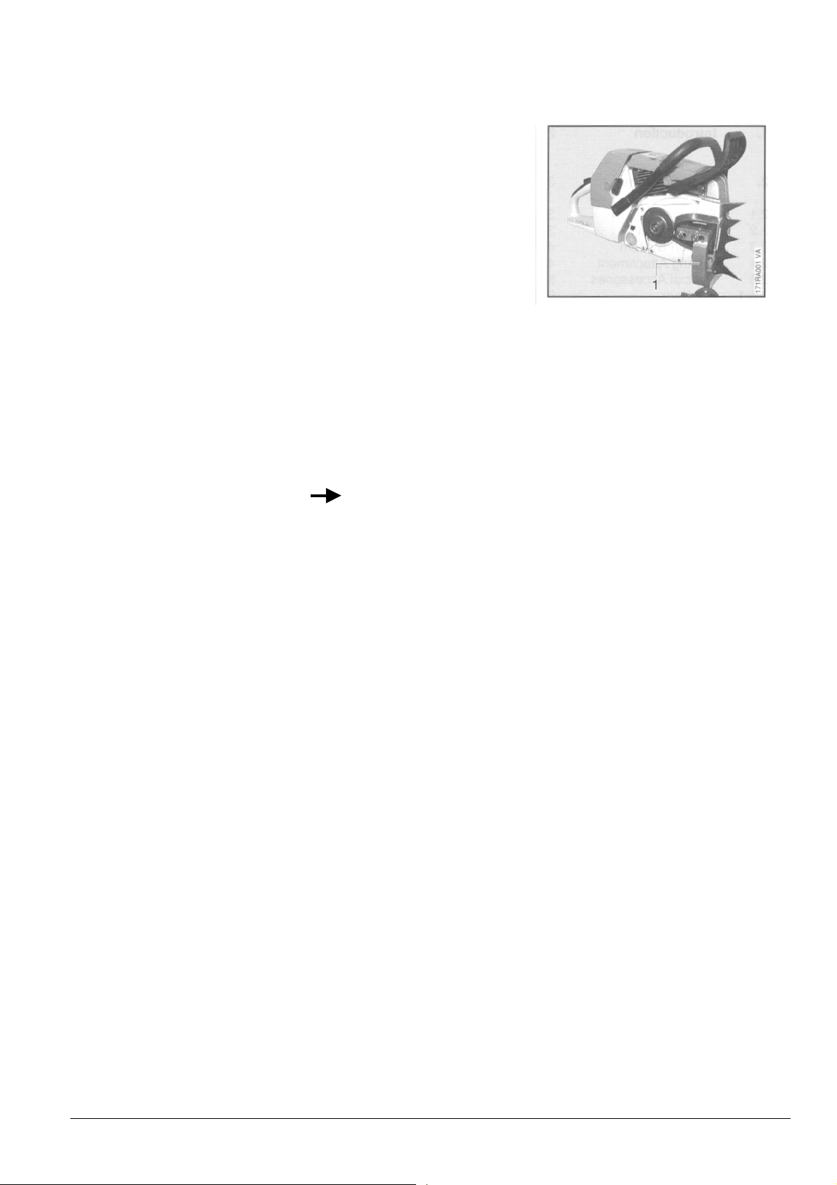
Servicing and repairs are made
considerably easier if the powerhead
is mounted to the assembly stand
(1) 5910 890 3100.
This enables the powerhead to be
swivelled to the best position for the
ongoing repair and leaves both hands
free.
Always use original STIHL
replacement parts. They can be
identified by the STIHL part number,
STIHl
the
and the STIHL parts symbol (
The symbol may appear alone on small
parts.
logo
STIHL 088 2

2. SPECIFICATIONS
3
2.1 Engine
STIHL single cylinder two-stroke engine with special
impregnated cylinder bore
Displacement:
Bore:
Stroke:
Engine power:
Max. torque:
121.6 cm
60 mm (2.35 in)
43 mm (1.69 in)
6.3 kW (8.6 bhp)
8.0 Nm (5.9 Ib.ft)
at 6,000 rpm
Max. engine speed:
Main bearings:
Big-end bearing:
Small-end bearing:
Piston pin diameter:
Connecting rod length:
Rewind starter:
Pawls:
Reserve pull on rope rotor:
Starter rope:
12,000 rpm
Two deep-groove ball bearings
Needle cage
Needle cage
13 mm (0.51 in)
75 mm (2.95 in)
ElastoStart
Two-pawl system
min. 2 turns
4.5 mm (0.18 in) dia.,
1000 mm (39.4 in) long
Clutch:
Diameter:
Clutch engages at:
Centrifugal clutch without linings
87 mm (3.4 in)
3.200 rpm
Crankcase leakage
test at gauge pressure:
under vacuum:
0.6 bar (8.7 psi)
0.4 bar (5.8 psi)
(7.42 cu.in)
2.2 Fuel System
Carburetor:
Standard setting
High speed screw H:
Low speed screw L:
Carburetor leakage test
at gauge pressure:
Function of tank vent
at gauge pressure:
under vacuum:
Fuel tank capacity:
Octane number:
Fuel mixture:
Mix ratio:
Air filter:
Diaphragm carburetor
Open approx. 1 turn
Open approx. 1 turn
0.8 bar (11.6 psi)
≤ 0.5 bar (7.25 psi)
≤ 0.1 bar (1.45 psi)
1.3 I (2.75 US pt)
min. 90 RON (US/CAN: pump
octane min. 87 unleaded)
Regular brand-name gasoline
and two-stroke engine oil
50:1 with STIHL 50:1 two-stroke
engine oil
25:1 with other brand-name
two-stroke, air cooled engine oils
Standard filter (green) with wire
mesh element for normal operating
conditions and winter operation
or
HD filter (special accessory)
STIHL 088 3

2.3. Ignition System
Type:
Air gap:
Ignition timing:
Spark plug (suppressed):
Electrode gap:
Spark plug thread:
Length of thread:
Heat range:
Electronic magneto ignition
(breakerless) with integral
trigger unit
0.2 - 0.3 mm (0.008-0.012 in)
2.3 - 3.3 mm (0.091-0.130 in)
B.TD.C. at 8,000 rpm
Bosch WSR 6F or
NGK BPMR 7 A
0.5 mm (0.02 in)
M14x1.25
9.5 mm (0.37 in)
200
2.4 Cutting Attachment
Guide bars
Bar tail: Bar lengths:
Oilomatic chain:
Chain sprockets:
Chain speed:
Chain lubrication:
Oil delivery rate:
Oil tank capacity:
STIHL Rollomatic
with nose sprocket
STIHL Duromatic with
Stellite-tipped nose.
Both types with corrosionresistant finish and induction
hardened rails.
3002
Rollomatic: 53, 63, 75, 90
and 105 cm
(21, 25, 30, 35 and 41 in)
Duromatic: 53, 63, 75, 90, 105,
120 and 150 cm
(21, 25, 30, 35, 47, 59 in)
10.26 mm (0.404")
Rapid-Micro and Rapid-Super
(standard equipment)
9.32 mm (3/8")
Rapid-Micro and Rapid-Super
as well as 12.7 mm (1/2")
Rapid-Standard available
as options
7-tooth 0.404" rim or
spur sprocket
(standard equipment)
8-tooth 3/8" rim and
spur sprockets
23.9 m/s (78.4 ft/sec) at 8,500 rpm
(with 7-tooth 0.404" sprocket)
Fully automatic speed-controlled
reciprocating oil pump,
no oil feed at idle speed.
Additional manual oil flow
control (with E-matic mark)
Adjustable 17 - 38 cm³/min
(0.6 - 1.3 fl.oz/min) at 10,000 rpm
0.70 1 (1.48 US pt)
STIHL 088 4

2.5 Special Accessories
2.5.1 For User
2.5.2 For Service
2.6 Tightening Torques
Plastoform screws are used for polymer components. These screws form a permanent thread when they are installed
for the first time. They can be removed and installed as often as necessary without detrimentally affecting the strength
of the screwed assembly, providing the specified tightening torque is observed. For this reason it is essential to use a
torque wrench.
Fastener
Thread size
STIHL repair kit 084/088
HD air filter kit
Intake air preheating kit
Carburetor parts kit
Gasket kit 088
For component
1124 900 5001
0000 120 1650
1124 007 1005
1124 007 1061
1124 007 1051
Torque
Nm Ibf.ft
Remarks
Spline screw
Spline screw
Spline screw
Spline screw
Spline screw
Spline screw
Spline screw
Spline screw
Spline screw
Spline screw
Spline screw
Spline screw
Spline screw
Collar nut
Collar nut
Spline screw
Spline screw
Spline screw
IS-B3.9x13
IS-B3.9x19
IS-B3.9x19
IS-M4x8
IS-M4x8
IS-M4x12
IS-M4x12
IS-M4x12
IS-M4x12
IS-M4x12
IS-M4x12
IS-M4x12
IS-M4x12
M5
M5
IS-M5x12
IS-M5x16
IS-M5x20
Cover plate/sprocket cover
Tank housing/handle molding
Switch shaft pivot/tank housing
Cover plate/chain tensioner
Inner side plate/crankcase
Segment/fan housing
Oil pump/crankcase front,
bottom, rear
Chain brake cover/crankcase
Oil pump/crankcase
front top
Brake band/crankcase
Oil pump cover/crankcase
Exhaust cover/muffler
Spur gear cover/crankcase
Shroud/cylinder
Tank housing/carburetor/flange
Top left annular buffer plate/
crankcase
Support/muffler
Shroud/crankcase
1.5 1.1
1.0 0.75
1.0 0.75
3.0 2.2
3.0 2.2
2.5 1.8
3.5 2.6
3.0 2.2
3.5 2.6
3.0 2.2
3.0 2.2
4.0 3.0
3.0 2.2
7.0 5.2
5.0 3.7
9.0 6.6
10.0 7.5
7.0 5.2
1)
2)
2)
STIHL 088 5

Fastener
Thread
size
For component
Torque
Nm Ibf.ft
Remarks
Spline screw
Screw assembly
Spline screw
Spline screw
Nut
Spline screw
Spline screw
Spline screw
Spline screw
Spline screw
Nut
Plastoform screw
Plastoform screw
Plastoform screw
Nut
IS-M5x20
IS-M5x35
IS-M5x25
IS-M5x25
M6
IS-M6x18
IS-M6x18
IS-M5x16
IS-M6x40
IS-M6x30
M10x1
M10x1
M 10x27
M14x1
M 14x1.25
IS-P6x19
IS-P6x21.5
IS-P6x32.5 1.8
M5
Fan housing/crankcase
Hand guard/fan housing/
crankcase
Ignition module/crankcase
Crankcase
Spiked bumper/chain sprocket cover
Spiked bumper/crankcase, bottom
Spiked bumper/crankcase, top
Support/crankcase
Annular buffer, top left/tank housing
Cylinder/crankcase
Flywheel/crankshaft
Decompression valve
Bar mounting stud
Clutch carrier/crankshaft
Spark plug
Annular buffer, bottom/tank housing
Front handle, bottom/tank housing
Front handle, right, stiffener/
tank housing
Chain catcher/spiked bumper
7.0 5.2
7.0 5.2
9.0 6.6
11.5 8.5
7.5 5.5
7.5 5.5
7.5 5.5
10.0 7.5
7.0 5.2
15.0 3.7
45.0 33.0
14.0 10.3
30.0 22.0
80.0 59.0
25.0 18.5
5.5 4.0
8.0 5.9
8.0 5.9
6.0 4.4
2 )
2 )
2)
2)
2)
3)
3 )
4 )
Use the following procedure when refitting a Plastoform screw in an existing thread:
- Place the screw in the hole and rotate it counterclockwise until it drops down slightly.
- Tighten the screw clockwise to the specified torque.
This procedure ensures that the screw engages properly in the existing thread and does not form a new thread and
weaken the joint.
1) Sealant (Hylomar)
2) Screw secured with Loctite 242
3) Screw secured with Loctite 648
4) R version only
Note: Use hot air blower (hair dryer) to release screws secured with adhesive.
Take special care with polymer components.
Power screwdriver speed for use in polymer:
Plastoform screws max. 600 rpm,
DG screws max. 500 rpm.
STIHL 088 6

3. CLUTCH, CHAIN DRIVE, CHAIN BRAKE AND CHAIN TENSIONER
p
3.1 Clutch Drum/Chain S
rocket
• Unscrew nuts.
− Remove the chain sprocket cover.
• Disengage the chain brake by
pulling the hand guard toward
the front handle.
• If a rim sprocket is fitted, pull it
off.
• Pull off the clutch drum/chain
sprocket.
Important: If there are noticeable
wear marks on the inside diameter
of the clutch drum, check its wall
thickness. If it is less than 80% of
the original wall thickness, fit a
new clutch drum.
Note: If the clutch drum has to be
replaced, also check the brake
band - see 3.3.
• If the clutch drum is still serviceable,
use No. 120 emery paper or emery
cloth (grain size approx. 120µm) to
clean and roughen its friction
surface.
Reassemble in the reverse
sequence.
− Clean stub of crankshaft. Wash
needle cage in clean white spirit and
lubricate with grease - see 11.2.
− Replace damaged needle cage.
− Rotate clutch drum/chain sprocket
and apply slight pressure at the
same same until oil pump drive
• Remove the E-clip (1).
• Remove the washer (2).
• Take the needle cage out of the
sprocket.
- Clean and inspect the clutch
drum/chain sprocket.
spring engages properly.
STIHL 088 7
3.2 Clutch
Troubleshooting chart - see
"Standard Repairs, Troubleshooting" handbook.
- Remove clutch drum/chain
sprocket - see 3.1.
- Remove decompression valve
- see 4.8.
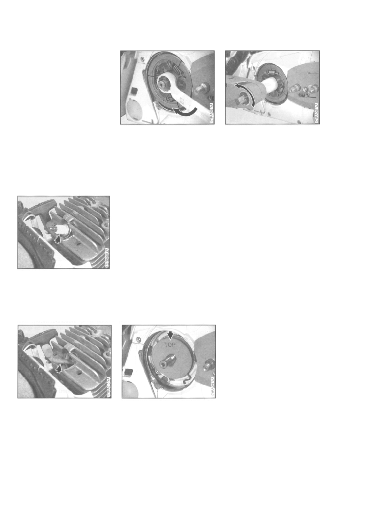
• Unscrew the spark plug.
• Unscrew the clutch from the
crankshaft in the direction of the
arrow (left-hand thread).
- Disassemble and reassemble the
clutch - see "Standard
Repairs, Troubleshooting"
handbook.
- Remove the cover washer.
• Screw clutch onto crankshaft and
torque down to 80 Nm
(59 Ibf.ft).
- Remove locking strip from
cylinder.
- Install spark plug and torque
down to 25 Nm (18.5 Ibf.ft).
Important: If spark plug has a
separate terminal nut, make sure that
it is properly tightened down.
- Install decompression valve
- see 4.8.
- Install clutch drum/chain
sprocket - see 3.1.
• Push the locking strip
0000 893 5903 into the cylinder.
• Fit cover washer so that "TOP"
faces outward.
STIHL 088 8
3.3 Chain Brake
y
3.3.1 Disassembl
- Remove clutch drum/chain
sprocket
- see 3.1.
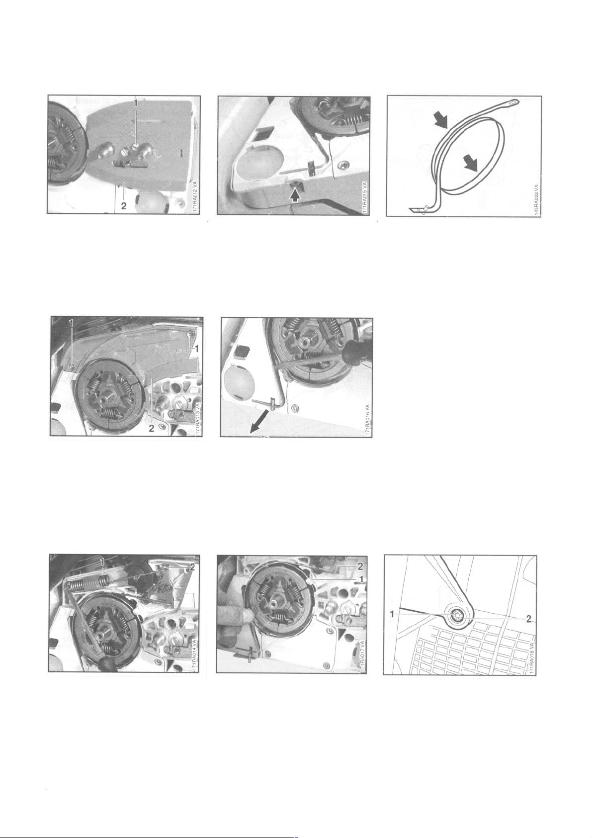
• Take out the screw (1).
• Remove the side plate (2).
- Relieve tension of brake spring
by pushing the hand guard
forward.
• Take out the screws (1).
• Take out the brake band
fastening screw.
• Lever the brake band out of the
crankcase.
Replace the brake band if:
- there are noticeable signs of wear
(large areas on inside diameter
and/or parts of outside diameter)
and
- its remaining thickness is < 0.6 mm
(0.024").
Important! Thickness of brake
band must not be less at any point.
• If the brake band is still serviceable, use No. 120 emery paper
or emery cloth (grain size
approx. 120µm) to clean and
roughen its entire friction surface
(inside diameter).
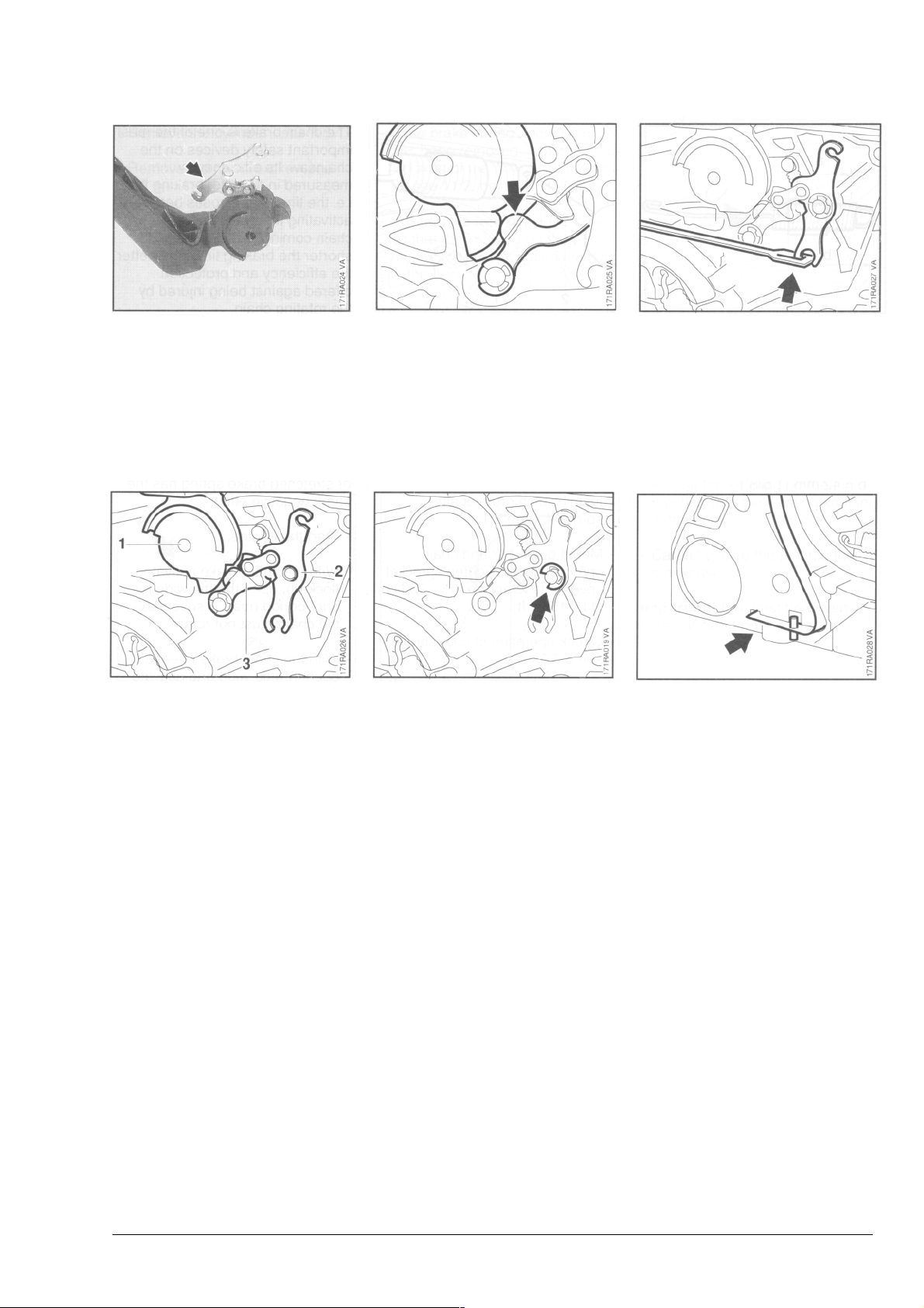
• Lift away the cover (2).
• Carefully pry the brake spring (1)
off the anchor pin and unhook it
from the bell crank (2).
• Remove the brake band from the
lugs (1) on the crankcase.
• Unhook the brake band from the
bell crank (2).
• Take out the screw (1).
• Remove the rubber bushing (2).
- Inspect parts and replace if
damaged.
STIHL 088 9
3.3.2
A
y
ssembl
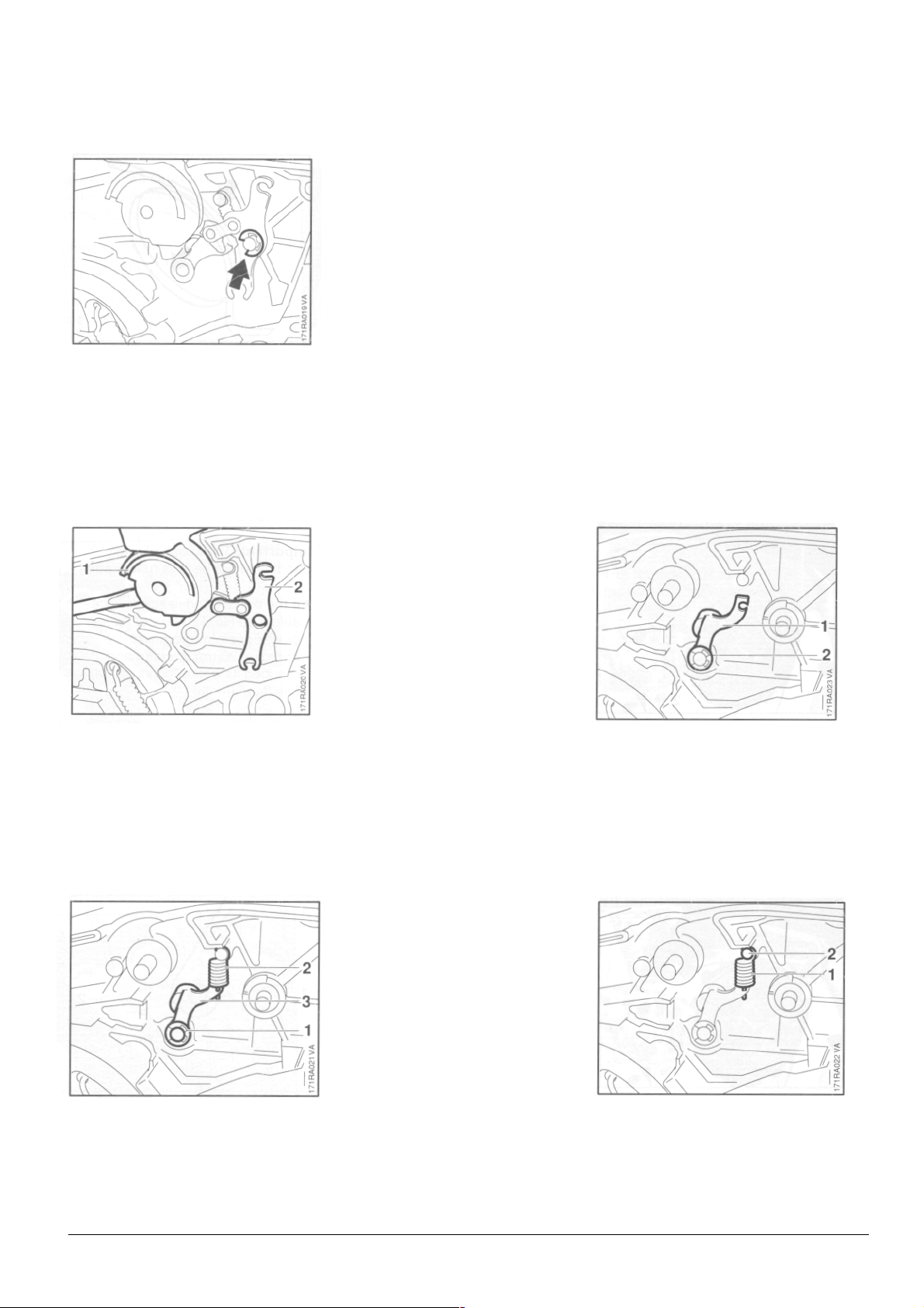
• Ease the E-clip off the bell crank
pivot pin.
• Unhook the spring (2) and take it
away.
• Pull off the cam lever (3).
- Inspect parts. Replace any worn
or damaged parts.
- Clean chain brake seat in crankcase.
- If the groove of the brake spring
anchor pin is worn, the anchor
pin must be replaced - see 3.3.4.
- Lubricate sliding and bearing
points of chain brake with STIHL
multipurpose grease or, preferably, Molykote grease - see 11.2.
• Carefully ease the hand guard
(1) and bell crank (2) off the pivot
pins and lift them away together.
- Pull the bell crank out of the
hand guard.
• Remove the E-clip (1).
• Push the cam lever (1) onto the
pivot pin.
• Fit the E-clip (2).
• Attach the spring (1) to the pivot
pin (2) and cam lever.
STIHL 088 10
• Insert the bell crank in the side
of the hand guard so that the
short arm of the bell crank points
up.
• Check that cam lever is properly
located on face of hand guard
bearing boss.
• Hook the brake spring onto the
bell crank.
- Position the brake band behind
the lugs on the crankcase.
• Position the hand guard (1)
against the pivot pin and fit the
other side of the hand guard over,
the housing.
• Position the bell crank (2)
against the pivot pin.
• Press the cam lever (3) slightly
downward and push the hand
guard and bell crank onto their
pivot pins.
- Push the metal bushing into the
back of the rubber bushing as far
as shoulder.
- Press the rubber bushing into the
hand guard.
- Fit hand guard mounting screw
and tighten to 7.0 Nm (5.2 Ibf.ft).
• Secure bell crank with E-clip.
- Coat brake band with chain oil
(STIHL Bioplus), see 11.2, to
protect it from corrosion and
cushion "snatching" during the
first few brake applications.
• Press brake band into slot.
- Coat the mounting screw with
Loctite, see 11.2. and torque
down to 3.0 Nm (2.2 Ibf.ft).
STIHL 088 11
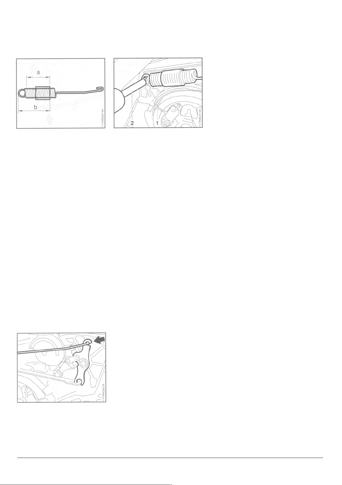
• Coils of brake spring must locate
tight against one another in
relaxed condition. Install a new
brake spring if necessary.
• Check that protective tube is
correctly positioned:
a = 20 mm (3/4")
b = 42 mm (1 5/8")
• Use the assembly tool (2)
1117 890 0900 to attach the
brake spring (1) to the anchor pin.
- Fit cover over the chain brake.
- Fit the side plate.
- Install clutch drum/chain
sprocket - see 3.1.
- Mount guide bar and chain
sprocket cover. Tighten sprocket
cover nuts to approx. 15 - 20 Nm
(11 - 15 Ibf.ft).
- Check operation of chain brake see 3.3.3.
3.3.3 Checking Function
The chain brake is one of the most
important safety devices on the
chainsaw. Its efficiency is
measured in terms of braking time,
i.e. the time that elapses between
activating the brake and the saw
chain coming to a standstill. The
shorter the braking time, the better
the efficiency and protection
offered against being injured by
the rotating chain.
Contamination (with chain oil,
chips, fine particles of abrasion,
etc.) and smoothing of the friction
surfaces of the brake band and
clutch drum impair the coefficient
of friction. This, in turn, reduces
the frictional forces and thus prolongs the braking time. A fatigued
or stretched brake spring has the
same negative effect.
- Start the engine.
- With the chain brake activated
(locked), open throttle wide for
- brief period (max. 3 seconds) the
chain must not rotate.
- With the chain brake released,
- open throttle wide and activate
- the brake manually - the chain
- must come to an abrupt stop.
• Attach the brake spring to the
bell crank.
Note: The braking time is in order
if deceleration of the saw chain is
imperceptible to the eye.
STIHL 088 12
3.3.4 Brake Spring Anchor Pin 3.3.5 Hand Guard Pivot
- Remove the cylinder - see 4.5.1.
- Remove the chain brake – see
3.3.1.
- If the brake spring anchor pin has
been removed, coat the knurled area of the new pin with Loctite, see 11.2, before installation.
- Position the new pin in the bore
so that the knurling on the pin
meshes with the existing knurling
in the bore.
• Use pliers to grip the pivot pin
and pull it out of the crankcase.
- Coat the knurled area of the new
pin with Loctite, see 11.2, before
installation.
- Position the new pin in the bore
so that the knurling on the pin
meshes with the existing knurling
in the bore.
- Carefully drive the pin into the
crankcase.
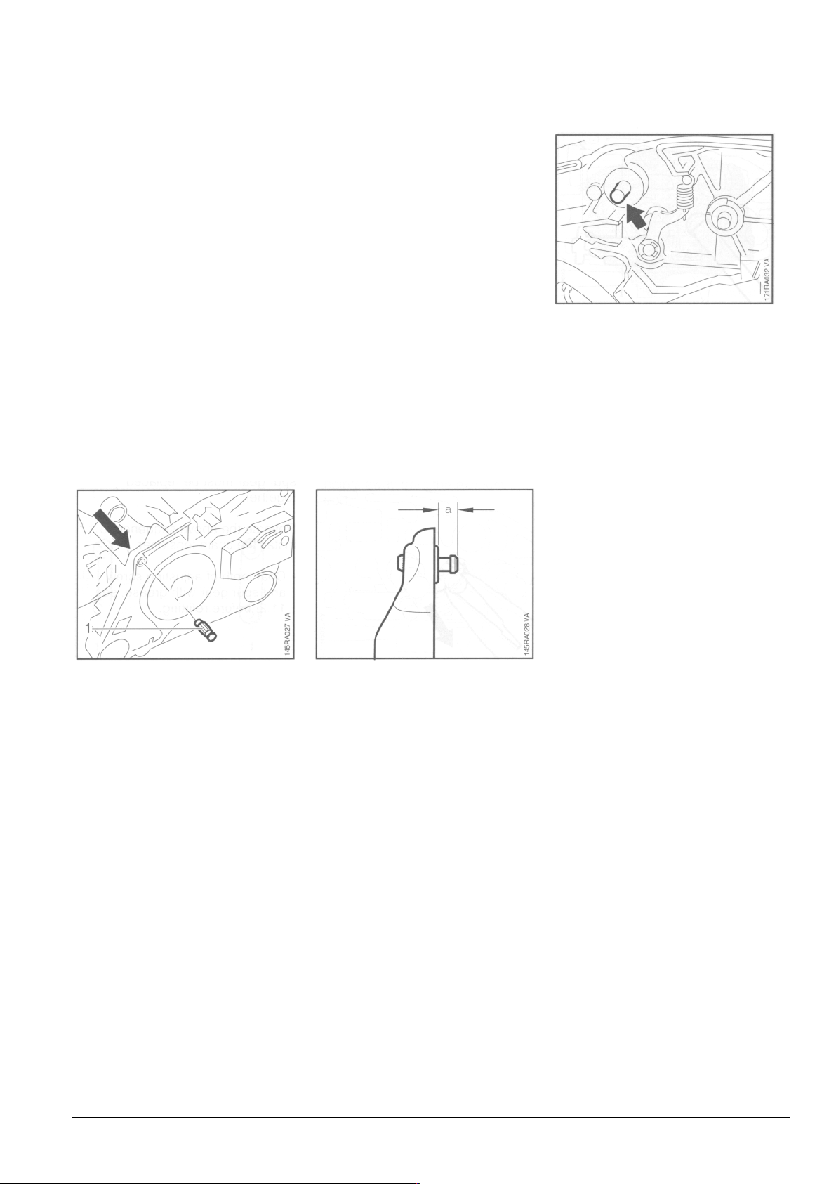
• Use a suitable punch to drive the
anchor pin out of the crankcase
in the direction of the arrow.
Important! Do not drive out the
pin in the other direction as this
would damage the annular bead
which was formed in the crankcase
bore when the pin was
originally installed.
In such a case neither the new
anchor pin nor the brake spring
would locate properly. Furthermore,
the crankcase could be damaged in
this way and possibly impair correct
operation of the chain brake.
Important! Pin must be driven
home at exact right angle.
• Carefully tap home the pin
squarely to obtain dimension
"a" = 4.3 - 4.7 mm (11/64").
Important! Pin must be driven home
at exact right angle.
- Install the cylinder - see 4.5.2.
- Install the chain brake - see
3.3.2.
STIHL 088 13

3.4 Chain Tensione
r
- Remove inner side plate - see
3.3.1.
• Rotate the spur gear clockwise
until the tensioner slide (1) butts
against the thrust pad (2).
• Take out the retainer (1).
• Take out the screw (2).
• Take out the brake washer.
• Pull out the spur gear.
• Inspect the teeth on the spur gear
and adjusting screw (1). If the teeth
are damaged, pull off the thrust pad
(2), take the adjusting screw out of
the tensioner slide (3) and replace
both parts.
Note: The adjusting screw and spur
gear must be replaced together.
Reverse the above sequence to install
the chain tensioner.
- Coat teeth of adjusting screw and
spur gear with grease, see 11.2,
before refitting.
• Remove the cover plate.
• Take out the tensioner slide with
adjusting screw and thrust pad.
• Check that O-ring is fitted in spur
gear and lubricate it with a little oil
before installing.
STIHL 088 14
4. ENGINE
p
4.1 Exhaust Muffler/S
Troubleshooting chart - see
"Standard Repairs, Troubleshooting"
handbook.
- Remove the shroud - see 4.8.
ark Arresting Screen
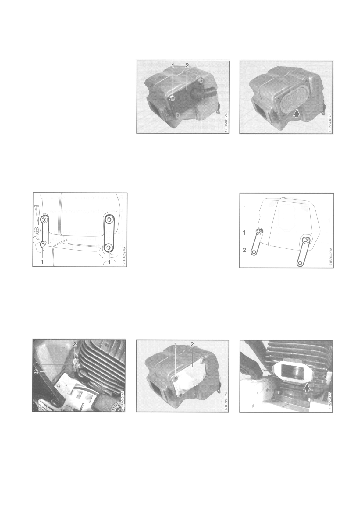
• Take out the screws.
Muffler without spark arresting
screen
• Take out the screws (1).
• Remove the cover (2).
- Fit the cover so that the stub
points away from the exhaust
port.
Muffler with spark
arresting screen
• Remove the spark arresting
screen.
- Clean the spark arresting screen
or fit a new one.
• Take out the screws (1)
• Remove the strap (2 )
• Ease away the clips (1).
• Remove the retainers (2).
• Remove the muffler (3).
• Take out the screws (1).
• Remove the cover (2).
• Remove the exhaust gasket.
Reassemble in the reverse
sequence.
STIHL 088 15
- Install a new exhaust gasket.
• Attach clip (1) to retainer (2).
- Tightening torques - see 2.6.
4.2 Leakage Test 4.2.1 Preparations
Defective oil seals and gaskets or
cracks in castings are the usual
causes of leaks. Such faults allow
supplementary air to enter the engine
and thus upset the fuel-air mixture.
This makes adjustment of the
prescribed idle speed difficult, if not
impossible.
Moreover, the transition from idle
speed to part or full throttle is not
smooth.
The crankcase can be checked
thoroughly for leaks with the
carburetor and crankcase tester and
the vacuum pump.
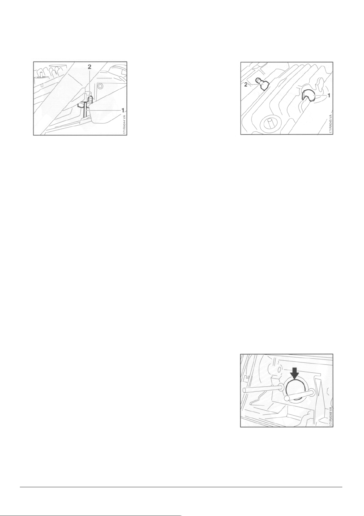
- Remove decompression valve
- see 4.8.
• Install plug (1) 1122 025 2200
and tighten to 14 Nm (10.3 Ibf.ft).
• Check that spark plug (2) is
properly tightened down.
- Remove the muffler - see 4.1.
- Remove the carburetor
- see 10.2.1.
- Set the piston to top dead center
(T.D.C.). This can be checked
through the intake port.
• Check that sleeve is in position.
STIHL 088 16
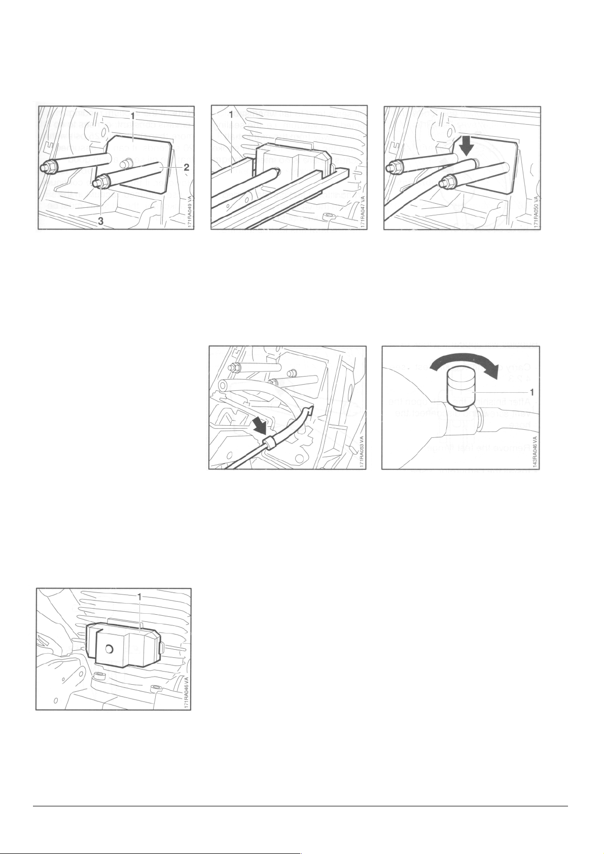
4.2.2 Pressure Test
• Push the test flange (1)
1106 850 4201 into position.
• Fit sleeves (2) 1127 851 8300.
• Fit nuts (3) and tighten down
firmly.
• Mount the clamp (1)
0000 890 4400.
• Seal the end of the impulse hose
with a pointed piece of round stock
(3 mm dia.) or a scriber.
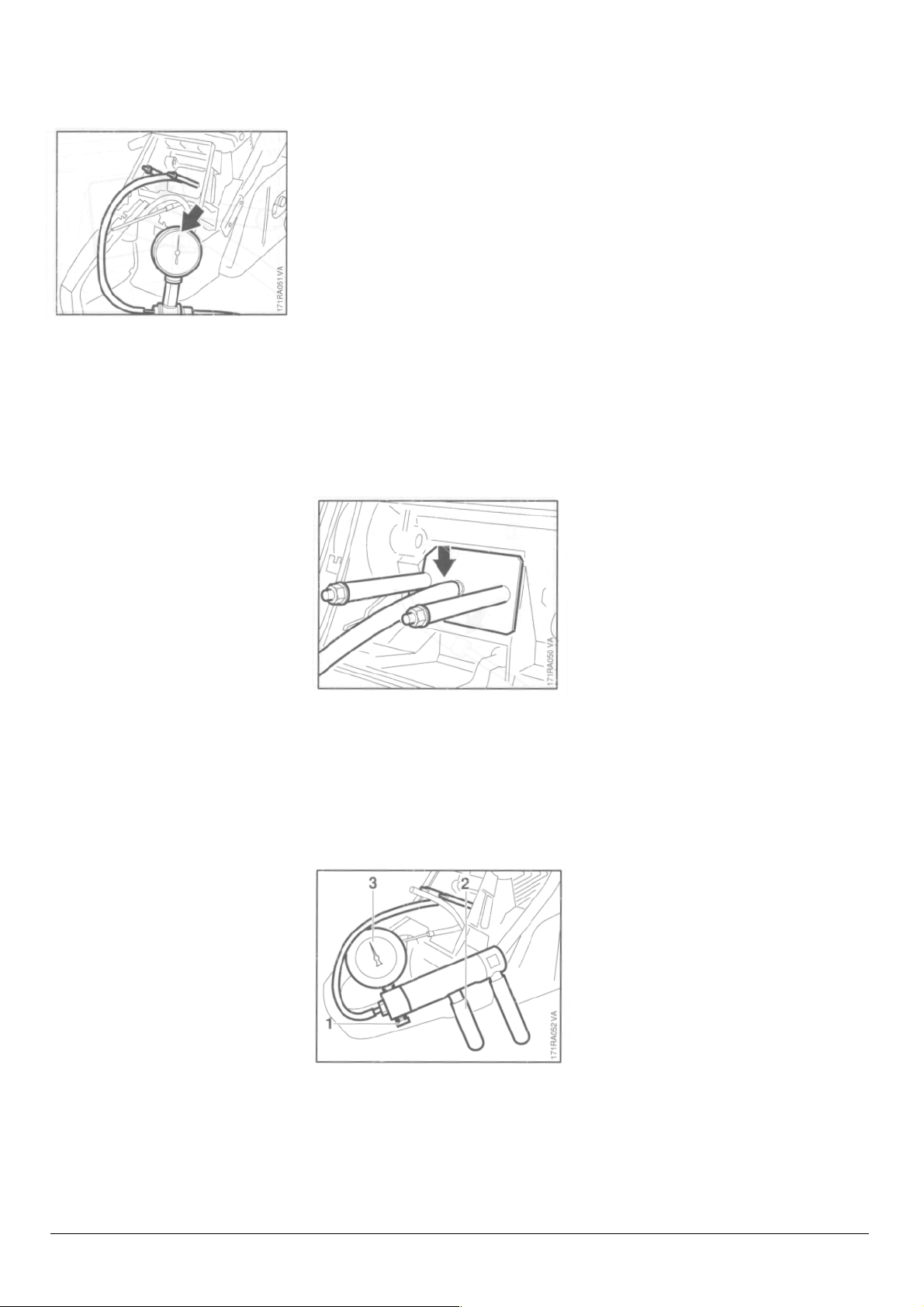
• Connect pressure hose of tester
1106 850 2905 to nipple on test
flange.
• Close the vent screw (1) on the
rubber bulb.
- Pump air into the crankcase with
rubber bulb until the gauge
indicates a pressure of 0.6 bar
(8.7 psi). If this pressure remains
constant for at least 20 seconds,
the crankcase is airtight.
• Fit the flange (1) 1124 850 4205 in
position.
STIHL 088 17
4.2.3
V
acuum Test
• However, if the indicated pressure
drops, the leak must be located
and the faulty part replaced.
Note: To find the leak, coat the
suspect area with oil and
pressurize the crankcase again.
Bubbles will appear if a leak exists.
- Carry out the vacuum test - see
4.2.3.
- After finishing the test, open the
vent screw and disconnect the
hose.
Oil seals tend to fail when subjected to
a vacuum, i.e. the sealing lip lifts away
from the crankshaft during the piston's
induction stroke because there is no
internal counterpressure.
An additional test can be carried out
with the vacuum pump to detect this
kind of fault. The preparations for this
test are the same as for the pressure
test see 4.2.2.
Note: !f the vacuum reading remains
constant, or rises to no more than 0.3
bar (4.25 psi) within 20 seconds, it can
be assumed that the oil seals are in
good condition.
However, if the pressure continues to
rise (reduced vacuum in the
crankcase), the oil seals must be
replaced.
- After finishing the test, open the
vent screw and disconnect the
hose.
- Remove the test flange.
- Install the carburetor
- see 10.2.1.
- Remove the test flange with clamp.
- Install the muffler - see 4.1.
- Unscrew the plug from the cylinder.
- Install decompression valve
- see 4.8.
- Remove the test flange.
- Install the carburetor - see 10.2.1.
- Remove the test flange with clamp.
- Install the muffler - see 4.1.
- Unscrew the plug from the cylinder.
- Install decompression valve see 4.8.
• Connect suction hose of vacuum
pump 0000 850 3501 to test
flange nipple.
• Close the vent screw (1) on the
pump.
• Operate lever (2) until pressure
gauge (3) indicates a vacuum of
0.4 bar (5.8 psi).
STIHL 088 18
 Loading...