

Page 1

DEUTSCH
D
Silent 40 El
8211-3427-04
Page 2
8x
4x
1x
2x
III
SVENSKA
S
AA
2 x (Ø 165 mm)
2 x (Ø 190 mm)
BB
2x
2x
4x
D
F
8x
C
4x
1. 2.
AA
2x (Ø 165 mm)
BB
2x
D
C
4x
2x (Ø 190 mm)
2x
F
8x
G
4x
E
III
L
O
2x
1x
O
1x
N
1x
L
4x
I
2x
M
4x
P
K
J
2x
I
2x
2x
P
1x
K
2x
R
2x
J
N
2x
M
2x
4.3.
Page 3
S
2
I
SVENSKA
I
L
∅ 165 mm
FF
A
P
M
1
4
2
5
11
∅ 190 mm
2
1
P
3
D
C
L
M
O
B
5.
II
Ø 165 mm
33
MM
4
L
4
L
4
5
1
F
1
EE
F
Ø 190 mm
G
6
2
3
I
K
5
J
7
K
5
I
J
D
C
N
6.
A
B
7.
Page 4

R
R
1
3
2
4
1 = 27 mm
II I
SVENSKA
S
1
OP
1
2 2
M
LL
M
33
II
I
K
4
J
K
4
I
J
5
N
8.
9.
III
1 = 28 mm
2 = 38 mm
3 = 48 mm
4 = 58 mm
2 = 37 mm
3 = 47 mm
4 = 57 mm
5 = 70 mm
4
5
4
5
3
2
1
10.
3
2
1
Page 5

S
I
I
II
SVENSKA
I
11.
II
12.
13.
Page 6

14.
SVENSKA
S
15.
Page 7

GB
ENGLISH
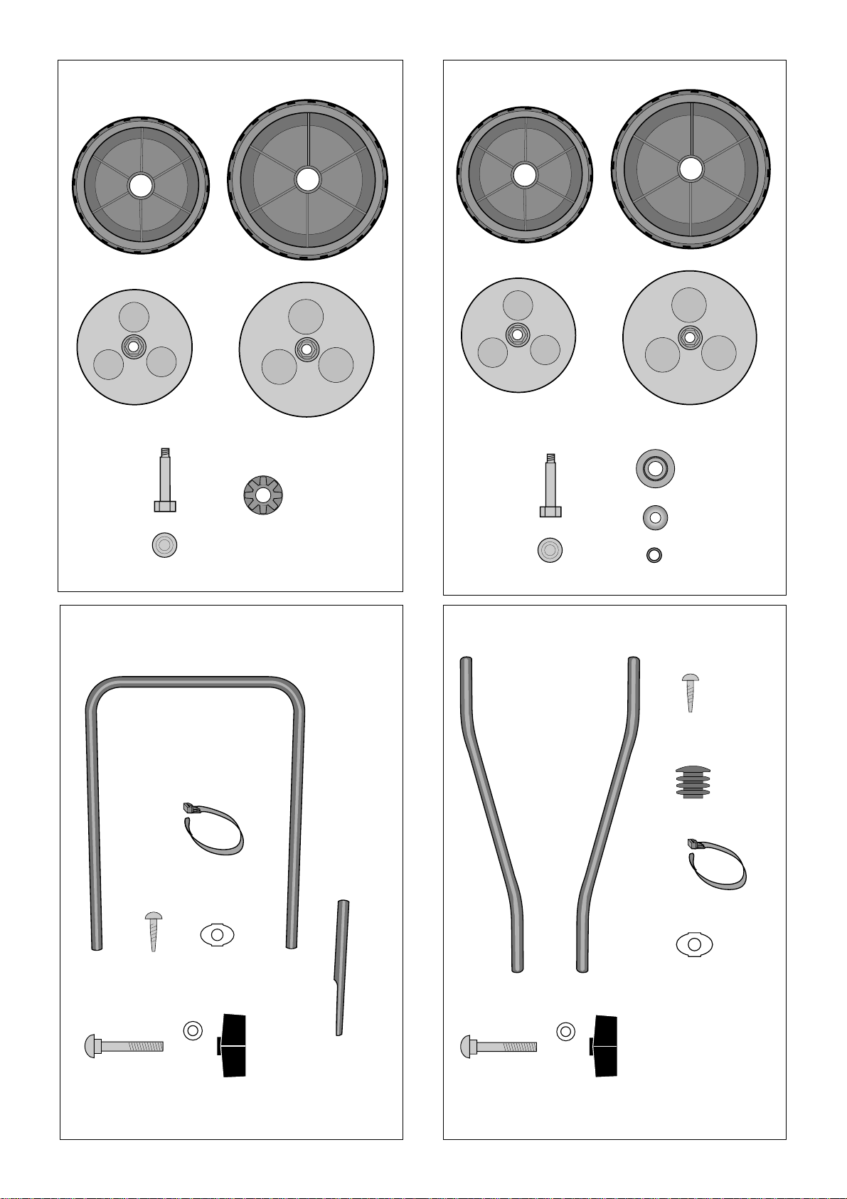
WHEELS type I (fig. 5)
SYMBOLS
1. Fit the bearings F in the wheel.
The following symbols are displayed on the machine in order to remind you about the safety precautions and attention necessary when using the
machine.
The symbols mean:
Warning! Read the Instruction Book and
Safety Manual before using the machine.
Warni ng! Keepspectatorsaway.Bewareof
objects being flung out.
Warning! Before starting any repair work,
disconnect the plug from the wall socket .
Warni ng! Keep the extension cord away
from the cutting deck.
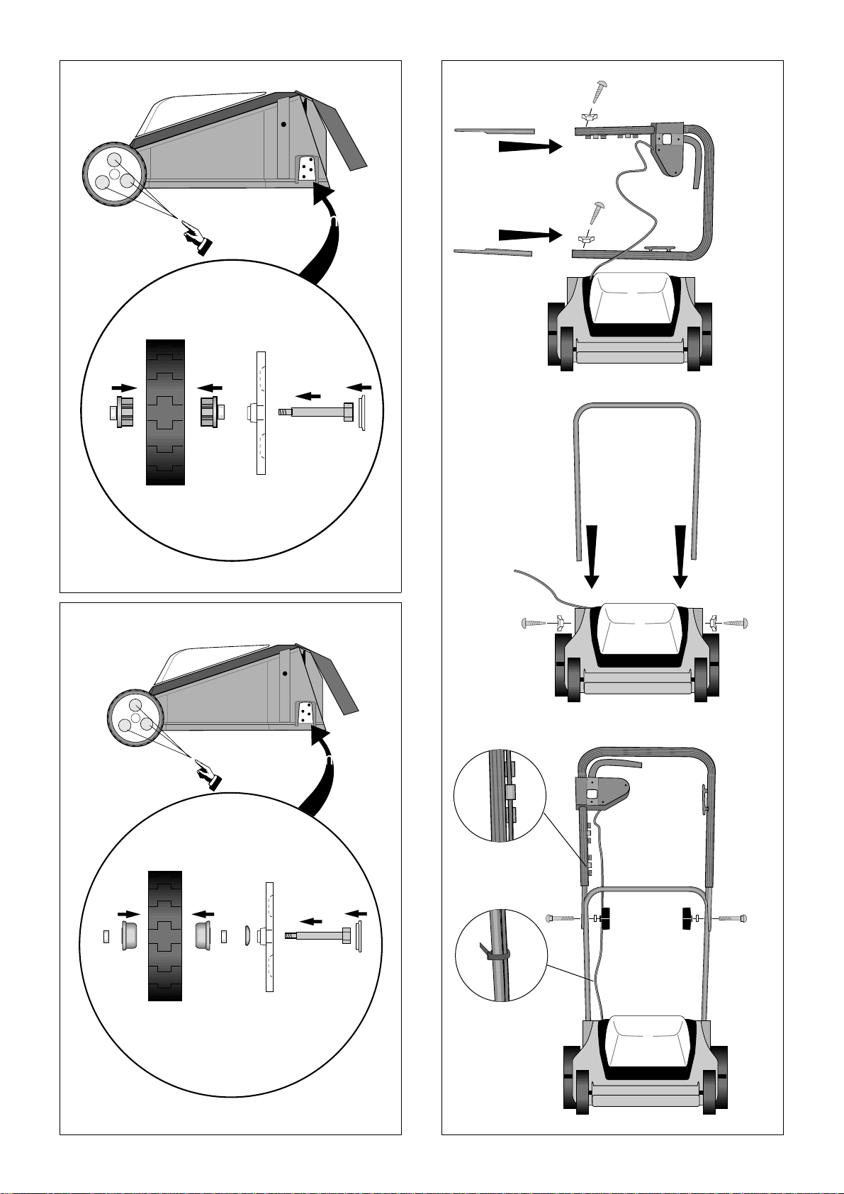
2. Apply the parts B, (F) and A on the wheel bolt.
3. Snap-on the centre cup C.
4. Fasten the wheel on the mower.
5. Tighten securely by hand using the finger-grip
holes in the hub cap.
WHEELS type II (fig. 6)
1. Fit the bearings F in the wheel.
2. Apply the parts B, G, E, (F) and A on the wheel
bolt.
3. Snap-on the centre cup C.
4. Fasten the wheel on the mower.
5. Tighten securely by hand using the finger-grip
holes in the hub cap.
STEERING type I (fig. 7)
1 . Insert the tubes into the ends of the handlebar.
Warning! Do not put hands orfeetunderthe
cover of the machine when it is running.
Warning! The blades continue to rotate
even after the machine has been switched
off.
STOP
ASSEMBLING
PARTS TO ASSEMBLE
Wheel type I (fig. 1)
Wheel type II (fig. 2)
Steering type I (fig. 3)
Steering type II (fig. 4)
TOOLS FOR ASSEMBLEY
2. Fit the screws. Tighten securely.
3. Insertthe ends of theU tube into the holes in the
chassis.
4. Fit the screws. Tighten securely.
5. Attach the handle to the U tube using the bolts,
washers and locking knobs provided. The handlebar can be folded forwards by undoing the
locking knobs slightly. This reduces the space
the mower takes up during transport, etc.
6. Secure the electrical cable into the cable holder.
7. Fix the electrical cable using a cable tie.
STEERING type II (fig. 8)
1. Press the plugs intothe steering sockets. Ensure
that the plugs are inserted in the correct end.
2. Press the steering sockets into the holes in the
chassis.
3. Fit the screws. Tighten securely.
4. Attach the handlebar to the steering sockets using screws, washers and locking knobs. The
handlebar can be tilted forward by loosening
the locking knobs slightly. The mower willthen
take up less space during transportation.
5. Fix the electrical cable using a cable tie.
Page 8

ENGLISH
GB
GRASS COLLECTOR (fig. 9)
Fabriccollectorbin: Pull the fabric collector bag
over the steel frame and snap the bag on the plastic
cover.
Plastic collector bin: Snapthe twohalves together
and then the upper part.
Open the cover on the machine and hook the grass
collector onto the chassis.
Note! The lawn mower can be used without the
grass collector. The grass will then collect in a
bead behind the machine.
USING THE MOWER
CUTTING HEIGHT (fig. 10)
Depending on the model, the cutting height is adjusted as follows:
I. Fasten the wheels in one of the four possible po-
sitions.
CUTTING (fig. 13)
Always cut away from the cable.
Empty the grass collector in good time so that the
grass deflector does not get blocked and reduce
grass collection capacity.
To avoid overloading the motor, do not push the
mower too quickly in long grass.
MAINTENANCE
CHANGING BLADES (fig. 14)
Alwayspullout theplugbeforecarrying
out maintenance, cleaning or other actions on the machine.
Wear protective gloves. Loosen the blade bolts using a 26 mm spanner. Fit a new blade. Tightening
torque 22 Nm.
Always use genuine spare parts.
CLEANING AND STORAGE (fig. 15)
II. Set the height adjustment lever to the desired
position.
Note! The same cutting height should be set on all
four wheels.
CONNECTION (fig. 1 1)
Only use an extension cable approved for outdoor
use. If uncertain please contact your dealer.
To increase safety the lawn mower should be connected to an earth-fault breaker.
Supportthe extension cablein the cable support on
the steering.
START/STOP (fig. 12)
Start the mower on flat, solid ground. Do not start
in longgrass. Press on the steering so that the front
wheels lift slightlyfrom the ground to reduce grass
resistance.
Always wipe or brush off the mower after use.
The cold air intakearound the motor casingshould
always be kept free from grass and dirt so that the
motor does not overheat.
The underside of the chassis can be scraped clean.
Never rinse with water.
The mower should be stored in the dry.
Starting the motor:
1. Press the button
2. Pull the handle towards the steering.
Stopping the motor: Release the handle.
 Loading...