


INSTALLATION AND SERVICE MANUAL
OUTDOOR ROOFTOP GAS-FIRED DUCT FURNACE
(NATURAL OR POWER VENTED)
RISM-14 J30-05380
ATTENTION: READ THIS MANUAL AND ALL LABELS ATTACHED TO THE UNIT CAREFULLY BEFORE ATTEMPTING TO INSTALL, OPERATE OR SERVICE THESE UNITS! CHECK UNIT DATA PLATE FOR TYPE OF GAS AND ELECTRICAL SPECIFICATIONS AND MAKE CERTAIN THAT THESE AGREE WITH THOSE AT POINT OF INSTALLATION. RECORD THE UNIT MODEL AND SERIAL No.(s) IN THE SPACE PROVIDED. RETAIN FOR FUTURE REFERENCE.
Unit No. |
|
Serial No. |
SAVE THIS MANUAL
FOR YOUR SAFETY
The use and storage of gasoline or other flammable vapors and liquids in open containers in the vicinity of this appliance is hazardous.
FOR YOUR SAFETY
If you smell gas:
1.Don’t touch electrical switches.
2.Extinguish any open flame.
3.Immediately call your gas supplier.


 Improper installation, adjustment, alteration, service or maintenance can cause property damage, injury or death. Read the installation, operating and maintenance instructions thoroughly before installing or servicing this equipment.


 Install, operate and maintain unit in accordance with manufacturer's instructions to avoid exposure to fuel substances or substances from incomplete combustion which can cause death or serious illness. The state of California has determined that these substances may cause cancer, birth defects, or other reproductive harm.
INSTALLER'S RESPONSIBILITY
Installer Please Note: This equipment has been test fired and inspected. It has been shipped free from defects from our factory. However, during shipment and installation, problems such as loose wires, leaks or loose fasteners may occur. It is the installer's responsibility to inspect and correct any problems that may be found.
These units are certified by ETL for operation on either natural or propane gas.
Read this manual and all labels attached to the unit carefully before attempting to install, operate or service the following unit models:*
Outdoor Rooftop Duct Furnaces: QV(RT/PV)- (100, 150, 200, 250, 300, 350, 400) (H)(M)
(RT = Natural Vent; PV = Power Vent)
*Look in the direction of the unit air flow to determine whether the unit is right or left-hand accessible.
|
|
|
|
|
|
|
|
|
|
|
|
|
|
|
|
260 NORTH ELM ST., WESTFIELD, MA 01085 |
||||
|
|
TEL: (413) 568-9571 FAX: (413) 562-8437 |
||||
04/13 |
|
www.mestek.com |
||||
|
||||||
|
|
|
|
|
|
|

TABLE OF CONTENTS |
|
RECEIVING/PRE-INSTALLATION |
|
INSTRUCTIONS...................................................... |
2 |
GENERAL SAFETY INFORMATION.................... |
2, 3 |
SPECIFICATIONS |
|
Dimensional Data.......................................... |
4, 5 |
Performance and Specifi cation Data................. |
5 |
Performance Data Curves............................. |
6, 7 |
INSTALLATION |
|
Location/Mounting..................................... |
2, 3, 8 |
Clearances ................................................ |
4, 5, 8 |
Venting .............................................................. |
9 |
Duct and Drain Specifi cations ......................... |
10 |
Gas Connections................................. |
10, 11, 12 |
Electrical Connections..................................... |
12 |
OPERATION |
|
General Information................................... |
13, 14 |
Intermittent Pilot Ignition Parts ........................ |
13 |
Controls........................................................... |
14 |
Gas Controls ................................................... |
15 |
Air Distribution/Throughput ............................. |
16 |
Lighting...................................................... |
17, 18 |
Primary Air Shutter/Pilot Adjustment............... |
18 |
Gas Input Adjustment...................................... |
18 |
START-UP............................................................... |
19 |
MAINTENANCE ............................................... |
20, 21 |
TROUBLESHOOTING GUIDE .......................... |
22-25 |
REPLACEMENT PARTS ........................................ |
26 |
WARRANTY ........................................................... |
26 |
GAS EQUIPMENT CHECK SHEET ....................... |
28 |
The following terms are used throughout this manual to bring attention to the presence of potential hazards or to important information concerning the product:


 Indicates an imminently hazardous situation which, if not avoided, will result in death, serious injury or substantial property damage.


 Indicates an imminently hazardous situation which, if not avoided, could result in death, serious injury or substantial property damage.


 Indicates an imminently hazardous situation which, if not avoided, may result in minor injury or property damage.
NOTICE: Used to notify of special instructions on installation, operation or maintenance which are important to equipment but not related to personal injury hazards.
SERVICE ACCESS PANEL REMOVAL
To remove an access panel door, use the following procedure: remove the two screws and two washers from the louvered flue discharge area of the service panel (power vent doors only). Each panel is held in place with two “Grip” Latches. Using a slotted head screw driver, turn the latch screwhead counter clockwise. Using the handle provided, pull the panel upwards. Pull the bottom of the panel out and lower the panel to disengage it from the top lip. To replace an access door panel, guide the panel door upwards
on the tracks, and push up into the top lip; swing and lower the panel in place until it engages with the bottom panel. Turn the screwhead on each latch clockwise. The screw must turn freely one quarter turn before resistance is felt in order for the lock to engage. If the latch does not hold, turn the screw counter-clockwise several turns and repeat the above procedure. Also refer to Figures 8a, 8b and 8c for more specifi cations.
RECEIVING INSTRUCTIONS
Inspect shipment immediately when received to determine if any damage has occurred to the carton/ crate during shipment.
After the unit has been uncrated, check for any visible damage to the unit. On power vented units, check motor position and turn blower wheel by hand to determine if damage has occurred to these critical parts.
If any damage is found, the consignee should sign the bill of lading indicating such damage and immediately fi le claim for damage with the transportation company.
PRE-INSTALLATION INSTRUCTIONS
When unit is received and uncrated check data plate on unit for type of gas and electrical specifi cations and make certain that these agree with those at point of installation.


 Open all disconnect switches and secure in that position before installing the unit. Failure to do so may result in personal injury or death from electrical shock.
NOTICE: It is the equipment owner’s responsibility to provide any scaffolding or other apparatus required to perform emergency service or annual/ periodic maintenance to this equipment.
RIGGING
Rig the unit using either belt or cable slings. Use spreader bar to protect the top of the unit when it is lifted.
The furnace units are provided with two holes in the base rail on each side of the unit. Slide pipes beneath the unit through these holes and attach rigging to the pipes for lifting the unit.
LOCATION
Before placing the rooftop unit in its permanent location, make certain that the roof is capable of carrying the additional load of this equipment. Check the shipping weights given in Chart 2.
Refer to Figures 1, 2 and 6 and charts 1 and 2 for adequate unit dimensions and required clearances.
MOUNTING
The units are mounted on skids and are suitable for use on combustible fl ooring. It is recommended that the skids be mounted either on level solid planking or steel channels, but never on a soft tar roof where the skids could sink and reduce the clearance between the bottom panel and the roof.
– 2 –

GENERAL SAFETY INFORMATION
Roofcurb kits for rooftop gas heating units are shipped knocked down. A curb kit contains (insulated) curb rails, hardware, sealant, self-adhering rubber gasketing, and installation instructions. Roof insulation, cant strips, flashing, roof felts, caulking and nails must be furnished by the installer. See separate curb specifi cations from manufacturer.


 Failure to comply with the general safety information may result in extensive property damage, severe personal injury or death!


 This product must be installed by a licensed plumber or gas fitter when installed within the Commonwealth of Massachusetts.


 Do not alter the unit heater in any way or damage to the unit and/or severe personal injury or death may occur!


 Never service any component without first disconnecting all electrical and gas supplies to the unit or severe personal injury or death may occur!


 Ensure that all power sources conform to the requirements of the unit heater or damage to the unit will result!
Installation must be made in accordance with local codes, or in absence of local codes, with the latest edition of ANSI Standard Z223.1 (NFPA No. 54) National Fuel Gas Code. All of the ANSI and NFPA Standards referred to in these installation instructions are those that were applicable at the time the design of the appliance was certified. The ANSI Standards are available from the American National Standards Institute, Inc., 11 West 42nd Street, New York, NY, 10036 or www.ansi.org. The NFPA Standards are available from the National Fire Protection Association, Batterymarch Park, Quincy, MA 02269.
If installed in Canada, the installation must conform with local building codes, or in absence of local building codes, with current CSA-B149.1 “Installation Codes for Natural Gas Burning Appliance and Equipment” or CSA-B149.2 “Installation Codes for Propane Gas Burning Appliances and Equipment”. These outdoor duct furnaces have been designed for and certifi ed to comply with CSA 2.8.
These units have been designed and certified for outdoor use only, and may be located on the roof of the building or at any convenient location external of the building to be heated. The input range is 100,000 BTU/HR. (29.3 kW) to 400,000 BTU/HR. (117.1 kW) in 50,000 BTU/HR. (14.6 kW) increments.
The venting is an integral part of the unit and must not be altered in the field. The Natural Vented units are equipped with a vent cap which is designed for gravity venting. Air for combustion enters at the base of the vent through a protective grille, and the design of the vent cap is such that the products of combustion are discharged at the upper section of the cap. This cap is shipped in a separate carton. It should be fastened in position as shown in Figure 7 and should not be altered in any way.
The Power Vented unit has a power venting system with the inlet and discharge grille located in the upper section of the side access panel. This balanced flue design also preforms well under all wind conditions.
All internal parts of the standard unit are fabricated from aluminized steel. Standard burners are pressed aluminized steel and have a stainless steel burner port protector and air shutters. All internal and external jacket parts are fabricated from galvanized steel. Stainless steel heat exchangers, burners and flue collectors are optional. An optional 321 or 409 stainless steel heat exchanger is highly recommended for the following applications:
1)When the entering air temperature is below 40°F (4.4°C),
2)When the furnace is installed downstream of a cooling coil section.
A pilot burner plate is provided for access to the pilot burner and ignition systems without removing the burner drawer. Clearances between the external unit and obstruction must be sufficient for proper servicing of pull-out drawer. See Figures 1 and 2 for this clearance.
The outdoor units are certified for operation on either natural or propane gas. If a unit is to be installed at an altitude exceeding 2000 ft. (610 m) above sea level, derate the input by 4% for each 1000 foot rise (305 m rise) above sea level. Check all local codes.
Special orifices are required for installations above 2000 ft. (610 m). Check all local codes.
In Canada, if a unit is to be installed at altitudes of 2000 ft. (610 m) to 4500 ft. (1372 m), the unit must be orificed to 90% of the normal altitude rating.
Unless otherwise specifi ed, the following conversions may be used for calculating SI unit measurements:
1 inch = 25.4 mm |
1000 Btu/Cu. Ft. = 37.5 MJ/m3 |
1 foot = 0.305 m |
1000 Btu per hour = 0.293 kW |
1 gallon = 3.785 L |
1 inch water column = 0.249 kPa |
1 pound = 0.454 kg |
liter/second = CFM x 0.472 |
1 psig = 6.894 kPa |
meter/second = FPM ÷ 196.8 |
1 cubic foot = 0.028 m3
– 3 –
SPECIFICATIONS
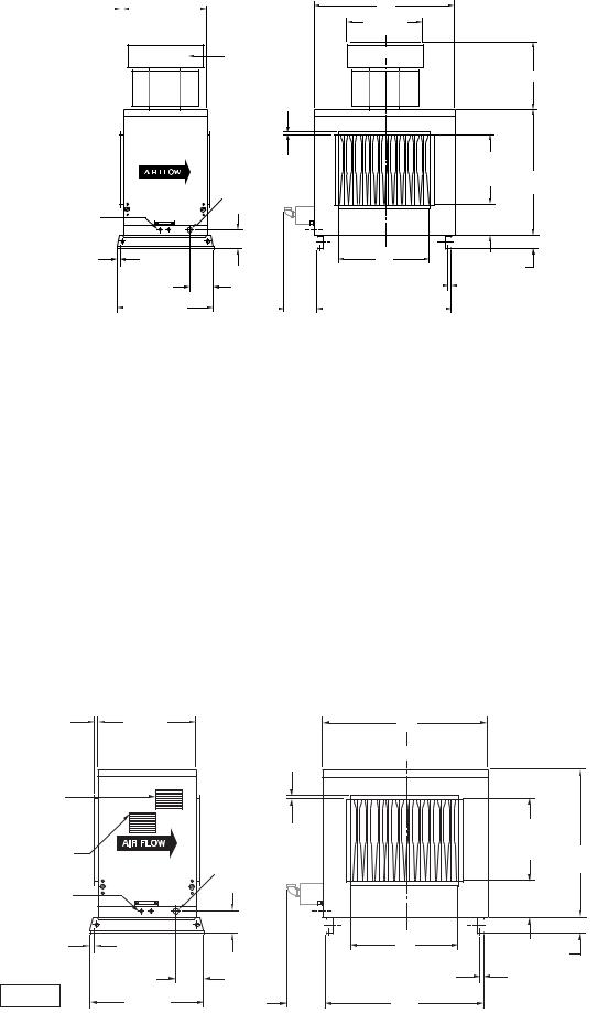
Figure 1 - Standard Natural Vented Outdoor Duct Furnace
1" (25) |
|
|
|
|
|
26" |
|
|
||
Typ. |
|
|
|
|
|
(660) |
|
|
||
|
|
|
|
|
|
|
|
|
|
|
|
|
|
|
|
|
|
|
|
|
|
|
|
|
|
|
|
|
|
|
|
|
|
|
|
|
|
|
|
|
|
|
|
|
|
|
|
|
|
|
|
|
|
|
Electrical
Connections
5/8" (16) Typ.
Anchor Hole
Location
DFR3538A |
|
|
|
|
|
31-1/4" |
|
TFR3779A |
|
||
|
|
(794) |
|
|
|
||
|
A |
|
|
|
|
C (Typ.) |
|
|
|
Vent Cap |
|
|
|
|
Is Shipped |
C |
|
|
|
In Separate |
L |
|
|
|
Carton |
|
|
|
D |
|
|
|
|
|
1-1/8" (29) |
|
|
19" |
|
|
|
(483) |
|
|
Typ. Duct |
|
|
39" |
|
Flange |
|
|
Opening |
|
Gas |
|
|
|
(991) |
Connection |
|
|
|
|
|
|
|
|
|
|
|
|
10-1/8" |
|
|
|
|
(257) |
|
5-1/16" |
|
|
|
|
(129) |
|
|
|
|
|
B |
|
4" (102) |
|
|
Opening |
Typ. |
||
8-3/4" |
|
|
|
|
|
|
|
|
|
13/16" (21) Typ. |
(222) |
* |
|
|
|
|
|
|
|
Anchor Hole |
|
|
|
|
|
|
|
|
|
Location |
||
|
|
F |
|
K |
|
|
|
|
|
|
|
|
|
|
|
|
|
|
|
||
|
|
|
|
|
|
|
|
|
|
|
Chart 1 - Dimensional/Data
CAPACITY |
|
|
|
US |
CANADA |
|
|
GAS INLET |
|
(CA) |
A |
B |
C |
D |
D |
*F |
K |
NAT |
LP |
10 |
32-7/8 |
15-9/16 |
12 |
11 |
20-11/16 |
19-3/8 |
30-3/16 |
1/2 |
1/2 |
|
(835) |
(395) |
(305) |
(279) |
(525) |
(492) |
(767) |
|
|
15 |
32-7/8 |
18-5/16 |
21-1/2 |
16 |
25-3/16 |
23-1/2 |
30-3/16 |
1/2 |
1/2 |
|
(835) |
(465) |
(546) |
(406) |
(640) |
(597) |
(767) |
|
|
20 |
43-7/8 |
23-13/16 |
23-1/2 |
16 |
25-3/16 |
26-1/4 |
41-3/16 |
1/2 |
1/2 |
|
(1114) |
(605) |
(597) |
(406) |
(640) |
(667) |
(1046) |
|
|
25 |
43-7/8 |
29-5/16 |
23-1/2 |
16 |
25-3/16 |
34-1/2 |
41-3/16 |
3/4 |
1/2 OR 3/4 |
|
(1114) |
(745) |
(597) |
(406) |
(640) |
(876) |
(1046) |
|
|
30 |
54-7/8 |
34-13/16 |
26 |
17-1/2 |
26-11/16 |
37-1/4 |
52-3/16 |
3/4 |
1/2 OR 3/4 |
|
(1394) |
(884) |
(660) |
(445) |
(678) |
(946) |
(1326) |
|
|
35 |
54-7/8 |
40-5/16 |
26 |
17-1/2 |
26-11/16 |
45-1/2 |
52-3/16 |
3/4 |
1/2 OR 3/4 |
|
(1394) |
(1024) |
(660) |
(445) |
(678) |
(1156) |
(1326) |
|
|
40 |
60-3/8 |
45-13/16 |
26 |
17-1/2 |
26-11/16 |
51 |
57-11/16 |
3/4 |
1/2 OR 3/4 |
|
(1534) |
(1164) |
(660) |
(445) |
(678) |
(1295) |
(1465) |
|
|
NOTE:
DIMENSIONS ARE IN INCHES, DIMENSIONS IN PARENTHESIS ARE IN MILLIMETERS.
*“F” DIMENSION IS THE RECOMMENDED CLEARANCE TO SERVICE THE BURNER DRAWER(S). REFER TO FIGURE 6 FOR ADDITIONAL CLEARANCE REQUIREMENTS.
Figure 2 - Standard Power Vented Outdoor Duct Furnace
1" (25) |
26" |
|
|
A |
|
|
Typ. |
(660) |
|
|
|
|
|
|
|
|
|
|
||
|
|
|
|
C |
|
|
|
|
|
|
L |
|
|
Flue |
|
|
|
|
|
|
Product |
|
|
|
|
|
|
Outlet |
|
|
|
|
|
|
|
|
|
1-1/8" (29) |
|
19" |
|
Combustion |
|
|
Typ. Duct |
|
(483) |
|
|
Gas |
Flange |
|
Opening |
39" |
|
Air Inlet |
|
|
|
|
(991) |
|
|
|
Connection |
|
|
|
|
|
|
|
|
|
|
|
Electrical |
|
|
|
|
10-1/8" |
|
Connections |
|
|
|
|
|
|
|
|
|
|
(257) |
|
|
|
|
|
|
|
|
|
|
|
5-1/16" |
|
|
|
|
|
|
(129) |
|
|
|
|
5/8" (16) Typ. |
|
|
|
B |
|
|
Anchor Hole |
|
|
|
Opening Typ. |
4" (102) |
|
Location |
|
|
|
|
|
|
|
8-3/4" |
|
|
13/16" (21) Typ. |
||
|
|
|
|
|||
DFR3541A |
|
(222) |
* |
|
Anchor Hole |
|
31-1/4" |
|
|
Location |
|
||
TFR3779 A |
|
F |
K |
|
||
(794) |
|
|
|
|||
|
|
|
|
|
|
|
– 4 –
Chart 2 - Performance and Specification Data
|
|
|
|
|
|
|
|
|
|
|
F* |
NG |
LP |
|
|
|
|
|
INPUT |
OUTPUT |
|
|
|
Temp. Rise |
|
Min. |
Gas |
Gas |
Net |
Shipping |
|||
|
CAPACITY |
RATING |
RATING |
EFF. |
MIN. |
MAX. |
|
°F |
|
Static |
Clearance |
Inlet |
Inlet |
Weight |
Weight |
|
|
MBH |
BTU/Hr |
BTU/Hr |
% |
CFM |
CFM |
(°C) |
in. of Water |
in. |
in. |
in. |
lb. |
lb. |
|||
|
|
(kW) |
(kW) |
|
(cu. m/s) |
(cu. m/s) |
Min. |
- |
Max. |
(KPa) |
(mm) |
|
|
(kg) |
(kg) |
|
|
|
|
|
|
|
|
|
|
|
|
|
|
|
|
|
|
** |
100 |
100,000 |
80,000 |
80 |
823 |
2,469 |
30 |
- |
90 |
2 |
7-1/8 |
1/2 |
1/2 |
256 |
367 |
|
|
(29.3) |
(23.4) |
|
(0.388) |
(1.165) |
(17) |
- |
(50) |
(0.50) |
(181) |
|
|
(116) |
(166) |
||
|
|
|
|
|
||||||||||||
|
150 |
150,000 |
120,000 |
80 |
1,235 |
3,704 |
30 |
- |
90 |
2 |
11-1/4 |
1/2 |
1/2 |
307 |
418 |
|
|
|
(43.9) |
(35.1) |
|
(0.583) |
(1.748) |
(17) |
- |
(50) |
(0.50) |
(286) |
|
|
(139) |
(190) |
|
VENT |
200 |
200,000 |
160,000 |
80 |
1,646 |
4,938 |
30 |
- |
90 |
2 |
14 |
1/2 |
1/2 |
365 |
484 |
|
|
(58.6) |
(46.9) |
|
(0.777) |
(2.331) |
(17) |
- |
(50) |
(0.50) |
(356) |
|
|
(166) |
(220) |
||
|
|
|
|
|
||||||||||||
NATURAL |
250 |
250,000 |
200,000 |
80 |
2,058 |
6,173 |
30 |
- |
90 |
2 |
22-1/4 |
3/4 |
1/2 OR 3/4 |
405 |
524 |
|
|
(73.2) |
(58.6) |
|
(0.971) |
(2.913) |
(17) |
- |
(50) |
(0.50) |
(565) |
|
|
(184) |
(238) |
||
|
|
|
|
|
||||||||||||
|
300 |
300,000 |
240,000 |
80 |
2,469 |
7,407 |
30 |
- |
90 |
2 |
34 |
3/4 |
1/2 OR 3/4 |
469 |
596 |
|
|
|
(87.8) |
(70.3) |
|
(1.165) |
(3.496) |
(17) |
- |
(50) |
(0.50) |
(864) |
|
|
(213) |
(270) |
|
|
350 |
350,000 |
280,000 |
80 |
2,881 |
8,642 |
30 |
- |
90 |
2 |
33-1/4 |
3/4 |
1/2 OR 3/4 |
510 |
637 |
|
|
|
(102.5) |
(82.0) |
|
(1.360) |
(4.079) |
(17) |
- |
(50) |
(0.50) |
(845) |
|
|
(231) |
(289) |
|
|
400 |
400,000 |
320,000 |
80 |
3,292 |
9,876 |
30 |
- |
90 |
2 |
38 3/4 |
3/4 |
1/2 OR 3/4 |
558 |
690 |
|
|
|
(117.1) |
(93.7) |
|
(1.554) |
(4.661) |
(17) |
- |
(50) |
(0.50) |
(984) |
|
|
(253) |
(313) |
|
|
|
|
|
|
|
|
|
|
|
|
|
|
|
|
|
|
** |
100 |
100,000 |
80,000 |
80 |
823 |
2,469 |
30 |
- |
90 |
2 |
7-1/8 |
1/2 |
1/2 |
262 |
373 |
|
|
(29.3) |
(23.4) |
|
(0.388) |
(1.165) |
(17) |
- |
(50) |
(0.50) |
(181) |
|
|
(119) |
(169) |
||
|
|
|
|
|
||||||||||||
VENT |
150 |
150,000 |
120,000 |
80 |
1,235 |
3,704 |
30 |
- |
90 |
2 |
11-1/4 |
1/2 |
1/2 |
298 |
409 |
|
200 |
200,000 |
160,000 |
80 |
1,646 |
4,938 |
30 |
- |
90 |
2 |
14 |
1/2 |
1/2 |
356 |
475 |
||
POWER |
|
(43.9) |
(35.1) |
|
(0.583) |
(1.748) |
(17) |
- |
(50) |
(0.50) |
(286) |
|
|
(135) |
(186) |
|
|
(58.6) |
(46.9) |
|
(0.777) |
(2.331) |
(17) |
- |
(50) |
(0.50) |
(356) |
|
|
(161) |
(215) |
||
|
|
|
|
|
||||||||||||
|
250 |
250,000 |
200,000 |
80 |
2,058 |
6,173 |
30 |
- |
90 |
2 |
22-1/4 |
3/4 |
1/2 OR 3/4 |
395 |
514 |
|
|
|
(73.2) |
(58.6) |
|
(0.971) |
(2.913) |
(17) |
- |
(50) |
(0.50) |
(565) |
|
|
(179) |
(233) |
|
|
350 |
325,000 |
260,000 |
80 |
2,675 |
8,025 |
30 |
- |
90 |
2 |
33-1/4 |
3/4 |
1/2 OR 3/4 |
495 |
622 |
|
|
|
(95.2) |
(76.2) |
|
(1.263) |
(3.789) |
(17) |
- |
(50) |
(0.50) |
(845) |
|
|
(225) |
(282) |
|
|
400 |
400,000 |
320,000 |
80 |
3,292 |
9,876 |
30 |
- |
90 |
2 |
38-3/4 |
3/4 |
1/2 OR 3/4 |
543 |
675 |
|
|
|
(117.1) |
(93.7) |
|
(1.554) |
(4.661) |
(17) |
- |
(50) |
(0.50) |
(984) |
|
|
(246) |
(306) |
|
|
|
|
|
|
|
|
|
|
|
|
|
|
|
|
|
|
*** |
100 |
100,000 |
80,000 |
80 |
1,235 |
3,704 |
20 |
- |
60 |
2 |
7 1/8 |
1/2 |
1/2 |
253 |
364 |
|
|
(29.3) |
(23.4) |
|
(0.583) |
(1.748) |
(11) |
- |
(33) |
(0.50) |
(181) |
|
|
(115) |
(165) |
||
|
|
|
|
|
||||||||||||
|
150 |
150,000 |
120,000 |
80 |
1,852 |
5,556 |
20 |
- |
60 |
2 |
11-1/4 |
1/2 |
1/2 |
304 |
415 |
|
VENT |
|
(43.9) |
(35.1) |
|
(0.874) |
(2.622) |
(11) |
- |
(33) |
(0.50) |
(286) |
|
|
(138) |
(188) |
|
200 |
200,000 |
160,000 |
80 |
2,469 |
7,407 |
20 |
- |
60 |
2 |
14 |
1/2 |
1/2 |
362 |
481 |
||
|
||||||||||||||||
NATURAL |
|
(58.6) |
(46.9) |
|
(1.165) |
(3.496) |
(11) |
- |
(33) |
(0.50) |
(356) |
|
|
(164) |
(218) |
|
250 |
250,000 |
200,000 |
80 |
3,086 |
9,259 |
20 |
- |
60 |
2 |
22-1/4 |
3/4 |
1/2 OR 3/4 |
402 |
521 |
||
|
||||||||||||||||
|
|
(73.2) |
(58.6) |
|
(1.457) |
(4.370) |
(11) |
- |
(33) |
(0.50) |
(565) |
|
|
(182) |
(236) |
|
|
300 |
300,000 |
240,000 |
80 |
3,704 |
11,111 |
20 |
- |
60 |
2 |
34 |
3/4 |
1/2 OR 3/4 |
466 |
593 |
|
|
|
(87.8) |
(70.3) |
|
(1.748) |
(5.244) |
(11) |
- |
(33) |
(0.50) |
(864) |
|
|
(211) |
(269) |
|
|
350 |
350,000 |
280,000 |
80 |
4,321 |
12,963 |
20 |
- |
60 |
2 |
33-1/4 |
3/4 |
1/2 OR 3/4 |
507 |
634 |
|
|
|
(102.5) |
(82.0) |
|
(2.040) |
(6.119) |
(11) |
- |
(33) |
(0.50) |
(845) |
|
|
(230) |
(288) |
|
|
400 |
400,000 |
320,000 |
80 |
4,938 |
14,815 |
20 |
- |
60 |
2 |
38-3/4 |
3/4 |
1/2 OR 3/4 |
555 |
687 |
|
|
|
(117.1) |
(93.7) |
|
(2.331) |
(6.993) |
(11) |
- |
(33) |
(0.50) |
(984) |
|
|
(252) |
(312) |
|
|
|
|
|
|
|
|
|
|
|
|
|
|
|
|
|
|
*** |
100 |
100,000 |
80,000 |
80 |
1,235 |
3,704 |
20 |
- |
60 |
2 |
7-1/8 |
1/2 |
1/2 |
259 |
370 |
|
|
(29.3) |
(23.4) |
|
(0.583) |
(1.748) |
(11) |
- |
(33) |
(0.50) |
(181) |
|
|
(117) |
(168) |
||
|
|
|
|
|
||||||||||||
|
150 |
150,000 |
120,000 |
80 |
1,852 |
5,556 |
20 |
- |
60 |
2 |
11-1/4 |
1/2 |
1/2 |
295 |
406 |
|
|
|
(43.9) |
(35.1) |
|
(0.874) |
(2.622) |
(11) |
- |
(33) |
(0.50) |
(286) |
|
|
(134) |
(184) |
|
VENT |
200 |
200,000 |
160,000 |
80 |
2,469 |
7,407 |
20 |
- |
60 |
2 |
14 |
1/2 |
1/2 |
353 |
472 |
|
250 |
250,000 |
200,000 |
80 |
3,086 |
9,269 |
20 |
- |
60 |
2 |
22-1/4 |
3/4 |
1/2 OR 3/4 |
392 |
511 |
||
POWER |
|
(58.6) |
(46.9) |
|
(1.165) |
(3.496) |
(11) |
- |
(33) |
(0.50) |
(356) |
|
|
(160) |
(214) |
|
|
(73.2) |
(58.6) |
|
(1.457) |
(4.375) |
(11) |
- |
(33) |
(0.50) |
(565) |
|
|
(178) |
(232) |
||
|
|
|
|
|
||||||||||||
|
300 |
300,000 |
240,000 |
80 |
3,704 |
11,111 |
20 |
- |
60 |
2 |
34 |
3/4 |
1/2 OR 3/4 |
452 |
579 |
|
|
|
(87.8) |
(70.3) |
|
(1.748) |
(5.244) |
(11) |
- |
(33) |
(0.50) |
(864) |
|
|
(205) |
(263) |
|
|
350 |
350,000 |
280,000 |
80 |
4,321 |
12,963 |
20 |
- |
60 |
2 |
33-1/4 |
3/4 |
1/2 OR 3/4 |
492 |
619 |
|
|
|
(102.5) |
(82.0) |
|
(2.040) |
(6.119) |
(11) |
- |
(33) |
(0.50) |
(845) |
|
|
(223) |
(281) |
|
|
400 |
400,000 |
320,000 |
80 |
4,938 |
14,815 |
20 |
- |
60 |
2 |
38-3/4 |
3/4 |
1/2 OR 3/4 |
540 |
672 |
|
|
|
(117.1) |
(93.7) |
|
(2.331) |
(6.993) |
(11) |
- |
(33) |
(0.50) |
(984) |
|
|
(245) |
(305) |
|
|
|
|
|
|
|
|
|
|
|
|
||||||
* See fi gures 1 and 2. |
** Indicates high temperature rise furnaces. |
|
*** Indicates standard temperature rise furnaces. |
|
||||||||||||
The clearances dimensions shown in chart #2 are the absolute minimum clearances for servicing the burner drawer. However, the clearances shown in chart #1 are the recommended clearances for ease of servicing the unit.
– 5 –

PERFORMANCE DATA CURVES
Figure 3 - High Temperature Rise Duct Furnaces — 30-90°F (17-50°C)
Pressure drop through the heat exchanger is based on the CFM throughput. The desired data is obtained in the following manner:
1.Select heater size based on heat loss of the building to be heated.
2.Select temperature rise desired.
3.Based on temperature rise, the horizontal line intersects heater temperature vs. CFM curve.
4.Follow vertical line down to select CFM.
5.For pressure drop selection, follow vertical CFM line until it intersects the selected heater performance curve vs. pressure drop.
6.Follow the horizontal pressure drop line to the left, and read pressure drop of the selected heater.
Figure 4 - Standard Temperature Rise Duct Furnaces — 20-60°F (11-33°C)
– 6 –
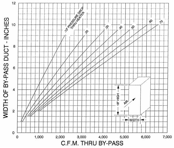
BYPASS SIZING INFORMATION
(BUILT ON THE JOB – NOT FURNISHED BY FACTORY)
On occassion when a duct furnace is incorporated in an air handling system, it may be desirable to handle a total of more CFM than the duct furnace will pass at a given static pressure drop and temperature rise. Therefore, it is necessary to arrange to bypass the additional CFM required. The size of the bypass duct can be determined by referring to the chart. This permits the static pressure drop through the bypass to balance off the drop through the heat exchanger. The bypass duct is not factory furnished and must be built on the job by the installer and a damper placed therin if required.
USE OF BYPASS CURVES
The width of the by-pass for CFM in excess of that provided through the heater may be found in the following manner:
1.Determine the CFM and pressure drop through the heater based on the heating requirement specifi cations.
2.Determine the additional CFM desired, over and above the CFM for the heating requirements.
3.Using the pressure drop which was determined from performance curves above, for the heating load, locate this pressure drop on the by-pass curves. Follow this curve until it intersects the vertical CFM line for the excess CFM desired.
4.Follow horizontal line to left to obtain width of by-pass duct.
Figure 5 - By-Pass Curve
– 7 –

INSTALLATION


 Open all disconnect switches and secure in that position before installing unit. Failure to do so may result in personal injury or death from electrical shock.
Installation must conform with local building codes, or in the absence of local codes, with the latest edition of the National Fuel Gas Code ANSI Z223.1 (NFPA 54).
A heat loss study and a complete layout of the system should be made fi rst.
When locating the unit in its permanent location, make certain that the roof is capable of carrying the additional load of the equipment. Check the net weights from the engineering data.
Make certain that clearances are provided for service, minimum clearance to combustible material and to venting cap. See below for this information. Service clearance information is given in the engineering data in Figures 1, 2 and 6. Clearances around secondary air must be unobstructed.
If the unit is installed downstream of refrigeration coils, condensate will form and collect in the bottom of the heater. Drain connections are provided to dispose of this condensate from the unit. Connect drain pipes to dispose of this condensate where necessary.


 Ducts which are outdoors must be insulated and sealed to prevent water from entering either furnace or building through duct (see section on duct and drain specifications).
Ducts connected to duct furnaces shall have removable access panels on both upstream and downstream sides of the unit. These openings shall be accessible when the unit is installed in service, and shall be of such size that smoke or refl ected light may be observed inside the casing to indicate the presence of leaks in the heating element. The covers for the openings shall be attached in such a manner as to prevent leaks.


 If a duct furnace is connected to a return air duct or any other inlet air restriction, the appliance shall be installed on the positive pressure side of the air-circulating blower.
Atmospheres containing solvents or chlorinated hydrocarbons will produce corrosive acids when coming in contact with the flames. This will greatly reduce the life of the gas duct furnace and may void the warranty. Avoid such areas.
CLEARANCES
Minimum clearances are shown in Figures 1, 2 & 6 and charts 1 & 2. It is important that clearances be maintained for servicing the unit (refer to Figures 1 & 2 for clearances necessary to pull out the burner drawer for servicing), and that minimum clearances are provided from combustible material and from the venting cap/top of unit. Clearances around the outside air hood must be unobstructed.


 Provide adequate clearance from combustibles to prevent injury or death from fire.
Figure 6 - Minimum Clearances to Combustible Material or Obstructions
|
|
|
|
|
|
|
|
|
|
|
|
Power Vent Units required 36" |
|
|
|
|
|
|
|
|
|
|
|
|
|
|
|
|
|
18" |
|
|
|
|
|
|||
|
|
|
|
(457) |
|
|
|
|
|
|
clearance above top of unit. |
|
|
|
|
|
|
|
|
|
|
|
5/16" (8) Typ. |
||
|
|
|
|
|
|
|
|
|
|
|
|
|
|
|
|
|
|
|
|
|
|
|
|
|
|
|
|
|
|
|
|
|
|
|
|
|
|
|
|
|
|
|
|
|
|
|
|
|
|
|
|
|
|
|
|
|
|
|
|
|
|
|
|
|
|
|
|
|
|
|
|
|
|
|
|
|
|
|
|
|
|
|
|
|
|
|
|
|
|
|
|
|
|
|
|
|
|
|
|
|
|
|
|
|
|
|
|
|
36" |
|
|
|
|
|
(914) |
|
|
|
|
|
36" |
|
|
|
|
|
(914) |
|
18" |
|
18" |
|
18" |
5/16" |
(457) |
|
(457) |
5/16" |
(457) |
|
|
|
Clearance |
||
(8) |
|
|
|
(8) |
|
|
|
|
For Drawer |
||
|
|
|
|
|
|
|
|
|
|
|
Pul-out |
|
|
Natural |
|
|
|
|
Ductwork |
(or Power) |
Air Flow |
|
|
|
|
Vent |
|
|
|
|
|
|
|
|
|
|
|
Furnace |
|
|
|
D3589A |
|
|
|
|
|
D3589 |
*See fi gures 1 & 2 and charts 1 & 2. |
|
|
– 8 –
VENTING
All venting installations shall be in accordance with the latest edition of “Part 7, Venting of Equipment of the National Fuel Gas Code, ANSI Z223.1 (NFPA 54), or applicable provisions of local building codes”.
Natural venting models are equipped with a vent cap designed for natural venting. Air for combustion enters at the base of the vent through a protective grille, and the design of the vent cap is such that the products of combustion are discharged at the upper section of the cap. The cap is shipped in a separate carton. It should be fastened in position as shown in Figure 7 and should not be altered in any way.


 The venting is an integral part of the unit and must not be altered in the field. If altered, excessive carbon monoxide could be produced.
Figure 7 - Vent Cap Assembly
(Natural Vented Furnaces Only)
1 |
|
2 |
|
|
4 |
|
3 |
D3591 |
|
LEFT |
FRONT |
REAR |
RIGHT |
|
|
D3591 |
|
FIELD INSTALLATION INSTRUCTIONS
1.Remove “Side Access Panel”.
2.Insert Vent Sleeve of “Vent Cap Assembly” (Item 1) thru “Top Panel Assembly” (Item 2), and over Vent Collar of “Flue Collector Assembly” (Item 3).
3.Align “Vent Cap Assembly” so it is square to “Top Panel Assembly”.
4.Fasten with “Drill Screw” or “Sheet Metal Screw” (Item 4) by reaching between “Flue Collector Assembly” (Item 3) & “Top Panel Assembly” (Item 2), and drilling through vent sleeve of “Vent Cap Assembly” into vent collar of “Flue Collector Assembly”.
5.Replace “Side Access Panel”.
NOTICE: If your unit is to be equipped with the optional extended vent cap assembly, see the special instructions supplied with the vent cap.
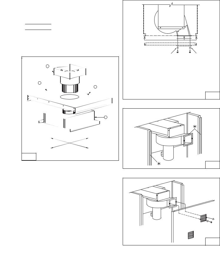
Power vented models are designed with combustion air inlet and fl ue products outlet located in the louvered side access panel. Never locate these units in an area where the flue products outlet may be directed at any fresh air vents.See Figures 8a 8b, and 8c for installation and servicing requirements.
Figure 8a - Power Venter Discharge Location
TOP VIEW
Neoprene Washers |
Screws |
*These Surfaces (indicated with an asterisk in fi gures 8a & 8b)
MUST be flush and sealed at all times to ensure the proper discharge of fl ue products from the unit.
These discharge fl anges are equipped with special gasketing, which must create an air tight seal connection around the louvers of the access panel.
Secure in place the access door to the discharge adaptor using |
||
the two screws and neoprene washers, then tighten |
|
|
the grip latches (see service access panel removal |
D3505 |
|
section). |
||
|
||
Figure 8b
D3725 |
Figure 8c
D4596 |
– 9 –
 Loading...